Embed Size (px)
Citation preview

1
STORQ System
Installation Guide

2
STORQ Installation
© 2013 Dial Global Radio Networks
All rights reserved. No parts of this work may be reproduced in any form or by any means - graphic, electronic, or mechanical, including photocopying, recording, taping, or information storage and retrieval systems - without the written permission of the publisher.
Products that are referred to in this document may be either trademarks and/or registered trademarks of the respective owners. The publisher and the author make no claim to these trademarks.
While every precaution has been taken in the preparation of this document, the publisher and the author assume no responsibility for errors or omissions, or for damages resulting from the use of information contained in this document or from the use of programs and source code that may accompany it. In no event shall the publisher and the author be liable for any loss of profit or any other commercial damage caused or alleged to have been caused directly or indirectly by this document.
Printed: April 2013
Technical Editors Kelly Kittleson
Technical Support (888)HELP-450 (435-7450)

3
Table of Contents Page Number
Part 1 System Overview 6
1.1 Equipment Inventory 6
1.2 System Diagram 7
1.3 System Integrity: Lite vs Full 8
Part 2 Installation 10
2.1 Equipment Required 10
2.2 Time Required 10
2.3 Computer Setup 11
Surge Suppression 11
2.4 STORQ Wiring 12
2.4.1 Basic Wiring Information 12
Tools Required 12
Steps Required 12
2.4.2 Control I/O Pinout 13
Contec Opto Input 13
Contec Relay Output 14
2.4.3 Audio I/O Pinout 15
Audio Output (XLR Out) 15
Audio Input (XLR In) 16

4
2.4 STORQ Wiring Cont’d….
2.4.4 Wiring for Full Systems 17
2.4.5 Wiring for Lite Systems 17
Wiring in Parallel 17
Wiring in Series 17
Return Closure 17
Silence Sensor 18
2.5 Connecting to the Internet 19
2.5.1 Router Configuration 20
2.6 Receiver Installation 20
2.6.1 Dish Alignment 20
2.6.2 Dish Peaking with the Westport Receiver 21
2.6.3 Satellite Cabling 22
2.7 Interfacing Your Traffic System 22
2.7.1 Drive Usage 22
2.8 Interfacing Your Automation System 22
Part 3 System Testing 23
3.1 Testing the System 23

5
Welcome to Dial Global Local
Thank you for choosing Dial Global Radio Networks. We look forward to providing you with our programming services. If you have questions or concerns at any point during the installation process, please contact Dial Global technical support at (888)435-7450.
Your STORQ system was shipped to you completely configured, however, it will be necessary to update and test your system once installed.
Once the system is installed, you must contact Dial Global Operations Center at (888)435-7450 before placing it on the air.

6
1 System Overview
STORQ stands for Satellite Technology Offering Real-time Quality. It differs from other satellite music delivery systems in that the music is played locally from the system's hard drives. The music is mixed with generic and localized content and imaging downloaded digitally via satellite. The end product sounds live, local, and seamless.
You control the content. If you want to pause regular programming and insert a live remote or a breaking news event, you can. Rejoining the network is as simple as clicking the start button.
STORQ is a state-of-the-art digital audio delivery system. Your commercials and other locally-produced programming can be recorded into the system and scheduled to play back during automated or live day parts. You can interface the STORQ system with many popular automation systems. STORQ has many powerful "live-assist" functions as well. For complete operational details, please see the STORQ technical operations manual.
1.1 Equipment Inventory
The STORQ system was shipped to you in two boxes. One box was shipped from our Denver facility, and the second box containing your monitor was shipped from one of our suppliers.
Included in all shipments:
STORQ computer · Westport DVB satellite receiver · Video Monitor (will arrive separately) · Mouse and Keyboard · Installation, technical, and operation manuals · Networking cables from receiver to computer
ASI 6000 Series/Contec I/O Equipment:
One - XLR Breakout Cable
One - Audio Adapter Cable
One – Relay Cable from Computer to Terminal Block (DB37)
One – Opto Cable from Computer to Terminal Block (DB37)
Two – DB37 Terminal Strips with

7
1.2 System Overview
1.3 System Integrity
The STORQ system contains sensitive software. In order to maintain system integrity, adding software or changing system configuration in any way is not supported. Changing network settings can cause the system to malfunction.
If you find that it is necessary to change configuration or add software of any type, contact Dial Global Engineering:
We are available Monday-Friday 8a.m.- 5p.m., MDT. Telephone: (720) 873-5158 E-mail: [email protected]

8
1.3 Lite vs Full Mode
The STORQ system is very flexible, and can be used in two configurations: Lite and Full.
Using the system in the Full configuration allows the STORQ system to stand alone. You can record local commercials into the system and use it for local spot playback in addition to network playback. You will need to interface your traffic system with the STORQ system.
Using the system in the Lite configuration allows you to interface the STORQ system with your existing automation system. You will need to connect some I/O in order for the interface to work correctly.
1.3.1 LITE MODE SETUP
Return Closures: (VERY IMPORTANT!) In order to enjoy the full flexibility of the STORQ system, a return closure is required from your automation system at the end of each break. There are FOUR returns needed every hour, even if the break is empty. Once a local break is triggered by the STORQ system, it sits idle and waits for a return closure from your existing automation system. Since every automation system is configured differently, you should refer to your automation system documentation for details on obtaining an end of break closure.
Wiring for Lite Systems: When using the STORQ system in conjunction with your existing automation system, you have two installation options: parallel or series. A) WIRING IN PARALLEL: When installing in parallel, wire the STORQ air output directly to your console. The control connections should be connected directly to your automation system. If you want the ability to audition cuts or record into the STORQ system, you should wire the production inputs and outputs. Since you will not be recording your local spots into the system, this step is optional. B) WIRING IN SERIES: When installing in series, wire the STORQ air output through your automation switcher, or existing automation system inputs. You may also want to wire the air output to a spare input on your console. This will make playback during a live show easier. The control connections should be connected directly to your automation system.
Wiring Control (Triggers) for Lite Mode: Wire Opto-1 (Storq Control Block) to accept a closure from other automation system. This will resume playback on Storq after the break is done.
Wire Relay-1 (Storq Control Block) to trigger local breaks on other automation system.

9
1.3.2 FULL MODE SETUP
Interfacing Your Traffic System: If you are using the STORQ system to play back your local spots (FULL configuration), you will need to interface your traffic system with the STORQ system. The STORQ system will interface with most traffic systems. Many traffic systems have built in log formats specifically designed for the STORQ system. Even if your traffic system does not directly support the STORQ system with a dedicated output, we can configure one of your traffic systems ASCII output files to work with our system in most cases.
10
2 Installation
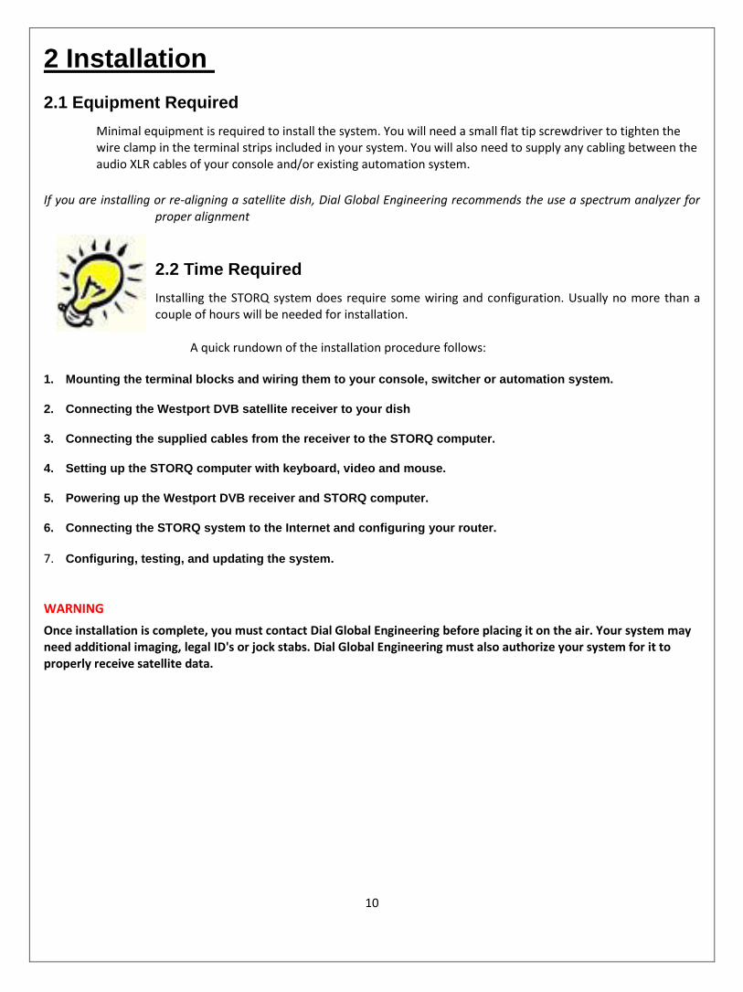
2.1 Equipment Required
Minimal equipment is required to install the system. You will need a small flat tip screwdriver to tighten the wire clamp in the terminal strips included in your system. You will also need to supply any cabling between the audio XLR cables of your console and/or existing automation system.
If you are installing or re-aligning a satellite dish, Dial Global Engineering recommends the use a spectrum analyzer for proper alignment
2.2 Time Required
Installing the STORQ system does require some wiring and configuration. Usually no more than a couple of hours will be needed for installation.
A quick rundown of the installation procedure follows:
1. Mounting the terminal blocks and wiring them to your console, switcher or automation system.
2. Connecting the Westport DVB satellite receiver to your dish
3. Connecting the supplied cables from the receiver to the STORQ computer.
4. Setting up the STORQ computer with keyboard, video and mouse.
5. Powering up the Westport DVB receiver and STORQ computer.
6. Connecting the STORQ system to the Internet and configuring your router.
7. Configuring, testing, and updating the system.
WARNING
Once installation is complete, you must contact Dial Global Engineering before placing it on the air. Your system may need additional imaging, legal ID's or jock stabs. Dial Global Engineering must also authorize your system for it to properly receive satellite data.

11
2.3 Computer Setup
Installing the computer is as simple as plugging in the monitor, mouse, and keyboard and turning it on.
WARNING
Never power the STORQ system down without properly ending your windows session: go to Start and select Shut down.
*All other connections will be labeled directly on the PC with white stickers. 2.3.1 Surge Suppression
Dial Global highly recommends an uninterruptible power supply be used with the STORQ computer. If a UPS is not available you must connect the STORQ computer to a surge suppressor device.
We recommend Tripplite ISOBar model # ISOBAR2-6 (www.tripplite.com).
Keyboard/Mouse
Monitor (VGA or DVI)

12
2.4 STORQ Wiring
2.4.1 Basic Wiring Information
We always recommend you enlist the services of a qualified engineer to install your STORQ system.
2.4.1.1 Tools Required
Screwdriver Use a slotted or Phillips screw driver depending upon the screws used to mount the terminal strips.
Drill This tool is optional. Can be used if holes are needed to mount the terminal strips.
2.4.1.2 Steps Required
Mounting the Terminal Strips The terminal strips should be mounted as near to the console as possible without exceeding the length of the cables that connect the punch blocks to the computer, typically 6 feet. Care should be taken to mount them in an indirect place that has minimal interference.
Wiring to the Console You can wire directly to the console directly or via the XLR connections. Your console either has inputs/outputs wired directly to itself, or they are wired to a punch block and the inputs/outputs are connected there. You will need to consult the console's technical manual and the station diagrams to determine where the inputs and outputs are connected.
Recommended Audio Cable We recommend Belden 8723 four-wire shielded wire. Other types of shielded wire will work as long as it can easily be screwed in the terminal strip without breaking.

13
2.4.2 Control I/O Pinout Diagrams
Opto Control Inputs (1-32)
TB1 PINS
1 2 3 4 5 6 7 8 9 10 11 12 13 14 15 16 17 18 19
Opto Common (1-16) Opto-1 Opto-2 Opto-3 Opto-4 Opto-5 Opto-6 Opto-7 Opto-8 Opto-9 Opto-10 Opto-11 Opto-12 Opto-13 Opto-14 Opto-15 Opto-16 +12v N.C.
TB2 PINS
20 21 22 23 24 25 26 27 28 29 30 31 32 33 34 35 36 37 GND
Opto Common (17-32) Opto-17 Opto-18 Opto-19 Opto-20 Opto-21 Opto-22 Opto-23 Opto-24 Opto-25 Opto-26 Opto-27 Opto-28 Opto-29 Opto-30 Opto-31 Opto-32 -12v N.C. (DO NOT USE THIS GND)
Please refer to this diagram for pin designation on the terminal strip
If you need help in determining your configuration, contact Dial Global Radio Networks Engineering:
We are available Monday-Friday 8a.m. - 5p.m., MDT.
Telephone: (720)873-5185
E-mail: [email protected]

14
Relay Control Outputs (1-16)
TB1 PINS
1 2 3 4 5 6 7 8 9 10 11 12 13 14 15 16 17 18 19
N.C. Relay-1 N.O. Relay-2 N.O. Relay-3 N.O. Relay-4 N.O. Relay-5 N.O. Relay-6 N.O. Relay-7 N.O. Relay-8 N.O. Relay-9 N.O. Relay-10 N.O. Relay-11 N.O. Relay-12 N.O. Relay-13 N.O. Relay-14 N.O. Relay-15 N.O. Relay-16 N.O. N.C. N.C.
TB2 PINS
20 21 22 23 24 25 26 27 28 29 30 31 32 33 34 35 36 37 GND
N.C. Relay-1 Common Relay-2 Common Relay-3 Common Relay-4 Common Relay-5 Common Relay-6 Common Relay-7 Common Relay-8 Common Relay-9 Common Relay-10 Common Relay-11 Common Relay-12 Common Relay-13 Common Relay-14 Common Relay-15 Common Relay-16 Common N.C. N.C.
Please refer to this diagram for pin designation on the terminal strip

15
2.4.3 Audio Science 6000 Series Onboard I/O
2.4.3.1 XLR Outputs
Line Out 1 Left
Line Out 1 Right
On-Air Output
Line Out 2 Left
Line Out 2 Right
Production Output
Line Out 3 Left
Line Out 3 Right
Not Used *
Line Out 4 Left
Line Out 4 Right
Not Used *
* Contact Dial Global Engineering if you wish to utilize Line Outputs 3 and 4 for broadcast operations.

16
2.4.3 Audio Science 6000 Series Onboard I/O
2.4.3.2 XLR Inputs
Line In 1 Left
Line In 1 Right
Mono/Stereo Source 1 **
Line In 2 Left
Line In 2 Right
Mono/Stereo Source 2 **
Line In 3 Left
Line In 3 Right
Mono/Stereo Source 3 **
Line In 4 Left
Line In 4 Right
Production/REC Input ***
** Typical use would be external audio source such as Satellite Feeds, Phone/Marti Feeds, or other
sources
*** Wire your production output from your console to this input for production recording
capabilities.

17
2.4.4 Wiring for Full Systems
When using the STORQ system to record and playback local commercials, you should wire not only the air output to your console, but also the production input and output as well. This will allow you to record audio into the STORQ, presumably from the audition bus of your console.
2.4.5 Wiring for Lite Systems
When using the STORQ system in conjunction with your existing automation system, you have two installation options: parallel or serial.
2.4.5.1 Wiring in Parallel
When installing in parallel, wire the STORQ air output directly to your console. The control connections should be connected directly to your automation system. If you want the ability to audition cuts or record into the STORQ system, you should wire the production inputs and outputs. Since you will not be recording your local spots into the system, this step is optional. For detailed wiring information, refer to section 2.4.2 Audio and Control I/O pin out.
2.4.5.2 Wiring in Series
When installing in series, wire the STORQ air output through your automation switcher, or existing automation system inputs. You may also want to wire the air output to a spare input on your console. This will make playback during a live show easier. The control connections should be connected directly to your automation system.
If you want the ability to audition audio cuts or record into the STORQ system, you may also wire the production inputs and outputs. Since you are not recording your local spots into the system, this step is optional.
2.4.5.3 Return Closure
In order to enjoy the full flexibility of the STORQ system, a return closure is required from your automation system at the end of each break even if the break is empty.
Once a local break is triggered by the STORQ system, it sits idle and waits for a return closure from your existing automation system.
Since every automation system is configured differently, you should refer to your automation system documentation for details on obtaining an end of break closure.
WARNING
Be sure that the return closure is configured even if the local break is empty.

18
2.4.5.4 Silence Sensor
In order to increase system reliability, it may be necessary to install a silence sensor in parallel with your 'Lite' STORQ system. Occasionally an existing automation system may not return a closure at the end of a local break. Depending on your automation system, this can be occur for a variety of reasons, . If your automation system requires break windowing, breaks may occasionally fall outside the prescribed window because of STORQ break loading flexibility, causing your automation system to fail to return a closure. Other possible problems could include: failure to properly schedule a required return closure and/or existing automation system instability.
A silence sensor in parallel with your station's program audio acts as a failsafe in the absence of a closure and will generate one automatically after a prescribed period of silence, usually 25 - 45 seconds.
We recommend Radio Design Lab's ACR-2. This silence sensor allows for trigger adjustment between 5 and 50 seconds.
2.5 Connecting to the Internet
In order to enjoy the full flexibility and redundancy the STORQ system has to offer, we recommend that you connect the system to a broadband internet connection. This allows the system to automatically receive any missed audio, to utilize the internet as a backup to the satellite connection, to send performance affidavits, and to send important system status information to Dial Global automatically. A broadband connection also allows technical support personnel to access your machine quickly in the event of technical problems or if you need training or assistance.
In order to maintain system integrity, a firewall has been installed and Internet browser access has been disabled on the STORQ computer. These measures help prevent the proliferation of viruses and system instability.
We recommend you use a static local IP address for the STORQ system. To enter a static IP address follow these steps:
1. Have your IP address and local gateway and DNS address ready. 2. Click on the "My Computer" icon, just to the right of the start button.
3. Click the + next to "Control Panel" and highlight "Networks Connections" 4. Right Click "LAN" and select properties

19
1. Select 'Internet Protocol (TCP/IP)" and press the "Properties" button 2. Select "Use the following IP address:" and enter your IP information. You will need to enter the IP address, subnet
mask (Usually 255.255.255.0) and Default Gateway. Enter at least one DNS server in 'Preferred DNS Server'

20
For further assistance, please contact Dial Global engineering:
We are available Monday-Friday 8a.m. - 5p.m., MDT. Telephone: (720)873-5158
2.5.1 Router Configuration
Dial Global can remotely access your STORQ computer over the Internet using Crosstec Remote ControlTM
software. Port forwarding is not necessary to do this, however, it will be required if you need remote access to the STORQ computer.
Configuring most routers is a simple process and can be completed quickly. Router and modem configuration can vary greatly. For assistance, contact your ISP's technical support department or your information technology director.
If you need further assistance, contact Dial Global Engineering: (720)873-5189
2.6 Receiver Installation
Dial Global Radio Networks broadcasts a C-Band signal on GE 8 (AMC-8), Transponder 23. This is the same satellite that most other radio services use. If you are already receiving service on this satellite, then receiver installation is simple. Just plug a RF coaxial connection into the rear of the receiver and connect the power source to it.
2.6.1 Dish Alignment
If you are installing a new dish, or realigning an existing dish, we recommend you use a spectrum analyzer for accurate alignment. AMC 8 is located at 139º W.L.
Our signal is vertically polarized. If you are using a spectrum analyzer for peaking your dish, AMC 8's vertical beacon frequency is located at 4169.00 mHz (C-band) 981.00 mHz (L-band).
2.6.2 Dish Peaking with the Westport Receiver
The Westport receiver has the capability to peak your satellite dish. In the event a spectrum analyzer is unavailable, please follow these instructions in order to properly align your Westport receiver.
The receiver must be connected to the STORQ system computer in order to configure the receiver.
WARNING If you're not using the Westport satellite receiver to power your LNB, you must use the provided in-line DC Block to prevent damage to the receiver!

21
To Peak the Satellite Dish Using the Westport Receiver:
1. Disconnect all equipment from the dish.
2. Run a cable directly from the Westport satellite receiver to the dish LNB connection. (The DC Block should not be used while peaking the dish.)
3. Turn on the receiver.
4. Press the 'Enter' button from the main display.
5. Under the Receiver Utilities menu, press the up-arrow until the display reads "Press Enter to Align Dish Now."
6. Receiver will give an audible indicator os\f signal strength and display will show current EbNo and AGC values.
7. Adjust dish until highest audible pitch is heard. Display should have greatest EbNo signal value.
8. Press 'Enter' on the Westport satellite received to turn off audible pitch or simply unplug the receiver. 2.6.3 Satellite Cabling
Proper satellite cable connections are vital for reliable system operation. We have supplied you with two cables for the satellite receiver.
The first cable, a short 1' orange section with a coupler on one end, should be plugged into the satellite port in the rear of the STORQ system.
The second cable, a 20' blue patch cable, should be connected to the end of the coupler and the satellite receiver.
If you require a longer run between the satellite receiver and STORQ system, you may use any standard CAT5 patch cable up to 200', however, the 1' orange cable and coupler must still be connected directly to the STORQ system.

22
2.7 Interfacing Your Traffic System
If you are using the STORQ system to play back your local spots (Full configuration), you will need to interface your traffic system with the STORQ system.
The STORQ system will interface with nearly all traffic systems. Many traffic systems have built in log formats specifically designed for the STORQ system. Even if your traffic system does not directly support the STORQ system with a dedicated output, we can configure one of your traffic systems ASCII output files to work with our system in most cases.
For help with traffic interfacing, please contact Dial Global Radio Networks engineering:
We are available Monday-Friday 8a.m.- 5p.m., MDT. Telephone: (720)873-5189 E-mail: [email protected]
2.7.1 Drive Usage The STORQ system comes configured with 20 audio "drives". Each audio drive contains 1000 audio cuts. Dial Global Programming utilizes many of these drives, however drives 1-8 are reserved for your use. You may record your local commercials, imaging, etc in numbers 1001-8999.
All audio on the STORQ system is backed up to an emergency backup hard drive every 2 hours. In the event of system failure the system can be configured to use this backup hard drive.
WARNING
All other drives and cut numbers are for Dial Global Network's use only. Any files recorded on these drives, risk deletion.
2.8 Interfacing Your Automation System
If you plan on interfacing the STORQ system with your existing automation system, you must connect the two systems using the control I/O block. In order for the systems to interface properly, the STORQ system needs a relay pulse at the end of all local breaks even breaks that are not filled. The STORQ system can be configured to operate in the absence of return closures, however, you will lose much of the flexibility offered by the STORQ system and breaks must be time filled.
The STORQ system will pulse relay one at the beginning of each local break. The STORQ system will then wait until it sees a return closure, on Opto 1, from your automation system before continuing playback. For added system reliability, you may consider installing a silence sensor in parallel with Opto 1 and your automation system.
We recommend wiring the STORQ system in parallel with your automation system rather than through a switcher or router. This will prevent network audio chopping prior to local breaks. Using a switcher or router is not necessary when using the STORQ system since the system remains idle for the duration of the local break.
We recommend not using satellite break windowing of any type with the STORQ system. If your system requires windowing, set the times as liberally as possible. This will allow you to take advantage of the
STORQ system's full flexibility and reliability. Remember, your automation system must always return a closure, even if the local break is empty. If no return closure is received, dead air will result!

23
3 System Testing
3.1 Testing the System
We recommend you set aside some time to familiarize yourself with the STORQ system. We are prepared to assist you and your staff with system training using remote access. Refer to the STORQ System Manual by visiting: DialGlobal.com or by viewing from the Manual CD we sent with your system.
WARNING
Once installation is complete, you must contact Dial Global Radio Networks before placing it on the air. Your system may need additional imaging, legal ID's, or jock stabs. Dial Global Radio Networks engineering must also authorize your system for it to properly receive satellite data.
For any questions or technical help… please call (888) HELP-450.