Embed Size (px)
Citation preview
MT-21E-003-D
BOC Edw ards Japan Limited Dec. 2003
Copyright 2003 BOC Edw ards Japan Limited. All rights reserved. Printed in Japan.
STP-301/451 Series Turbomolecular Pump
INSTRUCTION MANUAL (Third Edition- d)
Read through the Safety Precautions and each section of this Manual carefully before using the STP pump. Keep this Manual in a place where you can quickly access it at any time.

STP-301/451 Series Instruction Manual
1
SAFETY PRECAUTIONS The Safety Precautions in this Manual constitute guidelines to protect operators, the STP pump and its peripheral equipment. To avoid personal injury and prevent product and/or peripheral equipment damage, observe the Safety Precautions as w ell as the general safety rules (your country’s law s, regulations, safety standards and so on). If the equipment is used in a manner not specif ied by BOC Edw ards, the protection provided by the equipment may be impaired. SYMBOLS The following symbols are used in this manual:
Death or Serious Personal Injury Failure to follow the guidelines marked with this symbol may result in death or serious personal injury.
Minor Personal Injury, Product and/or Peripheral Equipment Damage Failure to follow the guidelines marked with this symbol may result in minor personal injury, product and/or peripheral equipment damage.
NOTICE
Items you must follow during operation and maintenance.
ATTENTION : refer to this manual. BOC Edw ards Japan Limited (hereafter called BOC Edw ards) cannot perfectly anticipate circumstances of all of hazards or problems. The scope of anticipation is limited to the
precautions included in the and specif ied in this
manual.

STP-301/451 Series Instruction Manual
2
◇ The STP pump is provided w ith a high-speed rotor. Secure the STP pump according to the specif ied method. Failure to do so may lead to serious personal injury, product and/or peripheral equipment damage if any abnormality/error occurs in the rotor.
◇ The STP pump operates at high temperatures w hile the baking heater is in operation. NEVER touch the STP pump and its peripheral equipment w hile the baking heater is in operation. Operators can burn hands.
◇ Execute the follow ing to prevent an accident caused by the gas. • Check the properties of the gas to be used, referring to the Material Safety Data
Sheet (MSDS) you obtain from the gas supplier. (explosive・combustible・toxic・corrosive, etc) And, keep MSDS and a safety advice of gas supplier.
• Warn of the danger of the gas w ith the w arning label w hen the use gas is hazardous chemicals materials.
• Alw ays execute gas purge in the pump w ith the inert gas, and then exhaust residual gases thoroughly from the STP pump w hen removing the STP pump from the vacuum equipment.
• Secure safety by w earing personal protective equipment w hen using the gas w hich might inf luence damage health. In addition, take appropriate measure for depending upon the properties of the gas to be used.
◇ Exhaust residual gas thoroughly w hen disposing of the STP pump. If the STP pump is used for any toxic or reactive gas, alw ays clean the STP pump and dispose of it as industrial w aste in accordance w ith guidelines given by the national and/or local government. Residual gas in the STP pump may cause an accident w hich, for certain gases, may involve serious injury or death.
STP-301/451 Series Instruction Manual
3
◇ NEVER use any gas that is not specif ied as usable in this Manual. The use of such gas may corrode the STP pump and damage it.
◇ A hazardous live voltage may exist at connector/terminal that marked . DO NOT touch the terminal. Doing so may result in electric shock. When operating connection/disconnection to terminal, alw ays pow er OFF the STP pump (Sw itch the breaker "OFF").
◇ Alw ays check the STP pump has stopped, then turn OFF the primary pow er (sw itch the breaker “OFF”) before proceeding to any of the follow ing operations. Failure to do so may cause the STP pump to rotate accidentally, w hich may injure operators seriously or result in electric shock. Moreover, do not remove the connecter w hile the pump is rotating. The voltage might be output to connector according to the rotational speed, and it causes the electric shock or the failure. • Connect or disconnect cables; • Perform maintenance and inspections such as replacement of fuses as w ell as
inspections of deposit and/or the air cooling fan; or • Perform investigations into probable causes and action/measures taken in the event
of occurrence of a problem. ◇ DO NOT perform the insulation test (insulation resistance test and w ithstand voltage test)
to the STP control unit and STP pump. When performing the insulation test to your equipment, turn "OFF" the STP control unit. The varistor for the pow er supply line protection is installed to the STP control unit. DO NOT perform the insulation test w ith the varistor installed. Doing so may result in product damage.
◇ When removing or installing the pump or at maintenance and inspection, follow the precautions below . Failure to do so might hurt your back or cause injuries due to occurrence of an accident such as fall. • Use a crane or the like w hen lif ting the heavy product of 18kg or more. • When lif ting by hands for unavoidable reason, tw o or more people must alw ays
conduct it. • When lif ting STP control unit w ith handles, support bottom of STP control unit, do not
have only handle. ◇ When "emergency off" (EMO) circuit is installed in the vacuum equipment, consider the
follow ing to stop the STP pump safely w hen the EMO circuit operates. • When the EMO circuit operates, atmosphere might be introduced in the STP pump
depending upon the backing pump. Unite the exhaust gas system to prevent atmosphere from being introduced into the STP pump w hen the EMO circuit operates. (example: shut the valve) When atmosphere is introduced into the STP pump, the touch dow n bearing may not operate normally.
◇ Install the STP control unit not only by f itting it w ith the front panel f itting screw s but also by supporting it from the bottom side. Fitting the STP control unit w ith the screw s only cannot sustain its w eight, and therefore resulting in product damage.
◇ Alw ays use the STP pump and STP control unit w ith same model name, w hich are specif ied on their ow n nameplate. If use the units having different model names, they may not be used. In the latter case, contact service off ice. If you use the units having the same model name but different serial numbers or change the length of the STP connection cable, the tuning is required. They may not function normally w hen they are used w ithout

STP-301/451 Series Instruction Manual
4
tuning. Once tuning is completed, re-tuning is not required unless the configuration (the STP pump serial number, the STP control unit serial number, and the STP connection cable length) is changed.
STP-301/451 Series Instruction Manual
5
STP-301/451 Series
◇ Use the STP connection cable that has a label aff ixed The use of different cables may result in product damage.
◇ Connect the cables securely. NEVER bend nor place heavy objects on the cable. Doing so may result in electric shock or product damage.
◇ NEVER remove the splinter shield from the STP pump. Doing so may result in product damage.
◇ DO NOT put foreign objects into the STP pump. Doing so may result in product damage. ◇ Alw ays use the pow er voltage specif ied on the nameplate for the primary pow er voltage
of the STP control unit. Wire the pow er cable securely. Incorrect w iring may result in electric shock or product damage.
◇ The w ipes used for clean the f lange of the pump might become hazardous w aste depending upon the solvent (alcohol). Dispose of the contaminated w ipes appropriately according to the regulations of each national and/or local government.
◇ NEVER turn OFF the primary pow er (DO NOT sw itch the breaker “OFF”) w hile the STP pump is rotating. Doing so may result in product damage.
◇ Perform investigations into probable causes and remove them before restarting the STP pump in the event of the occurrence of a problem. The use of the abnormal STP pump may result in product damage.
◇ DO NOT move the STP pump and the STP control unit w hile the STP pump is in operation. Doing so may result in product damage.

STP-301/451 Series Instruction Manual
6
INTRODUCTION Thank you very much for purchasing BOC Edwards’ turbomolecular pump. The turbomolecular pump is designed to be installed in the vacuum equipment to exhaust gases from it. This manual covers all items necessary to ensure safe installation, operation and maintenance of the following series of the STP-301/STP-451 turbomolecular pump:
Model Name Specification
• STP-301 High-vacuum type • STP-451 High-vacuum type • STP-301C High-vacuum type, chemical specific *1 • STP-451C High-vacuum type, chemical specific *1
For the specifications of other models, contact BOC Edwards. In this manual, the above STP pump series is collectively called the "STP pump."
APPLIED STANDARDS The STP pump conforms to the following directives and standards: ◇ Applied Directives
• EC Machinery Directive • EC Electromagnetic Compatibility Directive • EC Low Voltage Directive
◇ Applied Standards
• EN292-1 • EN292-2 • EN60204-1 • EN61326 (class A) • EN61000-6-2
◇ Applied Standards (Only a some model)*2
• UL3101-1, 1993 (Electrical Equipment for Laboratory Use; Part 1 : General Requirements)
*1: Chemical specific: STP pump with anti-corrosive treatment (responding to chlorine, fluorine or other system gases) *2: Contact BOC Edwards about recognized model
STP-301/451 Series Instruction Manual
7
PRECAUTIONS 1) No part of this manual may be reproduced in any form by any means without prior
written permission from BOC Edwards. 2) BOC Edwards pursues a policy of continuing improvement in design and
performance of this product. The right is, therefore, reserved to vary specifications and design without notice. Understand that the product you purchased and its contents including specifications described in this manual may differ.
REQUEST If you find inaccuracies or errors in this manual, advise distributor or the nearest Service office.
STP-301/451 Series Instruction Manual
8
LIMITED WARRANTY This WARRANTY applies to the customer to whom BOC Edwards has delivered this product.
1. WARRANTY PERIOD: BOC Edwards warrants this product against defects for a period of two (2) years from the date of delivery or during the period specified in the agreement made by and between the customer and BOC Edwards.
2. ITEM WARRANTED: 1) This warranty applies only to the product delivered from BOC Edwards to the
customer. 2) If any defect is found during this period, BOC Edwards will, at its option, repair
or recondition the product free of charge. The costs for repair or replacement of the product after the warranty period has passed will be at the customer's own charge.
3. DISCLAIMER: BOC Edw ards makes no w arranty w ith respect to any damage occurred due to any of the follow ing during the w arranty period: 1) Handling, operation or maintenance other than that specif ied herein; 2) Failure to follow any of the w arnings or cautions enumerated under
or ;
3) Installation, operation or maintenance using parts w hich are not specif ied by BOC Edw ards;
4) Maintenance personnel other than those authorized by BOC Edw ards or service off ice have disassembled, reconditioned, or tampered the product;
5) Defect resulting from the not-specif ied use of the product. 6) When the product is used under special conditions w ithout obtaining the w ritten
consent of BOC Edw ards (Particular gases, strong magnetic f ield and the radiation are added to the product.);
7) Defect resulting from deposit; 8) Water cooling system defect resulting from w ater quality used; 9) Defect resulting from the installation of the product (Exclude the installation by
authorized personnel.) 10) Deterioration in the external because of use (Discoloration, scratches and so forth) 11) Product damage occurred during transport or other factors not attributable to BOC
Edw ards; 12) Product breakage or damage due to natural disasters, f ire or other external factors; 13) Deterioration in the basic performance due to the use of the product beyond limits of
the use; 14) Any direct, incidental or consequential damage resulting from the use of the product; 15) When continuously operated w ithout overhaul after the WARNING indication
(“WARNING” message) on the LCD display; 16) Overhaul and replacement of maintenance parts;

STP-301/451 Series Instruction Manual
9
4. SPARE PARTS: Fuse and air cooling fan for control unit Touch down bearing Heater
STP-301/451 Series Instruction Manual
8
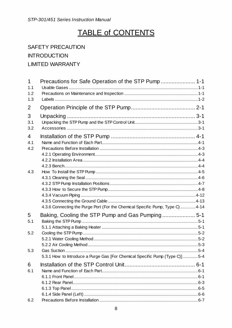
TABLE of CONTENTS
SAFETY PRECAUTION INTRODUCTION LIMITED WARRANTY 1 Precautions for Safe Operation of the STP Pump ...................... 1-1 1.1 Usable Gases ..............................................................................................................1-1 1.2 Precautions on Maintenance and Inspection ...............................................................1-1 1.3 Labels ..........................................................................................................................1-2
2 Operation Principle of the STP Pump......................................... 2-1 3 Unpacking .................................................................................. 3-1 3.1 Unpacking the STP Pump and the STP Control Unit......................................................3-1 3.2 Accessories ................................................................................................................3-1
4 Installation of the STP Pump ...................................................... 4-1 4.1 Name and Function of Each Part..................................................................................4-1 4.2 Precautions Before Installation ....................................................................................4-3
4.2.1 Operating Environment........................................................................................4-3 4.2.2 Installation Area ..................................................................................................4-4 4.2.3 Bench..................................................................................................................4-4
4.3 How To Install the STP Pump .......................................................................................4-5 4.3.1 Cleaning the Seal ................................................................................................4-6 4.3.2 STP Pump Installation Positions ...........................................................................4-7 4.3.3 How to Secure the STP Pump.............................................................................4-8 4.3.4 Vacuum Piping ..................................................................................................4-12 4.3.5 Connecting the Ground Cable...........................................................................4-13 4.3.6 Connecting the Purge Port (For the Chemical Specif ic Pump, Type C) .............4-14
5 Baking, Cooling the STP Pump and Gas Pumping ..................... 5-1 5.1 Baking the STP Pump ...................................................................................................5-1
5.1.1 Attaching a Baking Heater ..................................................................................5-1 5.2 Cooling the STP Pump ..................................................................................................5-2
5.2.1 Water Cooling Method.........................................................................................5-2 5.2.2 Air Cooling Method..............................................................................................5-3
5.3 Gas Suction .................................................................................................................5-4 5.3.1 How to Introduce a Purge Gas [For Chemical Specif ic Pump (Type C)].............5-4
6 Installation of the STP Control Unit............................................. 6-1 6.1 Name and Function of Each Part..................................................................................6-1
6.1.1 Front Panel..........................................................................................................6-1 6.1.2 Rear Panel...........................................................................................................6-3 6.1.3 Top Panel ............................................................................................................6-5 6.1.4 Side Panel (Left) .................................................................................................6-6
6.2 Precautions Before Installation ....................................................................................6-7
STP-301/451 Series Instruction Manual
9
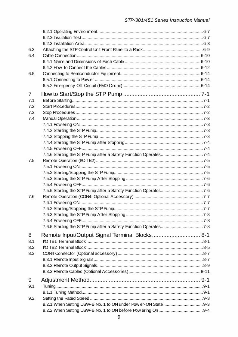
6.2.1 Operating Environment........................................................................................6-7 6.2.2 Insulation Test.....................................................................................................6-7 6.2.3 Installation Area ..................................................................................................6-8
6.3 Attaching the STP Control Unit Front Panel to a Rack..................................................6-9 6.4 Cable Connection.......................................................................................................6-10
6.4.1 Name and Dimensions of Each Cable ...............................................................6-10 6.4.2 How to Connect the Cables ..............................................................................6-12
6.5 Connecting to Semiconductor Equipment...................................................................6-14 6.5.1 Connecting to Pow er ........................................................................................6-14 6.5.2 Emergency Off Circuit (EMO Circuit).................................................................6-14
7 How to Start/Stop the STP Pump ................................................ 7-1 7.1 Before Starting.............................................................................................................7-1 7.2 Start Procedures..........................................................................................................7-2 7.3 Stop Procedures ..........................................................................................................7-2 7.4 Manual Operation.........................................................................................................7-3
7.4.1 Pow ering ON.......................................................................................................7-3 7.4.2 Starting the STP Pump.........................................................................................7-3 7.4.3 Stopping the STP Pump.......................................................................................7-3 7.4.4 Starting the STP Pump after Stopping.................................................................7-4 7.4.5 Pow ering OFF.....................................................................................................7-4 7.4.6 Starting the STP Pump after a Safety Function Operates...................................7-4
7.5 Remote Operation (I/O TB2) .........................................................................................7-5 7.5.1 Pow ering ON.......................................................................................................7-5 7.5.2 Starting/Stopping the STP Pump..........................................................................7-5 7.5.3 Starting the STP Pump After Stopping ................................................................7-6 7.5.4 Pow ering OFF.....................................................................................................7-6 7.5.5 Starting the STP Pump after a Safety Function Operates...................................7-6
7.6 Remote Operation (CON4: Optional Accessory) .........................................................7-7 7.6.1 Pow ering ON.......................................................................................................7-7 7.6.2 Starting/Stopping the STP Pump..........................................................................7-7 7.6.3 Starting the STP Pump After Stopping ................................................................7-8 7.6.4 Pow ering OFF.....................................................................................................7-8 7.6.5 Starting the STP Pump after a Safety Function Operates...................................7-8
8 Remote Input/Output Signal Terminal Blocks.............................. 8-1 8.1 I/O TB1 Terminal Block .................................................................................................8-1 8.2 I/O TB2 Terminal Block .................................................................................................8-5 8.3 CON4 Connector (Optional accessory) .......................................................................8-7
8.3.1 Remote Input Signals...........................................................................................8-7 8.3.2 Remote Output Signals........................................................................................8-9 8.3.3 Remote Cables (Optional Accessories)............................................................8-11
9 Adjustment Method..................................................................... 9-1 9.1 Tuning ..........................................................................................................................9-1
9.1.1 Tuning Method.....................................................................................................9-1 9.2 Setting the Rated Speed ..............................................................................................9-3
9.2.1 When Setting DSW-B No. 1 to ON under Pow er-ON State.................................9-3 9.2.2 When Setting DSW-B No. 1 to ON before Pow ering On.....................................9-4

STP-301/451 Series Instruction Manual
10
10 Safety Functions ...................................................................... 10-1 10.1 Pow er Failure.............................................................................................................10-1 10.2 Abnormal State of Magnetic Bearing .........................................................................10-3 10.3 Excessive Vibration...................................................................................................10-3 10.4 Motor Driver Overload................................................................................................10-3 10.5 Overheating Inside the STP Pump..............................................................................10-3 10.6 Overheating Inside the STP Control Unit ....................................................................10-3 10.7 Overspeed.................................................................................................................10-3
11 Troubleshooting, Maintenance and Inspection ..........................11-1 11.1 Troubleshooting Immediately After An Abnormality/Error Occurs .............................11-1
11.1.1 In Case of a Pow er Failure: .........................................................................11-1 11.1.2 In Other Cases .............................................................................................11-1
11.2 When Error Message is Displayed.............................................................................11-2 11.2.1 Error Messages ...........................................................................................11-2 11.2.2 Displaying Past Abnormalities/Errors and Accumulated Running-Time .......11-5 11.2.3 Abnormalities When Pow ering ON...............................................................11-7 11.2.4 Abnormalities When Performing the STP Pump Start Operation ..................11-7 11.2.5 Other Abnormalities .....................................................................................11-8
11.3 Maintenance and Inspection ......................................................................................11-9 11.3.1 Inspecting the Air Cooling Fan .....................................................................11-9 11.3.2 Replacing the Fuses ..................................................................................11-10 11.3.3 Cleaning and Decontamination...................................................................11-11 11.3.4 Inspecting for Deposit................................................................................11-11 11.3.5 Overhaul ....................................................................................................11-12 11.3.6 Transporting for Repair or Overhaul..........................................................11-13
12 Storage and Disposal ............................................................... 12-1 12.1 Storage of the STP Pump...........................................................................................12-1 12.2 Storage of the STP Control Unit .................................................................................12-1 12.3 Disposal .....................................................................................................................12-2
13 Specifications and Accessories................................................. 13-1 13.1 Specif ications of the STP Pump.................................................................................13-1 13.2 Specif ications of the STP Control Unit .......................................................................13-6
UNIT CONVERSION TABLE
ANNEX
MALFUNCTION INFORMATION STP Series / Global Service Network
STP-301/451 Series Instruction Manual
11
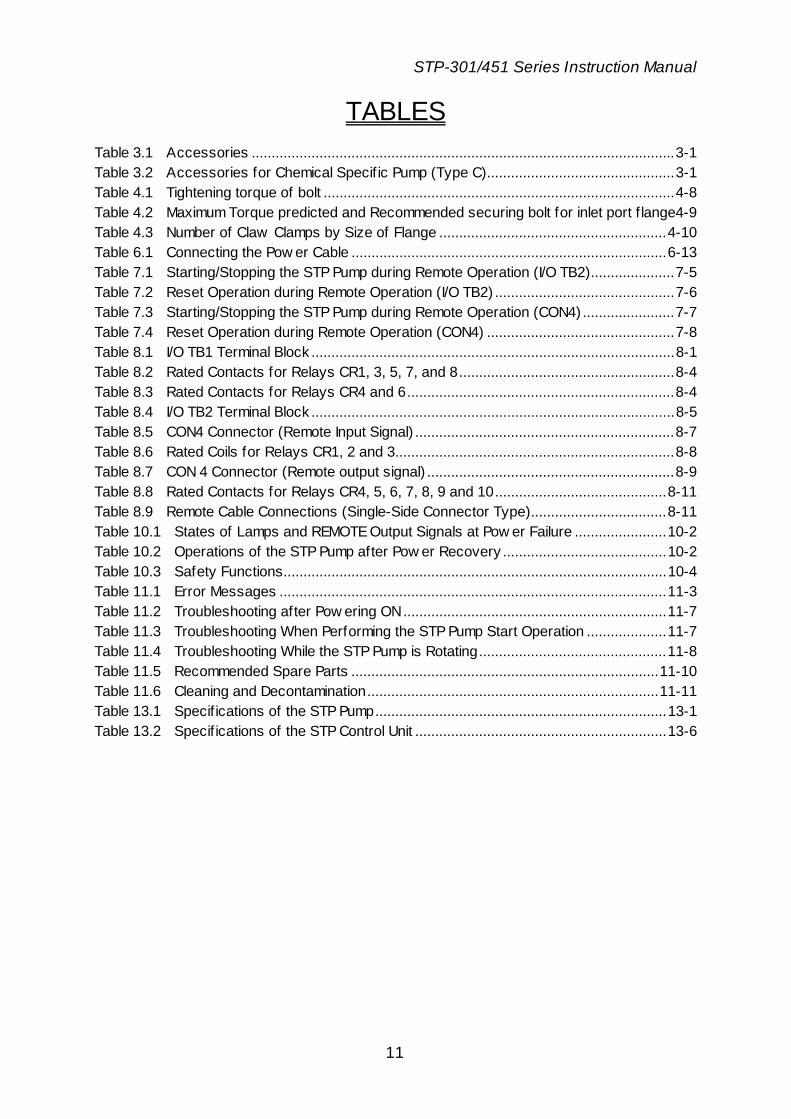
TABLES Table 3.1 Accessories ..........................................................................................................3-1 Table 3.2 Accessories for Chemical Specif ic Pump (Type C)...............................................3-1 Table 4.1 Tightening torque of bolt ........................................................................................4-8 Table 4.2 Maximum Torque predicted and Recommended securing bolt for inlet port f lange4-9 Table 4.3 Number of Claw Clamps by Size of Flange .........................................................4-10 Table 6.1 Connecting the Pow er Cable ...............................................................................6-13 Table 7.1 Starting/Stopping the STP Pump during Remote Operation (I/O TB2).....................7-5 Table 7.2 Reset Operation during Remote Operation (I/O TB2) .............................................7-6 Table 7.3 Starting/Stopping the STP Pump during Remote Operation (CON4) .......................7-7 Table 7.4 Reset Operation during Remote Operation (CON4) ...............................................7-8 Table 8.1 I/O TB1 Terminal Block ...........................................................................................8-1 Table 8.2 Rated Contacts for Relays CR1, 3, 5, 7, and 8......................................................8-4 Table 8.3 Rated Contacts for Relays CR4 and 6...................................................................8-4 Table 8.4 I/O TB2 Terminal Block ...........................................................................................8-5 Table 8.5 CON4 Connector (Remote Input Signal) .................................................................8-7 Table 8.6 Rated Coils for Relays CR1, 2 and 3......................................................................8-8 Table 8.7 CON 4 Connector (Remote output signal) ..............................................................8-9 Table 8.8 Rated Contacts for Relays CR4, 5, 6, 7, 8, 9 and 10...........................................8-11 Table 8.9 Remote Cable Connections (Single-Side Connector Type)..................................8-11 Table 10.1 States of Lamps and REMOTE Output Signals at Pow er Failure .......................10-2 Table 10.2 Operations of the STP Pump after Pow er Recovery .........................................10-2 Table 10.3 Safety Functions................................................................................................10-4 Table 11.1 Error Messages .................................................................................................11-3 Table 11.2 Troubleshooting after Pow ering ON..................................................................11-7 Table 11.3 Troubleshooting When Performing the STP Pump Start Operation ....................11-7 Table 11.4 Troubleshooting While the STP Pump is Rotating...............................................11-8 Table 11.5 Recommended Spare Parts .............................................................................11-10 Table 11.6 Cleaning and Decontamination.........................................................................11-11 Table 13.1 Specif ications of the STP Pump.........................................................................13-1 Table 13.2 Specif ications of the STP Control Unit ...............................................................13-6
STP-301/451 Series Instruction Manual
12
FIGURES Figure 2.1 Cross Sectional View of the STP Pump ...............................................................2-2 Figure 4.1 Configuration of the STP Pump.............................................................................4-2 Figure 4.2 Installation of the STP Pump to the Vacuum Equipment........................................4-5 Figure 4.3 STP Pump Installation Positions.............................................................................4-7 Figure 4.4 Positions of the Outlet Port on the Horizontally or Slanted Installed STP Pump ....4-7 Figure 4.5 Example of securing the STP pump
(When securing the inlet port w ith bolts) ....................................................4-9 Figure 4.6 Example of securing the STP pump
(When securing the inlet port f lange w ith claw clamps)...........................4-10 Figure 4.7 Example of securing the STP pump
(When installing the damper in the inlet port f lange)..................................4-11 Figure 4.8 Connecting the Purge Port..................................................................................4-14 Figure 5.1 Attaching Positions of the Cooling Unit and Baking Heater...................................5-5 Figure 6.1 STP Control Unit Front Panel.................................................................................6-2 Figure 6.2 STP Control Unit Rear Panel..................................................................................6-4 Figure 6.3 STP Control Unit Top Panel ...................................................................................6-5 Figure 6.4 STP Control Unit Side Panel (Left) ........................................................................6-6 Figure 6.5 Peripheral Spaces of the STP Control Unit ...........................................................6-8 Figure 6.6 Example of Securing the STP Control Unit............................................................6-9 Figure 6.7 External Dimensions of Ground Cable................................................................6-10 Figure 6.8 External Dimensions of STP Connection Cable...................................................6-10 Figure 6.9 External Dimensions of STP Connection Cable...................................................6-11 Figure 6.10 How to Secure the Pow er Cable......................................................................6-13 Figure 7.1 STP Pump Operation Procedures .........................................................................7-9 Figure 8.1 I/O TB1 Remote Output Signal Terminal Block.......................................................8-3 Figure 8.2 I/O TB2 Remote Input Signal Terminal Block..........................................................8-6 Figure 8.3 CON4 Remote Input Signal Connector ..................................................................8-8 Figure 8.4 CON4 Remote Output Signal Connector .............................................................8-10 Figure 9.1 Tuning Procedures ...............................................................................................9-2 Figure 9.2 LCD Message in Rated Speed Setting Mode ........................................................9-5 Figure 13.1 External Appearance of the STP Pump [w ithout Anti-Corrosion Treatment]
(Example: STP-301) ...................................................................................13-2 Figure 13.2 External Appearance of the STP Pump [Chemical Specif ic Type C]
(Example: STP-301C).................................................................................13-3 Figure 13.3 Label Aff ixing Position for the STP Pump .........................................................13-4 Figure 13.4 Label Aff ixing Positions for the Optional Accessories.....................................13-5 Figure 13.5 External Appearance of the the STP Control Unit.............................................13-8 Figure 13.6 Label Aff ixing Positions for the STP Control Unit..............................................13-9

STP-301/451 Series Instruction Manual
1-1
Inst
alla
tion
1 Precautions for Safe Operation of the STP Pump 1.1 Usable Gases
Chlorine or fluorine system gases can be used in chemical specific pumps (STP-301C/STP-451C or other models). When you use gases including alkaline metals, but excluding Li, gases including Ga, Hg, In, or Sn, or HBr, contact BOC Edwards.
◇ To prevent an accident, confirm the characteristics of gases to be used,
referring to the Material Safety Data Sheet (MSDS) you obtain from the gas supplier. And, keep MSDS and a safety advice of gas supplier.
◇ NEVER use corrosive gases (chlorine, f luorine, or other system gases) in the
STP-301/STP-451 pump or other models w ithout anti-corrosion treatment. ◇ Introduce a dry N2 gas (purge gas) to protect the inside of the STP pump w hen
using reactive or corrosive gases. ◇ Cool the STP pump to prevent the STP pump from overheating w hen pumping
gases. 1.2 Precautions on Maintenance and Inspection
Read through Section 11, "Troubleshooting, Maintenance and Inspection" before performing any maintenance or inspection of the STP pump or the STP control unit (such as fuse replacement).
◇ Alw ays turn OFF the primary pow er (sw itch the breaker "OFF") before
performing any maintenance. ◇ NEVER touch any portions other than those designated w hen performing
maintenance. Careless touch may cause electric shock and/or a short-circuiting of the internal circuit, resulting in product damage or a problem.
STP-301/451 Series Instruction Manual
1-2
Installation
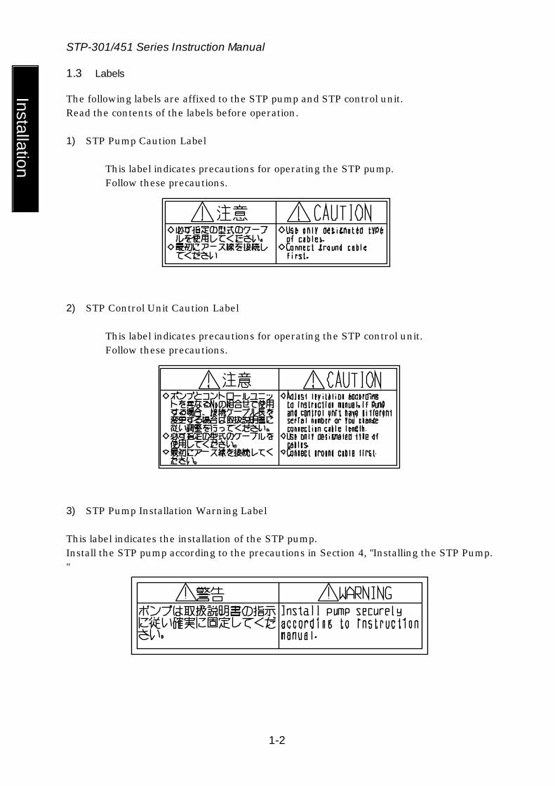
1.3 Labels
The following labels are affixed to the STP pump and STP control unit. Read the contents of the labels before operation. 1) STP Pump Caution Label
This label indicates precautions for operating the STP pump. Follow these precautions.
2) STP Control Unit Caution Label
This label indicates precautions for operating the STP control unit. Follow these precautions.
3) STP Pump Installation Warning Label This label indicates the installation of the STP pump. Install the STP pump according to the precautions in Section 4, "Installing the STP Pump. "

STP-301/451 Series Instruction Manual
1-3
Inst
alla
tion
4) Connector Caution Label
i. This label indicates the lock of the connector ii. This label instructs operators to prevent the connectors from being
disconnected while the STP pump is in operation.
5) STP Control Unit Safety Instruction Label
This label indicates instructions before operating the STP control unit.
6) High Voltage Device Caution Label
The STP control unit is equipped with a high voltage device. This label warns operators to pay attention to the high voltage device.
7) Rotational Direction Instruction Label
This label indicates the rotational direction of the STP pump. The STP pump rotates in this direction.
STP-301/451 Series Instruction Manual
1-4
Installation
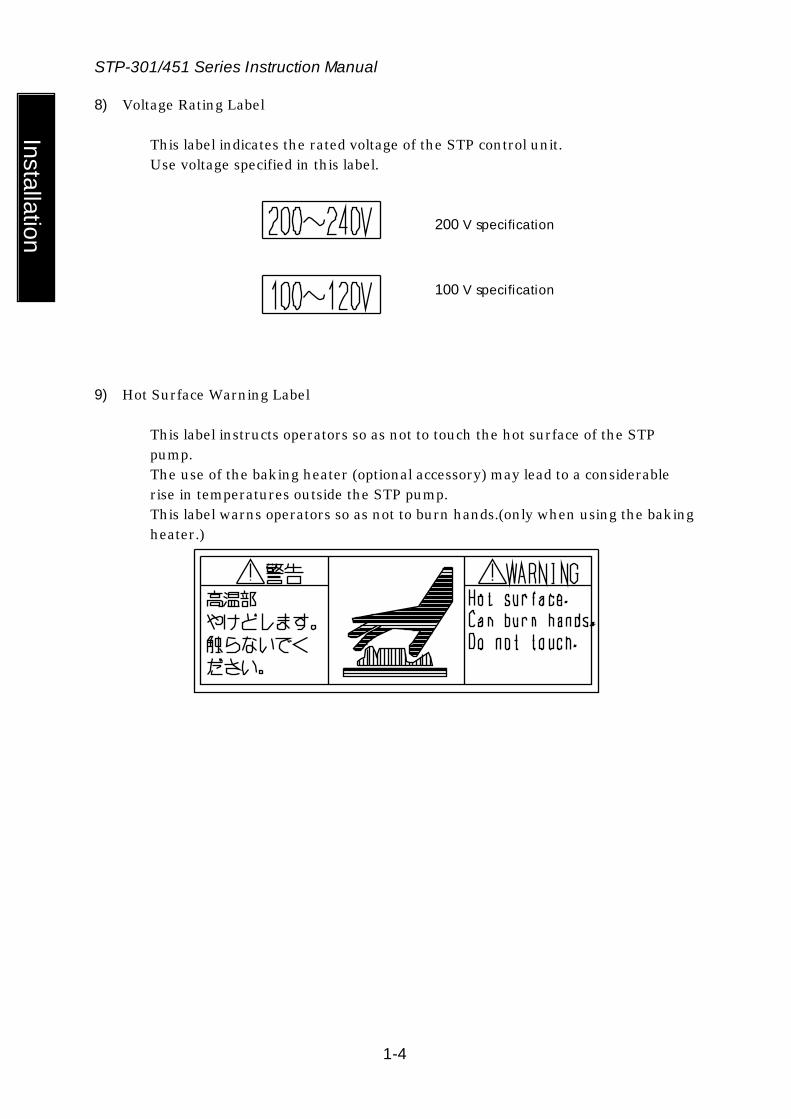
8) Voltage Rating Label
This label indicates the rated voltage of the STP control unit. Use voltage specified in this label.
200 V specification
100 V specification
9) Hot Surface Warning Label
This label instructs operators so as not to touch the hot surface of the STP pump. The use of the baking heater (optional accessory) may lead to a considerable rise in temperatures outside the STP pump. This label warns operators so as not to burn hands.(only when using the baking heater.)

STP-301/451 Series Instruction Manual
2-1
Inst
alla
tion
2 Operation Principle of the STP Pump The STP-301/451 is a series of magnetically-levitated turbomolecular pumps, featuring the following:
• Oil free • Low vibration • High reliability
The STP pump is configured so that rotor blade (1) and stator blade (2) are aligned alternately in the axial direction. Gas molecules are pumped from the inlet port to the outlet port by the high speed rotation of the rotor. Rotor blade (1) is supported by the magnetic bearing without mechanical contact. Therefore the STP pump requires no lubrication oil unlike conventional turbomolecular pumps using ball bearings. The magnetic bearing consists of 3 pairs of active magnetic bearings. The rotor is supported in the radial direction by 2 pairs of radial direction active magnetic bearings that consist of radial sensor (3) and radial electromagnet (4). A pair of axial direction active magnetic bearings consists of axial sensor (5) and axial electromagnet (6) to support the rotor in the axial direction. Because the rotor is thus supported without mechanical contact, it can rotate with low vibration. There is less heat generated from magnetic bearings because there is no friction. Therefore the STP pump requires no cooling. However, the STP pump requires water cooling or air cooling during baking and gas pumping. Taking into consideration a breakage of magnetic bearings, touch down bearings (7) and (8) coated with solid lubrication have been installed. They do not contact the rotor during the rated operation. A radial sensor, an axial sensor, a rotational speed sensor and a temperature sensor always monitor the magnetic bearing as well as the rotor. If an abnormality/error occurs, the rotor will stop.

STP-301/451 Series Instruction Manual
2-2
Installation
(1) Rotor Blade
(2) Stator Blade
(3) Radial Sensor
(4) Radial Electromagnet
(6) Axial Electromagnet
(5) Axial Sensor
(8) Touch Down Bearing
(7) Touch Down Bearing
Figure 2.1 Cross Sectional View of the STP Pump
STP-301/451 Series Instruction Manual
3-1
Inst
alla
tion
3 Unpacking 3.1 Unpacking the STP Pump and the STP Control Unit
Check the following before unpacking the STP pump and STP control unit. 1) Check the package for bruises, breakage, wetness, and other.
If there is any abnormality/error or it is judged necessary to return the product, contact BOC Edwards or the selling agency.
2) Check the contents of the package. See Section 3.2, "Accessories."
◇ Be careful not to scratch the f lange of the STP pump.
Before installing the STP pump, check w hether or not there are scratches on the surface.
◇ It is recommended to keep the packaging materials, such as the corrugated f iberboard container and cushioning material for possible reuse.
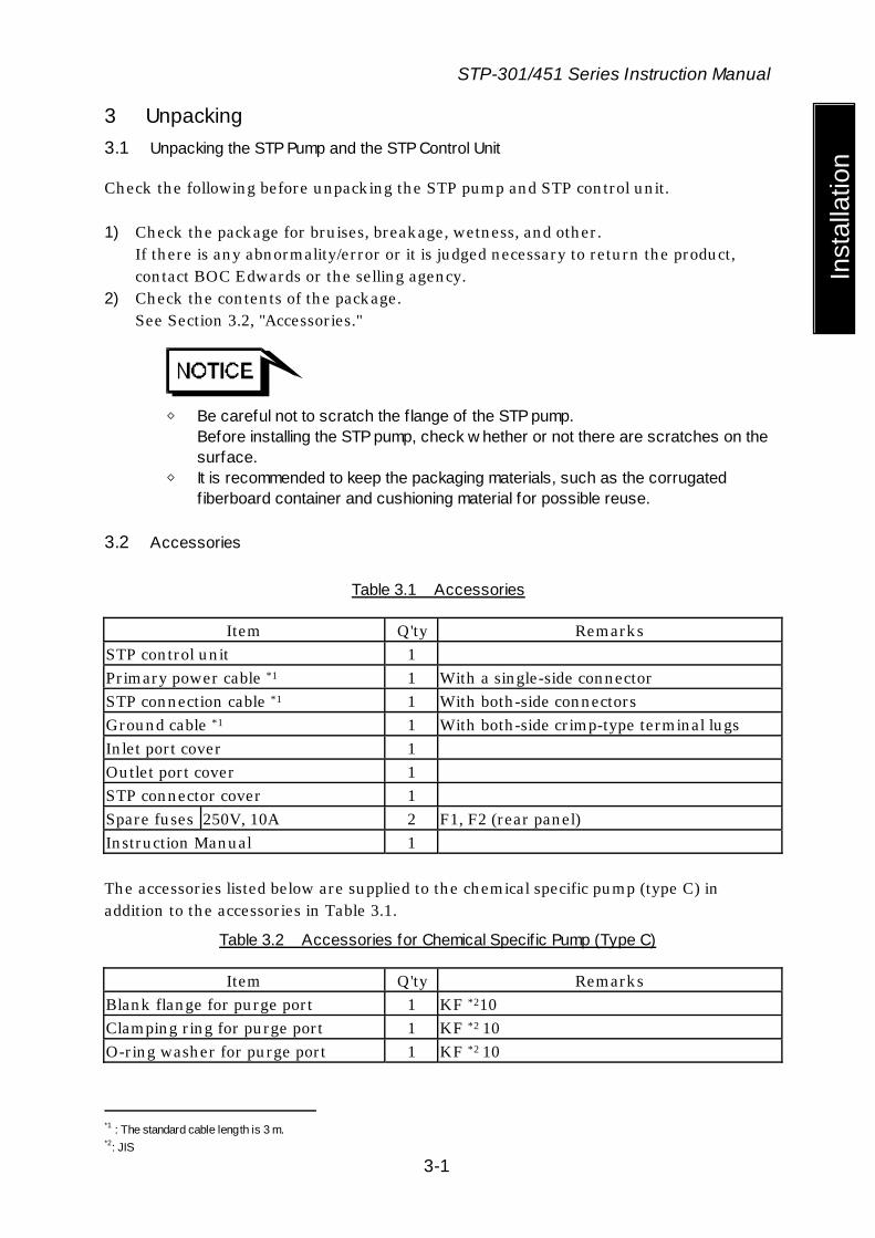
3.2 Accessories
Table 3.1 Accessories
Item Q'ty Remarks STP control unit 1 Primary power cable *1 1 With a single-side connector STP connection cable *1 1 With both-side connectors Ground cable *1 1 With both-side crimp-type terminal lugs Inlet port cover 1 Outlet port cover 1 STP connector cover 1 Spare fuses 250V, 10A 2 F1, F2 (rear panel) Instruction Manual 1 The accessories listed below are supplied to the chemical specific pump (type C) in addition to the accessories in Table 3.1.
Table 3.2 Accessories for Chemical Specif ic Pump (Type C)
Item Q'ty Remarks Blank flange for purge port 1 KF *210 Clamping ring for purge port 1 KF *2 10 O-ring washer for purge port 1 KF *2 10
*1 : The standard cable length is 3 m. *2: JIS

STP-301/451 Series Instruction Manual
4-1
Inst
alla
tion
4 Installation of the STP Pump 4.1 Name and Function of Each Part
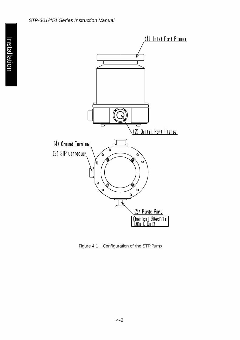
(1) Inlet Port Flange (ICF*1, VG*1, ISO, and other) Connected to the vacuum equipment (at the high vacuum side).
(2) Outlet Port Flange (KF*2 25)
Connected to the inlet port side of the backing pump. (3) STP Connector (41 pins)
Connected to the STP connection cable.
(4) Ground Terminal Used for grounding.
Connect the ground cable between this terminal and the ground terminal of the STP control unit.
The ground terminal is marked with label.
(5) Purge Port (KF*2 10)[Chemical Specific Pump (Type C)] Introduces a purge gas.
This port is attached only to the chemical specific pump (type C). In order to protect the inside of the STP pump when pumping reactive or corrosive gases. The STP pump is delivered with a blank flange attached to this port.
*1 : JVIA Standard *2: JIS
STP-301/451 Series Instruction Manual
4-2
Installation
Figure 4.1 Configuration of the STP Pump
STP-301/451 Series Instruction Manual
4-3
Inst
alla
tion
4.2 Precautions Before Installation
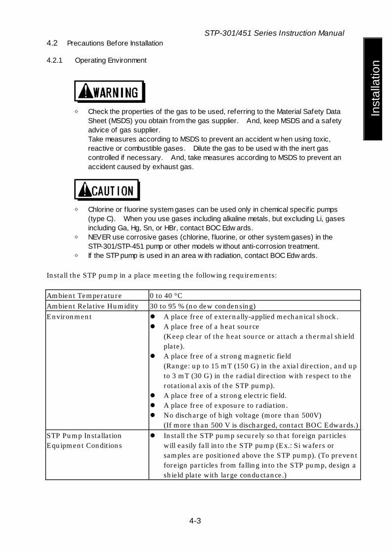
4.2.1 Operating Environment
◇ Check the properties of the gas to be used, referring to the Material Safety Data
Sheet (MSDS) you obtain from the gas supplier. And, keep MSDS and a safety advice of gas supplier. Take measures according to MSDS to prevent an accident w hen using toxic, reactive or combustible gases. Dilute the gas to be used w ith the inert gas controlled if necessary. And, take measures according to MSDS to prevent an accident caused by exhaust gas.
◇ Chlorine or f luorine system gases can be used only in chemical specif ic pumps
(type C). When you use gases including alkaline metals, but excluding Li, gases including Ga, Hg, Sn, or HBr, contact BOC Edw ards.
◇ NEVER use corrosive gases (chlorine, f luorine, or other system gases) in the STP-301/STP-451 pump or other models w ithout anti-corrosion treatment.
◇ If the STP pump is used in an area w ith radiation, contact BOC Edw ards. Install the STP pump in a place meeting the following requirements: Ambient Temperature 0 to 40 °C Ambient Relative Humidity 30 to 95 % (no dew condensing) Environment A place free of externally-applied mechanical shock.
A place free of a heat source (Keep clear of the heat source or attach a thermal shield plate).
A place free of a strong magnetic field (Range: up to 15 mT (150 G) in the axial direction, and up to 3 mT (30 G) in the radial direction with respect to the rotational axis of the STP pump).
A place free of a strong electric field. A place free of exposure to radiation. No discharge of high voltage (more than 500V)
(If more than 500 V is discharged, contact BOC Edwards.) STP Pump Installation Equipment Conditions
Install the STP pump securely so that foreign particles will easily fall into the STP pump (Ex.: Si wafers or samples are positioned above the STP pump). (To prevent foreign particles from falling into the STP pump, design a shield plate with large conductance.)

STP-301/451 Series Instruction Manual
4-4
Installation
4.2.2 Installation Area
Leave enough spaces for the following in addition to the space for the STP pump: Space for maintenance and inspection Space for connecting cables
◇ The minimum bending radius of the STP connection cable is
150 mm (see Section 13, "External Appearance of the STP Pump" [bending dimensions of the STP connection cable]). DO NOT excessively bend the cables and bew are of any obstacles w hen installing the STP pump. Also, leave enough space to install other cables w ithout bending them excessively.
◇ The L-type STP connection cable is also offered. Contact BOC Edw ards if
necessary. 4.2.3 Bench
A bench must be prepared by the customer to secure the STP pump. The shape and size of the bench differ depending upon the type of STP pump. Follow the precautions of the WARNING, CAUTION, or NOTICE (see Section 4.3.3, "How to Secure the STP Pump").
◇ The STP pump is provided w ith a high-speed rotor. Any internal
abnormality/error may result in a jump in rotational torque leading to personal injury or peripheral equipment damage. Design and secure the bench for the STP pump so that it can w ithstand the maximum torque generated due to the occurrence of an abnormality/error. Refer to Section 4.3.3 "How to Secure the STP Pump" for abnormal torque.
◇ Secure the customer-prepared bench and the vacuum equipment on the f loor or
peripheral equipment and other equipment in accordance w ith the customer application. NEVER move them w hile the STP pump is in operation.
◇ Confirm the dimensions by the external appearance of the STP pump w hen
designing the bench.
STP-301/451 Series Instruction Manual
4-5
Inst
alla
tion
The bolt may not be able to be inserted from the low er side of the inlet port according to the shape of the inlet port f lange. When the external appearance of the STP pump is not in the manual, contact BOC Edw ards.
STP-301/451 Series Instruction Manual
4-6
Installation
4.3 How To Install the STP Pump
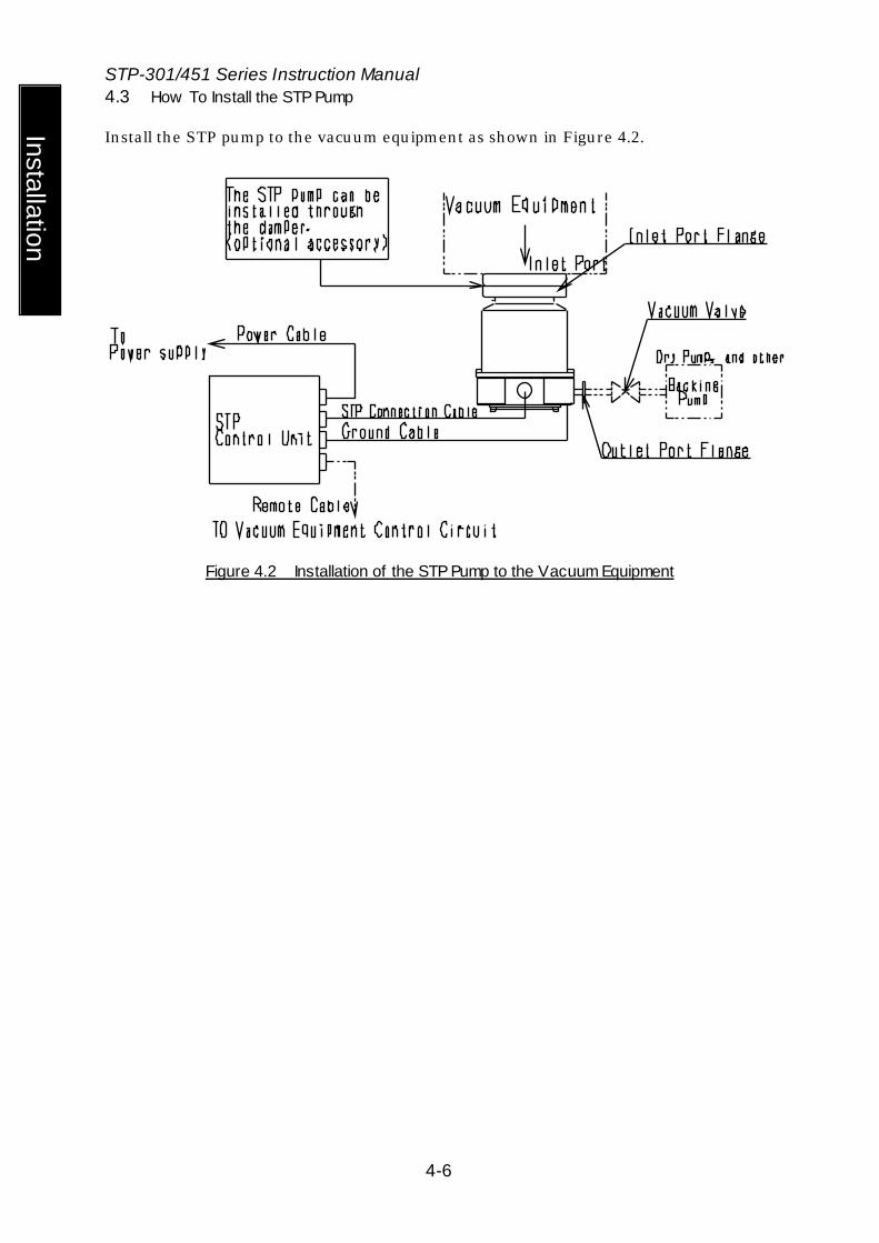
Install the STP pump to the vacuum equipment as shown in Figure 4.2.
Figure 4.2 Installation of the STP Pump to the Vacuum Equipment
STP-301/451 Series Instruction Manual
4-7
Inst
alla
tion
4.3.1 Cleaning the Seal
Inspect the seals of the inlet and outlet port flanges for dirt or oil spots before installing the STP pump to the vacuum equipment. Take the following measures for cleaning the seals:
Clean off with a pure gas. Wipe with proper solvent (such as alcohol).
◇ A splinter shield is attached to the inlet port f lange to prevent foreign particles
from falling into the STP pump. Alw ays leave the splinter shield attached during operation.
◇ The w ipes used for clean the f lange of the pump might become hazardous w aste depending upon the solvent (alcohol). Dispose of the contaminated w ipes appropriately according to the regulations of each national and/or local government.
◇ The splinter shield cannot perfectly prevent foreign particles from falling into the
STP pump. DO NOT install the STP pump in such a manner that foreign particles can easily fall into it (for example, Si w afers or samples are positioned above the STP pump). If installing the STP pump in such a manner, alw ays attach a shield plate w ith suff icient conductance above the STP pump to prevent foreign particles from falling into it. Foreign particles falling into the STP pump through the splinter shield may result in product damage.
◇ Be careful not to scratch the f lange of the STP pump. Check w hether or not there are scratches on the surface, before installing the STP pump.
STP-301/451 Series Instruction Manual
4-8
Installation
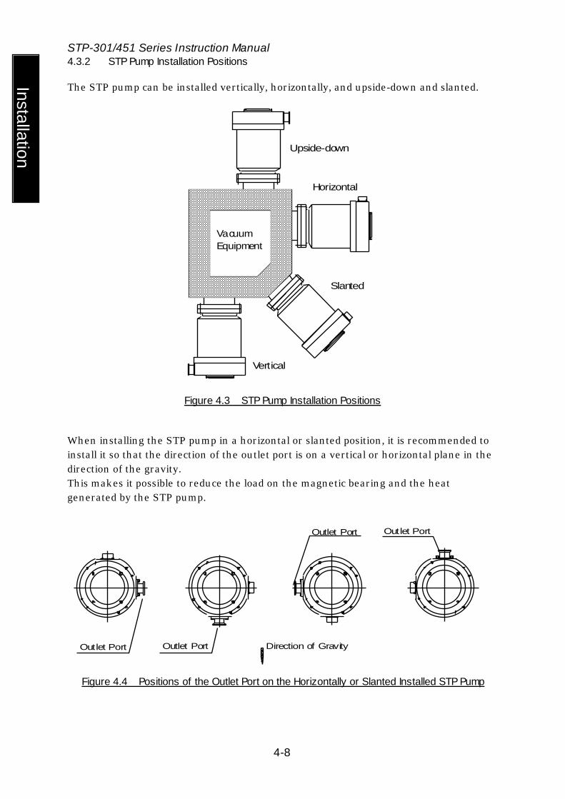
4.3.2 STP Pump Installation Positions
The STP pump can be installed vertically, horizontally, and upside-down and slanted.
VacuumEquipment
Upside-down
Horizontal
Slanted
Vertical
Figure 4.3 STP Pump Installation Positions
When installing the STP pump in a horizontal or slanted position, it is recommended to install it so that the direction of the outlet port is on a vertical or horizontal plane in the direction of the gravity. This makes it possible to reduce the load on the magnetic bearing and the heat generated by the STP pump.
Outlet Port
Outlet Port
Outlet Port
Outlet Port
Direction of Gravity
Figure 4.4 Positions of the Outlet Port on the Horizontally or Slanted Installed STP Pump

STP-301/451 Series Instruction Manual
4-9
Inst
alla
tion
4.3.3 How to Secure the STP Pump
◇ The STP pump is provided w ith a high-speed rotor. The w orst-case failure may
result in a jump in rotational torque leading to personal injury or peripheral equipment damage. The method of securing the STP pump w ill depend on the installation requirements. Secure the STP pump to the vacuum equipment as follow s:
◇ Design and secure the mounting for the STP pump so that it can w ithstand the maximum rotational torque. Refer to Table4.2 for torque in pump abnormality.
◇ In some cases, the damper and the claw clamper securing cannot be used
depend on the type of the STP pump. ◇ Refer to Table 4.1 for tightening torque of the bolt.
Table 4.1 Tightening torque of bolt
Size of bolt Tightening torque of bolt (Nm)M8 12.0 M10 24.1 M12 42.1
◇ When making the leg to secure the base, make them shortened more than ones attached to the STP pump. Use a material that has a tensile strength of 600N/mm2 or more.
◇ When securing the base, use stainless steel securing bolts w ith a tensile strength class is 70 or more.
◇ When using any securing method other than that specif ied in this manual, contact
BOC Edw ards.
Damper
Yes
No
with bolts
with Claw Clamps
Secure the inlet
Refer to "1) When securing the inlet port w ith bolts"
Refer to "2) When securing the inlet port f lange w ith claw clamps"
Refer to "3) When installing the damper in the inlet port f lange"
STP-301/451 Series Instruction Manual
4-10
Installation
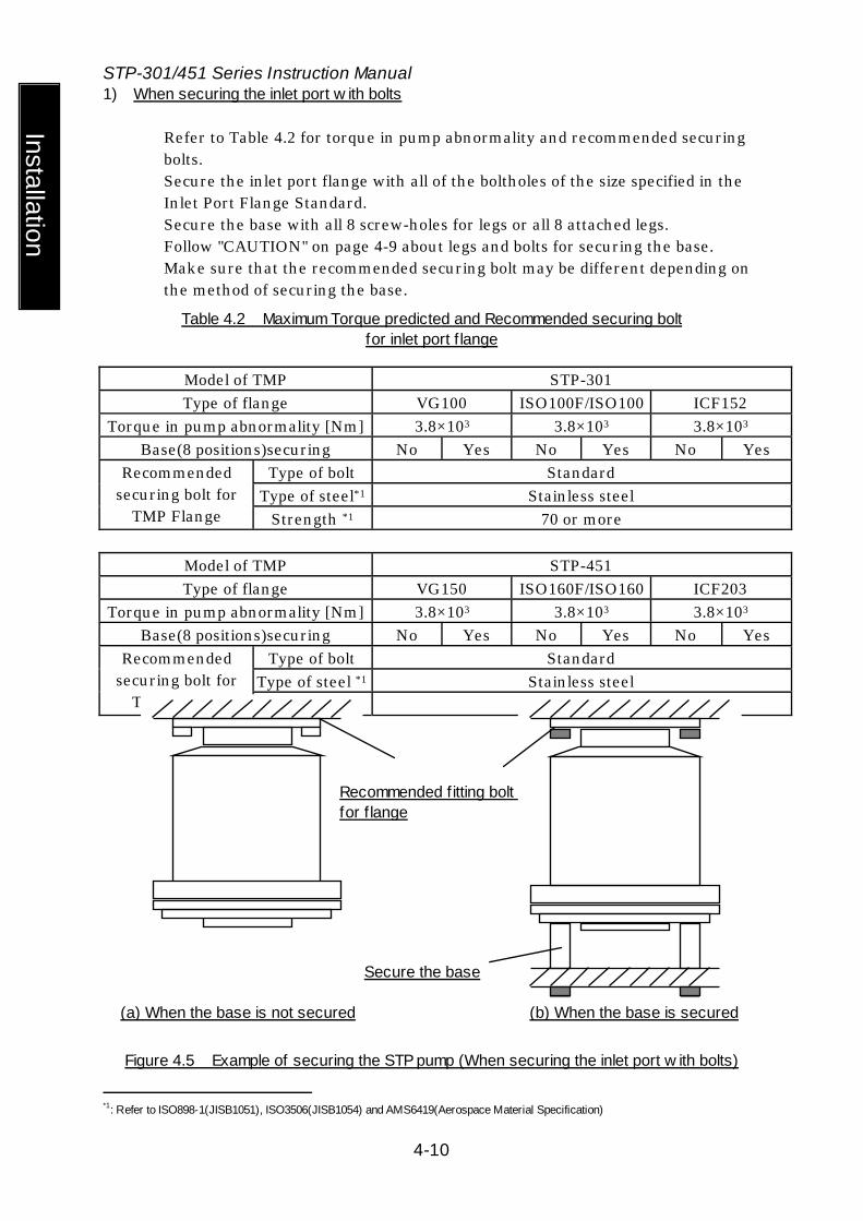
1) When securing the inlet port w ith bolts
Refer to Table 4.2 for torque in pump abnormality and recommended securing bolts. Secure the inlet port flange with all of the boltholes of the size specified in the Inlet Port Flange Standard. Secure the base with all 8 screw-holes for legs or all 8 attached legs. Follow "CAUTION" on page 4-9 about legs and bolts for securing the base. Make sure that the recommended securing bolt may be different depending on the method of securing the base.
Table 4.2 Maximum Torque predicted and Recommended securing bolt for inlet port f lange
Model of TMP STP-301 Type of flange VG100 ISO100F/ISO100 ICF152
Torque in pump abnormality [Nm] 3.8×10³ 3.8×10³ 3.8×10³ Base(8 positions)securing No Yes No Yes No Yes
Type of bolt Standard Type of steel*1 Stainless steel
Recommended securing bolt for
TMP Flange Strength *1 70 or more Model of TMP STP-451 Type of flange VG150 ISO160F/ISO160 ICF203
Torque in pump abnormality [Nm] 3.8×10³ 3.8×10³ 3.8×10³ Base(8 positions)securing No Yes No Yes No Yes
Type of bolt Standard Type of steel *1 Stainless steel
Recommended securing bolt for
TMP Flange Strength *1 70 or more
Figure 4.5 Example of securing the STP pump (When securing the inlet port w ith bolts)
*1: Refer to ISO898-1(JISB1051), ISO3506(JISB1054) and AMS6419(Aerospace Material Specification)
(a) When the base is not secured (b) When the base is secured
Recommended f itting bolt for f lange
Secure the base

STP-301/451 Series Instruction Manual
4-11
Inst
alla
tion
2) When securing the inlet port f lange w ith claw clamps
Refer to Table 4.2 for rotational torque. When securing the inlet port flange with only the claw clamp, the vacuum equipment cannot withstand the maximum rotational torque generated by the worst-case failure. To make the vacuum equipment withstand abnormal torque, secure the base with all 8 screw-holes for legs or all 8 attached legs. Follow "CAUTION" on page 4-9 about legs and bolts for securing the base. For the claw clamp-type, use the required number of claw clamps as specified in Table 4.3. Position the claw clamps evenly on the circumference.
Table 4.3 Number of Claw Clamps by Size of Flange
Size of Flange Number of Claw Clamps ISO 160 or less 4 or more ISO 200 to 250 6 or more ISO 320 or more 8 or more
Figure 4.6 Example of securing the STP pump (When securing the inlet port f lange w ith claw clamps)
Claw Clamps
Secure the base
Vacuum Equipment
STP-301/451 Series Instruction Manual
4-12
Installation
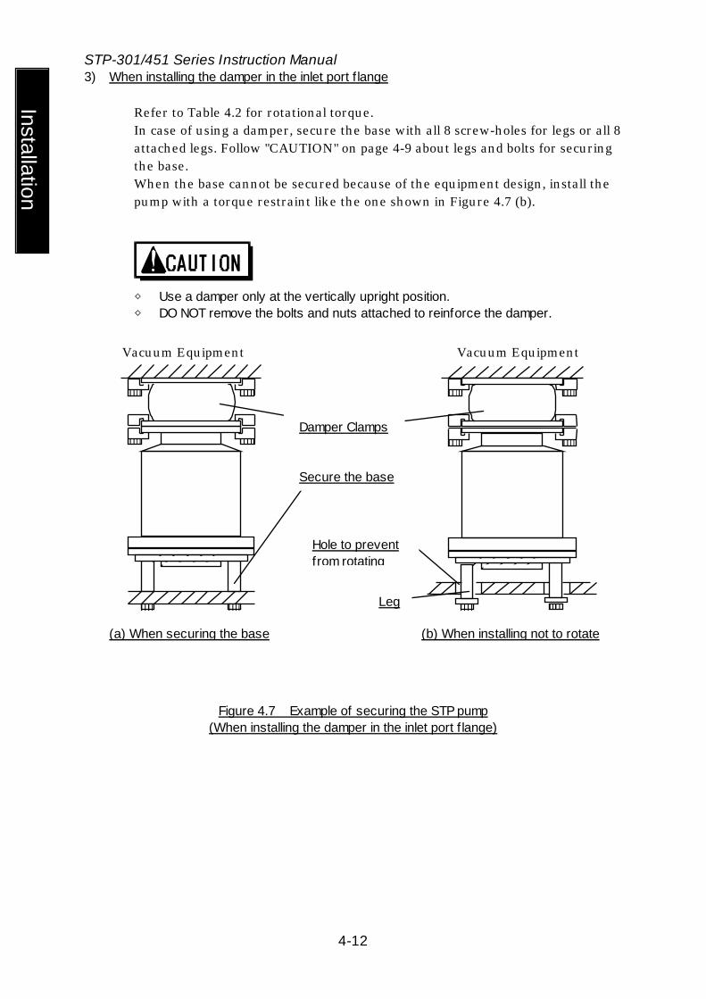
3) When installing the damper in the inlet port f lange
Refer to Table 4.2 for rotational torque. In case of using a damper, secure the base with all 8 screw-holes for legs or all 8 attached legs. Follow "CAUTION" on page 4-9 about legs and bolts for securing the base. When the base cannot be secured because of the equipment design, install the pump with a torque restraint like the one shown in Figure 4.7 (b).
◇ Use a damper only at the vertically upright position. ◇ DO NOT remove the bolts and nuts attached to reinforce the damper.
Figure 4.7 Example of securing the STP pump (When installing the damper in the inlet port f lange)
Vacuum Equipment Vacuum Equipment
Secure the base
Damper Clamps
Hole to prevent from rotating
Leg
(a) When securing the base (b) When installing not to rotate

STP-301/451 Series Instruction Manual
4-13
Inst
alla
tion
4.3.4 Vacuum Piping
◇ DO NOT open the STP pump through the f lange to atmospheric air w hile the STP
pump is running. If atmospheric air f low s into the STP pump, it may not function normally.
◇ Depending upon the type of the backing pump used, atmospheric air may reverse f low into the STP pump w hen the backing pump stops. Attach a vacuum valve to the middle of the piping betw een the STP pump outlet port f lange and the backing pump, and close the vacuum valve w hen the backing pump stops.
In order to let the STP pump bring its performance into full play, follow the precautions below: 1) Be careful not to scratch the flange of the STP pump.
Before installing the STP pump, check whether or not there are scratches on the surface.
2) Use steel or aluminum tubes with a low gas loss to connect the vacuum equipment to the STP pump.
3) Take measures for minimizing leakage. It is also necessary to degrease the tubes as regularly as possible to keep the gas loss as low as possible.
4) It is recommended to use an backing pump of pumping speed 240 L/min or more. However, the pressure at the inlet and outlet ports varies with the flow rate of gas, capacity of the vacuum equipment, length and material of the piping. Select an backing pump in accordance with the capacity and starting method (simultaneous starting, starting after generating roughing vacuum) suitable for the vacuum equipment you use.
5) Connect the STP pump and the backing pump using stainless steel or aluminum alloy tubing, flexible tubing, vacuum rubber or Teflon tubing, and other. The following measures can be used to avoid the transmission of the vibration of the backing pump to the STP pump and the vacuum equipment. • DO NOT place the backing pump on the same floor as the vacuum equipment. • Locate the backing pump on a vibration-proof table.
Attain 1/3 or less of the rotational speed of the backing pump, when adjusting the inherent frequency of the backing pump installed on a vibration-proof table.
• Attach a weight to the piping from the backing pump, or secure the piping to a rigid, heavy object free of vibration.
• Use a tube of high flexibility. 6) Depending upon the type of the backing pump used, oil may contaminate the inside
of the STP pump. Some oil viscosity could cause a malfunction when there is a strong reverse flow of oil. Take the following measures to ensure the correct flow of oil: • Attach a vacuum valve to the middle of the piping between the STP pump outlet
port flange and the backing pump. • Attach an absorption trap adjacent to the vacuum valve.

STP-301/451 Series Instruction Manual
4-14
Installation
Piping at the Inlet Port Flange Attach the inlet port to the high vacuum side. Maximum working pressure: 6.7×10⁻² Pa[5×10⁻⁴
Torr] Pressure at the inlet port flange
applicable continuously (for natural air cooled)
Piping at the Outlet Port Flange Attach the outlet port to the inlet port flange of the backing pump (primary side pump). Allowable backing pressure: 13 Pa[0.1 Torr] Pressure at the outlet port flange
applicable continuously (for natural air cooled)
◇ To attain the ultimate pressure show n in Table 13.1,"STP Pump specif ications,"
set the pressure at the outlet port f lange to 1.3 Pa (10-2 Torr). 4.3.5 Connecting the Ground Cable
Connect the ground cable (yellow/green) between the ground terminal of the STP pump and the ground terminal of the STP control unit. When the resistance between the ground terminals is lower than 0.1 ohms, it is not necessary to connect the ground cable after installing the STP pump and the STP control unit.
◇ When the resistance betw een the ground terminals is over 0.1 ohms, alw ays
connect the ground cable.
STP-301/451 Series Instruction Manual
4-15
Inst
alla
tion
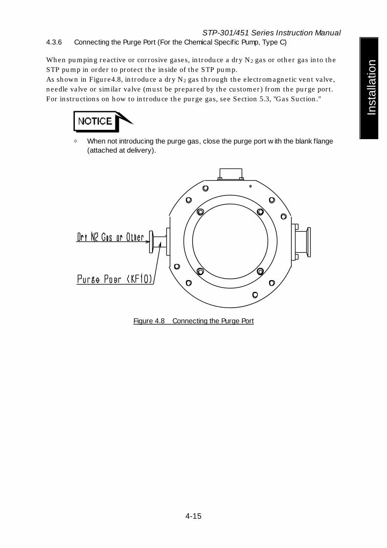
4.3.6 Connecting the Purge Port (For the Chemical Specif ic Pump, Type C)
When pumping reactive or corrosive gases, introduce a dry N2 gas or other gas into the STP pump in order to protect the inside of the STP pump. As shown in Figure4.8, introduce a dry N2 gas through the electromagnetic vent valve, needle valve or similar valve (must be prepared by the customer) from the purge port. For instructions on how to introduce the purge gas, see Section 5.3, "Gas Suction."
◇ When not introducing the purge gas, close the purge port w ith the blank f lange
(attached at delivery).
Figure 4.8 Connecting the Purge Port
5 Baking, Cooling the STP Pump and Gas Pumping 5.1 Baking the STP Pump
To attain a lower pressure in a shorter time and reduce the exhaust time, bake the vacuum equipment and STP pump.
◇ The surfaces of the STP pump and its peripheral equipment w ill become
extremely hot w hen performing baking. NEVER touch them w ith bare hands.
◇ When baking the STP pump, alw ays cool it to prevent overheating. ◇ Start baking after cooling is started.
Set the temperature of the baking heater to 120 °C or low er (an optional baking heater is set to 110 °C or low er).
◇ DO NOT pump gases during baking to prevent overheating.
◇ To exhaust the gas discharged from the vacuum equipment and the inner w all of
the STP pump, run the STP pump during baking. 5.1.1 Attaching a Baking Heater
1) Attach a baking heater (optional accessory) as near as possible to the inlet port flange.
2) Affix the "Hot Surface Warning Label" to the surface of the STP pump so that the operator can see it clearly at any time. (See Figure 5.1, "Attaching Positions of the Cooling Unit and Baking Heater")
◇ Check the rated voltage of the baking heater before use. (The range of the
available voltage of the baking heater (special accessory) is display voltage +/-10%.)
◇ Wind the baking heater around the surface of the STP pump tightly. If the baking heater is not w ound tightly, the loose parts w ill overheat.
◇ Procure protective parts for the baking heater, such as circuit breaker and fuses w hen using the baking heater.
◇ DO NOT apply excessive force to the cable for the baking heater.
5.2 Cooling the STP Pump There are two methods for cooling: Water cooling and Air cooling. When performing baking, cool the STP pump. Also, when pumping gases, cool the STP pump as well. Select the best method which fits your vacuum equipment. 5.2.1 Water Cooling Method
When cooling the STP pump by water cooling, use a water cooling unit (optional accessory). Attach the water cooling unit using 4 screws at screw holes for legs (8-M8*1, depth 16 mm). (For the positions of the screw holes for legs, see "External Appearance of the STP Pump.") 1) Connect the cooling water pipe to the cooling water port in accordance with Figure
5.1. 2) The female screw PT*1 (RC)1/4 is used in the cooling water port. 3) Use the connection hose of ID (internal diameter) 8 mm, and secure it to prevent
water leakage. 4) Use cooling water under the following conditions:
Amount of water: 2 L/min. Temperature: 5 to 25 °C Water pressure: 2.9 x 10⁵ Pa (3 kgf/cm2) or lower
◇ Use clean w ater as much as possible.
Cooling w ater containing foreign materials may corrode or clog the cooling w ater pipe. When the cooling system is clogged w ith foreign materials, clogs may possibly be removed by feeding cooling w ater reversibly.
◇ When the STP pump is overheated due to shortage or suspension of w ater, the protective function detects the overheated condition in the STP pump and stops the STP pump. As a further safety procedure, attach a f low sw itch to the cooling w ater exit so that the STP pump stops if abnormal cooling w ater f low occurs (a f low sw itch is available on the market).
◇ When the STP pump is not to be used for a long period of time or it is to be moved after use, introduce compressed air from one side of the inlet/outlet port so that no w ater w ill remain inside.
◇ The joint for the w ater cooling unit is made of brass. To prevent corrosion, connect the brass joint.
*1: JIS

5.2.2 Air Cooling Method
When water cooling is not available, use an air cooling unit (optional accessory). Attach the air cooling unit using 4 screws at screw holes for legs (8-M8*1, depth 16 mm). (For the positions of the screw holes for legs, see "External Appearance of the STP Pump")
◇ Since the air cooling unit is attached using 4 screw holes for legs, the base for
securing the STP pump cannot be installed using screw holes for legs (see Section 4.3.3, " How to Secure the STP Pump"). When using the air cooling unit, design your vacuum equipment so that the STP pump installing f lange at the vacuum equipment side can w ithstand the torque generated by the abnormal STP pump.
◇ Check the rated voltage of the air cooling unit before use. ◇ Procure a breaker or fuses for the air cooling unit (remote terminal block TB1
incorporates fuses). ◇ When connecting the pow er for the air cooling unit to the remote terminal block
(I/O TB1), attach a metallic cover or a similar part to the terminal block to ensure the safety.
◇ DO NOT apply excessive force to the cable for the air cooling unit. Follow the steps below to run the STP pump associated with the air cooling unit (read through Section 8, "Remote Input/Output Signal Terminal Blocks," then operate them.) 1) Connect the power cable of the air cooling unit between "I/O TB1 FAN OUT
Terminals (3)-(4)." 2) Input the power supply for the air cooling unit between "I/O TB1 AC. POWER IN
Terminals (1)-(2)." 3) The air cooling unit functions under the "ACCELERATION" or "NORMAL
OPERATION" state. 4) The air cooling unit stops when the STP pump stops.
5.3 Gas Suction
◇ When pumping gases, they may remain in the STP pump.
Introduce a purge gas and then exhaust all gasses. Residual gases in the STP pump may cause an accident w hen the STP pump is removed. Confirm the characteristics of gases to be used, referring to the Material Safety Data Sheet (MSDS) you obtain from the gas supplier.
◇ Chlorine or f luorine system gases can be used in the chemical specif ic pump
(type C). When you use gases including alkaline metals, but excluding Li, gases including Ga, Hg, In, or Sn, or HBr, contact BOC Edw ards.
◇ NEVER use corrosive gases (chlorine, f luorine, or other system gases) in the STP-301/STP-451 pump or other models w ithout anti-corrosion treatment.
◇ Cool the STP pump to prevent the STP pump from overheating w hen pumping gases.
5.3.1 How to Introduce a Purge Gas [For Chemical Specif ic Pump (Type C)]
◇ When pumping reactive or corrosive gases, introduce a purge gas to protect the
inside of the STP pump. Doing so may result in product damage. Connect a needle valve or a similar part to the purge port and introduce a dry N2 gas or other gas to perform a gas purge (see Section 4.3.6, "Connecting the Purge Port").
◇ The proper amount of the gas purge is approx. 1.7x10⁻² Pa·m3/sec (10SCCM). ◇ The allow able gas pressure ranges from zero [atmospheric pressure] to
4.8x10⁴Pa [gauge pressure] (zero [atmospheric pressure] to 0.5 kgf/cm2 [gauge pressure]).
◇ When not using the purge port, alw ays mount the blank f lange (attached at delivery).
◇ High-pressure at the inlet port may result in a noise. This is no abnormality/error.
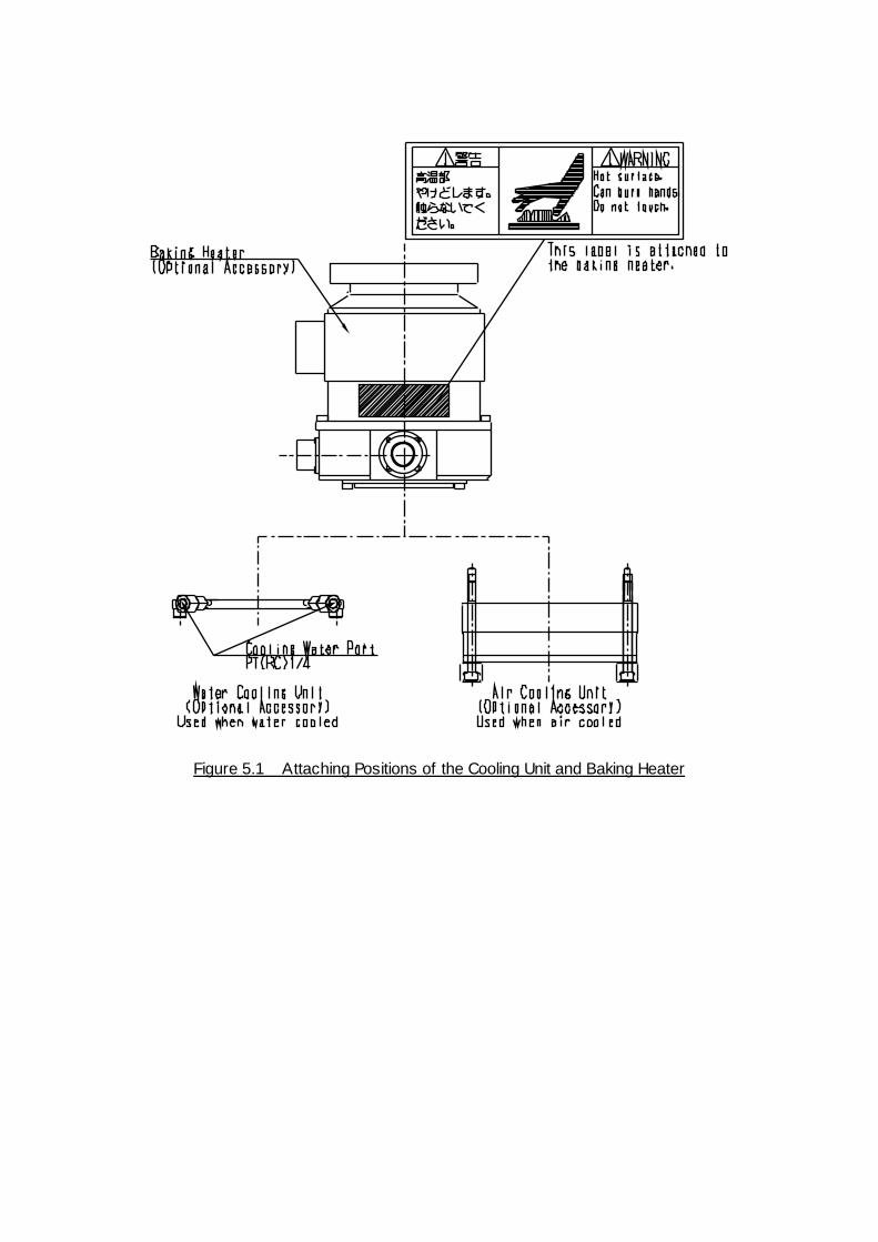
Figure 5.1 Attaching Positions of the Cooling Unit and Baking Heater
STP-301/451 Series Instruction Manual
6-1
Inst
alla
tion
6 Installation of the STP Control Unit 6.1 Name and Function of Each Part
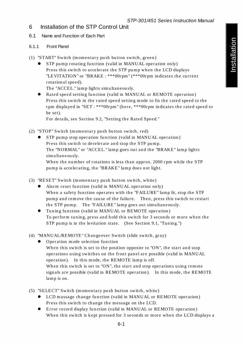
6.1.1 Front Panel
(1) "START" Switch (momentary push button switch, green) STP pump rotating function (valid in MANUAL operation only)
Press this switch to accelerate the STP pump when the LCD displays "LEVITATION" or "BRAKE : ***00rpm" (***00rpm indicates the current rotational speed). The "ACCEL." lamp lights simultaneously.
Rated speed setting function (valid in MANUAL or REMOTE operation) Press this switch in the rated speed setting mode to fix the rated speed to the rpm displayed in "SET : ***00rpm" (here, ***00rpm indicates the rated speed to be set). For details, see Section 9.2, "Setting the Rated Speed."
(2) "STOP" Switch (momentary push button switch, red)
STP pump stop operation function (valid in MANUAL operation) Press this switch to decelerate and stop the STP pump. The "NORMAL" or "ACCEL." lamp goes out and the "BRAKE" lamp lights simultaneously. When the number of rotations is less than approx. 2000 rpm while the STP pump is accelerating, the "BRAKE" lamp does not light.
(3) "RESET" Switch (momentary push button switch, white)
Alarm reset function (valid in MANUAL operation only) When a safety function operates with the "FAILURE" lamp lit, stop the STP pump and remove the cause of the failure. Then, press this switch to restart the STP pump. The "FAILURE" lamp goes out simultaneously.
Tuning function (valid in MANUAL or REMOTE operation) To perform tuning, press and hold this switch for 3 seconds or more when the STP pump is in the levitation state. (See Section 9.1, "Tuning.")
(4) "MANUAL/REMOTE" Changeover Switch (slide switch, gray)
Operation mode selection function When this switch is set to the position opposite to "ON", the start and stop operations using switches on the front panel are possible (valid in MANUAL operation). In this mode, the REMOTE lamp is off. When this switch is set to "ON", the start and stop operations using remote signals are possible (valid in REMOTE operation). In this mode, the REMOTE lamp is on.
(5) "SELECT" Switch (momentary push button switch, white) LCD massage change function (valid in MANUAL or REMOTE operation)
Press this switch to change the message on the LCD. Error record display function (valid in MANUAL or REMOTE operation)
When this switch is kept pressed for 3 seconds or more when the LCD displays a

STP-301/451 Series Instruction Manual
6-2
Installation
pump's operation state ("LEVITATION", "ACCEL." and other.) or the pump's temperature, the LCD displays the operating hours (cumulative) or an error message which occurred in the past. (See Section 11, "Troubleshooting, Maintenance and Inspection.")
(6) LCD
The LCD displays a pump's operation state, speed, or other messages. The LCD displays an error message when an abnormality occurs in the STP
pump. (7) "ACCEL." Lamp (green LED)
Lights during acceleration (ACCELERATION state). (8) "NORMAL" Lamp (green LED)
Lights during rated speed operation (NORMAL OPERATION state). (9) "BRAKE" Lamp (yellow LED)
Lights during deceleration (BRAKE state).
(10) "POWER" Lamp (green LED) Lights while the power is ON. Goes out while the backup power is being supplied.
(11) "FAILURE" Lamp (red LED)
Lights when any of the following abnormalities occurs. The LCD displays an error message simultaneously.
a) When the inside of the STP control unit overheats (70°C or more inside the circuit);
b) When the inside of the STP pump overheats (110°C or more inside the motor or electromagnet);
c) When the motor driver overloads; d) When a power failure occurs; e) When the STP connection cable is not connected; f) When vibration impact is continuously applied to the rotor causing it to
come into contact with the touch down bearing. (12) "REMOTE" Lamp (green LED)
This lamp is on while the operation mode is remote.
STP-301/451 Series Instruction Manual
6-3
Inst
alla
tion (6) (5)
(1) (2) (3)
(7) (8) (9)
(10) (11) (12)
(4)
Figure 6.1 STP Control Unit Front Panel

STP-301/451 Series Instruction Manual
6-4
Installation
6.1.2 Rear Panel
◇ A hazardous live voltage may exist at connector/terminal that marked .
DO NOT touch the terminal. Doing so may result in electric shock. When operating connection/disconnection to connector, alw ays pow er OFF the STP pump (Sw itch the breaker "OFF").
(13) AC POWER Connector (CON1)
A maximum voltage: Equal to the input voltage of this connector. (MAX 240VAC) For primary power input.
(14) MAIN POWER Breaker
Switches ON/OFF the primary power. A metal fitting is attached to secure the breaker at the OFF position.
(15) P. CONNECTOR (CON2)
A maximum voltage: 62VAC For connection of the STP connection cable.
(16) Ground Terminal
For connection of the ground cable between the STP pump and the STP control unit.
(17) I/O TB1 Terminal Block
A maximum voltage: Equal to the input voltage of this connector. (MAX 240VAC) For remote output signals.
(18) I/O TB2 Terminal Block
A maximum voltage: Equal to the input voltage of this connector. (MAX 240VAC) For remote input signals.
(19) F1 Fuse(250 V,10 A) (20) F2 Fuse(250 V,10 A)
For protection of optional power supply for the I/O TB1 terminal block.
(21) CON 4 Connector (Optional accessory) A maximum voltage: Equal to the input voltage of this connector. (MAX 125VAC) For remote input/output signals.
This connector can maintain compatibility with the remote I/O signal of the STP-200/300/400 series.

STP-301/451 Series Instruction Manual
6-5
Inst
alla
tion
(13)
(14) (15)
(16)
(17)
(18)
(19) (20)
(21)
Figure 6.2 STP Control Unit Rear Panel
STP-301/451 Series Instruction Manual
6-6
Installation
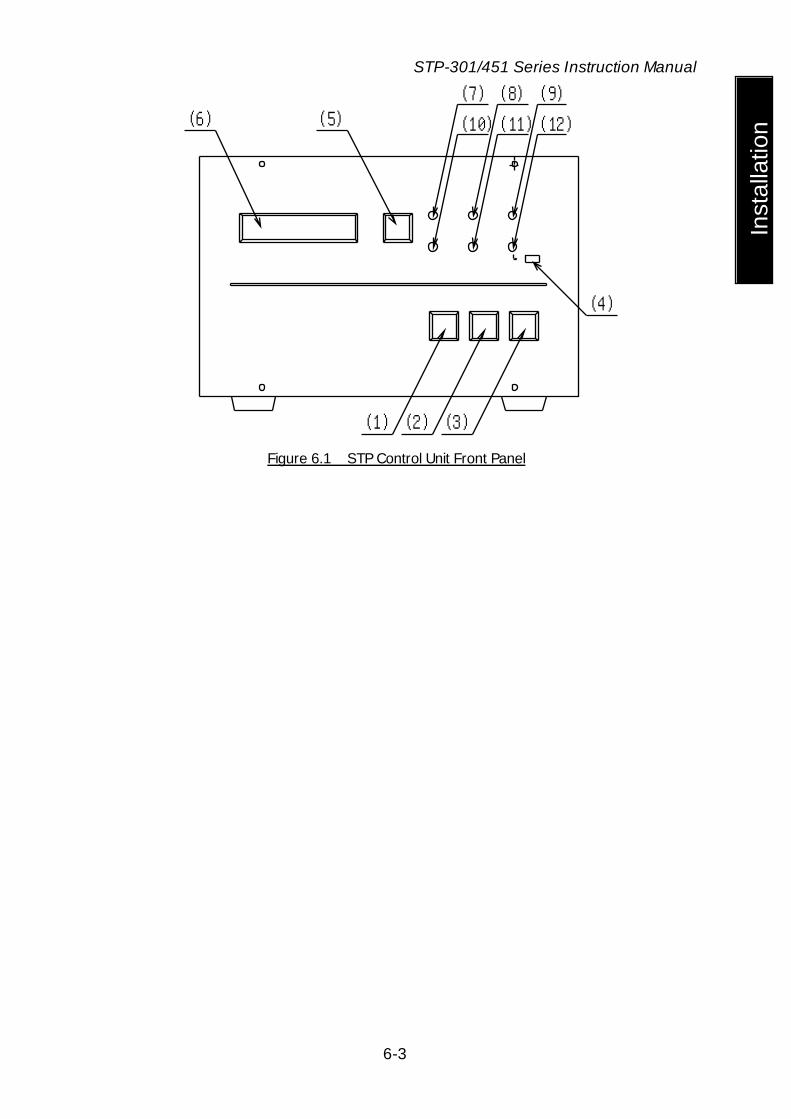
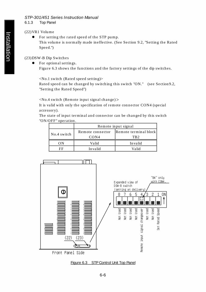
6.1.3 Top Panel
(22) VR1 Volume For setting the rated speed of the STP pump.
This volume is normally made ineffective. (See Section 9.2, "Setting the Rated Speed.")
(23) DSW-B Dip Switches
For optional settings. Figure 6.3 shows the functions and the factory settings of the dip switches.
<No.1 switch (Rated speed setting)> Rated speed can be changed by switching this switch "ON." (see Section9.2, "Setting the Rated Speed") <No.4 switch (Remote input signal change)> It is valid with only the specification of remote connector CON4 (special accessory). The state of input terminal and connector can be changed by this switch "ON/OFF" operation.
Remote input signal
No.4 switch Remote connector CON4
Remote terminal block TB2
ON Valid Invalid FF Invalid Valid
(22) (23)
Front Panel Side
8 7 6 5 4 3 2 1 ON
Not Used
Remote input signal changeover
Set Rated Speed
Expanded view of DSW-B switch(setting at delivery)
"ON" onlywith CON4.
Not Used
Not Used
Not Used
Not Used
Not Used
Figure 6.3 STP Control Unit Top Panel

STP-301/451 Series Instruction Manual
6-7
Inst
alla
tion
6.1.4 Side Panel (Left)
(24) Air Cooling Fan For cooling the inside of the STP control unit.
(24)
Figure 6.4 STP Control Unit Side Panel (Left)
STP-301/451 Series Instruction Manual
6-8
Installation
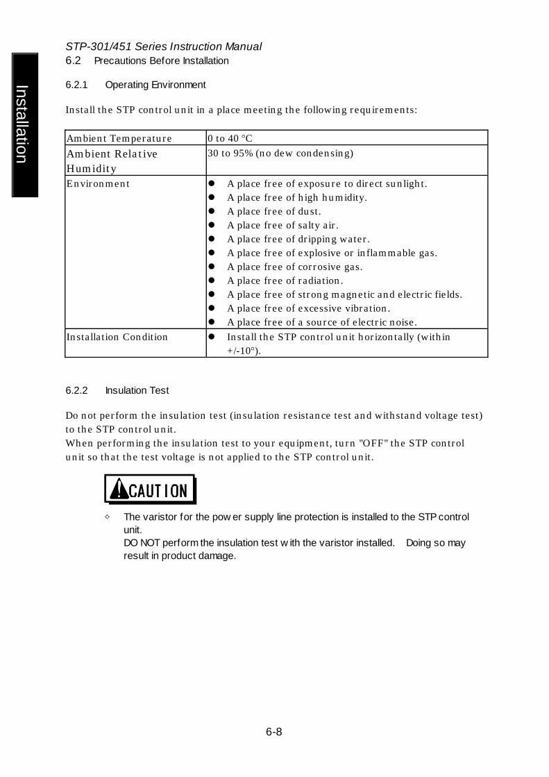
6.2 Precautions Before Installation
6.2.1 Operating Environment
Install the STP control unit in a place meeting the following requirements: Ambient Temperature 0 to 40 °C Ambient Relative Humidity
30 to 95% (no dew condensing)
Environment A place free of exposure to direct sunlight. A place free of high humidity. A place free of dust. A place free of salty air. A place free of dripping water. A place free of explosive or inflammable gas. A place free of corrosive gas. A place free of radiation. A place free of strong magnetic and electric fields. A place free of excessive vibration. A place free of a source of electric noise.
Installation Condition Install the STP control unit horizontally (within +/-10°).
6.2.2 Insulation Test
Do not perform the insulation test (insulation resistance test and withstand voltage test) to the STP control unit. When performing the insulation test to your equipment, turn "OFF" the STP control unit so that the test voltage is not applied to the STP control unit.
◇ The varistor for the pow er supply line protection is installed to the STP control
unit. DO NOT perform the insulation test w ith the varistor installed. Doing so may result in product damage.
STP-301/451 Series Instruction Manual
6-9
Inst
alla
tion
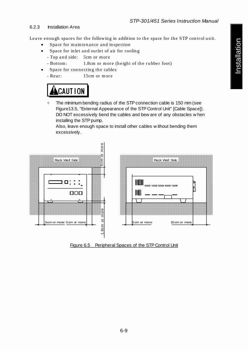
6.2.3 Installation Area
Leave enough spaces for the following in addition to the space for the STP control unit. • Space for maintenance and inspection • Space for inlet and outlet of air for cooling
- Top and side: 5cm or more - Bottom: 1.8cm or more (height of the rubber foot)
• Space for connecting the cables - Rear: 15cm or more
◇ The minimum bending radius of the STP connection cable is 150 mm (see
Figure13.5, "External Appearance of the STP Control Unit" [Cable Space]). DO NOT excessively bend the cables and bew are of any obstacles w hen installing the STP pump. Also, leave enough space to install other cables w ithout bending them excessively.
Rack Wall Side
5cm or more
5cm
orm
ore
1.8c
mor
mor
e
Rack Wall Side
5cm or more 5cm or more 15cm or more
Figure 6.5 Peripheral Spaces of the STP Control Unit
STP-301/451 Series Instruction Manual
6-10
Installation
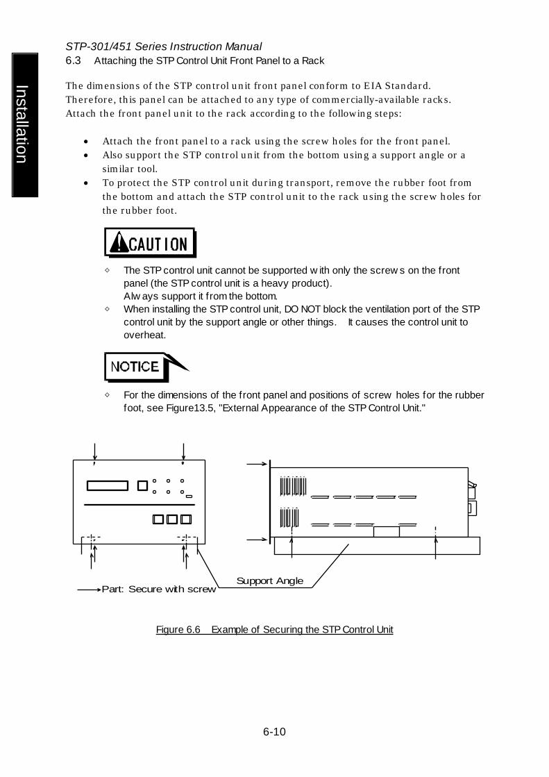
6.3 Attaching the STP Control Unit Front Panel to a Rack
The dimensions of the STP control unit front panel conform to EIA Standard. Therefore, this panel can be attached to any type of commercially-available racks. Attach the front panel unit to the rack according to the following steps:
• Attach the front panel to a rack using the screw holes for the front panel. • Also support the STP control unit from the bottom using a support angle or a
similar tool. • To protect the STP control unit during transport, remove the rubber foot from
the bottom and attach the STP control unit to the rack using the screw holes for the rubber foot.
◇ The STP control unit cannot be supported w ith only the screw s on the front
panel (the STP control unit is a heavy product). Alw ays support it from the bottom.
◇ When installing the STP control unit, DO NOT block the ventilation port of the STP control unit by the support angle or other things. It causes the control unit to overheat.
◇ For the dimensions of the front panel and positions of screw holes for the rubber
foot, see Figure13.5, "External Appearance of the STP Control Unit."
Support AnglePart: Secure with screw
Figure 6.6 Example of Securing the STP Control Unit

STP-301/451 Series Instruction Manual
6-11
Inst
alla
tion
6.4 Cable Connection
6.4.1 Name and Dimensions of Each Cable
STP Control unit Side STP Pump Side
Ground Terminal( )
Crimp-Type Terminal Lug(M4 )*1
Yellow / Green WireL≦20m: 4mm^2L>20m: 10mm^2
φ4.3(L≦20m)φ6.5(L>20m)
Ground Terminal( )
Crimp-Type Terminal Lug(M4 )*1
Unit:mm
Figure 6.7 External Dimensions of Ground Cable
76.5
24.5STP-301/451
Series
40
69.9
44.7
φ16
45pin (Pin) 41pin (Spcket)
Unit:mm
STP Control Unit Side STP Pump Side
L-type Connector
Figure 6.8 External Dimensions of STP Connection Cable
*1 : JIS
STP-301/451 Series Instruction Manual
6-12
Installation
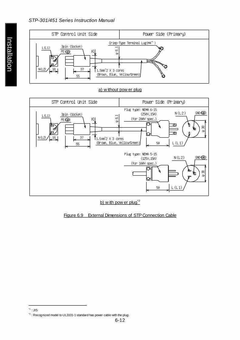
STP Control Unit Side Power Side (Primary)
φ8.1
25
37
55
18
3pin (Socket)Crimp-Type Terminal Lug(M4 )
*1
1.5mm̂ 2 X 3 cores(Brown, Blue, Yellow/Green)
PE( )L(L1)
N(L2)
a) w ithout pow er plug
φ8.1
25
37
55
N(L2)
L(L1)
φ38
N(L2)
L(L1)
18
PE( )L(L1)
N(L2)
Plug type: NEMA 6-15(250V,15A)
(for 200V spec.)
GND( )
Plug type: NEMA 5-15(125V,15A)
(for 100V spec.)
GND( )
50
50
φ38
STP Control Unit Side Power Side (Primary)
3pin (Socket)
1.5mm̂ 2 X 3 cores(Brown, Blue, Yellow/Green)
b) w ith pow er plug*2
Figure 6.9 External Dimensions of STP Connection Cable
*1 : JIS *2 : Recognized model to UL3101-1 standard has power cable with the plug.
STP-301/451 Series Instruction Manual
6-13
Inst
alla
tion
STP-301/451 Series
6.4.2 How to Connect the Cables
◇ When connecting/disconnecting cables, alw ays pow er OFF the STP pump
(sw itch the breaker "OFF"). Failure to do so may result in electric shock or product damage.
◇ With each connector, align the position of the guide key and insert the pin vertically so as not to bend it. If the pin is bent, not only may the connector not function normally, but may make the pins contact each other, resulting in a malfunction.
◇ Lock and securely tighten each connector and screw . ◇ DO NOT apply a voltage to each pin and DO NOT cause any short-circuiting
betw een pins. ◇ Connect each cable securely. DO NOT place heavy objects on the cables nor
bend them excessively. Support each cable so as not to apply direct force to the connectors or terminals. If any problem occurs in cables, connectors or terminals, the STP pump may not function normally.
1) Connecting the Ground Cable Connect the ground cable (yellow/green) between the ground terminal of the STP pump and the ground terminal of the STP control unit. When the resistance between the ground terminals is lower than 0.1 ohms, it is not necessary to connect the ground cable after installing the STP pump and the STP control unit.
◇ First, connect the ground cable. Next, connect other cables. ◇ When the resistance betw een the ground terminals is over 0.1 ohms, alw ays
connect the ground cable. Failure to do so may result in electric shock. 2) Connecting the STP Connection Cable Connect the receptacle side of the STP connection cable to the STP connector of the STP pump and connect the plug side to "P.CONNECTOR CON2" of the STP control unit.
◇ Alw ays use the STP pump and STP control unit of the same model name and
serial number. If you plan to use units having the same model name but different serial numbers or to change the length of the STP connection cable, the tuning is required. To perform the tuning, see Section 9.1, “Tuning.” If the units are used w ithout tuning, they may not operate normally.
STP-301/451 Series Instruction Manual
6-14
Installation
If you plan to use the units having different model names, they may not be used even w hen the tuning is performed. In the latter case, contact service off ice.
◇ Use the STP connection cable that has a label aff ixed The use of different cables may result in product damage.
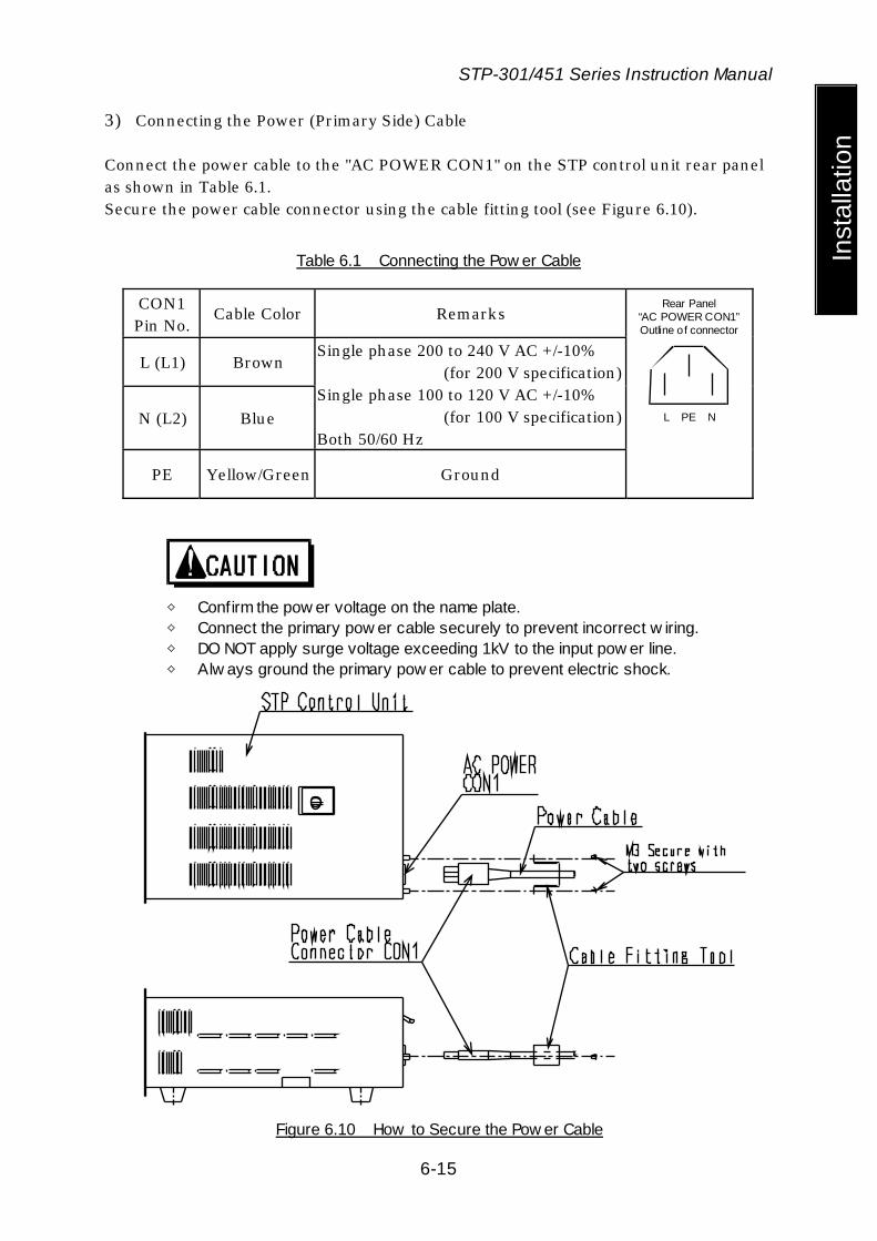
STP-301/451 Series Instruction Manual
6-15
Inst
alla
tion
3) Connecting the Power (Primary Side) Cable Connect the power cable to the "AC POWER CON1" on the STP control unit rear panel as shown in Table 6.1. Secure the power cable connector using the cable fitting tool (see Figure 6.10).
Table 6.1 Connecting the Pow er Cable
CON1 Pin No.
Cable Color Remarks
L (L1) Brown
N (L2) Blue
Single phase 200 to 240 V AC +/-10% (for 200 V specification) Single phase 100 to 120 V AC +/-10% (for 100 V specification) Both 50/60 Hz
PE Yellow/Green Ground
L PE N
Rear Panel “AC POWER CON1” Outline of connector
◇ Confirm the pow er voltage on the name plate. ◇ Connect the primary pow er cable securely to prevent incorrect w iring. ◇ DO NOT apply surge voltage exceeding 1kV to the input pow er line. ◇ Alw ays ground the primary pow er cable to prevent electric shock.
Figure 6.10 How to Secure the Pow er Cable
STP-301/451 Series Instruction Manual
6-16
Installation
Connecting to Semiconductor Equipment
The STP pump is a component system when installing to the semiconductor equipment. Consider the followings when designing the semiconductor equipment. 6.4.3 Connecting to Pow er
The STP control unit receives its power from the semiconductor equipment electrical distribution system via a circuit breaker. Electrical energy isolation (Lockout/Tagout) is achieved by opening the main disconnect device or circuit breaker of the semiconductor equipment, thereby: removing power from the STP pump. Provide the equipment with the main disconnect or circuit breaker devices rated for at least 10,000 Arms symmetrical amperes interrupting capacity (AIC). 6.4.4 Emergency Off Circuit (EMO Circuit)
Activation of EMO circuit of the equipment will interrupt electrical power from the STP control unit. When the power is shut off, the STP pump performs the same as a power failure. (After backup operation of a power failure, the rotor lands on the touch down bearing) Consider the followings when establishing the EMO circuit.
◇ Unite the exhaust gas system to prevent atmosphere from being introduced into
the STP pump w hen the EMO circuit operates. (example: shut the valve) When atmosphere is introduced into the STP pump, the touch dow n bearing may not operate normally.
◇ The STP pump rotates for a w hile after the EMO circuit shuts off the pow er. Perform a recovery operation after the STP pump has stopped completely.
◇ Before performing the operation check of the EMO circuit w ith regular maintenance, stop the STP pump to prevent damage to the touch dow n bearing.
7 How to Start/Stop the STP Pump
◇ NEVER connect or disconnect any cables w hile the pow er is ON. ◇ NEVER turn the primary pow er OFF (sw itch the breaker "OFF") w hile the STP
pump is in rotation. ◇ DO NOT release the inlet port f lange or outlet port f lange into the atmosphere
w hile the STP pump is in rotation. 7.1 Before Starting
After completing the installation, piping, leakage test of the STP pump, installation of the STP control unit, and wiring, the STP pump is ready for start. Check the following items before starting: 1) Are the STP pump and the STP control unit secured according to the appropriate
method? 2) Is the primary power cable connected correctly to the power supply? 3) Is the power voltage selected properly? 4) Are the ground cable and STP connection cable securely connected?
Are each terminal and each connector securely locked? 5) Is the label affixed correctly to the STP connection cable? 6) Is the serial number of the STP pump the same as that of the STP control unit?
If they are different, perform the tuning according to Section 9.1, "Tuning." 7) Did you change the STP connection cable length? If you did, perform the tuning
according to Section 9.1, "Tuning."
STP-301/451 Series

7.2 Start Procedures
Start the backing pump before or simultaneously with the start of the STP pump. Open the vacuum valve located at the outlet port flange side after starting the backing pump.
◇ DO NOT open the vacuum valve w ithout operating the backing pump.
Depending upon the type of the backing pump, doing so may cause a reverse f low of oil, w hich could contaminate the inside of the STP pump.
◇ When start/stop operations are frequently performed, the STP pump may overheat. Avoid doing so.
7.3 Stop Procedures
Close the vacuum valve located at the outlet port flange side just before or after stopping the STP pump. After closing the valve, stop the backing pump.
◇ DO NOT stop the backing pump w ithout closing the vacuum valve. Depending
upon the type of the backing pump, doing so could cause a reverse f low of atmospheric air into the STP pump, w hich may result in a malfunction.
◇ DO NOT stop the backing pump w ithout closing the valve.
Depending upon the type of the backing pump, doing so may cause a reverse f low of oil, w hich could contaminate the inside of the STP pump.

There are two methods of operating the STP pump: MANUAL and REMOTE. Select one which fits your vacuum equipment. 7.4 Manual Operation
Slide the "MANUAL/REMOTE" changeover switch on the STP control unit front panel to the position opposite to "ON." At this time, the "REMOTE" lamp is off. 7.4.1 Pow ering ON
1) Switch "ON" the breaker on the rear panel. (To prevent incorrect operation, a metal fitting is attached to the breaker. Loosen the screw, lift the metal fitting, and secure it.) The magnet bearing functions and the rotor levitates (POWER ON state). The "POWER" lamp lights.
2) The STP control unit executes the self test. If no error is found, the LCD displays "LEVITATION."
7.4.2 Starting the STP Pump
1) Press the "START" switch on the front panel to start and accelerate the STP pump. The "ACCEL." lamp lights. The LCD displays the current rotational speed in "ACCEL: ***00rpm" in units of 500 rpm (ACCELERATION state).
2) When the STP pump attains the rated speed of rotations, the "ACCEL." lamp goes out, and the "NORMAL" lamp lights. Also, the LCD displays "NORMAL: ***00rpm" (NORMAL OPERATION state).
◇ The STP pump can be manually started only w hen the LCD displays
"LEVITATION" or "BRAKE: ***00rpm". In the case of another message displayed, press the "SELECT" sw itch one or more times until "LEVITATION" or "BRAKE: ***00rpm" is displayed.
◇ Although the STP pump sounds for several seconds w hile it is accelerating, this is not an indication of abnormality.
7.4.3 Stopping the STP Pump
1) Press the "STOP" switch on the front panel to stop the STP pump. The "NORMAL" lamp or "ACCEL." lamp goes out, and the "BRAKE" lamp lights (BRAKE state). (The "BRAKE" lamp does not light when the number of rotations is less than 500 rpm.)
2) The "BRAKE" lamp goes out when the number of rotations goes below 500 rpm.

◇ The STP pump can be stopped w ith any message displayed in the LCD.

7.4.4 Starting the STP Pump after Stopping
Press the "START" switch on the front panel to reaccelerate the STP pump. The STP pump can be reaccelerated even while it is stopping.
◇ The STP pump can be reaccelerated only w hen the LCD displays "LEVITATION"
or "BRAKE: ***00rpm." 7.4.5 Pow ering OFF
Switch "OFF" the breaker on the rear panel when all three lamps of "ACCEL.", "NORMAL", and "BRAKE" are off. The magnetic bearing stops, the rotor lands, and the "POWER" lamp goes out (POWER OFF state).
◇ NEVER sw itch OFF the breaker w hen any lamp of "ACCEL.", "NORMAL", and
"BRAKE" is on. Doing so causes such a state as a pow er failure. 7.4.6 Starting the STP Pump after a Safety Function Operates
A safety function operates when an abnormality occurs in the STP pump or peripheral equipment. To restart the STP pump, remove the cause of the abnormality after the "BRAKE" lamp goes out, and press the "RESET" switch. The "FAILURE" lamp goes out and the safety function is released (RESET operation). Then, press the "START" switch. For the safety functions and troubleshooting, see Section 10, "Safety Functions " and Section 11, "Troubleshooting, Maintenance and Inspection."

7.5 Remote Operation (I/O TB2)
(Read through Section 8.2, "I/O TB 2 Terminal Block" before use.) Slide the "MANUAL/REMOTE" changeover switch on the STP control unit front panel to "ON." The "REMOTE" lamp lights. 7.5.1 Pow ering ON
1) Switch "ON" the breaker on the STP control unit rear panel. (To prevent incorrect operation, a metal fitting is attached to the breaker. Loosen the screw, lift the metal fitting, then secure it.) The magnetic bearing functions and the rotor levitates (POWER ON state). The "POWER" lamp lights.
2) The STP control unit executes the self test. If no error is found, the LCD displays "LEVITATION."
7.5.2 Starting/Stopping the STP Pump
There are three methods of starting/stopping the STP pump. Use one of them.
Table 7.1 Starting/Stopping the STP Pump during Remote Operation (I/O TB2)
Method Starting the Pump Stopping the Pump 1 1) With the circuit between (2)-(3) shorted,
short the circuit between (1)-(4). 2) Short the circuit between (4)-(5) for 0.3
seconds or more. However, when inputting the signal simultaneously with switching "ON" the breaker on the rear panel, continue to short the circuit for 5 seconds or more.
Open the circuit between (1)-(4).
2 With the circuit between (2)-(3) shorted, short the circuit between (1)-(5).
Open the circuit between (1)-(5).
3 Input 25 V AC or 12 to 48 V DC between (3)-(5). With DC, the (+) side can be connected to either (3) or (5).
Open the circuit between (3)-(5).
◇ When using method 3 show n in the above table, 25 to 250 V AC can be input.
In this case, attach a metallic cover or a similar part to the terminal block to ensure the safety.

◇ The STP pump can be started by remote operation w ith any message displayed on the LCD.
◇ Although the STP pump sounds for several seconds w hile it is accelerating, this is not an indication of abnormality.

7.5.3 Starting the STP Pump After Stopping
Perform the rotation procedures to reaccelerate the STP pump. See Section 7.5.2, "Starting/Stopping the STP Pump." The STP pump can be reaccelerated even while it is stopping.
◇ The STP pump can be reaccelerated by remote operation w ith any message
displayed on the LCD. 7.5.4 Pow ering OFF
Switch "OFF" the breaker on the rear panel when all three lamps of "ACCEL.", "NORMAL," and "BRAKE" are off. The magnetic bearing stops, the rotor lands, and the "POWER" lamp goes out (POWER OFF state).
◇ NEVER sw itch OFF the breaker w hen any lamp of "ACCEL.", "NORMAL," and
"BRAKE" is on. Doing so causes such a state as a pow er failure. 7.5.5 Starting the STP Pump after a Safety Function Operates
A safety function operates when an abnormality occurs in the STP pump or peripheral equipment. To restart the STP pump, remove the cause of the abnormality after the "BRAKE" lamp goes out, and perform either operation shown in Table 7.2. The "FAILURE" lamp goes out and the safety function is released (RESET operation). Then, start the STP pump. For the safety functions and troubleshooting, see Section 10, "Safety Functions " and Section 11, "Troubleshooting, Maintenance and Inspection."
Table 7.2 Reset Operation during Remote Operation (I/O TB2)
Method Reset Operation 1 With the circuit between (2)-(3) shorted, short the circuit between
(6)-(1) (terminals for reset signal) for 0.3 seconds or more. 2 Input 25 V AC or 12 to 48 V DC between (6)-(3) (terminals for reset
signal) for 0.3 seconds or more. With DC, the (+) side can be connected to either (3) or (6).
◇ When using method 2 show n in the above table, 25 to 250 V AC can be input.
In this case, attach a metallic cover or a similar part to the terminal block to

ensure the safety.
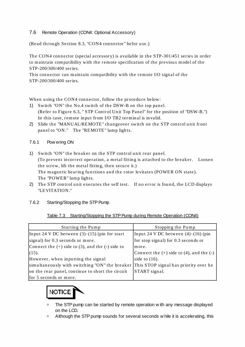
7.6 Remote Operation (CON4: Optional Accessory)
(Read through Section 8.3, "CON4 connector" befor use.) The CON4 connector (special accessory) is available in the STP-301/451 series in order to maintain compatibility with the remote specification of the previous model of the STP-200/300/400 series. This connector can maintain compatibility with the remote I/O signal of the STP-200/300/400 series. When using the CON4 connector, follow the procedure below: 1) Switch "ON" the No.4 switch of the DSW-B on the top panel.
(Refer to Figure 6.3, " STP Control Unit Top Panel" for the position of "DSW-B.") In this case, remote input from I/O TB2 terminal is invalid.
2) Slide the "MANUAL/REMOTE" changeover switch on the STP control unit front panel to "ON." The "REMOTE" lamp lights.
7.6.1 Pow ering ON
1) Switch "ON" the breaker on the STP control unit rear panel. (To prevent incorrect operation, a metal fitting is attached to the breaker. Loosen the screw, lift the metal fitting, then secure it.) The magnetic bearing functions and the rotor levitates (POWER ON state). The "POWER" lamp lights.
2) The STP control unit executes the self test. If no error is found, the LCD displays "LEVITATION."
7.6.2 Starting/Stopping the STP Pump
Table 7.3 Starting/Stopping the STP Pump during Remote Operation (CON4)
Starting the Pump Stopping the Pump Input 24 V DC between (3)‐(15) (pin for start signal) for 0.3 seconds or more. Connect the (+) side to (3), and the (-) side to (15). However, when inputting the signal simultaneously with switching "ON" the breaker on the rear panel, continue to short the circuit for 5 seconds or more.
Input 24 V DC between (4)‐(16) (pin for stop signal) for 0.3 seconds or more. Connect the (+) side to (4), and the (-) side to (16). This STOP signal has priority over he START signal.
◇ The STP pump can be started by remote operation w ith any message displayed
on the LCD. ◇ Although the STP pump sounds for several seconds w hile it is accelerating, this
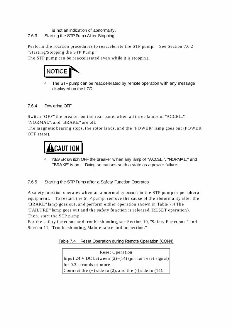
is not an indication of abnormality. 7.6.3 Starting the STP Pump After Stopping
Perform the rotation procedures to reaccelerate the STP pump. See Section 7.6.2 "Starting/Stopping the STP Pump." The STP pump can be reaccelerated even while it is stopping.
◇ The STP pump can be reaccelerated by remote operation w ith any message
displayed on the LCD. 7.6.4 Pow ering OFF
Switch "OFF" the breaker on the rear panel when all three lamps of "ACCEL.", "NORMAL", and "BRAKE" are off. The magnetic bearing stops, the rotor lands, and the "POWER" lamp goes out (POWER OFF state).
◇ NEVER sw itch OFF the breaker w hen any lamp of "ACCEL.", "NORMAL," and
"BRAKE" is on. Doing so causes such a state as a pow er failure. 7.6.5 Starting the STP Pump after a Safety Function Operates
A safety function operates when an abnormality occurs in the STP pump or peripheral equipment. To restart the STP pump, remove the cause of the abnormality after the "BRAKE" lamp goes out, and perform either operation shown in Table 7.4 The "FAILURE" lamp goes out and the safety function is released (RESET operation). Then, start the STP pump. For the safety functions and troubleshooting, see Section 10, "Safety Functions " and Section 11, "Troubleshooting, Maintenance and Inspection."
Table 7.4 Reset Operation during Remote Operation (CON4)
Reset Operation Input 24 V DC between (2)‐(14) (pin for reset signal) for 0.3 seconds or more. Connect the (+) side to (2), and the (-) side to (14).
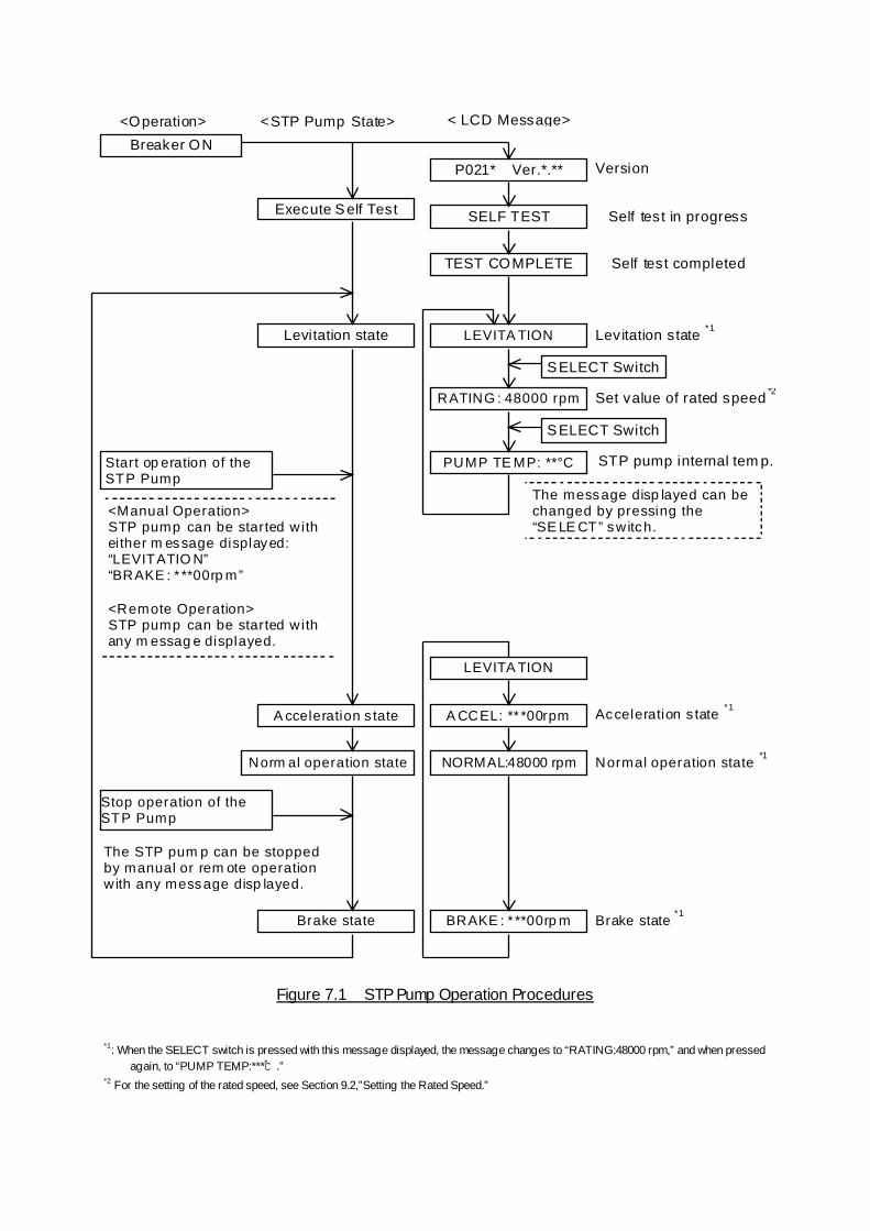
NORMAL:48000 rpm
BRAKE : * **00rp m
RATING : 48000 rpm
LEVITA TION
Brake state
The STP pum p can be stopped by manual or rem ote operation w ith any message disp layed.
Stop operation of the STP Pump
A CCEL: ** *00rpm
LEVITA TION
Norm al operation state
A cceleration s tate
PUMP TE MP: **°C
<Manual Operation> STP pump can be started w ith ei ther m essage displayed: “LEVITATIO N” “BRAKE : * **00rp m” <Remote Operation> STP pump can be started w ith any m essag e displayed.
Start op eration of the STP Pump
Brake state *1
Normal operation state *1
Acceleration s tate *1
The message disp layed can be changed by pressing the “SE LE CT” switch.
STP pump internal tem p.
Set value of rated speed *2
Levitation state *1
Self test completed
Self test in progress
Version
< LCD Message> <STP Pump State> <Operation>
Levitation state
TEST COMPLETE
SELF TEST Execute Self Test
P021* Ver.*.**
Breaker ON
SELECT Switch
SELECT Switch
Figure 7.1 STP Pump Operation Procedures
*1: When the SELECT switch is pressed with this message displayed, the message changes to “RATING:48000 rpm,” and when pressed
again, to “PUMP TEMP:***℃.” *2 For the setting of the rated speed, see Section 9.2,”Setting the Rated Speed.”

STP-301/451 Series Instruction Manual
Operation
8 Remote Input/Output Signal Terminal Blocks 8.1 I/O TB1 Terminal Block
This is a terminal block for remote output signals. Use it in accordance with Table 8.1 and Figure 8.1. This terminal block functions in both the MANUAL and REMOTE operations. The screw for the terminal is M3.5*1. Five abbreviations are used in the following table:
N.O: Normal Open N.C: Normal Close COM: Common IN: Input Terminal OUT: Output Terminal
◇ When connecting the pow er supply for the air cooling unit to terminals (1)-(4),
attach a metallic cover or a similar part to the terminal block to ensure the safety.
Table 8.1 I/O TB1 Terminal Block
Terminal Description AC.POWER
N1 IN L1
(1)
(2)
Terminals for inputting power for driving the air cooling unit. The voltage input to these terminals is output to the specified terminal block through operation of the STP pump.
FAN
N.O OUT(4)
(3)
Terminals for connecting the air cooling unit. The voltage input to AC. POWER terminals ((1)-(2)) is output to these terminals when the STP pump is in acceleration or rated operation. The voltage is cut OFF when the STP pump is under the BRAKE state (see Section 5.2.2, "Air Cooling Method").
(6)
(5)
Not-used. DO NOT use these terminals.
POWER
N.O OUT(8)
(7)
Terminals for outputting the POWER ON state signal. These terminals are closed when the magnetic bearing functions and the rotor levitates. This signal is cut OFF at a power failure.
COM
N.O N.C
ALARMOUT
(9)
(10)
(11)
Terminals for outputting the ALARM signal. When an abnormality/error is detected under the POWER ON state, the terminals between (10)-(9) are closed, and the terminals between (10)-(11) are opened. However, when the rotational speed is less than 20,000rpm during power failure backup operation, this signal is not output.
*1: JIS
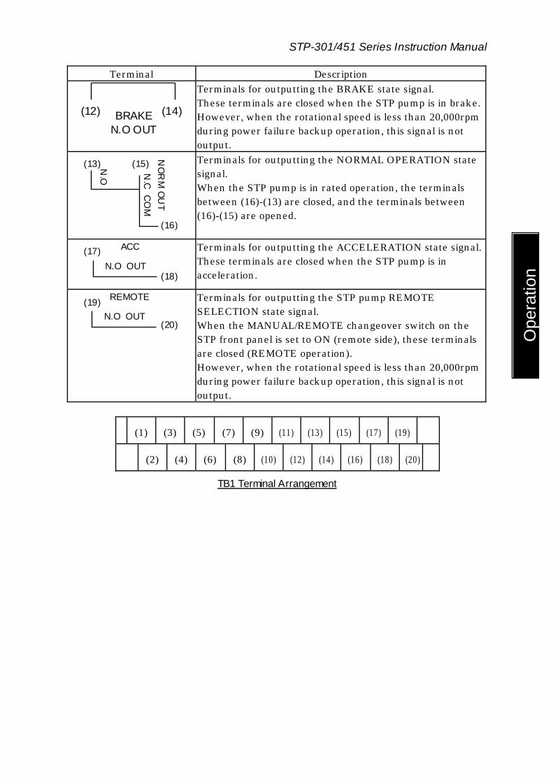
STP-301/451 Series Instruction Manual
Ope
ratio
n
Terminal Description
BRAKEN.O OUT
(12) (14)
Terminals for outputting the BRAKE state signal. These terminals are closed when the STP pump is in brake. However, when the rotational speed is less than 20,000rpm during power failure backup operation, this signal is not output.
N.O
NO
RM
OU
T N
.C C
OM
(13) (15)
(16)
Terminals for outputting the NORMAL OPERATION state signal. When the STP pump is in rated operation, the terminals between (16)-(13) are closed, and the terminals between (16)-(15) are opened.
ACC
N.O OUT(17)
(18)
Terminals for outputting the ACCELERATION state signal. These terminals are closed when the STP pump is in acceleration.
REMOTE
N.O OUT(19)
(20)
Terminals for outputting the STP pump REMOTE SELECTION state signal. When the MANUAL/REMOTE changeover switch on the STP front panel is set to ON (remote side), these terminals are closed (REMOTE operation). However, when the rotational speed is less than 20,000rpm during power failure backup operation, this signal is not output.
(1) (3) (5) (7) (9) (11) (13) (15) (17) (19)
(2) (4) (6) (8) (10) (12) (14) (16) (18) (20)
TB1 Terminal Arrangement
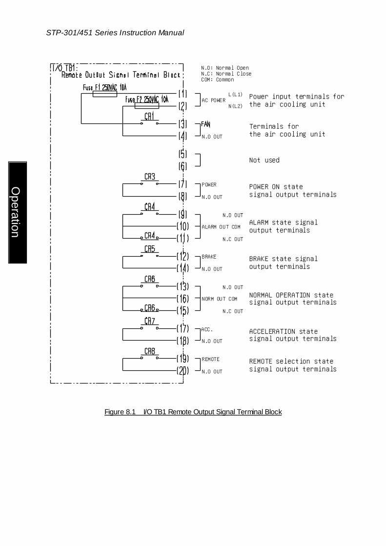
STP-301/451 Series Instruction Manual
Operation
Power input terminals forthe air cooling unit
Terminals forthe air cooling unit
Not used
POWER ON statesignal output terminals
L(L1)AC POWER
N(L2)
N.O OUT
POWER
N.O OUT
N.O OUT
ALARM OUT COM
N.C OUT
BRAKE
N.O OUT
N.O OUT
NORM OUT COM
N.C OUT
ACC.
N.O OUT
REMOTE
N.O OUT
ALARM state signaloutput terminals
BRAKE state signaloutput terminals
NORMAL OPERATION statesignal output terminals
ACCELERATION statesignal output terminals
REMOTE selection statesignal output terminals
N.O: Normal OpenN.C: Normal CloseCOM: Common
Figure 8.1 I/O TB1 Remote Output Signal Terminal Block

STP-301/451 Series Instruction Manual
Ope
ratio
n
Table 8.2 shows rated contacts for relays CR1, 3, 5, 7, and 8 (see Figure 8.1).
Table 8.2 Rated Contacts for Relays CR1, 3, 5, 7, and 8
Resistance Load
(cos φ=1)
Induction Load (cos φ=0.4) (L/R=7 ms)
Rated Load 250 V AC 10 A 30 V DC 10 A
250 V AC 5A 30 V DC 5A
Rated Current 10 A Maximum Contact Point
Voltage 380 V AC 125 V DC
Maximum Contact Point Current
10 A
Maximum Open/Close Capacity
AC: 2500 VA DC: 300 W
AC: 1250 VA DC: 220 W
Minimum Applicable Load
5 V DC, 10 mA
Table 8.3 shows rated contacts for relays CR4 and 6 (see Figure 8.1).
Table 8.3 Rated Contacts for Relays CR4 and 6
Resistance Load
(cos φ=1)
Induction Load (cos φ=0.4) (L/R=7 ms)
Rated Load 250 V AC 8 A 30 V DC 8 A
250 V AC 6 A 30 V DC 4 A
Rated Current 8 A Maximum Contact Point
Voltage 380 V AC 125 V DC
Maximum Contact Point Current
8 A
Maximum Open/Close Capacity
AC: 2000 VA DC: 240 W
AC: 1500 VA DC: 120 W
Minimum Applicable Load
5 V DC, 100 mA

STP-301/451 Series Instruction Manual
Operation
8.2 I/O TB2 Terminal Block
This is a terminal block for remote input signals. Use it in accordance with Table 8.4 and Figure 8.2. (See Section 7.5, "Remote Operation (I/O TB2).") This terminal block operates only during the REMOTE operations. Switch "OFF" the No.4 switch of the DSW-B with CON 4. The screw for the terminal is M4*1. Three abbreviations are used in the following table:
COM: Common IN: Input Terminal OUT: Output Terminal Table 8.4 I/O TB2 Terminal Block
Terminal Description Terminals for outputting the power (12 V DC) for driving remote signals.
(2) (1)
OV
OUT
+12V
OUT
◇ NEVER use these terminals for the purpose except REMOTE operations. DO NOT connect these terminals to another pow er line. Doing so causes a failure.
COMMON IN
(5) (3)
START IN
Terminals for inputting the START signal. The following three methods are available: 1) Short the circuits between (2)-(3) and (1)-(4). Then,
shorting the circuit between (4)-(5) for 0.3 seconds or more causes the STP pump to start. When this signal is input simultaneously with switching ON the breaker on the rear panel, short the circuit for 5 seconds or more.
2) Short the circuit between (2)-(3). Then, shorting the circuit between (1)-(5) causes the STP pump to start.
3) Input 25 V AC or 12 to 48 V DC between (3)-(5) to start the STP pump. With DC input, the (+) side can be connected to either (3) or (5).
COMMON IN
(4) (3)
STOP IN
Terminals for inputting the STOP signal. This STOP signal has priority over the START signal. 1) When 1) above is used to start the STP pump, open the
circuit between (1)-(4) to stop the pump. 2) When 2) above is used, open the circuit between
(1)-(5) to stop the pump. 3) When 3) above is used, open the circuit between
(3)-(5) to stop the pump.
*1 JIS

STP-301/451 Series Instruction Manual
Ope
ratio
n
COMMON IN
(6) (3)
RESET IN
Terminals for inputting the abnormality RESET signal. 1) When 1) or 2) above is used, shorting the circuit between
(1)-(6) for 0.3 seconds or more turns off the "FAILURE" lamp.
2) When 3) above is used, input 25 V AC or 12 to 48 V DC between (3)-(6) for 0.3 seconds or more to turn off the "FAILURE" lamp. With DC input, the (+) side can be connected to either (3) or (6).
◇ When performing all of the START, STOP, and RESET operations using method 3
show n in the above table,25 to 250 V AC can be input. In this case, attach a metallic cover or a similar part to the terminal block to ensure the safety.

STP-301/451 Series Instruction Manual
Operation
I/O TB2:Remote Input Signal Terminal Block
Rated CurrentApprox. 1mA
Fuse
Approx. 330 ohms
Approx. 10 ohms
F3 AC250V 0.1A
+12V +12V
0V
COM
STOP
START
RESET
In case of 3)in Table 8.4
In case of 2) in Table 8.4
In case of 1) in Table 8.4
25VAC12 to 48VDC
F1 250VAC 0.1A
F4 AC250V 0.1A
F2 AC250V 0.1A
Approx. 1mA
Approx. 1mA
◇ I/O TB2 fuses F1 to 4 are on the substrate in the circuit.
For their replacement, contact service office. ◇ The input current of remote input signal is approx. 1mA. Make sure the minimum
applicable load of the relay contact w hen the remote operation w ith the relay.
Figure 8.2 I/O TB2 Remote Input Signal Terminal Block

STP-301/451 Series Instruction Manual
Ope
ratio
n
8.3 CON4 Connector (Optional accessory)
This is a connector for remote input/output signals. This connector can maintain compatibility with the remote I/O signal of the STP-200/300/400 series. The remote input signal from the CON 4 connector is valid by setting No.4 switch of the DSW-B on the top panel to "ON". In this case, remote input from I/O TB2 terminal is invalid. (Refer to Figure 6.3, " STP Control Unit Top Panel" for the position of "DSW-B.") This connector is GP-IB*1 type (24pin) 8.3.1 Remote Input Signals
Use input signals according to Table 8.5 and Figure 8.3. See Section 7.6, “Remote Operation (CON4)”. This input signal is valid only when No.4 of the DSW-B is "ON" in the remote operation.
Table 8.5 CON4 Connector (Remote Input Signal)
Pin Description (2) (14)
RESET IN
+ -
Pins for inputting the RESET signal. When inputting 24VDC between (2)-(14) for 0.3 seconds or more, the "FAILURE" lamp is turned off. Connect the (+) side to (2), and the (-) side to (14). (It is an equivalent to the pin for inputting the "POWER OFF" signal of the STP-200/300/400 series.)
(3) (15)
START IN
+ -
Pins for inputting the START signal. When inputting 24VDC between (3)-(15) for 0.3 seconds or more, the pump starts operation. However, when inputting the signal simultaneously with switching "ON" the breaker on the rear panel, continue to short the circuit for 5 seconds or more. Connect the (+) side to (3), and the (-) side to (15).
(4) (16)
STOP IN
+ -
Pins for inputting the STOP signal. This STOP signal has priority over he START signal. When inputting 24VDC between (4)-(16) for 0.3 seconds or more, the pump stops operation. Connect the (+) side to (4), and the (-) side to (16).
(1) (13)
Not used. (It corresponds to the pin for inputting the "POWER ON" signal of the STP-200/300/400 series.)
*1: General Purpose - Interface Bus (Conforms to IEEE-STD-488-1978)
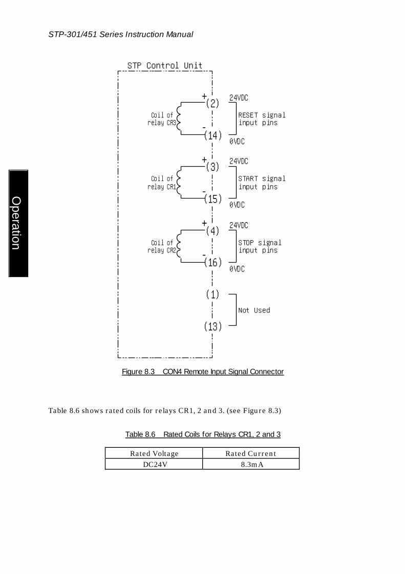
STP-301/451 Series Instruction Manual
Operation
(2)+
(14)-
Coil ofrelay CR3
RESET signal input pins
(3)+
(15)-
(4)+
(16)-
(1)
(13)
STP Control Unit
24VDC
0VDC
24VDC
0VDC
24VDC
0VDC
Coil ofrelay CR1
Coil ofrelay CR2
START signal input pins
STOP signal input pins
Not Used
Figure 8.3 CON4 Remote Input Signal Connector
Table 8.6 shows rated coils for relays CR1, 2 and 3. (see Figure 8.3)
Table 8.6 Rated Coils for Relays CR1, 2 and 3
Rated Voltage Rated Current DC24V 8.3mA

STP-301/451 Series Instruction Manual
Ope
ratio
n
8.3.2 Remote Output Signals
Use output signals according to Table 8.7 and Figure 8.4. This output signal operates in both manual operation and remote operation. No.4 of the DSW-B DIP switch operates in "ON/OFF" both states.
Table 8.7 CON 4 Connector (Remote output signal)
Pin Description (5) (17)
REMOTE
N.O OUT
Pins for outputting the STP pump REMOTE SELECTION state signal. When the MANUAL/REMOTE changeover switch on the STP front panel is set to ON (remote side), these pins are closed (REMOTE operation). However, during power failure backup operation, this signal is not output.
(6) (18) ROTATION
N.O OUT
Pin for outputting the rotational state signal. These pins are closed when the STP pump is in rotation. However, during power failure backup operation, this signal is not output. (It corresponds to the pin for outputting the "POWER ON" signal of the STP-200/300/400 series.)
(7) (19) EMERGENCY OPERATION
N.O OUT
Pins for outputting the EMERGENCY OPERATION state signal. These pins are closed when failures are detected as follows. Abnormal state of magnetic bearing Excessive Vibration
However, during power failure backup operation, this signal is not output.
(8) (20) FAILURE
N.O OUT
Pins for outputting the FAILURE state signal. These pins are closed when failures are detected as follows. Motor driver overload Overheating inside the STP pump Overheating inside the STP control unit Overspeed
However, during power failure backup operation, this signal is not output.
(9) (21) OVER
TEMPERATUR
N.O OUT
Pins for outputting the OVER TEMPERATURE state signal. These pins are closed when overheating inside the STP pump is detected. However, during power failure backup operation, this signal is not output.
(11) (23) ACCELERATION
N.O OUT
Pins for outputting the ACCELERATION state signal. These pins are closed when the STP pump is in acceleration.

STP-301/451 Series Instruction Manual
Operation
(11) (24) NORMAL
OPERATION
N.O OUT
Pins for outputting the NORMAL OPERATION state signal. These pins are closed when the STP pump is in rated operation.
(10) (22) Not used. (It corresponds to the pin for outputting the "BATTERY OPERATION " signal of the STP-200/300/400 series.)
(12) Not used. It is connected to the frame ground.

STP-301/451 Series Instruction Manual
Ope
ratio
n
(5)
(17)
Remote selection statesignal output pins
(6)
(18)Rotational statesignal output pins
(7)
(19)EMERGENCY OPERATION statesignal output pins
(8)
(20)
FAILURE statesignal output pins
CR10
(9)
(21)OVER TEMPERATURE statesignal output pins
CR9
(11)
(23)ACCELERATION statesignal output pins
CR8
(24)NORMAL OPERATION statesignal output pins
CR7
(10)
(22)Not used
(12) Frame groundFG
STP Control Unit
CR4
CR5
CR6
Figure 8.4 CON4 Remote Output Signal Connector

STP-301/451 Series Instruction Manual
Operation
Table 8.8 shows rated contacts for relays CR4, 5, 6, 7, 8, 9 and 10. (see Figure 8.4)
Table 8.8 Rated Contacts for Relays CR4, 5, 6, 7, 8, 9 and 10
Resistance Load (cos φ=1)
Induction Load (cos φ=0.4) (L/R=7 ms)
125VAC 0.4A 125VAC 0.2A Rated Load 30VDC 2A 30VDC 1A
Rated Current 3A Maximum Contact
Point Voltage 250VAC 220VDC
Maximum Contact Point Current
3A
Maximum Open/Close Capacity
AC: 50VA DC: 60W
AC: 25VA DC: 30W
Minimum Applicable Load
DC10mV 10μA
8.3.3 Remote Cables (Optional Accessories)
Remote cables for CON4 are provided as optional accessories. Remote cables are available in two types: single-side connector type and both-side connector type. Contact BOC Edwards for details. Table 8.9 shows connections of remote cables of single-side connector type.
Table 8.9 Remote Cable Connections (Single-Side Connector Type)
ConnectorPin No.
Cable Color Connector Pin No.
Cable Color
1 Brown 13 White/Orange 2 Red 14 White/Yellow 3 Orange 15 White/Green 4 Yellow 16 White/Blue 5 Blue 17 Green 6 Purple 18 White/Black/Brown 7 Gray 19 White/Black/Red 8 White 20 White/Black/Orange 9 White/Black 21 White/Black/Yellow 10 White/Brown 22 White/Black/Green 11 White/Red 23 White/Black/Blue
12, hood Shielded 24 White/Purple, White/Gray

9 Adjustment Method 9.1 Tuning
For the STP pump, tuning is required to align the position of levitation in the axial direction with the center of the rotor's movable range. The tuning can be performed simply by pressing the "RESET" switch.
The tuning is completed before delivery, so it is not required before use. However, re-tuning is required in the following cases in which the position of levitation may deviate from the center of the rotor's movable range:
◇ When changing the length of the STP connection cable (not w hen changing the length of the pow er cable)
◇ When using the STP pump and STP control unit having different serial numbers 9.1.1 Tuning Method
1) Connect each cable. 2) Switch "ON" the breaker on the rear panel. 3) After the STP pump completes the self test and enter the levitation state, press the
"RESET" switch on the front panel for approx. 3 seconds. The tuning starts with "TUNING!" displayed in the LCD.
4) When the LCD displays "TUNING!", release the "RESET" switch. 5) Approx. one minute later the LCD displays "TUNING COMPLETE" and returns to
the message displayed in 3). This completes the tuning.
◇ The tuning can be performed only w hen the STP pump is in the LEVITATION state.
(It cannot be performed w hen the STP pump is in the ACCELERATION, NORMAL OPERATION, or BRAKE state.) Also, the tuning can be performed w hen any message of "LEVITATION", "RATING: ***00rpm", or "PUMP TEMP: **°C" is displayed.
◇ When performing the tuning during remote operation, also use the "RESET" sw itch on the front panel. (The remote signal cannot be used for tuning.)
◇ Once the tuning is completed, re-tuning is not required unless the configuration (the STP pump serial number, the STP control unit serial number, and the STP connection cable length) is changed.
◇ Although the STP pump sounds during tuning, this is not an indication of abnormality.
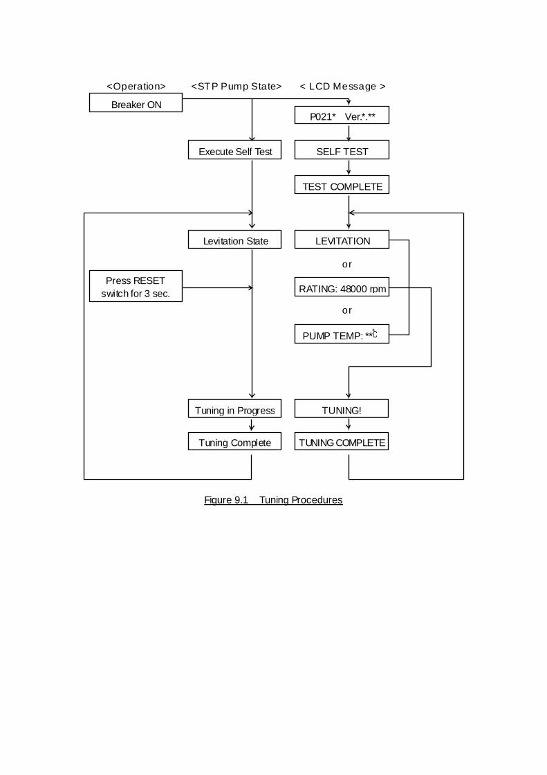
TUNING COMPLETE
RATING: 48000 rpm
LEVITATION
TUNING!
Tuning Complete
Tuning in Progress
PUMP TEMP: **℃
Press RESETswitch for 3 sec.
< LCD Message ><STP Pump State><Operation>
Levitation State
TEST COMPLETE
SELF TESTExecute Self Test
P021* Ver.*.**Breaker ON
or
or
Figure 9.1 Tuning Procedures

9.2 Setting the Rated Speed
The STP pump can be set (changed) to the required rated speed in the range of 25,000 to 48,000 rpm, in units of 500 rpm. The setting can be performed even during rotation of the STP pump. The rated speed is set to 48,000 rpm at delivery. The rated speed setting mode is entered by setting dip switch 1 of DSW-B on the top panel to the ON position. The rated speed is set to 48,000 rpm (initial setting) by setting dip switch 1 to the OFF position. For the position of the DSW-B switch, see Figure 6.3, "STP Control Unit Top Panel." Prepare the following tool for setting the rated speed:
Small-sized screwdriver 9.2.1 When Setting DSW-B No. 1 to ON under Pow er-ON State
1) Set dip switch 1 of DSW-B to the ON position. The LCD displays "SET= ***00rpm," which indicates the rated speed setting mode. The speed displayed here depends on the current position dialed with the VR1 volume on the top panel.
2) Turning the VR1 volume on the top panel changes the value "***00rpm" on the rated speed setting display "SET= ***00rpm." Turn the VR1 volume clockwise to increase the rated speed, or counterclockwise to decrease the rated speed, until the required rated speed is displayed. Note that the rated speed is not yet determined in this state.
3) To determine the rated speed displayed in "SET= ***00rpm," press the "START" switch. When the STP pump is in the ACCELERATION or NORMAL OPERATION state, it accelerates or decelerates up to the set value of rated speed. When the STP pump is in the LEVITATION or BRAKE state, the pump's state remains unchanged. Note that the rated speed is not determined if the "START" sw itch is pressed w hen the LCD message is other than "SET= ***00rpm."
4) Press the "SELECT" switch once, and the LCD displays the set value of rated speed in "RATING: ***00rpm." Make sure the required rated speed is displayed. If the required speed is not displayed or the rated speed is to be changed again, press the "SELECT" switch to display "SET= ***00rpm" again. Then, perform steps 2) and 3) again to set the rated speed.
5) When the STP pump is in the LEVITATION or BRAKE state, perform STP pump rotation operation to rotate it. The STP pump accelerates up to the rated speed.

9.2.2 When Setting DSW-B No. 1 to ON before Pow ering On
1) Set dip switch 1 of DSW-B to the ON position. 2) Switch "ON" the breaker on the rear panel.
After the STP pump completes the self test, the LCD displays the current rated speed in "RATING: ***00rpm." The rated speed displayed here is the previously set rated speed (or initial rated speed 48,000 rpm).
3) Press the "SELECT" switch three times to display "SET= ***00rpm," which indicates the rated speed setting mode.
4) Turning the VR1 volume on the top panel changes the value "***00rpm" on the rated speed setting display "SET= ***00rpm." Turn the VR1 volume clockwise to increase the rated speed, or counterclockwise to decrease the rated speed, until the required rated speed is displayed. Note that the rated speed is not yet determined in this state.
5) To determine the rated speed displayed in "SET= ***00rpm," press the "START" switch. Note that the rated speed is not determined if the "START" sw itch is pressed w hen the LCD message is other than "SET= ***00rpm."
6) Press the "SELECT" switch once, and the LCD displays the set value of rated speed in "RATING: ***00rpm." Make sure the required rated speed is displayed. If the required rated speed is not displayed or the rated speed is to be changed again, press the "SELECT" switch to display "SET= ***00rpm" again. Then, perform steps 4) and 5) again to set the rated speed.
7) Perform STP pump rotation operation to start the STP pump. The STP pump accelerates up to the rated speed.
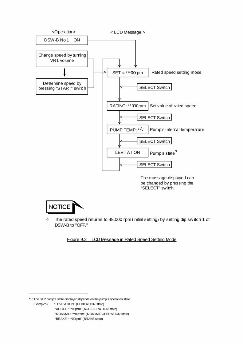
PUMP TEMP: **℃
RATING: **000rpm
LEVITATION
Change speed by turning VR1 volume
The massage displayed can be changed by pressing the “SELECT” switch.
Determine speed by pressing “START” switch
< LCD Message > <Operation>
SELECT Switch
SELECT Switch
SELECT Switch
Pump’s state*1
Pump’s internal temperature
Set value of rated speed
Rated speed setting mode
SELECT Switch
SET = ***00rpm
DSW-B No.1 ON
◇ The rated speed returns to 48,000 rpm (initial setting) by setting dip sw itch 1 of
DSW-B to "OFF."
Figure 9.2 LCD Message in Rated Speed Setting Mode
*1: The STP pump’s state displayed depends on the pump’s operation state.
Examples) “LEVITATION” (LEVITATION state) “ACCEL: ***00prm” (ACCELERATION state) “NORMAL: ***00rpm” (NORMAL OPERATION state) “BRAKE: ***00rpm” (BRAKE state)
STP-301/451 Series Instruction Manual
10-1
Trou
bles
hoot
ing
10 Safety Functions 10.1 Pow er Failure
<Operation at a Power Failure> When the power voltage drops below 170 V (in case of 200 V specification) or below 85 V (in case of 100 V specification) due to power failure, the normal operation of the magnetic bearing is maintained using the regenerative energy of the rotating rotor (backup operation during a power failure). 1) When the rotational speed is 25,000 rpm or more at a power failure:
I. The STP control unit detects any power failure of 2 seconds or more and the
STP pump decelerates. At this time, the "POWER" lamp goes out and the "FAILURE" lamp lights. The LCD displays "POWER FAILURE." Also, an alarm signal is output from I/O TB1 ALARM OUT terminals (10)-(9) and (10)-(11). When the number of rotations goes down to 20,000 rpm, the backlight of the LCD goes out and the alarm signal output is reset. When the number of rotations goes down to approx. 17,000 rpm, the rotor lands on the touch down bearing and stops. The "FAILURE" lamp goes out and the LCD is turned off.
II. The STP control unit does not detect a power failure of less than 2 seconds, continuing rotating the STP pump.
2) When the rotational speed is 17,000 rpm or more and less than 25,000 rpm at a
power failure: The STP control unit detects a power failure of approx. 0.02 to 0.14 seconds and the STP pump decelerates.
At this time, the "POWER" lamp goes out and the "FAILURE" lamp lights. The LCD displays "POWER FAILURE". Also, an alarm signal is output from I/O TB1 ALARM OUT terminals (10)-(9) and(10)-(11). However, when the number of rotations is less than 20,000 rpm at the occurrence of a power failure, no alarm signal is output. When the number of rotations goes down to 20,000 rpm, the backlight of the LCD goes out and the alarm signal output is reset. When the number of rotations goes down to approx. 17,000 rpm, the rotor lands on the touch down bearing and stops. The "FAILURE" lamp goes out and the LCD is turned off.
◇ A pow er failure is detected faster the less the rotational speed at the pow er
failure. 3) When the rotational speed is less than approx. 17,000 rpm at a power failure:
The STP control unit does not detect the power failure; the rotor lands on the touch down bearing and stops.

STP-301/451 Series Instruction Manual
10-2
Troubleshooting
< Operation after a Power Recovery> 1) MANUAL operation
The STP pump continues decelerating even after a power recovery. Press the "START" switch to reaccelerate the STP pump.
2) REMOTE operation
When the START signal is input to the REMOTE input terminal at a power recovery to reaccelerate the STP pump.
When the START signal is not input to the REMOTE input terminal after a power recovery, the STP pump continues the BRAKE operation.
◇ Establish a sequence so that the pow er can be supplied to the STP control unit
immediately after a pow er recovery. Table 10.1 shows the states of lamps and the REMOTE output signals at a power failure. Also, Table 10.2 shows the operations of the STP pump after a power recovery.
Table 10.1 States of Lamps and REMOTE Output Signals at Pow er Failure
LCD LED lamps REMOTE output signals (I/O TB1) Rotational speed
(rpm) Message Backlight POWER
lamp FAILURE
lamp Power ON
signal ALARM signal
20,000 or more POWER FAILURE
ON OFF ON OFF ON
17,000 or more and less than 20,000
POWER FAILURE
OFF OFF ON OFF OFF
Less than 17,000 OFF OFF OFF OFF OFF OFF
Table 10.2 Operations of the STP Pump after Pow er Recovery
MANUAL operation REMOTE operation
Rotational speed (rpm)
Duration of power failure
STP pump operation after power recovery
"START" REMOTE signal input after power recovery
STP pump operation after power recovery
Yes Reacceleration Approx 2 sec or longer
Deceleration/Stop No Deceleration/Stop 25,000 or more
Shorter than approx 2 sec
Continues as before.
Yes Reacceleration Approx 0.02 to 0.14 sec*1
Deceleration/Stop No Deceleration/Stop Less than 25,000
Shorter than the above
Continues as before.
*1: A power failure is detected faster the less the number of rotations at the power failure.

STP-301/451 Series Instruction Manual
10-3
Trou
bles
hoot
ing
10.2 Abnormal State of Magnetic Bearing
When the magnetic bearing does not function normally due to a breakage of the STP connection cable, disconnection of connectors or any abnormality/error of the STP control circuit, the rotor falls on the touch down bearing and stops. Simultaneously, the "FAILURE" lamp lights and the LCD displays error message "DISTURBANCE."
◇ When an abnormality/error occurs in the magnetic bearing, check the STP pump
as w ell as the STP control unit, and contact service off ice. 10.3 Excessive Vibration
When serious vibration or mechanical shock causes the rotor to touch the touch down bearing (due to external vibration/impact, intrusion of atmosphere or foreign particles into the STP pump or rotor imbalance), the STP pump decelerates and stops. Simultaneously, the “FAILURE” lamp lights and the LCD displays error message "DISTURBANCE." 10.4 Motor Driver Overload
When the STP pump does not attain the rated speed within approx. 10 minutes after starting or when the ACCELERATION state remains unchanged during operation for approx. 10 minutes, the STP pump decelerates and stops. Simultaneously, the "FAILURE" lamp lights and the LCD displays error message "OVERLOAD." 10.5 Overheating Inside the STP Pump
When the temperature of the motor inside the STP pump exceeds 110°C due to an abnormal baking temperature or overload operation, the STP pump decelerates and stops. Simultaneously, the "FAILURE" lamp lights and the LCD displays error message "PUMP OVERTEMP." 10.6 Overheating Inside the STP Control Unit
When the temperature inside the STP control unit exceeds 70°C due to a failure in the air cooling fan, external heat source, and other, the STP pump decelerates and stops. Simultaneously, the "FAILURE" lamp lights and the LCD displays error message "CONTROLLER OT." 10.7 Overspeed
STP-301/451 Series Instruction Manual
10-4
Troubleshooting
When the rotational speed of the STP pump exceeds 51,400 rpm due to a failure in the motor driver, the breaker in the STP control unit switches "OFF." The STP pump has no power supplied and stops. Simultaneously, the "FAILURE" lamp lights and the LCD displays error message "OVERSPEED" or "DRIVERRA".

STP-301/451 Series Instruction Manual
10-5
Table 10.3 Safety Functions
Abnormality /Error
Operation state of safety functions
Lamp indication LCD
REMOTE output signal State of the STP pump
Probable causes of an abnormality/error
Reset by RESET
operation Power failure Power failure
time: 2 seconds or longer.
"FAILURE" lights.
"POWER" goes out.
"POWER FAILURE"
"ALARM"
"POWER ON" output cut-off
The magnetic bearing continues to operate using regenerative energy. The STP pump decelerates and stops. The rotor lands on the touch down bearing at approx. 17,000 rpm.
Power failure. Power cable breakage. Power cable disconnection.
Impossible
Abnormal magnetic bearing
Rotor descends onto the touch down bearing.
"FAILURE" "DISTURBANCE" "ALARM" The rotor stops on the touch down bearing.
STP connection cable breakage. STP connection cable disconnection. Abnormal control circuit.
Possible
Excessive vibration
Rotor vibration:100 µm 0-P or more.
"FAILURE" "DISTURBANCE" "ALARM" The STP pump decelerates and stops.
External vibration, and impact. Intrusion of atmospheric air. Intrusion of foreign particles.
Possible

STP-301/451 Series Instruction Manual
10-6
Abnormality /Error
Operation state of safety functions
Lamp indication LCD
REMOTE output signal State of the STP pump
Probable causes of an abnormality/error
Reset by RESET
operation Overload of motor driver
Excessive current flows in the motor.
"FAILURE" "OVERLOAD" "ALARM" The STP pump decelerates and stops.
Leakage from the vacuum equipment or piping. Insufficient pressure at inlet and outlet port sides. Failure of starting of the backing pump.
Possible
Overheating inside the STP pump
Temperature ofthe STP pump motor: 110℃ or more.
"FAILURE" "PUMP OVERTEMP"
"ALARM" The STP pump decelerates and stops.
Abnormal baking temperature. Insufficient cooling. Leakage of vacuum equipment or piping. Continuous repetition of startup/stop. Extraordinarily-high temperature.
Possible
Overheating inside the STP control unit
70℃ or more inside the STP control unit.
"FAILURE" "CONTROLLER OT"
"ALARM" The STP pump decelerates and stops.
Failure in the cooling fan. Shielding of cooling air inlet and ventilation port. Extraordinarily-high temperature.
Possible
Overspeed Rotational speed of the STP pump: 51,400 rpm or more.
"FAILURE" "OVERSPEED" or
"DRIVER RA"
"ALARM" Breaker OFF. Power failure state. The STP pump stops.
Failure in the motor driver.
Impossible

11 Troubleshooting, Maintenance and Inspection The STP pump is provided with safety functions for various abnormalities/errors. When an abnormality occurs in the STP pump or STP control unit, a safety function operates with the "FAILURE" lamp lit, and an alarm signal is output from remote output terminals. Also, the LCD displays an error message. If an abnormality/error is found when using the STP pump, check it and take measures in accordance with the following procedures. If you cannot trace it or if the STP pump does not function normally after the troubleshooting, fill in the necessary information in the "Malfunction Information" and fax it to Service office.
◇ After confirming that the STP pump stops thoroughly, turn OFF the primary
pow er (sw itch the breaker "OFF"), check probable causes and remove them. 11.1 Troubleshooting Immediately After An Abnormality/Error Occurs
11.1.1 In Case of a Pow er Failure:
Establish a sequence so that the power can be supplied to the STP control unit immediately after a power recovery. 11.1.2 In Other Cases
1) After confirming the "BRAKE" lamp goes out and the STP pump stops, remove the probable cause of the abnormality.
2) Perform the RESET operation according to turn off the "FAILURE" lamp. 3) Perform the START operation. Check if the STP pump operates correctly.
◇ When disconnecting cables from the STP pump and/or the STP control unit to
perform troubleshooting and take the necessary action, confirm that the STP pump stops, sw itch OFF the primary pow er (breaker "OFF"), then disconnect the cables.
◇ If the RESET operation does not turn off the "FAILURE" lamp, confirm that the STP pump stops, sw itch OFF the primary pow er (breaker "OFF"), then sw itch "ON" the primary pow er again (breaker "ON").
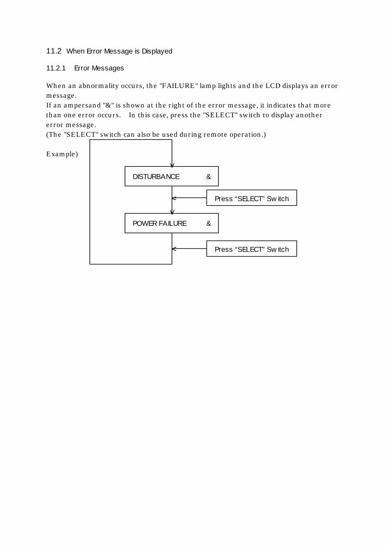
11.2 When Error Message is Displayed
11.2.1 Error Messages
When an abnormality occurs, the "FAILURE" lamp lights and the LCD displays an error message. If an ampersand "&" is shown at the right of the error message, it indicates that more than one error occurs. In this case, press the "SELECT" switch to display another error message. (The "SELECT" switch can also be used during remote operation.) Example)
DISTURBANCE &
POWER FAILURE &
Press “SELECT” Sw itch
Press “SELECT” Sw itch

Table 11.1 Error Messages
LCD Message Probable Cause Countermeasures Refer to Incorrect connection of the STP connection cable
Connect the cable correctly. If the cable connector is not locked, lock it securely.
6.4.2 CABLE DISCONNECT
Failure of the STP connection cable
Contact Service office. Malfunction Information
Overheating inside the STP control unit
1) Ambient temperature 1) Set the ambient temperature to 40°C or less.
6.2.1
CONTROLLER OT
2) Insufficient cooling of the STP control unit
2) Remove obstacles from the ventilation port. If the air cooling fan is broken, contact Service office.
6.2.3 11.3.1
Abnormal magnetic bearing 1) The STP pump and the
STP control unit have different serial numbers.
1) Use the units having the same serial number, or perform tuning.
9.1
2) The cable length is changed.
2) Perform tuning. 9.1
Excessive external vibration (vibration of 100μm0-P or more)
1) External vibration/impact 1) Remove the external vibration so as not to transmit it to the STP pump.
4.3.4
2) Atmospheric air flows into the STP pump
2) Check piping. 4.3.4
DISTURBANCE
3) Foreign particles fall into the STP pump
3) Install the pump in a way that no foreign particles fall into the pump.
4.3.1
DRIVER ERROR 1 DRIVER ERROR 2 DRIVER ERROR 3 DRIVER ERROR 4 DRIVER ERROR
Motor driver failure Contact Service office.
Malfunction Information

LCD Message Probable Cause Countermeasures Refer to 5 DRIVER ERROR 6 DRIVER HF Hall sensor error Contact Service office. DRIVER OC Motor driver overcurrent Contact Service office. DRIVER OV Motor driver overvoltage Contact Service office. DRIVER RA STP pump overspeed
(detected in the range of 49,500 to 53,000 rpm)
Contact Service office.
DRIVER UV Motor driver undervoltage Contact Service office.
Malfunction Information
Motor driver overload 1) Insufficient pressure at
the inlet port 1) Use the maximum
working pressure or less.
4.3.4 13.1
2) Insufficient pressure at the outlet port
2) Use the allowable backing pressure or less.
4.3.4 13.1
3) Leakage of the piping system
3) Check the piping system.
4.3.4
OVERLOAD
4) Failure of the backing pump
4) Check the backing pump for its capacity and start state. (use a pump with the recommended capacity or more)
4.3.4 13.1
OVERSPEED STP pump overspeed (detected at over 51,400 rpm)
Contact Service office. Malfunction Information
Power supply failure 1) Power failure 1) Check whether or not a
power failure has occurred.
10.1
2) Incorrect connection of power cable
2) Connect the power cable correctly.
6.4.2
3) Power cable breaking 3) Replace the power cable. 6.4.2
POWER FAILURE
4) Abnormal power voltage 4) Set the voltage to 100 to 120V +/-10% (100V spec.) or to 200 to 240V +/-10% (200V spec.).
6.4.2
Overheating inside the STP pump
PUMP OVERTEMP
1) Overheating during baking
1) et the temperature of baking heater to 120°C or lower.
5.1
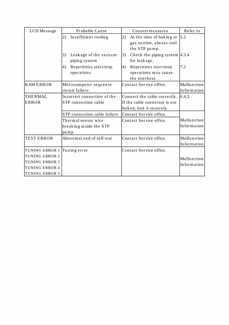
LCD Message Probable Cause Countermeasures Refer to 2) Insufficient cooling 2) At the time of baking or
gas suction, always cool the STP pump.
5.2
3) Leakage of the vacuum piping system
3) Check the piping system for leakage.
4.3.4
4) Repetitious start/stop operations
4) Repetitious start/stop operations may cause the overheat.
7.2
RAM ERROR Microcomputer sequence circuit failure
Contact Service office. Malfunction Information
Incorrect connection of the STP connection cable
Connect the cable correctly. If the cable connector is not locked, lock it securely.
6.4.2
STP connection cable failure Contact Service office.
THERMAL ERROR
Thermal sensor wire breaking inside the STP pump
Contact Service office. Malfunction Information
TEST ERROR Abnormal end of self test Contact Service office. Malfunction Information
TUNING ERROR 1 TUNING ERROR 2 TUNING ERROR 3 TUNING ERROR 4 TUNING ERROR 5
Tuning error Contact Service office.
Malfunction Information

11.2.2 Displaying Past Abnormalities/Errors and Accumulated Running-Time
(This function is available with the STP pump of "Ver. 2.20" and after. How to check the version is shown on the next page.)
The STP pump provides a function that the LCD displays a maximum of eight error messages that occurred in the past, and a total of running-time in hours (acceleration, rated speed operation, and deceleration). <How to display error messages> 1) Press and hold the "SELECT" switch for approx. 3 seconds or more when the LCD
displays a pump's state message. The LCD displays the accumulated running time and then error messages that occurred in the past (error record display mode). The number displayed at the right of the error message is an error sequence number. The smaller number indicates that the error occurred more recently.
2) To return to the previous pump's state message, press and hold the "SELECT" switch again for approx. 3 seconds or more, or leave the error message displayed for approx. 20 seconds without pressing the "SELECT" switch.
< LCD Message >
POWER FAILURE 1
RUN : 1,500 hrs
LEVITATION
LEVITATION
PUMP OVERTEMP 2
Press SELECT switch for approx. 3 sec. or leave the message displayed for approx. 20 sec.
Pump’s state display mode
Error record display
Pump’s state display mode
Operating time display
SELECT Switch
SELECT Switch
Press SELECT switch for about 3 sec.
POWER FAILURE 1
RUN : 1,500 hrs
PUMP OVERTEMP 8
SELECT Switch
SELECT Switch
Changing display in error record display mode
Switching display between state message and error record message
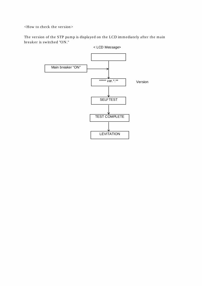
<How to check the version> The version of the STP pump is displayed on the LCD immediately after the main breaker is switched "ON."
< LCD Message>
Main breaker “ON”
SELFTEST
***** ver.*.**
LEVITATION
TEST COMPLETE
Version

11.2.3 Abnormalities When Pow ering ON
Table 11.2 Troubleshooting after Pow ering ON
Symptom Probable cause Countermeasures Refer to The "POWER" lamp does not light, when powering ON.
Incorrect connection of the power cable
Connect the power cable correctly.
6.4.2
Abnormal power voltage Set the voltage to 100 to 120V +/-10% (100V spec.)or 200 to 240V +/-10% (200V spec.).
6.4.2 13.2
Power failure Check whether or not a power failure has occurred.
10.1
The breaker goes OFF when powering ON.
Abnormal power voltage (200V is applied to the STP control unit of 100V spec.)
Set the voltage to 100 to 120V +/-10%.
6.4.2 13.2
11.2.4 Abnormalities When Performing the STP Pump Start Operation
Table 11.3 Troubleshooting When Performing the STP Pump Start Operation
Symptom Probable causes Countermeasures Refer to The "ACCEL." lamp does not light.
LCD message (MANUAL operation only)
Press the "SELECT" switch one or more times until the LCD displays "LEVITATION" or "BRAKE ***00rpm."
7.4.2
The "MANUAL/REMOTE" changeover switch is not at the correct position.
Slide the "MANUAL/REMOTE" changeover switch to thecorrect position.
6.1.1 7.4 7.5
Blown fuses (F1 to 4) for remote signal input (REMOTE operation only)
Replace the blown fuses. Contact Service office.
8.2 Malfunction Information
Incorrect setting of DSW-B No.4 (only with CON4)
Set the DSW-B No.4 to either "ON/OFF" according to the remote input connector/terminal.
6.1.3 7.5/7.6 8.2/8.3
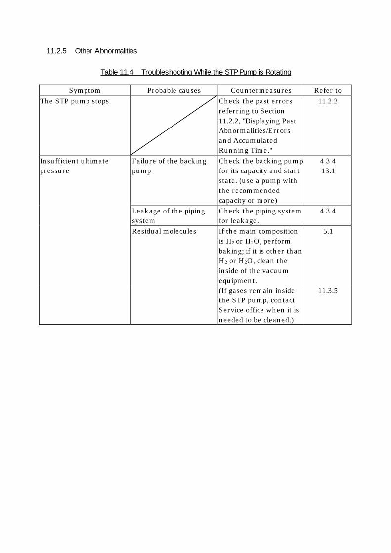
11.2.5 Other Abnormalities
Table 11.4 Troubleshooting While the STP Pump is Rotating
Symptom Probable causes Countermeasures Refer to The STP pump stops. Check the past errors
referring to Section 11.2.2, "Displaying Past Abnormalities/Errors and Accumulated Running Time."
11.2.2
Insufficient ultimate pressure
Failure of the backing pump
Check the backing pump for its capacity and start state. (use a pump with the recommended capacity or more)
4.3.4 13.1
Leakage of the piping system
Check the piping system for leakage.
4.3.4
Residual molecules If the main composition is H2 or H2O, perform baking; if it is other than H2 or H2O, clean the inside of the vacuum equipment.
5.1
(If gases remain inside the STP pump, contact Service office when it is needed to be cleaned.)
11.3.5
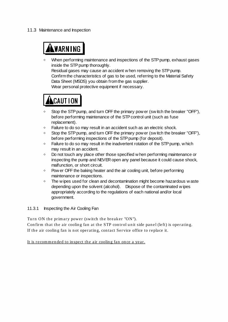
11.3 Maintenance and Inspection
◇ When performing maintenance and inspections of the STP pump, exhaust gases
inside the STP pump thoroughly. Residual gases may cause an accident w hen removing the STP pump. Confirm the characteristics of gas to be used, referring to the Material Safety Data Sheet (MSDS) you obtain from the gas supplier. Wear personal protective equipment if necessary.
◇ Stop the STP pump, and turn OFF the primary pow er (sw itch the breaker "OFF"),
before performing maintenance of the STP control unit (such as fuse replacement).
◇ Failure to do so may result in an accident such as an electric shock. ◇ Stop the STP pump, and turn OFF the primary pow er (sw itch the breaker "OFF"),
before performing inspections of the STP pump (for deposit). ◇ Failure to do so may result in the inadvertent rotation of the STP pump, w hich
may result in an accident. ◇ Do not touch any place other those specified w hen performing maintenance or
inspecting the pump and NEVER open any panel because it could cause shock, malfunction, or short circuit.
◇ Pow er OFF the baking heater and the air cooling unit, before performing maintenance or inspections.
◇ The w ipes used for clean and decontamination might become hazardous w aste depending upon the solvent (alcohol). Dispose of the contaminated w ipes appropriately according to the regulations of each national and/or local government.
11.3.1 Inspecting the Air Cooling Fan
Turn ON the primary power (switch the breaker "ON"). Confirm that the air cooling fan at the STP control unit side panel (left) is operating. If the air cooling fan is not operating, contact Service office to replace it. It is recommended to inspect the air cooling fan once a year.
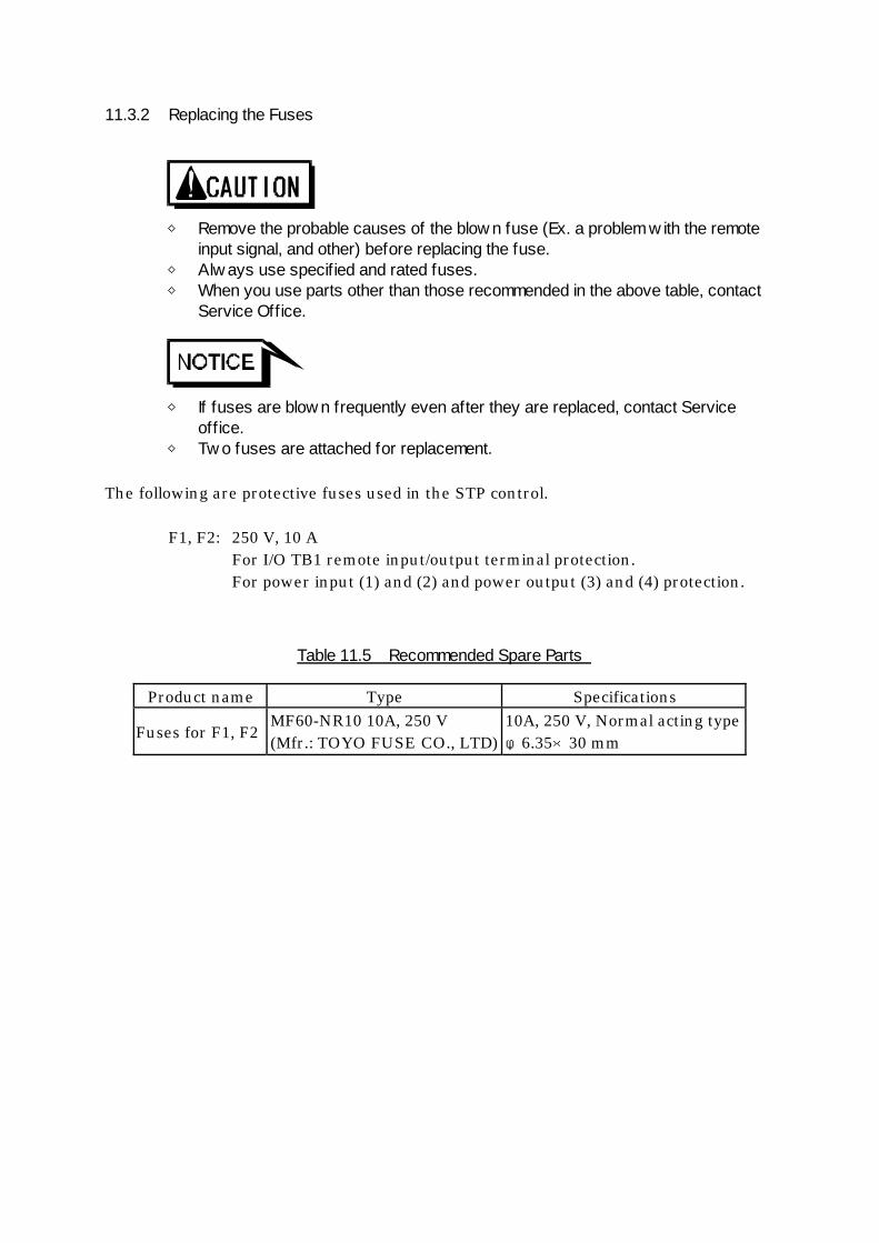
11.3.2 Replacing the Fuses
◇ Remove the probable causes of the blow n fuse (Ex. a problem w ith the remote
input signal, and other) before replacing the fuse. ◇ Alw ays use specified and rated fuses. ◇ When you use parts other than those recommended in the above table, contact
Service Office.
◇ If fuses are blow n frequently even after they are replaced, contact Service
office. ◇ Tw o fuses are attached for replacement.
The following are protective fuses used in the STP control.
F1, F2: 250 V, 10 A For I/O TB1 remote input/output terminal protection. For power input (1) and (2) and power output (3) and (4) protection.
Table 11.5 Recommended Spare Parts
Product name Type Specifications
Fuses for F1, F2 MF60-NR10 10A, 250 V (Mfr.: TOYO FUSE CO., LTD)
10A, 250 V, Normal acting type φ6.35×30 mm

11.3.3 Cleaning and Decontamination
The method of cleaning and decontamination of the STP pump and STP control unit is shown below.
Table 11.6 Cleaning and Decontamination
Area Cleaning and Decontamination Exterior Wipe with proper solvent (such as alcohol).
Clean off with a pure gas when dust has accumulated in the connector. When the label of the STP pump has been damaged, contact Service office.
STP Pump
Interior The decontamination (overhaul) in the STP pump is executed in Service office. When overhaul is needed, contact Service office.
Exterior Wipe with proper solvent (such as alcohol). When dust has accumulated in the ventilation port, wipe off or vacuum it with the cleaner. In this case, dust mustnot enter in the STP control unit. Clean off with a pure gas when dust has accumulated in the connector. When the label of the STP control unit has been damaged,contact Service office.
STP Control unit
Interior The cleaning (overhaul) in the STP control unit is executed in Service office. When overhaul is needed, contact Service office.
11.3.4 Inspecting for Deposit
Leaving the STP pump without removing the deposit may cause the STP pump to be corroded beyond repair. Deposit may have accumulated inside the STP pump depending upon the type of the vacuum equipment installed to the STP pump. An increase in the amount of deposit may lead to a malfunction of the STP pump. Therefore, perform regular maintenance (once every 3 to 6 months). Inspect the inside of the outlet port flange for adhesion of deposit while watching the outlet port flange. If deposit has accumulated to some extent, an overhaul (cleaning) is required. Contact Service office. Note that the costs of troubleshooting problems resulting from deposit will be at your own charge even during the warranty period. If a problem resulting from deposit occurs inside the STP pump, hermetically seal the inlet port, outlet port, purge port, and leak port flanges, and immediately return the pump to Service office. For the transport method, see Section 11.3.6, "Transporting for Repair or Overhaul.”

◇ Contact w ith atmospheric air may cause a reaction of the deposit. DO NOT
open the STP pump to atmospheric air as much as possible.
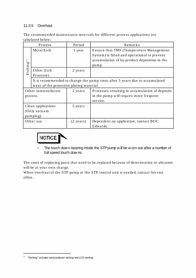
11.3.5 Overhaul
The recommended maintenance intervals for different process applications are tabulated below:
Process Period Remarks Metal Etch 1 year Ensure that TMS (Temperature Management
System) is fitted and operational to prevent accumulation of by-product deposition in the pump.
Other Etch Processes
2 years
Etc
hing
*1
It is recommended to change the pump rotor after 5 years due to accumulated wear of the protective plating material
Other semiconductor process
2 years Processes resulting in accumulation of deposits in the pump will require more frequent service.
Clean applications (Only vacuum pumping)
5 years
Other use (2 years) Dependent on application, contact BOC Edwards.
◇ The touch dow n bearing inside the STP pump w ill be w orn out after a number of
full speed touch dow ns. The costs of replacing parts that need to be replaced because of deterioration or abrasion will be at your own charge. When overhaul of the STP pump or the STP control unit is needed, contact Service office.
*1 “Etching” includes semiconductor etching and LCD etching.

11.3.6 Transporting for Repair or Overhaul
◇ When returning the STP pump w hich has used any kind of gases to Service
office, fill the type of gas and handling precautions in the "Malfunction Information " and fax it to Service office.
◇ Confirm the characteristics of gas to be used, referring to the Material Safety Data Sheet (MSDS) you obtain from the gas supplier.
◇ Follow the instruction of "Return Procedure" to prevent an accident during the transportation, repair or overhaul.
◇ When returning the STP pump to Service office, be sure to pack it w ell to prevent
external damage. If "Return Procedure" has not been satisfied, BOC Edw ards w ill not be responsible for any troubles.
i) Always contact Service office before returning the STP pump for repairs, overhaul, or other purposes. To avoid any accident by gases or corrosion inside the STP pump, particularly when corrosive, reactive or flammable gases have been used, ii) Vacuum and hermetically seal the STP pump before transport. iii) Specify the type of gases used and handling precautions in the "Malfunction Information" and return the STP pump to Service office. When returning the STP pump to Service office, be sure to pack it well to prevent external damage. Use similar or superior packaging material as originally supplied. "Return Procedure" and the "Malfunction Information" are in the end of the Instruction Manual. When additional sheet is needed, contact Service office.
◇ The costs of cleaning and overhaul of the STP pump w ill be at your ow n charge. ◇ When returning the STP pump to Service office, fill in the necessary items in the
"Malfunction Information " and fax it to Service office.
STP-301/451 Series Instruction Manual
12-1
Trou
bles
hoot
ing
12 Storage and Disposal 12.1 Storage of the STP Pump
When the STP pump is left unused over a long period (more than a few months), follow the precautions below: 1) Close the inlet port of the STP pump and vacuum it using an auxiliary pump. 2) Introduce dry N2 gas or dry air from the outlet port or the purge port. 3) Close the outlet port and purge port. 4) If the STP pump is water cooled, introduce compressed air from one side of the
cooling water port so that no water remains in the STP pump. 5) Store the STP pump in a vertical position. 6) DO NOT store the STP pump in the following places:
• Place of high humidity. (If it must be stored in a place of high humidity, insulate it from the outside and use a dehumidifying agent.)
• Place of high temperatures (more than +55°C) and low temperatures (less than -25°C).
• Place where there are corrosive gases. • Place subjected to dripping water. • Place with a lot of dust. • Place with insufficient ventilation. • Place subjected to strong magnetic or electric fields. • Place subjected to radiation.
12.2 Storage of the STP Control Unit
If the STP control unit (including cables) is not used for a long period (more than a few months), follow the precautions below: 1) Store the STP control unit in a horizontal position. 2) DO NOT store the STP control unit in the following places:
• Place of high humidity. (If it must be stored in a place of high humidity, insulate it from the outside and use a dehumidifying agent.)
• Place of high temperatures (more than +55°C) and low temperatures (less than -25°C).
• Place subjected to direct sunlight. • Place where there are corrosive gases. • Place subjected to dripping water. • Place with a lot of dust. • Place of insufficient ventilation. • Place subjected to strong magnetic or electric field. • Place subjected to radiation. • Place subjected to mist. • Place with electric noise. • Place with vibration.
STP-301/451 Series Instruction Manual
12-2
Troubleshooting
12.3 Disposal
Dispose of the STP pump and the STP control unit as industrial waste according to the guidelines given by each national and/or local government.
◇ When disposing of the STP pump, exhaust gases inside the STP pump thoroughly.
Residual gases may result in an accident w hen disposing of the STP pump. If the STP pump has been used w ith reactive or corrosive gasses, alw ays clean thoroughly before disposing of it to avoid any injury. Confirm the characteristics of gas to be used, referring to the Material Safety Data Sheet (MSDS) you obtain from the gas supplier.
◇ BOC Edw ards is not responsible for problems during or after disposal.
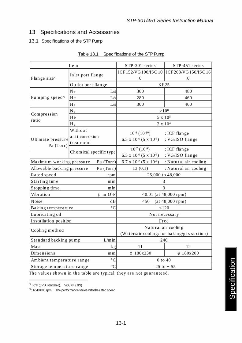
STP-301/451 Series Instruction Manual
13-1
Spe
cific
atio
n
13 Specifications and Accessories 13.1 Specif ications of the STP Pump
Table 13.1 Specif ications of the STP Pump
Item STP-301 series STP-451 series
Inlet port flange ICF152/VG100/ISO100
ICF203/VG150/ISO160 Flange size*1
Outlet port flange KF25 N2 L/s 300 480 He L/s 280 460 Pumping speed*2 H2 L/s 300 460 N2 >108 He 5 x 10⁵
Compression ratio
H2 2 x 10⁴ Without anti-corrosion treatment
10-8 (10-10) 6.5 x 10⁻⁶ (5 x 10⁻⁸)
: ICF flange : VG/ISO flange Ultimate pressure
Pa (Torr) Chemical specific type 10-7 (10-9)
6.5 x 10⁻⁶ (5 x 10⁻⁸) : ICF flange : VG/ISO flange
Maximum working pressure Pa (Torr) 6.7 x 10⁻² (5 x 10⁻⁴) : Natural air cooling Allowable backing pressure Pa (Torr) 13 (0.1) : Natural air cooling Rated speed rpm 25,000 to 48,000 Starting time min 3 Stopping time min 3 Vibration μm O-P <0.01 (at 48,000 rpm) Noise dB <50 (at 48,000 rpm) Baking temperature °C <120 Lubricating oil Not necessary Installation position Free
Cooling method Natural air cooling (Water/air cooling: for baking/gas suction)
Standard backing pump L/min 240 Mass kg 11 12 Dimensions mm φ180x230 φ180x200 Ambient temperature range °C 0 to 40 Storage temperature range °C - 25 to + 55
The values shown in the table are typical; they are not guaranteed. *1 :ICF (JVIA standard), VG, KF (JIS) *2: At 48,000 rpm. The performance varies with the rated speed
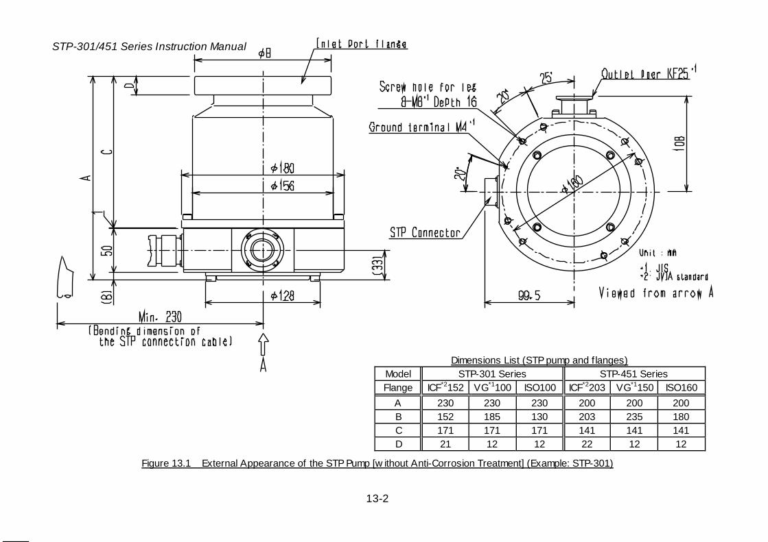
STP-301/451 Series Instruction Manual
13-2
Dimensions List (STP pump and f langes) Model STP-301 Series STP-451 Series Flange ICF*2152 VG*1100 ISO100 ICF*2203 VG*1150 ISO160
A 230 230 230 200 200 200 B 152 185 130 203 235 180 C 171 171 171 141 141 141 D 21 12 12 22 12 12
Figure 13.1 External Appearance of the STP Pump [w ithout Anti-Corrosion Treatment] (Example: STP-301)
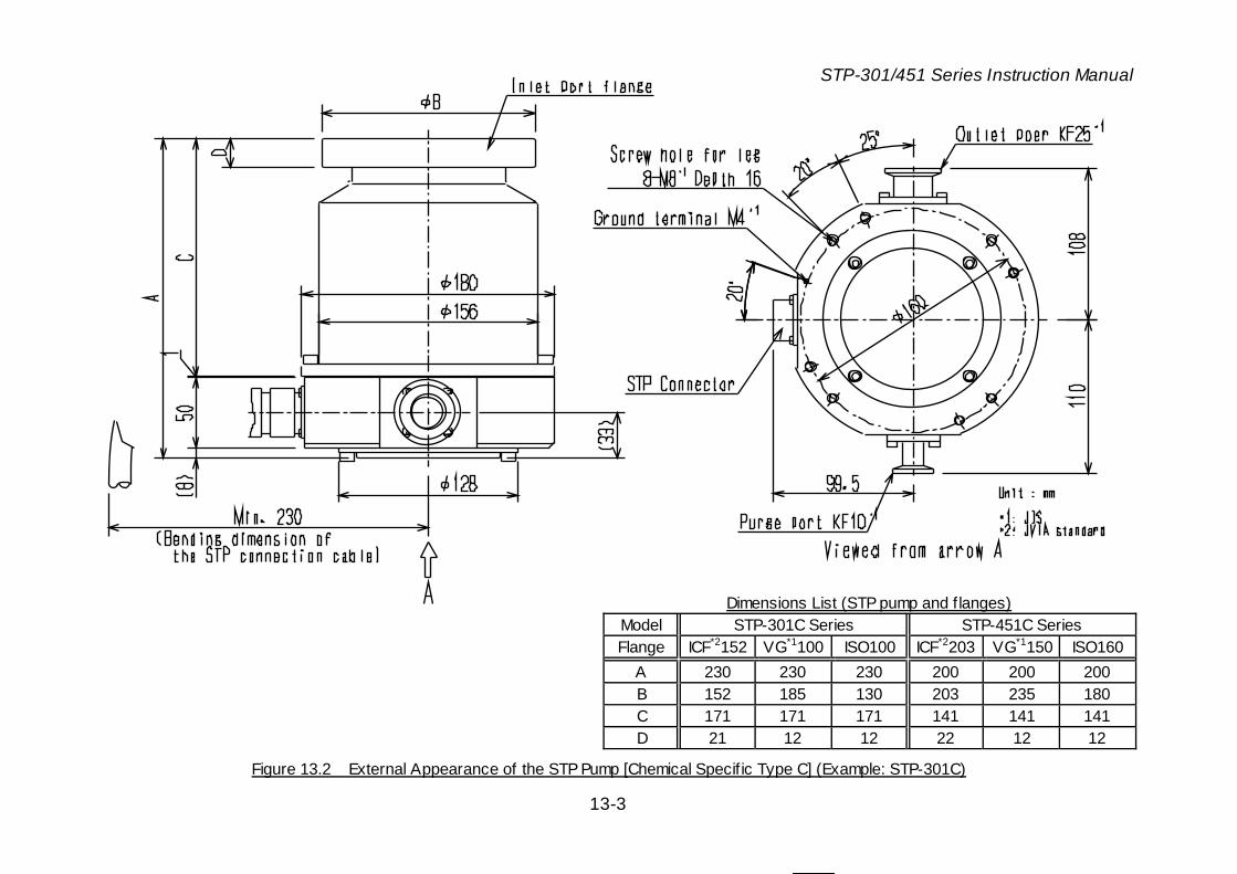
STP-301/451 Series Instruction Manual
13-3
Dimensions List (STP pump and f langes) Model STP-301C Series STP-451C Series Flange ICF*2152 VG*1100 ISO100 ICF*2203 VG*1150 ISO160
A 230 230 230 200 200 200 B 152 185 130 203 235 180 C 171 171 171 141 141 141 D 21 12 12 22 12 12
Figure 13.2 External Appearance of the STP Pump [Chemical Specif ic Type C] (Example: STP-301C)

STP-301/451 Series Instruction Manual
13-4
turbomolecular pumpSERIAL NO :
MAN UFACTURING DATE :
WEI GHT : kg
RAT ED SPEED : r pm
MANUFACTURED BY:BOC Edwards Technologies Ltd.Narashino,JapanManufactured by BOC Edwards at the formerSeiko Seiki plant in Narashino,Japan
STP-
CE
Figure 13.3 Label Aff ixing Position for the STP Pump
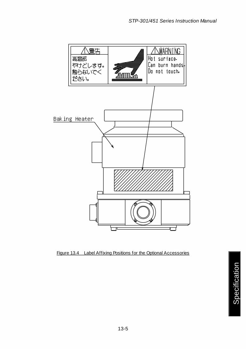
STP-301/451 Series Instruction Manual
13-5
Spe
cific
atio
n
Baking Heater
Figure 13.4 Label Aff ixing Positions for the Optional Accessories

STP-301/451 Series Instruction Manual
13-6
Specification
13.2 Specif ications of the STP Control Unit
Table 13.2 Specif ications of the STP Control Unit
Item Specifications
Input voltage VAC 100 to 120+/-10% (100V specification) 200 to 240+/-10% (200V specification)
At start: VA 550 Input power Under rated operation: VA 150
Input frequency Hz 50/60 +/-2 Leakage current value mA 3.5 Input phase Single phase
Rated current 7.5A Main breaker spec
AIC: Ampere Interrupting Capacity
1000A (AC240V, 50/60Hz)
Motor drive system 3-phase DC brush-less motor driver Output voltage under rated operation (3-phase)
VAC 31 to 62
Output frequency under rated operation
Hz 420 to 800
Ambient temperature range °C 0 to 40 Storage temperature range °C -25 to +55 Mass kg 7 Dimensions mm W209.5 x H132.5 x D315 Operation switches [Front Panel]
START switch (momentary push button, green)
STOP switch (momentary push button, red)
RESET switch (momentary push button, white)
SELECT switch (momentary push button, white)
MANUAL/REMOTE changeover switch (slide switch, gray)
Panel indication lamps ACCEL. lamp (green LED) NORMAL lamp (green LED) BRAKE lamp (yellow LED) POWER lamp (green LED) FAILURE lamp (red LED) REMOTE lamp (green LED)
Panel display LCD panel (16 characters)
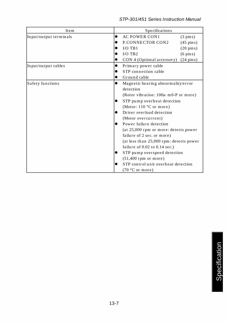
STP-301/451 Series Instruction Manual
13-7
Spe
cific
atio
n
Item Specifications Input/output terminals AC POWER CON1 (3 pins)
P.CONNECTOR CON2 (45 pins) I/O TB1 (20 pins) I/O TB2 (6 pins) CON 4 (Optional accessory) (24 pins)
Input/output cables Primary power cable STP connection cable Ground cable
Safety functions Magnetic bearing abnormality/error detection (Rotor vibration: 100μm0-P or more)
STP pump overheat detection (Motor: 110 °C or more)
Driver overload detection (Motor overcurrent)
Power failure detection (at 25,000 rpm or more: detects power failure of 2 sec. or more) (at less than 25,000 rpm: detects power failure of 0.02 to 0.14 sec.)
STP pump overspeed detection (51,400 rpm or more)
STP control unit overheat detection (70 °C or more)

STP-301/451 Series Instruction Manual
13-8
315
1.6
5122.5
5
132.5
34.85 140 34.85
209.7
29.85 150 29.85
4-φ3.6
4.85 200 4.85
25 150 25
11110.5
11
34 230 51 18
357.6
Rubber foot (4Piece)(fixed wiht screw (M4)
(150)
Figure 13.5 External Appearance of the the STP Control Unit
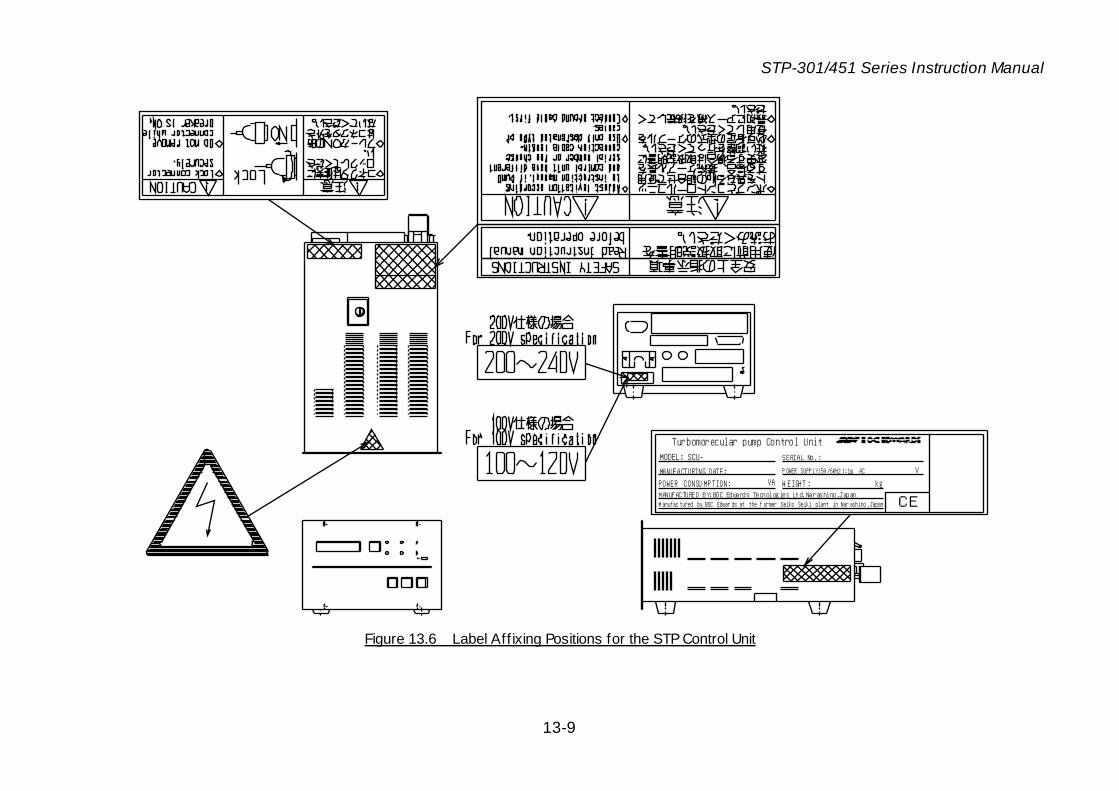
STP-301/451 Series Instruction Manual
13-9
Turbomorecular pump Control Unit
SERIAL No.:MODEL: SCU-
MANUFACTURING DATE: POWER CONSU MPTION:
P OWER SUPP LY(50 /60Hz ):1φ AC
W EIGHT : kg
VVA
M anufac tured by BOC Edwar ds at the f ormer Seiko Seiki plant in Nar ashino ,Japan .MANUFACTURED BY:BOC Edwards Tecnologies Ltd.Narashino,Japan
CE
Figure 13.6 Label Aff ixing Positions for the STP Control Unit
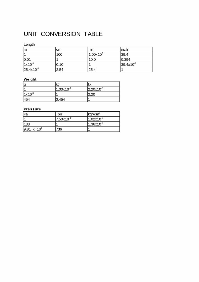
UNIT CONVERSION TABLE Length m cm mm inch 1 100 1.00x10³ 39.4 0.01 1 10.0 0.394 1x10⁻³ 0.10 1 39.4x10⁻³ 25.4x10⁻³ 2.54 25.4 1 Weight g kg lb. 1 1.00x10⁻³ 2.20x10⁻³ 1x10⁻³ 1 2.20 454 0.454 1 Pressure Pa Torr kgf/cm2 1 7.50x10⁻³ 1.02x10⁻⁵ 133 1 1.36x10⁻³ 9.81 x 10⁴ 736 1

Copyright 2003 BOC Edw ards Japan Limited. All rights reserved.
For more information, contact to the nearest Service Office.
Manufacture: BOC Edwards Japan Limited
2-4-1, Shibakoen, Minato-ku, Tokyo 105-0011 JAPAN Telephone: Domestic 03-5470-6530 International +81-3-5470-6530 Facsimile: Domestic 03-5470-6521 International +81-3-5470-6521

![[XLS]REGISTRO DE IGLESIAS - Ministerio del Interior · Web viewREFORMAS Hoja5 Consecutivo 751 - en adelante Consecutivo 601-750 Consecutivo 451-600 Consecutivo 301-450 Consecutivo](https://img.pdfslide.net/doc/110x75/5b090ddd7f8b9a93738d4f0c/xlsregistro-de-iglesias-ministerio-del-viewreformas-hoja5-consecutivo-751-.jpg)


![Abbreviated Title: F] FMISO Imaging post TACE · 2019. 2. 15. · 9000 Rockville Pike . Building 10 RM 1C495 . MSC 1180 . Phone: 301-451-4248 . Fax: 301-402-3521 . herscovitch@nih.gov](https://img.pdfslide.net/doc/110x75/60fcd8a4f7ef01227f111e3e/abbreviated-title-f-fmiso-imaging-post-tace-2019-2-15-9000-rockville-pike.jpg)


![[STP] 롯데리아](https://img.pdfslide.net/doc/110x75/55624d3dd8b42aa52d8b4c58/stp-55624d3dd8b42aa52d8b4c58.jpg)