Embed Size (px)
Citation preview
1
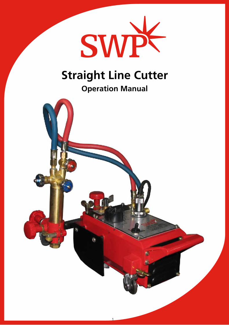
Straight Line CutterOperation Manual

2
INTRODUCTION
Read this instruction manual thoroughly to ensure correct, safe, and effective use of the machine. Co-operation between colleagues in the workplace is essential for safe, smooth operation.
SAFETY PRECAUTIONS
This product is designed to be safe, but it can cause serious accidents if not operated correctly. Those who intend to operate or repair this machine must read the manual thoroughly before use. Keep the manual near the machine so that anyone operating the machine can refer to it as necessary.
Do not use the machine without following the instructions in the manual.Use the machine only after you have read and completely understood the contents of the manual.Keep the manual to hand at all times and read it as many times as necessary for a complete understanding.If the manual becomes lost or damaged, please contact our sales office for a replacement, or your local distributor.When transferring the machine to a new owner, be sure to hand over this instruction manual.
MACHINE OPERATOR KNOWLEDGE
Operators and repair staff of this machine must completely understand the contents of the instruction manual and have completed a training course in gas welding.
3
CONTENTS
1. Safety Information 41.1 General machine safety precautions 51.2 Gas cutting safety precautions 62. Location of safety labels 93. Outline of Machine 93.1 Features of machine 94. Preparation for Operation 114.1 Contents of package 114.2 Machine assembly 124.3 Preparation for operation 135. Cutting Operation 145.1 Safety measures prior to operation 145.2 Ignition and flame adjustment 165.3 Cutting and piercing method 16
Procedures for starting cutting operation1.4 and extinguishing the flame 16
5.5 Safety measures against backfire and flashback 175.6 Cutting operation 175.7 Set up circle cutting attachment 185.8 Circle rail 186. Maintenance and Inspection 186.1 Daily inspection 186.2 Monthly inspection 186.3 3-month (2000-hour) inspection 197. Troubleshooting 198. Wiring Diagram 219. Assembly Drawing 2210. Parts List 2310.1 Main units 2310.2 Electrical, gas and torch slide holder units 2610.3 Two torch unit 2911. Cutting Data 31
4
SAFETY INFORMATION
Many accidents are caused due to a disregard of the basic safety rules during operation, inspection and maintenance. Carefully read, understand and master the safety measures and precautions outlined in this instruction manual and on the machine before operating, inspecting and maintaining the machine.
WARNING This word has been used as a warning to the user at places on the machine that could cause injury or lead to a serious accident.
CAUTIONThis word has been used to draw the attention of the user, in the form of a message and a caution label located in places that could cause slight injury or damage to the machine. They are also used as a caution to warn against frequent dangerous actions.
NOTICE SIGNSThis sign shows the machine operators and maintenance engineers items that relate directly to the damage of machines and surrounding facilities and equipment.
5
GENERAL MACHINE SAFETY PRECAUTIONS1.1
Read and fully understand the following important safety information:
MACHINE SAFETY1.1.1
The machine casing is mainly made of aluminium alloy to reduce weight. For this 1. reason, be careful not to drop heavy items on the machine, or drop the machine when carrying it as the alloy is not designed to withstand such impact.When attaching hoses to the torch and distributor, tighten the nut with the attached 2. wrench. After attaching, be sure to check there is no gas leak with a detection spray. If a gas leak is found, retighten the nut firmly, and re-check for a leak.When fixing a tip to the torch, tighten the nut with the two wrenches attached. In 3. addition, avoid damaging the taper of the tip as this may cause backfire.Never tamper with the machine other than during maintenance and inspection as the 4. machine may malfunction.Never remodel the machine. Remodelling is very dangerous.5. When changing the direction, make sure that the direction switch is in the neutral 6. (stop) position, and operate the direction switch only after the machine has stopped.Always turn the power off when not in use.7. Never use the machine outdoors in wet conditions. This will cause the machine to fail 8. and could cause a fatal electric shock.
1.1.2 SAFETY CLOTHING
1. Be sure to wear protective clothing (gauntlets, goggles, helmet and safety shoes) during operation.2. Avoid operating the machine with wet clothes or hands, to prevent chance of an electric shock.
6
1.1.3 OPERATION AND HANDLING SAFETY PRECAUTIONS
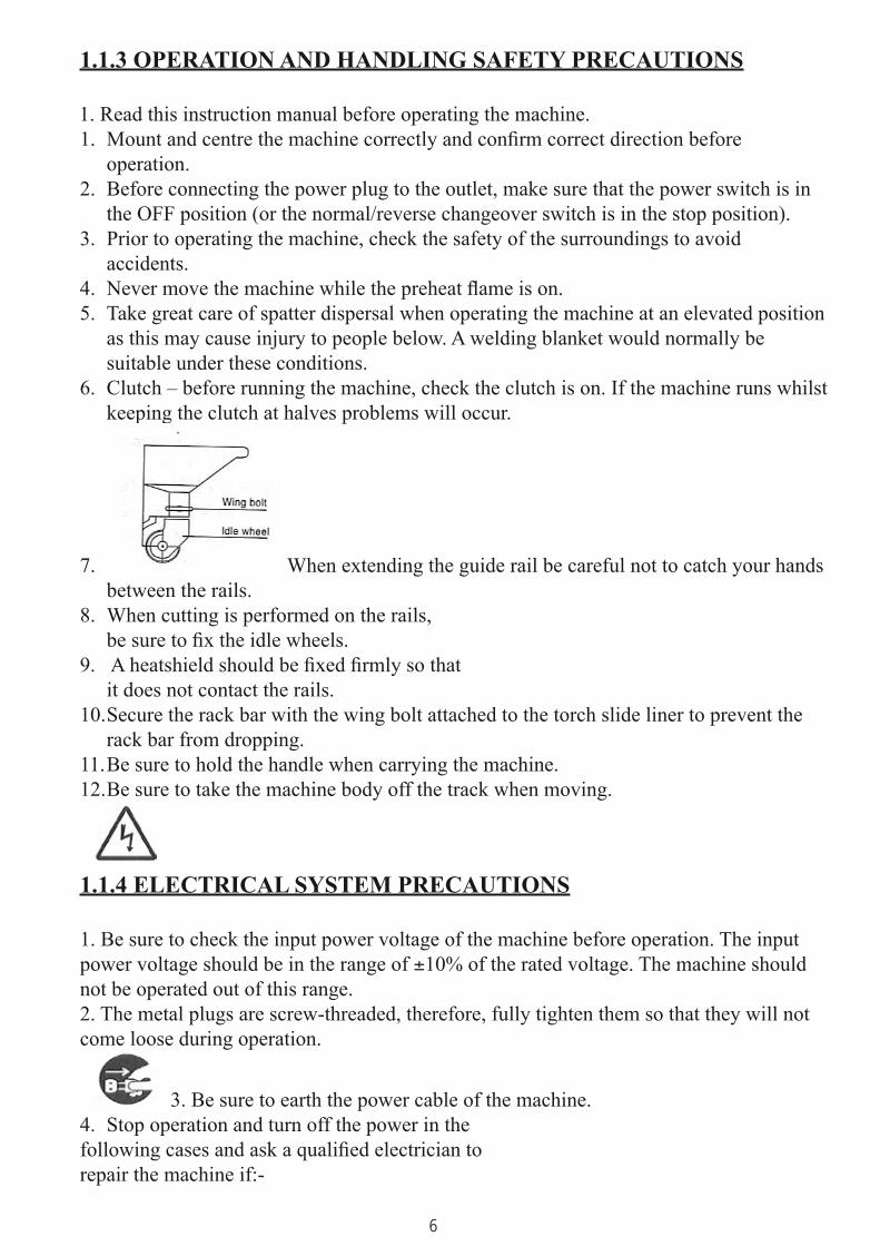
1. Read this instruction manual before operating the machine.Mount and centre the machine correctly and confirm correct direction before 1. operation.Before connecting the power plug to the outlet, make sure that the power switch is in 2. the OFF position (or the normal/reverse changeover switch is in the stop position).Prior to operating the machine, check the safety of the surroundings to avoid 3. accidents.Never move the machine while the preheat flame is on.4. Take great care of spatter dispersal when operating the machine at an elevated position 5. as this may cause injury to people below. A welding blanket would normally be suitable under these conditions.Clutch – before running the machine, check the clutch is on. If the machine runs whilst 6. keeping the clutch at halves problems will occur.
7. When extending the guide rail be careful not to catch your hands between the rails.When cutting is performed on the rails, 8. be sure to fix the idle wheels. A heatshield should be fixed firmly so that 9. it does not contact the rails.Secure the rack bar with the wing bolt attached to the torch slide liner to prevent the 10. rack bar from dropping.Be sure to hold the handle when carrying the machine.11. Be sure to take the machine body off the track when moving.12.
1.1.4 ELECTRICAL SYSTEM PRECAUTIONS
1. Be sure to check the input power voltage of the machine before operation. The input power voltage should be in the range of ±10% of the rated voltage. The machine should not be operated out of this range.2. The metal plugs are screw-threaded, therefore, fully tighten them so that they will not come loose during operation.
3. Be sure to earth the power cable of the machine.Stop operation and turn off the power in the 4.
following cases and ask a qualified electrician to repair the machine if:-
7
Input cable is damaged in anyway.1) Water leakage from the machine or liquid damage to the machine.2) Abnormal machine operation despite operating the machine according to the 3) instruction manual.Machine breakdown.4) Poor machine performance that requires repair.5)
1.1.5 MAINTENANCE AND INSPECTION PRECAUTIONS
1. Ask a qualified electrician to perform any repairs and to carry out an inspection service.2. Disconnect the power plug before inspecting and repairing the machine.3. Maintain the machine periodically.
1.2 GAS CUTTING SAFETY PRECAUTIONS
Strictly observe the safety rules and precautions to ensure the safety of gas cutting operations. Operators and supervisors MUST keep safety in mind.
1.2.1 PREVENTION OF EXPLOSION
1. Never cut pressurised cylinders or hermetically sealed containers.2. Ensure sufficient ventilation for gas cutting.
1.2.2 PRESSURE REGULATOR SAFETY PRECAUTIONS
1. Before starting operation, check that all pressure regulators are operating correctly.2. Ask a skilled repair engineer to carry out a maintenance and inspection service.3. Do not use leaking pressure regulators, nor malfunctioning pressure regulators.
Do not use pressure regulators smeared with oil or grease.4.
1.2.3 HIGH-PRESSURE GAS CYLINDER SAFETY PRECAUTIONS
1. Never use broken cylinders or leaking cylinders.2. Install cylinders upright and ensure they will not fall.

8
3. Use cylinders only for specified purposes.4. Do not smear container valves with oil or grease.5. Install cylinders in a place free from heat, sparks slag and naked flame.6. Contact the distributor if the container valves will not open. NEVER use a hammer, wrench or other tools to force open container valves.
1.2.4 SAFETY PRECAUTIONS FOR HOSES
1. Use the oxygen hose for oxygen gas only.2. Replace cracked hoses or other hoses damaged by sparks, heat, unshielded fire etc.3. Check installed hoses for kinks.4. To prevent breakage of hoses, take great care during operation and transportation.5. Do not hold the hoses when moving the machine.6. Periodically check the hoses for damage, leakage, fatigue, loose joints etc. to ensure safety.7. Cut hoses to the minimum possible length. Short hoses reduce hose damage and pressure drop as well as reduce the flow resistance.
1.2.5 SAFETY PRECAUTIONS FOR FIRE
Take safety precautions to prevent fire prior to gas cutting.Ignoring hot metal, sparks and slag could cause a fire.
1. Keep a fire extinguisher, fire extinguishing sand, bucket of water etc ready on the site where gas cutting is performed.2. Keep flammables away from the cutting area to avoid exposure to sparks.3. Always allow steel plates to cool that have become hot after cutting, as well as hot cut parts or scrap, before bringing them close to flammable materials.4. Never cut containers to which flammable materials are stuck..
9
1.2.6 SAFETY PRECAUTIONS FOR SKIN BURNS
Observe the safety precautions to prevent skin burns. Ignoring heat, spatter, and sparks during operation could cause a fire or burn the skin.
1. Do not perform cutting near flammable items. (Move flammable items well away from the sparks.)2. Do not cut containers filled with flammable materials.3. Do not keep lighters, matches, and other flammable items nearby.4. Flames from the torch may burn the skin. Keep your body away from the torch and tip and check the safety before operating the switches and valves.5. Wear correct eye and body protection.6. Correctly tighten the tip to prevent backfire.When fixing a tip to the torch, tighten the nut with the two wrenches attached.If the tip is over tightened, it will be heated during cutting and become tighter making it difficult to remove.Avoid damaging the taper of the tip since this may cause backfire.7. Using leak detector check for any gas leakages from the connection part of the distributor, hose and torch. Never use oil or grease on the connection of the oxygen pipe. This could cause a backfire which may lead to explosion.8. Be sure to check the following when igniting:Place the torch on the torch holder before igniting.Always wear the required safety protection (gauntlets, goggles, helmet etc)Check for any obstacles, dangerous materials and flammables near or in the direction of the cut.Determine the gas pressure. The gas pressure must be within the appropriate range. (For the correct gas pressure, refer to the Cutting Data.)9. The torch, tip and heat shield are heated to very high temperatures. Always wear gauntlets when handling them. After cutting the surface will be very hot; do not touch it even whilst wearing gauntlets.10. Never move the machine while the preheat flame is on.
10
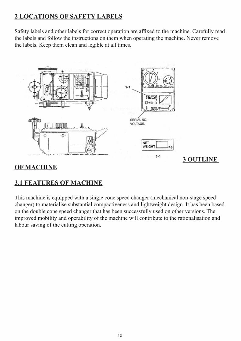
2 LOCATIONS OF SAFETY LABELS
Safety labels and other labels for correct operation are affixed to the machine. Carefully read the labels and follow the instructions on them when operating the machine. Never remove the labels. Keep them clean and legible at all times.
3 OUTLINE OF MACHINE
3.1 FEATURES OF MACHINE
This machine is equipped with a single cone speed changer (mechanical non-stage speed changer) to materialise substantial compactiveness and lightweight design. It has been based on the double cone speed changer that has been successfully used on other versions. The improved mobility and operability of the machine will contribute to the rationalisation and labour saving of the cutting operation.

11
3.2 NAME AND FUNCTION OF EACH SECTION
1. Metal receptacleUsed for connection of power cable to supply electric power.
2. Speed adjusterTurn the knob clockwise, to increase the travel speed.
3. ClutchThe lever operation will stop driving.
4. Drive switchPoint the switch in the direction of the arrow to move the machine in that direction.
5. Drive wheelEngage the clutch (ON) to transmit driving power and the machine will begin to travel.
6. Torch slide handleThis handle adjusts the lateral position of the torch.
7. HandleHold the handle to carry the machine, as well as for positioning.
8. Heat shieldThe shield protects the machine from the heating flame.
9. Idle wheel
10. Case
12
3.3 SPECIFICATIONS
Weight: 7.0 KgOne torch with body: 9.5 KgTwo torch with body: 13 KgMachine size: 350 x 140 x 175mmWheel distance: 160mmPower source: 110v (±10%)Reduction gear: Single cone systemCutting speed: 150-800mm/mmCutting edge sharp: 1.V (45°)Cutting thickness: 5-50mm (by standard accessories)Motor: 1500 r.p.m
ACCESSORIES
Cabtyre code: 1 setTip: ANM-L 1/32”, 3/64”, 1/16”Weight: 1 pc (two torch set only)Weight supporter: 1 pc (two torch set only)Fitting: 1 pc (two torch set only)
OPTION
Rail: 1.8m Extra track (9503)Circle rail: Circle cutting attachment:
4 PREPARATION FOR OPERATION
4.1 CONTENTS OF PACKAGE
The contents of the standard package are shown below. Check them carefully before assembling the machine.1. One torch setMain unit: 1 setTorch holder with rack: 1 setTorch: 1 pc
13
Gas distributor: 1 pcHose, 600mm 2 pcsCabtyre cord 5m: 1 pcTip ANM 1/32”, 3/64”, 1/16”: 3 pcs
2. Two torch setMain unit: 1 setTorch holder: 2 setsTorch: 2 pcsGas distributor: 1 pcWeight: 1 pcWeight supporter: 1 pcFitting: 1 pcHose, 600mm (2pcs) and 900mm (2pcs): 4 pcsCabtyre cord 5m: 1 pcTip ANM 1/32”, 3/64”, 1/16”: 6 pcs
4.2 MACHINE ASSEMBLY
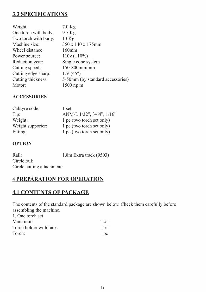
1. Take the machine out gently from the case and place it on the rail.2. Assemble the torch set parts in advance in the following order.
4.2.1 ONE TORCH SET
1. Insert the rack bar into the main unit in the

14
direction of the arrow.
2. Fit the torch holder into the rack bar.
3. Fit the torch into the torch holder and adjust the torch height setting.4. Fit the hoses between the torch and distributor connection. (The blue hose has a right-hand thread and the red hose a left-hand thread.)
5. When the torch stroke is insuffient to cut the plate beneath the rail when carrying out lower-edge preparation, change the torch holder to the position indicated by the arrow.
15
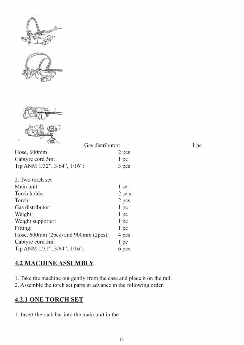
4.2.2 TWO TORCH SET
1. Insert the rack bar into the main unit in the direction of the arrow.
2. Fit the two cross-feed torch holders into the rack-bar.
3. Position and fix the torch holders in the cross-feed holders, then fit the torches.4. Fit the distributor section onto the main unit and connect and 600mm and 900mm hoses from the distributor to the two torches.5. Fix bracket, weight bar and
weight in that order. Weight
Weight bar Fix bracket
4.3 PREPARATION FOR OPERATION
4.3.1 CONNECTING THE POWER CABLE
1. Connect the power cable to the body.2. Before plugging the metal plug on the cabtyre cord side into the socket on the machine side, check there is no dust inside.3. The metal plugs are screw-threaded. Therefore, fully tighten them so that they will not come loose during operation.
4.3.2 CONNECTING THE GAS SUPPLY HOSE
16
1. Connect the respective gas supply hoses to the primary hose.2. Securely tighten the joints and check there is no gas leak.
4.3.3 CONNECTING THE TIP
Select a proper tip according to the thickness of the steel plate and attach it to the torch. (To select a tip, refer to the table of cutting data.)- When fixing a tip to the torch, tighten the nut with the two wrenches attached.
If the tip is tightened excessively, it will be heated during cutting and become tighter, - making it difficult to remove the tip.
- In addition avoid damaging the taper of the tip since this may cause backfire.
5 CUTTING OPERATION
5.1 SAFETY MEASURES PRIOR TO OPERATION
Strictly observe the safety rules, precautions and instructions to ensure safety during gas cutting operations. Operators and supervisors MUST keep safety in mind.
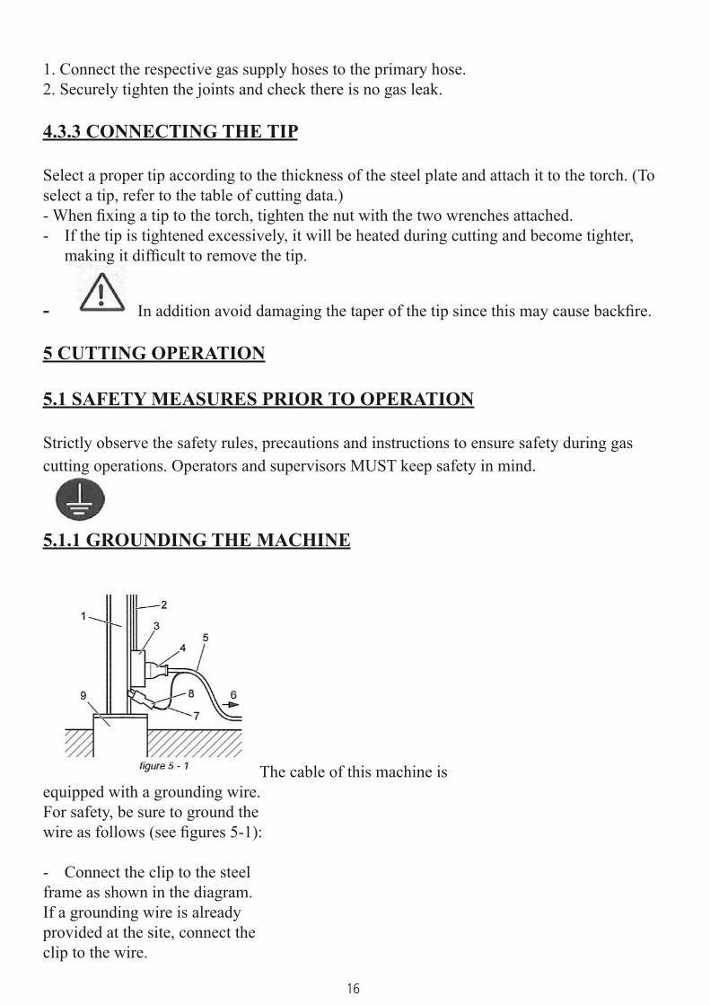
5.1.1 GROUNDING THE MACHINE
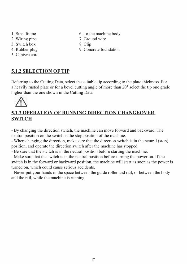
The cable of this machine is equipped with a grounding wire. For safety, be sure to ground the wire as follows (see figures 5-1):
Connect the clip to the steel - frame as shown in the diagram. If a grounding wire is already provided at the site, connect the clip to the wire.
17
1. Steel frame 6. To the machine body2. Wiring pipe 7. Ground wire3. Switch box 8. Clip4. Rubber plug 9. Concrete foundation5. Cabtyre cord
5.1.2 SELECTION OF TIP
Referring to the Cutting Data, select the suitable tip according to the plate thickness. For a heavily rusted plate or for a bevel cutting angle of more than 20° select the tip one grade higher than the one shown in the Cutting Data.
5.1.3 OPERATION OF RUNNING DIRECTION CHANGEOVER SWITCH
- By changing the direction switch, the machine can move forward and backward. The neutral position on the switch is the stop position of the machine.- When changing the direction, make sure that the direction switch is in the neutral (stop) position, and operate the direction switch after the machine has stopped.- Be sure that the switch is in the neutral position before starting the machine.- Make sure that the switch is in the neutral position before turning the power on. If the switch is in the forward or backward position, the machine will start as soon as the power is turned on, which could cause serious accidents.- Never put your hands in the space between the guide roller and rail, or between the body and the rail, while the machine is running.
18
5.2 IGNITION AND FLAME ADJUSTMENT
- Adjust the gas pressure according to the Cutting Data. The data shows the pressure when all the valves are open. Re-adjust the pressure after ignition. Flame adjustment method1. Open the fuel gas valve ¼ to ½ a turn and light the torch with an igniter.2. Then open the preheating oxygen valve gradually until a white cone of the standard flame has been obtained. (The incandescent area should be uniform and about 5-6mm (3/16-1/14”) in length.)3. Open the jet oxygen valve fully, re-adjust the flame if its condition has changed. A disorderly flow of the jet oxygen will adversely affect the quality of the cutting surface. In such cases clean the tip with a suitable tip cleaner while the jet oxygen is flowing.4. Appropriate distance between the tip end and cutting surface:- Acetylene gas 8-10mm- LPG gas 5-8mm
5.3 CUTTING AND PIERCING METHOD
1. Cut in from the end of steel plate.2. Pierce steel plate before cutting.3. Drill a hole before cutting.Piercing method1. Ignite and adjust the flame.2. Thoroughly preheat the cut-in point until it is white hot.3. Open the cutting oxygen valve to pierce the steel plate. The tip should be about 15-20mm from the plate to prevent slag from splashing onto the tip and adhering there, which will shorten the working life of the tip.
5.4 PROCEDURES FOR STARTING CUTTING OPERATION AND EXTINGUISHING THE FLAME
1. Align the tip with the cutting start point, ignite and then adjust the flame.2. Sufficiently preheat the cutting start point.3. After preheating, supply oxygen and simultaneously turn on the motor switch or the turning direction switch to start cutting.4. Carefully check the cutting condition and control the cutting speed with the speed adjuster. For the cutting speed, refer to the Cutting Data.5. Extinguish the flame after cutting as follows: 1. Turn off the motor switch (by turning direction switch) 2. Close the cutting oxygen valve. 3. Close the preheating oxygen valve. 4.Close the fuel gas valve.
19
5.5 SAFETY MEASURES AGAINST BACKFIRE
AND FLASHBACK
5.5.1 PREVENTION OF BACKFIREBackfires may cause serious accidents or fires. Be careful to prevent such disaster. When a backfire occurs, find the cause and inspect and maintain the machine correctly before using the machine again.The following are causes of backfire:1. Improper gas pressure adjustment2. Overheated tip3. Slag clogged in tip4.Damage to the tapered section of the tip or torch will cause backfire.
5.5.2 PREVENTION OF FLASHBACK
Flashback could cause fire and damage the machine. Should there be a hissing sound in the torch quickly take the following action: 1. Close the preheating oxygen valve. 2. Close the fuel gas valve. 3. Close the cutting oxygen valve.Should a flashback occur, find the cause and take the appropriate action before using the machine again.
5.6 CUTTING OPERATION
1. Attach the rail to the cutting position and align the tip with the cutting start point.2. Bring a flame close to the tip for ignition and ensure sufficient preheating.3. Simultaneously with opening the cutting oxygen valve, turn on the switch to start cutting.4. While checking the cutting condition, select the optimal cutting speed with the speed adjuster.5. After cutting, turn off the switch and close the cutting oxygen valve, fuel gas valve and preheating oxygen valve in this order.*Thereafter, repeat operations from step 1.
20
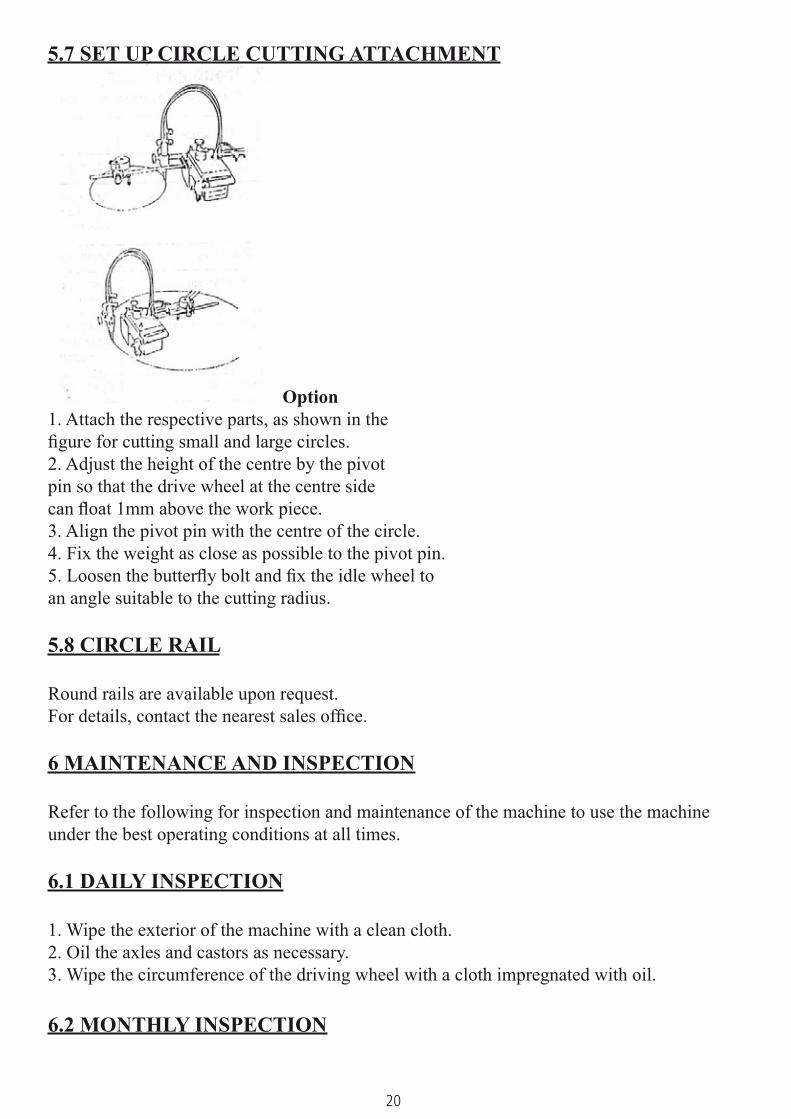
5.7 SET UP CIRCLE CUTTING ATTACHMENT
Option1. Attach the respective parts, as shown in the figure for cutting small and large circles.2. Adjust the height of the centre by the pivot pin so that the drive wheel at the centre side can float 1mm above the work piece.3. Align the pivot pin with the centre of the circle.4. Fix the weight as close as possible to the pivot pin.5. Loosen the butterfly bolt and fix the idle wheel to an angle suitable to the cutting radius.
5.8 CIRCLE RAIL
Round rails are available upon request.For details, contact the nearest sales office.
6 MAINTENANCE AND INSPECTION
Refer to the following for inspection and maintenance of the machine to use the machine under the best operating conditions at all times.
6.1 DAILY INSPECTION
1. Wipe the exterior of the machine with a clean cloth.2. Oil the axles and castors as necessary.3. Wipe the circumference of the driving wheel with a cloth impregnated with oil.
6.2 MONTHLY INSPECTION

21
1. Oil the torch slide handle shaft and clutch lever shaft.2. Measure insulation resistance in the following manner, set the switch in the forward or backward position and measure the resistance between one end of the power receptacle and the metallic part of the case. If the resistance is 5 K Ω or more, there is no problem.3. Disconnect the operation panel and remove dust from the electric equipment parts.
6.3 3-MONTH (2000-HOUR) INSPECTION
1. Remove the motor and speed change cone, replace the old grease inside the gear box with new grease.2. Replace the internal parts when they are substantially worn.3. Completely remove oil, if any, from the motor disc and speed change cone of the speed changer with thinners, etc.
7 TROUBLE SHOOTING
Note: If the motor does not rotate even after having been repaired, check that wiring is correct.Repairs are only to be conducted by a qualified professional
1. Carriage does not move (Motor does not run)
Possible cause Action SolutionPower is off Check the power source and wire
connectionBroken power cord Check the cord with a circuit tester Repair or replace
Defective plug Check wire soldering Perform solderingDefective switch Remove the mid terminal and test the
switchReplace
Defective condenser Check the condenser with a tester. If the tester handle vibrates slightly and shows immediately, the condenser is functioning properly
Replace
Defective soldering Check soldered parts Perform soldering again
Broken lead wire Check lead wire with tester ReplaceDefective motor If the test results of all the above tests are
normal, cause lies in motorRepair or replace
2 Carriage does not move (Motor runs)
Possible cause Action SolutionFaulty clutch Remove the clutch and check the inside
mechanismMount clutch properly, or replace
Slippage on frictional surface
See that pressure adjusting spring is working and that there is no oil sticking to frictional surface
Replace if spring is defective. Remove oil, using thinner if frictional surface is stained with oil

22
3. Abnormal carriage
Possible cause Action Solution1. Severe vibration and noise
1) Foreign matter caught in gear Repair or replace
2) Gear worn Replace
3) Motor faulty Repair or replace
4) Cone worn or damaged Replace
2. No disengaging Snap ring of the clutch pin is off Replace
3. Knocks 1) Gear worn Replace worn gear
2) Faulty clutch pin Replace faulty pin
3) Clutch key worn Replace worn key
4) Loose shaft or drive wheel Repair or replace
5) Worn or damaged cone Replace
6) Heat shield touched to the work surface or rail
Exercise caution
7) Damaged rail or foreign objects on rail Repair or clean
8) Hoses or power cord interferes with carriage movement
Exercise caution during operation
9) Faulty idle wheel Repair or replace
10) Foreign matter is attached to drive wheel, or this wheel is damaged
Repair or replace
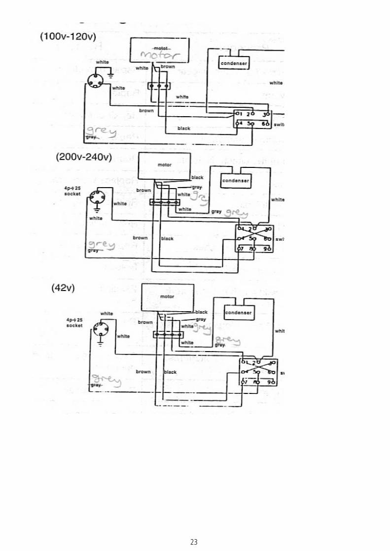
8 WIRING DIAGRAM
(100V-120V)
23
24
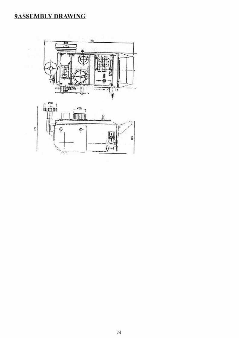
9ASSEMBLY DRAWING
25
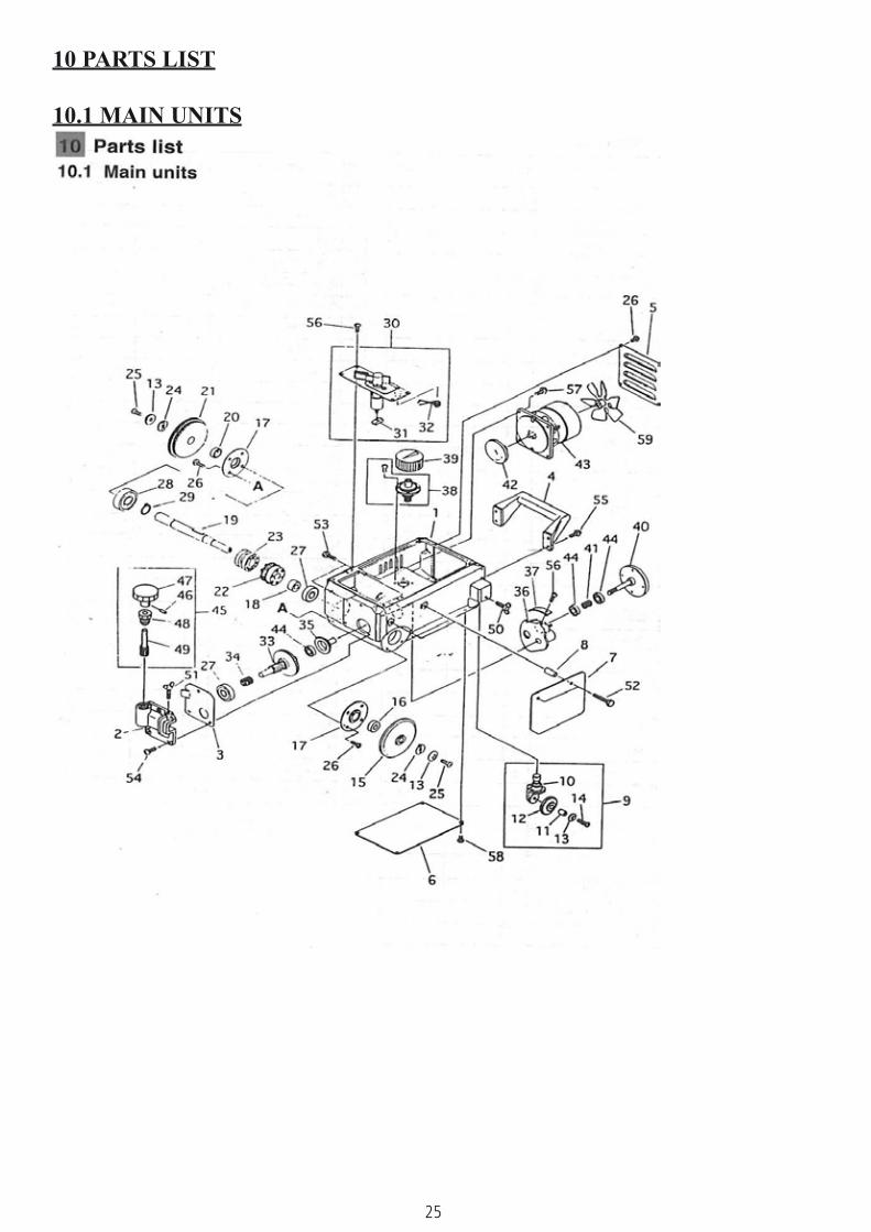
10 PARTS LIST
10.1 MAIN UNITS

26
10.1 MAIN UNITS
ITEM NO
PART NAME QTY REMARKS
1 Case 12 Cross feed holder 13 Cross feed liner 14 Handle 15 Fan cover 16 Bottom plate 17 Heat shield 18 Heat shield collar 29 Idle wheel unit 110 Idle wheel bracket 111 Roller shaft 112 Roller shaft 113 Washer 114 Screw 115 Idle wheel 116 Collar (A) 117 Bearing retainer 218 Collar (B) 119 Drive wheel shaft 1 With key20 Collar (C) 121 Drive wheel 122 Worm wheel 123 Clutch 124 Washer 225 Screw 226 Screw 227 Bearing 228 Bearing 129 Stop ring 130 Clutch lever assembly 131 Slider 132 Clutch spring 133 Worm shaft assembly 134 Worm spring35 Speed adjusting shaft 136 Speed adjusting bracket 137 Rack 138 Speed adjusting handle 139 Speed adjusting knob 140 Speed adjusting cone assembly 141 Cone spring 142 Motor disk 143 Motor 1 100V-120
Motor 1 200V-220Motor 1 230V-240
Motor 1 42V
44 Bearing 145 Cross feed pinion unit 146 Spring pin 147 Handle (∅ 40) 148 Pinion collar 149 Pinion 150 Wing bolt 151 Wing bolt 152 Hexagon bolt 253 Screw 254 Screw 355 Screw 4 With spring washer56 Screw 1057 Screw 458 Screw 859 Motor fan 1 With screw
27
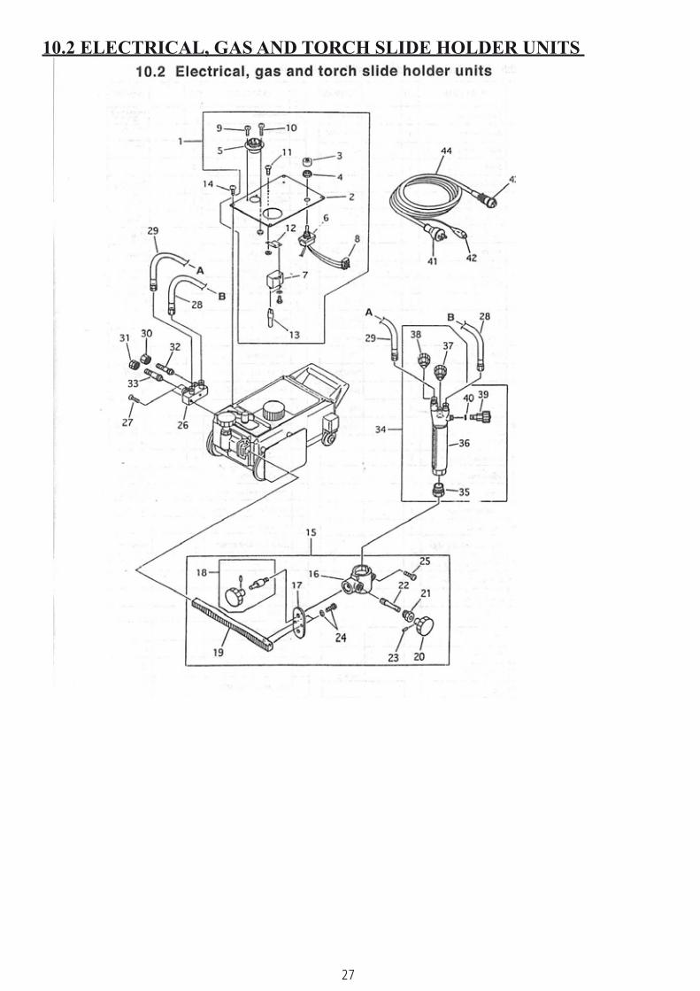
10.2 ELECTRICAL, GAS AND TORCH SLIDE HOLDER UNITS

28
10.2 ELECTRICAL, GAS AND TORCH SLIDE HOLDER UNITS
ITEM NO
PART NAME QTY REMARKS
1 Panel assembly 1 100V-240VPanel assembly 1 200V-240VPanel assembly 1 42V
2 Panel 13 Cap for dust protector 14 Nut for dust protector 15 Metal socket 1 3P
Metal socket 1 4P6 Switch 1 100V-120V
Switch 1 200V-240V42V
7 Condenser 1 100VCondenser 1 120VCondenser 1 200V-220VCondenser 1 230V-240VCondenser 1 42V
8 Terminal 1 100V-120V 3PTerminal 1 200V-240V 4P
9 Screw 2 With nut10 Screw 1 With nut11 Screw 212 Condenser fixing plate 113 Terminal 214 Screw 415 Torch holder assembly 116 Torch holder 117 Torch holder fixing plate 118 Holder fixing handle 119 Rack bar 120 Handle (∅ 40) 121 Pinion metal 122 Pinion 123 Spring pin 124 Hexagon bolt 2 With WS25 Screw 126 Distributor 127 Screw 228 Hose for oxygen 129 Hose for gas 130 Nut for oxygen 131 Nut for gas 132 Hose connector (ox) 133 Hose connector (gas) 134 Torch 135 Torch 136 Tip fixing nut 137 Rack for beetle 1 With screw38 Valve for preheat oxygen 139 Valve for gas 140 Valve for jet oxygen 141 O-ring 142 Rubber plug 143 Earth clip 1
Metal plug 1 4PMetal plug 1 4P
44 Cabtyre cord assembly 1 4PCabtyre cord assembly 1 4P
29
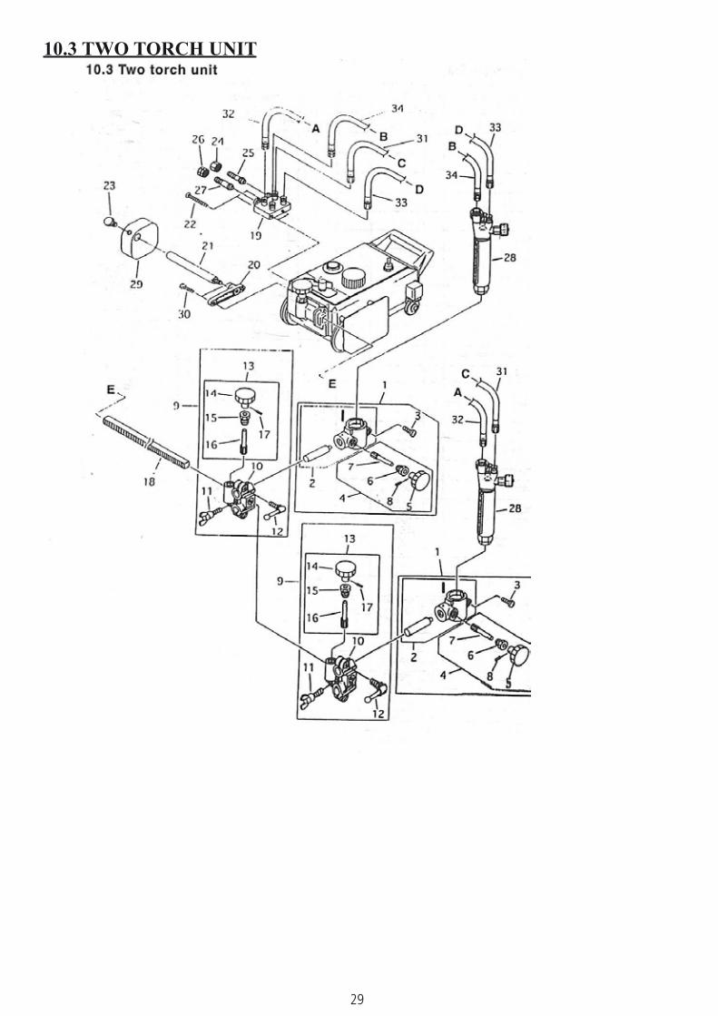
10.3 TWO TORCH UNIT

30
10.3 TWO TORCH UNIT
ITEM NO
PART NAME QTY REMARKS
1 Torch holder assembly 22 Torch holder 23 Screw 24 Torch up/down handle 25 Handle (∅ 40) 26 Pinion metal 27 Pinion 28 Spring pin 29 Torch cross feed holder 210 Cross feed holder 211 Wing bolt 212 Crank handle 213 Cross feed pinion unit 214 Handle (∅ 40) 215 Pinion metal 216 Pinion 217 Spring pin 218 Rack bar 119 Distributor 1 Europe20 Fitting 121 Weight supporter 122 Screw 223 Hexagon bolt 124 Nut for oxygen 125 Hose connector (ox) 126 Nut for gas 127 Hose connector (gas) 128 Torch 229 Weight 130 Hexagon bolt 231 Hose for oxygen 132 Hose for gas 133 Hose for oxygen 134 Hose for gas 1
11 CUTTING DATA
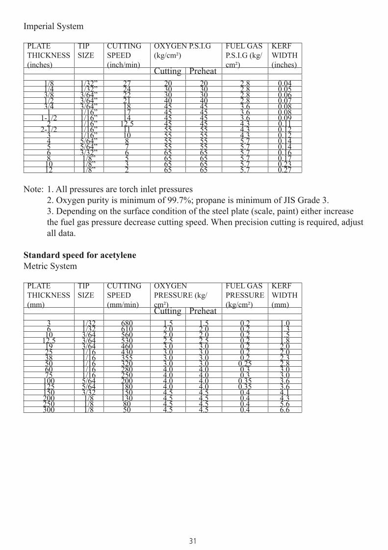
Standard speed for propane.Metric System
PLATETHICKNESS (mm)
TIP SIZE
CUTTING SPEED (mm/min)
OXYGEN PRESSURE (kg/cm²)
FUEL GAS PRESSURE (kg/cm²)
KERF WIDTH (mm)
Cutting Preheat3 1/32 680 1.5 1.5 0.2 1.06 1/32 610 2.0 2.0 0.2 1.3
10 3/64 560 2.0 2.0 0.2 1.512.5 3/64 530 2.5 2.5 0.2 1.819 3/64 460 3.0 3.0 0.25 2.025 1/16 430 3.0 3.0 0.25 2.038 1/16 355 3.0 3.0 0.25 2.350 1/16 320 3.0 3.0 0.25 2.860 1/16 280 4.0 4.0 0.3 3.075 1/16 250 4.0 4.0 0.3 3.0
100 5/64 200 4.0 4.0 0.3 3.6125 5/64 180 4.0 4.0 0.4 3.6150 3/32 150 4.5 4.5 0.4 4.1200 1/8 130 4.5 4.5 0.4 4.3250 1/8 80 4.5 4.5 0.4 5.6300 1/8 50 4.5 4.5 0.4 6.6
31
Imperial System
PLATETHICKNESS (inches)
TIP SIZE
CUTTING SPEED (inch/min)
OXYGEN P.S.I.G (kg/cm²)
FUEL GAS P.S.I.G (kg/cm²)
KERF WIDTH (inches)
Cutting Preheat1/8 1/32” 27 20 20 2.8 0.041/4 1/32” 24 30 30 2.8 0.053/8 3/64” 22 30 30 2.8 0.061/2 3/64” 21 40 40 2.8 0.073/4 3/64” 18 45 45 3.6 0.081 1/16” 17 45 45 3.6 0.08
1-1/2 1/16” 14 45 45 3.6 0.092 1/16” 12.5 45 45 4.3 0.11
2-1/2 1/16” 11 55 55 4.3 0.123 1/16” 10 55 55 4.3 0.124 5/64” 8 55 55 5.7 0.145 5/64” 7 55 55 5.7 0.146 3/32” 6 65 65 5.7 0.168 1/8” 5 65 65 5.7 0.17
10 1/8” 3 65 65 5.7 0.2312 1/8” 2 65 65 5.7 0.27
Note: 1. All pressures are torch inlet pressures2. Oxygen purity is minimum of 99.7%; propane is minimum of JIS Grade 3.3. Depending on the surface condition of the steel plate (scale, paint) either increase the fuel gas pressure decrease cutting speed. When precision cutting is required, adjust all data.
Standard speed for acetyleneMetric System
PLATETHICKNESS (mm)
TIP SIZE
CUTTING SPEED (mm/min)
OXYGEN PRESSURE (kg/cm²)
FUEL GAS PRESSURE (kg/cm²)
KERF WIDTH (mm)
Cutting Preheat3 1/32 680 1.5 1.5 0.2 1.06 1/32 610 2.0 2.0 0.2 1.3
10 3/64 560 2.0 2.0 0.2 1.512.5 3/64 530 2.5 2.5 0.2 1.819 3/64 460 3.0 3.0 0.2 2.025 1/16 430 3.0 3.0 0.2 2.038 1/16 355 3.0 3.0 0.2 2.350 1/16 320 3.0 3.0 0.25 2.860 1/16 280 4.0 4.0 0.3 3.075 1/16 250 4.0 4.0 0.3 3.0
100 5/64 200 4.0 4.0 0.35 3.6125 5/64 180 4.0 4.0 0.35 3.6150 3/32 150 4.5 4.5 0.4 4.1200 1/8 130 4.5 4.5 0.4 4.3250 1/8 80 4.5 4.5 0.4 5.6300 1/8 50 4.5 4.5 0.4 6.6

32
Imperial System
PLATETHICKNESS (inches)
TIP SIZE
CUTTING SPEED (inch/min)
OXYGEN P.S.I.G (kg/cm²)
FUEL GAS P.S.I.G (kg/cm²)
KERF WIDTH (inches)
Cutting Preheat1/8 1/32” 27 20 20 2.8 0.041/4 1/32” 24 30 30 2.8 0.053/8 3/64” 22 30 30 2.8 0.061/2 3/64” 21 40 40 2.8 0.073/4 3/64” 18 45 45 2.8 0.081 1/16” 17 45 45 2.8 0.08
1-1/2 1/16” 14 45 45 2.8 0.092 1/16” 12.5 45 45 3.6 0.11
2-1/2 1/16” 11 55 55 4.3 0.123 1/16” 10 55 55 4.3 0.124 5/64” 8 55 55 5.0 0.145 5/64” 7 55 55 5.0 0.146 3/32” 6 65 65 5.7 0.168 1/8” 5 65 65 5.7 0.17
10 1/8” 3 65 65 5.7 0.2312 1/8” 2 65 65 5.7 0.27
Note: 1. All pressures are torch inlet pressures. 2. Oxygen purity is minimum of 99.7%
3. Depending on the surface condition of the steel plate (scale, paint), either increase the fuel gas pressure or decrease cutting speed. When precision cutting is required, adjust all data.