Embed Size (px)
Citation preview

StrainersF-7, FA-7, F-15, F-30 & Steel Series
Installation and Parts
Liquid ControLs Group An IDEX Fluid & Metering Business M200-10
F and FA Series Aluminum Body Strainers
F Series Cast Iron, Stainless Steel and Brass Body
Strainers
FS, FSA and FSAA Steel Body Strainers

2
Table of ConTenTs
Publication Updates and TranslationsThe most current English versions of all Liquid Controls publications are available on our web site, www.lcmeter.com. It is the responsibility of the local distributor to provide the most current version of LC manuals, instructions, and specification sheets in the required language of the country, or the language of the end user to which the products are shipping. If there are questions about the language of any LC manuals, instructions, or specification sheets, please contact your local distributor.
! WaRnInGbe Prepared
• Before using this product, read and understand the instructions.• All work must be performed by qualified personnel trained in the proper application, installation, and maintenance
of equipment and/or systems in accordance with all applicable codes and ordinances.• When handling electronic components and boards, always use proper Electrostatic Discharge (ESD) equipment
and follow the proper procedures• Make sure that all necessary safety precautions have been taken. • Provide for proper ventilation, temperature control, fire prevention, evacuation, and fire management.• Provide easy access to the appropriate fire extinguishers for your product. • Consult with your local fire department, state, and local codes to ensure adequate preparation.• Read this manual as well as all the literature provided in your owner’s packet.• Save these instructions for future reference.• Failure to follow the instructions set forth in this publication could result in property damage, personal injury, or
death from fire and/or explosion, or other hazards that may be associated with this type of equipment.
InTRodUCTIon
Safety Procedures .................................................... 2LC Strainers Overview ............................................. 4Installation and Operation ........................................ 4Maintenance ............................................................. 5How to Order Replacement Parts ............................ 6Troubleshooting ........................................................ 7
bIll of maTeRIals
F-7 Aluminum ........................................................... 8F-7 Brass .................................................................. 9F-7 Cast Iron ........................................................... 10F-7 Stainless Steel .................................................. 11F-15 Aluminum ........................................................ 12F-30 Aluminum ........................................................ 13FA-7 Aluminum ........................................................ 14FS/FSAA/FSA Inline Configurations ........................ 15FS/FSAA/FSA Bottom Inlet Configurations ............. 15
Liquid Controls disclaims all liability for damage to meter or accessories because of corrosion, salting out of product, or separation of chemicals whether occurring during periods of use or storage.
! DISCLAIMER

3
safeTy PRoCedURes
This manual provides warnings and procedures that are intended to inform the owner and/or operator of the hazards present when using the Liquid Controls Meter on LP-Gas and other products. The reading of these warnings and the avoidance of such hazards is strictly in the hands of the owner-operators of the equipment. Neglect of that responsibility is not within the control of the manufacturer of the meter.
noTICe
Before disassembly of any meter or accessory component:• all internal pressures must be relieved and all liquid drained from the system in
accordance with all applicable procedures.• Pressure must be 0 (zero) psi. • Close all liquid and vapor lines between the meter and liquid source.
For Safety Rules Regarding LPG, refer to NFPA Pamphlet 58 and local authorities.
failure to follow this warning could result in property damage, personal injury, or death from fire and/or explosion, or other hazards that may be associated with this type of equipment.
! WaRnInGbe Preparedsafely evacuate Piping system
In The evenT of laRGe fIRes oR fIRes ThaT aRe sPReadInGn Evacuate the building and notify your local fire department.
n Stop the leakage only if you can safely reach the equipment.
In The evenT of small, ConTaIned fIRes ThaT yoU Can safely ConTRoln Stop the leakage if you can safely reach the equipment.
n Use the appropriate extinguisher: Class B fire extinguisher, water, fog, etc., depending on the materials.
n If in doubt, call your local fire department.
!In the event of
a Gas fire
In The evenT of a laRGe Gas leak n Evacuate the area and notify the fire department.
In The evenT of a small, ConTaIned Gas leakn Stop the leak and prevent accidental ignition.
n Prevent the entrance of gas into other portions of the buildings. Some gases, such as LPG, seek lower levels, while other gases seek higher levels.
n Evacuate all people from the danger zone.
n See that the gas is dispersed before resuming business and operating motors. If in doubt, notify your local fire department.
!In the event of
a Gas leak

4
InsTallaTIon and oPeRaTIon
lC strainers overviewWhaT lC sTRaIneRs doStrainers help to protect meters from serious damage caused by burrs dislodged from new piping, pipe scale or foreign material. The strainer’s initial cost is good insurance against the cost of down time and replacement parts incurred from a damaged meter. A meter strainer installed on the inlet side is necessary even when a coarse strainer on the upstream side of the pump is included in the system. Strainers are not meant to be used as a system filter but as limited protection for the meter element itself.hoW lC sTRaIneRs WoRkAs a liquid product enters the strainer housing from the supply line, it is routed through the strainer basket. The strainer basket is a two-ply screen. The inner screen is made of fine mesh of either 20, 40, 80, 100, or 200 squares per inch. The outer screen works as a backing. It gives reinforcement and support to the fine mesh inner screen.Liquid passes through the strainer and into the inlet of the meter. Any debris that is larger than the mesh in the basket is trapped in the basket. THE STRAINER IS NOT A FILTER, and the size of the mesh in the basket selected will determine the particle size that can pass through the strainer. Basket mesh selection is generally based on maximum fluid viscosity at minimum ambient operating temperature.
Relieving Internal PressureAll internal pressure must be relieved to zero pressure before disassembly or inspection of the strainer, vapor eliminator, any
valves in the system, the packing gland, and the front or rear covers.
Relieving Internal Pressure Procedure for lPG and nh3 meters6. Slowly crack the fitting on top of the differential valve to
relieve product pressure in the system. Product will drain from the meter system.
7. As product is bleeding from the differential valve, slowly reopen and close the valve/nozzle on the discharge line. Repeat this step until the product stops draining from the differential valve and discharge line valve/nozzle.
8. Leave the discharge line valve/nozzle open while working on the system.
1. Close the belly valve of the supply tank.
2. Close the valve on the vapor return line.
3. Close the manual valve in the supply line on the inlet side of the meter. If no manual valve exists on the inlet side, consult the truck manufacturer for procedures to depressurize the system.
4. Slowly open the valve/nozzle at the end of the supply line.
5. After product has bled off, close the valve/nozzle at the end of the supply line.
Serious injury or death from fire or explosion could result in performing maintenance on an improperly depressurized and evacuated system.
! WaRnInG
feaTUResLC markets a wide variety of strainers to fit most meters in terms of capacity, pipe size, working pressure and metallurgical compatibility. The design advantages of a liquid Controls strainer include:
• Strainer baskets with an unusually high open basket area to pipe area ratio, resulting in minimum restriction of flow and low pressure loss.
• Choice of 20, 40, 80, 100 or 200 mesh cadmium plated steel or stainless steel strainer baskets.
• Installation in a variety of positions, that simplify piping.• Optional 45 accessory elbows for indexing strainer inlet
positions other than right angle flow. Available for 2” F-7 Aluminum strainers only.

5
maInTenanCe
disassembling a strainer To disassemble a strainer
1. Carefully clean strainer basket cover plate to remove all foreign matter, and remove the four bolts and washers from the end cover plate.
2. Remove the end cover plate (cover plate is on the top of FS/FSAA/FSA strainers) and o-ring from the strainer housing.
3. Remove the strainer basket. This may dislodge dirt and particles into the strainer housing. Check inside the strainer housing for any foreign material. Be sure to wipe the housing clean, using a soft cloth.
4. Clean the strainer basket by flushing the basket with a liquid cleaning agent suited for your application. A soft brush may be used to dislodge imbedded particles. If the imbedded particles cannot be removed, replace the basket.
5. Clean the inner face of cover plate, mating face of the strainer body, and seal ring with a clean, soft, cloth.
6. Make sure the o-rings are cleaned of all dirt and grime. Check the o-rings for damage. If the o-rings cannot be cleaned or are damaged or frayed, replace them.
maintenanceIt is very important to follow the strainer preventive maintenance procedures to protect the strainer as well as the metering system. Foreign matter that builds up inside the strainer, including ice, can cause damage to the strainer and the metering system. When foreign matter builds up inside the strainer, it can cause pressure to build up inside the strainer. This pressure can cause the strainer screen to rupture. Foreign matter can then enter the metering chamber. This can cause serious damage to the meter resulting in failure of the meter.The following strainer preventive maintenance precedures will keep your strainer functioning properly, keep strainer repair costs to a minimum, and insure the protection of your metering system.
neWly InsTalled oR RePaIRed sysTems• Check the strainer daily during the first 100 hours of
operation or until no more debris is found in the strainer.• New or repaired piping can be the source of welding slag or
other foreign particles that can block or rupture the strainer screen.
• Once a system is cleaned out, the strainer should be checked several times every season. The frequency depends on the specific service conditions, through put and product cleanliness.
When an air eliminator is used with the strainer, it must be installed vertically on the strainer.
Air Eliminators & Strainers
Never reuse PTFE O-rings. Always replace them even if they appear to be in good condition.
Replace PTFE O-rings
Never tap the basket ends on a hard surface to dislodge particles. This may dent the basket and make reassembly
difficult or cause improper sealing.
Installation and operation1. flush all new systems
Flushing the system before the meter has been installed is the preferred first step. Thoroughly flush the lines until the system is purged of all foreign materials. See Strainer Maintenance for disassembly and reassembly instructions.
2. Plan a location for the strainer in the system providing for the following requirements: Make sure there is no pipe strain imposed upon the strainer or any other component part of the meter assembly. This means that
the meter and its accessories must not support the weight of the piping. Plan for enough space to allow clearance so that the strainer basket cover and strainer basket can be easily removed.
3. Install the strainer (1) Install the strainer on the inlet side of the meter (2) Bolt the strainer outlet to the inlet flanged connection of the meter. (3) Then bolt the inlet piping to the inlet flanged connection of the strainer.
4. Check the strainer daily during the first 100 hours of operation New or repaired piping can be the source of welding slag or other foreign material that will
block or rupture the strainer screen. or until no more debris is found in the strainer.5. Inspect and clean the strainer basket regularly
To ensure proper operation.6. follow strainer maintenance
Follow the steps outlined in the Strainer Maintenance section of this manual.
Meter Inlet Side

6
maInTenanCe
Torque Chart
Bolt SizeGrade 5 fasteners Grade 8 fasteners
Foot-Pounds NOMINAL*
Newton-Meter NOMINAL*
Foot-Pounds NOMINAL*
Newton-Meter NOMINAL*
#8 (.164) - 32 UNC-2A 2.54 (30.5 in/lb) 3.4#10 (.190) - 24 UNC-2A 3.75 (45 in/lb) 5.11/4” (.250) - 20 UNC-2A 7.3 9.9 12.5 16.95/16” (.3125) - 18 UNC-2A 15.3 20.7 26 35.33/8” (.375) - 16 UNC-2A 27 37 44 59.77/16” (.4375) - 14 UNC-2A 43 58 68.5 92.91/2” (.500) - 13 UNC-2A 66 90 112 1525/8” (.625) - 11 UNC-2A 132 179 222 3013/4” (.750) - 10 UNC-2A 233 316 395 535
*Torque Tolerance is ± 10%
To Reassemble an fs/fsaa/fsa strainer1. Strainer baskets have an extended collar, or lip on the
bottom end of the basket (C). Insert this end into the strainer housing first.
2. Place the o-ring (1) in the groove on top of the strainer housing (2).
3. Place the center hole of the basket cover plate (3) over the basket rod (4) that extends from the center of the housing. The plate should now rest on top of the basket.
4. Install the washer (5) and the wing-nut (6) on the basket rod (4).
5. Place the cotter pin (7) through the hole at the top of the basket rod (4).
6. Place the cover (8) on top of the strainer housing.7. Insert the 12 or 16 screws (9) into the cover holes (8).
Attach the flat washer (10) and nuts (11) to the screws (9) from below. Evenly tighten all nuts and screws. See Torque Chart below.
Before re-filling or re-pressurizing your meter/strainer assembly, all seal gaskets and bolts must be in place and fully tightened to prevent leakage of product out of the system. See Torque Chart below. Failure to follow
this procedure may result in a hazardous condition and possible serious injury or death.
! WaRnInG
Leakage that occurs after tightening the fasteners indicates a damaged seal, or distortion to the surface
of the cover. In either case, the seals or cover must be replaced. Excessive tightening will not stop the leakage.
Tightening Screws and Nuts
Reassembling a strainersTo reassemble a f/fa strainer
1. Replace the strainer basket (A) or (B) into the housing.2. Place the end cover o-ring (1) in the groove in the end cover
(2).3. Place the end cover (2) with the o-ring installed, on the
strainer housing end (3).4. Fasten the end cover with the 4 washers and screws (4).
Evenly tighten all screws. See Torque Chart below.

7
hoW To oRdeR RePlaCemenT PaRTs & TRoUbleshooTInG
PRoblem 1Meter lockup; rotors do not turn.
PRobable CaUse aStrainer basket rupture possibly due to improper maintenance of the strainer basket. If this occurred in a new system, the system may have been improperly flushed.
solUTIon aReplace the strainer basket and follow proper strainer maintenance procedures. New systems should be flushed. In all systems, the meter chamber will require cleaning and may require replacement of parts. Refer to your meter Installation, Operation and Maintenance Manual for meter maintenance procedures or contact your full service distributor.
PRobable CaUse bDebris entered the metering chamber possibly due to improper cleaning during strainer maintenance. (i.e. dirt dislodged into the strainer housing when the basket was removed for cleaning.)
solUTIon bProperly clean the strainer housing as outlined in the Maintenance section of this book. The meter chamber will require cleaning and may require replacement of parts. Refer to your meter Installation, Operation and Maintenance Manual for meter maintenance procedures or contact your full service distributor.
PRobable CaUse CDenting or distortion of the strainer basket which opened gaps and allowed foreign particles to pass through to the meter chamber. This is usually caused by improper handling of the strainer basket during maintenance.
solUTIon CReplace the strainer basket and follow proper strainer maintenance procedures. The meter chamber will require cleaning and may require replacement of parts. Refer to your meter Installation, Operation and Maintencance Manual for meter maintenance procedures or contact your full service distributor.
PRoblem 2Meter inspection due to meter inaccuracy revealed scoring of the meter chamber.
PRobable CaUse aSee the probable causes for Problem 1.
solUTIons aSee the solutions for Problem 1. However, if inspection does not reveal a ruptured strainer basket and it is known that proper maintenance cleaning procedures were followed, contact your full service distributor.
how to order Replacement Parts1. Refer to the exploded view drawings on pages 8-15. Find the four-digit item number of the part that needs replaced. Item numbers
are listed on the exploded drawings.2. In the red Owner’s Information Packet, you will find a computer printout titled Parts List. The Parts List lists each item number
alongside a five-digit part number. The part number identifies the specific individual piece, kit, or complete assembly used to assemble that particular meter.
3. Contact your distributor and give them the five-digit part number. Your distributor will use it to find the correct part for your strainer.
PRoblem 3High pressure drop across the strainer or loss of flow rate.
PRobable CaUse aStrainer basket screen is partially blocked by foreign material such as dried material or salted out solid particles due to drying.
solUTIon aProperly clean the strainer housing as outlined in the Maintenance section. The meter chamber may require cleaning and replacement parts. Refer to your meter Installation, Operation and Maintenance Manual for meter maintenance procedures or contact your full service distributor.
PRobable CaUse bInner mesh of the strainer basket is not properly sized for viscosity of the product.
solUTIon bReplace the strainer basket with a basket correctly suited for the product.
PRoblem 4Leaking at the strainer basket cover.
PRobable CaUse aThe seals are allowing product to leak. This is caused by a damaged o-ring or gasket seal, or reusing a PTFE seal after strainer maintenance.
solUTIon aReplace the damaged seals. Replace PTFE seals if they were reused even if they are in good condition.
PRobable CaUse bDirty areas that are preventing the seals from making complete contact.
solUTIon bClean the strainer housing as outlined in the Maintenance section. Remember to replace PTFE seals and never to reuse them.
Troubleshooting

8
f-7 alUmInUm

9
f-7 bRass

10
f-7 CasT IRon

11
f-7 sTaInless sTeel
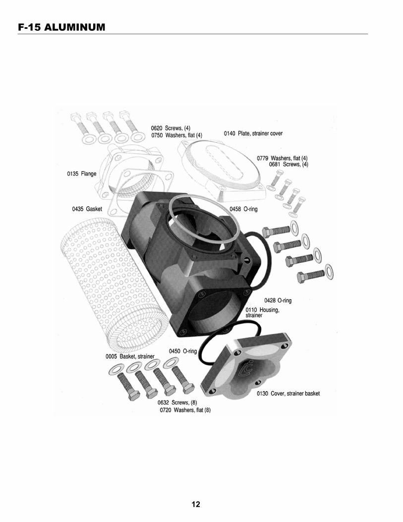
12
f-15 alUmInUm

13
f-30 alUmInUm

14
fa-7 alUmInUm
addITIon of a maGneT and holdeR To The fa-7 and fa-15 sTRaIneR assemblIesTo help alleviate the problem of premature strainer plugging and to prolong the life of the measuring chamber, we have added a cylindrical magnet and magnet holder as standard in all FA-7 and FA-15 strainers supplied with MA-5, MA-7, and MA-15 Series LPG meters starting September 15, 2004.
Magnet (PN 09387) and Holder (PN 501401)

15
fs/fsaa/fsa ConfIGURaTIons
InlIne ConfIguratIon Bottom Inlet ConfIguratIon

© 2004 Liquid ControlsPub. No. 48404D
(4/12)
105 Albrecht DriveLake Bluff, IL 60044-22421.800.458.5262 • 847.295.1050Fax: 847.295.1057www.lcmeter.com
TopTech SySTemS1124 Florida Central ParkwayLongwood, FL 32750(407) 332-1774
Nateus Business ParkNieuwe Weg 1-Haven 1053B-2070 Zwijndrecht (Antwerp), Belguim+32 (0)3 250 60 60
Liquid conTroLS105 Albrecht DriveLake Bluff, IL 60044(847) 295-1050
Liquid conTroLS europe/SAmpiVia Amerigo Vespucci 155011 Altopascio (Lucca), Italy+39 0583 24751
ideX FLuid And meTering pvT. LTd.Survey No. 256, AlindraSavli GIDC, ManjusarDist. Vadodara 391 770Gujarat, India+91 265 2631855
Liquid conTroLS SponSLer105 Albrecht DriveLake Bluff, IL 60044(847) 295-1050
FAure hermAnRoute de Bonnetable B.P. 2015472406 La Ferté-Bernard Cedex, France+33 (0)2 43 60 28 60
6961 Brookhollow West DriveHouston, TX 77040(713) 623-0808
corken3805 Northwest 36th St.Oklahoma City, OK 73112(405) 946-5576