Embed Size (px)
Citation preview

Originally published in the Proceedings of SMTA International, Rosemont, IL, September 27-October 1, 2015
Strategic Environmental Research and Development Program (SERDP) Nanoparticle enhanced conformal coating project: Coating modeling for tin whisker
mitigation S. McKeown, S. Meschter*; BAE Systems
P. Snugovsky, J. Kennedy, Z. Bagheri, J. Keeping; Celestica J. Cho; Binghamton University
D. Edwards; Henkel LLC K. Elsken; Covestro LLC
*Corresponding Author [email protected]
ABSTRACT In 2006, the European Union RoHS legislation prohibited the use of lead in many electronic systems. This has resulted in increased use of pure tin finishes and tin rich lead-free alloys in aerospace and defense electronic systems. While aerospace and defense are currently exempt from the RoHS legislation, these industries adapt or directly use many consumer parts and assemblies. Unfortunately, the tin rich materials in these consumer items have a higher short circuit risk due to tin whiskers than heritage tin-lead materials. The whisker shorting potential can be mitigated by applying conformal coatings traditionally used for moisture protection to electronic assemblies. However, tin nodules and odd-shaped eruptions can also form, which can rupture the coating and reduce moisture protection and whisker mitigation effectiveness. The application of conformal coating to the original “tin free” surface alters the surface, changing the whisker nucleation and growth characteristics. A combination of finite element, classical plate deflection and adhesion models have been developed to examine the critical pressure that a tin nodule/whisker can exert on a coating before rupture or delamination occur. Supporting experimental results reveal that a high strength high modulus polyurethane conformal coating can inhibit nodule/whisker formation provided the coating is sufficiently thick and well adhered to the tin.
Key words: Tin Whiskers, Lead Free, Mitigation, Conformal Coating
BACKGROUND
Tin whisker growth generally occurs when thin tin or tin rich alloys are under “compressive” stress. As shown in Figure 1, whisker growth can occur due to stress sources such as copper substrate intermetallic (IMC) growth, corrosion/oxidation, differences in coefficient of thermal expansion under thermal cycling conditions, and from mechanical loads [1]-[3]. While much of the reported whisker growth has been on tin plating, lead-free solder can also grow whiskers, particularly where it is less than 25 microns thick [4][5][7] (Figure 2). Equipment in harsh service conditions experiences thermal cycling, vibration, shock, humidity, salt fog, sulfur rich environments,
rework, and long term storage, which can all contribute to whisker growth.
The formation of tin whiskers can result in short circuits which are difficult to find and cause unexpected system behavior [8]. The aerospace and defense electronic systems recognize the potential impact of tin whisker shorting and utilize multiple mitigations to reduce the risk. Mitigations include lower whisker propensity material combinations, barriers, spacing, conformal coating, and redundant system design [9].
Figure 1: Some sources of compressive stress contributing to whisker growth.
Tin
Tin
IntermetallicCopper
High Tin Expansion
Low Expansion Substrate
Intermetallic Growth Stress
Use, Storage and Thermal Cycling
Thermal Expansion Difference Stress Power Cycling,
Thermal Cycling
Corrosion/Oxidation Stress
High Humidity, Corrosive Conditions
Corrosion and/or oxidation product
Mechanical load
Mechanical Stress Clamping, Screw
Tightening, Connector Contact
Pressure

(
(FwlpsinbScc1 CruatyABDhmekcg
(A)
(B)Figure 2: SEwhisker growthead terminatio
pack (cleaned soldering) aftendicates a br
between the prSOT5 (cleanedcontamination contamination 16,910 hours of
Conformal coreliability electused extensiveaerospace and ypes have b
Association Bannockburn, Defense] and has been obsmitigation of environmental kinetics on thecoating, prevengrowth (Figure
EM images oh of Sn3Ag0.5ns to Cu boardpart before a
er 4,000 hourroken whiskerinted wiring bd part before a
of 10 micrafter assemb
f 25ºC/85%RH
ating is partitronics manufaely to providdefense electr
been qualifiedConnecting
IL and MIL-Ivarying whisk
served [10] tin rich lead-attack, alterin
e tin surface, cnting contact fr
3).
of corrosion/o5Cu (wt%) soldd pads. (A) A 6assembly and rs at 85ºC/85r that has nboard pads, 10ssembly and loogram/in2 equbly cleaning)
H, 3,500X [7].
icularly appeaacturers becaude moisture ronic systems. d [see IPC-
Electronics -46058, U.S. Dker mitigation– [19]. Coa
-free materialsg the tin whis
capturing whisrom adjacent su
oxidation anddered Cu alloy
64 pin quad flatcleaned after
5%RH. Arrownearly bridged00x [6]. (B) Aow level NaCluivalent ionic
exposed for
aling to highuse it has been
protection inMany coatingCC-830, IPC
Industries,Department of
n effectivenessating providess by reducingsker nucleationkers under theurface whisker
d y t r
w d A l c r
h n n g C , f s s g n e r
Figu
The rby surethacrylcoatipenet
Someactuastudion acpopuappliunifoparamcharaobsershadoand vgravimotivcoverefforcover
One been brasspolyu5750an 11
Bw
(A)
CoH
(B
(C
ure 3: Coating w
results of coatiseveral investihane coatings lic and siliconeings tended totration [10] – [
e researchers al electronic aies revealed thctual electroni
ular and econied with spraormity of a meters, the acteristics, anrvations are owed areas) orvertical servicity thinning). vated an efforage througho
rts to developrage [18].
of the longesunderway at N
s substrates wurethane, Ara
0). The coating1 year period o
Tin
Buckled whisker
Coa
Coating
Whisker nuclea
orrosive environmH2O, NaCl, SO2, e
B) Coating tent c
C) Coating preve
whisker mitiga
ing whisker peigators found
exhibited be coatings. In a exhibit a lon[19].
have evaluateassemblies [10hat the coatingic assemblies vnomical coatinay processes.coating inclu
coating vind assemblyareas with nr very thin coaces influenced
These assemort to understaout the electrop enhanced
st coating mitNASA Godda
were coated wathane TM 57gs were not penof office ambie
ating elongation/c
ation and growt
Coating reduceionic trans
ment: etc.
captures whisk
Yieldewhisk
ents whisker pe
ation modes.
enetration resisthat Parylen
etter performaddition, thick
nger time befo
ed coating mit][18][19]. The
g coverage andvaries greatly.ngs are liquid Factors affe
ude applicatioiscosity and
y geometry. no coverage (ating (e.g. outsi
by surface tembly observatand the curre
onics industry coating prop
tigation experiard [16] [17]. with the soft 750 (Formerlynetrated by whent testing as l
creep
th inhibited
Whisker nucleakinetics altered
surface
es moisture and sport to tin
ker
ed er
enetration
Nanoparticles improve coat
penetrationresistance
stance tests ne TM and
mance than ker stronger re whisker
tigation on e assembly d thickness . The most d coatings
fecting the on process d wetting
Common (e.g. spray ide corners ension and tions have ent coating
[20] and erties and
iments has Tin plated and tough y Uralane iskers over long as the
ation at tin
can ing n e

coatings were at least 50 microns thick. The researchers at NASA Goddard observed that the whiskers lifted and peeled the coating forming a tent until the whisker buckled or the coating failed. Some key aspects of conformal coating whisker mitigation modeling were given by Kadesch and Leidecker [16] (Figure 4).
Figure 4: Tin whisker buckling under coating.
COATING TIN WHISKER MITIGATION MODELING
The factors influencing tin nodule formation and/or tin nodule/whisker suppression under coating are not captured with a whisker buckling type of model. The development of a whisker or nodule under the coating causes pressure to be applied to the coating. The pressure application diameter could vary several orders of magnitude depending upon the type of tin growth. The diameter of a tin whisker can range from less than a micron to 20 microns. In the case of a nodule or an odd shaped eruption, the diameter can be on the order of 100 microns.
In this analysis, a combination of finite element, classical plate deflection and adhesion models are used to examine the critical pressure that a tin nodule/whisker can exert on a coating before rupture or delamination occur (Figure 5).
Coating analysis was based on three approaches:
A. Non-linear finite element analysis (FEA) to calculate the deflection in the coating to determine if the coating will rupture
B. Classical non-linear (plastic hinge) analysis to determine the deflection in the coating for comparison to the previous approach
C. Classical analysis to determine the energy release rate to delaminate the coating to determine in the coating will blister
Assumptions
The following assumptions were used in the analysis:
The pressure exerted as a tin whisker develops is equal to the yield strength of tin
Membrane deflection under pressure is neglected in the energy release rate calculations because the thinner coatings typically affected by membrane behavior would likely rupture and therefore not be influenced by delamination
The outer boundary of the disk used in the energy release calculation is fixed initially but then limited to a critical bending moment value defined by plastic hinge behavior
Yielding for the plastic hinge is elastic/perfectly plastic
Figure 5: Schematic diagram of tin growth forming a dome in the coating.
Symbols and nomenclature
a = Outer Radius of Whisker/Radius of Applied Pressure r = Variable Radius E = Modulus of Elasticity = Poisson’s Ratio h = Coating Thickness w = Deflection (subscripts described in text) Ma , Mcrit = Moment at Radius , Critical Plastic Hinge Moment p = Pressure Applied from Whisker pcrit = Critical Whisker Pressure r, = Radial, Circumferential Stress 1, 2, 3 = Principal Stresses vm = Von Mises Stress crit = Critical Stress rv = Radial-vertical Shear Stress Ks = Shear Stress Effectiveness Factor Km = Plastic Hinge Moment Factor G = Energy Release Rate, Shear Modulus (temporary variable)
Analysis and Modeling The analysis is based on applying pressure in a circular area to represent the nascent tin whisker in a method similar to that used by B.T. Han [22] using the yield strength of tin (11 MPa [23]) as the applied pressure. Coating data was based on measurements by Cho [12] simplified into a bilinear curve (see Figure 6). The numerical value of the elastic modulus for coating below
a
Tin Whisker
FB Coating
L
T
Nodule/whisker growth surface
C
d
FPEEL
FPEEL = coating peeling force FTB = whisker buckling force
T = coating thickness d = whisker diameter L = whisker length C = coating circumference peel ring
Coating
h
Tin 2a
Tin growth
r
Coating adhesion force
Fixed boundary
p

th3Pbah
F ATr3asbc(wtha1an
F7
F B
he yield point 34.5 MPa, andPoisson’s ratiobased on the attempt to maxhigh measured
Figure 6: Coat
A. Coating FEAThe coating wrectangular pa30,713 nodes actual node anspecific geomebased on dimenconstraints w(centerline), thwas applied to he action of th
analysis was c15, 30, and 45and seven micrnonlinear, an it
Figure 7: Finit7 µm)
Figure 8: Mod
B. Classical De
was 500 MPa;d the tangent o for the coatin
“rubbery” natximize the indhardness value
ting Tensile Da
A to Determinewas modeled arabolic elemand 10,080 elnd element coetry which wnsions using anere applied
he right boundthe lower surf
he tin “nodule/wonducted for n microns and rons. Because erative solution
te element mod
del boundary co
eflection Calcu
the yield stresmodulus as 7ng was estimature of the mdentation stiffnes.
ata Simplified M
e Coating Defleusing axisym
ments using lements (see Fount varied ba
was automatican ANSYS macalong the l
ary was fixedface (red arrowwhisker” (see nodule/whiskecoating thicknthe coating p
n was required
del (Diam. = 45
onditions
ulations
ss was taken as.29 MPa. Theated as 0.4999
material and tofness based on
Model.
ection metric 8-nodeapproximately
Figure 7). Theased upon theally generatedcro. Symmetryleft boundary
d, and pressurew) to representFigure 8). The
er diameters ofnesses of threeproperties wered.
5 µm, Thick. =
s e 9 o n
e y e e d y y e t e f e e
=
Coaticonsishearrelatithe oplastiwherthe ystressthe chalf plasticriticcrossbegin
Figu
Bendvariaequat
Gene
Defle
Plate
Mom
The simp(Ma
limite
Stress Relative
to Yield Stress
wb
wb
D
Ma
ing deflectionidering the coar and bending dionships includ
outer edge to alic hinge is a re the bendingyield stress ans, e.g. elastic-p
cross-section isin tension at yic hinge allow
cal moment. Ts-section is 1.ns.
ure 9: Plastic hi
ding deflectionable edge mtions:
eral Deflection
ection at center
e stiffness:
ment at edge for
above equatioply supported c
= -a2p/8). Wed by the p
Fully Yielded
a2
r2
(64
a4
5( )
64 D 1( )
E h3
12 1 2
a2
p
8
n was deterating as an axisdeflection included a bendingllow considera
considerationg stress is consnd then remaiperfectly plast
s fully yielded yield stress), twing unlimitedThe critical m.5 times the m
inge stress ver
n for a disk witmoment is giv
n due to bendin
r (r = 0):
r fixed edge (li
ons correctly pcase (Ma = 0)
When yielding lastic hinge
Relative Distance from
Partly Yielded
5 ) a2
r2
(
4 D 1( )
)p
a2Ma
2 D (
rmined analytsymmetric diskuded. Bendingg moment appation of a plastin for beams isidered to incrin constant attic, (see Figure(half in compr
the beam is cod bending rot
moment for a rmoment wher
rsus position.
th uniform presven by the
ng:
imited by plast
predict deflectiand the fixedoccurs, the m
effect describ
Neutral Axis
Yield Initiation
1 ) pM
2
a
1 )
tically by k with both g deflection plied along ic hinge. A in bending rease up to t the yield e 9). Once ression and onsidered a tation at a rectangular re yielding
ssure and a following
tic hinge):
ion for the d edge case moment is bed above.
Elastic
a a2
r2
D 1( )

Although the bending deflection equations produce good results for thin disks of coating, thicker coatings require consideration of shear deflection as follows:
General deflection due to shear:
Deflection at center (r = 0):
Shear modulus:
It should be noted that the above shear deflection equations produce results 2/3 of the values given by Volterra and Gaines [24] this is because the reference used the peak shear stress (1.5 times average) in the cross-section to calculate deflection but better agreement with finite-element results is obtained by using the average shear stress. Stresses due to bending at the outside edge of disk are given by the following relationships:
Radial stress:
Circumferential stress:
Initial attempts at plastic hinge calculations using the above equations compared well to finite-element results for thin coatings but showed considerable divergence for thicker coatings. Including shear stress given by the following equation improved agreement:
Radial-vertical shear stress:
Ks in the above equation is the shear stress effectiveness factor, and represents the effectiveness of shear in the Von Mises stress calculations. Theoretically the shear stress in a rectangular cross-section varies from zero at the top and bottom edges (where bending stress is highest) to 1.5 times average shear stress at the centerline. Although shear has no effect on the maximum Von Mises stress when yielding first occurs (because shear stress is zero, shear becomes important as the region of yielding moves toward the center of the cross-section. The specific value of Ks is empirically derived from the critical pressure determined by finite-element analysis. The shear stress is combined with the radial stress to determine the principal stresses, which are in turn used to determine the Von Mises stress as follows:
Substituting:
Von Mises Stress:
Substituting:
Solving for Ma and using a critical stress for the Von Mises stress can derive a critical moment, which is used to establish the critical plastic hinge moment:
The Km in the above equation represents the ratio between the plastic hinge moment and that at which yield initiates. Theoretically, for a rectangular cross section in pure bending with elastic-perfectly plastic material behavior this value is 1.5 but stress combinations and the specific stress-strain curve can cause some variation. The specific value of Km is empirically derived from the deflection obtained by finite-element analysis. From the above equations, it can be seen that there is a critical pressure that results in an unstable (imaginary) result. This critical pressure is obtained by setting the relationship under the radical to zero and solving for pressure:
wsp a
2r
2
4 G h
wsa
2p
4 G h
GE
2 1 ( )
r
6 Ma
h2
3 a
2 1 ( ) p 24 Ma
4 h2
rv
Ks a p
2 h
1
r
2
r
2
2
rv2
2
r
2
r
2
2
rv2
3
3
3 a2
1 ( ) p 24 Ma
4 h2
3
3 a2
1 ( ) p 24 Ma
4 h2
2
3 Ma
h2
Ks2
a2
4 h2
p
2
9 Ma2
h4
3
3 a2
1 ( ) p 24 Ma
4 h2
2 vm2
1 2 2 1 3 2 2 3 2
2 vm2
3 3
2 6 3
8 h4
a
4
3 Ks2
2 h2
a
2
p2
9 Ma a
2 1( )
h4
p72 Ma
2
h4
M aa
2 1( )
16
p64 h
4 vm2 p
2a
427 2 54 27 48 Ks
2 a2 h
2
48
Mcrit Km Ma
vm crit
Mcrit Kma
2 1( )16
p64 h
4 crit
2 p
2a
427
2 54 27 48 Ks
2 a
2 h
2
48
0 64 h4
crit2
p2
a4
27 2
54 27 48 Ks2
a2
h2
C. Energy Release Rate Calculations to Determine Coating Blistering Energy release rate was determined by using the following steps by modeling the coating as an axisymmetric model of a disk:
1. Calculate the deflection of the coating in terms of thickness, radius, pressure, and material properties considering bending, shear, and bulk compression (membrane deflection is neglected as described in the assumptions)
2. Use the calculated deflection to determine the change in volume of the front surface of the coating and the energy absorbed by the coating
3. Differentiate the energy with respect to radius and divide by circumference to determine the energy release rate
C.1 Deflection Calculation The bending deflection of a circular plate with radius=a fixed at the edge with a uniform pressure is given by [24]:
The shear deflection for a similar plate is given by:
The total deflection is obtained by summing the individual deflections and expressing the plate stiffness (D) in terms of the elastic modulus (E):
C.2 Volume Change and Energy Calculation The volume change of the surface of the coating is determined by integrating the deflection over the radius as follows:
The coating energy is then calculated as follows:
C.3 Energy Release Rate Calculation The energy release rate is determined by differentiating with respect to the radius of the applied pressure (a) and dividing by the circumference as follows:
ANALYSIS RESULTS
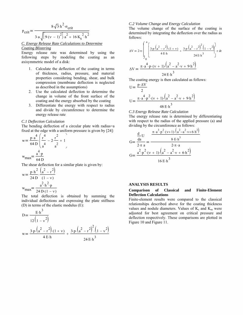
Comparison of Classical and Finite-Element Deflection Calculations Finite-element results were compared to the classical relationships described above for the coating thickness values and nodule diameters. Values of Ks and Km were adjusted for best agreement on critical pressure and deflection respectively. These comparisons are plotted in Figure 10 and Figure 11.
pcrit
8 3 h2
crit
3 a 9 1( )2
a2
16 Ks2
h2
wp a
4
64 D
r4
a4
2r
2
a2
1
wmaxa4
p
64 D
wp h
2
24 D
a2
r2
1 ( )
wmaxa
2h
2 p
24 D 1 ( )
DE h
3
12 1 2
w3 p a
2r
2 1 ( )
4 E h
3 p a2
r2
2 1 2
24 E h3
V 2
0
a
r3 p a
2r
2 1 ( )
4 E h
3 p a2
r2
2 1 2
24 E h3
r
d
V a
4 p 1( ) a
2a2 9 h
2
24 E h3
Up V
2
U a
4 p
2 1( ) a
2a2 9 h
2
48 E h3
Ga
Ud
d
2 a
a3 p
2 1( ) a2
a2 6 h
2
8 E h3
2 a
Ga2
p2
1( ) a2
a2 6 h
2
16 E h3
F
F
Figure 10 – Co
Figure 11: Com
omparison of e
mparison of ma
lastic/perfectly
aximum tensile
y plastic FEA a
e at maximum
and classical m
elongation FE
models.
EA and classicaal models

AFiuAecd(01cgd
Fc
ESed(0pnmod1sthin
Analysis resultFrom the plots s a critical pres
unstable as cAnalysis was cequation for thcoating strengthdiameters (up (see Figure 12)0.4999) coating11 MPa (tin yiecoating thicknegreater than 34diameter.
Figure 12: Ccoating thickne
Energy ReleasSimilar to the energy release diameters (up (see Figure 13)0.4999) coatingpressure of 11 not delaminatemicron and theof 14-15 µJ/mmdiameter. (Note14-15 µJ/mm2 since during tehe polyurethanterface.)
ts for coating in the previousssure where thconfirmed by conducted by
he critical stresh required for to 30 microns
). Here it can bg with a Ks valeld strength), thess greater tha.5 MPa for nod
Critical coatingess
se Rate Calculcoating ruptu
rate is calculato 30 microns
). Here it can bg with an elasti
MPa (tin yiel with a coatine critical adhem2 [21] for node that the authcritical adhes
esting the interane failed befo
rupture s section, it is ce coating defle
both classicsolving the crs to determinefive different ns) as a functioe seen that for ue of 0.846 anhe coating willan 5.5 micron dules less than
g strength re
lation Results ure approach, ated for the sams) as a functioe seen that for ic modulus of 5ld strength), thng thickness grsion energy odules less thanors in [21] ind
sion energy is rface between ore the polyu
clear that thereection becomescal and FEAritical pressuree the minimumnodule/whiskeron of thickness
a rubbery (ν =nd a pressure ofl not fail with aand a strength
n 30 microns in
equired versus
the minimumme five noduleon of thickness
a rubbery (ν =500 MPa and ahe coating willreater than 4.5f polyurethane
n 30 microns indicated that the
a lower limitthe epoxy and
urethane to tin
e s . e
m r s = f a h n
s
m e s = a l 5 e n e t d n
Figuthick A SI
An iwhiskre-enenhantin wdescrbe su
CoatThe polyupolyuformsolidpolyuin tdispe(DesmMatebase suspecrossHighfaciliThe PC18becaustren
CantThe C110specireceithick
ure 13: Criticakness
IMPLE EXPE
initial experimker mitigation
nforced polyunced strength.
whisker growthribed in these ummarized nex
ting Formulatconformal
urethane resinurethane resin
mulated to haved physical propurethane (modthis formulatiersed in a hexamodur® XP2
erialScience)) tpolyurethane
ension were fslink with theh-speed disperitate particle d
present w8M+30%XP27use it had the
ngth of the com
tilever beam wcantilever bea
0 alloy coppeified to be fiveived at 20 mkness for whisk
al energy rele
ERIMENT
ment was pern effectivenessurethane con The coating fh experimentareferences and
xt.
tion coating was
n with a nanopsystem was c
e a wide rangeperties. Moistudified PC18M, ion. The siliamethylene dii742, from Cothat is chemic
e systems. Thfunctionalized
e polymer charsion or sonicdispersion in
whisker coup742 (9.75wt%e highest elas
mpositions teste
whisker coupoam coupon hader (see Figuree to eight micromicrons whichker growth. No
ease rate vers
rformed to evs of a nanosilinformal coatiformulation [1
al [18] details d key points w
prepared bparticle suspenchosen becausee of liquid vis
ure curable sol from Henkel)ica nanopartiisocyanate (HDovestro (formeally compatibl
he nanoparticlwith an isoc
ains in the bacation was emthe suspension
pon work % nanosilica)stic modulus aed (See Append
on d bright tin ple 14). The plons thick but wh is above thote that a brigh
us coating
valuate the ica particle ings with 1][12] and have been
will briefly
by mixing nsion. The e it can be scosity and lvent-based ) was used cles were DI) system erly Bayer le with the les in the cyanate to
ase system. mployed to n medium. used the ) coating and tensile dix A).
lating over lating was
was actually he optimal ht tin plated

C[g[cPolimorPruinm
Tthmo
Fcf
WinOmms
Tfan
C110 alloy als14] in an effor
growth than 15][16][17]. T
coupons were sPC18M+30%Xobtain a final iquid coating a
minimum of 30of two hours relative humidPC18M datashremoved alonguncoated tin pln the center o
microns near th
The coupons what clamped o
mm free end dof 11.4 MPa ne
Figure 14: Cancantilever beamfixture. Dimens
Whisker counspection resu
Optical inspecmicroscope (Smetallurgical csample.
The coated coufor 500 hours and nodules onnodules under t
Side v
(B)
(A)
Clam
25
Clamp area
so was used inrt to evaluate s
the bright The tin platesolvent cleaned
XP2742 using nominal thick
application, the0-45 minutes anat 60 ºC in aity of 30 perceet. After coat
g two long edglating. The coaof sample andhe internal beam
were then instaone end and radisplacement reear the clamp.
ntilever beam m, and (B) csions in mm.
upon enviroults ction up to SEM) inspeccross-sectioning
upon was initiand inspected.n the non-coatthe coating. Th
view
p Free e
5647.5 b
3.18 no coat
boarder Cfr
Coa
Co
n other long-tslower more re
tin over bed copper cand and then drashims and a d
kness of 100 me samples werend then cured fan oven havincent in accordting air dryingges of the couating was 100 d thinned to lm edges.
alled in an aluised the other esulted in a be
whisker coupocantilever beam
onmental ex
100x, scannction up to g were used t
ially placed in . There were sed areas and n
he sample was
Isom
0.38
end
.9 bent region
Cr
Thin coaaround co
Coating step rom masking
ated area
ated area
term tests [13]ealistic whiskerrass couponsntilever beam
aw coated withdoctor blade tomicrons. Aftere air dried for afor a minimum
ng a minimumdance with theg, the tape wasupon exposingmicrons thick
ess than three
uminum fixtureend. The 0.38
ending preload
on; (A) coatedm installed in
xposure and
ning electron2,000x and
to evaluate the
60°C/60%RHsmall whiskersno whiskers orreturned to the
metric view
10
ross-section
ating orner
10
] r s
m h o r a
m m e s g k e
e 8 d
d n
d
n d e
H s r e
humi(500+
SEMcoateadjaceruptHowodd whenmicrothe c
Figubare coati60Cimag
(A)
(B)
idity environm+2,000 hours).
M examination ed areas grewcent 100 microtion nodules
wever, where thshaped erupti
n the coating ons), there waoating (see Fig
ure 15: Cantiletin plating a
ing step areC/60%RH; (A)ge of nodule an
)
)
ment for a .
at this pointw whiskers anon thick coatedor whisker ghe coating waions broke th
was a little as evidence of gure 16).
ever beam coupadjacent to thas after 2,5) overall and
nd whisker.
100 micron
total of 2,5
t showed thatnd nodules bud areas had no ogrowth (see Fas thin (~threehrough the co
thicker (~sevf nodule forma
pon whisker grhe PC18M+3000 (500+2,00(B) high ma
Inspectioregion
n coating
Bar
500 hours
t the non-ut that the odd shaped
Figure 15). e microns), oating; and ven to 30 ation under
rowth from 0%XP2742 00) hours
agnification
on
re Tin

Foc
Edoecuo
Figure 16: Caoverall, (B) ancoating.
Examination odifficult, howevoptically withelectron beam coating. To evunder the thickon the upper le
No7 to
(A)
(B)
(C)
antilever beam nd (C) close u
of the tin undver it is possib
h limited macan only insp
valuate the “abk coating regioeg of the canti
dule under o 30 micron c
3 micro
coupon nodulup of eruption
er the coatingble to see throuagnification. Tpect the top bsence of whins, the coatingilever beam wi
Insperegio
coating
on coating
le growth; (A)s through thin
g is inherentlyugh the coatingThe scanningsurface of theisker nodules”g was removedith Uresolve™
ection on
Eruption
) n
y g g e ” d
™
solvesignigrow
Figusampinspe
Closecoatidefec(Figu
(A
Sndiscoa
ent. It was fouificantly inhib
wth (Figure 17)
ure 17: Cantileple during dection after coa
e inspection ing revealed ects (Figure 18)ure 19).
A)
(B)
Original b
under ssolved ating
Or
und that the 1bited nodule .
ever beam coupdissolution prating removal.
of the Sn arevidence of p) and a possibl
bare Sn (disco
Peecoa
riginal bare S
Sn under di
00 micron thieruptions and
pon coating remrocess and
rea under the possible smallly a small smo
olored)
eling ating
n
ssolved coati
ick coating d whisker
moval; (A) (B) SEM
dissolved l adhesion
ooth nodule
ing
Fa
F
Tthwnpws
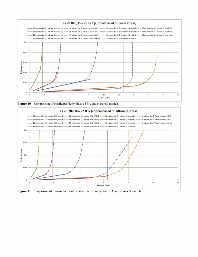
Figure 18: Posand the tin.
Figure 19: Pos
The tin eruptiohe thinner coa
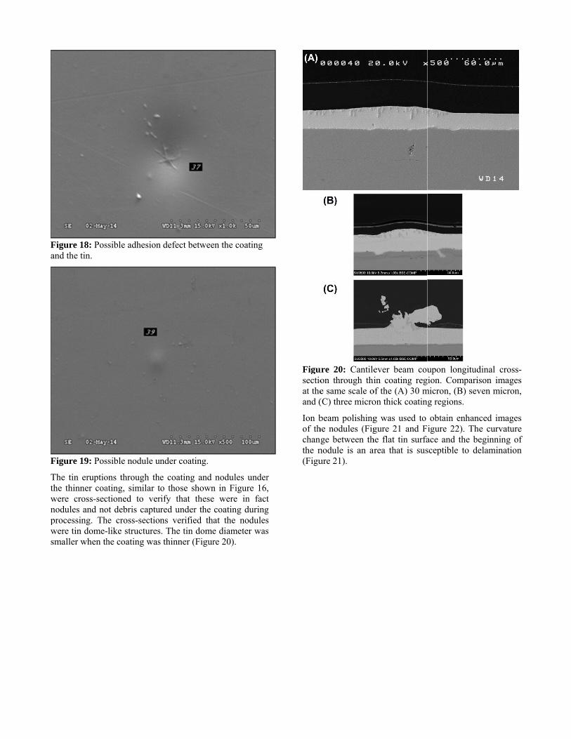
were cross-secnodules and noprocessing. Thwere tin dome-smaller when th
ssible adhesion
ssible nodule un
ons through theating, similar tctioned to verot debris captuhe cross-section-like structureshe coating was
n defect betwee
nder coating.
e coating and o those shown
rify that thesered under the ns verified tha
s. The tin domes thinner (Figur
en the coating
nodules undern in Figure 16,e were in factcoating duringat the nodulese diameter wasre 20).
r , t g s s
Figusectioat theand (
Ion bof thchangthe n(Figu
ure 20: Cantileon through thie same scale o(C) three micro
beam polishinghe nodules (Figge between th
nodule is an arure 21).
ever beam couin coating reg
of the (A) 30 mon thick coatin
g was used to gure 21 and F
he flat tin surfarea that is sus
upon longitudgion. Comparismicron, (B) sev
g regions.
obtain enhancigure 22). Theace and the besceptible to de
dinal cross-son images ven micron,
ced images e curvature eginning of elamination
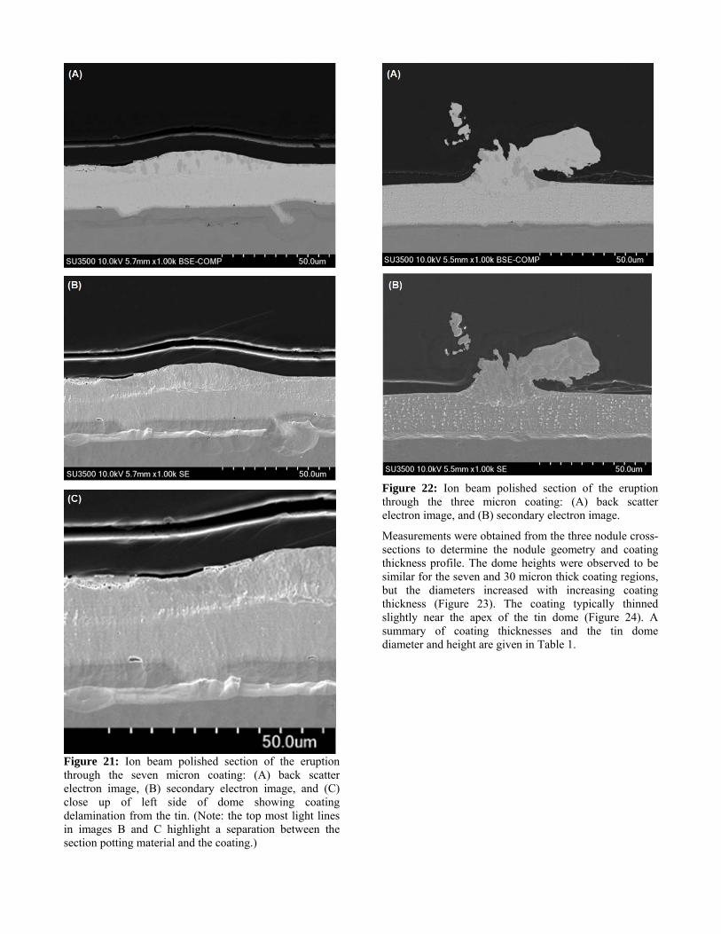
Figure 21: Ion beam polished section of the eruption through the seven micron coating: (A) back scatter electron image, (B) secondary electron image, and (C) close up of left side of dome showing coating delamination from the tin. (Note: the top most light lines in images B and C highlight a separation between the section potting material and the coating.)
Figure 22: Ion beam polished section of the eruption through the three micron coating: (A) back scatter electron image, and (B) secondary electron image.
Measurements were obtained from the three nodule cross-sections to determine the nodule geometry and coating thickness profile. The dome heights were observed to be similar for the seven and 30 micron thick coating regions, but the diameters increased with increasing coating thickness (Figure 23). The coating typically thinned slightly near the apex of the tin dome (Figure 24). A summary of coating thicknesses and the tin dome diameter and height are given in Table 1.

Fct
Fvsc
Ts
Figure 23: Mecoating thickneest sample.
Figure 24: Tyvalues across section measucoating shown.
Table 1: Coatsummary.
Nominal coating
thickness
Ac
th
(m
3 um
7 um
30 um
easured tin domess regions on
ypical measurethe sample. T
urements from
ting thickness
Average coating hickness
in flat region
microns)
Minco
thicat tdo
(mic
3.4 Rup
8.2 7
30.2 2
me height profithe cantilever
ed tin and coaThe second i
m the seven
and tin dome
nimum oating ckness top of ome crons)
Domdiame(micro
ptured 51.
7.1 79.
28.5 118
iles for variousbeam whisker
ating thicknesson beam millmicron thick
e measurement
me eter ons)
Domeheight
(micron
6 Rupture
5 6.8
8.5 5.7
s r
s l k
t
e t s)
ed
DISC
The nin thsoftetin ovuncomontcoupwhiskyear,increauthoto beof thover
In consiFigurpropeglassArath
Sincephenstruccoatinucleimpaimple
Figuslidethe inwere90°C
CUSSION
nucleation inhhe present worer Arathane 57ver brass under
oated areas [16ths of exposu
pons exhibited ker growth tha, the density eased rapidly aors also noted e on the verge ohe coating, with
time.
the present iderably more re 25 and Figuerties are redus transition temhane (Figure 2
e whisker grnomena causincture, it is reasing on the eation. Howevact the solderemented prope
ure 25: Nanoid. The as-receivinitial cure of e repeated afterC.
hibition observrk is in contras750, where nodr the coating w6]. The authoure at 50C,
four to five an the uncoate
of growth oand was simila
that a numberof breaking thrh the tin dome
experiments,rigid than the
ure 26. Althouuced at temperamperature, they7).
rowth is a sung formationsonable that thtin surface
ver, conformalr thermal cyerly [25][26].
dentation of Aved measurem6 hours at 85
r an additional
ed with the rigst to the behavdule nucleation
was much greators reported th
the coated sitimes more n
ed side. Howeon the non-coar to the coatedr of tin nodulerough the thinns developing s
, the coatine Arathane TM
ugh the PC18Matures above thy are still high
urface stress n of the tinhe presence ocould inhibi
l coating can ycling reliabili
Arathane 5750 ments were obt5 °C. The meal exposure of 1
gid coating vior of the n of bright ter than the hat at four ide of the nodule and ever after a oated side d side. The es appeared ner regions sharper tips
ngs were 5750 (see
M+XP2742 he PC18M er than the
relaxation n filament of the rigid it whisker negatively
ity if not
on a glass
tained after asurements 10 hours at

Figure 26: Nanoindentation testing results of PC18M filled with XP2742 (nanosilica); (A) elastic modulus, and (B) nanohardness.
Figure 27: Nanoindentation testing results of PC18M+20% XP2742 at room temperature, 50˚C, 85˚C, and 125˚C; (a) elastic modulus, and (b) nanohardness.
SUMMARY
The modeling showed reasonable correlation with the experimental whisker coupon results. The FEA modeling predicted rupture of a three micron thick coating which was consistent with the rigid coating experimental observations. Energy release rate results also indicate that delamination of a 100 micron coating thickness is unlikely for typical whisker diameters.
If the nodule/whisker diameter was larger, the coating needed to be thicker and/or stronger to provide mitigation. Subsequently whiskers could grow through the rupture site. In addition, the rupture area could have increased tin corrosion and/or electrical leakage.
CONCLUSIONS The following conclusions can be made
There is a combination of coating thickness, strength and adhesion that can provide whisker mitigation
In contrast to smaller diameter whiskers, larger diameter tin nodule formations have greater potential to rupture the coating
The whisker growth surface stress relaxation phenomena causing formation of the tin filament
structure is altered in the presence of a coating having high adhesion, high strength, and sufficient thickness
Although rigid coatings can inhibit tin nodule/whisker formation they need to be evaluated for potential impacts to solder joint thermal cycling fatigue reliability
FUTURE OPPORTUNITIES
Further tests to provide correlation between coating blister size, coating thickness and coating strength/modulus are recommended. In addition, coating deformation under the very slow strain rates associated with tin whisker growth needs to be understood further. Further work is also needed to rapidly and reliably determine the coating mechanical properties, critical adhesion energy between coatings and whisker prone metal surfaces. It would also be beneficial to have a better means to examine the nodule/whisker growth under the coating.
ACKNOWLEDGEMENTS
The authors wish to thank the Strategic Environmental Research and Development Program (SERDP) office for providing funding for this research.

REFERENCES [1] JP002, Current Tin Whiskers Theory and Mitigation
Practices Guideline, Joint JEDEC Solid State Technology Association/IPC Association Connecting Electronics Industries document, March 2006
[2] T. Shibutani, Q. Yu, M. Shiratori, M. Pecht, Pressure-induced tin whisker formation, Microelectronics Reliability Vol, 48 (2008) pp. 1033–1039
[3] G.T. Galyon, Annotated Tin Whisker Bibliography and Anthology, IEEE Trans. Packag. Manuf. Vol. 28, No. 1, January 2005, pp. 94-122.
[4] P. Snugovsky, S. Meschter, Z. Bagheri, E. Kosiba, M. Romansky, and J. Kennedy, Whisker Formation Induced by Component and Assembly Ionic Contamination, Journal of Electronic Materials, February 2012, Volume 41, Issue 2, pp 204-223 available for download at http://link.springer.com/content/pdf/10.1007%2Fs11664-011-1808-5.pdf
[5] S. Meschter, P. Snugovsky, Z. Bagheri, E. Kosiba, M. Romansky, J. Kennedy, L. Snugovsky, and D. Perovic, Whisker Formation on SAC305 Soldered Assemblies, JOM, vol. 66 no. 11, pp. 2320-2333, Nov. 2014 (DOI) 10.1007/s11837-014-1183-9
[6] S. Meschter, P. Snugovsky, J. Kennedy, Z. Bagheri, E. Kosiba, and A. Delhaise, SERDP Tin Whisker Testing and Modeling: High Temperature/High Humidity Conditions, SMTA International Conference on Soldering and Reliability, Toronto, Ontario, Canada; May 14-17, 2013.
[7] S. Meschter, E. Ekstrom, P. Snugovsky, .J. Kennedy, Z. Bagheri, and E. Kosiba, Strategic Environmental Research and Development Program (SERDP) Tin Whisker Testing and Modeling: Long Term Low Temperature High Humidity Testing, International Conference on Soldering and Reliability (ICSR 2015) Toronto, Ontario, Canada; May 19-21, 2015.
[8] B. Sood, M. Osterman and M. Pecht, Tin Whisker Analysis of Toyota's Electronic Throttle Controls, Circuit World, Vol. 37, No. 3, 2011, pp. 4–9
[9] GEIA-STD-0005-2, Standard for Mitigating the Effects of Tin Whiskers in Aerospace and High Performance Electronic Systems, SAE International, Warrendale, PA
[10] S. Han, S. Meschter, M. Osterman and M. Pecht, Evaluation of Effectiveness of Conformal Coatings as Tin Whisker Mitigation, Journal of Electronic Materials, DOI: 10.1007/s11664-012-2179-2, July 6, 2012.
[11] J. Cho, S. Meschter, S. Maganty, D. Starkey, M. Gomez, D. Edwards, A. Ekin, K. Elsken, J. Keeping, P. Snugovsky, and J. Kennedy, Characterization of Hybrid Conformal Coatings used for Mitigating Tin Whisker Growth, SMTA International Conference on Soldering and Reliability, Toronto, Ontario, Canada, May 14-17, 2013
[12] J. Cho, S. Meschter, S. Maganty, D. Starkey, M. Gomez, D. Edwards, A. Ekin, K. Elsken, J. Keeping, P. Snugovsky, J. Kennedy, and M. Romansky,
Polyurethane Conformal Coatings Filled with Hard Nanoparticles for Tin Whisker Mitigation, SMTA International Conference on Soldering and Reliability, Toronto, Ontario, Canada, May 13-15, 2014.
[13] D. Hillman, Tin Whiskers Inorganic Coating Evaluation, 7th International Symposium on Tin Whiskers, Nov. 12-13, 2013, Costa Mesa, CA
[14] L. Woody and W. Fox, Tin Whisker Risk Management by Conformal Coating, SMT magazine, July 2014, pp. 40-58.
[15] T. Woodrow, E. Ledbury, Evaluation of Conformal Coatings as a Tin Whisker Mitigation Strategy, Part 2, Proceedings of the SMTA International Conference, September 24-28, 2006.
[16] J. Kadesch, H. Leidecker, Effects of Conformal Coat on Tin Whisker Growth, Proceedings of IMAPS Nordic, The 37th IMAPS Nordic Annual Conference, pp. 108-116, September, 10-13, 2000
[17] L. Panashchenko, J. Brusse and H. Leidecker, Long Term Investigation of Urethane Conformal Coating Against Tin Whisker Growth Tenting of 2mil conformal coating, IPC Tin Whisker Conference Dec. 7, 2010
[18] S. Meschter, J. Cho, S. Maganty, D. Starkey, M. Gomez, D. Edwards, A. Ekin, K. Elsken, J. Keeping, P. Snugovsky, and J. Kennedy, Nanoparticle Enhanced Conformal Coating for Whisker Mitigation, SMTA International, Sept/Oct 2014
[19] M. Wickham, K. Clayton, C. Hunt, and B. Dunn, Sn whiskers and their mitigation for space, aerospace and defence electronics, EMPPS 5th Electronic Materials, Processes and Packaging for Space (EMPPS) Workshop, Noordwijk, NL, 20-22 May 2014
[20] D. Hillman IPC J-STD-001 Committee 522 AAR Conformal Coating Material & Application Industry Assessment, IPC Pb-Free Electronic Risk Management Council Meeting (PERM 25) and SAE G24 Lead-free Document Committee Meeting, Dayton (Beavercreek), OH, July 21-23, 2015
[21] M. Roma, S. Maganty, R. Roeder, J. Cho, S. Meschter; “Evaluation of Interfacial Adhesion of Polyurethane Conformal Coatings Used for Tin Whisker Mitigation”; Materials Science and Technology 2014 Conference and Exhibition, October 12-16, 2014 Pittsburgh, PA
[22] B.T. Han, C. Jang, K. Mahan, S. Han, M. Osterman, Long Term Reliability Evaluation of Conformal Coatings for Tin Whisker Failure Mitigation, University of Maryland, 2010.
[23] matweb.com; “Tin, Sn” [24] E. Volterra, and J, Gaines, Advanced Strength of
Materials; Prentice Hall, 1971 [25] G. Caswell, C. Tulkoff and N. Blattau, The Effect of
Coating and Potting on the Reliability of QFN Devices, DFR Solutions
[26] J. Wilcox, M. Meilunas and M. Anselm., Harsh Environment Reliability and Conformal Coat, SMTAi 2015
APPENDIX A: Nanoparticle enhanced polyurethane properties
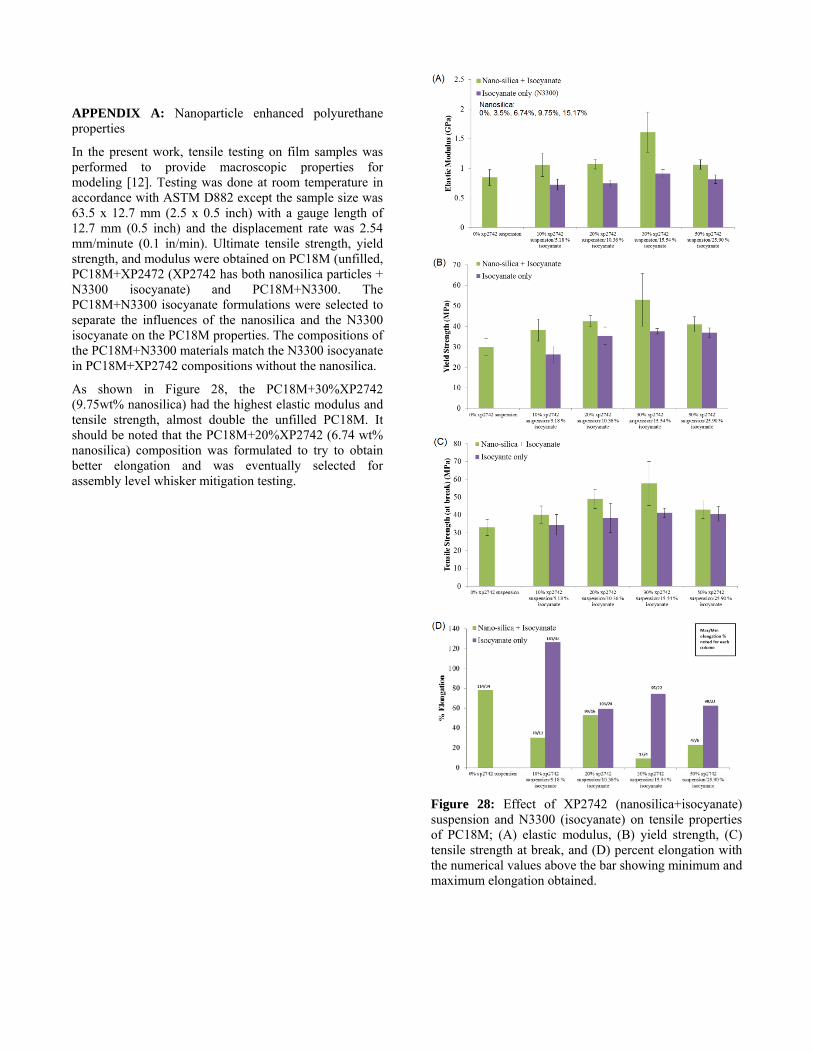
In the present work, tensile testing on film samples was performed to provide macroscopic properties for modeling [12]. Testing was done at room temperature in accordance with ASTM D882 except the sample size was 63.5 x 12.7 mm (2.5 x 0.5 inch) with a gauge length of 12.7 mm (0.5 inch) and the displacement rate was 2.54 mm/minute (0.1 in/min). Ultimate tensile strength, yield strength, and modulus were obtained on PC18M (unfilled, PC18M+XP2472 (XP2742 has both nanosilica particles + N3300 isocyanate) and PC18M+N3300. The PC18M+N3300 isocyanate formulations were selected to separate the influences of the nanosilica and the N3300 isocyanate on the PC18M properties. The compositions of the PC18M+N3300 materials match the N3300 isocyanate in PC18M+XP2742 compositions without the nanosilica.
As shown in Figure 28, the PC18M+30%XP2742 (9.75wt% nanosilica) had the highest elastic modulus and tensile strength, almost double the unfilled PC18M. It should be noted that the PC18M+20%XP2742 (6.74 wt% nanosilica) composition was formulated to try to obtain better elongation and was eventually selected for assembly level whisker mitigation testing.
Figure 28: Effect of XP2742 (nanosilica+isocyanate) suspension and N3300 (isocyanate) on tensile properties of PC18M; (A) elastic modulus, (B) yield strength, (C) tensile strength at break, and (D) percent elongation with the numerical values above the bar showing minimum and maximum elongation obtained.