Embed Size (px)
Citation preview
Strategies for Complete Expansion in I.C. Engine
P M V SubbaraoProfessor
Mechanical Engineering Department
Achieve Maximum Work Output….
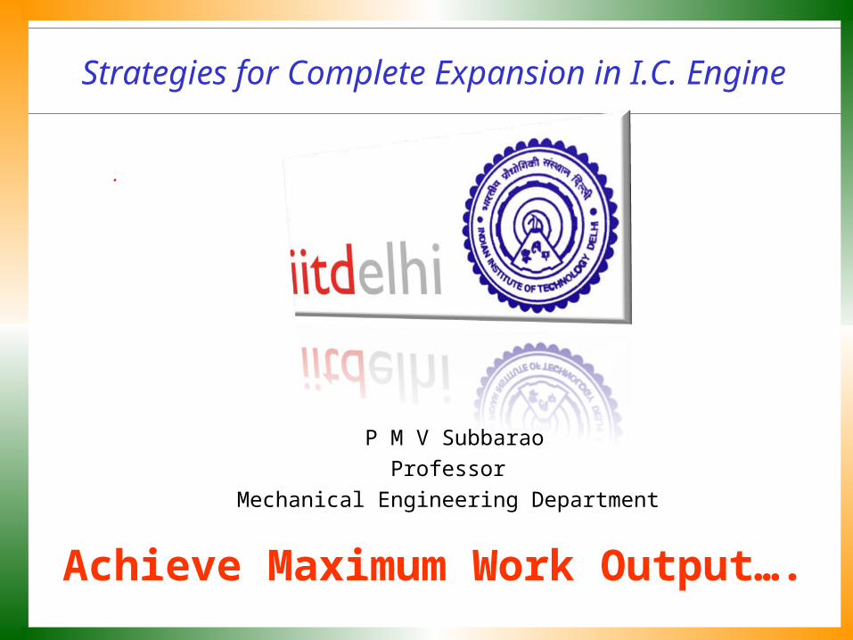
In 2000, a new engine is born ...
Three cylinder 5-Stroke engine
Five Stroke Internal Combustion Engine : A new concept for internal combustion enginesby Gerhard Schmitz, St.Vith 2011, Belgium
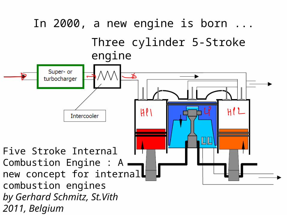
The Five Stroke Cycle
The five-stroke cycle consists in the following steps:
1. Admission in the high pressure (HP) cylinder
2. Compression, followed by the ignition
3. First expansion of the burned gases
4. Second expansion of the burned gases
5. Exhausting of the burned gases.

Phase A : Intake in Hp Cylinder 1, Expansion in HP 2 & Exhaust in LP
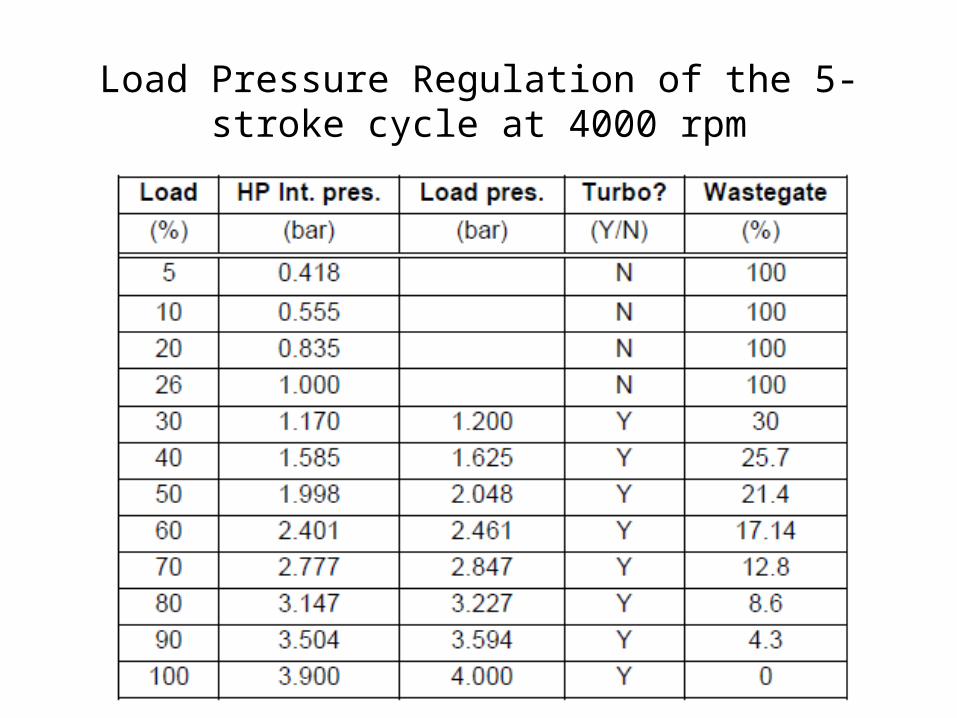
Load Pressure Regulation of the 5-stroke cycle at 4000 rpm

Speed Vs Loading Pressure @ Max. Torque

Phase B : Compression + Combustion in HP 1, Expansion in LP & Transfer from HP 2
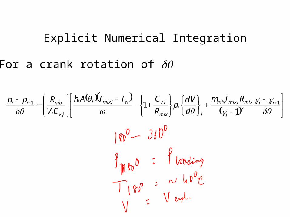
Explicit Numerical Integration
1
2,,,
,
1
11 ii
i
miximixmix
ii
mix
ivwimixii
ivi
mixiiRTm
d
dVp
R
CTTAh
CV
Rpp
For a crank rotation of
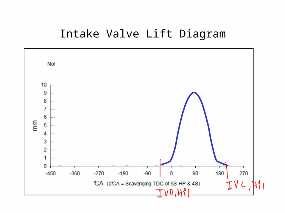
Intake Valve Lift Diagram
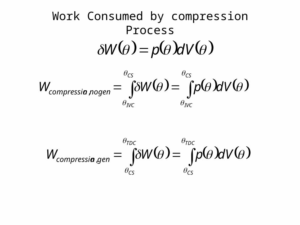
Work Consumed by compression Process
dVpW
CS
IVC
CS
IVC
dVpWW nogenncompressio
,
TDC
CS
TDC
CS
dVpWW genncompressio
,

d
dRTm
d
dVp
R
C
d
Q
d
Q
VC
R
d
dp mixmixmix
mix
vlossgen
v
mix21
1
In above Eq., the rate of the heat loss Qloss/dθ is expressed as:
wmixloss TThA
d
Q
The convective heat transfer coefficient is given by the Woschni model as 8.08.02.02.3 mixUpDh
Modeling of Combustion Process
coldIVCIVC
IVCmixdpmix pp
Vp
TVCsU ,
128.2
For combustion and expansion processes: C1=0.00324.
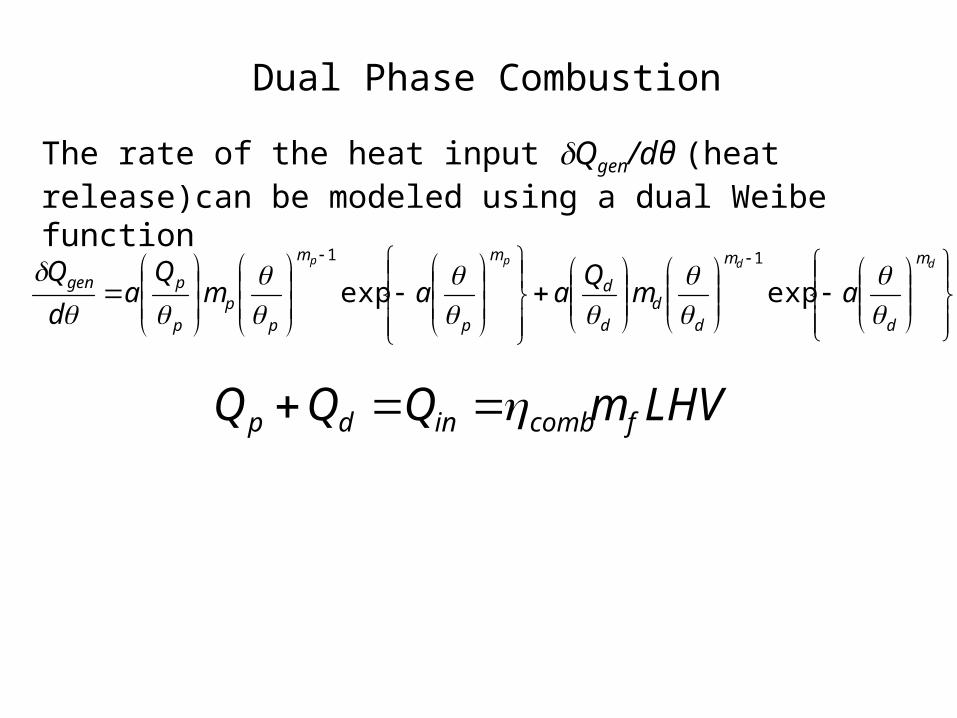
Dual Phase Combustion
LHVmQQQ fcombindp
ddpp m
d
m
dd
d
d
m
p
m
pp
p
pgen amQ
aamQ
ad
Q
expexp11
The rate of the heat input Qgen/dθ (heat release)can be modeled using a dual Weibe function
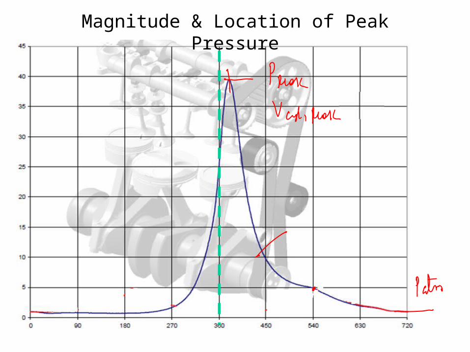
Magnitude & Location of Peak Pressure

Phase C : Combustion + Expansion in HP 1, Intake in HP2 & Exhaust from LP
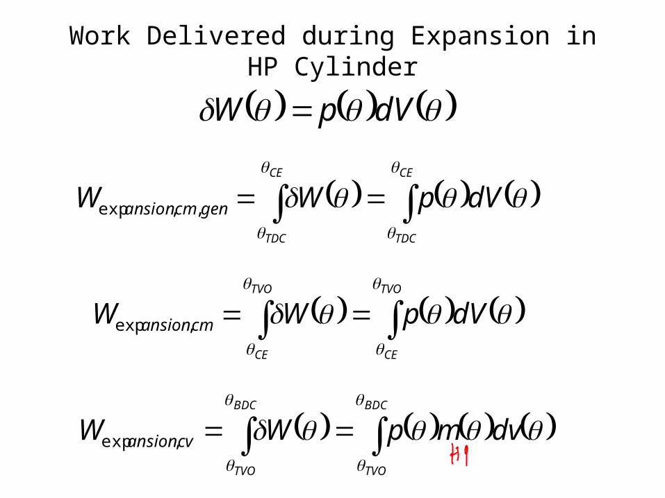
Work Delivered during Expansion in HP Cylinder
dVpW
TVO
CE
TVO
CE
dVpWW cmansion
,exp
BDC
TVO
BDC
TVO
dvmpWW cvansion
,exp
CE
TDC
CE
TDC
dVpWW gencmansion
,,exp

Phase D : Transfer from HP 1, Intake in HP 2 & Expansion in LP

Valve Lift Diagrams
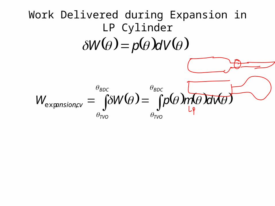
Work Delivered during Expansion in LP Cylinder
dVpW
BDC
TVO
BDC
TVO
dvmpWW cvansion
,exp
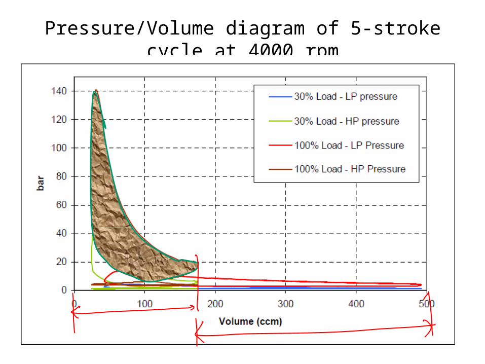
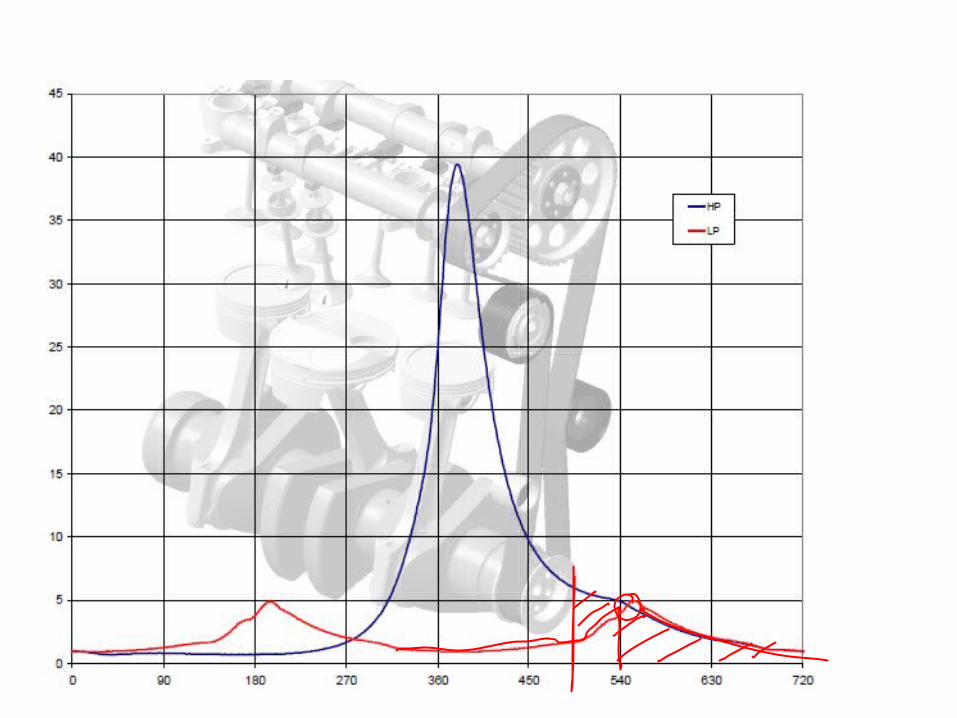
Pressure/Volume diagram of 5-stroke cycle at 4000 rpm
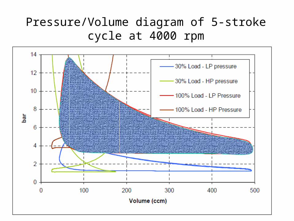
Pressure/Volume diagram of 5-stroke cycle at 4000 rpm
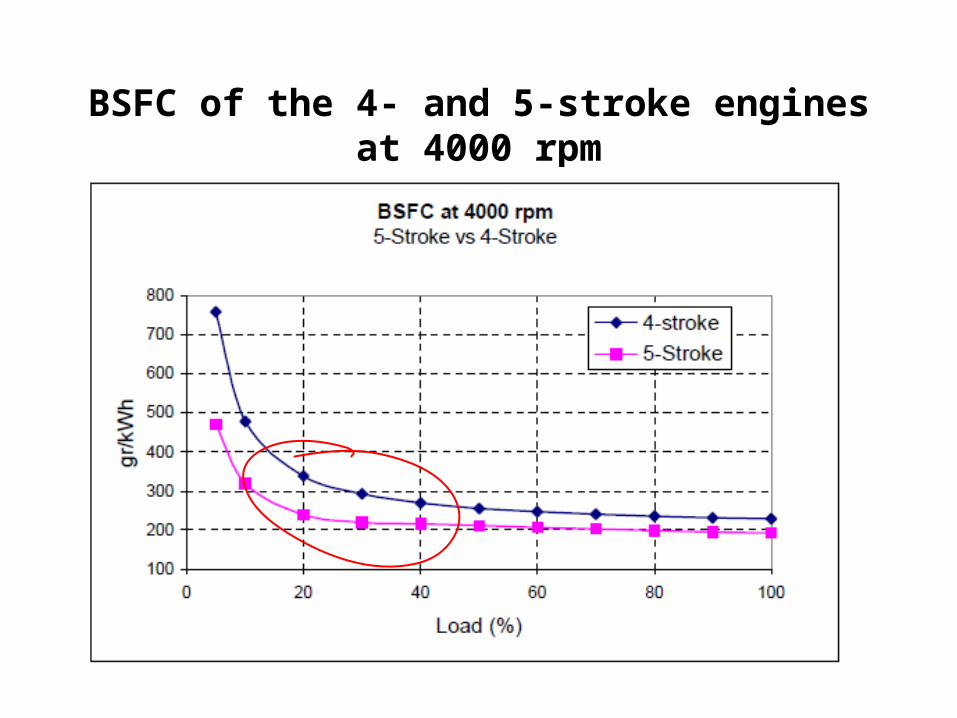
BSFC of the 4- and 5-stroke engines at 4000 rpm
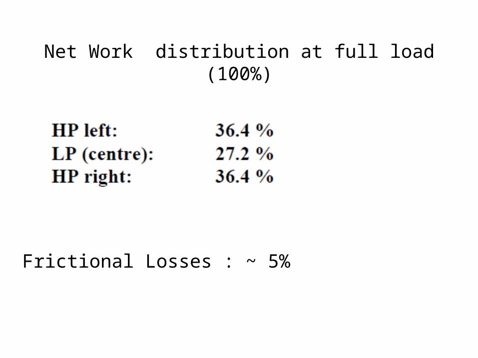
Net Work distribution at full load (100%)
Frictional Losses : ~ 5%