Embed Size (px)
Citation preview

HAL Id: hal-00144934https://hal.archives-ouvertes.fr/hal-00144934
Submitted on 7 May 2007
HAL is a multi-disciplinary open accessarchive for the deposit and dissemination of sci-entific research documents, whether they are pub-lished or not. The documents may come fromteaching and research institutions in France orabroad, or from public or private research centers.
L’archive ouverte pluridisciplinaire HAL, estdestinée au dépôt et à la diffusion de documentsscientifiques de niveau recherche, publiés ou non,émanant des établissements d’enseignement et derecherche français ou étrangers, des laboratoirespublics ou privés.
Strategies for the Design of a Slide-o-Cam TransmissionDamien Chablat, Jorge Angeles
To cite this version:Damien Chablat, Jorge Angeles. Strategies for the Design of a Slide-o-Cam Transmission. May 2005,Italy. pp.1-10. �hal-00144934�

hal-
0014
4934
, ver
sion
1 -
7 M
ay 2
007
Proceedings of CK2005, International Workshop on Computational Kinematics
Cassino May 4-6, 2005
paper xxCK2005
STRATEGIES FOR THE DESIGN
OF A SLIDE-O-CAM TRANSMISSION
D. Chablat1, J. Angeles2
1Institut de Recherche en Communications et Cybernetique de Nantes ∗
UMR CNRS n◦ 6597, 1 rue de la Noe, 44321 Nantes, France2Department of Mechanical Engineering &
Centre for Intelligent Machines, McGill University
817 Sherbrooke Street West, Montreal, Canada H3A 2K6
[email protected] [email protected]
Abstract
The optimization of the pressure angle in a cam-follower transmission is reported in this paper. This transmissionis based on Slide-o-Cam, a cam mechanism with multiple rollers mounted on a common translating follower.The design of Slide-o-Cam, a transmission intended to produce a sliding motion from a turning drive, or viceversa, was reported elsewhere. This transmission provides pure-rolling motion, thereby reducing the frictionof rack-and-pinions and linear drives. The pressure angle is a suitable performance index for this transmissionbecause it determines the amount of force transmitted to the load vs. that transmitted to the machine frame.Two alternative design strategies are studied, namely, (i) increase the number of lobes on each cam or (ii)increase the number of cams. This device is intended to replace the current ball-screws in Orthoglide, a three-DOF parallel robot for the production of translational motions, currently under development at Ecole Centrale
de Nantes for machining applications.
1 Introduction
In robotics and mechatronics applications, whereby motion is controlled using a piece of software, the conversionof motion from rotational to translational is usually done by either ball screws or linear actuators. Of thesealternatives, ball screws are gaining popularity, one of their drawbacks being the high number of moving partsthat they comprise, for their functioning relies on a number of balls rolling on grooves machined on a shaft; onemore drawback of ball screws is their low load-carrying capacity, stemming from the punctual form of contactby means of which loads are transmitted. Linear bearings solve these drawbacks to some extent, for they can befabricated with roller bearings; however, these devices rely on a form of direct-drive motor, which makes themexpensive to produce and to maintain.
A novel transmission, called Slide-o-Cam, was introduced in [1] as depicted in Fig. 1, to transform a rotationinto a translation. Slide-o-Cam is composed of four major elements: (i) the frame, (ii) the cam, (iii) the followerand (iv) the rollers. The input axis on which the cam is mounted, the camshaft, is driven at a time-varyingangular velocity, by an actuator under computer-control. Power is transmitted to the output, the translating
∗IRCCyN: UMR n◦ 6597 CNRS, Ecole Centrale de Nantes, Universite de Nantes, Ecole des Mines de Nantes

D. Chablat and J. Angeles to appear in WCK 2005 2
follower, which is the roller-carrying slider, by means of pure-rolling contact between cam and roller. The roller,in turn, comprises two components, the pin and the bearing. The bearing is mounted at one end of the pin,while the other end is press-fit into the roller-carrying slider. Contact between cam and roller thus takes place atthe outer surface of the bearing. The mechanism uses two conjugate cam-follower pairs, which alternately takeover the motion transmission to ensure a positive action; the rollers are thus driven by the cams throughout acomplete cycle. The main advantage of using a cam-follower mechanism instead of an alternative transmissionto transform rotation into translation is that contact through a roller reduces friction, contact stress and wear.
This transmission, once fully optimized, will replace the three ball screws used by the Orthoglide prototype[2]. Orthoglide features three prismatic joints mounted orthogonaly, three identical legs and a mobile platform,which moves in Cartesian space with fixed orientation, as shown in Fig. 2. The three motors are SANYODENKI (ref. P30B08075D) with a constant torque of 1.2 Nm from 0 to 3000 rpm. This property enables themechanism to move throughout the workspace a 4-kg load with an acceleration of 17 ms−2 and a velocity of1.3 ms−1. Furthermore, the pitch is 50 mm per cam turn, while the minimum radius of the camshaft is 8.5 mm.A new arrangement of camshaft, rollers and follower is proposed to reduce the inertial load when more thantwo cams are needed.
Roller
Follower
Conjugate cams
Figure 1: Layout of Slide-o-Cam Figure 2: The Orthoglide
Unlike Lampinen [3], who used a genetic algorithm, or Zhang and Shin [4], who used what they called “therelative-motion method,” where the relative velocity and acceleration of the the follower with respect to thecam is prescribed, we use a deterministic method that takes into account geometric and machining constraints[5].
The pressure angle µ (or its complement, the transmission angle) is a key performance index of cam-followertransmissions. One definition of pressure angle is the acute angle between the direction of the output force and
the direction of the velocity of the point where the output force is applied [6].Moreover, unlike Carra, Garziera and Pellegrini [7], who used a negative radius-follower to reduce the pressure
angle, we use a positive radius-follower that permits us to assemble several followers on the same roller-carrier.To optimize the pressure angle, two alternative design strategies are studied, namely, (i) increase the numberof lobes on each cam or (ii) increase the number of cams. The relations defined in [8] for cam profiles with onelobe are extended to several lobes.
2 Synthesis of the Planar Cam Mechanism
Let the x-y frame be fixed to the machine frame and the u-v frame be attached to the cam, as depicted in Fig. 3.O1 is the origin of both frames, while O2 is the center of the roller, and C is the contact point between cam androller. The geometric parameters defining the cam mechanism, with n lobes, are illustrated in the same figure.The notation of this figure is based on the general notation introduced in [9] and complemented in [8], namely,
• p, the pitch, i.e., the distance between the center of two rollers on the same side of the follower, insingle-lobed cams (distance is p/n in n-lobbed cams);
• n, the number of lobes;

D. Chablat and J. Angeles to appear in WCK 2005 3
• e, the distance between the axis of the cam and the line of centers of the rollers;
• a4, the radius of the roller bearing, i.e., the radius of the roller;
• ψ, the angle of rotation of the cam, the input of the mechanism;
• s, the displacement of the follower, given by the the position of the center of the roller, namely, the outputfunction of the mechanism;
• µ, the pressure angle;
• f , the force transmitted from cam to roller.
In our design, p is set to 50 mm, in order to meet the Orthoglide specifications.
O1
O2
O2
µ
C
f
x
y
e
su
v
a4
p/nψ
Figure 3: Parameterization of Slide-O-Cam
O1
O2
O2
Cx
y
s(0)
u
v
p/n
Figure 4: Home configuration of the mechanism, fora cam with four lobes
2.1 The Input-Output Function
The above parameters as well as the contact surface on the cam are determined by the geometric relationsdictated by the Aronhold-Kennedy Theorem in the plane [10]. When the cam makes a complete turn (∆ψ = 2π),the displacement of the roller is equal to p, i.e., the distance between n+1 rollers on the same side of the roller-carrying slider (∆s = p). Furthermore, if we consider the home configuration of the roller, as depicted inFig. 4, the roller is below the x-axis for ψ = 0, so that we have s(0) = −p/(2n). Hence, the expression for theinput-output function s is
s(ψ) =p
2πψ − p
2n(1)
The expressions for the first and second derivatives of s(ψ) with respect to ψ will be needed; these are readilyderived, namely,
s′(ψ) =p
2πand s′′(ψ) = 0 (2)
2.2 Cam-Profile Determination
The cam profile is determined by the displacement of the contact point C around the cam. This contact betweenone lobe and one roller takes place within 0 ≤ ψ ≤ 2π/n. For this domain we find the profile of one lobe. Theremaining n− 1 lobes are found by rotation around O1. The Cartesian coordinates of C in the u-v frame takethe form [9]
uc(ψ) = b2 cos(ψ) + (b3 − a4) cos(δ − ψ)
vc(ψ) = −b2 sin(ψ) + (b3 − a4) sin(δ − ψ)
D. Chablat and J. Angeles to appear in WCK 2005 4
with coefficients b2, b3 and δ given by
b2 = −s′(ψ) sinα1 (3a)
b3 =√
[e+ s′(ψ) sinα1]2 + [s(ψ) sinα1]2 (3b)
δ = arctan
( −s(ψ) sinα1
e+ s′(ψ) sinα1
)
(3c)
where α1 is the directed angle between the axis of the cam and the translating direction of the follower; α1 ispositive in the ccw direction. Considering the sign-convention adopted for the input angle ψ and for the outputs, as depicted in Fig. 3, we have
α1 = −π/2 (4)
We introduce now the non-dimensional design parameter η, which will be extensively used:
η =e
p(5)
Thus, from Eqs.(1), (2a), (3a–c), (4) and (5), we derive the expressions for coefficients b2, b3 and δ:
b2 =p
2π(6a)
b3 =p
2π
√
(2πη − 1)2 +(
ψ − π
n
)2
(6b)
δ = arctan
(
nψ − π
2nπη − n
)
(6c)
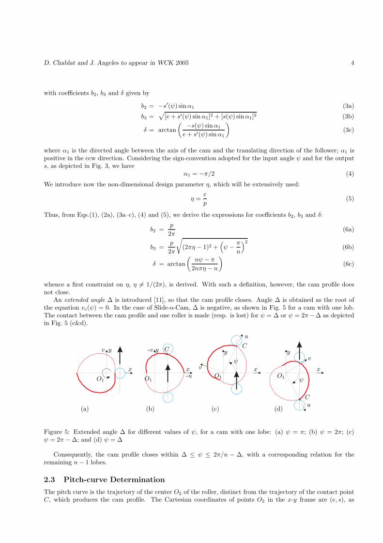
whence a first constraint on η, η 6= 1/(2π), is derived. With such a definition, however, the cam profile doesnot close.
An extended angle ∆ is introduced [11], so that the cam profile closes. Angle ∆ is obtained as the root ofthe equation vc(ψ) = 0. In the case of Slide-o-Cam, ∆ is negative, as shown in Fig. 5 for a cam with one lob.The contact between the cam profile and one roller is made (resp. is lost) for ψ = ∆ or ψ = 2π−∆ as depictedin Fig. 5 (c&d).
O1O1O1O1
xxxx
yyyy
u
u
v
v
v
C
CC
ψ
ψ
-u
-v
(a) (b) (c) (d)
Figure 5: Extended angle ∆ for different values of ψ, for a cam with one lobe: (a) ψ = π; (b) ψ = 2π; (c)ψ = 2π − ∆; and (d) ψ = ∆
Consequently, the cam profile closes within ∆ ≤ ψ ≤ 2π/n − ∆, with a corresponding relation for theremaining n− 1 lobes.
2.3 Pitch-curve Determination
The pitch curve is the trajectory of the center O2 of the roller, distinct from the trajectory of the contact pointC, which produces the cam profile. The Cartesian coordinates of points O2 in the x-y frame are (e, s), as

D. Chablat and J. Angeles to appear in WCK 2005 5
O1 O1O1 O1
x xx x
y yyy y
(a) (b) (c) (c)
Figure 6: Cam profile (in red) and pitch curve (in blue), within ∆ ≤ ψ ≤ 2π/n− ∆, with a4 = 4, p = 50 ande = 9, for: (a) n = 2; (b) n = 3; (c) n = 4; and (d) n = 5.
(a) (b)
O1O1
O2
O2
p/nxx
yy
ee
bb
B
a4
Figure 7: Constraints on the radius of the roller: (a) a4 < p/(2n); and (b) a4 ≤ ηp− b.
depicted in Fig. 3. Hence, the Cartesian coordinates of the pitch curve in the u-v frame are
up(ψ) = e cos(ψ) + s(ψ) sin(ψ) (7a)
vp(ψ) = −e sin(ψ) + s(ψ) cos(ψ) (7b)
Figure 6 shows a plot of the cam profile and its pitch curve, within ∆ ≤ ψ ≤ 2π/n−∆, throughout all n lobes.
2.4 Geometric Constraints on the Mechanism
In order to lead to a feasible mechanism, the radius a4 of the roller must satisfy two conditions, as shown inFig. 7:
• Two consecutive rollers on the same side of the roller-carrying slider must not interfere with each other.Since p/n is the distance between the center of two consecutive rollers, we have the constraint 2a4 < p/n.Hence the first condition on a4:
a4 <p
2n(8)
• The radius b of the shaft on which the cams are mounted must be taken into consideration. Hence, wehave the constraint a4 + b ≤ e , the second constraint on a4 in terms of the parameter η thus being1
a4 ≤ ηp− b (9)
Considering the initial configuration of the roller, as depicted in Fig. 4, the v-component of the Cartesiancoordinate of the contact point C is negative in this configuration, i.e., vc(0) ≤ 0. However, from the expression
1It is possible to have a4 = ηp− b if the cams and the shaft are machined from the same block. Thus, there is a common point,referred to as B in Fig. 7b, between the shaft and the cam profile. This will not be the solution chosen for our design, because itis too complicated to machine the cams and the shaft on the same block.

D. Chablat and J. Angeles to appear in WCK 2005 6
for vc(ψ) and for parameters b3 and δ given in Eqs. (6b & c), respectively, the above relation leads to thecondition:
( p
2πn
√
(2nπη − n)2 + π2 − a4
)
sin
[
arctan
( −π2nπη − n
)]
≤ 0 (10)
Further, we define parameters A and B as
A =p
2nπ
√
(2nπη − n)2 + π2 − a4 and B = sin
[
arctan
( −π2nπη − n
)]
(11)
Now we derive a constraint A. Since (2πnη − n)2 > 0, we have
√
(2nπη − n)2 + π2 > π
Hence,
A >p
2n− a4
Furthermore, from the constraint on a4 established in Eq. (8), we have p/(2n) − a4 > 0, whence A > 0.Consequently, the constraint vc(0) ≤ 0 leads to the constraint B ≤ 0.
We transform now the expression for B by using the trigonometric relation:
∀x ∈ R, sin(arctanx) =x√
1 + x2
Hence, the constraint vc(0) ≤ 0 becomes
−πn(2πη − 1)
√
1 + π2/(2nπη − n)2≤ 0
which holds only if 2πη − 1 > 0. Finally, the constraint vc(0) ≤ 0 leads to a constraint on η, namely2,
η >1
2π(12)
Equations 8, 9 and 12 permit us to reduce the design parameter space. Figure 8 depicts the design parameterspace for P = 50mm and b = 4.25mm. We can notice that when the number of lobes by cam increases, themaximum value of a4 decreases.
25
20
15
10
5
1/(2π)1/π
0.45 1 2 3 4
a4
η
nfeasible domain
Figure 8: Design parameter space for P = 50mm and b = 4.25mm
2If in the initial configuration the roller were on the upper side of the x-axis, the input-output function would be s(ψ) =(p/2π)ψ + p/2, and we would have the constraint vc(0) ≥ 0, which would lead to the same constraint η > 1/(2π).

D. Chablat and J. Angeles to appear in WCK 2005 7
2.5 Pressure Angle
The pressure angle of cam-roller-follower mechanisms is defined as the angle between the common normal atthe cam-roller contact point C and the velocity of C as a point of the follower [12], as depicted in Fig. 3, wherethe pressure angle is denoted by µ. This angle plays an important role in cam design. The smaller |µ|, thebetter the force transmission. In the case of high-speed operations, i.e., angular velocities of cams exceeding50 rpm, the pressure-angle is recommended to lie within 30◦.
For the case at hand, the expression for the pressure-angle µ is given in [12] as
tanµ =s′(ψ) − e
s(ψ)
Considering the expressions for s and s′, and using the parameter η given in Eqs.(1), (2a) and (6), respectively,the expression for the pressure angle becomes
tanµ =n− 2nπη
nψ − π
2.6 Conjugate Cams
To reduce the pressure angle, several cams can be assembled in the same cam-shaft. We note m the number ofcams and β the angle of rotation between two adjacent cams, i.e.,
β =2π
nm
On the Slide-o-Cam mechanism first designed in [1], two conjugate cams with one lobe each and β = π wereused. Figure 9 shows two cam profiles with one and two lobes.
O1 O1x x
y
yy
-5-5
-10
-10
-10
-10
-15
-15
-20
-20
-30 5
5
10
10
10
10
15
15
20
20
30
(a) (b)
Figure 9: Assembly of two cams with p = 50, a4 = 10 and e = 9: (a) one lobe; (b) two lobes
2.7 Convexity of the Cam Profile
The convexity of the cam influences the accuracy of the machining; for this reason it is preferable to have aconvex cam profile for each part of the cam where it drives the roller. In this section, we establish conditions onthe design parameters η and a4 in order to have such a property. We will thus study the sign of the curvatureof the cam profile via that of the pitch curve.
The curvature of any planar parametric curve, in terms of the Cartesian coordinates u and v, and parame-terized with any parameter ψ, is given in [12],
κ =v′(ψ)u′′(ψ) − u′(ψ)v′′(ψ)
[u′(ψ)2 + v′(ψ)2]3/2(13)
The sign of κ in Eq.(13) tells whether the curve is convex or concave at a point: a positive κ implies a convexity,while a negative κ implies a concavity at that point. The computation of the first and second derivatives of the

D. Chablat and J. Angeles to appear in WCK 2005 8
Cartesian coordinates of the pitch curve, defined in Eqs. (7), with respect to the angle of rotation of the cam,ψ, are
u′p(ψ) = ( s′(ψ) − e) sin(ψ) + s(ψ) cos(ψ) (14a)
v′p(ψ) = ( s′(ψ) − e) cos(ψ) − s(ψ) sin(ψ) (14b)
u′′p(ψ) = (2s′(ψ) − e) cos(ψ) − s(ψ) sin(ψ) (14c)
v′′p (ψ) = −(2s′(ψ) − e) sin(ψ) − s(ψ) cos(ψ) (14d)
By substituting η = e/p, with Eqs.(14a-d) into Eq.(13), the curvature κp of the pitch curve can be obtained as
κp = −2n2π
p
[(nψ − π)2 + 2n2(2πη − 1)(πη − 1)]
[(nψ − π)2 + n2(2πη − 1)2]3/2(15)
provided that the denominator never vanishes for any value of ψ, i.e., if we observe the condition:
η 6= 1/(2π)
Considering the expression for κp in Eq.(15), we have, for every value of ψ,
κp ≥ 0 if (2πη − 1)(πη − 1) ≥ 0 and η 6= 1
2π
whence the condition on η:
κp ≥ 0 if η ∈ [0,1
2π[∪[
1
π,+∞[ (16)
The condition on η given in Eq.(16) must be combined with the condition established in Eq.(12), η > 1/(2π).Hence, the final convexity condition of the pitch curve is:
η ≥ 1
π(17)
3 Influence of the Number of Conjugate Cams and the Number of
Lobes on the Pressure Angle
3.1 Active Angular Interval of the Pressure Angle
We are only interested in the interval of ψ where the cam drives the roller to go to the right; we call this theactive interval. An other interval of ψ exists, with the same range, when the cam drives the roller to go to theleft as is depicted in Fig. 10.
• A single-cam mechanism: The active interval is:
π
n≤ ψ ≤ 2π
n− ∆
Indeed, if we start the motion in the home configuration depicted in Fig. 4, with the cam rotating in the ccwdirection, the cam begins to drive the roller only when ψ = π/n; the cam can drive the follower until contactis lost, i.e., when ψ = 2π/n − ∆, as shown in Fig. 5c. With only one cam, the cam cannot drive the rollerthroughout one complete turn, as depicted in Fig. 10. This result holds for all values of n. Thus, a cam-followerassembly must have a least two conjugate cams. When −π/n+δ ≤ ψ ≤ 2π/n−δ, contact between two followersand the cam occurs.

D. Chablat and J. Angeles to appear in WCK 2005 9
µ (degree)
ψ(rad)−π π 2π12108642-2-4-6
-20
-40
-60
-80
20
40
60
80the came pushes
the came pushes
to the left
to the rightπ − ∆ 2π − ∆
Figure 10: Pressure-angle distribution for one cam with one lobe, with p = 50, a4 = 10 and e = 9
• A two-conjugate-cam mechanism: The active interval is:
π
n− ∆ ≤ ψ ≤ 2π
n− ∆
Indeed, the conjugate cam can also drive the follower when 0 ≤ ψ ≤ π/n − ∆; there is, therefore, a commoninterval, for π/n ≤ ψ ≤ π/n− ∆, during which two cams can drive the follower. In this interval, the conjugatecam can drive a roller with lower absolute values of the pressure angle. We assume that, when the two cams drivethe rollers, the cam with the lower absolute value of pressure angle effectively drives the follower. Consequently,we are only interested in the value of the pressure angle in the interval π/n− ∆ ≤ ψ ≤ 2π/n− ∆, as depictedin Fig. 11.
• A three-conjugate-cam mechanism: For the same reason, the active interval is:
4π
3n− ∆ ≤ ψ ≤ 2π
n− ∆
This interval is 33% smaller than a two-conjuage-cam-mechanism, the part of the interval removed having thehighest pressure angle, as depicted in Fig. 12.
µ (degree) µ (degree)
ψ(rad) ψ(rad)
1210 108 86 64 42 2-2 -2-4 -4-6 -6-20 -20
-40 -40
-60 -60
-80 -80
20 20
40 40
60 60
80 80the came pushes
the came pushes
the came pushes
the came pushes
to the left to the left
to the right to the right
(a) (b)
Figure 11: Pressure-angle distribution for two conjugate-cams with (a) one lobe and (b) two lobes, with p = 50,a4 = 10 and e = 9

D. Chablat and J. Angeles to appear in WCK 2005 10
µ (degree)
ψ(rad)
105-5-20
-40
-60
-80
20
40
60
80the came pushes
the came pushes
to the left
to the right
Figure 12: Pressure-angle distribution for three conjugate-cams with one lobe, p = 50, a4 = 10 and e = 9
3.2 Pressure Angle and Design Parameters
We study here the influence of design parameters η, a4 and n on the values of the pressure angle, whith thecam driving the roller, as reported in [13]. We also study the influence of the number of conjugate cams on thevalue of pressure angle.
• Influence of parameter η
Figure 13 shows the influence of the parameter η on the pressure angle, with a4 and p being fixed for severalnumbers of cams and lobes. From these plots we have the result:
The lower η, the lower the absolute value of the pressure angle, with η ≥ 1/π, as defined in Eq.17.
This result is the same if we consider a single cam with several lobes or a two- or three-conjugate-cam mechanism.
• Influence of the radius of the roller a4
Parameter a4 does not appear in the expression for the pressure angle, but it influences the value of the extendedangle ∆, and hence the plot boundaries of the pressure angle, as shown in Fig. 14 for two value of a4.
By computing the value of the extended angle ∆ for several values of a4, we notice that the higher a4, thelower the absolute value of ∆. Consequently, since the boundaries to plot the pressure angle for a system withtwo conjugate cams are π/n−∆ and 2π/n−∆ or 4π/3n−∆ and 2π/n−∆ for three conjugate cams, we noticethat when we increase a4, −∆ decreases or, equivalently, ∆ increases and the boundaries are translated towardthe left, i.e., toward higher absolute values of the pressure angle. We thus have the result:
The lower a4, the lower the absolute value of the pressure angle.
This result is valid for single or conjugate-cam mechanisms and is independent of the number of lobes.
• Influence of the number of lobes n
By computing the value of the pressure angle for several values of n, as depicted in Fig. 13, we have the result:
The lower n, the lower the absolute value of the pressure angle.
For at least two lobes, contact is lost when the pressure angle is greater than 20◦.
• Influence of the Number of Conjugate Cams
Figures 11(a) and 12 show that the higher the number of cams, the lower the active interval. Especially, thenumber of cams reduces the maximum absolute value of the pressure angle. Therefore,
The higher the number of conjugate cams, the lower the absolute value of the pressure angle.

D. Chablat and J. Angeles to appear in WCK 2005 11
µ (degree)µ (degree)
µ (degree)µ (degree)
ψ(rad)ψ(rad)
ψ(rad) ψ(rad)
η = 5η = 5
η = 5η = 5
η = 2η = 2
η = 2η = 2
η = 1.5η = 1.5
η = 1.5η = 1.5
η = 1η = 1
η = 1η = 1
η = 0.8η = 0.8
η = 0.8η = 0.8
η = 0.4η = 0.4
η = 0.4η = 0.4
η = 1/πη = 1/π
η = 1/πη = 1/π
88 77 66 55
4
44
4 33
33
2 211
00
0 0
-20-20
-20 -20
-40-40
-40 -40
-60-60
-60 -60
-80-80
-80 -80
(a) (b)
(c) (d)
Figure 13: Influence of parameter η on the pressure angle µ (in degree), with p = 50 mm and a4 = 10 mm, forone or two lobes and one or two cams, for (a) one cam and one lobe; (b) two cams and one lobe; (c) one camand two lobes; and (d) two cams and two lobes
µ (degree) µ (degree)
ψ(rad) ψ(rad)
η = 5 η = 5η = 2 η = 2η = 1.5 η = 1.5η = 1 η = 1η = 0.8 η = 0.8
η = 0.4 η = 0.4η = 1/π η = 1/π
8 87 76 65 54 40 0
-20 -20
-40 -40
-60 -60
-80 -80
(a) (b)
Figure 14: Influence of parameter a4 on the pressure angle µ (in degree), for one lobe and two cams, withp = 50 mm and (a) a4 = 10 mm and (b) a4 = 25 mm

D. Chablat and J. Angeles to appear in WCK 2005 12
4 Conclusions
Two design strategies have been used in this paper to reduce the pressure angle in the Slide-o-Cam mechanism.The optimum solution is found whenever (i) the number of lobes is one, (ii) for the higher number of conjugatecams, (iii) for the smallest value of the radius of the roller a4 and (iv) for the smallest value of η. However,to minimize the deformation of the roller pin, a4 have to be computed to resist to efforts during the motionas is made in [8]. Further research is currently underway to evaluate the influence of variations in the designparameters on the pressure angle and the active interval and the design of cam with non-convex shape.
References
[1] Gonzalez-Palacios, M.A. and Angeles, J., 2003, The design of a novel pure-rolling transmission to convertrotational into translational motion”, Journal of Mechanical Design, Vol. 125, pp. 205–207
[2] Chablat, D. and Wenger Ph., 2003, “Architecture Optimization of a 3-DOF Parallel Mechanism for Machin-ing Applications, the Orthoglide,” IEEE Transactions on Robotics and Automation, Vol. 19/3, pp. 403–410,June.
[3] Lampinen, J. 2003, “Cam shape optimisation by genetic algorithm,” Computer-Aided Design, Vol. 35,pp. 727-737.
[4] Zhang, Y. and Shin, J.-H., 2004, “A Computational Approach to Profile Generation of Planar Cam Mech-anisms,” Journal of Mechanical Design, Vol. 126-1, pp. 183–188.
[5] Bouzakis, K.D., Mitsi, S. and Tsiafis, J., 1997, “Computer-Aided Optimum Design and NC Milling ofPlanar Cam Mechanims,” Int. J. Math. Tools Manufact. Vol. 37, No. 8, pp. 1131–1142.
[6] Shigley, J.E., Uicker, J.J., 1980, “Theory of Machines and Mechanisms,” McGraw-Hill, New York, 1980.
[7] Carra, S., Garziera, R. and Pellegrini, M., 2004, “Synthesis of cams with negative radius follower andevaluation of the pressure angles,” Mechanism and Machine Theory, Vol. 34, pp. 1017–1032.
[8] Renotte J., Chablat D. and Angeles J., 2004, “The Design of a Novel Prismatic Drive for a Three-DOFParallel-Kinematics Machine,” ASME Design Engineering Technical Conferences, September-October 28-2,Salt Lake City, Utah, USA.
[9] Gonzalez-Palacios, M. A. and Angeles, J., 1993, Cam Synthesis, Kluwer Academic Publishers B.V., Dor-drecht.
[10] Waldron, K. J. and Kinzel, G. L., 1999, Kinematics, Dynamics, and Design of Machinery, John Wiley &Sons, Inc., New York.
[11] Lee, M.K., 2001, Design for Manufacturability of Speed-Reduction Cam Mechanisms, M.Eng. Thesis, Dept.of Mechanical Engineering, McGill University, Montreal.
[12] Angeles, J. and Lopez-Cajun,C., 1991, Optimization of Cam Mechanisms, Kluwer Academic PublishersB.V., Dordrecht.
[13] Zhang W. and Angeles, J. 2004, “A parametric study of planar cam-roller speed reducers,” Transactions
of the Canadian Society for Mechanical Engineering, Vol. 28, No. 2A, pp. 263–275.