Embed Size (px)
Citation preview

STRATEGY AND PLANNING COMMITTEE AGENDA
TUESDAY 17 JUNE 2014
AT 1PM
IN COMMITTEE ROOM 1, CIVIC OFFICES, 53 HEREFORD STREET Committee: Councillor Jamie Gough (Chairperson)
Councillors Paul Londsdale (Deputy Chairperson), Jimmy Chen, David East, Raf Manji, Andrew Turner and Vicki Buck
Principal Adviser Committee Adviser Mike Theelen Telephone: 941-8281
Lucy Halsall Telephone: 941-6227
PART A - MATTERS REQUIRING A COUNCIL DECISION PART B - REPORTS FOR INFORMATION PART C - DELEGATED DECISIONS INDEX ITEM NO.
DESCRIPTION PAGE NO.
PART C 1. APOLOGIES 1 PART B 2. DECLARATION OF INTEREST 1 PART B 3. DEPUTATIONS BY APPOINTMENT 1 PART B 4. CENTRAL CITY RECOVERY QUARTERLY MEMO – JANUARY TO MARCH 2014 3 PART A 5. POLICY ON STRUCTURES ON ROAD AMENDMENT TO ACCOMMODATE BASE
ISOLATION FOUNDATIONS ON PUBLIC ROAD LAND 11


STRATEGY AND PLANNING COMMITTEE 17. 6. 2014
1. APOLOGIES 2. DECLARATION OF INTEREST
Members are reminded of the need to be vigilant to stand aside from decision making when a conflict arises between their role as a member and any private or other external interest they might have.
3. DEPUTATIONS BY APPOINTMENT
1

2

STRATEGY AND PLANNING COMMITTEE 17. 6. 2014
4. CENTRAL CITY RECOVERY QUARTERLY MEMO – JANUARY TO MARCH 2014 Contact Contact Details
General Manager responsible: General Manager Strategy and Planning
Officer responsible: Urban Design and Regeneration Unit Manager
Y Carolyn Ingles, 03 941 8239
1. PURPOSE OF MEMO
1.1 The purpose of this memo is to update the Strategy and Planning Committee on the implementation of central city recovery projects for the period January 2014 to March 2014, with additional updates for some activities to May 2014.
1.2 Quarterly updates are provided for central city recovery activities. This report is the third
for the 2013-14 financial year. The key activities reported on are:
resource consents transitional city activity Transitional City Projects Fund Creative Industries Support Fund Christchurch Central Recovery Plan anchor projects enabling central city recovery support for other organisations that lead transitional projects communications and marketing
1.3 Photos of several projects are included at the end of this report as Attachment 1.
2. RESOURCE CONSENTS
2.1 Table 1 sets out the resource consent applications received during the months of January to March 2014 for the central city. Note some consents are for minor works to existing buildings or changes to consent conditions. This information is more specific than that provided in the consenting rebuilding monthly reports. When compared to the last quarter for 2013 where a total of 68 resource consent applications were received for the central city, the overall figures for this quarter have dropped by just under 50 per cent. It is quite typical to experience an increase in application numbers during November and December and a reduction in the number of applications received during the January period.
Table 1: Resource Consent Activity
Consent Type Number Land Use Consents within Four Avenues
(excluding Core) 27
Land Use Consents within Core 8 Existing Use Certificates 0 TOTAL 35
2.2 During the last quarter resource consents were approved in the Central City Business
Core by the Joint Management Board (JMB) for a three level office building and café at the corner of Cashel and Montreal Streets, a new two level mixed used building opposite the Triangle Centre car park and a five storey office building at 213 – 221 Tuam Street.
2.3 Resource consents were also approved for a 24 unit apartment building on Bealey
Avenue and 43 residential units and a café at the corner of Madras and Armagh Streets.
2.4 During the second quarter of this year resource consent was also approved by the JMB for a seven storey commercial building at 164 Hereford Street adjacent to Tattersails Lane.
3

STRATEGY AND PLANNING COMMITTEE 17. 6. 2014
4 Cont’d 3. TRANSITIONAL CITY ACTIVITY
3.1 The Council’s transitional city programme aims to support central city regeneration through improving amenity, attracting people to the central city, and increasing community participation and engagement in the recovery through temporary and cost effective projects. The programme is divided into public space projects led or facilitated by the Council, and support for community and private-sector initiatives on vacant sites not already managed as public spaces. A Cathedral Square Coordination Group of council officers meets monthly to coordinate events, transitional projects, maintenance and integration with neighbouring land use activities in the Square.
3.2 Table 2 provides a summary of progress with public space Council-led transitional
projects in the central city.
Table 2: Transitional (Temporary) Streetscape projects
PROJECT UPDATE SINCE SEPTEMBER REPORT COMPONENTS
Cathedral Square
The temporary iSite has been removed from the square for winter. It is likely to return in Oct 2014 for the tourist season.
The Flag Wall installation was completed in March 2014. Very good media coverage at time of install, and it is popular with visitors to the square.
The Whare will continue to be refreshed with new plants. This will be undertaken in partnership with Council’s Botanic Gardens team.
The fence wraps have been refreshed after damage by storm events. The fences have been further stabilised with concrete lock-blocks.
The chess set has been repaired by the Events Team and is available for public use.
Flag Wall installed Fencewraps refreshed Fenceline to be
stabilised with concrete lock-blocks.
Whare planting to be
maintained regularly
Way finding
Central city pedestrian signage (way-finding plinths) continues to be reviewed and updated as necessary especially as new areas and attractions open up in the central city.
Updating signs progressively with changes
Worcester Street
Work is progressing on the Worcester Street transitional project as part of the 2013/14 transitional programme. Concepts were approved in March and the project is working through design review process, ready for implementation in June. This project will enhance the pedestrian environment and amenity, with the use of solar components as a way to assist with way-finding.
Refresh floral planters on Worcester Street bridge
Reinstate street trees and install new planters with trees
Footpath and rubbish bin repairs
Build out kerbs New innovative solar
bollards and solar pavers
Two new way-finding plinths
4
STRATEGY AND PLANNING COMMITTEE 17. 6. 2014
4 Cont’d
Solar charge table
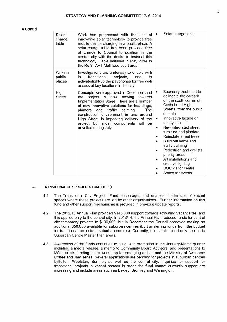
Work has progressed with the use of innovative solar technology to provide free mobile device charging in a public place. A solar charge table has been provided free of charge to Council to position in the central city with the desire to test/trial this technology. Table installed in May 2014 in the Re:START Mall food court area.
Solar charge table
Wi-Fi in public places
Investigations are underway to enable wi-fi in transitional projects, and to activate/light-up the payphones for free wi-fi access at key locations in the city.
High Street
Concepts were approved in December and the project is now moving towards Implementation Stage. There are a number of new innovative solutions for hoardings, planters and traffic calming. The construction environment in and around High Street is impacting delivery of the project but most components will be unveiled during July.
Boundary treatment to delineate the carpark on the south corner of Cashel and High Streets, from the public domain
Innovative façade on empty site
New integrated street furniture and planters
Reinstate street trees Build out kerbs and
traffic calming Pedestrian and cyclists
priority areas Art installations and
creative lighting DOC visitor centre Space for events
4. TRANSITIONAL CITY PROJECTS FUND (TCPF)
4.1 The Transitional City Projects Fund encourages and enables interim use of vacant
spaces where these projects are led by other organisations. Further information on this fund and other support mechanisms is provided in previous update reports.
4.2 The 2012/13 Annual Plan provided $145,000 support towards activating vacant sites, and
this applied only to the central city. In 2013/14, the Annual Plan reduced funds for central city temporary projects to $100,000, but in December the Council approved making an additional $50,000 available for suburban centres (by transferring funds from the budget for transitional projects in suburban centres). Currently, this smaller fund only applies to Suburban Centre Master Plan areas.
4.3 Awareness of the funds continues to build, with promotion in the January-March quarter
including a media release, a memo to Community Board Advisors, and presentations to Māori artists funding hui, a workshop for emerging artists, and the Ministry of Awesome Coffee and Jam series. Several applications are pending for projects in suburban centres Lyttelton, Woolston, Sumner, as well as the central city. Inquiries for support for transitional projects in vacant spaces in areas the fund cannot currently support are increasing and include areas such as Bexley, Bromley and Warrington.
5

STRATEGY AND PLANNING COMMITTEE 17. 6. 2014
4 Cont’d
Table 3: TCPF summary of funded applicants for the January-March 2014 Period
APPLICANT
LEGAL ENTITY
PROJECT AMOUNT REQUESTED
AMOUNT FUNDED (CENTRAL CITY)
Trudy Lane and Halsey Burgund
Sound Sky – to curate and crowd-source audio activation of vacant sites and create GPS-triggered soundwalks that can be accessed online and via smartphones.
$14,850 $7,000
Scape Public Art
Stencil Art Project - to facilitate the creation of an artwork by students and young people on a prominent rebuild hoardings site
$12,000 $5,000
5. CREATIVE INDUSTRIES SUPPORT FUND (CISF)
5.1 A total budget of $300,000 was allocated for the CISF in the 2013/14 Annual Plan with
$285,000 allocated to creative businesses and initiatives in the period to date. The balance of the fund for the remaining 2013/14 financial year is $15,000. A further carry forward budget of $200,000 from the 2012/13 financial year has yet to be released to the projects to which this amount relates, as the funding criteria are still in the process of being satisfied. It is anticipated that all funding criteria will be satisfied by the end of the current financial year.
5.2 All of the entities supported by the fund to date are focussed on developing sustainable
business models that support strategic long term business planning. Staff continue to review the progress of initiatives supported to date and are working with applicants to identify their key priorities for the 2014/15 period.
5.3. Planning for the strategic direction of the fund for 2014/15 is underway. The Joint Agency
Group continues to facilitate discussions between the Council, The Ministry for Culture and Heritage, Creative New Zealand, The Canterbury Community Trust and the Canterbury Earthquake Recovery Authority (CERA) to align funding priorities for the Creative Industries in the central city. The key priorities identified to date include: clarifying the short to medium term market capacity for the sector in the central city prioritising support for the development of initiatives funded to date.
Table 4: Summary of Funded Applicants for the January - March 2013/14 Period
APPLICANT
LEGAL ENTITY
PROJECT AMOUNT REQUESTED
AMOUNT FUNDED
Art Frau Ltd A company offering a programme of central city Art Gallery Tours to view exhibitions, hear presentations from gallery directors, curators and artists. Partnerships with tourist operators and hospitality providers will also be developed.
$13,988 $6,858 towards producing brand and promotional material and website development.
5.4 Two further applications to the fund are currently being evaluated.
6

STRATEGY AND PLANNING COMMITTEE 17. 6. 2014
4 Cont’d 6. CENTRAL CITY RECOVERY PLAN ANCHOR PROJECTS
6.1 Staff continue to provide advice to support anchor project delivery. A summary of anchor project progress, produced in January 2014, is located on the Public Sector Rebuild – Programme of Works webpage http://cera.govt.nz/recovery-strategy/leadership-and-integration/public-sector-rebuild.
7. ENABLING CENTRAL CITY RECOVERY
7.1 Rebuild Central offices are located at 663 Colombo Street, on the corner of Lichfield and Colombo Streets. The Rebuild Central Recovery Coordinators continue to facilitate and support the economic and social recovery of existing and new businesses and retail areas in the central city, such as New Regent Street, Cathedral Junction, Re:START Mall, Victoria Street, and High Street. This includes highlighting any Council consenting matters (both planning and building), encouraging collaboration between adjacent land owners, such as sharing vehicle entries and site boundary treatments and facilitating the temporary use of sites.
7.2 Recent new relationships with the Christchurch Central Development Unit (CCDU)
Investment Team has resulted in a seamless interaction for customers who approach CCDU or Rebuild Central, and has had a very positive response from customers regarding the integrated nature of advice and guidance on development in the central city.
7.3 Staff have actively worked with the community, property owners, businesses, Stronger
Christchurch Infrastructure Rebuild Team (SCIRT), CCDU, Canterbury Development Corporation (CDC) and CERA to coordinate works alongside private sector demolition and construction, anchor projects and Transitional Projects.
8. SUPPORT FOR OTHER ORGANISATIONS THAT LEAD TRANSITIONAL PROJECTS
8.1 The Council supports Greening the Rubble (GTR), Gap Filler (GF) and Life in Vacant Spaces (LiVS), through funding of $100,000 for each organisation per year during 2013-16. In the financial year to end March 2014, this support has enabled: GTR to deliver/maintain 11 central city projects (including a major collaboration with
the Department of Conservation) GF to deliver/maintain 15 central city projects (including the Pallet Pavilion) LiVS to facilitate 46 central city projects (50 per cent of which are not funded by the
Council) each of the groups to work with volunteers, schools and business, give
presentations, and meet researchers and VIP visitors some extra work in suburban centres, e.g. Sumner Produce Market by Garden City
2.0 and mentoring for Sumner Business Association, Sydenham Quarter and Presbyterian communities to activate vacant sites (not currently funded by the Council).
8.2 LiVS has also facilitated the first temporary shops in Cathedral Junction. This illustrates
the economic benefits that interim use offers recovering retail precincts. The temporary shops are able to move at short notice, are not charged rent and have received advice from LiVS on marketing, product development, business networking, access to funding, signage design and insurance.
8.3 The work undertaken by these organisations has attracted international attention, with
key promotional articles appearing in the New York Times top places to go in 2014, and The Guardian.
7

STRATEGY AND PLANNING COMMITTEE 17. 6. 2014
4 Cont’d 9. COMMUNICATIONS AND MARKETING
9.1 The Future Christchurch website (www.futurechristchurch.co.nz) is regularly updated with Central City recovery activities and attracted 17,035 unique page views in the January − March quarter, down from 19,395 in the previous quarter but up from 16,646 in the same quarter last year. There was a 12 per cent increase in visits to the central city area of the website, and average time in this area of the site increased to more than two minutes. New information in this area included the New Central Library consultation, the bus interchange and the Avon River Precinct. Regular updates and image galleries are also posted on the Council’s Facebook site.
10. STAFF RECOMMENDATION
That the Strategy and Planning Committee receive this report for information.
8

ATTACHMENT 1: PHOTOS OF RECENT TRANSITIONAL RECOVERY PROJECTS
Flag wall, Cathedral Square
166 Armagh Street – Alhambra Gardens
ATTACHMENT 1 TO CLAUSE 4 STRATEGY AND PLANNING COMMITTEE 17. 6. 2014
9

10

STRATEGY AND PLANNING COMMITTEE 17. 6. 2014 5. POLICY ON STRUCTURES ON ROAD AMENDMENT TO ACCOMMODATE BASE ISOLATION
FOUNDATIONS ON PUBLIC ROAD LAND
Contact Contact Details General Manager responsible: (Acting) General Manager, City
Environment Group N
Officer responsible: (Acting) Unit Manager, Asset and Network Planning
Y Ron Clarke, DDI 941 5009
Author: Philip Basher, Transport Policy Engineer
N
1. PURPOSE OF REPORT
1.1 To enable the construction and/or retrofitting of base isolated building foundations,
specifically zones of movement that could encroach into road space during significant seismic events.
1.2 To clarify the Council’s policy position by incorporating into the Policy on Structures on
Roads 2010 (Attachment 1) new text addressing the impact of base isolation foundations in relation to the possible use of public road space for building movement and/or foundation movement zones. This report has been prepared to ensure that a general policy is in place rather than relying on the current process which deals with each proposal on a case by case basis (Attachment 2) and requires a Council decision for each application.
2. EXECUTIVE SUMMARY
2.1 It is essential for the Council to review and update its Policy position to include the use of
public road space to accommodate base isolation foundations in regard of the applications it is receiving for new builds and the retrofitting of existing buildings, particularly in the central city, when this technique is used to meet the earthquake building code.
2.2 The Council recognised the importance of this issue – this was reflected in its resolution
from the 12 December meeting, agenda Item 26 (4) (Attachment 2):
"Establish a working party of two of any of The Mayor or Deputy Mayor and the Chair of Strategy and Planning and Councillor East to work with staff to review the Existing Structures on Streets Policy to incorporate changes to support rebuild and recovery and bring the Policy back to the Council at the earliest opportunity for adoption."
2.3 The working party has been established (members being Councillors East and Gough)
and is fully involved in drafting this report and the staff recommendations therein reflect its views.
2.4 The Christchurch Central Recovery Plan (CCDU 2013) includes amendments to the
Christchurch City District Plan (Appendix 1) relevant to this issue in respect of development standards for the central City Business Zone related to building setback and continuity (Attachment 3) - see below:
“(a) On sites in the area identified as the Core on Central City Planning Map 1
(attachment 3), buildings shall be built:
(i) Up to a road boundary, except that where the lots fronts more than one road boundary, buildings shall be built up to all road boundaries of the lot; and
(ii) Across 100 per cent of the width of a lot where it abuts all road boundaries
(excluding access ways and service lanes), except that one vehicle crossing may be located on each road frontage of the site.
(b) On sites outside the area identified as the Core on Central City Planning Map 1,
buildings shall be built;
11

STRATEGY AND PLANNING COMMITTEE 17. 6. 2014 5 Cont’d
(i) Up to a road boundary, except that where the lot fronts more than one road
boundary, buildings shall be built up to all road boundaries of the lot; and; (ii) Across a minimum of 65 per cent of the width of a lot where it abuts all road
boundaries (excluding access ways and service lanes).
This Rule applies to the ground and first floor of buildings only.”
2.5 As the planning rule specifies building to the public road boundary in the central city this entails basement foundations (at the very least to accommodate the movement in a significant seismic event) intruding into the public road space or subsoil space.
2.6 A resource consent is required in the central city if a building is to be set back from the
road boundary, which can only be assessed against the following: 2.6.1 the extent to which buildings are of sufficient height to enclose the street taking into
account the scale of surrounding buildings 2.6.2 the extent to which buildings are already aligned with the street frontage in the
vicinity of the site, and the likelihood of future buildings on sites in the vicinity being aligned with the street frontage if they currently do not contain buildings
2.6.3 whether a setback is needed to enable high amenity private open space, and
whether this will be integrated with public open space 2.6.4 the effect on adjacent activities and sites, on utilisation of the street, including by
pedestrians, and on safe and efficient functioning of transport networks in not providing for continuity of building frontage
2.6.5 the principles of Crime Prevention Through Environmental Design (CPTED).
2.7 An encroachment into the public road subsoil leads to disruption of the public footpaths during construction and may also mean diverting underground services such as water and gas mains, sewer mains and lateral connections, telephone lines, electricity and other cables. There are also above ground structures such as street furniture and lighting that building movements over the public road boundary will impact these features, which may require relocation to enable the building movement zone.
2.8 Allowing the use of the public road space for structures either below the surface (subsoil)
or in the air space above the road surface is governed by the Local Government Act 1974 and the Council’s Policy on Structures on Roads 2010 (Attachment 1). If the Road Authority (the Council) is minded to allow the use of road subsoil then it is necessary for this to be governed by either a licence (up to 35 years) or a lease (35 years or more).
2.9 Base isolation foundations allow the movement of a building’s foundation and the building
itself in a significant seismic event. A base isolation foundation requires space in excess of the building’s footprint (the movement zone) in order to accommodate the movement a powerful earthquake could generate. Potentially this could lead to movement in the adjacent footpath and injury risks to pedestrians. Several central city rebuilds use or propose the use of this engineering solution to meet the updated earthquake code, as are several repaired buildings (e.g. Art Gallery, etc.), and are also required to comply to the rules in the District Plan (Attachment 3). As outlined in 2.6 a resource consent is required to set back from the road boundary
2.10 As there are several technical issues to be addressed staff commissioned Aurecon for
specialised structural engineering advice and to answer any questions arising (Attachment 6). There will be movements of either door access plates that move over the footpath or building movement over the footpath in a significant seismic event. Figure 1 shows an example of base isolated foundation with the zone of movement that encroaches onto legal road land.
12

STRATEGY AND PLANNING COMMITTEE 17. 6. 2014 5 Cont’d
Figure 1: An example of a Base Isolated Foundation also showing the zone of movement
encroaching on legal road (Aurecon).
3. BACKGROUND
3.1 In terms of structures in the subsoil below the surface of the public road or airspace above the road surface local authorities have an expressed power to grant leases under Section 341 of the Local Government Act 1974:
“(1) Subject to section 357 (2) the Council may –
(a) grant a lease to any person of the airspace or any part of the airspace of any
road; or (b) grant a lease to any person of the subsoil or any part of the subsoil beneath
the surface of any road;
Provided that no such lease shall be granted for any person that would be contravention of any provision of the Resource Management Act 1991.”
3.2 Section 357 (2) reads that the Council shall not authorise or suffer any encroachment on
a road that would or might interfere with or in any way obstruct the right of the Crown, or any person so authorised by any Act to construct, place, maintain, alter, remove, or otherwise deal with any electric wires, telephone wires, telegraph wires, pneumatic tubes, or gas pipes on, over, or under the road, except with prior written consent of the Minster of the Crown, the person, or principal administrative officer of the body, who or which, is responsible for any such services or utilities.
3.3 Another issue is the term of any lease granted under Section 218(1) of the Resource
Management Act 1991 that would provide that any lease of land (which is presumed to include road) for more than 35 years (including renewals) will constitute a subdivision requiring subdivision consent. Specific survey advice would be necessary as a deemed subdivision requires a survey plan in each instance.
13

STRATEGY AND PLANNING COMMITTEE 17. 6. 2014 5 Cont’d
3.4 Under the Local Government Act 1974 (section 357) there must be no interference with
utilities installed in the legal road. Any such lease should contain an indemnity by the lessee in favour of the Council against the risk of damage.
3.5 The Council’s Policy on Structures on Roads 2010 within the Activities Permitted under
the Christchurch City Council Public Places Bylaw 2008, does not refer to the question of base isolation foundations on public road land, hence this report. Nevertheless the Policy document outlines the principles underlying it which impact on this matter as:
3.5.1 the effects on existing roads and the impact on any future road works are minimal 3.5.2 the structure over the road or encroaching on the road should not cause
inconvenience or any safety issues to other road users 3.5.3 the road space is surplus to roading requirement generally 3.5.4 the public’s rights of access to the road is not unreasonably affected 3.5.5 the potential impact of proposals on heritage sites and other significant historical
and cultural sites 3.5.6 the potential impact of any proposals on views and sight lines along roads,
including but not limited to views towards significant buildings and structures, and towards significant natural features such as the Port Hills.
3.6 Aurecon has been commissioned to provide specialist engineering based advice on base
isolation foundations, the impact of movement in a significant seismic event, the impact on the legal road and measures to mitigate adverse impacts (Attachment 6).
4. COMMENT
4.1 Clause 8 of the Public Places Bylaw 2008 provides for operational polices such as this to be made by Council resolution. This would also cover amendments or additions to the policy. The proposed addition to the policy does not need to be separately consulted on. The Council simply needs to comply with the decision making requirements of the Local Government Act 2002 in relation to this decision, which includes identifying options, costs and benefits of the options and considering the views and preferences of persons who may be affected by the decision.
4.2 Without the guidance of the amendment to the Council’s Policy on Structures on Roads
2010, each application would be required to be considered on a case by case basis. There is a distinct financial advantage to buildings that use base isolation as they can create more commercial space by building to the road boundary. This advantage will need to be recognised in any fees particularly the annual rent which it is proposed will be set at a level to cover the Council’s ongoing costs.
4.3 Considering the plans that have been provided to date for new builds and retrofits in the
central city which raise the issue of using legal road subsoil to accommodate base isolation foundations there are three options:
4.3.1 Option 1 – in all but exceptional circumstances (excluding the central city) include
all base isolation foundations within the property the movement zone of typically plus/minus 400 to 750 millimetres within the private lot boundary. This would include a sacrificial zone horizontal cover at the access to the building from the street that may move or deform in a significant seismic event. All building movement is contained within the private lot. This would be the default position for Christchurch outside the central city zone.
14

STRATEGY AND PLANNING COMMITTEE 17. 6. 2014 5 Cont’d 4.3.2 Option 2 – within the central city and exceptionally elsewhere build to the
boundary of the road (within the private lot) all the base isolation foundation elements. This would allow the building to move out over the road boundary typically between plus/minus 400 to 750 millimetres movement zone in a significant seismic event. All in ground services would be protected from potential building movement, no structures on or under the road being interfered with or obstructed and if necessary diverted at the developer’s expense, and allows full public use of the road outside significant seismic events.
4.3.3 Option 3 – allow the construction of the base isolation foundations under the
footpaths within the legal road. This is problematic for existing sub-surface infrastructure such as power, water, telecommunications, gas, etc, that could lie close to the property’s boundary leading to their diversion. Furthermore not all buildings along a street will have base isolation therefore leading to the routes of underground services shifting for neighbouring buildings, leading to additional costs and maintenance issues. The building owner would be responsible for all the costs to divert the underground services, construct the vault and provide suitable and secure covers. There would also be the additional burdens on the Council and developer to determine if the use of the road subsoil should be licensed or leased. Options 2 and 3 would involve additional costs to both parties include the possibility of rental charge and subdivision costs to the landowner.
4.4 Staff consider that Option 3 is undesirable as it would involve additional cost and delay to
both the Council and developers/landowners and could lead to aesthetic and streetscape anomalies. Option 2 would apply in the central City Zone and Option 1 elsewhere in the city.
4.5 In the cases of options 2 and 3 a licence to occupy the space would be required for the
sub-surface base isolation foundations and/or the sub-surface vaults within the legal road for up to 35 years unless it is subdivided to allow for a longer lease. In practice the Council would not wish to subdivide off a public street; therefore it would only issue a licence for up to 35 years. As mentioned earlier the building owner would have to indemnify the Council against the risk of damage and will be responsible for all licence, rental, lease, valuation and legal costs.
4.6 The Council’s Road Stopping Policy 2009 (Attachment 4) states that “if the land is to be
leased a rent as determined by a registered valuer appointed by the Council.” It is clear that this could apply to subsoil road land used to accommodate a base isolation foundation movement zone.
4.7 It is also necessary to review the Council’s options for charges and fees for the developer
in respect of the use of road subsoil to accommodate base isolation foundations. Currently the Council levies the following charges (2013/14) which are revised annually:
4.7.1 Preparation/Transfer of lease document - $366.00 (GST inclusive) 4.7.2 Preparation/Transfer of deed of licence document - $366.00 (GST inclusive).
4.8 There are other costs which relate to the application and process of the request to occupy (lease or licence) the road subsoil, which are outlined in section 6.3. The costs of excavating the road subsoil, the construction of the vault, and remaking the footpath surface will accrue to the developer.
15

STRATEGY AND PLANNING COMMITTEE 17. 6. 2014 5 Cont’d
4.9 In addition we have to consider the question of the delegations for the licensing and/or leasing of the road subsoil. Currently the decision making authority in the Policy on Structures on Roads (Attachment 1) are delegated generally to the Chief Executive or a nominated manager, except in the case of essential service structures on the advice of the local Community Board. For airspace over roads to increase the floor area of a building or to provide a pedestrian and/or vehicular air bridge the decision rests with the Council as advised by the local Community Board. It is felt that in the case of the road subsoil encroachment the decision making authority should be delegated by the Council to the Chief Executive or a nominated manager.
5. FINANCIAL IMPLICATIONS
5.1 It is clear that there are financial implications for the Council in respect of development proposals incorporating base isolation foundations that require public road subsoil or building movement over road space in a significant seismic event. As outlined above (paragraphs 4.3 – 4.6) these should fall to the developer. However, it is almost impossible to estimate the annual impact of these costs, which are likely to decrease once the redevelopment of the city is underway.
5.2 Nevertheless, it is necessary to ensure, if the Council’s Policy on Structures on Roads is
amended, that there should be sufficient fees, charges and a process to determine the rental values for inclusion in the Long Term Plan, related plans and to cover the Council’s initial and ongoing costs. The Staff Recommendation is given below.
6. STAFF RECOMMENDATION
It is recommended the Strategy and Planning Committee recommends that the Council approves the amendments to the Policy on Structures on Roads 2010 (Attachment 5) activities that are permitted under the Christchurch City Council Public Places Bylaw 2008, to bring them into line with the post earthquake building code in respect of the impact of base isolated foundations on legal road land:
6.1 Approves the amendments and addition of new section 3A to the Council’s Policy on
Structures on Roads 2010 in respect of applications to extend base isolation foundations and their ancillary vaults into the subsoil space of legal public road land, as follows (Attachment 5):
6.1.1 Purpose
Add to the second bullet point “…(structures encroaching on and under roads) 6.1.2 Scope
Also add: “Encroaching on or under roads, including: Retaining structures, carports, garages, parking platforms, access ramps, cable-car stations and sub-surface vaults.”
6.1.3 Definitions (Insert)
“Seismic Movement Trench means any in-ground structure (self-supporting) for the purpose of creating seismic isolation void to enable movement of a building or its framing to move within during a seismic event. The structure would be provided with a permanent and safe access cover complying with the Council’s roading and planning policies and standards.”
“Subsoil Space means any part of the subsoil under the surface of the road.”

STRATEGY AND PLANNING COMMITTEE 17. 6. 2014 5 Cont’d 6.1.4 Add new section
“3.2 STRUCTURES ENCROACHING ON THE SUBSOIL OF ROADS
Seismic Movement Trenches to accommodate the movement zone of adjoining base isolated structures (Building Consent and Deed of Lease required)
Scope
In the post earthquake environment developers and landowners are utilising base isolation foundations to meet the new requirements of the earthquake code. This method is being used particularly in the central city. Base isolation foundations allow a building to move in accordance with the waves created by a earthquake, but uses technology that dampens and decelerates the actual tremors and therefore are more likely to reduce the risks of injury, damage and building failure.
Depending on the construction methodology and the District Plan rules base
isolation foundations can extend into the public road subsoil to accommodate the zone of movement, and occasionally the elements of the foundations themselves.
6.1.5 Policy Details
The provision of intrusions in the form of below footpath vaults in the public road subsoil should not impede road users, particularly pedestrians. In order to accommodate this engineering innovation, minimise disruption to road users and facilitate the post earthquake rebuild the following will apply:
Except for the central city zone all base isolation foundations should be constructed within the property boundary to include the movement zone (plus/minus 400 – 750 millimetres) whenever feasible. This would include a sacrificial zone horizontal cover at the access to the building from the street that may move or deform in a significant seismic event. All building movement should be contained within the private lot. For the central city and exceptionally elsewhere build to the boundary of the road (within the private lot) all the foundations including base isolation installations. This entails allowing a sacrificial zone horizontal cover at the building’s access that may move or deform across the adjacent road typically between plus/minus 400 and 750 millimetres in a significant seismic event. All underground services would be protected from potential movement, no structures on the road being interfered with or obstructed, and allows full public use of the road outside significant seismic events. Damage to the footpath should be minimised and the underground vaults should be covered to eliminate trip hazards. The exceptional circumstances may include but are not limited to the older suburban centres (e.g. Lyttelton, Merivale, Riccarton, etc.), heritage, historical and cultural sites, aesthetics and natural and pre-existing features. These applications would be considered on a case by case basis only and is likely to apply mainly to the central city. The relocation of underground services (e.g. gas, electricity, water, sewage, telecoms cables, etc.) must be carried out at the developer’s expense and must meet the standards applicable to the utility provider. “
6.2 Delegate authority to the Corporate Support Unit General Manager to negotiate and enter
into leases to accommodate within the legal road the base isolation foundations (including the sub-surface voids) on terms and conditions acceptable to the Chief Executive and the General Manager. (The Policy’s Delegations section (section 6) will be amended accordingly; Attachment 5.)

STRATEGY AND PLANNING COMMITTEE 17. 6. 2014 5 Cont’d
6.3 Adopt the following fees and charges in respect of licences for public road subsoil encroachments in respect of base isolation foundation developments:
6.3.1 Application fee of $579 (GST inclusive) shall accompany an application for a
licence or lease of the road subsoil space, to cover the administration and staff costs by the Council to evaluate the application.
6.3.2 Preparation/Transfer of deed of licence document - $366.00 (GST inclusive). 6.3.3 The rent should be limited to a nominal sum, rather than set at a market rate, to
cover the Council’s ongoing costs. It is suggested that it is limited to $370 (GST inclusive) per annum for each legal road frontage where subsoil space is occupied.
6.3.4 Other costs which may include, surveying, consents, public advertising, agents’
fees, legal fees, valuation costs and additional staff time not outlined above will be paid by the applicant.
6.3.5 The costs of excavation, the vault construction and maintenance, and remaking the
footpath surface will be paid by the applicant.
6.4 Request that staff provide information (paper and online) for developers and other stakeholders outlining the application process to obtain a licence to use legal road subsoil to accommodate the movement zone in respect of buildings utilising base isolated foundations.
18

ATTACHMENT 1 TO CLAUSE 5 STRATEGY AND PLANNING COMMITTEE 17. 6. 2014
19

ATTACHMENT 1 TO CLAUSE 5 STRATEGY AND PLANNING COMMITTEE 17. 6. 2014
20

ATTACHMENT 1 TO CLAUSE 5 STRATEGY AND PLANNING COMMITTEE 17. 6. 2014
21

ATTACHMENT 1 TO CLAUSE 5 STRATEGY AND PLANNING COMMITTEE 17. 6. 2014
22

ATTACHMENT 1 TO CLAUSE 5 STRATEGY AND PLANNING COMMITTEE 17. 6. 2014
23

ATTACHMENT 1 TO CLAUSE 5 STRATEGY AND PLANNING COMMITTEE 17. 6. 2014
24

ATTACHMENT 1 TO CLAUSE 5 STRATEGY AND PLANNING COMMITTEE 17. 6. 2014
25

ATTACHMENT 1 TO CLAUSE 5 STRATEGY AND PLANNING COMMITTEE 17. 6. 2014
26
ATTACHMENT 1 TO CLAUSE 5 STRATEGY AND PLANNING COMMITTEE 17. 6. 2014
27

ATTACHMENT 1 TO CLAUSE 5 STRATEGY AND PLANNING COMMITTEE 17. 6. 2014
28

STANDARD COUNCIL/COMMUNITY BOARD/COMMITTEE REPORT
Title of Report: Grand Chancellor Hotel Base Isolation Foundations Approval
Meeting of: Earthquake Recovery Committee of the Whole
Date of Meeting: 05 December 2013
Date Required by Democracy Services:
21 November 2013
Community Board Consultation:
Needed: N Complete: Y
Public Excluded N if PUBLIC EXCLUDED the section below MUST be completed
REASON UNDER ACT SECTION PLAIN ENGLISH REASON WHEN REPORT CAN BE RELEASED
No of Attachments (must be cited in report) : None
Description of Attachments: 1.
Confirmation of Statutory Compliance
In accordance with Section 76 of the Local Government Act 2002, this report is approved as: (a) Containing sufficient information about the options and their benefits and costs, bearing in mind the
significance of the decisions; and, (b) Is based on adequate knowledge about, and adequate consideration of, the views and preferences of
affected and interested parties bearing in mind the significance of the decision. Name and title of
signatories Signature Date
Prepared by Richard Holland Team Leader Network Planning Greenspace
08 November 2013
Approved by Finance Manager
Michael Day
12 November 2013
Approved by Acting Unit Manager
Ron Clarke Asset and Network Planning
13 November 2013
Approved by Acting General Manager
Terry Howes City Environment Group
4 December 2013
ATTACHMENT 2 TO CLAUSE 5 STRATEGY AND PLANNING COMMITTEE 17. 6. 2014
29

- 2 -
Trim: 13/1121542
HOTEL GRAND CHANCELLOR BASE ISOLATION FOUNDATIONS APPROVAL
Contact Contact Details General Manager responsible: Acting General Manager,
City Environment Group N
Officer responsible: Acting Asset and Network Planning Manager
Y Ron Clarke, ext 5009
Author: Richard Holland N 1. PURPOSE OF REPORT 1.1 The purpose of the report is to gain Council approval for a licence for Hotel Grand
Chancellor to occupy public road space under the footpath for a structural foundation solution along the Cashel Street building length. This structure extends up to one metre underground and is required to allow for a base isolators movement zone in the event of a significant seismic event.
1.2 The hotel propose to build to the road boundary but on the first two floors have a 475 mm
setback and fit the main foundation structural elements within the private lot space. However there will be movement of 700 mm of the building which will extend over the private lot boundary and onto the public road footpath space in the event of a significant seismic event. The footpath movement zone will have a moving cover which will likely protect the footpath surface from major damage.
2. EXECUTIVE SUMMARY 2.1 The Grand Chancellor fronting on 145 to 161 Cashel Street wish to rebuild the hotel on
the same site but on foundations with base isolators and use part of the public road space under the footpath for movement rumble room. The hotel building will move up to 700 mm in all directions on the isolators including over the footpath where a flush finished footpath cover will pop out and move with the building.
2.2 Main structural foundations will be contained in the private lot. However the base isolators
move like plates in a significant seismic event such as ultimate limit state and maximum considered event. These plates will move up to 700 mm and slide within a foundation case under the footpath.
2.3 The application has been through both the Urban Design Panel (UDP) and Joint
Management Board (JMB) processes. The UDP process is a non-statutory process wherein the proposed building is assessed on its design merit by a panel of designers selected from pool of suitably qualified experts in the fields of design that are nominated by their respective institutes (eg. NZIA, NZILA).
2.4 The relevant rule regarding the siting of buildings in relation to a road boundary is
outlined below (from Volume 3 part 3 of the City Plan). This rule was injected into the Plan via the Blueprint and Central City Recovery Plan process.
Building Setback and Continuity (a) On sites in the area identified as the Core on Planning Map 39I, buildings shall be
built: (i) Up to a road boundary, except that where the lot fronts more than one road boundary,
buildings shall be built up to all road boundaries of the lot; and (ii) Across 100% of the width of a lot where it abuts all road boundaries (excluding access
ways and service lanes), except that one vehicle crossing may be located on each road frontage of the site.
2.5 To comply with the City Plan if the building is set back from the boundary a variation to
the Resource Consent is required to the Joint Management Board. In this instance only the two lower levels are set back 475 mm. The rest of the frontage is on the boundary.
ATTACHMENT 2 TO CLAUSE 5 STRATEGY AND PLANNING COMMITTEE 17. 6. 2014
30

- 3 -
Trim: 13/1121542
2.6 Section 341 of the Local Government Act 1974 permits the Council to grant leases or licences of the subsoil of roads. The Council will need to approve a licence to occupy the public road space for the area occupied by the base isolation subsoil space beneath the surface of the road footpath. Section 357 of the Local Government Act 1974 requires the Council not to authorise or suffer any encroachment on a road that would obstruct infrastructure under or over the road. The proposed base isolation movement foundation case under the footpath could be used for the underground services such as power and telecommunications. Council’s services for water and wastewater are outside the foundation structure. There will be no obstruction the free and unobstructed passage of vehicles and pedestrians lawfully using the road. Any such lease will also need to contain an indemnity given by the lessee in favour of Council against the risk of damage.
2.7 The Structures on Roads Policy 2010 does not cover this type of occupation, therefore it
is proposed that a policy addition is brought to Council in order that this subsoil occupation can be covered within guidelines. There is some risk which is moderate to pedestrians with the footpath movement plate moving but only during a significant seismic event. The applicant will need to indemnify Council for that risk. The existing Policy has a section where Council reserves the right to charge rental fees for all commercial activities on a public road. If the movement on the base isolators was contained all within the private lot and not on public road there would be a lesser gross floor area to the building meaning that there is commercial advantage in the public road occupation.
2.8 Under section 218 (1) of the Resource Management Act 1991 a lease or licence for more
than 35 years would trigger the need for a subdivision consent. Council staff would not be in favour of stopping the public road as an alternative to a licence, or to apply for a consent to subdivide the land. It is therefore recommended that any licence granted be for 35 years or less, on the basis that a new licence therefore would need to be issued by Council after 35 years.
3. BACKGROUND 3.1 The rebuild of the Hotel Grand Chancellor at 145 to 161 Cashel Street will be on a raft
foundation with base isolation which allows the building to move in a significant seismic event. To maximise the space within the building and to comply with City Plan rule and also provide base isolation movement beyond the private lot occupation of the subsoil beneath the surface of the public road is required. The building will move 700 mm in all directions.
3.2 The building will also move out over the footpath in a significant seismic event. A plate
system in the footpath will also move 1.7 metres into the footpath zone. A 2 metre clear footpath zone will be unaffected during any movement to allow free unimpeded access for pedestrians should there be any changes in the footpath movement plate.
3.3 Sewer, water and storm water services remain the public road space, but other services
can be relocated within the base isolation movement foundation case under the footpath and inspection hatches integrated into the footpath. Minor seismic events are accommodated with a small 75 mm expansion joint at the glazing line.
4. COMMENT 4.1 Council staff would prefer that all movement of the building on base isolation is contained
within the private lot rather that partially on public road space, to negate the need for a licence to occupy the space and avoid any risk to in-ground infrastructure services and above ground public footpath space.
5. FINANCIAL IMPLICATIONS 5.1 The financial implication is damage to the footpath by the building movement. The
designers have minimised this risk by inserting a movement plate at footpath level that
ATTACHMENT 2 TO CLAUSE 5 STRATEGY AND PLANNING COMMITTEE 17. 6. 2014
31

- 4 -
Trim: 13/1121542
will by all accounts return to its original position once the base isolators return to their original position.
6. STAFF RECOMMENDATION It is recommended that the Council: 6.1 Approve, pursuant to section 341 of the Local Government Act 1974, a lease or a licence
to occupy the subsoil of the public road space for a base isolation structural movement foundation case of approximately 1 metre under the footpath in front of 145 to 161 Cashel Street as part of the Hotel Grand Chancellor development for a term of 35 years, at a rental that reflects the commercial nature of the development.
6.2 That delegated authority be given to the Corporate Support Unit Manager to negotiate and
enter into the above licence on terms and conditions acceptable to the manager. 6.3 Establish a working party of two nominated councillors to work with staff to review the
Existing Structures on Streets Policy to incorporate changes to support rebuild and recovery and bring the Policy back to Council at the earliest opportunity for adoption.
ATTACHMENT 2 TO CLAUSE 5 STRATEGY AND PLANNING COMMITTEE 17. 6. 2014
32

ATTACHMENT 3 TO CLAUSE 5 STRATEGY AND PLANNING COMMITTEE 17. 6. 2014
33

ATTACHMENT 3 TO CLAUSE 5 STRATEGY AND PLANNING COMMITTEE 17. 6. 2014
34

CHRISTCHURCH CITY COUNCIL ROAD STOPPING POLICY 2009
NAME OF POLICY 1. This policy shall be known as the Christchurch City Council Road Stopping Policy 2009 APPLICATION OF POLICY 2. This policy shall apply to all road stoppings undertaken or proposed to be undertaken by the
Council following the date of adoption by the Council of this Policy. INTERPRETATION 3. For the purposes of this Policy the following meanings shall apply:
(a) “Council” means the Christchurch City Council and shall include any delegate acting under delegated authority of the Christchurch City Council.
(b) “road” means that part of a legal road (including any unformed road) which is the subject
of a road stopping application to the Council. EVALUATION CRITERIA
4. In considering an application for road stopping the Council must firstly consider whether the
stopping should be initiated or not. The rules to govern this decision are outlined in the chart below.
City Plan Is the road shown to be stopped in the operative City Plan or does the stopping have any adverse impact on adjoining properties under the City Plan i.e. set backs/site coverage or the neighbourhood in general.
Current Level of Use
Is the road the sole or most convenient means of access to any existing lots or amenity features e.g. a river or coast.
Is the road used by members of the public.
Future Use Will the road be needed to service future residential, commercial, industrial or agricultural developments.
Will the road be needed in the future to connect existing roads.
Will the road be needed to provide a future or alternative inter-district link.
Alternative Uses Does the road have potential to be utilised by the Council for any other public work either now or potentially in the future.
Does the road have current or potential value for amenity or conservation functions e.g. walkway, utilities corridor, esplanade strip, protected trees etc.
Road adjoining any water body
If so, there is a need to consider Section 345 LGA, which requires that after road stopping, such land becomes vested in Council as an esplanade reserve.
Encumbrances Is the road encumbered by any services and infrastructure and can they be protected by easements
Traffic Safety Does access and egress of motor vehicles on the section of the road constitute a danger or hazard to the road users.
Infrastructure Does the road currently contain infrastructure, or will it in the future, that is better protected and managed through ownership.
ATTACHMENT 4 TO CLAUSE 5 STRATEGY AND PLANNING COMMITTEE 17. 6. 2014
35

- 2 -
5. An application for road stopping will not proceed if the council delegate shall in their discretion determine that:
(a) the road has been identified as providing a future road corridor; or (b) the road has the potential to provide a future or alternative inter-district link; or (c) the road is required, or may be required at any time in the future, for any roading or
associated purpose (including any possible future need for movement corridors, for example walkways, cycle ways or other uses additional to normal vehicular needs).
(d) the road is required, or may be required at any time in the future, for any public work,
movement corridor or associated purpose by the Council or any other agency. (e) the stopping of the road will result in any land becoming landlocked; or (f) the road provides access from a public road or reserve to a watercourse or coastal
marine area, unless there are sound management, ecological or environmental reasons for doing otherwise; or
(g) the road provides primary access to an esplanade reserve, reserve or park, unless there
are sound management or ecological reasons for doing otherwise; or (h) the stopping of the road will adversely affect the viability of any commercial activity or
operation; or (i) objections are received from any electricity or telecommunications service provider and
those objections are not able to be resolved by agreement between the Council and that provider; or
(j) any infrastructure or utilities situated on the road would be better protected and managed
through continued Council ownership; or (k) the road stopping could injuriously affect or have a negative or adverse impact on any
other property; or
(l) the road stopping could have an impact on a public work to be undertaken by any other agency including the Crown; or
(m) that the road has significant landscape amenity; or
(n) any other relevant circumstances apply; or (o) in the living hills zones, the loss of the green space would impact on the landscape value
of the area. MARKET VALUATIONS TO BE USED 6. All dealings with stopped road will be at the current market value as determined by an
independent registered valuer commissioned by the Council and in accordance with the relevant legislation.
AGREEMENT FOR SALE AND PURCHASE TO BE ENTERED INTO
7. Where a road stopping has been initiated by a third party and the application is accepted by the
Council then it will only be processed subject to the following requirements first being accepted by the applicant:
(a) That the proposed terms of sale of the road once stopped be recorded in a formal
Agreement for Sale and Purchase prepared by the Council’s solicitors and signed by both the applicant as purchaser and the Council as vendor prior to the Council taking any further steps. Such agreement to be conditional to the approval of the Minister of Lands to the stopping, if applicable, and compliance with all the relevant statutes.
ATTACHMENT 4 TO CLAUSE 5 STRATEGY AND PLANNING COMMITTEE 17. 6. 2014
36

- 3 -
(b) That the Agreement requires the purchaser to meet all the costs incurred by Council in relation to the proposed road stopping, including but not limited to the following costs: staff time, hearing costs, consent costs, LINZ costs relative to any proclamation required to be made and published in the NZ Gazette, LINZ registration fees, professional fees (valuers, accredited agents), court costs, advertising, legal and survey costs.
(c) That the purchaser will pay a deposit on execution of the Agreement sufficient to cover
the Council’s estimate of all the Council’s costs. The Agreement will provide that in the event of the road stopping being discontinued for any reason the deposit will be refundable to the applicant less the actual costs incurred by the Council in processing the application to that point, as determined by the Council.
(d) That when a road stopping is initiated by an adjoining landowner to the road proposed to
be stopped, and the process determined to be used shall be the Local Government Act 1974 process, the Agreement will provide as appropriate that:
(i) if any objection is received and is allowed by the Council, the Agreement will be
automatically deemed to be cancelled and the deposit paid (if any) refunded to the applicant less any costs incurred by the Council to that date; and
(ii) if any objection is received and is not allowed by Council, and the objector wishes
the matter to be referred to the Environment Court, the applicant may at that point elect to cancel the Agreement Provided that all costs incurred in relation to the application by the council to that date shall be deducted from the deposit; or
(iii) if the applicant does not elect to cancel the agreement in the circumstances
described in paragraph (ii) and the objection is referred to the Environment Court for determination, the applicant shall pay on demand to the Council all costs incurred by the Council in referring the matter to the Environment Court and in relation to the hearing by that Court.
(e) That if the Agreement for Sale and Purchase is cancelled for any reason the applicant
will meet all costs incurred by the Council. WHICH STATUTORY PROCESS TO USE 8. The following criteria have been established to ensure that the appropriate statutory procedure
is consistently adopted by the Council, and to avoid, as much as practicable, such decisions being successfully contested by any party.
9. The Local Government Act 1974 road-stopping procedure shall be adopted if one or more of
the following circumstances shall apply: (a) Where any public right of access to any public space could be removed or materially
limited or extinguished as a result of the road being stopped; or (b) The road stopping could injuriously affect or have a negative or adverse impact on any
other property; or (c) The road stopping is, in the judgment of the Council, likely to be controversial; or (d) If there is any doubt or uncertainty as to which procedure should be used to stop the
road. 10. The Public Works Act 1981 road stopping procedure may be adopted if all of the following
circumstances shall apply: (a) Where there is only one property adjoining the road proposed to be stopped; and (b) Where the written consent to the proposed road stopping of all adjoining landowners by
proposed road-stopping is obtained; and
(c) Where the use of the Public Works Act 1981 procedure is approved (where necessary) by the relevant Government department or Minister ; and
ATTACHMENT 4 TO CLAUSE 5 STRATEGY AND PLANNING COMMITTEE 17. 6. 2014
37

- 4 -
(d) Where no other persons, including the public generally, are considered by the Council in its judgment to be adversely affected by the proposed road stopping; and
(e) Where the road is to be amalgamated with the adjoining property; and
(f) Where other reasonable access exists or will be provided to replace the access previously provided by the stopped road (i.e. by the construction of a new road).
PROVIDED THAT If any one of the above circumstances shall not apply, then the Local
Government Act 1974 procedure shall be used.
PROPOSED ROAD STOPPING COSTS AND FEES (Subject to adoption by the Council in its Annual Plan) 11. Where a road stopping is initiated by the Council, the costs and expenses associated with such
road stopping (including Council staff time) are to be funded from the Business Unit initiating the road stopping.
12. Where any other person applies to stop a road, then that person shall be responsible for
meeting all costs and expenses associated with the road stopping process as determined by the Council (including Council staff time) provided that where it is determined by the Council, in its discretion, that there is an element of public benefit to the proposed road stopping, the Council may agree that the costs associated with the road stopping should be shared between the applicant and the Council in such proportions as the Council shall in its discretion determine.
13. The Council shall not commence any road stopping procedure unless it obtains a written
agreement in advance from the applicant to pay such costs and expenses.
14 The costs and expenses associated with the road stopping process will include: (a) Application Fee An application fee of $500 (GST inclusive) shall accompany a road stopping application
to the Council (unless the application is made by a Council Business Unit). The purpose of this fee is to cover the administration and staff costs incurred by the Council as a result of evaluating the application in accordance with this Policy. This fee is already included in the Council’s Annual Plan.
(b) Processing Fee
If the applicant wishes to proceed with the road stopping application after evaluation by Council staff of the application and the preparation and presentation of the first report to the relevant Community Board or the Corporate Support Manager (as applicable), then a further non-refundable fee of $1,000 (GST inclusive) will become due and payable to the Council to cover the staff time in processing the application from that point.
(c) Other Costs
Other costs and expenses that an applicant will be liable to meet should a road stopping application proceed, include (but are not limited to):
Survey Costs Includes identification and investigations of the site and professional fees associated with
the compilation of a survey office plan. Cost of Consents Any costs associated with obtaining consent to the proposal including, but not
necessarily limited to, the Minister of Lands. Public Advertising Includes the cost of public notification required under the Local Government Act 1974.
Accredited Agent Fees Includes professional and other fees incurred as a result of any gazettal actions required.
ATTACHMENT 4 TO CLAUSE 5 STRATEGY AND PLANNING COMMITTEE 17. 6. 2014
38

- 5 -
Land Information New Zealand (LINZ) Fees Includes lodgement fees associated with survey office plan approval, registration of
gazette notice, easement instrument or any other dealing, and raising of new certificate(s) of title.
Legal Fees The applicant will be responsible to meet their own legal costs, as well as those incurred
by the Council including, but not limited to, the preparation of an Agreement for Sale and Purchase and the settlement of the transaction.
Valuation Costs The costs to obtain an independent registered valuation of the proposed stopped road,
including any additional costs that may be incurred by any ensuing discussions with the valuer as a result of the applicant querying the valuation.
Cost of Court and Hearing Proceedings Pursuant to the Tenth Schedule LGA, if any objections is received to a road stopping
application, and the application is referred to the Environment Court for a decision, then the applicant shall meet all of the Council’s legal and other costs associated with the conduct of the legal proceedings in that Court.
Staff Time Staff time to be calculated on a time and attendance basis according to individual staff
charge-out rates. Market Value of the Road In addition to the administrative and staff costs associated with a road stopping the
applicant shall pay to the Council the current market value of the stopped road as determined by a registered valuer appointed by the Council, or if the land is to be leased a rent as determined by a registered valuer appointed by the Council . For the purposes of this paragraph “current market value” means the value attributable to the highest and best use of the land including consideration of the value that the stopped road adds to the adjoining land with which it is to be amalgamated with.
ATTACHMENT 4 TO CLAUSE 5 STRATEGY AND PLANNING COMMITTEE 17. 6. 2014
39

40

Proposed changes marked up
Page 1 of 11
POLICY ON STRUCTURES ON ROADS 2010 ACTIVITIES PERMITTED UNDER THE CHRISTCHURCH CITY COUNCIL PUBLIC PLACES BYLAW 2008 TABLE OF CONTENTS 1. INTRODUCTION
1. Purpose 2. Scope 3. General Approach 4. Principles of this Policy 5. Definitions 6. Alignment
2. STRUCTURES ENCROACHING ON AIRSPACE OF ROADS
2.1. Verandahs in business areas 2.2. use of the airspace over roads for architectural features including balconies,
oriel windows, and egress facilities and building service plants 2.3. use the airspace over roads for increasing floor area 2.4. use the airspace over roads for pedestrian and/or vehicular air bridge
3. STRUCTURES ENCROACHING ON ROADS
3.1. Retaining structures, carports, garages, parking platforms, access ramps and cable-car stations
3.2. Structures encroaching on the subsoil of roads 3.3. Essential service Structures 3.4. Other Structures
4. OBTAINING A PERMIT/AUTHORISATION 5. FEES 6. DELEGATIONS
Formatted: Bullets andNumbering
Formatted: Bullets andNumbering
Deleted: 3
ATTACHMENT 5 TO CLAUSE 5 STRATEGY AND PLANNING COMMITTEE 17. 6. 2014
41

Proposed changes marked up
Page 2 of 11
POLICY ON STRUCTURES ON ROADS 1. INTRODUCTION
Roads are first and foremost for vehicular and pedestrian use by the community at large, and only by exception will the Council consider applications for structures on or over roads, as set out in this policy. Permitting structures on or over roads can contribute to a more flexible approach to building design that adds to the character of the city and its outlying areas. This policy presents a pragmatic approach to address the functional and service requirements generated by the public or individuals.
Purpose
The purpose of this policy is to enable Council to reasonably control the use of: - Public road airspace and to protect the public from nuisance and inconvenience
that may arise from these commercial activities (structures encroaching on airspace of roads).
- Public roads for private and commercial activities to occur without creating undue inconvenience to the public (structures encroaching on and under roads).
Scope The policy applies to non-habitable structures:
(a) Over roads, including:
Verandas in business areas Overbuildings which make use of the airspace of a road for
architectural features including balcony, oriel windows, egress facilities and building service plants
Overbuildings which make use of the airspace of a road for increasing floor area
Overbuildings which make use of the airspace of road for a pedestrian and/or vehicular air bridge
(b) Encroaching onto or under roads, including:
Retaining structures, carports, garages, parking platforms, access ramps, cable-car stations and sub-surface vaults.
Infrastructural structures. Other defined structures.
General Approach In applying this policy the Council will ensure that traffic flow and personal safety is enhanced. The costs of maintenance and removal of (1) structures for which permits or other authorisations are required, and (2) private letter boxes rests solely with the owner. An approval given under this policy only allows the use of airspace over or use of a road controlled by the Council. The applicant will also need to obtain any other consents, permits or authorisations that are required. A written Council permit/consent/deed of licence/building consent will be issued for any authorisation granted under this policy.
Deleted: and
ATTACHMENT 5 TO CLAUSE 5 STRATEGY AND PLANNING COMMITTEE 17. 6. 2014
42

Proposed changes marked up
Page 3 of 11
Principles of this Policy
The following principles apply when considering applications under this policy:
- The effects on existing roads and the impact on any future road works are minimal.
- The structure over the road or encroaching on the road should not cause inconvenience or any safety issues to other road users.
- The road space is surplus to roading requirements generally. - The public’s rights of access to the road are not unreasonably affected. - The potential impact of proposals on heritage sites and other significant
historical and cultural sites. - The potential impact of any proposals on views and sight lines along roads,
including but not limited to views towards significant buildings and structures, and towards significant natural features such as the Port Hills.
Definitions For the purpose of this policy:
‘Air bridge’ means a structure providing a pedestrian and/or vehicle link.
‘Airspace’ means any part of the airspace above the surface of the road.
‘Building consent’ means as defined in the Building Act 2004. ‘Cable-car station’ means a station serving a cable car for goods and people. ‘Carport, garage/ parking platform’
means a structure that is used for parking a motor vehicle.
‘Non habitable structures’ means structures not authorised for living purposes ‘Information Bollards’ means bollards installed by Council to provide information to
visitors to the city. ‘Overbuildings’ means any structure which extends into the airspace over a
road and include enclosed balconies.
‘Permit’ means a permit or approval issued by the Council under the Public Places Bylaw 2008 and in accordance with this policy
‘Poster Bollard’ means a bollard installed by private company which has a
contract with Council to promote events in the city. ‘Resource consent’ means as defined the Resource Management Act 1991.
‘Road’ means the whole of any land vested in Council for the
purpose of a road and includes access ways and service lanes as defined in the Section 315 Local Government Act
1974. (A road includes the whole width of the road reserve, including areas set aside for use by vehicles, as well as areas set aside for pedestrians such as footpaths).
‘Retaining structures’ means structural walls supporting land, driveways, walking tracks or steps. Seismic Movement Trench Means any in-ground structure (self supporting) for the
purpose of creating seismic isolation void to enable Formatted: Indent: Left: 36pt
ATTACHMENT 5 TO CLAUSE 5 STRATEGY AND PLANNING COMMITTEE 17. 6. 2014
43

Proposed changes marked up
Page 4 of 11
movement of a building or its framing to move within during a seismic event. The structure would be provided with a permanent and safe access cover complying with the Council’s roading and planning policies and standards.
‘Subsoil Space’ means any part of the subsoil under the surface of the road. ‘Verandahs’ means structures suspended or cantilevered from buildings
generally built on boundaries and include canopies, sun blinds and awnings.
Alignment The policy gives effect to the Public Places Bylaw 2008.
The policy also allows the Council’s decision making to be consistent with:
Local Government Act 1974: Section 319 General Powers of Council in respect of roads Section 341 Leases of Airspace or subsoil of roads Section 357 (2) Penalties for damage to roads Section 334 Erection of monuments etc Section 339 Transport shelters Section 344 Gates and cattle stops across roads.
The Christchurch City Plan The Banks Peninsula District Plan The Stock Control Bylaw 2008 The Building Act 2004.
2. STRUCTURES ENCROACHING ON AIRSPACE OF ROAD 2.1. Verandahs in business areas
(Building consent required) Scope Verandahs (which includes canopies, awnings and sunblinds) are usually provided by building owners to provide protection and comfort to pedestrians in adverse weather conditions and in shopping precincts. In the central city it is a requirement for building owners to provide such facilities in defined locations (shown on planning map 39E of the City Plan). Verandahs are also present in strip shopping precincts in many suburban locations and this policy will continue to permit their replacement, and the construction of new verandas in new developments where appropriate.
Policy Details It is vital that the presence of verandahs does not effect road users, particularly drivers of motor vehicles. It is also equally important that these structures be permitted in locations where accidental damage by motor vehicles is unlikely, and for these reasons the following will apply:
(a) A verandah will only be permitted where there is a physical barrier between
the verandah and the carriageway; e.g. a kerb and channel between building and the carriageway, and where there is a footpath.
(b) A verandah would normally be erected at a height of not less than 2.9
metres above the level of the footpath, creating a sufficient and comfortable environment for pedestrians, and taking into consideration the maintenance of significant streetscapes. It must extend from the supporting building to a distance of 500 millimetres inside a vertical line drawn from the face of the
ATTACHMENT 5 TO CLAUSE 5 STRATEGY AND PLANNING COMMITTEE 17. 6. 2014
44

Proposed changes marked up
Page 5 of 11
kerb to minimise the risk of the structure being damaged by larger motor vehicles travelling close to the kerb.
For consistency of verandah design it is vital that existing design requirements be preserved. The design requirements are:
(i) The fascia must not be less than 300 millimetres nor more than 450
millimetres in depth. (ii) The roof covering of the verandah must be of weather resistant
material and be provided with gutters and down pipes. (iii) Ceilings of verandahs must be lined with material compatible with
adjacent buildings - also in colouring. (iv) A minimum lighting level of 5 lux under the verandah will be required
to provide a level of safety to pedestrians during the hours of darkness.
(v) Canopies, sun blinds and awnings are restricted to an area of less than 5 m2 where there is no appropriate stormwater disposal system.
2.2. Use of the airspace over roads for architectural features on buildings including
balconies, oriel windows, egress facilities and building service plants. (Building consent required)
Scope Previous bylaws and building standards permitted the use of airspace over roads for
the above architectural features. This has led to some interesting building facades that form the road scenes.
A minor intrusion into the airspace of roads for these features will have insignificant
implications for road users, but any intrusions will require the input of the Council’s Urban Design Panel, or other formally recognised advisory design panels or committees.
This policy will permit minor intrusions to the airspace of roads to create some
flexibility for building owners in their building designs, the placements of building plants and services attached to buildings, for structural strengthening of buildings, re-cladding of buildings and any other minor modifications of buildings.
Policy Details Airspace over roads is generally available for adjacent properties for the above
mentioned features. For new buildings the features must not be less than
(a) 2.6m above existing footpath level, and (b) 6.0m above existing road level.
The following design parameters have been used to control the minor intrusions in the past:
(i) Architectural features at a height of not less than 2.60m above the footpath level or 4.50m where no footway has been formed and constructed.
(ii) The horizontal projection shall generally not exceed 1m. 2.3. Use of the airspace over roads for increasing the floor area of a building (Resource consent, Building consent, and Deed of Licence required) Scope The Council will not generally grant rights to airspace above roads for the sole
purpose of creating additional floor space (for an overbuilding) unless there are exceptional circumstances, such as where there is a clearly demonstrated need for increased floor space that cannot be met in any other way (i.e. by expansion upwards, sideways or backwards, or by moving to another site). When considering a
ATTACHMENT 5 TO CLAUSE 5 STRATEGY AND PLANNING COMMITTEE 17. 6. 2014
45
Proposed changes marked up
Page 6 of 11
request to grant rights to use airspace over a road for this purpose, the Council must be satisfied that the policy details below are met.
Policy Details 1. The proposed overbuilding must: (a) Act as a landmark. (b) Provide an additional viewing point. (c) Provide an opportunity for an architectural statement. 2. An application under this section of the policy will be considered in the
following circumstances: (a) Where the design and location of the structure will not cause excessive
shading at road level, or block light and views from adjoining buildings. (b) If there are already over-buildings close by, building further structures will
not have an adverse cumulative effect.
3. The terms and conditions for using airspace over roads for increasing floor area will be negotiated by the Council’s Corporate Services Unit. The terms and conditions may include (without limitation):
(a) The use to which the structure can be put; and/or (b) Design requirements which must be to the Council’s satisfaction.
2.4. Use of the airspace over roads for a pedestrian and/or vehicular air bridge. (Resource consent, Building consent, and Deed of Licence required) Scope
The Council will not generally grant rights to airspace above roads for the sole purpose of creating air bridges. When considering a request to grant rights to use air space over a road for this purpose, the Council must be satisfied that the policy details have been met. Policy Details 1. Any proposal will need to meet a significant number of the following conditions or results:
(a) There are high levels of pedestrian traffic in the vicinity, some of which would be usefully diverted to an elevated walkway, without reducing the amount of pedestrian activity on the road to a level which detrimentally affects the vitality of existing activities on the road.
(b) A more direct link or a choice of routes between public buildings or
places of interests (including car parking buildings) will be created. (c) The new structure will act as a landmark. (d) The new structure will provide an additional viewing point. (e) The new structure will provide an opportunity for an architectural
statement. 2. An application under this section of the policy will be considered in the following circumstances:
ATTACHMENT 5 TO CLAUSE 5 STRATEGY AND PLANNING COMMITTEE 17. 6. 2014
46

Proposed changes marked up
Page 7 of 11
(a) Where the design and location of the structure will not cause excessive shading at road level, obstruction of footpaths or block light and views from adjoining buildings.
(b) Where joining buildings across the road will not result in excessively bulky built form.
(c) Where the structure can be joined to the host building/s in an architecturally sympathetic way.
(d) If there are already other air bridges or overbuilding close by, building
further structures will not have an adverse cumulative effect. (e) Where the alignment and location of the structure will not detract
from views nor compromise the basic grid layout and urban form of the City Centre and the general openness of the road system.
3. The terms and conditions for a licence to occupy airspace will be negotiated
by the Council’s Corporate Support Unit. The terms and conditions may include (without limitation):
(a) The use to which the structure can be put; and/or, (b) Design requirements which must be to the Council’s satisfaction.
3. STRUCTURES ENCROACHING ON ROADS 3.1 Retaining structures, carports, garages, parking platforms, access ramps, and
cable-car stations. (Resource consent, Building consent, and Deed of Licence required) Scope
The request to build such non-habitable structures often arise from owners in the hill areas where the terrain is steep and difficult. A majority of these properties were created prior to 1974 when vehicle access to properties was not required for subdivisions. There are also requests from owners to build retaining structures on roads to support their properties following landslips or potential landslips that have been identified. Property owners have a legal right of access onto a road and for this reason driveways in the older hill suburbs are often supported by retaining structures built on a legal road. Likewise, there are a number of properties having exclusive use of parcels of legal roads for carports, garages, parking platforms, access ramps and cable-car stations. These have significant advantages to occupiers and at the same time help to ease on-road parking pressures on roadways. The garage sites have also been used as one of the tools to enable residential developments in difficult terrain. Boat sheds are excluded from this policy. Policy Details 1. Any proposal will need to meet the following criteria:
(a) The structures do not cause any safety issues to any road users including pedestrians, cyclists and other commuters.
(b) Legal right of access is maintained for individual property owners.
ATTACHMENT 5 TO CLAUSE 5 STRATEGY AND PLANNING COMMITTEE 17. 6. 2014
47

Proposed changes marked up
Page 8 of 11
(c) There is no conflict with the likelihood of future roadway widening or alterations. (d) The applicant is unable to construct the structure on his or her land
because of the nature of the terrain. (e) The proposal is consistent with the provisions of the Christchurch
City Plan Vol. 3, Part 13 Transport, or the Banks Peninsula District Plan Part VI, Chapter 35 Access, Parking and Loading.
(f) The road environment, and any council or other utility services, are
not unduly compromised with the presence of the structure. (g) The visual intrusion to the roadscape will have minimal effect on road
users, and landscape mitigation measures must be provided when required.
(h) Detached garaging is principally provided for storage of motor
vehicles and other modes of transport. (i) Only one single garage site per residential allotment will be
considered when that site does not front the occupier’s property and a licence to occupy under such circumstances shall be terminated when alternative garagable space facilities complying with the rules of the City Plan or District Plan have been achieved on the occupier’s property.
2. If the Council is satisfied with the above criteria, the owner is required to:
(a) Enter into a Deed of Licence to occupy legal road with the Council. Such licence will be transferable to future owners with the Council’s consent.
(b) Obtain resource and building consents as appropriate
For Existing Structures: (a) An occupier of a structure on a road normally has a licence granted by the
Council. The licence is transferable to future owners of the property with the Council’s consent.
(b) The licence to occupy for a carport or garage shall be terminated when
alternative garage facilities complying with the rules of the City Plan have been achieved on the occupier’s property.
3.2 STRUCTURES ENCROACHING ON THE SUBSOIL OF ROADS
Seismic Movement Trenchs to accommodate the movement zone of adjoining base isolated structures (Building Consent and Deed of Licence required)
Scope In the post earthquake environment developers and landowners are utilising
base isolation foundations to meet the new requirements of the earthquake code. This method is being used particularly in the Central City. Base isolation foundations allow a building to move in accordance with the waves created by an earthquake, but uses technology that dampens and decelerates the actual tremors and therefore are more likely to reduce the risks of injury, damage and building failure.
Formatted: Indent: Left: 36pt, Hanging: 36 pt
Formatted: Indent: Left: 36pt, Hanging: 36 pt
Formatted: Indent: Left: 36pt, Hanging: 36 pt
ATTACHMENT 5 TO CLAUSE 5 STRATEGY AND PLANNING COMMITTEE 17. 6. 2014
48

Proposed changes marked up
Page 9 of 11
Depending on the construction methodology and the District Plan rules base isolation foundations can extend into the public road subsoil to accommodate the zone of movement, and occasionally the elements of the foundations themselves.
Policy Details The provision of vaults in the public road subsoil should not impede road
users, particularly pedestrians. In order to accommodate this engineering innovation, minimise disruption to road users and facilitate the post earthquake rebuild the following will apply:
(a) Except for the Central City Zone All base isolation foundations
should be constructed within the property boundary to include the movement zone (+/- 400 – 750 mm) whenever feasible. This would include a sacrificial zone horizontal cover at the access to the building from the street that may move or deform in a significant seismic event. All building movement should be contained within the private lot.
(b) For the Central City and exceptionally elsewhere Build to the boundary of the road (within the private lot) all the foundations including base isolation installations. This entails allowing a sacrificial zone horizontal cover at the building’s access that may move or deform across the adjacent road typically between +/- 400 and 750 mm in a significant seismic event. All underground services would be protected from potential movement, no structures on the road being interfered with or obstructed, and allows full public use of the road outside significant seismic events. Damage to the footpath should be minimised and the underground vaults should be covered to eliminate trip hazards. The exceptional circumstances may include but are not limited to the older suburban centres (e.g. Lyttelton, Merivale, Riccarton, etc.), heritage, historical and cultural sites, aesthetics and natural and pre-existing features. These applications would be considered on a case by case basis only and is likely to apply mainly to the central City. The relocation of underground services (e.g. gas, electricity, water, sewage, telecoms cables, etc) must be carried out at the developer’s expense and must meet the standards applicable to the utility provider. “
3.3 Essential Service Structures (Council authorisation required) Scope
These structures include:
(a) waste or water pump plants (b) waste container compounds (c) Council information bollards (d) stock under passes (e) public bike stands (f) bus shelters (g) traffic mirrors (h) other utility structures.
Policy Details The locations of existing structures resulted from past actions of the Council and were placed for their practical function and convenience. In determining the location of any new such structures, the following assessment matters must be satisfied:
Formatted: Indent: Left: 36pt, Hanging: 36 pt
Formatted: Indent: Left: 36pt, Hanging: 36 pt
Formatted: Bullets andNumbering
Deleted: 2
ATTACHMENT 5 TO CLAUSE 5 STRATEGY AND PLANNING COMMITTEE 17. 6. 2014
49

Proposed changes marked up
Page 10 of 11
(a) Safety of all road users including pedestrians, cyclists and other commuters is not comprised.
(b) Legal right of access is maintained for individual property owners and users. (c) There is no conflict with likely future roadway widening or alterations. (d) The proposal is consistent with the Council’s Activity Management Plans and
LTCCP. In the event of concerns arising from existing structures, the structure will be assessed in terms of (a), (b) and (c) above.
Note: There are existing public utility infrastructures on roads, including telecommunication, electricity, gas and postal services. The placing and maintenance of such infrastructure is determined by statutory powers, exercised in consultation with local authorities.
3.4 Other Structures Scope These structures include
Installations such as artwork, support structures for verandahs (which includes sunblinds, awnings and canopies), or buildings, outdoor advertising, commercial bike stands, and fences. (Permit required).
Other structures for which Council has contracts or agreements for e.g.
poster bollards, information stations, private bus shelters (Adshels). (Permit required).
The provisions for gates and cattle stops encroaching onto the road reserve,
(providing access to a property or placed across a road), are determined by the provisions of Sections 344 and 357 of the Local Government Act 1974. (Permit required).
Fences within a road corridor are generally not authorised. However in
exceptional circumstances written applications may be considered under Section 357 of the Local Government Act 1974. (Permit required).
Private letter boxes in rural areas or where they are not adjacent to formed
footpaths. No written permit is required unless its replacement is in conflict with Policy Details (a) – (e) below
Policy Details In determining the location of such structures, the following assessment matters must be satisfied:
(a) Traffic safety is not compromised. (b) Pedestrian movements and access to private properties are not
unduly compromised. (c) There is no conflict with utility services. (d) There is no affect on business entranceways.
[Note: The shifting of an existing letter box necessitated by a new entrance is the responsibility of the owner].
Deleted: 3
ATTACHMENT 5 TO CLAUSE 5 STRATEGY AND PLANNING COMMITTEE 17. 6. 2014
50

Proposed changes marked up
Page 11 of 11
(e) Consultation has been carried out with building and business owners. (f) Issues arising in sensitive cultural and natural environments must be
addressed e.g. adjacent to waterways, historical sites, indigenous sites, and heritage buildings.
(g) Outdoor advertising must comply with the requirements of the City
Plan Vol. 3 Part 10 Heritage and Amenities or the Banks Peninsula District Plan Part VI Chapter 34 Signs.
(h) Fences within the road corridor will be considered on a case by case
basis, and only where no other practical alternatives exist, or where public safety benefits are enhanced.
(i) There is no other practicable option available
4. Obtaining a Permit/Authorisation Application forms can be obtained through Customer Services phone 941 8999 or
downloaded from the Christchurch City Council website www.ccc.govt.nz/policies/ The application form sets out the information needed to accompany each permit (as
appropriate) and where to send the completed application. 5. Fees
Fees and charges are set out in the Council’s Schedule of Fees and Charges, which is available on request and can be found on the Council’s website. The fees and charges are revised on an annual basis. Permit fees may include the costs of permitting, monitoring and enforcement. The Council reserves the right to charge rental fees for all commercial activities on a public road. The rent will be set at a level that reflects the location to ensure that businesses solely on private property are not unfairly disadvantaged. The permit applicant must pay the full permit fee and supply all the required documentation before the permit will be issued.
6. Delegations Decision making authority for the policy is to be exercised as follows: Clauses 2.1 and 2.2: The Chief Executive, or a nominated manager.
Clauses 2.3 and 2.4: The Council, advised by the relevant Community Board.
Clauses 3.1, 3.2 and 3.4: The Chief Executive, or a nominated manager.
Clause 3.3: The Chief Executive, or a nominated manager, as advised by the relevant Community Board.
The delegations will be reviewed by the Council from time to time.
Deleted: 3
ATTACHMENT 5 TO CLAUSE 5 STRATEGY AND PLANNING COMMITTEE 17. 6. 2014
51

52

Policy Advice – Base Isolation systems and foundations
Public road and land interaction
Christchurch City Council (CCC)
15 May 2014
Revision: A
Reference: 240516
ATTACHMENT 6 TO CLAUSE 5 STRATEGY AND PLANNING COMMITTEE 17. 6. 2014
53

Project 240516 File CCC - Base Isolation Advice - Policy review Rev A.docx 15 May 2014 Revision A
Document control record Document prepared by:
Aurecon New Zealand Limited
Level 2, 518 Colombo Street Christchurch 8011 PO Box 1061 Christchurch 8140 New Zealand T F E W
+64 3 366 0821 +64 3 379 6955 [email protected] aurecongroup.com
A person using Aurecon documents or data accepts the risk of: a) Using the documents or data in electronic form without requesting and checking them for accuracy against the original hard
copy version. b) Using the documents or data for any purpose not agreed to in writing by Aurecon.
Document control
Report title Public road and land interaction
Document ID Project number 240516
File path C:\Data\Project Work\CCC - Base Isolation Report\CCC - Base Isolation Advice - Policy review Rev A.docx
Client Christchurch City Council (CCC)
Client contact Phillip Basher
Rev Date Revision details/status Prepared by Author Verifier Approver
0 21 March 2014 Issue for Comment SG SG SH ST
A 21 March 2014 Updated – Issue for Information SG SG SH ST
Current revision A
Approval
Author signature Approver signature
Name Sean Gledhill Name Stephen Hogg
Title Technical Director Title Technical Director
ATTACHMENT 6 TO CLAUSE 5 STRATEGY AND PLANNING COMMITTEE 17. 6. 2014
54

Project 240516 File CCC - Base Isolation Advice - Policy review Rev A.docx 15 May 2014 Revision A
Policy Advice – Base Isolation systems and foundations
Date 15 May 2014
Reference 240516 Revision A
Aurecon New Zealand Limited
Level 2, 518 Colombo Street Christchurch 8011 PO Box 1061 Christchurch 8140 New Zealand T F E W
+64 3 366 0821 +64 3 379 6955 [email protected] aurecongroup.com
ATTACHMENT 6 TO CLAUSE 5 STRATEGY AND PLANNING COMMITTEE 17. 6. 2014
55

Project 240516 File CCC - Base Isolation Advice - Policy review Rev A.docx 15 May 2014 Revision A Page i
Contents 1 Executive Summary 1
1.1 Background 1 1.2 Brief 1 1.3 Purpose 1 1.4 Scope 1 1.5 Recommendations 3 1.6 Disclaimer 3
2 Base Isolated Buildings - Potential Movement 4 2.1 General 4 2.2 Design Requirements 4 2.3 Building Isolator Building - Isolation Response 5 2.4 Seismic Events – Peak Ground Accelerations 5 2.5 Building Types 6
3 Isolation Typologies 8 3.1 General 8 3.2 What is Base Isolation 8 3.3 Limitations of isolation 11 3.4 Typology 1 - Friction Pendulum Bearings (FPBs) 12 3.5 Typology 2 - Lead Rubber Bearings (LRBs) 16
4 Base Isolated Building Interactions 18 4.1 General 18 4.2 Resource Consent - Planning Requirements 18 4.3 Building Consent requirements 18 4.4 Adjacent buildings and structures 18 4.5 Rattle Trench Requirements 19 4.6 Rattle Trench Cover Details 19 4.7 Rattle cover Solutions 19 4.8 Interaction Street Furniture and lighting 21 4.9 Underground Services 21 4.10 Constructing Under the footpath within road reserve 21 4.11 Post event – footpath rectification 22
5 Isolation Options without Road Interactions 23 5.1 General 23 5.2 Columns Set back from legal boundary 23 5.3 Isolators on top of ground level column 23
6 Policy Revisions – Commentary 24 6.1 General 24
ATTACHMENT 6 TO CLAUSE 5 STRATEGY AND PLANNING COMMITTEE 17. 6. 2014
56

Project 240516 File CCC - Base Isolation Advice - Policy review Rev A.docx 15 May 2014 Revision A Page ii
6.2 Commentary on existing policy 24
Appendices
Appendix A References
Appendix B Glossary
Appendix C Policy On Structures on Road 2010
ATTACHMENT 6 TO CLAUSE 5 STRATEGY AND PLANNING COMMITTEE 17. 6. 2014
57

Project 240516 File CCC - Base Isolation Advice - Policy review Rev A.docx 15 May 2014 Revision A Page 1
1.1 Background Following the Christchurch earthquakes of February 2011, the planning and regulatory frameworks for new retail and commercial developments within the Central Business District (CBD) require developers to construct new buildings, with close proximity to the footpath boundary. This means internal columns must be either setback or a rattle space constructed beneath the footpath within the legal road reserve.
This polarising issue creates a conflict between the developers desire to satisfy planning requirements and maximise return on their investment and maximising net lettable area.
To provide a way forward a review of the “Policy on Structures on Roads 2010” was proposed which would assist and inform policy and planning staff on the requirements of base isolation and its drivers. The review would also allow Christchurch City Council (CCC) legal advisors to develop an informed view on the merits of each application.
1.2 Brief Following meetings conducted in February 2014 between the (CCC) Transport Policy Engineer’s and Aurecon Consulting engineers, a need was highlighted for guidance on Base Isolated building foundations and their potential impacts on the street edge and footpath. Following these meetings a reflective brief was developed by Aurecon in response to the CCC’s request for advice.
Aurecon outlined that they would provide general advice on principles of Base Isolation systems how they function to protect buildings, and the possible interfaces to be considered at street pavements and with in-ground services.
In addition the CCC requested that Aurecon review their current “Policy of Structures on Roads 2010” to offer suggested potential amendments that will assist the CCC’s consideration of base isolated buildings in the future. The amendments are focused on the CBD area only and relate to public space use within or under the footpath and street edge.
1.3 Purpose The purpose of this report is to inform CCC Transport Policy, Street Planning and Building Consent teams. The report is not for circulation outside of CCC. This document is intended to be nontechnical in language and terms and provide graphical representation to demonstrate isolation behaviour and potential structural detailing.
1.4 Scope The scope items requested by the CCC are identified below along with our commentary and deliverable within the report. Please note that we have reordered these tasks in a more suitable chronological order. Terms highlighted in italics are explained in the glossary in Appendix B.
1 Executive Summary
ATTACHMENT 6 TO CLAUSE 5 STRATEGY AND PLANNING COMMITTEE 17. 6. 2014
58

Project 240516 File CCC - Base Isolation Advice - Policy review Rev A.docx 15 May 2014 Revision A Page 2
Table 1 Scope table
Scope Item
Description for CCC RFP Commentary/Interpretation Quick Section Reference
Content 1. Brief description of the main types of base
isolation foundations being used or considered in Christchurch; with examples provided.
Aurecon will provide general advice on the various isolation systems, benefits and respective challenges.
2
2. Provide advice in layman terms on how base isolation foundations operate in a significant seismic event in terms of building movement and how this may impact on the public road.
Aurecon will describe traditional building response (behaviour) to earthquakes and compared with base isolated buildings.
2
3. Advice on the zone of movement (subsoil vaults) required that extend under the legal road surface in terms of minimum and maximum movements likely in a significant seismic event.
Aurecon will advise on possible variations of movement and how this can be managed.
2
4. The impact of base isolation foundation movement on the adjacent public road land including pedestrian paths in a significant seismic event.
Aurecon will define the building code requirements (to which NZ buildings are designed) in order to define a “significant event”
3
5. Is there a definition of a significant seismic event that would say move a five storey building up to 500 mm? Do the engineering specifications for base isolation foundations provide any guidance on this matter for the layman?
Aurecon will provide the parameters and requirements in general terms for considering isolation movements of buildings with respect to boundaries
3
6. If a building is constructed to the boundary with the public road typically what infrastructure is required beneath the road’s surface to accommodate the base isolation foundations?
Aurecon will advise on possible rattle space/trench detail options
3
7. Provide advice on measures available to prevent or minimise damage through building movement to the legal road surface in a significant seismic event. We also seek advice on the measures available to ensure access to the building following a seismic event?
Aurecon will advise on this and provide examples of how access to the building can be maintained post event.
4
8. What is the average return period (years) for a significant seismic event that would cause maximum base isolation movement?
Aurecon will define the building code requirements(to which NZ buildings are designed) in order we define maximum base isolation movements
4
9. Would underground services connecting the building to the infrastructure network be affected by building movement?
Aurecon will advise on how building services enter base isolated buildings and what issues are considered
4
ATTACHMENT 6 TO CLAUSE 5 STRATEGY AND PLANNING COMMITTEE 17. 6. 2014
59

Project 240516 File CCC - Base Isolation Advice - Policy review Rev A.docx 15 May 2014 Revision A Page 3
Scope Item
Description for CCC RFP Commentary/Interpretation Quick Section Reference
10. With underground services such as power, water, gas and communications that may run under the legal road adjacent or close to the property boundary would they be impacted by base isolation foundation construction and if so how can this be mitigated?
Aurecon will advise if this is an issue and on how building services issues can be managed.
4
11. What are the options to provide base isolation foundations without impacting on the legal road frontage or neighbouring buildings?
Aurecon will advise on possible variations for isolation and impact of each.
5
12. Suggestions for the revised Policy on Structures on Roads; (copy attached).
Aurecon will make suggested amendments to the current policy.
6
1.5 Recommendations We recommend that the CCC review this document and consider minor amendments to the current “POLICY ON STRUCTURES ON ROADS 2010 – activities that are permitted under the Christchurch City Council Public Places BYLAW 2008” document based on this and their own review of our comments on the policy.
In summary allowing construction of a rattle space trench and seismic cover plates beneath the foot path will encourage developers/owners to comply with the CBD’s planning regulations to build up to the street edge. The policy should be evaluated on a case by case basis utilising the framework herein.
This report outlines suggested considerations to be addressed in the planning and design of Base Isolated buildings. The review recommends that the CCC and their legal advisors develop a generic easement and lease policy as underlying legal agreements to enable rapid assessment and advice to potential street edge developers. All agreements must be rapid and binding to ensure documentation can be in-place prior development of designs and applications for building consents.
1.6 Disclaimer The intent of this report is to be informative only and not intended to enable enforcement of policy in situations of debate between private land owners, developers, their engineers and the CCC. Each project will have its own idiosyncrasies requiring site specific design by engineers within the realms of the revised policy and by specific agreement with CCC Building Consents and Licencing and their legal advisors.
ATTACHMENT 6 TO CLAUSE 5 STRATEGY AND PLANNING COMMITTEE 17. 6. 2014
60

Project 240516 File CCC - Base Isolation Advice - Policy review Rev A.docx 15 May 2014 Revision A Page 4
2.1 General This section outlines generic design requirements and recommendations for base isolated buildings and identifies some of the limitation in their application.
2.2 Design Requirements
2.2.1.1 Code or Standards for base isolation
There is not a New Zealand code or standard for base isolation. Some practising engineers calculate the displacement limitations from our loadings code and apply aspects “ASCE 7-10 Chapter 17 Seismic Design Requirements of Base Isolated Structures” Once the isolators are designed, the rest of the structural design follows our requisite New Zealand material standards.
2.2.1.2 Movement allowance to consider
In general, most modern isolation designs will be designed to yield at a ultimate Limit State (ULS) seismic event but will provision for the isolators design to undergo sufficient displacement capacity to survive a Maximum Credible Earthquake (MCE). Most initial isolator stiffness’s are set at or beyond a coefficient equivalent to ULS wind.
Figure 1 –Isolator Capacities and Christchurch Displacement Demand
2 Base Isolated Buildings -Potential Movement
MCE Ground Displacement Demand (without torsion)
ULS (DBE) Ground Displacement Demand (without torsion)
Displacement (mm)
C W
t
SLS (Ground Displacement Demand)
ATTACHMENT 6 TO CLAUSE 5 STRATEGY AND PLANNING COMMITTEE 17. 6. 2014
61

Project 240516 File CCC - Base Isolation Advice - Policy review Rev A.docx 15 May 2014 Revision A Page 5
2.3 Building Isolator Building - Isolation Response This section identifies the performance of buildings on isolators. Qualitatively, a conventional structure experiences deformations within each story of the structure (i.e. interstory drifts) and amplified accelerations at upper floor levels. In contrast, isolated structures experience deformation primarily at the base of the structure (i.e. within the isolation system) and the accelerations are more uniform over the height.
Figure 2 – Comparative behaviour between conventional and base isolated buildings
2.4 Seismic Events – Peak Ground Accelerations
2.4.1 February 2011 – Earthquake Series Much has been written about the size of the February 22, 2011 Earthquake in terms of its size and high accelerations. To put this into context the two graphs below provide the accelerations and ground displacements recorded from the February 2011 event. At these recording stations the demands were a lot higher than the full design event (ULS) or black line. This demonstrates the importance of allowing for adequate movement in isolator designs to avoid failures i.e. up to the MCE
Figure 3 – Recorded Acceleration Demands for given periods
0.00
0.50
1.00
1.50
2.00
2.50
0.00 1.00 2.00 3.00 4.00 5.00 6.00
Acc
eler
atio
n (g
)
Period (Seconds)
5% Damped Acceleration Spectra 10 km from EpicentreChristchurch Hospital N01WChristchurch Hospital S89WChristchurch Hospital UP
ATTACHMENT 6 TO CLAUSE 5 STRATEGY AND PLANNING COMMITTEE 17. 6. 2014
62

Project 240516 File CCC - Base Isolation Advice - Policy review Rev A.docx 15 May 2014 Revision A Page 6
Figure 4 – Recorded Displacement Demands for given periods
2.5 Building Types
2.5.1 Design Considerations Base isolated buildings are subject to lower shaking or floor accelerations. However they must be stiff structures, to ensure they displace as a rigid body, with limited interstorey displacements. Bracing systems feel lower forces from the isolators and often structures tend to become gravity governed.
2.5.2 Building Importance Levels As per AS/NZS 1170.0 (Structural Design Actions code) clause 3.3 requires engineers to categorise buildings based upon their use. Most normal buildings are considered to be Importance Level 2 structures. Civic buildings or high occupancy buildings may be importance level 3 buildings. Hospitals and other critical lifeline or buildings that are important to society are classified as Importance Level 4.
Table 2 Importance Level
Building Types Classification Seismic Risk Factor (R)
Content IL1 0.7
Normal Buildings such as Offices not triggering occupancy rules
IL2 1
Civic or high occupancy buildings IL3 1.3
Hospital of Emergency building IL4 1.8
This means the building is designed as normal occupancy office/serviced apartment building, with no specific post disaster function to the owner or the community.
0
200
400
600
800
1000
1200
0.00 1.00 2.00 3.00 4.00 5.00 6.00
Dis
plac
emen
t (m
m)
Period (Seconds)
5% Damped Displacement Spectra 10 km from Epicentre
Christchurch Hospital N01WChristchurch Hospital S89WChristchurch Hospital UPC(T) Z=0.22 Site Class D
ATTACHMENT 6 TO CLAUSE 5 STRATEGY AND PLANNING COMMITTEE 17. 6. 2014
63

Project 240516 File CCC - Base Isolation Advice - Policy review Rev A.docx 15 May 2014 Revision A Page 7
Normal Base isolated buildings are generally designed to an importance level IL2 (importance level) as for non-isolated buildings but they are then analysed to ensure that they remain stable at a design level corresponding to IL4 which is 80% greater than IL2. They are provided with sufficient clearance and bearing displacement capability to cope with IL4 design displacements. In summary the more important or higher the building classification the larger the design level event or displacement that should be considered.
ATTACHMENT 6 TO CLAUSE 5 STRATEGY AND PLANNING COMMITTEE 17. 6. 2014
64

Project 240516 File CCC - Base Isolation Advice - Policy review Rev A.docx 15 May 2014 Revision A Page 8
3 Isolation Typologies 3.1 General This section defines how base isolation is achieved, identifies its key objectives its functions and identifies the two general isolation technologies being employed in Christchurch.
3.2 What is Base Isolation
3.2.1 How is base isolation achieved Base Isolated buildings are typically separated from supporting foundations by installing Isolators between a ground floor and the foundations. As a result a suspended ground floor structure is required. This is the most common form of base isolated building (it is also possible to place the isolators at other levels of the building). The isolators allow the building to displace horizontally at ground level, the movement and an isolation device creates energy dissipation resulting in a significant reduction in shaking forces above the building.
3.2.2 Objectives The primary objectives of base isolation are to improve life safety, reduce building damage and to minimise the likelihood of business interruption by reducing the seismic forces acting on the building. Base isolation enhances the performance of structures at all seismic hazard levels by:
Minimising business loss or interruption caused by seismic damage (e.g., Immediate Occupancy Performance Level)
Reduces damage in structural and non-structural components
Reduced accelerations reduce contents related damage
In this context it’s important to understand the distinction between isolate and non-isolated buildings. Non isolated buildings have rigid connections between building and supporting foundations which will have been designed to a higher level of seismic demand in order to improve their performance. These buildings experience the full force/displacement/acceleration of the earthquake Base Isolated Buildings experience significant reductions in shaking in levels above the isolators. Figure 3 demonstrates the relative behaviour of base isolated and non-base isolated building (fixed to its foundations) The fixed base building is deformed and damaged as it acts to resist seismic forces and accelerations at all levels. In contrast the base isolated building does not ‘feel’ large forces or accelerations as its isolation system ‘allows’ large deformation to occur and concentrates and dissipates seismic energy within a series of parallel devices.
3.2.3 How does it work? Base isolation enhances building performance by through building period elongation, added damping (energy dissipation), which works to modified the restraint and restoring forces of the building. The following two key points provide an outline the benefits of this phenomenon.
3.2.3.1 Building Period Elongation
The major effect of seismic isolation is to increase the natural period which reduces the acceleration and thus force demand on the structure. In terms of energy, an isolation system shifts the natural
ATTACHMENT 6 TO CLAUSE 5 STRATEGY AND PLANNING COMMITTEE 17. 6. 2014
65

Project 240516 File CCC - Base Isolation Advice - Policy review Rev A.docx 15 May 2014 Revision A Page 9
period of a structure away from the strongest components in the earthquake ground motion, thus reducing the amount of energy transferred into the structure (i.e.an isolation system “reflects” the input energy away from the structure). The energy that is transmitted to the structure is largely dissipated by efficient energy dissipation mechanisms within the isolation system.
Figure 8 – Comparison of base shear force between isolated and fixed base building showing reductions achieved
3.2.4 Characteristics of Isolation Systems An adequately designed base isolation system acts to provide;
Flexibility to increase period of vibration and thus reduce force response
Energy dissipation to control the isolation system displacement
Rigidity under low load levels such as wind and minor earthquakes
3.2.5 Typical Isolation Types The isolator hardware (devices) come in different forms but principally fall into two categories. Elastomeric systems and sliding systems. Elastomeric bearings are formed with layers of rubber and thin steel plates and can incorporate a lead plug core. Sliding bearings allow the building to move with minimal friction between the surfaces and generally use a PTFE friction material on a solid steel puck on stainless steel plates. Some devices have concave plates called ‘pendulum bearing’ that assist the system to re-center and absorb seismic energy.
3.2.6 Generic Isolation System Requirements When compared to normal or traditional building construction, isolated buildings require the following considerations.
Isolation devices located under or on every column or under every load bearing element, each supported on a concrete plinth of sufficient height to enable placement above any water table or trafficable areas and allow for future removal if required.
The reinforced concrete or steel plinth to be supported by rigid/stiff foundations
The isolators are to support a suspended ground floor (as opposed to normal buildings where the ground floor is cast integrally with foundations on top of the ground.
ATTACHMENT 6 TO CLAUSE 5 STRATEGY AND PLANNING COMMITTEE 17. 6. 2014
66

Project 240516 File CCC - Base Isolation Advice - Policy review Rev A.docx 15 May 2014 Revision A Page 10
The ground floor and supporting beams are to resist rotations generated by large displacements when the isolation systems are activated during seismic events.
A seismic isolation plane needs to be created between the foundations, isolate and the suspended building over.
The edge of the building slab and any supporting beams is to be within a rattle trench to enable the suspended building to slide/displace in any direction i.e. 360 degree displacement capability
The building’s inground or any undercroft services are enabled to articulate/travel laterally without being damaged during a seismic event i.e. typical industry norms are for these to be capable of full MCE movement, but some designers select lower ranges.
Seismic rattle space/trench cover plates that create a sliding/articulated safety barrier connected to the building edge. The cover plates protect public at the ground floor level building edge from falling into the rattle trench during events such as ULS or larger.
3.2.7 Benefits – Isolated vs Non Isolated The table below summarises the relative performance characteristics of a base isolated building designed to IL2 and a non-isolated building designed to IL3 in order to improve its performance. In general the base isolated building will experience significantly reduced forces but greater deflections. This correlates to greatly reduced damage when compared to a non-isolated building. Occupant safety will be greatly enhanced in an isolated building compared to a well-designed, non-isolated building. Table 2 Benefits of Base Isolation
Issue Non-isolated building Base isolated building
Forces acting on the structure Code minimum Significantly reduced compared to
non-isolated
Inter-storey deflections No reduction Significantly reduced compared to non-isolated
Structural damage expected
Expected although magnitude of loss will vary depending on the type of structure and level of ductility
Minimal if any
Damage to non-structural elements
Considerable – may be economic loss Minor - repairable
Contents damage Considerable – may be economic loss Significantly reduced
Business continuance Unlikely Likely as long as services to the building are operating and access is available
Relative Occupant safety To code requirements Greatly enhanced Building stability at earthquake corresponding to MCE design level
Not explicitly checked but codes imply material safety factors may be adequate
Explicitly checked and confirmed OK
Since earthquake induced displacements primarily occur in the bearings, lateral loads transmitted to the structure are greatly reduced (between 3-10 times a fixed based building) i.e. when compared to non-base-isolated.
ATTACHMENT 6 TO CLAUSE 5 STRATEGY AND PLANNING COMMITTEE 17. 6. 2014
67

Project 240516 File CCC - Base Isolation Advice - Policy review Rev A.docx 15 May 2014 Revision A Page 11
The principle advantage of base isolation is that it lowers the forces the building experiences by making the building more flexible and with the increased damping the devices provide. In addition the accelerations in the building floors are substantially reduced when compared to fixed base structure (at least 50% less). Accelerations in the building are generally the main cause of non-structural damage to buildings and their contents. Lower building accelerations permits the superstructure to be designed for elastic response at the design level earthquake. This minimizes the need to undertake structural repairs to the superstructure following an earthquake. The displacements in the building are typically concentrated at the ground floor or isolated level of the building and this necessitates a ‘moat’ around the building to allow for the movement to occur.
3.2.8 Other benefits Other less tangible benefits of a city with numbers of base isolated building within its CBD includes;
A more resilient building stock
Less recovery time after major earthquakes
Lower overall economic impact after significant events resulting in less uncertainty
3.3 Limitations of isolation
3.3.1 When not to use base isolation The following structures are generally not suitable or will not adequately benefit from base isolation;
Tall Buildings with long natural periods Structures on sites with very soft soil Buildings with large tension loads in columns Structures close to large active faults
3.3.2 Interstorey Drift Limits Isolated buildings should be design to display low interstorey drifts, above the isolation plane. Elastic drift limits of between 0.7-1% of the interstorey floor heights should be targeted. This ensures the seismic energy dissipation and building displacement is forced into the isolators, without damaging facades and fitout.
3.3.3 Constrained rattle space zones Where a site is constrained by adjacent buildings and private boundaries, the columns, main foundations and all seismic movements should occur within the site the rattle trench may need to be setback and constructed totally within the site.
3.3.4 Stairs and Lift shafts A consequence of base isolation is that any basement stairs or lifts that transect the isolation plane must be either hung from ground floor or cantilever up off the lower basement. The foundations in the lift area will need to turn down with isolators often placed beneath main lift columns.
ATTACHMENT 6 TO CLAUSE 5 STRATEGY AND PLANNING COMMITTEE 17. 6. 2014
68

Project 240516 File CCC - Base Isolation Advice - Policy review Rev A.docx 15 May 2014 Revision A Page 12
3.4 Typology 1 - Friction Pendulum Bearings (FPBs)
3.4.1 What are friction pendulum bearings The isolator hardware comes in different forms but principally fall into two categories. Elastomeric systems and Sliding systems. Friction Pendulum Bearings are a form of sliding bearing system, which allow the building to move with minimal friction between the surfaces and generally use a PTFE (or similar) friction material on a solid steel puck on stainless steel plates. By modifying the isolator curvature and friction surface coefficient, the engineer is able to reduce and accelerations felt in the building above the isolation plane. Some devices have concave plates called ‘pendulum bearing’ that assist the system to re-center and absorb seismic energy.
3.4.2 Terminology Friction Pendulum bearings are seismic isolators that are installed between a structure and its foundation to protect the structure from earthquake ground shaking. Using EPS patented “Friction Pendulum" technology, buildings can be designed to be both resilient and cost effective. For high levels of confidence these isolators are designed for large maximum credible earthquake displacements. Provided sufficient displacements are possible on the site, studies have indicated it’s cost-effective to build structures to elastically resist earthquake ground motions without structural damage. Friction Pendulum bearings use the characteristics of a pendulum to lengthen the natural period of the isolated structure so as to avoid the strongest earthquake forces. During an earthquake, the supported structure moves with small pendulum motions. The Single Pendulum Bearing is the original Friction Pendulum™ bearing. The single slider maintains the vertical load support at the center of the structural member. This offers construction cost advantages if one structural system is weaker, either above or below the bearing. The bearing also has a low height, which can be advantageous in some installations such as retrofit of existing structures to minimize shallow basement construction costs. The Triple Pendulum™ bearing incorporates three pendulums within one unit, each with properties selected to optimize the structural response for different earthquakes.
3.4.3 Performance These systems demonstrate the following generic performance characteristics;
Typically this type of bearing requires relatively larger displacements than lead rubber bearings (depending upon building shape, size, type and design potentially +/-400mm to 750mm.
The larger the allowable displacement, the higher the level of resilience or capacity the building experiences
Larger rattle trench cover movements
Gentle/slight upward movement of plates due to curvature of the isolator (Pendulum) required for re-centring.
Cannot resist tension loads
ATTACHMENT 6 TO CLAUSE 5 STRATEGY AND PLANNING COMMITTEE 17. 6. 2014
69

Project 240516 File CCC - Base Isolation Advice - Policy review Rev A.docx 15 May 2014 Revision A Page 13
3.4.4 Components Friction pendulum bearings consist of outside bearing casings with concave internal surfaces lined with a low friction surface. The axial load of the building is supported on a solid steel billet within the inner bearings (in black).
Figure 9– Single and Triple Friction pendulum bearings
3.4.5 Likely Interaction with street/road edge The following image demonstrates the displacement range of potential movements and likely interactions. Note the dotted and isolator positions highlight the range of potential column and floor movements. We highlight that whilst the lateral movements are large, the speed of the movement is sufficiently slow to allow pedestrians to move out of harm’s way. The ground shaking accelerations will be significantly larger than the building response.
Figure 10 – Rattle Space trench detail and movement plates.
ATTACHMENT 6 TO CLAUSE 5 STRATEGY AND PLANNING COMMITTEE 17. 6. 2014
70

Project 240516 File CCC - Base Isolation Advice - Policy review Rev A.docx 15 May 2014 Revision A Page 14
3.4.6 Christchurch Project Examples
Table 4 Project Examples – Friction Pendulum Bearings
Examples
Project Name Location Consultant Isolator Type Isolator Location Considerations
53 Victoria Street 53 Victoria Street Aurecon Double Concave Sliders
Beneath new suspended Ground Floor Slab
Hotel Grand Chancellor
161 Cashel Street
Aurecon Triple Pendulum friction Bearing
Beneath new suspended Ground Floor Slab
Building Columns located close to Cashel Boundary require rattle space zone at street level in the footpath
CCC - Art Gallery
Cnr Worcester Boulevard and Montreal Street
Aurecon TBC Retrofit installation within existing basement
Requires strengthening and as cutting to install bearings
Triangle Centre Cnr High Street, Cashel Street and Colombo
BECA TBC Beneath new suspended Ground Floor Slab
151 Cambridge Terrace
151 Cambridge Terrace
Aurecon Triple Pendulum friction Bearing
Beneath new suspended Ground Floor Slab
St George Hospital Redevelopment
249 Papanui PFC and Aurecon
Double Concave Sliders
At head of ground floor cantilever column
Awly Building 287 Durham Street
BECA Lead Rubber Bearing
At top of ground floor cantilever column
Columns and structure appear set back from the street edge
Building C(The Terraces
Cnr Cashel and Oxford Streets
Aurecon Triple Pendulum friction Bearing
Beneath new suspended Ground Floor Slab
3.4.7 Images Aurecon have two buildings under construction at present in Christchurch that incorporate sliding friction pendulum bearings with a third five story building in the design phase. All use concave slider bearings.
ATTACHMENT 6 TO CLAUSE 5 STRATEGY AND PLANNING COMMITTEE 17. 6. 2014
71

Project 240516 File CCC - Base Isolation Advice - Policy review Rev A.docx 15 May 2014 Revision A Page 15
Figure 11 - 151 Cambridge Terrace – Base isolated building – under construction
Figure 12: 53 Victoria Street – Base Isolated building - under construction – friction pendulum bearing
Figure 13 A friction bearing within the lower levels of a car-parking garage – note robust ground floor roll over beams.
ATTACHMENT 6 TO CLAUSE 5 STRATEGY AND PLANNING COMMITTEE 17. 6. 2014
72

Project 240516 File CCC - Base Isolation Advice - Policy review Rev A.docx 15 May 2014 Revision A Page 16
3.5 Typology 2 - Lead Rubber Bearings (LRBs)
3.5.1 What are lead rubber bearings? Elastomeric bearings are formed with layers of rubber and thin steel plates and often incorporate a lead plug core.
3.5.2 Objectives Elastomeric bearings consist of a series of alternating rubber and steel layers. The rubber provides lateral flexibility while the steel provides vertical stiffness. In addition, rubber cover is provided on the top, bottom, and sides of the bearing to protect the steel plates. In some cases, a lead cylinder is installed in the center of the bearing to provide high initial stiffness and a mechanism for energy dissipation.
3.5.3 Performance These systems demonstrate the following generic performance characteristics;
Stiff initial response followed by reliable behaviour
Significant force and acceleration reductions
Good damping performance
Acceptable re-centring behaviour
Limited resistance to tension
Susceptible to UV light damage
Variation in rubber can affect performance
Less ability to protect fitout and façade from non-structural damage
3.5.4 Components Elastomeric isolators consist of the following components as outlined below and as shown on the section image below.
A central lead core this provides initial stiffness against wind events or small earthquakes.
Layers of steel plate each encompassed in high quality natural rubber
Bottom and top plates
Figure 14 – Elastomeric – Lead Rubber Bearing (LRB)
ATTACHMENT 6 TO CLAUSE 5 STRATEGY AND PLANNING COMMITTEE 17. 6. 2014
73

Project 240516 File CCC - Base Isolation Advice - Policy review Rev A.docx 15 May 2014 Revision A Page 17
3.5.5 Likely Interaction with street/road edge These systems demonstrate the following generic performance characteristics;
Typically relatively smaller displacements than other types of bearings (depending upon building shape, size, type and design potentially +/-350 to 550mm. These bearings have less displacement capability and hence dissipate less energy without further supplemental damping devices
Elastomeric bearings are often coupled with flat plate slider bearings which are simply a form of flat friction bearings generally used under stairs or low load areas of these isolated buildings
Larger movements require more elaborate rattle trench cover and allowance for movements
The following image demonstrates the displacement range of potential movements and likely interactions. Note the dotted and isolator positions highlight the range of potential column and floor movements.
3.5.6 Christchurch Examples This table provides existing and proposed projects in Christchurch, their designers, Isolator type and locations, with any specific site design requirements that may have influenced the designer choices.
Table 5 Project Examples – Lead Rubber Bearings
Project Examples – Lead Rubber Bearings(LBR)
Project Name Location Consultant Isolator Type Isolator Location Considerations
Christchurch Women’s Hospital
2 Riccarton Avenue
Holmes Consulting Group
Lead Rubber Bearings
Beneath suspended Ground Floor Slab
Columns and structure appear set back from the street edge
St Elmo Court Redevelopment
294 Montreal Street
Ruamoko Lead Rubber Bearings
Beneath suspended Ground Floor Slab
Columns and structure appear set back from the street edge
Justice Precinct – Ministry of Justice
Cnr of Durham and Lichfield Street
Holmes Consulting Group
Lead Rubber Bearing and flat plate friction sliders
At head of ground floor cantilever column
Columns and structure appear set back from the street edge
ATTACHMENT 6 TO CLAUSE 5 STRATEGY AND PLANNING COMMITTEE 17. 6. 2014
74

Project 240516 File CCC - Base Isolation Advice - Policy review Rev A.docx 15 May 2014 Revision A Page 18
4.1 General This section provides summary of key issues a building owner would need to consider when planning a base isolated building. The following sections highlight the implications of each key element of the design and interactions with the street edge.
4.2 Resource Consent - Planning Requirements Following the Christchurch earthquakes of February 2011, the planning and regulatory frameworks have been revised. To our understanding, the current regulatory and planning requirements for new retail and commercial developments within the Central Business District (CBD) requires developers to develop new buildings up to the building boundary. This means internal columns must be setback or a rattle space constructed beneath the footpath in the legal road reserve.
4.3 Building Consent requirements A base isolated building is an alternative solution under the building code and requires full formal external peer review or Producer Statement for Design Review (PS2). This is also a recommended activity particularly given the complexity issues and skill levels required to deliver these design solutions.
4.4 Adjacent buildings and structures Each project needs to be planned taking cognisance of the site and considerate of the relationship between the proposed building edge and its boundary. In principle a building should not be allowed to drift over its boundary without dispensation or CCC/owner allowance. Industry considered exceptions may include the seismic displacement of a canopy or street frontage. Isolated buildings have two components of displacement, isolator and elastic drift (movement) of the building frame above the isolators.
The combined building drift profile must not travel over the legal boundary. Potential allowances for consideration may be as outlined in table 6
Table 6 Potential Movement Allowances
Heading Height(m) Isolator Movement(mm)
Maximum Interstorey Building Movement(mm)
Total Building Column Setback(min)
Building A – Street Edge 21m +/- 550mm 260mm 810mm
Building B – Within plot 28m +/- 700mm 280mm 980mm
Note for some project other items will need consideration and these numbers could be larger.
4 Base Isolated Building Interactions
ATTACHMENT 6 TO CLAUSE 5 STRATEGY AND PLANNING COMMITTEE 17. 6. 2014
75

Project 240516 File CCC - Base Isolation Advice - Policy review Rev A.docx 15 May 2014 Revision A Page 19
4.5 Rattle Trench Requirements The following generic details outline the minimum design requirements for rattle trench construction;
Non loadbearing – the trench must be self-supporting and not act to support main building loads unless within the private property boundary
The trench rattle cover must be capable of supporting all potential street cleaning and maintenance vehicle loads
A precast or insitu concrete trench – waterproofing and durability considerations addressed
Trench and lid movement – the trench must provide for adequate vertical support during a design level event (ULS), but must not collapse or deflect downward during and (MCE) event
Construction Issues
o Underpinning – care is required in the construction of any trench
o Relocation of street services – where possible/practical and acceptable to CCC – the trench may form an accessible service void that can enable easy routing of infrastructure. Ensure movement of isolators and supported floor does not crush or impinge services and
o Relocation of street furniture – needs planning and repatriation of all street surfaces, curbs drainage and the like.
4.6 Rattle Trench Cover Details Behaviour - In general it is important to highlight base isolated buildings may cycle through the
displacement range say 700mm every 4-5 seconds in an MCE event. This is a relatively slow displacement compared to the intensity of ground shaking
Design of Lid. Where applicable all rattle cover trench lids shall be trafficable(to highways loads) and setdown to interact and receive replaceable street finishes
Trench access points – the design team shall design an access point within 5m of all building corners. The access hatch shall meet all OHS requirements for personnel and service access. The hatch will enable ease of post event review and rectification.
The rattle cover design shall enable minimal damage during an SLS earthquake. The building owner shall allow retrofit/repair of damaged street finishes following seismic events.
4.7 Rattle cover Solutions This section explores the different variant rattle cover solutions currently being considered on Christchurch projects
4.7.1 Images of cover details This image provides an example of a seismic isolator located underneath a building within a shallow basement. Note the adjacent space indicated as “Rattlespace”. This void allows full 360 degree lateral movement of the isolators without allowing building or isolator to impact the side walls. Without a rattlespace this element and the column would need to be set back within the building.
ATTACHMENT 6 TO CLAUSE 5 STRATEGY AND PLANNING COMMITTEE 17. 6. 2014
76

Project 240516 File CCC - Base Isolation Advice - Policy review Rev A.docx 15 May 2014 Revision A Page 20
Figure 15 – Typical Image of a base isolator within a shallow basement behind a boundary line
4.7.2 Cantilever Rattle cover This option has the building slab edge projecting above the surfaces but requires a step up to enter the building.
Figure 16 – Cantilever Rattle Cover and movement direction
4.7.3 Sliding/Hinged rattle covers This rattle cover detail provides a hinged lid that slides up and over paving finishes during a large seismic event. Repair required by building owner post event.
ATTACHMENT 6 TO CLAUSE 5 STRATEGY AND PLANNING COMMITTEE 17. 6. 2014
77

Project 240516 File CCC - Base Isolation Advice - Policy review Rev A.docx 15 May 2014 Revision A Page 21
Figure 17 – Hinged/rotating Rattle Cover and movement direction
4.8 Interaction Street Furniture and lighting The project engineering team need to identify any potential building movements and if over the legal boundary in the public realm must identify and agree the ramifications on existing street furniture and lighting poles. These need to be relocated to enable a projects construction and to the meet the CCC’s planning and compliance expectations. We highlight that tram rail wires or guiderails cannot be connected to a base isolated building.
4.9 Underground Services The project engineering team need to identify any affected in ground building services or infrastructure(water, wastewater, sewer, communications electrical and gas public that may be potentially affected by the proposed shallow basement and encroaching rattle space realm. The team must agree with all service providers the ramifications on these items and agree mitigation and or relocation of these to enable the project’s construction and to the CCC’s planning and compliance expectations.
4.10 Constructing Under the footpath within road reserve Where the building abuts a public road edge or common space, the building owner must seek permission from CCC to enable and establish;
Temporary right to construct any basement edge that may infringe on the public road or space beneath
Permission and agreement with CCC building consents, licensing and to construct any permanent below ground trench or structure within the road reserve to allow for seismic isolators and the supported floor
An easement (35 year legal agreement) and a lease contract must be agreed upon and
That no heavy or permanent load bearing structure or its primary foundations should be built in within the road reserve space.
ATTACHMENT 6 TO CLAUSE 5 STRATEGY AND PLANNING COMMITTEE 17. 6. 2014
78

Project 240516 File CCC - Base Isolation Advice - Policy review Rev A.docx 15 May 2014 Revision A Page 22
4.11 Post event – footpath rectification The project engineering team need to identify the behaviour of their proposed rattle cover details. They should ensure that the details allow uninterrupted egress from the primary entrance and exits
Any potential building movements over the legal boundary in the public realm must identify and agree with the ramifications on existing street furniture, lighting poles and tram cable wires. These need to be relocated (if necessary) to enable a project’s construction and to the CCC’s planning and compliance expectations.
ATTACHMENT 6 TO CLAUSE 5 STRATEGY AND PLANNING COMMITTEE 17. 6. 2014
79

Project 240516 File CCC - Base Isolation Advice - Policy review Rev A.docx 15 May 2014 Revision A Page 23
5.1 General This section identifies two alternative means of conducting base isolation without the need for a rattle trench within the public road reserve.
5.2 Columns Set back from legal boundary This option requires the structure to be setback from the legal boundary and provides a rattle space within the site. Impacts of this solutions include
Commercial loss of space; and
Less appealing or less rentable space – potential loss of rental income
5.3 Isolators on top of ground level column This option requires the structure to be large enough to support and seat the isolation bearing on the top of the column i.e. at the underside of the first floor. This requires the ground level columns to be significantly oversized and stiff resulting in;
Commercial loss of space
Less appealing space or loss of rent
Expensive façade detailing at movement planes; and
Traditional slab on grade foundations that must be able to resist large overturning actions
5 Isolation Options without Road Interactions
ATTACHMENT 6 TO CLAUSE 5 STRATEGY AND PLANNING COMMITTEE 17. 6. 2014
80

Project 240516 File CCC - Base Isolation Advice - Policy review Rev A.docx 15 May 2014 Revision A Page 24
6.1 General This section provides a review of the policy entitled “POLICY ON STRUCTURES ON ROADS 2010 – activities that are permitted under the Christchurch City Council Public Places BYLAW 2008”. This review is based on technical recommendations. Aurecon recommends the CCC engage their property legal team to review our comments and suggestions, so that they can outline the legal requirements and actions.
6.2 Commentary on existing policy
Table 3 Policy Comments
Item Page Definition Comment
Section 1 3 of 10 “Seismic Movement Trench”
Means any in-ground structure (self-supporting) for the purpose of creating a seismic isolation void to enable movement of a building or its framing to move within during a seismic event. The structure shall be provided with a permanent access cover that is safe, trafficable maintained and in keeping with accessible city finishes and requirements” or similar approved statement
Section 3.2 8 of 10 Essential Service Structures, “Scope”
Add structure type or clause (i) Seismic Movement Trench
Section 5 10 of 10 Fees Recommend determination of fees, commercial easement and lease agreements to enable and facilitate commercial activities.
Section 6 10 of 10 Delegations Suggest the review and delegation of this issue should sit with the appropriate Building Consents and Licencing authority manager. Consideration to enable and facilitate commercial activities
6 Policy Revisions – Commentary
ATTACHMENT 6 TO CLAUSE 5 STRATEGY AND PLANNING COMMITTEE 17. 6. 2014
81

Project 240516 File CCC - Base Isolation Advice - Policy review Rev A.docx 15 May 2014 Revision A Page 25
Appendix A References
Reference Material
References
REDiTM – Resilience based earthquake rating system for next generation of buildings Base Isolation 101 – TR54 - New Zealand Concrete Society and The Cement and Concrete
Association of New Zealand Base Isolation 201 – TR56 - New Zealand Concrete Society and The Cement and Concrete
Association of New Zealand ASCE 7-10 Chapter 17 Seismic Design Requirements of Base Isolated Structures. Used in conjunction
appropriate with industry guidelines Acknowledgements
V.Zavyas – Earthquake Protection Systems(EPS) – Triple Pendulum Friction BearingsTM For supplying access and guidance in the implementation and application of innovative seismic protection technology, Design Guidance and Installation recommendations
ATTACHMENT 6 TO CLAUSE 5 STRATEGY AND PLANNING COMMITTEE 17. 6. 2014
82

Project 240516 File CCC - Base Isolation Advice - Policy review Rev A.docx 15 May 2014 Revision A Page 26
Appendix B Glossary
Technical Term Glossary
The following terms of reference were outlined in the report. These are generic or approximate definitions to assist the reader only
Base Shear – the summation of total building horizontal force resulting from seismic response of a building
Elastic Response; where the building element is not expected to be damaged significantly under the design level of loading.
Interstorey Drifts; the difference in horizontal displacement between two levels of a building divided by the height of the two levels (larger interstorey drifts typically corresponds to more damage).
Isolation Plane; area which allows for the isolators to displace to the anticipated levels - designers are to ensure that there is insignificant contact between superstructure, foundations and surrounding boundary elements during isolator movement. Elements connected to the foundation/surrounding soil and the superstructure should be detailed to allow for the movement in the isolation plane.
Isolators; devices between the foundation and superstructure of base isolated buildings which are designed to allow for relatively large movement between the superstructure and foundations.
Life Safety; performance criteria of the code to limit risk to life of people in and surrounding the building to an acceptable level during an earthquake event.
Maximum Credible Earthquake (MCE); considered to be the maximum credible earthquake event for the site and typically corresponds to an earthquake with a return period of 2,500 years.
Natural Period; a building’s duration of natural oscillation from side to side without the presence of a driving force or any damping (i.e. similar concept to the natural period of a pendulum).
PTFE is or Polytetrafluoroethylene is a synthetic fluoropolymer of tetrafluoroethylene that has numerous applications. PTFE is widely known by its brand name of Teflon by DuPont Co. PTFE has one of the lowest coefficients of friction against any solid and its these properties that make it useful in low friction sliding surface bearings
ATTACHMENT 6 TO CLAUSE 5 STRATEGY AND PLANNING COMMITTEE 17. 6. 2014
83

Project 240516 File CCC - Base Isolation Advice - Policy review Rev A.docx 15 May 2014 Revision A Page 27
Rattle Space; space between the surrounding ground/pavement and the superstructure of the building that allows for the required isolation movement.
Seismic Cover Plates; cover over the rattle space that does not resist isolation movement and provides vertical support around the perimeter of the building.
SLS; code design level event with a low return period/higher frequency of occurrence (i.e. within the design life of the building). Corresponding to a return period of 25 years for an earthquake event for importance level 2 and 3 structures.
Substructure/foundations; building elements below the base of the isolators (or superstructure for traditional building design).
Superstructure; building elements above the top of the isolators (or foundations for traditional building design)
ULS; code design level event typically corresponding to an earthquake event occurring every 500, 1000 and 2500 years for an importance level 2,3 and 4 building respectively for a design life of 50 years.
ATTACHMENT 6 TO CLAUSE 5 STRATEGY AND PLANNING COMMITTEE 17. 6. 2014
84

Project 240516 File CCC - Base Isolation Advice - Policy review Rev A.docx 15 May 2014 Revision A Page 28
Appendix C Policy On Structures on Road 2010
Existing Policy
This document forms the basis of our review. Comments were raised in section
ATTACHMENT 6 TO CLAUSE 5 STRATEGY AND PLANNING COMMITTEE 17. 6. 2014
85

ATTACHMENT 6 TO CLAUSE 5 STRATEGY AND PLANNING COMMITTEE 17. 6. 2014
86

ATTACHMENT 6 TO CLAUSE 5 STRATEGY AND PLANNING COMMITTEE 17. 6. 2014
87

ATTACHMENT 6 TO CLAUSE 5 STRATEGY AND PLANNING COMMITTEE 17. 6. 2014
88

ATTACHMENT 6 TO CLAUSE 5 STRATEGY AND PLANNING COMMITTEE 17. 6. 2014
89
ATTACHMENT 6 TO CLAUSE 5 STRATEGY AND PLANNING COMMITTEE 17. 6. 2014
90

ATTACHMENT 6 TO CLAUSE 5 STRATEGY AND PLANNING COMMITTEE 17. 6. 2014
91

ATTACHMENT 6 TO CLAUSE 5 STRATEGY AND PLANNING COMMITTEE 17. 6. 2014
92

ATTACHMENT 6 TO CLAUSE 5 STRATEGY AND PLANNING COMMITTEE 17. 6. 2014
93

ATTACHMENT 6 TO CLAUSE 5 STRATEGY AND PLANNING COMMITTEE 17. 6. 2014
94

ATTACHMENT 6 TO CLAUSE 5 STRATEGY AND PLANNING COMMITTEE 17. 6. 2014
95

Aurecon New Zealand Limited
Level 2, 518 Colombo Street Christchurch 8011 PO Box 1061 Christchurch 8140 New Zealand T +64 3 366 0821 F +64 3 379 6955 E [email protected] W aurecongroup.com
Aurecon offices are located in: Angola, Australia, Botswana, Chile, China, Ethiopia, Ghana, Hong Kong, Indonesia, Lesotho, Libya, Malawi, Mozambique, Namibia, New Zealand, Nigeria, Philippines, Qatar, Singapore, South Africa, Swaziland, Tanzania, Thailand, Uganda, United Arab Emirates, Vietnam.
ATTACHMENT 6 TO CLAUSE 5 STRATEGY AND PLANNING COMMITTEE 17. 6. 2014
96