Embed Size (px)
Citation preview
�
PROGRESSIVE ANCHORING EFFECT
STRAUB-GRIP
STRAUB-GRIP
STRAUB-FLEX
PROGRESSIVE SEALING EFFECT
SIMPLE – RAPID
80mm - 4mins!
AXIAL RESTRAINT
STRAUB-GRIP
AXIAL FLEXIBILITY
STRAUB-FLEX
FLEXIBILITY SPACE SAVING
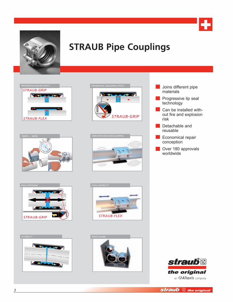
Joins different pipe materials
Progressive lip seal technology
Can be installed with- out fire and explosion risk
Detachable and reusable
Economical repair conception
Over 180 approvals worldwide
STRAUB Pipe Couplings
VIBRATION AND NOISE DAMPING
High-Performance Pipe Couplings • 1-877-5-STRAUB �
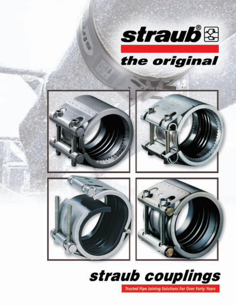
The dependable plain end coupling system that SAVES TIME, SAVES MONEY and SAVES SPACE. The STRAUB coupling is a patented mechanical coupling system for joining plain end pipe in sizes 3⁄4" through 120".
HI-PErfOrMANCE PIPE COuPlINgS
STRAUB-FLEX
STRAUB-METAL-GRIP
Welded Joint
Flanged Joint
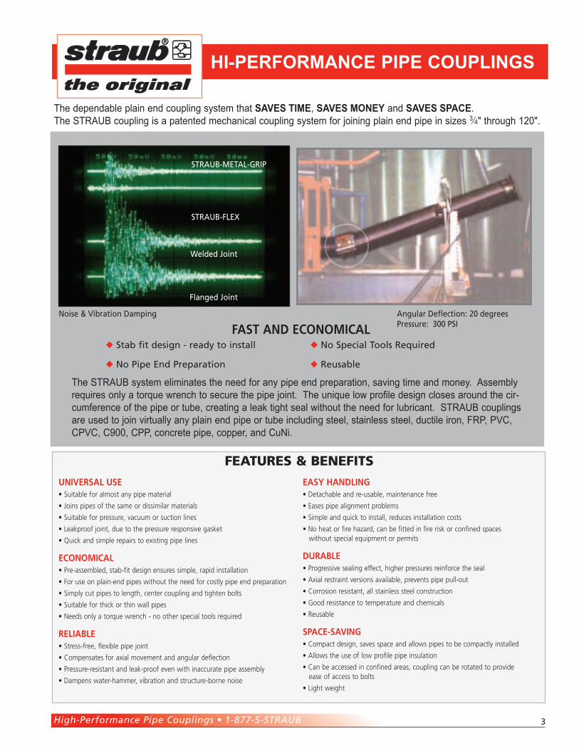
Angular Deflection: �0 degreesPressure: �00 PSIFAST And ECOnOMICAL
Stab fit design - ready to install No Special Tools Required
No Pipe End Preparation Reusable
The STRAUB system eliminates the need for any pipe end preparation, saving time and money. Assembly requires only a torque wrench to secure the pipe joint. The unique low profile design closes around the cir-cumference of the pipe or tube, creating a leak tight seal without the need for lubricant. STRAUB couplings are used to join virtually any plain end pipe or tube including steel, stainless steel, ductile iron, FRP, PVC, CPVC, C900, CPP, concrete pipe, copper, and CuNi.
Noise & Vibration Damping
UnIvERSAL USE• Suitable for almost any pipe material
• Joins pipes of the same or dissimilar materials
• Suitable for pressure, vacuum or suction lines
• Leakproof joint, due to the pressure responsive gasket
• Quick and simple repairs to existing pipe lines
ECOnOMICAL• Pre-assembled, stab-fit design ensures simple, rapid installation
• For use on plain-end pipes without the need for costly pipe end preparation
• Simply cut pipes to length, center coupling and tighten bolts
• Suitable for thick or thin wall pipes
• Needs only a torque wrench - no other special tools required
RELIABLE• Stress-free, flexible pipe joint
• Compensates for axial movement and angular deflection
• Pressure-resistant and leak-proof even with inaccurate pipe assembly
• Dampens water-hammer, vibration and structure-borne noise
EASy hAndLIng• Detachable and re-usable, maintenance free
• Eases pipe alignment problems
• Simple and quick to install, reduces installation costs
• No heat or fire hazard, can be fitted in fire risk or confined spaces without special equipment or permits
dURABLE• Progressive sealing effect, higher pressures reinforce the seal
• Axial restraint versions available, prevents pipe pull-out
• Corrosion resistant, all stainless steel construction
• Good resistance to temperature and chemicals
• Reusable
SPACE-SAvIng• Compact design, saves space and allows pipes to be compactly installed
• Allows the use of low profile pipe insulation
• Can be accessed in confined areas, coupling can be rotated to provide ease of access to bolts
• Light weight
Features & BeneFits
�
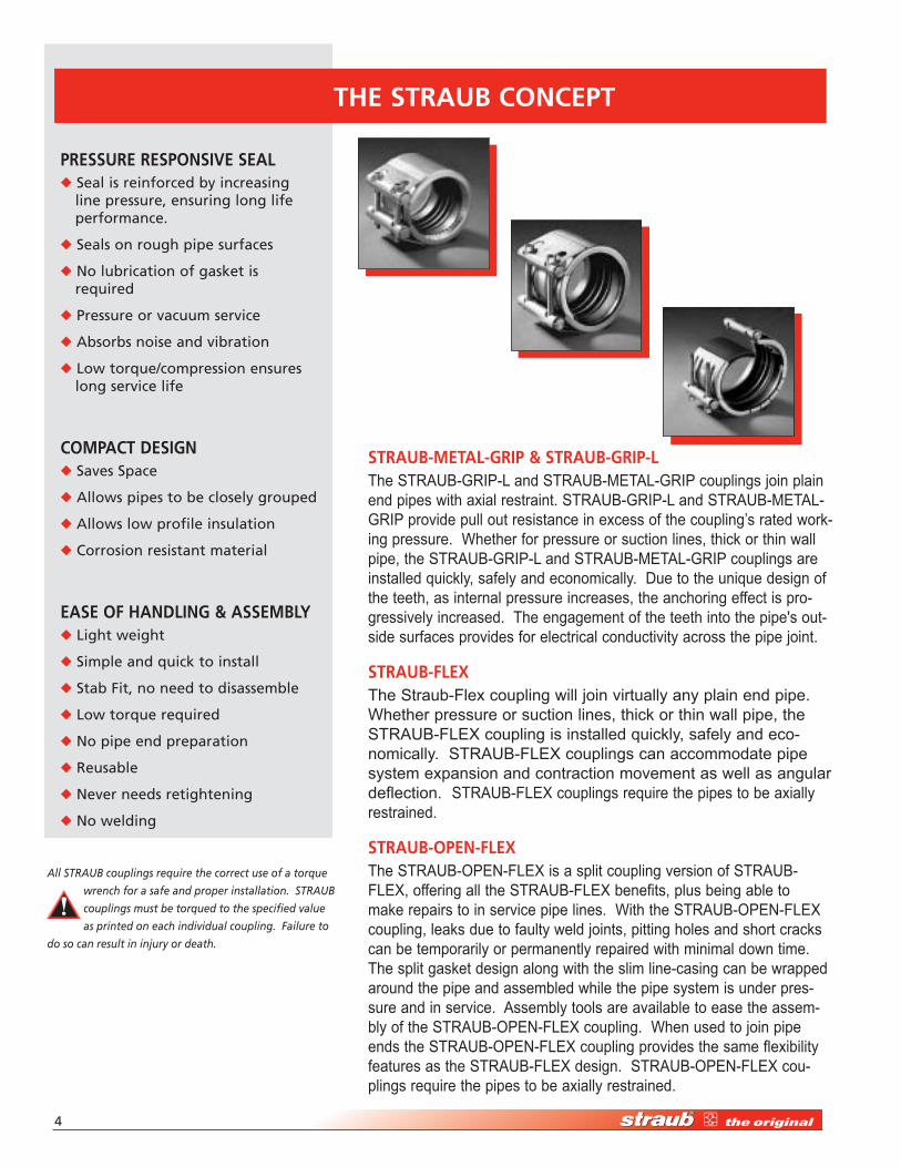
STRAUB-METAL-gRIP & STRAUB-gRIP-LThe STRAUB-GRIP-L and STRAUB-METAL-GRIP couplings join plain end pipes with axial restraint. STRAUB-GRIP-L and STRAUB-METAL-GRIP provide pull out resistance in excess of the coupling’s rated work-ing pressure. Whether for pressure or suction lines, thick or thin wall pipe, the STRAUB-GRIP-L and STRAUB-METAL-GRIP couplings are installed quickly, safely and economically. Due to the unique design of the teeth, as internal pressure increases, the anchoring effect is pro-gressively increased. The engagement of the teeth into the pipe's out-side surfaces provides for electrical conductivity across the pipe joint.
STRAUB-FLExThe Straub-Flex coupling will join virtually any plain end pipe. Whether pressure or suction lines, thick or thin wall pipe, the STRAUB-FLEX coupling is installed quickly, safely and eco-nomically. STRAUB-FLEX couplings can accommodate pipe system expansion and contraction movement as well as angular deflection. STRAUB-FLEX couplings require the pipes to be axially restrained.
STRAUB-OPEn-FLExThe STRAUB-OPEN-FLEX is a split coupling version of STRAUB-FLEX, offering all the STRAUB-FLEX benefits, plus being able to make repairs to in service pipe lines. With the STRAUB-OPEN-FLEX coupling, leaks due to faulty weld joints, pitting holes and short cracks can be temporarily or permanently repaired with minimal down time. The split gasket design along with the slim line-casing can be wrapped around the pipe and assembled while the pipe system is under pres-sure and in service. Assembly tools are available to ease the assem-bly of the STRAUB-OPEN-FLEX coupling. When used to join pipe ends the STRAUB-OPEN-FLEX coupling provides the same flexibility features as the STRAUB-FLEX design. STRAUB-OPEN-FLEX cou-plings require the pipes to be axially restrained.
PRESSURE RESPOnSIvE SEAL Seal is reinforced by increasing
line pressure, ensuring long life performance.
Seals on rough pipe surfaces
No lubrication of gasket is required
Pressure or vacuum service
Absorbs noise and vibration
Low torque/compression ensures long service life
COMPACT dESIgn Saves Space
Allows pipes to be closely grouped
Allows low profile insulation
Corrosion resistant material
EASE OF hAndLIng & ASSEMBLy Light weight
Simple and quick to install
Stab Fit, no need to disassemble
Low torque required
No pipe end preparation
Reusable
Never needs retightening
No welding
ThE STRAUB COnCEPT
All STRAUB couplings require the correct use of a torque
wrench for a safe and proper installation. STRAUB
couplings must be torqued to the specified value
as printed on each individual coupling. Failure to
do so can result in injury or death.
High-Performance Pipe Couplings • 1-877-5-STRAUB �
ThE BASIC COnCEPT
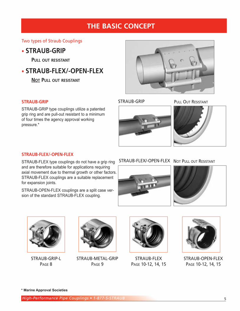
STRAUB-FLEX type couplings do not have a grip ring and are therefore suitable for applications requiring axial movement due to thermal growth or other factors. STRAUB-FLEX couplings are a suitable replacement for expansion joints.
STRAUB-OPEN-FLEX couplings are a split case ver-sion of the standard STRAUB-FLEX coupling.
STRAUB-METAL-GRIP PAGE 9
STRAUB-GRIP-LPAGE 8
STRAUB-FLEXPAGE 10-12, 14, 15
STRAUB-OPEN-FLEX PAGE 10-12, 14, 15
NOT PULL OUT RESISTANT
PULL OUT RESISTANTSTRAUB-GRIP
STRAUB-FLEX/-OPEN-FLEX
STRAUB-GRIP type couplings utilize a patented grip ring and are pull-out resistant to a minimum of four times the agency approval working pressure.*
Two types of Straub Couplings
• STRAUB-GRIP
PUll oUT ReSISTAnT
• STRAUB-FleX/-oPen-FleX noT PUll oUT ReSISTAnT
STRAUB-gRIP
STRAUB-FLEx/-OPEn-FLEx
* Marine Approval Societies
�
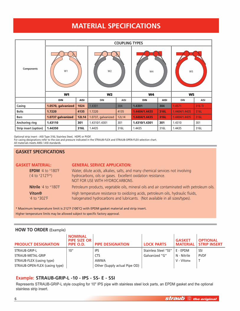
Components
COUPLIng TyPES
W1 W2 W4 W5
W1 W2 W4 W5Din aisi dIn AISI Din aisi dIn AISI
Casing 1.0570, galvanized 1024 1.��01 �0� 1.4301 304 1.��71 �1� TI
Bolts 1.7220 4135 1.7��0 �1�� 1.4404/1.4435 316L 1.��0�/1.���� �1�L
Bars 1.0737 galvanized 12L14 1.07�7, galvanized 1�L1� 1.4404/1.4435 316L 1.��0�/1.���� �1�L
Anchoring ring 1.43110 301 1.��10/1.��01 �01 1.4310/1.4301 301 1.��10 �01
Strip insert (option) 1.44350 316L 1.���� �1�L 1.���� �1�L 1.���� �1�L
gASkET SPECIFICATIOnS
gASkET MATERIAL: gEnERAL SERvICE APPLICATIOn: EPdM -4 to +180˚F Water, dilute acids, alkalies, salts, and many chemical services not involving (-4 to +212˚F*) hydrocarbons, oils or gases. Excellent oxidation resistance. NOT FOR USE WITH HYDROCARBONS.
nitrile -4 to +180˚F Petroleum products, vegetable oils, mineral oils and air contaminated with petroleum oils.
viton® High temperature resistance to oxidizing acids, petroleum oils, hydraulic fluids, -4 to +302˚F halogenated hydrocarbons and lubricants. (Not available in all sizes/types). * Maximum temperature limit is �1�˚F (100˚C) with EPDM gasket material and strip insert.
Higher temperature limits may be allowed subject to specific factory approval.
hOw TO ORdER (Example)
Example: STRAUB-gRIP-L -10 - IPS - SS- E - SSIRepresents STRAUB-GRIP-L style coupling for 10" IPS pipe with stainless steel lock parts, an EPDM gasket and the optional stainless strip insert.
PROdUCT dESIgnATIOn
nOMInAL PIPE SIzE OR PIPE O.d. PIPE dESIgnATIOn LOCk PARTS
gASkET MATERIAL
OPTIOnAL STRIP InSERT
STRAUB-GRIP-L 10" IPS Stainless Steel “SS” E - EPDM SSISTRAUB-METAL-GRIP CTS Galvanized “G” N - Nitrile PVDFSTRAUB-FLEX (casing type) AWWA V - Viton® TSTRAUB-OPEN-FLEX (casing type) Other (Supply actual Pipe OD)
Optional strip insert - AISI Type �1�L Stainless Steel, HDPE or PVDF.For casing designations refer to the size and pressure indicated in the STRAUB-FLEX and STRAUB-OPEN-FLEX selection chart.All materials meets ANSI / AISI standards.
MATERIAL SPECIFICATIOnS
High-Performance Pipe Couplings • 1-877-5-STRAUB �
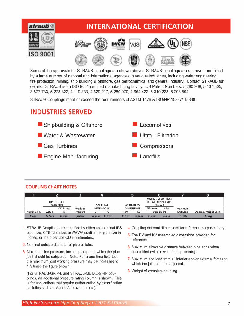
Some of the approvals for Straub couplings are shown above. Straub couplings are approved and listed by a large number of national and international agencies in various industries, including water engineering, fire protection, mining, ship building & offshore, gas petrochemical and general industry. Contact Straub for details. Straub is an ISO 9001 certified manufacturing facility. uS Patent Numbers: 5 280 969, 5 137 305, 3 877 733, 5 273 322, 4 119 333, 4 629 217, 5 280 970, 4 664 422, 5 310 223, 5 203 594.
Straub Couplings meet or exceed the requirements of aStM 1476 & ISO/NP-15837/ 15838.
1. Straub Couplings are identified by either the nominal IPS pipe size, CtS tube size, or aWWa ductile iron pipe size in inches, or the pipe/tube OD in millimeters.
2. Nominal outside diameter of pipe or tube.
3. Maximum line pressure, including surge, to which the pipe joint should be subjected. Note: For a one-time field test the maximum joint working pressure may be increased to 11/2 times the figure shown.
(For Straub-GrIP-L and Straub-MEtaL-GrIP cou-plings, an additional pressure rating column is shown. this is for applications that require authorization by classification societies such as Marine approval bodies.)
4. Coupling external dimensions for reference purposes only.
5. the DV and KV assembled dimensions provided for reference.
6. Maximum allowable distance between pipe ends when assembled (with or without strip inserts).
7. Maximum end load from all interior and/or external forces to which the joint can be subjected.
8. Weight of complete coupling.
1 2 3 4 5 6 7 8
Nominal IPS
PIPe OutSIde dIameter
Working Pressure
COuPlINg dImeNSIONS
aSSembled dImeNSIONS
maxImum dIStaNCe betWeeN PIPe eNdS
(rmax.)maximum end load approx. Weight eachactual
Od range Without With+/- b C dV KV Strip insert
Inches In./mm In./mm psi/bar In./mm In./mm In./mm In./mm In./mm In./mm Lbs./kN Lbs./kg
INterNatIONal CertIfICatION
INduStrIeS SerVed
COuPlINg Chart NOteS
Shipbuilding & Offshore
Water & Wastewater
Gas turbines
Engine Manufacturing
Locomotives
ultra - Filtration
Compressors
Landfills
�
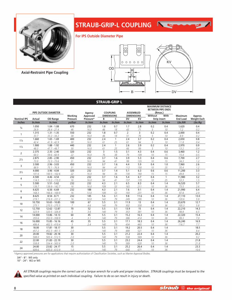
STRAUB-gRIP-L COUPLIng
RC
B DV
KV
OD
strauB-GriP L
nominal IPS
PIPE OUTSIdE dIAMETERworking Pressure
Agency Approved Pressure*
COUPLIng dIMEnSIOnS
ASSEMBLEd dIMEnSIOnS
MAxIMUM dISTAnCE BETwEEn PIPE EndS
(Rmax.)Maximum End Load
Approx. weight EachActual
without withOd Range B C dv kv Strip insert
Inches In./mm In./mm psi/bar In./mm In./mm In./mm In./mm In./mm In./mm In./mm Lbs./kN Lbs./kg
�⁄�1.0�0 1.0� - 1.0� �70 ��� 1.� 0.7 1.7 �.� 0.� 0.� 1,��0 0.�26.9 26.4 - 27.4 46 16.0 46 18 43 71 5 10 7.2 0.2
11.�1� 1.�1 - 1.�� ��0 ��� 1.� 0.7 � � 0.� 0.� �,000 0.�33.7 33.2 - 34.2 38 16.0 46 18 51 76 5 10 8.9 0.2
11⁄�1.��0 1.�� - 1.�9 �00 ��� �.� 1 �.� �.7 0.� 0.� �,��0 0.�42.4 41.9 - 42.9 30 16.0 61 25 61 94 5 10 11.8 0.4
11⁄�1.900 1.�� - 1.9� ��0 ��� �.� 1 �.� �.9 0.� 0.� �,970 0.948.3 47.7 - 48.7 30 16.0 61 25 66 99 5 10 13.2 0.4
��.�7� �.�� - �.�0 ��0 ��� � 1.� �.1 �.� 0.� 0.� �,��0 1.�60.3 59.6 - 60.9 22 16.0 76 38 79 109 10 15 15.4 0.5
�1⁄��.�7� �.�� - �.90 ��0 ��� �.7 1.� �.9 �.� 0.� 0.� 7,700 �.773.0 72.3 - 73.6 31 16.0 94 41 99 135 10 15 34.3 1.2
� �.�00 �.9� - �.0� ��0 ��� �.7 1.� �.� �.9 0.� 1.0 7,9�0 �.�88.9 75.1 - 76.9 31 16.0 94 41 112 150 10 25 35.4 1.2
�1⁄��.000 �.9� - �.0� ��0 ��� �.7 1.� �.1 �.� 0.� 0.� 11,�00 �.�101.6 100.5 - 102.6 22 16.0 94 36 130 160 15 15 49.8 1.5
��.�00 �.�� - �.�� ��� ��� �.7 1.� �.� �.7 0.� 1 11,9�0 �.�114.3 113.2 - 115.3 16 16.0 94 41 137 170 10 25 53.3 1.5
��.�00 �.�1 - �.�� ��� ��� �.� �.1 �.� �.� 0.� 1.� 1�,��0 �.7139.7 139.9 - 142.7 16 16.0 109 53 165 211 10 36 73.5 2.6
��.��� �.�� - �.�9 ��� 1�� �.� �.1 7.� 9.1 0.� 1.� �1,990 �.�168.3 166.6 - 169.9 16 13.0 109 53 193 231 10 36 97.8 2.9
��.��� �.�� - �.71 ��� 1�� �.� �.1 9.� 11.� 0.� 1.� �7,110 1�.0219.1 216.9 - 221.2 16 10.0 142 79 249 295 10 36 120.6 5.9
1010.7�0 10.�� - 10.�� 100 �7 �.� �.1 11.9 1� 0.� 1.� ��,�70 1�.7273.1 270.5 - 275.5 7 4.6 140 79 302 330 10 36 105.3 5.8
1�1�.7�0 1�.�� - 1�.�7 70 �� �.� �.1 1�.9 1� 0.� 1.� ��,�10 1�.�323.9 320.5 - 326.8 5 3.6 140 79 353 381 10 36 98.8 6.5
1�1�.000 1�.�� - 1�.1� �0 �� �.� �.1 1�.� 1�.� 0.� 1.� ��,��0 1�.�355.6 352.0 - 358.9 4 3.1 140 79 386 414 10 36 99.3 7.0
1�1�.000 1�.�� - 1�.1� �� �� �.� �.1 17.1 1�.� 0.� 1.� ��,��0 1�.9406.4 402.5 - 410.4 3 2.4 140 79 434 465 10 36 116.7 7.7
1�1�.00 17.�1 - 1�.17 �0 �.� �.1 19.� �0.� 0.� 1.� 1�.�457.2 452.3 - 461.5 2.0 140 79 488 521 10 36 8.4
�0�0.00 19.�� - �0.1� �0 �.� �.1 �1.� ��.� 0.� 1.� �0.�508.0 503.4 - 512.5 2.0 140 79 538 569 10 36 9.2
����.00 �1.�� - ��.19 �0 �.� �.1 ��.� ��.� 0.� 1.� �1.�558.8 554.4 - 563.6 2.0 140 79 589 620 10 36 21.8
����.00 ��.�� - ��.17 1� �.� �.1 ��.� ��.� 0.� 1.� ��.�609.6 605.0 - 613.9 1.0 140 79 640 671 10 36 10.6
*Agency approved pressures are for applications that require authorization of Classification Societies, such as Marine Approval Bodies.
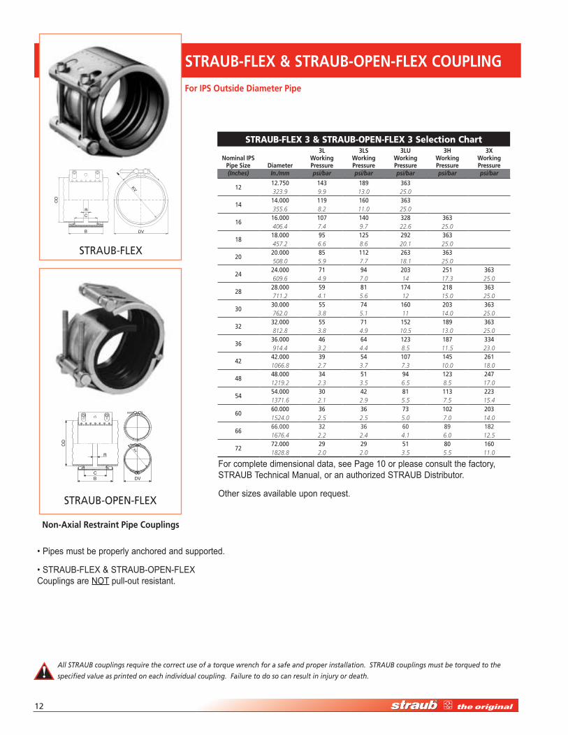
For IPS Outside diameter Pipe
Axial-Restraint Pipe Coupling
All STRAUB couplings require the correct use of a torque wrench for a safe and proper installation. STRAUB couplings must be torqued to the
specified value as printed on each individual coupling. Failure to do so can result in injury or death.
�/�" - �": W� only 10" - ��": W� or W�
High-Performance Pipe Couplings • 1-877-5-STRAUB 9
B
R
C
ODKV
DV
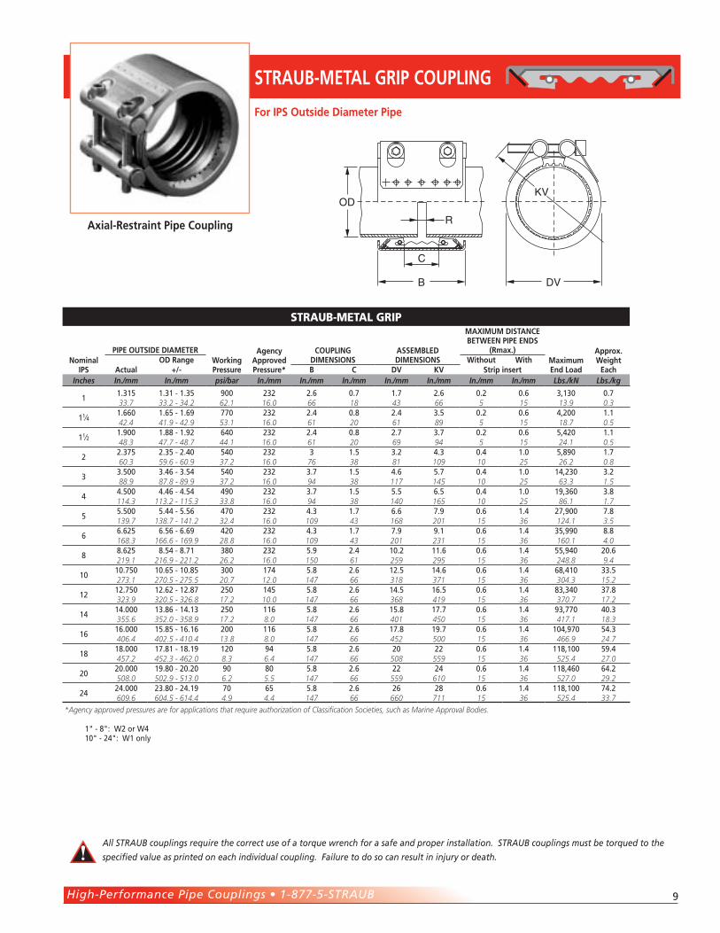
strauB-MetaL GriP
nominal IPS
PIPE OUTSIdE dIAMETERworking Pressure
Agency Approved Pressure*
COUPLIng dIMEnSIOnS
ASSEMBLEd dIMEnSIOnS
MAxIMUM dISTAnCE BETwEEn PIPE EndS
(Rmax.)Maximum End Load
Approx. weight
EachActualOd Range without with
+/- B C dv kv Strip insertInches In./mm In./mm psi/bar In./mm In./mm In./mm In./mm In./mm In./mm In./mm Lbs./kN Lbs./kg
11.�1� 1.�1 - 1.�� 900 ��� �.� 0.7 1.7 �.� 0.� 0.� �,1�0 0.733.7 33.2 - 34.2 62.1 16.0 66 18 43 66 5 15 13.9 0.3
11⁄�1.��0 1.�� - 1.�9 770 ��� �.� 0.� �.� �.� 0.� 0.� �,�00 1.142.4 41.9 - 42.9 53.1 16.0 61 20 61 89 5 15 18.7 0.5
11⁄�1.900 1.�� - 1.9� ��0 ��� �.� 0.� �.7 �.7 0.� 0.� �,��0 1.148.3 47.7 - 48.7 44.1 16.0 61 20 69 94 5 15 24.1 0.5
��.�7� �.�� - �.�0 ��0 ��� � 1.� �.� �.� 0.� 1.0 �,�90 1.760.3 59.6 - 60.9 37.2 16.0 76 38 81 109 10 25 26.2 0.8
��.�00 �.�� - �.�� ��0 ��� �.7 1.� �.� �.7 0.� 1.0 1�,��0 �.�88.9 87.8 - 89.9 37.2 16.0 94 38 117 145 10 25 63.3 1.5
��.�00 �.�� - �.�� �90 ��� �.7 1.� �.� �.� 0.� 1.0 19,��0 �.�114.3 113.2 - 115.3 33.8 16.0 94 38 140 165 10 25 86.1 1.7
��.�00 �.�� - �.�� �70 ��� �.� 1.7 �.� 7.9 0.� 1.� �7,900 7.�139.7 138.7 - 141.2 32.4 16.0 109 43 168 201 15 36 124.1 3.5
��.��� �.�� - �.�9 ��0 ��� �.� 1.7 7.9 9.1 0.� 1.� ��,990 �.�168.3 166.6 - 169.9 28.8 16.0 109 43 201 231 15 36 160.1 4.0
��.��� �.�� - �.71 ��0 ��� �.9 �.� 10.� 11.� 0.� 1.� ��,9�0 �0.�219.1 216.9 - 221.2 26.2 16.0 150 61 259 295 15 36 248.8 9.4
1010.7�0 10.�� - 10.�� �00 17� �.� �.� 1�.� 1�.� 0.� 1.� ��,�10 ��.�273.1 270.5 - 275.5 20.7 12.0 147 66 318 371 15 36 304.3 15.2
1�1�.7�0 1�.�� - 1�.�7 ��0 1�� �.� �.� 1�.� 1�.� 0.� 1.� ��,��0 �7.�323.9 320.5 - 326.8 17.2 10.0 147 66 368 419 15 36 370.7 17.2
1�1�.000 1�.�� - 1�.1� ��0 11� �.� �.� 1�.� 17.7 0.� 1.� 9�,770 �0.�355.6 352.0 - 358.9 17.2 8.0 147 66 401 450 15 36 417.1 18.3
1�1�.000 1�.�� - 1�.1� �00 11� �.� �.� 17.� 19.7 0.� 1.� 10�,970 ��.�406.4 402.5 - 410.4 13.8 8.0 147 66 452 500 15 36 466.9 24.7
1�1�.000 17.�1 - 1�.19 1�0 9� �.� �.� �0 �� 0.� 1.� 11�,100 �9.�457.2 452.3 - 462.0 8.3 6.4 147 66 508 559 15 36 525.4 27.0
�0�0.000 19.�0 - �0.�0 90 �0 �.� �.� �� �� 0.� 1.� 11�,��0 ��.�508.0 502.9 - 513.0 6.2 5.5 147 66 559 610 15 36 527.0 29.2
����.000 ��.�0 - ��.19 70 �� �.� �.� �� �� 0.� 1.� 11�,100 7�.�609.6 604.5 - 614.4 4.9 4.4 147 66 660 711 15 36 525.4 33.7
*Agency approved pressures are for applications that require authorization of Classification Societies, such as Marine Approval Bodies.
For IPS Outside diameter Pipe
STRAUB-METAL gRIP COUPLIng
Axial-Restraint Pipe Coupling
All STRAUB couplings require the correct use of a torque wrench for a safe and proper installation. STRAUB couplings must be torqued to the
specified value as printed on each individual coupling. Failure to do so can result in injury or death.
1" - �": W� or W� 10" - ��": W1 only
10
B
CR
OD
D
KV
V
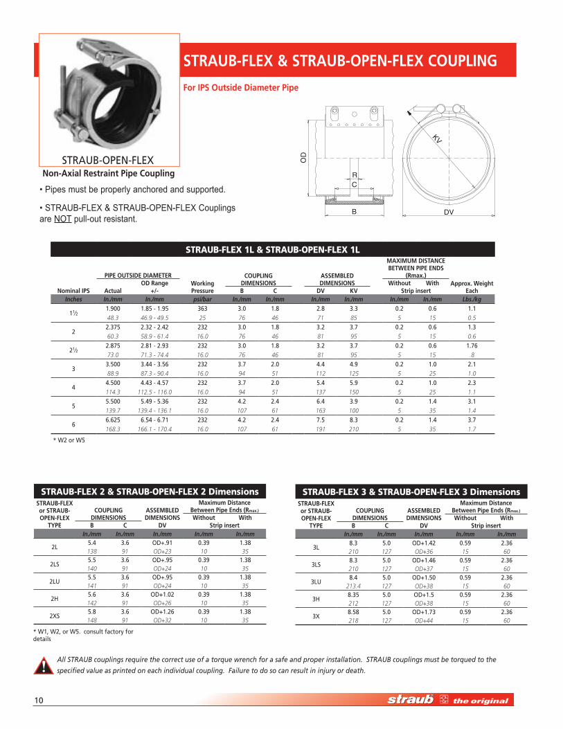
FLEx COUPLIngstrauB-FLeX 1L & strauB-OPen-FLeX 1L
nominal IPS
PIPE OUTSIdE dIAMETERworking Pressure
COUPLIng dIMEnSIOnS
ASSEMBLEd dIMEnSIOnS
MAxIMUM dISTAnCE BETwEEn PIPE EndS
(Rmax.)Approx. weight
EachActualOd Range without with
+/- B C dv kv Strip insertInches In./mm In./mm psi/bar In./mm In./mm In./mm In./mm In./mm In./mm Lbs./kg
11⁄�1.900 1.�� - 1.9� ��� �.0 1.� �.� �.� 0.� 0.� 1.148.3 46.9 - 49.5 25 76 46 71 85 5 15 0.5
��.�7� �.�� - �.�� ��� �.0 1.� �.� �.7 0.� 0.� 1.�60.3 58.9 - 61.4 16.0 76 46 81 95 5 15 0.6
�1⁄��.�7� �.�1 - �.9� ��� �.0 1.� �.� �.7 0.� 0.� 1.7�73.0 71.3 - 74.4 16.0 76 46 81 95 5 15 .8
��.�00 �.�� - �.�� ��� �.7 �.0 �.� �.9 0.� 1.0 �.188.9 87.3 - 90.4 16.0 94 51 112 125 5 25 1.0
��.�00 �.�� - �.�7 ��� �.7 �.0 �.� �.9 0.� 1.0 �.�114.3 112.5 - 116.0 16.0 94 51 137 150 5 25 1.1
��.�00 �.�9 - �.�� ��� �.� �.� �.� �.9 0.� 1.� �.1139.7 139.4 - 136.1 16.0 107 61 163 100 5 35 1.4
��.��� �.�� - �.71 ��� �.� �.� 7.� �.� 0.� 1.� �.7168.3 166.1 - 170.4 16.0 107 61 191 210 5 35 1.7
strauB-FLeX 2 & strauB-OPen-FLeX 2 DimensionsSTRAUB-FLEx or STRAUB-OPEn-FLEx
TyPE
COUPLIng dIMEnSIOnS
ASSEMBLEd dIMEnSIOnS
Maximum distance Between Pipe Ends (Rmax.)
without withB C dv Strip insert
In./mm In./mm In./mm In./mm In./mm
�L�.� �.� OD+.91 0.�9 1.��138 91 OD+23 10 35
�LS�.� �.� OD+.9� 0.�9 1.��140 91 OD+24 10 35
�LU�.� �.� OD+.9� 0.�9 1.��141 91 OD+24 10 35
�H�.� �.� OD+1.0� 0.�9 1.��142 91 OD+26 10 35
�XS�.� �.� OD+1.�� 0.�9 1.��148 91 OD+32 10 35
strauB-FLeX 3 & strauB-OPen-FLeX 3 DimensionsSTRAUB-FLEx or STRAUB-OPEn-FLEx
TyPE
COUPLIng dIMEnSIOnS
ASSEMBLEd dIMEnSIOnS
Maximum distance Between Pipe Ends (Rmax.)
without withB C dv Strip insert
In./mm In./mm In./mm In./mm In./mm
�L�.� �.0 OD+1.�� 0.�9 �.��210 127 OD+36 15 60
�LS�.� �.0 OD+1.�� 0.�9 �.��210 127 OD+37 15 60
�LU�.� �.0 OD+1.�0 0.�9 �.��
213.4 127 OD+38 15 60
�H�.�� �.0 OD+1.� 0.�9 �.��212 127 OD+38 15 60
�X�.�� �.0 OD+1.7� 0.�9 �.��218 127 OD+44 15 60
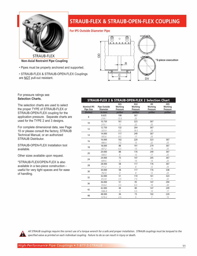
STRAUB-FLEx & STRAUB-OPEn-FLEx COUPLIng
For IPS Outside diameter Pipe
non-Axial Restraint Pipe Coupling
• Pipes must be properly anchored and supported.
• STRAUB-FLEX & STRAUB-OPEN-FLEX Couplings are NOT pull-out resistant.
All STRAUB couplings require the correct use of a torque wrench for a safe and proper installation. STRAUB couplings must be torqued to the
specified value as printed on each individual coupling. Failure to do so can result in injury or death.
STRAUB-OPEN-FLEX
* W� or W�
* W1, W�, or W�. consult factory for details
High-Performance Pipe Couplings • 1-877-5-STRAUB 11
strauB-FLeX 3 & strauB-OPen-FLeX 3 DimensionsSTRAUB-FLEx or STRAUB-OPEn-FLEx
TyPE
COUPLIng dIMEnSIOnS
ASSEMBLEd dIMEnSIOnS
Maximum distance Between Pipe Ends (Rmax.)
without withB C dv Strip insert
In./mm In./mm In./mm In./mm In./mm
�L�.� �.0 OD+1.�� 0.�9 �.��210 127 OD+36 15 60
�LS�.� �.0 OD+1.�� 0.�9 �.��210 127 OD+37 15 60
�LU�.� �.0 OD+1.�0 0.�9 �.��
213.4 127 OD+38 15 60
�H�.�� �.0 OD+1.� 0.�9 �.��212 127 OD+38 15 60
�X�.�� �.0 OD+1.7� 0.�9 �.��218 127 OD+44 15 60
For pressure ratings see Selection Charts.
The selection charts are used to select the proper TYPE of STRAUB-FLEX or STRAUB-OPEN-FLEX coupling for the application pressure. Separate charts are used for the TYPE 2 and 3 designs.
For complete dimensional data, see Page 10 or please consult the factory, STRAUB Technical Manual, or an authorized STRAUB Distributor.
STRAUB-OPEN-FLEX Installation tool available.
Other sizes available upon request.
*STRAUB-FLEX/OPEN-FLEX is also available in a two-piece construction - useful for very tight spaces and for ease of handling.
CB D
R
V
OD
strauB-FLeX 2 & strauB-OPen-FLeX 2 selection Chart
nominal IPS Pipe Size
Pipe Outside diameter
2LSworking Pressure
2LUworking Pressure
2hworking Pressure
2xSworking Pressure
(Inches) In./mm psi/bar psi/bar psi/bar psi/bar
��.��� 19� ��7219.1 13.5 25
1010.7�0 1�1 ��� ��7273.1 11 22 25
1�1�.7�0 1�� ��� ��7323.9 9.5 18.5 25
1�1�.000 117 ��9 ��7355.6 8.5 17 25
1�1�.000 10� ��0 ��� ��7406.4 7.5 15 22 25
1�1�.000 �� 191 �79 ��7457.2 6.5 13 19 25
�0�0.000 �� 17� ��9 ��7508.0 6 12 17 25
����.000 7� 1�7 �0� ��7609.6 5 10 14 25
����.000 �� 117 17� ��7711.2 4 8 12 25
�0�0.000 �� 117 17� ���762.0 4 8 12 23
����.000 �1 110 1�1 ���812.8 3.5 7.5 11 22
����.000 �1 9� 1�7 �9�914.4 3.5 6.5 10 20
����.000 �� �0 1�7 ��91066.8 3 5.5 10 17
����.000 �� 7� 10� ��01219.2 2.5 5 7 15
For IPS Outside diameter Pipe
STRAUB-FLEx & STRAUB-OPEn-FLEx COUPLIng
non-Axial Restraint Pipe Coupling
All STRAUB couplings require the correct use of a torque wrench for a safe and proper installation. STRAUB couplings must be torqued to the
specified value as printed on each individual coupling. Failure to do so can result in injury or death.
• Pipes must be properly anchored and supported.
• STRAUB-FLEX & STRAUB-OPEN-FLEX Couplings are NOT pull-out resistant.
*2-piece executionSTRAUB-FLEX
1�
CB D
R
V
OD
strauB-FLeX 3 & strauB-OPen-FLeX 3 selection Chart
nominal IPS Pipe Size diameter
3Lworking Pressure
3LSworking Pressure
3LUworking Pressure
3hworking Pressure
3xworking Pressure
(Inches) In./mm psi/bar psi/bar psi/bar psi/bar psi/bar
1�1�.7�0 1�� 1�9 ���323.9 9.9 13.0 25.0
1�1�.000 119 1�0 ���355.6 8.2 11.0 25.0
1�1�.000 107 1�0 ��� ���406.4 7.4 9.7 22.6 25.0
1�1�.000 9� 1�� �9� ���457.2 6.6 8.6 20.1 25.0
�0�0.000 �� 11� ��� ���508.0 5.9 7.7 18.1 25.0
����.000 71 9� �0� ��1 ���609.6 4.9 7.0 14 17.3 25.0
����.000 �9 �1 17� �1� ���711.2 4.1 5.6 12 15.0 25.0
�0�0.000 �� 7� 1�0 �0� ���762.0 3.8 5.1 11 14.0 25.0
����.000 �� 71 1�� 1�9 ���812.8 3.8 4.9 10.5 13.0 25.0
����.000 �� �� 1�� 1�7 ���914.4 3.2 4.4 8.5 11.5 23.0
����.000 �9 �� 107 1�� ��11066.8 2.7 3.7 7.3 10.0 18.0
����.000 �� �1 9� 1�� ��71219.2 2.3 3.5 6.5 8.5 17.0
����.000 �0 �� �1 11� ���1371.6 2.1 2.9 5.5 7.5 15.4
�0�0.000 �� �� 7� 10� �0�1524.0 2.5 2.5 5.0 7.0 14.0
����.000 �� �� �0 �9 1��1676.4 2.2 2.4 4.1 6.0 12.5
7�7�.000 �9 �9 �1 �0 1�01828.8 2.0 2.0 3.5 5.5 11.0
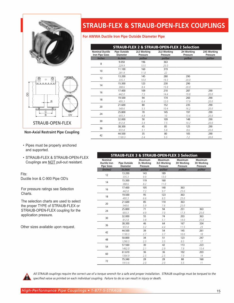
STRAUB-FLEx & STRAUB-OPEn-FLEx COUPLIng
For IPS Outside diameter Pipe
B
CR
OD
D
KV
V
STRAUB-FLEX
STRAUB-OPEN-FLEX
For complete dimensional data, see Page 10 or please consult the factory, STRAUB Technical Manual, or an authorized STRAUB Distributor.
Other sizes available upon request.
non-Axial Restraint Pipe Couplings
• Pipes must be properly anchored and supported.
• STRAUB-FLEX & STRAUB-OPEN-FLEX Couplings are NOT pull-out resistant.
All STRAUB couplings require the correct use of a torque wrench for a safe and proper installation. STRAUB couplings must be torqued to the
specified value as printed on each individual coupling. Failure to do so can result in injury or death.
High-Performance Pipe Couplings • 1-877-5-STRAUB 1�
C
B
R
DV
KV
OD
High-Pressure Type
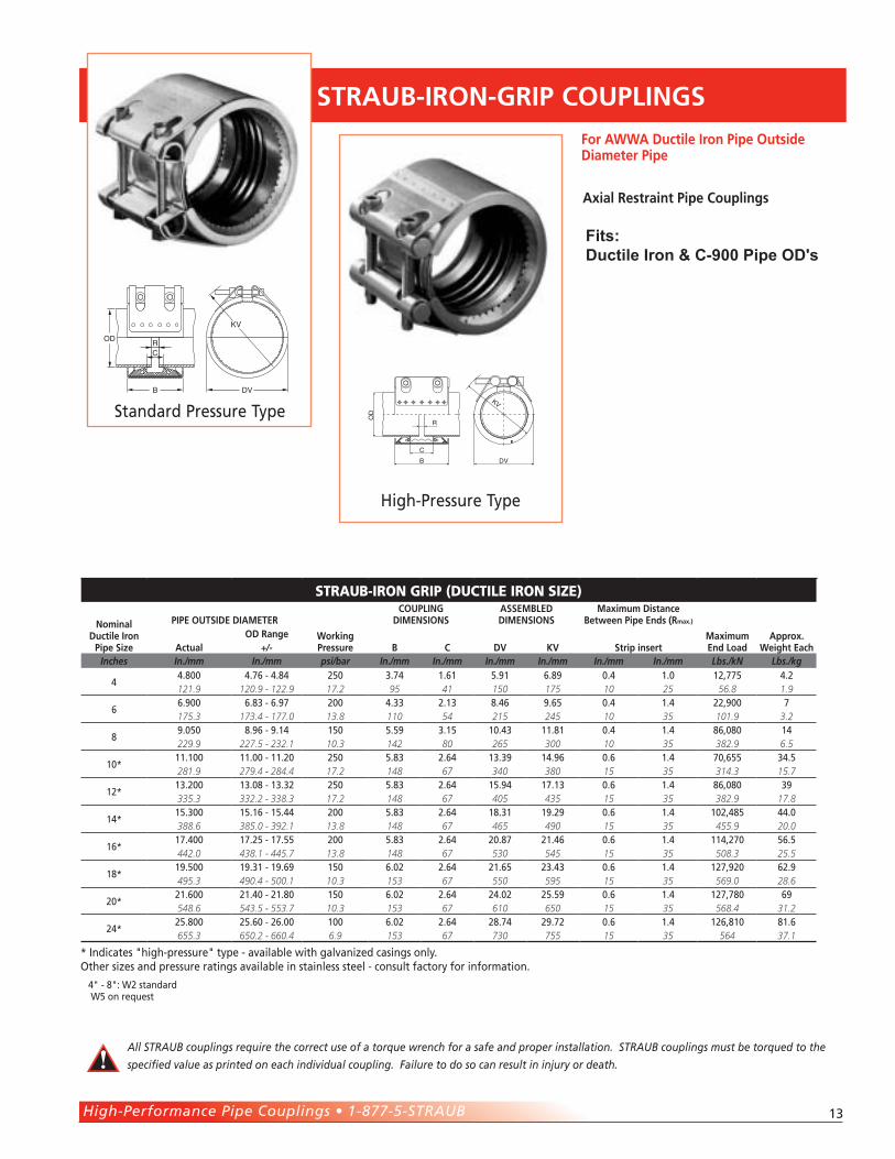
STRAUB-IROn-gRIP COUPLIngS
strauB-irOn GriP (DuCtiLe irOn size)
nominal ductile Iron
Pipe Size
PIPE OUTSIdE dIAMETER
working Pressure
COUPLIng dIMEnSIOnS
ASSEMBLEd dIMEnSIOnS
Maximum distance Between Pipe Ends (Rmax.)
Maximum End Load
Approx. weight Each
Od RangeActual +/- B C dv kv Strip insert
Inches In./mm In./mm psi/bar In./mm In./mm In./mm In./mm In./mm In./mm Lbs./kN Lbs./kg
��.�00 �.7� - �.�� ��0 �.7� 1.�1 �.91 �.�9 0.� 1.0 1�,77� �.�121.9 120.9 - 122.9 17.2 95 41 150 175 10 25 56.8 1.9
��.900 �.�� - �.97 �00 �.�� �.1� �.�� 9.�� 0.� 1.� ��,900 7175.3 173.4 - 177.0 13.8 110 54 215 245 10 35 101.9 3.2
�9.0�0 �.9� - 9.1� 1�0 �.�9 �.1� 10.�� 11.�1 0.� 1.� ��,0�0 1�229.9 227.5 - 232.1 10.3 142 80 265 300 10 35 382.9 6.5
10*11.100 11.00 - 11.�0 ��0 �.�� �.�� 1�.�9 1�.9� 0.� 1.� 70,��� ��.�281.9 279.4 - 284.4 17.2 148 67 340 380 15 35 314.3 15.7
1�*1�.�00 1�.0� - 1�.�� ��0 �.�� �.�� 1�.9� 17.1� 0.� 1.� ��,0�0 �9335.3 332.2 - 338.3 17.2 148 67 405 435 15 35 382.9 17.8
1�*1�.�00 1�.1� - 1�.�� �00 �.�� �.�� 1�.�1 19.�9 0.� 1.� 10�,��� ��.0388.6 385.0 - 392.1 13.8 148 67 465 490 15 35 455.9 20.0
1�*17.�00 17.�� - 17.�� �00 �.�� �.�� �0.�7 �1.�� 0.� 1.� 11�,�70 ��.�442.0 438.1 - 445.7 13.8 148 67 530 545 15 35 508.3 25.5
1�*19.�00 19.�1 - 19.�9 1�0 �.0� �.�� �1.�� ��.�� 0.� 1.� 1�7,9�0 ��.9495.3 490.4 - 500.1 10.3 153 67 550 595 15 35 569.0 28.6
�0*�1.�00 �1.�0 - �1.�0 1�0 �.0� �.�� ��.0� ��.�9 0.� 1.� 1�7,7�0 �9548.6 543.5 - 553.7 10.3 153 67 610 650 15 35 568.4 31.2
��*��.�00 ��.�0 - ��.00 100 �.0� �.�� ��.7� �9.7� 0.� 1.� 1��,�10 �1.�655.3 650.2 - 660.4 6.9 153 67 730 755 15 35 564 37.1
For AwwA ductile Iron Pipe Outside diameter Pipe
Standard Pressure Type
RC
B DV
KV
OD
Axial Restraint Pipe Couplings
All STRAUB couplings require the correct use of a torque wrench for a safe and proper installation. STRAUB couplings must be torqued to the
specified value as printed on each individual coupling. Failure to do so can result in injury or death.
* Indicates "high-pressure" type - available with galvanized casings only.Other sizes and pressure ratings available in stainless steel - consult factory for information.
fits:Ductile Iron & C-900 Pipe OD's
�" - �": W� standard W� on request
1�
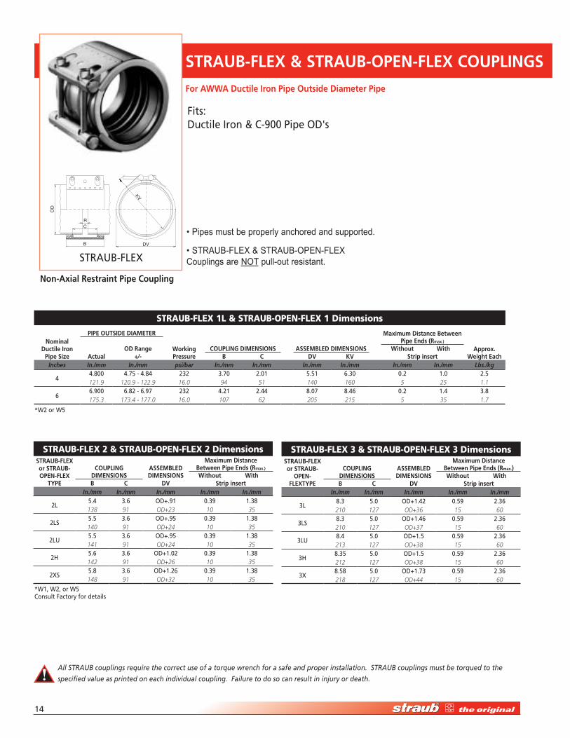
strauB-FLeX 1L & strauB-OPen-FLeX 1 Dimensions
nominal ductile Iron
Pipe Size
PIPE OUTSIdE dIAMETER
working Pressure
COUPLIng dIMEnSIOnS ASSEMBLEd dIMEnSIOnS
Maximum distance Between Pipe Ends (Rmax.)
Approx. weight Each
Od Range without withActual +/- B C dv kv Strip insert
Inches In./mm In./mm psi/bar In./mm In./mm In./mm In./mm In./mm In./mm Lbs./kg
��.�00 �.7� - �.�� ��� �.70 �.01 �.�1 �.�0 0.� 1.0 �.�121.9 120.9 - 122.9 16.0 94 51 140 160 5 25 1.1
��.900 �.�� - �.97 ��� �.�1 �.�� �.07 �.�� 0.� 1.� �.�175.3 173.4 - 177.0 16.0 107 62 205 215 5 35 1.7
strauB-FLeX 2 & strauB-OPen-FLeX 2 DimensionsSTRAUB-FLEx or STRAUB-OPEn-FLEx
TyPE
COUPLIng dIMEnSIOnS
ASSEMBLEd dIMEnSIOnS
Maximum distance Between Pipe Ends (Rmax.)
without withB C dv Strip insert
In./mm In./mm In./mm In./mm In./mm
�L�.� �.� OD+.91 0.�9 1.��138 91 OD+23 10 35
�LS�.� �.� OD+.9� 0.�9 1.��140 91 OD+24 10 35
�LU�.� �.� OD+.9� 0.�9 1.��141 91 OD+24 10 35
�H�.� �.� OD+1.0� 0.�9 1.��142 91 OD+26 10 35
�XS�.� �.� OD+1.�� 0.�9 1.��148 91 OD+32 10 35
strauB-FLeX 3 & strauB-OPen-FLeX 3 DimensionsSTRAUB-FLEx or STRAUB-
OPEn-FLExTyPE
COUPLIng dIMEnSIOnS
ASSEMBLEd dIMEnSIOnS
Maximum distance Between Pipe Ends (Rmax.)without with
B C dv Strip insertIn./mm In./mm In./mm In./mm In./mm
�L�.� �.0 OD+1.�� 0.�9 �.��210 127 OD+36 15 60
�LS�.� �.0 OD+1.�� 0.�9 �.��210 127 OD+37 15 60
�LU�.� �.0 OD+1.� 0.�9 �.��213 127 OD+38 15 60
�H�.�� �.0 OD+1.� 0.�9 �.��212 127 OD+38 15 60
�X�.�� �.0 OD+1.7� 0.�9 �.��218 127 OD+44 15 60
STRAUB-FLEx & STRAUB-OPEn-FLEx COUPLIngS
For AwwA ductile Iron Pipe Outside diameter Pipe
B
CR
OD
D
KV
V
STRAUB-FLEX
non-Axial Restraint Pipe Coupling
• Pipes must be properly anchored and supported.
• STRAUB-FLEX & STRAUB-OPEN-FLEX Couplings are NOT pull-out resistant.
All STRAUB couplings require the correct use of a torque wrench for a safe and proper installation. STRAUB couplings must be torqued to the
specified value as printed on each individual coupling. Failure to do so can result in injury or death.
Fits:Ductile Iron & C-900 Pipe OD's
*W1, W�, or W� Consult Factory for details
*W� or W�
High-Performance Pipe Couplings • 1-877-5-STRAUB 1�
STRAUB-FLEx & STRAUB-OPEn-FLEx COUPLIngS
For pressure ratings see Selection Charts.
The selection charts are used to select the proper TYPE of STRAUB-FLEX or STRAUB-OPEN-FLEX coupling for the application pressure.
strauB-FLeX 2 & strauB-OPen-FLeX 2 selectionnominal ductile Iron Pipe Sizes
Pipe Outside diameter
2LS working Pressure
2LU working Pressure
2h working Pressure
2xS working Pressure
Inches In./mm psi/bar psi/bar psi/bar psi/bar
�9.0�0 19� ���229.9 13.5 25.0
1011.100 1�0 �19281.9 11.0 22
1�1�.�00 1�� ��0 �90335.3 10.0 19.3 20.0
1�1�.�00 1�� ��0 �90388.6 8.4 15.8 20.0
1�17.�00 109 �10 ��7 �90442.0 7.5 14.4 19.8 20.0
1�19.�00 9� 17� ��0 �90495.3 6.4 12.0 17.9 20.0
�0�1.�00 �0 1�� ��� �90548.6 5.5 10.4 16.2 20.0
����.�00 70 1�� 197 �90655.3 4.8 10 13.6 20.0
�0��.000 �0 109 1�� �90812.8 3.4 7.5 10.2 20.0
����.�00 �� �� 1�� �90972.8 3.1 5.8 8.6 20.0
����.�00 �� �0 10� �901130.3 2.4 5.5 7.2 20.0
For AwwA ductile Iron Pipe Outside diameter Pipe
CB D
R
V
OD
STRAUB-OPEN-FLEX
strauB-FLeX 3 & strauB-OPen-FLeX 3 selectionnominal
ductile Iron Pipe Sizes
Pipe Outside diameter
Maximum 3L working
Pressure
Maximum 3LS working
Pressure
Maximum 3h working
Pressure
Maximum 3x working
Pressure (Inches) In./mm psi/bar psi/bar psi/bar psi/bar
1�1�.�00 1�� 1�9335.3 9.9 13.0
1�1�.�00 119 1�0388.6 8.2 11.0
1�17.�00 10� 1�0 ���442.0 7.2 9.7 25.0
1�19.�00 9� 1�� ���495.3 6.6 8.5 25.0
�0�1.�00 �� 110 ���548.6 5.9 7.6 25.0
����.�00 71 9� ��1 ���655.3 4.9 7.0 17.3 25.0
�0��.000 �� 7� �0� ���812.8 3.8 5.1 14.0 25.0
����.�00 �� �� 1�7 ���972.8 3.2 4.4 11.5 23
����.�00 �9 �� 1�� ��11130.3 2.7 3.7 10.0 18
���0.�00 �� �1 1�� ��71290.3 2.3 3.5 8.5 17
���7.��0 �0 �� 11� ���1462.0 2.1 2.9 7.8 15.4
�0�1.�10 �� �� 10� �0�1564.9 2.5 2.5 7.0 14
7�75.340 29 29 80 1601913.6 2.0 2.0 5.5 11
non-Axial Restraint Pipe Coupling
Other sizes available upon request.
• Pipes must be properly anchored and supported.
• STRAUB-FLEX & STRAUB-OPEN-FLEX Couplings are NOT pull-out resistant.
All STRAUB couplings require the correct use of a torque wrench for a safe and proper installation. STRAUB couplings must be torqued to the
specified value as printed on each individual coupling. Failure to do so can result in injury or death.
Fits:Ductile Iron & C-900 Pipe OD's
1�
RC
B DV
KV
OD
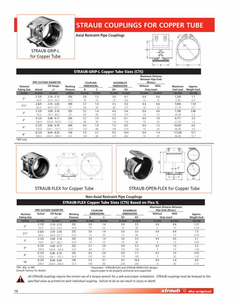
strauB-GriP-L Copper tube sizes (Cts)
nominal Tubing Size
PIPE OUTSIdE dIAMETER
workingPressure
COUPLIng dIMEnSIOns
ASSEMBLEd dIMEnSIOnS
Maximum distance Between Pipe Ends
(Rmax.)
MaximumEnd Load
Approx. weight Each
Od Range without withActual +/- B C dv kv Strip insert
Inches In./mm In./mm psi/bar In./mm In./mm In./mm In./mm In./mm In./mm Lbs./kN Lbs./kg
�"�.1�� �.10 - �.1� ��0 �.0 1.� �.0 �.1 0.� 0.� 1,��9 1.154.0 53.5 - 54.5 17.2 76 37 75 105 10 15 5.90 0.5
�1⁄�"�.��� �.�� - �.�� �90 �.7 1.� �.� �.0 0.� 0.� 7,000 1.��66.6 64.9 - 67.3 27 94 36 89 127 10 15 31.10 0.7
�"�.1�� �.09 - �.1� ��� �.7 1.� �.0 �.� 0.� 0.� 7,700 �.��79.4 78.7 - 80.3 23 94 36 102 137 10 15 34.30 1.3
�"�.1�� �.0� - �.17 ��0 �.7 1.� �.� �.1 0.� 1.0 �,771 �.�104.8 103.8 - 105.8 17.2 94 36 135 155 10 25 21.20 1.5
�"�.1�� �.0� - �.19 �00 �.� 1.9 7.� �.� 0.� 1.� 10,��1 �.�155.6 154.1 - 157.1 13.8 110 48 185 210 10 30 46.00 3.0
�"�.1�� �.0� - �.�0 100 �.� �.1 9.� 10.� 0.� 1.� 17,��� 1�.1206.4 204.4 - 208.4 6.9 140 80 235 264 10 35 56.80 12.1
strauB-FLeX Copper tube sizes (Cts) Based on Flex iL
nominal Tubing Size
PIPE OUTSIdE dIAMETER
workingPressure
COUPLIng dIMEnSIOns
ASSEMBLEd dIMEnSIOnS
Maximum distance Between Pipe Ends (Rmax.)
Approx. weight Each
Actual Od Range without with+/- B C dv kv Strip insert
Inches In./mm In./mm psi/bar In./mm In./mm In./mm In./mm In./mm In./mm Lbs./kg
�"�.1�� �.10 - �.1� ��� �.0 1.� �.0 �.� 0.� 0.� 1.�154.0 53.5 - 54.5 16.0 75 35 75 90 5 15 0.58
�1⁄�"�.��� �.�� - �.�� ��� �.0 1.� �.0 �.� 0.� 0.� 1.�66.6 64.9 - 67.3 16.0 75 35 75 90 5 15 0.59
�"�.1�� �.09 - �.1� ��� �.0 1.� �.0 �.� 0.� 0.� �.179.4 78.7 - 80.3 16.0 75 35 75 90 5 15 0.95
�"�.1�� �.0� - �.17 ��� �.7 �.0 �.9 �.� 0.� 1.0 �.�104.8 103.8 - 105.8 16.0 94 51 125 140 5 25 1.04
�"�.1�� �.0� - �.19 ��� �.� �.� �.9 7.7 0.� 1.� �.��155.6 154.1 - 157.1 16.0 107 62 175 195 5 35 1.61
*�"�.1�� �.0� - �.�0 1�0 �.� �.1 9.� 10.� 0.� 1.� �.0206.4 204.4 - 208.4 10.3 140 80 235 264 10 35 2.72
STRAUB COUPLIngS FOR COPPER TUBE
STRAUB-GRIP-L for Copper Tube
B
CR
OD
D
KV
V
STRAUB-FLEX for Copper Tube STRAUB-OPEN-FLEX for Copper Tube
CB D
R
V
OD
Axial Restraint Pipe Couplings
non-Axial Restraint Pipe Couplings
All STRAUB couplings require the correct use of a torque wrench for a safe and proper installation. STRAUB couplings must be torqued to the
specified value as printed on each individual coupling. Failure to do so can result in injury or death.
*W� only
*W1, W�, or W� Consult Factory for details
*Important - STRAUB-FLEX and STRAUB-OPEN-FLEX designs require pipes to be properly anchored and supported.
High-Performance Pipe Couplings • 1-877-5-STRAUB 17
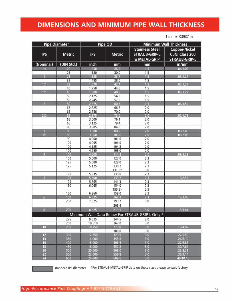
dIMEnSIOnS And MInIMUM PIPE wALL ThICknESS
Pipe diameter Pipe Od Minimum wall Thickness
IPS Metric IPS MetricStainless Steel STRAUB-gRIP-L & METAL-gRIP
Copper-nickel Cuni Class 200 STRAUB-gRIP-L
(nominal) (dIn Std.) inch mm mm in/mm �⁄� �0 1.0�0 ��.9 1.� .0�/1.0�
�� 1.1�0 �0.0 1.�1 �� 1.��� ��.7 1.� .0�/1.�7
�� 1.�9� ��.0 1.�11⁄� �� 1.�70 ��.� 1.� .0�/1.�7
�0 1.7�0 ��.� 1.�11⁄� �0 1.900 ��.� 1.� .0�/1.�7
�0 �.1�� ��.0 1.��0 �.��� �7.0 1.�
� �0 �.�7� �0.� 1.� .0�/1.���� �.��� ��.� �.0�� �.7�� 70.0 �.0
�1⁄� �� �.�7� 7�.0 �.0 .07/1.7��� �.000 7�.1 �.0
�� �.1�� 79.� �.0�0 �.�0� ��.0 �.0
� �0 �.�00 ��.9 �.0 .0�/�.0��1⁄� �0 �.9�0 100.� �.0 .0�/�.0�
90 �.000 101.� �.0 100 �.09� 10�.0 �.0 100 �.1�� 10�.� �.0
100 �.��0 10�.0 �.0� 100 �.�00 11�.� �.0 .09/�.�9
100 �.000 1�7.0 �.�1�� �.0�0 1�9.0 �.�1�� �.1�� 1�0.� �.�
1�1.0* �.01�� �.��� 1��.0 �.�
� 1�� �.�00 1�9.7 �.� .10/�.��1�� �.��� 1�1.� �.�1�0 �.0�� 1��.0 �.�
1��.�* �.�1�0 �.��0 1�9.0 �.�
� 1�0 �.��� 1��.� �.� .1�/�.0��00 7.��� 19�.7 �.0
�0�.�� �00 �.��� �19.1 �.0 .1�/�.�1
Minimum Wall Data Below For STRAUB-GRIP-L Only * ��� 9.��� ���.� �.0
��0 10.�10 ��7.0 �.010 ��0 10.7�0 �7�.0 �.0 .19/�.��
�0�.0 �.01� �00 1�.7�0 ���.9 �.0 .��/�.�01� ��0 1�.000 ���.� �.0 .��/�.101� �00 1�.000 �0�.� �.0 .�7/�.��1� ��0 1�.000 ��7.� �.0 .�0/7.���0 �00 �0.000 �0�.0 �.0 .��/�.���� ��0 ��.000 ���.� �.0 .��/9.1��� �00 ��.000 �09.� �.0 .�0/10.1�
standard IPS diameter
1 mm = .0�9�7 in
*For STRAUB-METAL-GRIP data on these sizes please consult factory.
1�
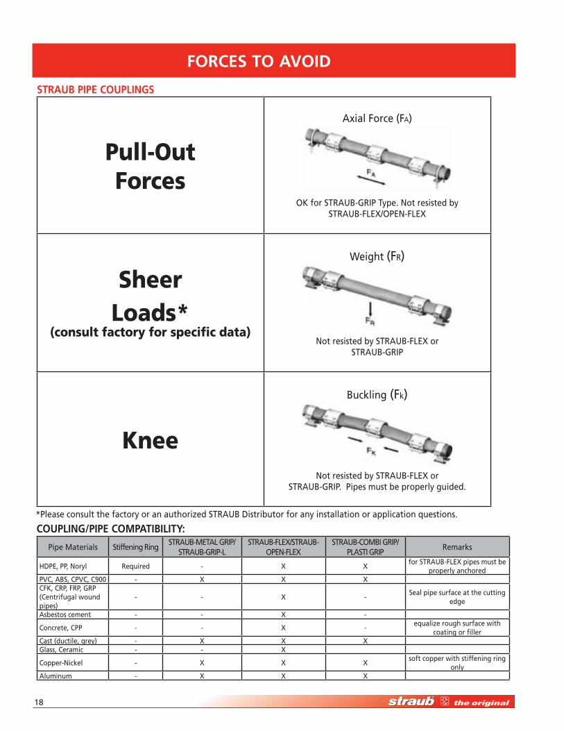
Pipe Materials Stiffening RingSTRAUB-METAL GRIP/
STRAUB-GRIP-LSTRAUB-FLEX/STRAUB-
OPEN-FLEXSTRAUB-COMBI GRIP/
PLASTI GRIPRemarks
HDPE, PP, Noryl Required - X Xfor STRAUB-FLEX pipes must be
properly anchoredPVC, ABS, CPVC, C900 - X X XCFK, CRP, FRP, GRP (Centrifugal wound pipes)
- - X -Seal pipe surface at the cutting
edge
Asbestos cement - - X -
Concrete, CPP - - X -equalize rough surface with
coating or fillerCast (ductile, grey) - X X XGlass, Ceramic - - X
Copper-Nickel - X X Xsoft copper with stiffening ring
onlyAluminum - X X X
COUPLIng/PIPE COMPATIBILITy:
FORCES TO AvOId
Pull-Out Forces
Axial Force (FA)
OK for STRAUB-GRIP Type. Not resisted by STRAUB-FLEX/OPEN-FLEX
sheer Loads*
(consult factory for specific data)
Weight (FR)
Not resisted by STRAUB-FLEX or STRAUB-GRIP
Knee
Buckling (Fk)
Not resisted by STRAUB-FLEX or STRAUB-GRIP. Pipes must be properly guided.
STRAUB PIPE COUPLIngS
*Please consult the factory or an authorized STRAUB Distributor for any installation or application questions.
High-Performance Pipe Couplings • 1-877-5-STRAUB 19
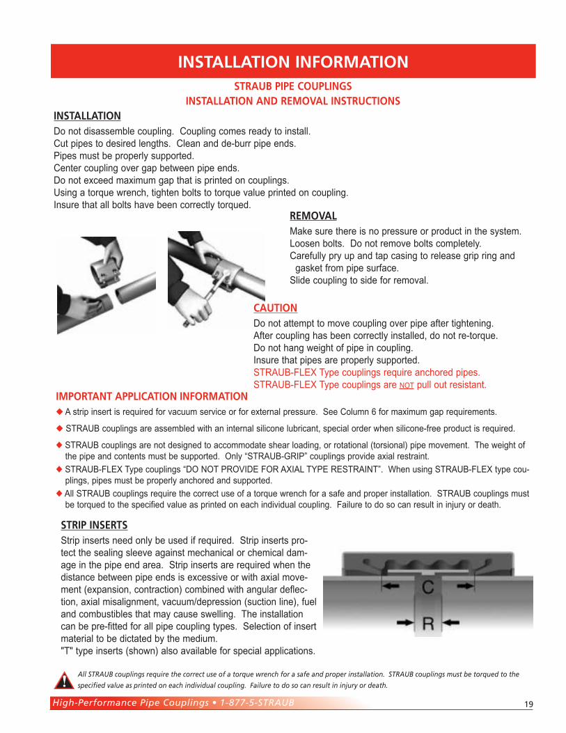
InSTALLATIOn InFORMATIOn
STRIP InSERTSStrip inserts need only be used if required. Strip inserts pro-tect the sealing sleeve against mechanical or chemical dam-age in the pipe end area. Strip inserts are required when the distance between pipe ends is excessive or with axial move-ment (expansion, contraction) combined with angular deflec-tion, axial misalignment, vacuum/depression (suction line), fuel and combustibles that may cause swelling. The installation can be pre-fitted for all pipe coupling types. Selection of insert material to be dictated by the medium. "T" type inserts (shown) also available for special applications.
STRAUB PIPE COUPLIngS InSTALLATIOn And REMOvAL InSTRUCTIOnS
InSTALLATIOnDo not disassemble coupling. Coupling comes ready to install. Cut pipes to desired lengths. Clean and de-burr pipe ends. Pipes must be properly supported. Center coupling over gap between pipe ends. Do not exceed maximum gap that is printed on couplings. Using a torque wrench, tighten bolts to torque value printed on coupling.Insure that all bolts have been correctly torqued.
REMOvALMake sure there is no pressure or product in the system. Loosen bolts. Do not remove bolts completely. Carefully pry up and tap casing to release grip ring and gasket from pipe surface. Slide coupling to side for removal.
CAUTIOnDo not attempt to move coupling over pipe after tightening. After coupling has been correctly installed, do not re-torque. Do not hang weight of pipe in coupling. Insure that pipes are properly supported. STRAUB-FLEX Type couplings require anchored pipes. STRAUB-FLEX Type couplings are not pull out resistant.
All STRAUB couplings require the correct use of a torque wrench for a safe and proper installation. STRAUB couplings must be torqued to the
specified value as printed on each individual coupling. Failure to do so can result in injury or death.
IMPORTAnT APPLICATIOn InFORMATIOn A strip insert is required for vacuum service or for external pressure. See Column 6 for maximum gap requirements.
STRAUB couplings are assembled with an internal silicone lubricant, special order when silicone-free product is required.
STRAUB couplings are not designed to accommodate shear loading, or rotational (torsional) pipe movement. The weight of the pipe and contents must be supported. Only “STRAUB-GRIP” couplings provide axial restraint.
STRAUB-FLEX Type couplings “DO NOT PROVIDE FOR AXIAL TYPE RESTRAINT”. When using STRAUB-FLEX type cou-plings, pipes must be properly anchored and supported.
All STRAUB couplings require the correct use of a torque wrench for a safe and proper installation. STRAUB couplings must be torqued to the specified value as printed on each individual coupling. Failure to do so can result in injury or death.
�0
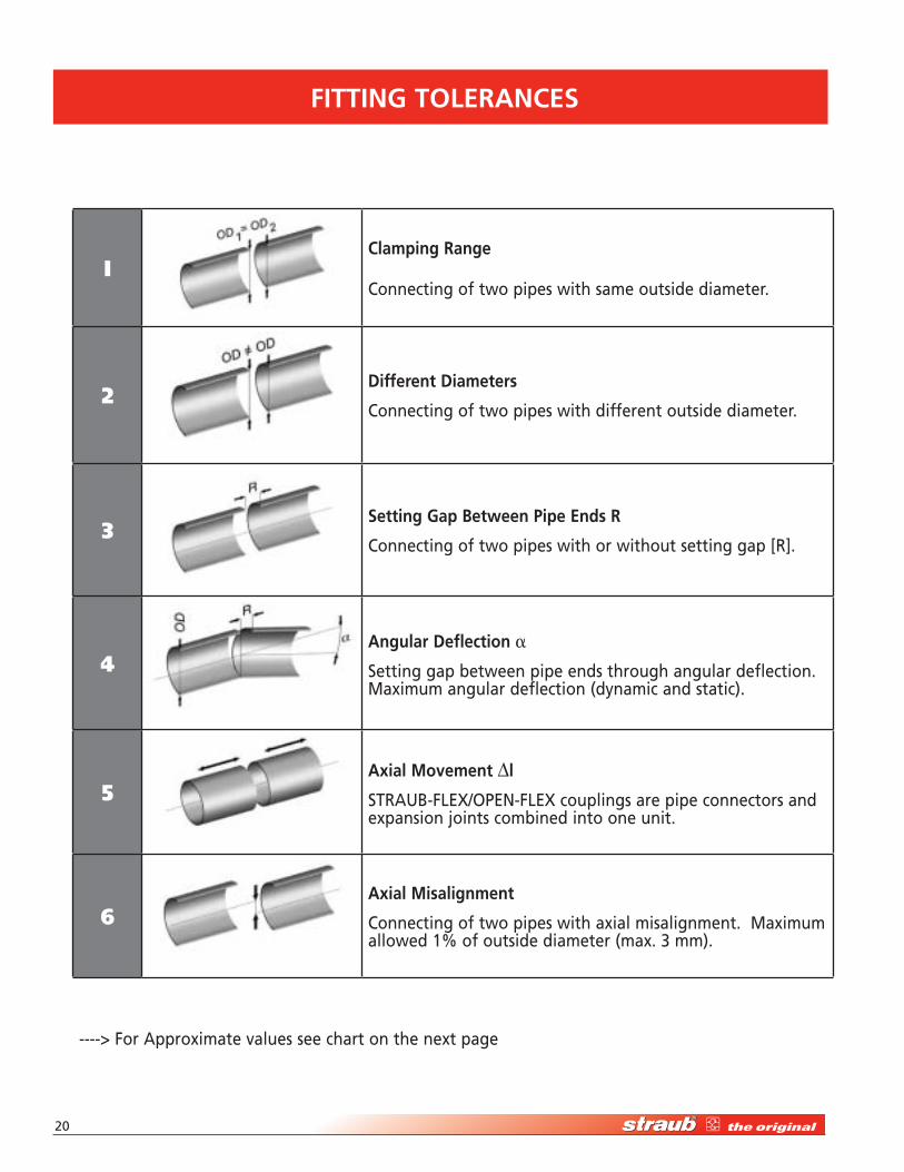
FITTIng TOLERAnCES
IClamping Range
Connecting of two pipes with same outside diameter.
2different diameters
Connecting of two pipes with different outside diameter.
3Setting gap Between Pipe Ends R
Connecting of two pipes with or without setting gap [R].
4Angular deflection a
Setting gap between pipe ends through angular deflection. Maximum angular deflection (dynamic and static).
5Axial MovementDl
STRAUB-FLEX/OPEN-FLEX couplings are pipe connectors and expansion joints combined into one unit.
6Axial Misalignment
Connecting of two pipes with axial misalignment. Maximum allowed 1% of outside diameter (max. � mm).
----> For Approximate values see chart on the next page
High-Performance Pipe Couplings • 1-877-5-STRAUB �1
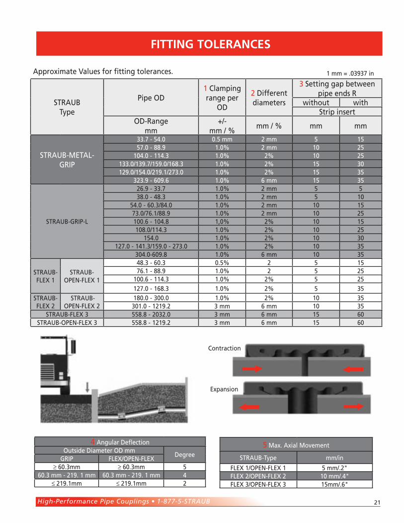
FITTIng TOLERAnCES
STRAUB Type
Pipe OD1 Clamping range per
OD
� Different diameters
� Setting gap between pipe ends R
without withStrip insert
OD-Range mm
+/- mm / %
mm / % mm mm
STRAUB-METAL-GRIP
��.7 - ��.0 0.� mm � mm � 1��7.0 - ��.9 1.0% � mm 10 ��
10�.0 - 11�.� 1.0% �% 10 ��1��.0/1�9.7/1�9.0/1��.� 1.0% �% 1� �01�9.0/1��.0/�19.1/�7�.0 1.0% �% 1� ��
���.9 - �09.� 1.0% � mm 1� ��
STRAUB-GRIP-L
��.9 - ��.7 1.0% � mm � ���.0 - ��.� 1.0% � mm � 10
��.0 - �0.�/��.0 1.0% � mm 10 1�7�.0/7�.1/��.9 1.0% � mm 10 ��100.� - 10�.� 1,0% �% 10 1�10�.0/11�.� 1.0% �% 10 ��
1��.0 1.0% �% 10 �01�7.0 - 1�1.�/1�9.0 - �7�.0 1.0% �% 10 ��
�0�.0-�09.� 1.0% � mm 10 ��
STRAUB-FLEX 1
STRAUB-OPEN-FLEX 1
��.� - �0.� 0.�% � � 1�7�.1 - ��.9 1.0% � � ��
100.� - 11�.� 1.0% �% � ��1�7.0 - 1��.� 1.0% �% � ��
STRAUB-FLEX �
STRAUB-OPEN-FLEX �
1�0.0 - �00.0 1.0% �% 10 ���01.0 - 1�19.� � mm � mm 10 ��
STRAUB-FLEX � ���.� - �0��.0 � mm � mm 1� �0STRAUB-OPEN-FLEX � ���.� - 1�19.� � mm � mm 1� �0
Approximate Values for fitting tolerances.
� Angular DeflectionOutside Diameter OD mm
DegreeGRIP FLEX/OPEN-FLEX
≥ �0.�mm ≥ �0.�mm ��0.� mm - �19. 1 mm �0.� mm - �19. 1 mm �
≤ �19.1mm ≤ �19.1mm �
� Max. Axial Movement
STRAUB-Type mm/in
FLEX 1/OPEN-FLEX 1 � mm/.�"FLEX �/OPEN-FLEX � 10 mm/.�"FLEX �/OPEN-FLEX � 1�mm/.�"
Contraction
Expansion
1 mm = .0�9�7 in
��
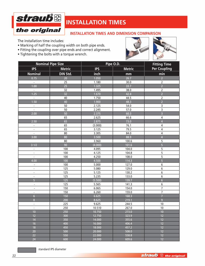
InSTALLATIOn TIMES
nominal Pipe Size Pipe O.d. Fitting Time Per CouplingIPS Metric IPS Metric
nominal dIn Std. inch mm min0.7� �0 1.0�0 ��.7 �
- �� 1.1�0 �0.0 �1.00 �� 1.��� ��.7 �
- �� 1.�9� ��.0 �1.�� �� 1.�70 ��.� �
- �0 1.7�0 ��.� �1.�0 �0 1.900 ��.� �
- �0 �.1�� ��.0 �- �0 �.��� �7.0 �
�.00 �0 �.�7� �0.� ��� �.��� ��.� �
�.�0 �� �.�7� 7�.0 �- �� (�.000) 7�.1 �- �� �.1�� 79.� �- �0 �.�0� ��.0 �
�.00 �0 �.�00 ��.9 ��0 �.9�0 100.� �
� 1/� 90 (�.000) 101.� �- 100 �.09� 10�.0 �- 100 �.1�� 10�.� �- 100 �.��0 10�.0 �
�.00 100 �.�00 11�.� � - 100 �.000 1�7.0 �- 1�� �.0�0 1�9.0 �- 1�� �.1�� 1�0.� �- 1�� �.��� 1��.0 �� 1�� (�.�00) 1�9.7 � - 1�� �.��� 1�1.� � - 1�0 �.0�� 1��.0 7- 1�0 �.��0 1�9.0 7� 1�0 �.��� 1��.� 7� �00 �.��� �19.1 9- ��� 9.��� ���.� 10- ��0 10.�10 ��7.0 10
10 ��0 10.7�0 �7�.0 101� �00 1�.7�0 ���.9 1�1� ��0 1�.000 ���.� 1�1� �00 1�.000 �0�.� 1�1� ��0 1�.000 ��7.� 1��0 �00 �0.000 �0�.0 1��� ��0 ��.000 ���.� 1��� �00 ��.000 �09.� 1�
standard IPS diameter
InSTALLATIOn TIMES And dIMEnSIOn COMPARISOn
The installation time includes:• Marking of half the coupling width on both pipe ends.• Fitting the coupling over pipe ends and correct alignment.• Tightening the bolts with a torque wrench.
High-Performance Pipe Couplings • 1-877-5-STRAUB ��
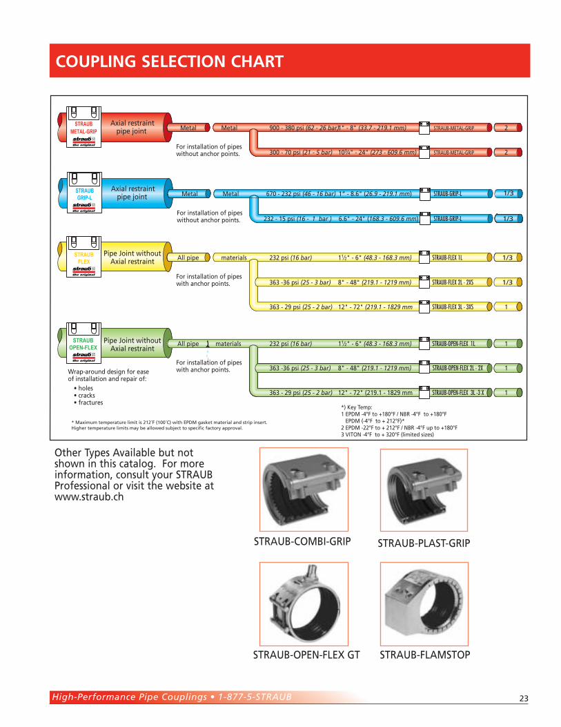
COUPLIng SELECTIOn ChART
PlasticSTRAUB
FLEX
STRAUBOPEN-FLEX
STRAUBMETAL-GRIP
For installation of pipeswithout anchor points.
For installation of pipeswith anchor points.
For installation of pipeswith anchor points.
Axial restraintpipe joint
Pipe Joint withoutAxial restraint
Pipe Joint withoutAxial restraint
Wrap-around design for easeof installation and repair of:
• holes• cracks• fractures
STRAUB-METAL-GRIP
STRAUB-METAL-GRIP
STRAUB-FLEX 1L
STRAUB-FLEX 2L - 2XS
STRAUB-FLEX 3L - 3XS
STRAUB-OPEN-FLEX 1L
STRAUB-OPEN-FLEX 2L - 2X
STRAUB-OPEN-FLEX 3L -3 X
900 - 380 psi (62 - 26 bar)1" - 8" (33.7 - 219.1 mm)
300 - 70 psi (21 - 5 bar) 103⁄4" - 24" (273 - 609.6 mm)
232 psi (16 bar) 11⁄2" - 6" (48.3 - 168.3 mm)
363 -36 psi (25 - 3 bar) 8" - 48" (219.1 - 1219 mm)
363 - 29 psi (25 - 2 bar) 12" - 72" (219.1 - 1829 mm
232 psi (16 bar) 11⁄2" - 6" (48.3 - 168.3 mm)
363 -36 psi (25 - 3 bar) 8" - 48" (219.1 - 1219 mm)
363 - 29 psi (25 - 2 bar) 12" - 72" (219.1 - 1829 mm
*) Key Temp:1 EPDM -4°F to +180°F / NBR -4°F to +180°F EPDM (-4°F to + 212°F)*2 EPDM -22°F to + 212°F / NBR -4°F up to +180°F3 VITON -4°F to + 320°F (limited sizes)
2
2
1/3
1/3
1
1
1
1
Metal Metal
All pipe materials
All pipe materials
STRAUBGRIP-L
For installation of pipeswithout anchor points.
Axial restraintpipe joint Metal STRAUB-GRIP-L
STRAUB-GRIP-L
670 - 232 psi (46 - 16 bar) 1“ - 8.6" (26.9 - 219.1 mm)
232 - 15 psi (16 - 1 bar ) 6.6" - 24" (168.3 - 609.6 mm) 1/3
Metal 1/3
* Maximum temperature limit is 212˚F (100˚C) with EPDM gasket material and strip insert.Higher temperature limits may be allowed subject to specific factory approval.
STRAUB-PLAST-GRIPSTRAUB-COMBI-GRIP
STRAUB-OPEN-FLEX GT STRAUB-FLAMSTOP
Other Types Available but not shown in this catalog. For more information, consult your STRAUB Professional or visit the website at www.straub.ch
DISTRIBUTED BY
#7� / Printed in USA / ULitho / 9.0� / �.�M / ©�00�
Marketing: USAInterwest Sales
P.O. Box �0� • National City, CA 919�1Tel: 1-�77-�-STRAUB (7�7���)
Fax: (�19)-���-0���E-mail: [email protected]
Web site: www.straub-couplings.com
STRAUB werke A.g.Rohrverbindungen • Straubstrasse 1�
7��� Wangs, SwitzerlandTel: +�1 �1-7��-�100 Fax: +�1 �1-7��-�101
E-mail: [email protected] site: www.straub.ch
The materials and data in this catalogue are intended to assist the user in the proper selection of STRAUB Coupling products. STRAUB Pipe Couplings assumes no responsibility for any damage that might occur as a result of the use of any data, charts or application examples contained herein. All the information contained in this catalogue is subject to change by STRAUB Pipe Couplings without notice as a result of product re-designs, product improvements or other reasons.
STRAUB Pipe Couplings are designed for use under circumstances in which human life is potentially at risk. When considering the use of any product contained herein for special applications, please contact, STRAUB Werke A.G., Switzerland, or an authorized STRAUB distributor.
LIABILITy dISCLAIMER
The information contained herein may include inaccuracies or typographical errors. In addition, changes are periodically made to this information. STRAUB may make such changes to this information at any time without notice to the user.
STRAUB Pipe Couplings makes no representations about the suitability of the information contained herein for any purpose. All such information is provided as is without warranty of any kind. STRAUB Pipe Couplings disclaims all warranties with regard to this information. Under no circumstances shall STRAUB Pipe Couplings be liable for any direct, indirect, punitive, incidental, special or consequential damages arising out of or connected with the use of this information, whether based on contract, tort, strict liability or otherwise, even if STRAUB Pipe Couplings has been advised of the possibility of damages.
Marketing/Manufacturing Canada Straub Tadco Inc.1��9 Aerowood Drive • Mississauga
ON • L�W 1B9Tel:90�.��9.911�Fax: 90�.��9.911�
E-Mail: [email protected] Site: www.straubcouplings.com