Embed Size (px)
Citation preview
Stream-Gaging Stations For Research on Small
Watersheds
U.S. DEPARTMENT OF AGRICULTURE AGRICULTURE HANDBOOK NO. 268
FOREST SERVICE MAY 1964

Stream-Gaging Stations For Research on Small
Watersheds
Kenneth G. Reinhart and Robert S. Pierce
Northeastern Forest Experiment Station
Forest Service, U.S. Department of Agriculture
AGRICULTURE HANDBOOK NO. 268 MAY 1964

Contents Page
Introduction 1 Choosing the stream-gaging site 2 Types of stream-gaging stations 3
Weirs 3 Flumes 8
Choosing the stream-gaging station design 10 A sharp-crested 120° V-notch weir 12
Design 13 Cutoff wall 13 Watertight box 15
Construction 15 Layout 15 Excavation 16 Cutoff wall 16 Sidewalls 19 Floor 20 Weir blade 20 Drainpipes 21 Debris dam and baffles 21 Gagehouse and well 22 Intake pipes 23 Cost of construction 24
Instrumentation 24 Water-level recorder 24 Hook gage 25 Reference tape 25 Staff and crest gages 26
Operating procedures and maintenance 27 Rating the weir 27 Periodic chart changing 28 Checking water levels 28 Instrument and basin 28 Trash screens 28
Cold weather maintenance 29 Enclosure of well 29 Subfloor 29 Oil cyhnder 29 Heating appliances 29 Ice in the weir basin 30
Bibliography 31 Appendix 33
For sale by the Superintendent of Documents, U.S. Government Printing Office Washington, D.C., 20402-Price 30 cents.

Introduction With an increasing population and per-
capita consumption of water, nationwide concern has arisen about the adequacy of our water supplies. Some regions suffer acute shortages. Yet many areas sometimes sustain major damage from great floods.
Watershed research has shown that land use and treatment affect both water yield and peak flows. Under certain situations yield may be increased by vegetation man- agement and other land practices; in other circumstances, peak flows may be reduced. This research is just being started in some parts of the country.
One of the accepted research techniques in watershed management is the measurement of streamflow from small experimental watersheds. Such measurement permits evaluation of the effect that manipulation of cover has on water-yield characteristics for fairly homogeneous areas.
During the past several years (since 1955), the authors have been responsible, or have had close contact with those responsible, for building 21 stream-gaging stations in small experimental watersheds in the North- east, particularly on the Fernow Experi- mental Forest in West Virginia and the Hubbard Brook Experimental Forest in New Hampshire. This experience, a review of the literature, and information from several other workers in the field provide the basis for this handbook. It is prepared especially for researchers who have little experience in water measurement but are responsible for the construction and operation of stream- gaging stations.
Details of all aspects of stream gaging will not be discussed. This report is only a gen- eral guide on the design and construction of small stream-gaging stations. Additional details should be sought from the literature and from geologists, engineers, and hydraulic experts.
Stream gaging, as used here, is the measure- ment of the water leaving a watershed as flow in a natural stream channel. Water lost to deep seepage and not appearing as stream- flow at the point of measurement cannot be measured by the stream-gaging station. Therefore, watersheds with minimum deep seepage are best for research.
Small watersheds include those of about 20 to 1,500 acres. Such watersheds are large enough —in the Northeast at least —to pro- vide flow all or most of the time, but they
are small enough so that construction of an artificial control is not impractical. On larger streams, gaging is usually done by using natural controls; such measurement is generally less precise than that with arti- ficial controls on smaller streams.
A control is a natural constriction of the channel, a long reach of the channel, a stretch of rapids, or an artificial structure downstream from a gaging station that de- termines the stage-discharge relation at the gage (Langbein and Iseri 1960).^
There are many objectives of stream gag- ing in watershed research. In some cases one objective may be paramount; in others several may be about equally important.
A common objective is a continuous record of streamflow. To attain this goal, recording instruments that give a round-the-clock rec- ord are required. Usually yearlong records are obtained, but records for the growing season or some other short period may suffice. Measurements may be made to de- termine maximum flows and runoff" volumes for major storm periods, low flows, or all flow leaving the watershed.
The research program will specify the num- ber of stream-gaging stations required. Ordinarily two or more watersheds, as nearly identical as possible, are chosen. This per- mits the development during the pretreat- ment period of an expression for predicting flow of one watershed from that of the other; after treating one of the watersheds, differ- ences between predicted and measured flow indicate the effect of treatment.
Sometimes only one watershed is used, and flows before and after treatment are com- pared to determine treatment effects. In this case, equations for predicting flow must be developed from climatic measurements in the calibration period.^ Comparison through a control watershed partly counteracts the difficulties experienced because of differences in climate from year to year or before and after treatment (Reinhart 1958).
In this handbook, the types of gaging sta- tions with which the authors have had per- sonal experience will be discussed in some detail. Other types of stations will be con- sidered in a more general way to provide an overall treatment of the subject.
^ Names and dates in parentheses refer to Bibliog- raphy, p. 31.
2 Reigner, Irvin C. CaUbrating a watershed by using chmatic data. U.S. Forest Serv. Res. Paper NE-15, 45 pp., illus. Northeast. Forest Expt. Sta., Upper Darby, Pa. 1964.
Choosing the Stream-Gaging Site
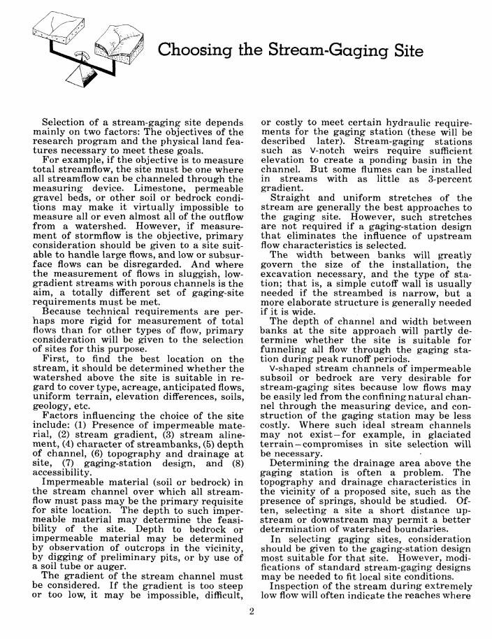
Selection of a stream-gaging site depends mainly on two factors: The objectives of the research program and the physical land fea- tures necessary to meet these goals.
For example, if the objective is to measure total streamflow, the site must be one where all streamflow can be channeled through the measuring device. Limestone, permeable gravel beds, or other soil or bedrock condi- tions may make it virtually impossible to measure all or even almost all of the outflow from a watershed. However, if measure- ment of stormflow is the objective, primary consideration should be given to a site suit- able to handle large flows, and low or subsur- face flows can be disregarded. And where the measurement of flows in sluggish, low- gradient streams with porous channels is the aim, a totally different set of gaging-site requirements must be met.
Because technical requirements are per- haps more rigid for measurement of total flows than for other types of flow, primary consideration will be given to the selection of sites for this purpose.
First, to find the best location on the stream, it should be determined whether the watershed above the site is suitable in re- gard to cover type, acreage, anticipated flows, uniform terrain, elevation differences, soils, geology, etc.
Factors influencing the choice of the site include: (1) Presence of impermeable mate- rial, (2) stream gradient, (3) stream aline- ment, (4) character of streambanks, (5) depth of channel, (6) topography and drainage at site, (7) gaging-station design, and (8) accessibility.
Impermeable material (soil or bedrock) in the stream channel over which all stream- flow must pass may be the primary requisite for site location. The depth to such imper- meable material may determine the feasi- bility of the site. Depth to bedrock or impermeable material may be determined by observation of outcrops in the vicinity, by digging of preliminary pits, or by use of a soil tube or auger.
The gradient of the stream channel must be considered. If the gradient is too steep or too low, it may be impossible, difficult,
or costly to meet certain hydraulic require- ments for the gaging station (these will be described later). Stream-gaging stations such as V-notch weirs require sufficient elevation to create a ponding basin in the channel. But some flumes can be installed in streams with as little as 3-percent gradient.
Straight and uniform stretches of the stream are generally the best approaches to the gaging site. However, such stretches are not required if a gaging-station design that eliminates the influence of upstream flow characteristics is selected.
The width between banks will greatly govern the size of the installation, the excavation necessary, and the type of sta- tion; that is, a simple cutoff wall is usually needed if the streambed is narrow, but a more elaborate structure is generally needed if it is wide.
The depth of channel and width between banks at the site approach will partly de- termine whether the site is suitable for funneling all flow through the gaging sta- tion during peak runoff periods.
V-shaped stream channels of impermeable subsoil or bedrock are very desirable for stream-gaging sites because low flows may be easily led from the confining natural chan- nel through the measuring device, and con- struction of the gaging station may be less costly. Where such ideal stream channels may not exist —for example, in glaciated terrain —compromises in site selection will be necessary.
Determining the drainage area above the gaging station is often a problem. The topography and drainage characteristics in the vicinity of a proposed site, such as the presence of springs, should be studied. Of- ten, selecting a site a short distance up- stream or downstream may permit a better determination of watershed boundaries.
In selecting gaging sites, consideration should be given to the gaging-station design most suitable for that site. However, modi- fications of standard stream-gaging designs may be needed to fit local site conditions.
Inspection of the stream during extremely low flow will often indicate the reaches where

flow is restricted to the surface because of soil or geologic conditions and those where flow is below the surface. The stream should be inspected during high-flow periods to esti- mate maximum discharge and to see if the banks at the site can carry the flow.
An additional consideration is accessibility.
Gaging sites that meet the technical require- ments may be impractical because of exces- sive traveltime to the site, difficulty of hauling in construction materials and equip- ment, lack of workspace, and inaccessibility in certain seasons.
Types of Stream-Gaging Stations
The basic components of a stream-gaging station are the control and the water-stage recorder. The control and the volume of flow determine the elevation of the water surface at the recorder location. The relation be- tween height of the water at the gaging point and rate of flow over the control is called the stage-discharge relationship or rating. Generally artificial controls are used for research on small watersheds, so only those controls will be considered in this handbook.
For most measurements, the control must be constructed so that nearly all outflow from the watershed goes over it; flow under it or around it will escape measurement.
The most common types of stream-gaging stations are weirs and flumes. With weirs, water is ponded above the control, and changes in the elevation are related to dis- charge. Weirs have often been preferred for gaging of small watersheds. The weir, when properly set and maintained, is considered one of the most accurate means of measuring flowing water (Parshall 1950). Where heavy sediment-laden flows are common, particu- larly as bedload movement, flumes should be used; a flume is a stabilized channel (without an impoundment) with access to a stilhng well. Flumes also must be used where the gradient of the stream is particularly low.
The various objectives for which stream- gaging stations have been built, and the re- lated conditions, have resulted in many different types of weirs and flumes.
Weirs or flumes are constructed of various materials. Concrete, because of its strength and permanence, probably is used the most. Treated wood, concrete blocks, metal, and many other materials are also used. The
weir notch is often a steel blade set into con- crete, and flumes are often lined with steel for permanence.
WEIRS
Weir may denote a notch of regular form (rectangular, triangular, trapezoidal, circu- lar, or parabolic) through which water flows, or it may mean the structure containing the notch. As used in this handbook, weir in- cludes all components of a stream-gaging station that incorporates a notch control.
An impoundment of water (the weir basin) is formed upstream from the wall or dam con- taining the notch. A stilling well with water-level recorder is connected to the weir basin. A gagehouse or some other type of shelter is provided to protect the recorder.
The cutoff wall or dam is used to divert through the notch all water (above or below the streambed) moving down the channel. Where possible, the cutoff wall is tied into bedrock or other impermeable material so that no water can flow under or around it. But where leakage is apt to occur the weir basin is sometimes constructed as a water- tight box (see p. 15).
The edge or surface over which the water flows is called the crest. Weirs can be either sharp crested or broad crested. A sharp- crested weir has a blade with a sharp up- stream edge so that the passing water touches only a thin edge and springs clear of the rest of the crest. The blades of the 90° and 120° V-notch weirs installed by the au- thors are of M-inch angle iron or ^-inch
steelplate ground to a sharp edge at a 45- degree-angle.
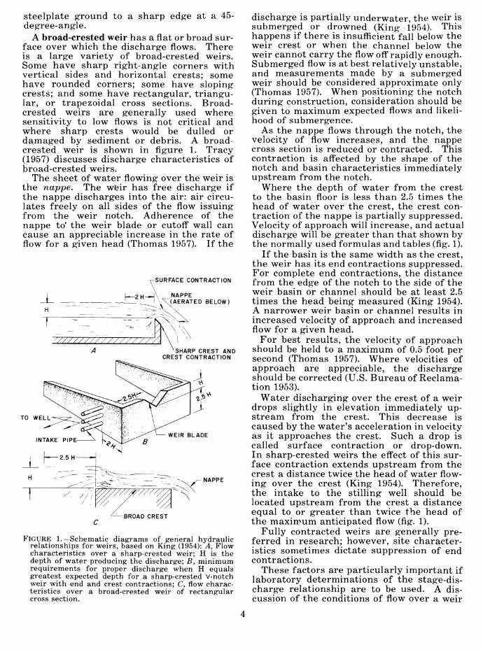
A broad-crested weir has a flat or broad sur- face over which the discharge flows. There is a large variety of broad-crested weirs. Some have sharp right-angle corners with vertical sides and horizontal crests; some have rounded corners; some have sloping crests; and some have rectangular, triangu- lar, or trapezoidal cross sections. Broad- crested weirs are generally used where sensitivity to low flows is not critical and where sharp crests would be dulled or damaged by sediment or debris. A broad- crested weir is shown in figure 1. Tracy (1957) discusses discharge characteristics of broad-crested weirs.
The sheet of water flowing over the weir is the nappe. The weir has free discharge if the nappe discharges into the air: air circu- lates freely on all sides of the flow issuing from the weir notch. Adherence of the nappe to' the weir blade or cutoif wall can cause an appreciable increase in the rate of flow for a given head (Thomas 1957). If the
SURFACE CONTRACTION
\ , I \X(AERATED BELOW)
SHARP CREST AND CREST CONTRACTION
NAPPE
BROAD CREST
FIGURE 1. —Schematic diagrams of general hydraulic relationships for weirs, based on King (1954): A, Flow characteristics over a sharp-crested weir; H is the depth of water producing the discharge; B, minimum requirements for proper discharge when H equals greatest expected depth for a sharp-crested V-notch weir with end and crest contractions; C, flow charac- teristics over a broad-crested weir of rectangular cross section.
discharge is partially underwater, the weir is submerged or drowned (King 1954). This happens if there is insufficient fall below the weir crest or when the channel below the weir cannot carry the flow off rapidly enough. Submerged flow is at best relatively unstable, and measurements made by a submerged weir should be considered approximate only (Thomas 1957). When positioning the notch during construction, consideration should be given to maximum expected flows and likeli- hood of submergence.
As the nappe flows through the notch, the velocity of flow increases, and the nappe cross section is reduced or contracted. This contraction is aff'ected by the shape of the notch and basin characteristics immediately upstream from the notch.
Where the depth of water from the crest to the basin floor is less than 2.5 times the head of water over the crest, the crest con- traction of the nappe is partially suppressed. Velocity of approach will increase, and actual discharge will be greater than that shown by the normally used formulas and tables (fig. 1).
If the basin is the same width as the crest, the weir has its end contractions suppressed. For complete end contractions, the distance from the edge of the notch to the side of the weir basin or channel should be at least 2.5 times the head being measured (King 1954). A narrower weir basin or channel results in increased velocity of approach and increased flow for a given head.
For best results, the velocity of approach should be held to a maximum of 0.5 foot per second (Thomas 1957). Where velocities of approach are appreciable, the discharge should be corrected (U.S. Bureau of Reclama- tion 1953).
Water discharging over the crest of a weir drops slightly in elevation immediately up- stream from the crest. This decrease is caused by the water's acceleration in velocity as it approaches the crest. Such a drop is called surface contraction or drop-down. In sharp-crested weirs the effect of this sur- face contraction extends upstream from the crest a distance twice the head of water flow- ing over the crest (King 1954). Therefore, the intake to the stilling well should be located upstream from the crest a distance equal to or greater than twice the head of the maximum anticipated flow (fig. 1).
Fully contracted weirs are generally pre- ferred in research; however, site character- istics sometimes dictate suppression of end contractions.
These factors are particularly important if laboratory determinations of the stage-dis- charge relationship are to be used. A dis- cussion of the conditions of flow over a weir

can be found in King's Handbook of Hydrau- lics (1954).
The rectangular weir has vertical sides and a horizontal crest (fig. 2). Its height and width can be varied considerably, depending on the anticipated flow. The ratio of height to width is usually about 1:3 or 1:4. Its major advantage is its capacity to handle large flows. However, the rectangular weir cannot provide for precise measurement of the low flows of small experimental water- sheds—a small increase in head will give a greatly increased discharge. Therefore, small errors in measurement of head pro- duce relatively large errors in discharge.
An example of a broad-crested rectangular weir is the Trenton type of control, developed by the U.S. Geological Survey (Corbett and others 1943).
The trapezoidal weir is similar to the rec- tangular weir. Its sides, of course, are in- clined from the vertical (fig. 3). It has a larger capacity than a rectangular weir of the same crest length; the discharge is ap-
1-440615
FIGURE 2. —A 6-foot rectangular weir with angle-iron knife-edge blade is used on watersheds where flow ranges from 0.70 to 90 cubic feet per second. Coweeta Hydrologie Laboratory, Franklin, N.C.
proximately the sum of discharges from the rectangular and triangular sections.
^^ ^
I - 4öy7J-l
FIGURE 3. —An 8-foot CipoUetti trapezoidal weir with knife-edge blade is used on watersheds of approximately 2,000 acres. Coweeta Hydrologie Laboratory, Franklin, N.C.
The Cipolletti weir is a special trapezoidal weir that does not require a correction for end contractions. Sides are sloped one unit away from the vertical for each four units of rise. The flow (with end contractions) is about equal to the flow of a rectangular weir of equal crest length that has a channel width the same as the crest (weir with end contrac- tions suppressed).
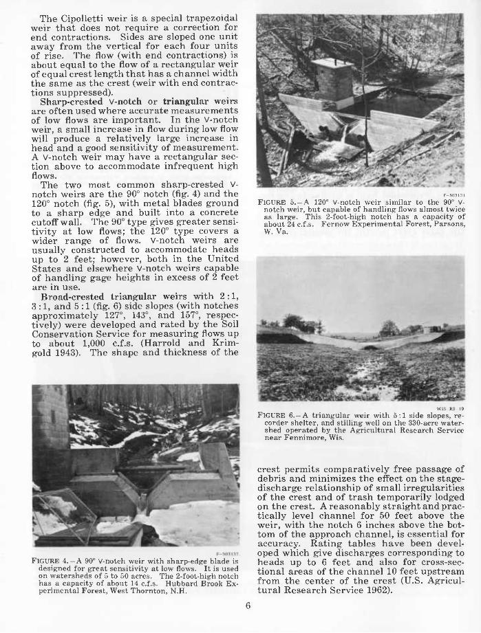
Sharp-crested V-notch or triangular weirs are often used where accurate measurements of low flows are important. In the V-notch weir, a small increase in flow during low flow will produce a relatively large increase in head and a good sensitivity of measurement. A V-notch weir may have a rectangular sec- tion above to accommodate infrequent high flows.
The two most common sharp-crested V- notch weirs are the 90° notch (fig. 4) and the 120° notch (fig. 5), with metal blades ground to a sharp edge and built into a concrete cutoff wall. The 90° type gives greater sensi- tivity at low flows; the 120° type covers a wider range of flows. V-notch weirs are usually constructed to accommodate heads up to 2 feet; however, both in the United States and elsewhere V-notch weirs capable of handling gage heights in excess of 2 feet are in use.
Broad-crested triangular weirs with 2:1, 3:1, and 5 :1 (fig. 6) side slopes (with notches approximately 127°, 143°, and 157°, respec- tively) were developed and rated by the Soil Conservation Service for measuring flows up to about 1,000 c.f.s. (Harrold and Krim- gold 1943). The shape and thickness of the
K-503I3I
FIGURE 5.-A 120° v-notch weir similar to the 90° V- notch weir, but capable of handling flows almost twice as large. This 2-foot-high notch has a capacity of about 24 c.f.s. Fernow Experimental Forest, Parsons, W. Va.
FIGURE 4.-A 90° v-notch weir with sharp-edge blade is designed for great sensitivity at low flows. It is used on watersheds of 5 to 50 acres. The 2-foot-high notch has a capacity of about 14 c.f.s. Hubbard Brook Ex- perimental Forest, West Thornton, N.H.
U1S-R.S-I9 FIGURE 6. —A triangular weir with 5:1 side slopes, re-
corder shelter, and stilling well on the 330-acre water- shed operated by the Agricultural Research Service near Fennimore, Wis.
crest permits comparatively free passage of debris and minimizes the effect on the stage- discharge relationship of small irregularities of the crest and of trash temporarily lodged on the crest. A reasonably straight and prac- tically level channel for 50 feet above the weir, with the notch 6 inches above the bot- tom of the approach channel, is essential for accuracy. Rating tables have been devel- oped which give discharges corresponding to heads up to 6 feet and also for cross-sec- tional areas of the channel 10 feet upstream from the center of the crest (U.S. Agricul- tural Research Service 1962).
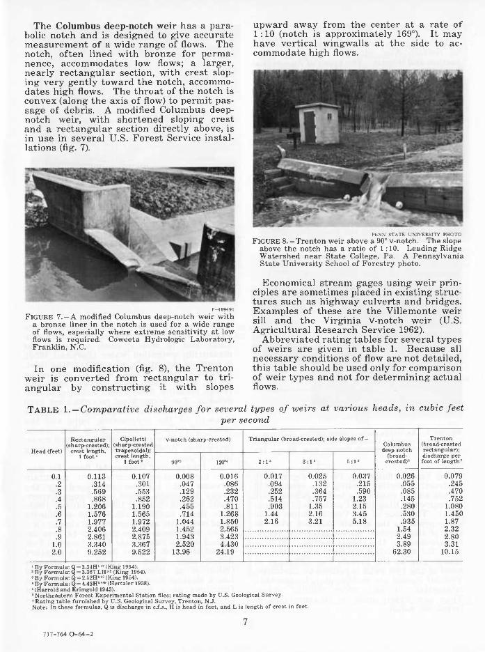
The Columbus deep-notch weir has a para- boHc notch and is designed to give accurate measurement of a wide range of flows. The notch, often lined with bronze for perma- nence, accommodates low flows; a larger, nearly rectangular section, with crest slop- ing very gently toward the notch, accommo- dates high flows. The throat of the notch is convex (along the axis of flow) to permit pas- sage of debris. A modified Columbus deep- notch weir, with shortened sloping crest and a rectangular section directly above, is in use in several U.S. Forest Service instal- lations (fig. 7).
r-469491 FIGURE 7.— A modified Columbus deep-notch weir with
a bronze liner in the notch is used for a wide range of flows, especially where extreme sensitivity at low flows is required. Coweeta Hydrologie Laboratory, Franklin, N.C.
In one modification (fig. 8), the Trenton weir is converted from rectangular to tri- angular by constructing it with slopes
upward away from the center at a rate of 1 :10 (notch is approximately 169°). It may have vertical wingwalls at the side to ac- commodate high flows.
PF.NN STAiK rM\i:Ksri\ PIIOIO FIGURE 8.-Trenton weir above a 90° v-notch. The slope
above the notch has a ratio of 1:10. Leading Ridge Watershed near State College, Pa. A Pennsylvania State University School of Forestry photo.
Economical stream gages using weir prin- ciples are sometimes placed in existing struc- tures such as highway culverts and bridges. Examples of these are the Villemonte weir sill and the Virginia V-notch weir (U.S. Agricultural Research Service 1962).
Abbreviated rating tables for several types of weirs are given in table 1. Because all necessary conditions of flow are not detailed, this table should be used only for comparison of weir types and not for determining actual flows.
TABLE 1.-Comparative discharges for several types of weirs at various heads, in cubic feet per second
Head ffppt)
Rectangular (sharp-crested);
crest length, 1 foot'
Cipolletti (sharp-crested trapezoidal); crest length,
1 foot'
v-notch (sharp-crested) Triangular (broad-crested); side slopes of- Columbus deep notch
(broad- crested)«
Trenton (broad-crested rectangular);
90" 120°' 2:1" 3:1> 5:1' discharge per foot of length'
0.1 0.113 0.107 0.008 0.016 0.017 0.025 0.037 0.026 0.079 .2 .314 .301 .047 .086 .094 .132 .215 .055 .245 .3 .569 .553 .129 .232 .252 .364 .590 .085 .470 .4 .868 .852 .262 .470 .514 .757 1.23 .145 .752 .5 1.206 1.190 .455 .811 .903 1.35 2.15 .280 1.080 .6 1.576 1.565 .714 1.268 1.44 2.16 3.45 .530 1.450 .7 1.977 1.972 1.044 1.850 2.16 3.21 5.18 .935 1.87 .8 2.406 2.409 1.452 2.565 1.54 2.32 .9 2.861 2.875 1.943 3.423 2.49 2.80
1.0 3.340 3.367 2.520 4.430 3.89 3.31 2 0 9.252 9.522 13.96 24.19 62.30 10.15
■ By Formula: Q = 3.34H' " (King 1954). ' By Formula: Q = 3.367 LH« (King 1954). » By Formula: Q = 2.52H' " (King 1954). • By Formula: Q = 4.43H' "• (Hertzler 1938). ' (Harrold and Krimgold 1943). «Northeastern Forest Experimental Station files; rating made by U.S. Geological Survey. ' Rating table furnished by U.S. Geological Survey, Trenton, N.J. Note: In these formulas, Q is discharge in c.f.s., H is head in feet, and L is length of crest in feet.
717-764 0-64-2
FLUMES
A flume is an artificial open channel built to contain flow within a designed cross- section and length. The types of flumes that have been used on small watersheds are described here.
HS, H, and HL flumes developed and rated by the Soil Conservation Service have con- verging vertical sidewalls cut back on a slope at the outlet to give them a trapezoidal pro- jection (Harrold and Krimgold 1943) (fig. 9). These have been used largely to measure in- termittent runoff. Maximum depths of waterflow are 1 foot for the HS type, 4.5 feet for the H type, and 4 feet for the HL type. Maximum flows are 0.8, 84, and 117 c.f.s., respectively. These flumes are in use at many Agricultural Research Service instal- lations (U.S. Agricultural Research Service 1962) and a number of other locations. The above-cited publications give details of con- struction and ratings for these flumes.
'^^^^
fO.
^"^^
r!ç!.Ta'T(ti-;j
ratr=-
"Ä-'l^-^l^
CHANNEL GRADIENT C
DIRECTION OF FLOW
ARS-20315
FIGURE 9.— An H-type flume. View looking upstream at flume and recorder house on small watershed operated by Agricultural Research Service near Riesel, Tex.
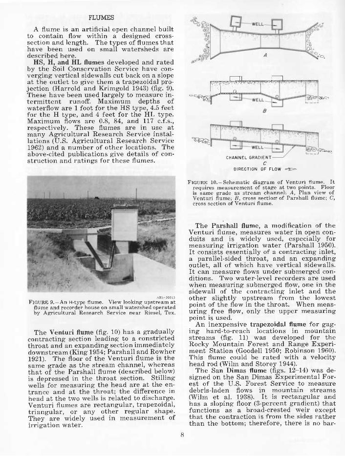
The Venturi flume (fig. 10) has a gradually contracting section leading to a constricted throat and an expanding section immediately downstream (King 1954; Parshall and Rowher 1921). The floor of the Venturi flume is the same grade as the stream channel, whereas that of the Parshall flume (described below) is depressed in the throat section. Stilling wells for measuring the head are at the en- trance and at the throat; the difference in head at the two wells is related to discharge. Venturi flumes are rectangular, trapezoidal, triangular, or any other regular shape. They are widely used in measurement of irrigation water.
FIGURE lO.-Schematic diagram of Venturi flume. It requires measurement of stage at two points. Floor is same grade as stream channel: A, Plan view of Venturi flume; B, cross sectiorr of Parshall flume; C, cross section of Venturi flume.
The Parshall flume, a modification of the Venturi flume, measures water in open con- duits and is widely used, especially for measuring irrigation water (Parshall 1950). It consists essentially of a contracting inlet, a parallel-sided throat, and an expanding outlet, all of which have vertical sidewalls. It can measure flows under submerged con- ditions. Two water-level recorders are used when measuring submerged flow, one in the sidewall of the contracting inlet and the other slightly upstream from the lowest point of the flow in the throat. When meas- uring free flow, only the upper measuring point is used.
An inexpensive trapezoidal flume for gag- ing hard-to-reach locations in mountain streams (fig. 11) was developed for the Rocky Mountain Forest and Range Experi- ment Station (Goodell 1950; Robinson 1960). This flume could be rated with a velocity head rod (Wilm and Storey 1944).
The San Dimas flume (figs. 12-14) was de- signed on the San Dimas Experimental For- est of the U.S. Forest Service to measure debris-laden flows in mountain streams (Wilm et al. 1938). It is rectangular and has a sloping floor (3-percent gradient) that functions as a broad-crested weir except that the contraction is from the sides rather than the bottom; therefore, there is no bar-

rier to cause sediment deposition. Depth measurements are made in the parallel- walled section at about the midpoint. Rapid flow keeps the flume scoured clean. ,
FIGURE 11.-Trapezoidal flume used to gage streamflow of Upper Fool Creek, Fraser Experimental Forest, Fraser, Colo. The man in the picture is holding a velocity head rod that has been used to rate this flume.
FIGURE 13.-A l-foot San Dimas flume (on left) and broad-crested weir used to gage streamflow of Fool Creek, Fraser Experimental Forest, Fraser, Colo.
TRANSITION, PARALLEL WALL -SECTION —t~ SECTION
UPSTREAM END SLOT
I -lé^W-
-w—J—w— -Lp=2W —
DOWNSTREAM END
SILT TRAP-
SECTION A-A -L=3^W-
PLAN
W= WIDTH OF FLUME
Lp= LENGTH OF PARALLEL FLUME SECTION
L= TOTAL LENGTH OF FLUME
R= RADIUS OF TRANSITION
SILT TRAP
^ PIPE TO
STILLWELL
SECTION B-B
FIGURE 12. —Generalized drawing of San Dimas flume. This design has been used for flumes with widths of 0.5, 1.0, 2.0, 3.0, 4.0, 6.0, and 10.0 feet.
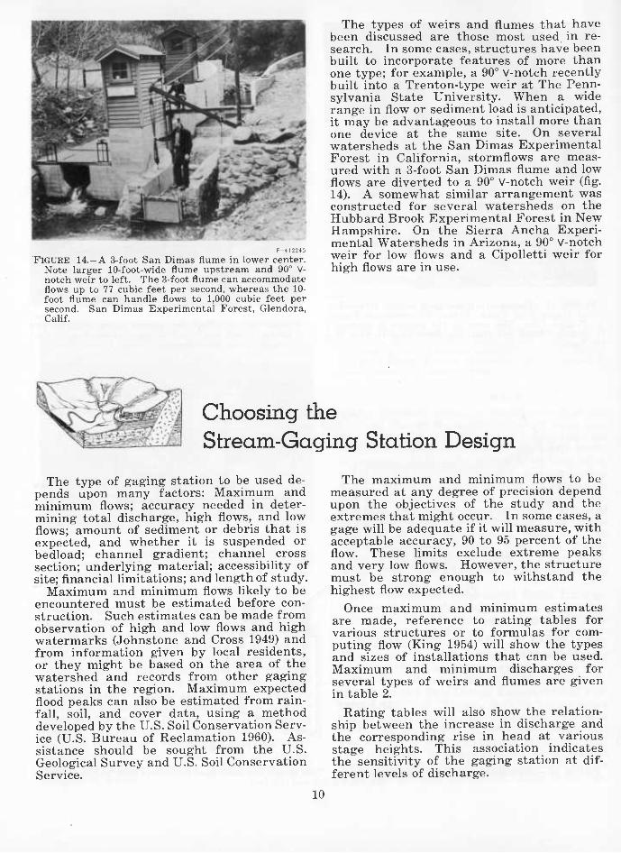
FIGURE 14.-A 3-foot San Dimas flume in lower center. Note larger 10-foot-wide flume upstream and 90° V- notch weir to left. The 3-foot flume can accommodate flows up to 77 cubic feet per second, whereas the 10- foot flume can handle flows to 1,000 cubic feet per second. San Dimas Experimental Forest, Glendora, Cahf.
The types of weirs and flumes that have been discussed are those most used in re- search. In some cases, structures have been built to incorporate features of more than one type; for example, a 90° V-notch recently built into a Trenton-type weir at The Penn- sylvania State University. When a wide range in flow or sediment load is anticipated, it may be advantageous to install more than one device at the same site. On several watersheds at the San Dimas Experimental Forest in California, stormflows are meas- ured with a 3-foot San Dimas flume and low flows are diverted to a 90° V-notch weir (fig. 14). A somewhat similar arrangement was constructed for several watersheds on the Hubbard Brook Experimental Forest in New Hampshire. On the Sierra Ancha Experi- mental Watersheds in Arizona, a 90° V-notch weir for low flows and a Cipolletti weir for high flows are in use.
Choosing the Stream-Gaging Station Design
The type of gaging station to be used de- pends upon many factors: Maximum and minimum flows; accuracy needed in deter- mining total discharge, high flows, and low flows; amount of sediment or debris that is expected, and whether it is suspended or bedload; channel gradient; channel cross section; underlying material; accessibility of site; financial hmitations; and length of study.
Maximum and minimum flows likely to be encountered must be estimated before con- struction. Such estimates can be made from observation of high and low flows and high watermarks (Johnstone and Cross 1949) and from information given by local residents, or they might be based on the area of the watershed and records from other gaging stations in the region. Maximum expected flood peaks can also be estimated from rain- fall, soil, and cover data, using a method developed by the U.S. Soil Conservation Serv- ice (U.S. Bureau of Reclamation 1960). As- sistance should be sought from the U.S. Geological Survey and U.S. Soil Conservation Service.
The maximum and minimum flows to be measured at any degree of precision depend upon the objectives of the study and the extremes that might occur. In some cases, a gage will be adequate if it will measure, with acceptable accuracy, 90 to 95 percent of the flow. These limits exclude extreme peaks and very low flows. However, the structure must be strong enough to withstand the highest flow expected.
Once maximum and minimum estimates are made, reference to rating tables for various structures or to formulas for com- puting flow (King 1954) will show the types and sizes of installations that can be used. Maximum and minimum discharges for several types of weirs and flumes are given in table 2.
Rating tables will also show the relation- ship between the increase in discharge and the corresponding rise in head at various stage heights. This association indicates the sensitivity of the gaging station at dif- ferent levels of discharge.
10

TABLE 2,—Maximum and m^inimum. dis- charges for several types of weirs and flumes in cubic feet per second (approximate)
WEIRS
Type Mini- mum
Maxi- mum
Sharp-crested weirs: 2 feet high, 90° V-notch <0.001
<.001 1 .24 1.30 1.46
2.017 2.025 2.037
.026
14 2 feet high, 120° V-notch 24 2 feet high, 6 feet wide rectangular... 2.75 feet high, 8 feet wide Cipolletti... 4 feet high, 12 feet wide Cipolletti
Broad-crested weirs: Triangular 2 :1 side slopes
56 123 323
3 510 Triangular 3 :1 side slopes 3 803 Triangular 5 :1 side slopes 3 1 440 2 feet high Columbus deep notch 62
FLUMES
HS type: 0.4 foot hie-h. 1 0.001 0 1 LO foot hio-h ' .002 8
H type: 1.0 foot hiP-h ' 004 2 2.0 feet high 1 .007 11 4.5 feet hie-h 1 .015 84
HL type: 4.0 feet high. ' .03 117
San Dimas: 1 foot WIHP .1
2 10 36
6 3 feet wide 77 6 feet wide 318 10 feet WIHP 1,000
Trapezoidal: 1-foot-wide throat, 4 feet high, 30° 1.15 350
side slopes. Parshall:
1 foot wide, 2 5 feet high .4 16 2 feet wide, 2 5 feet high .7 33 4 feet wide, 2.5 feet high 1.3 68 8 feet wide, 2.5 feet high. 4.6 140
' Flow at 0.05-foot head. •^ Flow at 0.1-foot head. 3 Flow at 6-foot head with cross-sectional area of 300
square feet in the channel of approach 10 feet upstream from center of crest.
Rating" can be simplified by choosing a design for which a stage-discharge relation- ship has been determined in the laboratory. Before construction, the conditions under which the design was tested should be care- fully studied. After construction, the labora- tory rating should be checked at various stage heights by direct measurement with a current meter, velocity head rod, or another instrument for determining velocity, or by volumetric measurements. Rating-table dis- charges of sharp-crested V-notch weirs for heads of less than 0.2 foot can be expected to be inaccurate (Thomas 1957). For heads be-
low 0.2 foot, the weir can be rated in the field, as will be described later.
If a design is used for which a rating has not been determined, the installation is rated by making measurements at various stages, using a current meter (Pierce 1941a; Corbett and others 1943) or other means. Peak ñows may be difficult to measure.
Where excessive amounts of suspended sediment, bedload, and floating debris are en- countered, flumes are preferable. Weirs would be unsatisfactory because the basin would trap this material, which would alter the weir rating, and debris would clog the crest of the weir, giving grossly inaccurate measurements. Broad-crested weirs are often used on agricultural watersheds where grass and other debris would lodge on a sharp-crested weir and invalidate the rating curve (U.S. Agricultural Research Service 1962).
The gradient of the stream channel may aff'ect choice of design. If the gradient is too low, it may be impossible to install a weir that will meet the requirements of a stand- ard rating (depth of water below crest equal to at least 2.5 times the maximum head to be measured). A control with less elevation may have to be built, and the station will then have to be rated by current meter or other means. It was largely because of the low channel gradient that the combination 90° V-notch and Trenton weir was installed at the Pennsylvania State University. Low flows through the 90° V-notch correspond to the standard rating, but higher flows are rated with a pygmy meter.
The channel cross section and streambanks may dictate design. Under some conditions, a cutoff wall high enough to satisfy rating re- quirements would have to be of considerable length to tie into solid material at the sides. The cost of such a wall might rule out this type of installation.
Underlying material must be considered. If permeability is a problem, either a water- tight-box weir design, which can support an artificial head of water, or a flume will be necessary.
The type of weir or flume and the material used in its construction may be influenced by the accessibility of the site. For example, though ready-mix concrete is often the best material, it cannot be used on forested water- sheds where the terrain is so rugged that it would not be practicable to build access roads capable of accommodating ready-mix trucks. The trapezoidal flume of the Rocky Mountain Forest and Range Experiment Station was designed for sites of poor accessibility, some reached only by packhorse.
717-764 0-64-3 11

Length of study and financial limitations inñuence the choice of construction ma- terials. For a long-term study, concrete is best. It should be of the best grade in order to prevent leakage, reduce erosion, and in- sure maximum strength. Weir crests of concrete may be eroded, with resultant change in rating. Crest erosion may be ex- cessive where water is especially acid —a notch of brass or some other noncorrosive material should be installed. Concrete blocks were used in recent weir construction by personnel of the Rocky Mountain Forest and Range Experiment Station and on the Baltimore City Watershed in Maryland.
Wood, preferably treated for decay resist- ance, is often used for economy in structures that will be in service for a limited time (Whipkey 1961). The H-type flumes, which have been described, are constructed of sheet brass or galvanized iron.
A satisfactory but inexpensive weir-basin liner of 8-mil black vinyl plastic has been used at experimental watersheds in Baltimore, Md. The liner was placed inside a weir box 10 feet wide and 20 feet long built of 2-inch oak planks. A V-notch blade was bolted, over the plastic, to the box. The vinyl was ce- mented to the box and plate with asphalt- asbestos roofing cement. Cost figures for this weir are given in the appendix.
With weirs, sharp crests give greater ac- curacy than broad crests. Blades of sharp- crested weirs are constructed of angle iron or steelplate, ground to a sharp edge or to a flat edge one-sixteenth inch wide, and set into concrete cutoff walls or dams. Blades may be dented, bent, rusted, and clogged with debris. In many locations they must be
screened to prevent clogging, and care should be exercised when working near them; some maintenance, such as annual painting, is required.
At the Coweeta Hydrologie Laboratory in North Carolina the following criteria were used in selecting weir designs: ^
1. Sharp-crested weirs were used where sediment production would not exceed that from protected watersheds.
2. 90° V-notch weirs were used where dis- charge 95 percent of the time was expected to be 0,01 to 8 c.f.s.
3. 120° V-notch weirs were used where flow 95 percent of the time was expected to be between 0.10 and 20 c.f.s.
4. Rectangular and Cipolletti weirs were used where flows less than 2 c.f.s. would sel- dom occur and where there was frequent need to measure discharges greater than 30 c.f.s. Rectangular weirs less than 5 feet long are so restricted in the range of flows meas- ured as compared with the 120° V-notch that they were never used.
Flumes are often satisfactory where weirs are impracticable. They can handle debris- laden flows better; even so, such flows may be difficult to measure. With flumes, velocity of approach is less of a problem than with weirs. There is less loss in head with flumes than with weirs; thus, they can be used in channels with low gradients; this is one of the main reasons why flumes are used in measurement of water for irrigation. And flumes, requiring no excavation for ponding, may be easier and cheaper to install.
^ Personal correspondence with Marvin D. Hoover, June 6, 1961.
A Sharp-Crested 120° V-Notch Weir
A sharp-crested V-notch weir is excellent for measuring streamflow in small moun- tain streams. Under certain conditions, highly accurate measurements can be taken of both high and low flows. For example, a 2-foot-high 120'' V-notch weir can be used to accurately measure flows approaching 25 c.f.s. and those 0.086 c.f.s. or less. This type of weir has been used since the 1930's at the Coweeta Hydrologie Laboratory of the U.S. Forest Service, where a stage-discharge for- mula was developed (Hertzler 1938). The
formula is: Q = 4.43 W^^^, in which Q is the discharge in cubic feet per second and H is the head in feet (measured 6 feet up- stream from the blade). The stilling basin of the weir on which this formula was deter- mined was large enough to obtain a minimum side contraction 2.5 times the head, with a bottom contraction of 2.5 feet.
The following section presents the design and method for constructing a sharp-crested 120° V-notch weir 2 feet high. Detailed de- scriptions of other types of stream-gaging
12

stations are not given. Except for their blade design, rectangular, trapezoidal, and Cipolletti weirs are similar in design and function to sharp-crested V-notch weirs. Sharp-crested 120° V-notch weirs are illus- trated in figures 5 and 15.
F-503138
FIGURE 15.-A 2-foot, 120° v-notch weir with blade of 3/8-inch galvanized metal plate. Hubbard Brook Ex- perimental Forest, West Thornton, N.H.
DESIGN
The simplest weir in design and construc- tion consists of a watertight cutoff wall that spans the stream channel, creating a pond or stiUing basin upstream. The ends and base of the cutoff wall are tied into bedrock or other impermeable material.
A tighter container is required where the channel bottom is permeable, where bedrock is cracked or irregular, or where the stream channel does not follow naturally worn V- shaped bedrock; such conditions are common in glaciated areas. Here a watertight box is required-a box that is open at the top and upstream end. The box may be equipped on the upstream end with wingwalls that ex- tend into the sides of the streambank. These walls will funnel the streamflow into the box and thus serve in part as a cutoff wall. This design makes it possible to inter- cept all of the surface flow at the upstream edge of the box; the artificial head created to satisfy weir requirements does not re- sult in increased leakage through a perme-
able channel bottom as it would with the simpler cutoff wall design.
Where the stream gradient is low and the geology permits, a four-sided box may be sunk in the stream channel. Streamflow enters the box by dropping down a vertical wall on the upstream side.
The three types of weir basins described here are shown in figure 16. All of them have a blade mounted in a notch on the down- stream wall, drain and intake pipes, instru- ment shelter or gagehouse, and stilling well. The watertight box is more compUcated, and construction is more costly than for the cut- off wall type.
-STREAM CHANNEL CONCRETE CUTOFF WALL-
EXCAVATED BASIN IN IMPERMEABLE MATERIAL
DIRECTION OF FLOW-t=^
FIGURE 16.-Three types of weir basins: A, Weir basin formed by simple cutoff wall spanning stream channel; B, weir basin formed by watertight box with front wall, two sidewalls, and floor with open upstream end; C, weir basin formed by sunken watertight box with four sides and floor.
Cutoff Wall
A cutoff wall was constructed on the Fer- now Experimental Forest, near Parsons, W. Va. The concrete wall was built across the stream channel, with its base firmly im- bedded in the impermeable bedrock. Struc- tural views of this cutoff wall are given in figure 17.
13

SECTION A-A SECTION B-B
FIGURE 17.-Plans for concrete cutoff wall constructed at Fernow Experimental Forest, Parsons, W. Va.
WATER-STAGE RECORDER
|j^ir;v^^:f ■•■ .-■: .f.^t:.^^-:v^
/::■;/:•-• L AJÍ _ _'_ \ J ■.-^■:;j "^^^^"^-^^"^W^^^i^:^^^^
FIGURE 18. —Schematic diagram of 120° V-notch weir, watertight-box design.
14
The top of the cutoff wall is level with the top of the V-notch. At the streambanks, the cutoff wall projects 2 feet higher to provide a rectangular section above the V to accommo- date flows that exceed the V-notch capacity. The width of this rectangular section is 12 feet.
Watertight Box
The watertight-box type is an elaboration of the cutoff-wall design. Instead of span- ning the width between natural stream- banks, the cutoff wall is joined on both ends by sidewalls (ñg. 18). A concrete floor forms the bottom of the basin if the natural floor is permeable.
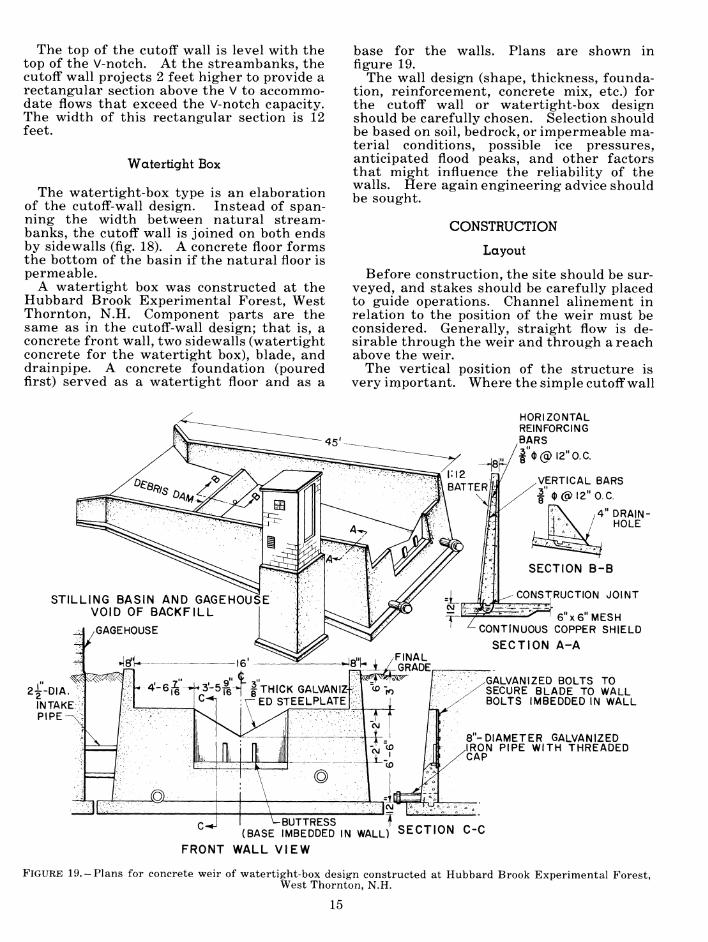
A watertight box was constructed at the Hubbard Brook Experimental Forest, West Thornton, N.H. Component parts are the same as in the cutoff-wall design; that is, a concrete front wall, two sidewalls (watertight concrete for the watertight box), blade, and drainpipe. A concrete foundation (poured first) served as a watertight floor and as a
base for the walls. Plans are shown in figure 19.
The wall design (shape, thickness, founda- tion, reinforcement, concrete mix, etc.) for the cutoff wall or watertight-box design should be carefully chosen. Selection should be based on soil, bedrock, or impermeable ma- terial conditions, possible ice pressures, anticipated flood peaks, and other factors that might influence the reliability of the walls. Here again engineering advice should be sought.
CONSTRUCTION
Layout
Before construction, the site should be sur- veyed, and stakes should be carefully placed to guide operations. Channel alinement in relation to the position of the weir must be considered. Generally, straight flow is de- sirable through the weir and through a reach above the weir.
The vertical position of the structure is very inriportant. Where the simple cutoff wall
HORIZONTAL REINFORCING BARS |"(D(q)l2"0.C.
VERTICAL BARS I" 0(0)12" o.e.
4" DRAIN- HOLE
SECTION B-B
CONSTRUCTION JOINT
2Í-DIA
6x6 MESH CONTINUOUS COPPER SHIELD
SECTION A-A
GALVANIZED BOLTS TO SECURE BLADE TO WALL BOLTS IMBEDDED IN WALL
8-DIAMETER GALVANIZED IRON PIPE WITH THREADED CAP
CVJ
-BUTTRESS T<Mr/--rir%M /- I- (BASE IMBEDDED IN WALL) SECTION C-C
FRONT WALL VIEW
FIGURE 19.-Plans for concrete weir of watertight-box design constructed at Hubbard Brook Experimental Forest, West Thornton, N.H.
15

is used, one guideline is to maintain the origi- nal stream gradient above the weir basin. The vertex of the notch should ordinarily be at the elevation of the original streambed or somewhat lower. Thus, the impounded water will be contained in the basin and will not back up into the natural stream channel.
The dimensions of the basin must be deter- mined and staked out. The width should be at least the width of the notch plus a distance on each side of the notch equal to 2.5 times the maximum head. Thus, for the 120° V- notch for an expected head of 2 feet, the width should be at least 17 feet.
Determining the length of the basin is often more difficult. One objective in oper- ating a weir is to spread the flow evenly over the whole cross section at the upstream edge of the basin. Where this can be done, a short weir basin suffices. Generally, the flow does not enter uniformly even if efforts are made to spread it; therefore, the weir basin should be long enough to even out the flow before it reaches the stilling well intake pipes and the notch. Basins are often constructed 20 to 30 feet long for weirs with notches 2 feet high.
Where it is not feasible to dig a basin below the normal stream channel —for example, where hard bedrock forms the channel —the length of the basin will be governed by the slope of the stream channel. A channel with a gradient of one vertical unit to three hori- zontal units is almost ideal; it would require a basin about 25 feet long. If the stream gradient is very low, it may be impractical to use the watertight-box stream-gaging de- sign because the length of the basin walls necessary to fulfill the hydraulic requirement would be prohibitive.
The recommended depth of the weir pond at the notch (at least 2.5 times the head below the vertex of the V), the stream gradient, and the material underlying the stream channel should also be considered in determining the length of the basin. In some cases, setting the elevation of the notch as previously de- scribed would require considerable excava- tion below the level of the streambed if the basin were short. One answer might be to lengthen the basin.
Besides consideration of the layout of the stream-gaging site, provision should be made for sufficient workspace around the site for workers, tools, equipment, and forms, and for unloading and storing materials. If con- crete is to be used, the operation should be planned so that the materials and mixer or ready-mix trucks are above the highest point in the structure. This will ease the job of transporting the concrete to the forms.
Excavation
The first phase in the construction of a stream-gaging station is excavation. It is undertaken for one, two, or all three of the following reasons: (1) To reach impervious material to restrict water loss around the control; (2) to secure a firm foundation for the structure; and (3) to provide a pond in the channel above the control.
The type and size of the stream-gaging sta- tion and the characteristics of the soil and underlying strata will determine the dimen- sions of the excavation.
Unnecessary excavation should be avoided. Excavation increases the possibility of the streambanks becoming unstable and eroding. Also, unconsolidated fill material may permit seepage loss. The material removed in exca- vating should be piled away from the channel to prevent it from washing into the stream.
Excavation may be done by mechanical equipment such as a bulldozer, backhoe, or shovel. Handwork will be necessary to com- plete the operation where the bedrock is fissured or uneven, or where mechanized equipment cannot operate. In some cases dynamite may be used to blast trenches, re- move uneven rock ledge, or make depressions for stilling basins. However, it should be used sparingly and carefully, for the explo- sions may shatter the bedrock or create cleav- ages that could result in serious leakage.
If a simple cutoff wall will be a satisfactory control, excavation will only involve the dig- ging of a trench across the streambed and into the banks on both sides, and hollowing a cavity for a stilling basin.
Cutoff Wall
Because one of the prime functions of the cutoff wall is to force all water within the basin to flow over the control notch, the cutoff wall must make a watertight junction with underlying natural material.
If the wall is to rest on bedrock, the sta- bility of the wall and watertightness of the wall-bedrock junction may be achieved in one of several ways. Keys, IJ^ to 2 inches wide and deep, may be drilled in the bedrock (fig. 20). This key will add to the watertightness by creating a larger surface area at the joint; it will also secure the concrete wall to the bedrock, preventing sliding of the structure. Steel anchor pins, imbedded in both the rock ledge and the concrete wall, also secure the walls. Footings of poured concrete perhaps 3 feet wide may provide both stability and watertightness.
If the wall is to be built on tight subsoil, it may be well to cut trenches or keys. Care should be taken so cracks do not form and so
16

REINFORCING STEEL
CONCRETE
KEY FORMED IN CONCRETE
CONCRETE
HOLES EVERY 12"
CONTINUOUS KEY 1^' X 1^' IN LEDGE
A. WALL KEYED TO BEDROCK B. WALL WITH CONCRETE FOUNDATION
C. WALL WITH WIDE BASE
FIGURE 20. —Methods used to secure concrete walls to rock ledge.
the material is not shattered during excava- tion. With some subsoils, it may be advisable to pour a concrete footing considerably wider than the wall proper. The width of the foot- ing- depends on the bearing strength of the soil. Engineering advice should be sought if there is any question on this point.
A simple cutoff wall is not suitable where the substratum is permeable or where im- permeable material does not form a confining channel; for example, an impermeable sub- stratum may be present on one bank but may dip away from the other bank. Then a new site must be found, or a watertight weir box must be built on the one excavated.
Even though the weirs described in this re- port do not impound so much water that their failure would endanger life and property, the simple cutoff wall and the front or down- stream wall in the watertight-box design must be built according to sound engineering principles. It is more practicable to provide a large safety factor than to determine pre- cise strength requirements. Sliding, over- turning, and uplift forces should be calcu- lated. Engineering assistance may be needed. Forces affecting concrete gravity dams and requirements for stability are given in **Design of Small Dams" (U.S. Bureau of Reclamation 1960).
As noted in figures 17 and 19, the concrete cutoff wall and front wall have a vertical upstream face and a battered or gently sloping downstream face, which makes the
wall thicker at the bottom than at the top. The battered wall is more stable than a verti- cal wall; it can withstand greater pressures resulting from high flows, ice pressure within the basin, or frost action from soil around the basin. The larger basal surface area in the battered wall also helps maintain a water- tight joint. Slopes for the battered face may vary from 4 to 12 vertical units to 1 horizontal unit. The steeper slopes (such as 12:1) are recommended only when reinforced concrete is used.
Where freezing temperatures are persist- ent, reinforced concrete should be used. Re- inforcing steel in concrete permits the use of considerably less concrete for equal strength and also lessens the possibility of wall cracks resulting from the expansion and contraction of the concrete with temperature changes. An example of the amount of rein- forcing steel required for a 12:1 battered wall is given in figure 19.
Upstream and downstream forms are needed for constructing the walls. Form material usually consists of horizontal sheathing (1-inch tongue-and-groove boards or ^-inch plywood) with vertical 2- by 4- inch studs for support. The vertical studs should be spaced 12 inches on centers. If tongue-and-groove boards are used, they should be fastened to the 2- by 4-inch studs with a single six-penny nail at each stud. Figures 21, 22, and 23 illustrate one method of form construction.
17

WOOD BRACE
SPIRIT LEVEL ADJUSTED TO DESIRED SLOPE
•2x4 STUDS EXTERIOR FORM
INTERIOR FORM
B
INTERIOR FORM -ANGLE
EXTERIOR FORM EXTERIOR FORM INTERIOR FORM
WOOD WEDGE ROD CLAMP,
BRACES
2x4 WALE
^;2x4 HEATHIN6'
TIE ROD,
I" WATER PROOF SEALER I" WOOD
CONE WASHER
FIGURE 21. —Plans for constucting forms for concrete walls for weir at Hubbard Brook Experimental Forest, West Thornton, N.H.: A, cross section of wall forms; B, top view of corner arrangement of wall forms; C, cross section of wall at the sloping section where blade is attached; D, details of tie-rod arrangement for bracing wall forms.
F-ÍJ03139
FIGURE 22. —Downstream view of forms for concrete basin walls. Most of the interior form is complete. Note vertical iron reinforcing rods in place, exposed bedrock foundation, and flaring upstream wingwalls. Weir constructed at Hubbard Brook Experimental Forest, West Thornton, N.H.
F-503140
FIGURE 23.— Front corner view of weir shown in figure 22. Interior form is complete, and exterior form is almost complete. Note position of blade, reinforcing iron, tie rods passing between both forms, and hori- zontal wales for bracing.
t#

Although plywood is commonly used for sheathing in the building trades (because it can be used repeatedly), matched boards are generally preferred for weir construction be- cause they can be more easily fitted to the rough surface upon which the structure will rest. A poured concrete footing will elimi- nate much of the rough surface and speed up form construction; bolts placed in the con- crete can be used to anchor the forms.
Because a tremendous amount of pressure develops against the forms when the concrete is poured, the forms should be rigidly braced to prevent their shifting out of position.
Several methods may be used to keep the forms separated and braced. Wire (No. 9, A.W.G.) may be strung and tied between the two forms at 2-foot intervals, both hori- zontally and vertically. Tie rods (M-inch steel rods and fittings) can keep the forms properly separated and can reduce consider- ably the additional bracing needed. Where small sections of wall are involved, the separate walls may be braced independently of each other by external wood braces. If wires or tie rods are used, they should pass through the entire form and be tightly se- cured at each end to horizontally placed braces or wales set perpendicular to the ver- tical studs. To be effective the wales should span four or more studs, and wale junctions should overlap two studs. Figures 21, 22, and 23 illustrate a method of bracing forms with tie rods.
In constructing the forms, provision should be made for placement of the weir blade and drainpipes.
The weir blade or a template of it should be mounted temporarily in its proper location on the wall forms. Bolts that will ultimately hold the blade in place should be positioned and secured to the forms so that they will not move during the concrete pouring. This may be done by inserting them through accom- modating holes in the template or blade and by wiring them to the forms.
Where angle iron is used for the weir blade, the portion of the concrete directly below the V should be sloped sufficiently to prevent ob- struction of the free-falling water. Con- struction of forms for these sloping walls requires considerable time and eifort.
Building the forms requires some skill and careful planning. No attempt will be made to discuss all construction details; however, figures 21, 22, and 23 illustrate some of the techniques. To maintain the same slope for all battered surfaces, a carpenter's level should be used —one whose spirit level can be adjusted to any 360° position. The desired slope, for example 6:1, can be made by fas- tening a board to form the hypotenuse to a 1-foot horizontally placed board and a 6-foot
vertically placed board. When the carpen- ter's level is placed on the board forming the hypotenuse, the spirit level should be ad- justed to the level position. The carpenter's level may then be used to set all studs to the proper battered slope.
Where concrete walls are designed to jut into the streambank, the earth sides of the trench dug into the bank may be satisfactory form walls. This obviates the need for back- fill and helps reduce the chance of seepage between streambanks and wall. Where back- filling is done, the choice of material is important. Backfill consisting of four parts loam soil and one part Bentonite clay mixed dry in a cement mixer has been used success- fully at the Fraser Experimental Forest in Colorado.
The best time for constructing the cutoff wall is during periods of low flow. The stream may be diverted around the construc- tion by a flume or ditch along the bank. Or it may be passed over the cutoff wall or through the notch by a flume or pipe. Another alternative is to route it through the drainpipe in the base of the cutoff wall. A moderate amount of ponded or still water in the excavation is permissible; the concrete when poured will displace it. But even a small amount of flow or seepage of moving water through the concrete before it has set will be disastrous; it will carry the cement away from the mix, and leaks will result.
Sidewalls
Watertight sidewalls used in the water- tight-box design are constructed similarly to the front or cutoff walls. Intake pipes to the well under the gagehouse have to pass through one sidewall, and they should be pro- vided for in the forms.
Where the cutoff wall alone is relied upon to control streamflow, construction require- ments for sidewalls are not exacting, for their purpose is merely to prevent slumping of the banks and erosion by water. These sidewalls should not be watertight because water held back would exert pressures that might cause damage. A porous dry-built stone wall is satisfactory (fig. 24). Concrete blocks, without mortar, can be used. Wood planks or logs, preferably treated for decay resistance, will also be suitable. They should be supported by posts securely tied into the banks; for example, by use of buried anchor logs. A pole across the basin above the high water level may also be used to keep the sides vertical. Under some conditions, the sides of the basin can be sloped so that building of a wall is not necessary. Planting grass on the banks will help control erosion.
19
. - ' ■ '• ■ .^M^:^
9^^'T^'-^' ^^^^^D^K~"~
^^^^^^^ 4-
■^m^ ^^^^Ê
"HH ̂ ^^^|HpP r^w
F-503132
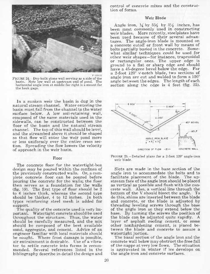
FIGURE 24.— Dry-built stone wall serving as a side of the basin. Note low wall at upstream end of pond. The horizontal angle iron at middle far right is a mount for the hook gage.
control of concrete mixes and the construc- tion of forms.
Weir Blade
Angle iron, 3^ by 3J4 by 33^ inches, has been most commonly used in constructing weir blades. More recently, steelplates have been used because of their several advan- tages. The angle-iron blade is mounted on a concrete cutoff or front wall by means of bolts partially buried in the concrete. Some- what similar techniques could be used for other weir shapes —for instance, trapezoidal or rectangular ones. The upper edge is ground to a flat or sharp edge and should have a 45-degree bevel below the edge. For a 2-foot 120° V-notch blade, two sections of angle iron are cut and welded to form a 120° angle between the edges. The length of each section along the edge is 4 feet (fig. 25).
In a sunken weir the basin is dug in the natural stream channel. Water entering the basin must fall from the channel to the water surface below. A low soil-retaining wall, composed of the same materials used in the sidewalls, can be constructed between the floor of the basin and the natural stream channel. The top of this wall should be level, and the streambed above it should be shaped so that flow will enter the weir pond more or less uniformly over the entire cross sec- tion. Spreading the flow lowers the velocity of approach in the weir basin.
Floor
The concrete floor for the watertight-box design may be poured within the confines of the previously constructed walls. Or, a com- plete concrete floor can be poured before pouring the concrete for the walls; the floor then serves as a foundation for the walls (fig. 19). The first type of floor should be 2 to 6 inches thick, whereas the second type should be thicker, 4 to 12 inches. In both types reinforcing steel mesh is added for support.
The quality of the concrete used is very im- portant. Watertight concrete should be used throughout the structure. Thus, the water should be carefully measured, and the mix should be composed of the best available sand, aggregate, and cement. Advice of an engineer familiar with local materials should be sought. Where frost damage is possible, air entrainment is desirable. Use of a vibra- tor to settle concrete into forms is recom- mended. Several references listed in the bibliography describe in detail the design and
6.928' 1
1 , 3.464- ™
spv^^i**'
\^^ ! 2.000 ^"^^ H_^60q^ U ^45° BEVEL
^^^^ ~ /-BOLT
ADE ^ ^ •• •• \ •. .\ \ \ •!
ANGLE IRON BL *. .'^ ; Í V.
] " X 3 j" X 3 i" Ï: ^^ ■%
DIRECTION OF FLOW _«=> CONCRETE WALL
FIGURE 25.-Detailed plans for a 2-foot 120° angle-iron weir blade.
Slots are made in the base section of the angle iron to accommodate the bolts and to facilitate placement of the blade. The up- stream face of the angle iron should be placed as vertical as possible and flush with the con- crete wall. Also, a vertical line through the bottom of the V should bisect the angle. To do this, shims are inserted between the blade and concrete, or the blade is adjusted by threading leveling screws through the base of the angle iron so they extend below the base. By turning the screws the position of the blade can be adjusted quite rapidly. A layer of asphalt roofing cement, or some other nonhardening cement, is placed be- tween the blade and concrete to assure a watertight juction.
The basal section of the angle iron and the concrete wall below may obstruct the free fall of the nappe at very low flows. The situation is aggravated in winter if ice develops on the angle iron and concrete surfaces.
20

The steelplate blade is made by cutting a notch in a rectangular section. It is bolted to the concrete flush with the upstream face of the wall over a rectangular or U-shaped opening in the wall. For a ^-inch metal plate, as shown in figures 15 and 19, but- tresses of yi- by 3- by 3-inch angle iron, 2.5 feet long, are set into the concrete and bear against the plate to provide rigidity. This type of blade allows unobstructed free fall of water from the notch. It is easier to fabri- cate than the angle-iron blade, and its use simplifies construction of the cutoff wall and placement of the blade in the wall. On the other hand, the plate is more expensive than the angle iron.
The blade, whether angle iron or sheet metal, should be treated with a primary coat of rust-preventive paint and then a coat of aluminum paint. Galvanizing the entire blade provides longer protection. Although galvanizing assures rust-free service, the up- stream surface and edge of the blade may not be smooth and uniform unless galvanizing is done with care.
To accommodate flows that exceed the ca- pacity of a 2-foot V-notch weir, rectangular sections of varying length and height are commonly added above the V-section (fig. 5). When flows exceed the V-notch capacity, the horizontal section above the notch assumes in part the characteristics of a broad-crested rectangular weir. Rating of these flows is very difficult, and discharge measurements are usually less accurate.
It is probably better to extend the V-notch higher than 2 feet than to rely on a rectangu- lar section above the V to accommodate high flows. As a large V would be difficult to in- stall properly, a 2-foot V-notch should prob- ably be fabricated and precisely positioned, and the additional height should be added later. If possible, for rating purposes, current-meter measurements should be made during high flows.
Drainpipes
A drainpipe should be set in the cutoff wall to drain the basin for cleaning. It should be large enough to accommodate the highest flow expected during maintenance. A 6- or 8-inch inside-diameter pipe is usually satis- factory. Its length depends on the thickness of the wall. It should be located so that the bottom of the pipe is at the low point on the floor of the channel along the cutoff wall. The drain should not be placed directly under the notch.
The pipe should be tilted slightly down- stream. The downstream end of the pipe should extend about 4 inches beyond the sur-
face of the wall and should be fitted with a screw-on cap. Iron lugs about 4 inches long and 1 inch in diameter should be welded to the side of the pipe to prevent the pipe from turning in the concrete when the cap is screwed on and off. A stout, short section of Wi- to 2-inch pipe welded across the cap will provide a mechanical hold for a steel lever for turning the cap.
Sometimes a second drainpipe is installed at a higher elevation. Such an arrangement permits draining most of the water and yet retention of accumulated debris in the basin for measurement. It will also facilitate draining the weir when a large accumulation of sediment blocks the lower pipe.
Debris Dam and Baffles
To minimize the debris that enters the weir basin and to help distribute flow evenly through the cross section, a dam can be built upstream across the channel. It can be made of rock, logs, timber, concrete, or other substantial construction; otherwise, it might wash out during high flow and do more harm than good. The top of the dam should be about 2 feet higher than the bottom of the notch. In the watertight basin the dam should be placed so that the water that is ponded upstream from the dam is within the conflnes of the walls and floor of the weir basin.
In cold climates where much ice develops, the debris dam should have a sloping surface on the downstream side to relieve ice pres- sure that may develop in the basin. Figure 26 gives an example of a debris dam.
Baffles of various designs are sometimes used in weir ponds to reduce velocity and distribute the flow uniformly across the pond.
F-503141
FIGURE 26.-Debris dam in basin of watertight box.
21

Captive floating baffles can relieve ice pres- sure. Baffles should be firmly secured to prevent them from becoming flotsam during floods.
In the stilling well under the gagehouse, the recorder float rises and falls as the water stage fluctuates. The stilling well, as its name implies, reduces wave action from the
Gagehouse and Well
Many shapes, sizes, and materials have been used for gagehouses. These vary from simple wooden box shelters just large enough to house the recording instrument to large concrete structures equipped with recorder, heater, telephone relay systems, and other apparatus (figs. 5, 8, 9, 11-13, and 27-29). The design depends on factors such as build- ing and maintenance costs, accessibility of materials, duration of installation, and sus- ceptibility to vandalism.
The most common type of gagehouse is like a telephone booth, 3 to 4 feet square, and con- structed of wood or concrete blocks. It shelters both the recording instrument and anyone servicing the instrument.
Screened openings or other ventilating de- vices should be provided in the walls. A barrier should be placed over the well to prevent water vapor from entering the water- level recorder or condensing on the tape. The instrument should rest on an immovable base. Plans for a gagehouse at the Hubbard Brook Experimental Forest are given in figure 30.
Concrete-block gagehouses (fig. 30) are more expensive than other types, but they are ex- ceedingly durable and weathertight, mainte- nance is negligible, accessibility to the well is good, movement of reference points or in- strument is practically nil, and they are virtually vandalproof. FIGURE 28. —Corrugated cylinder instrument shelter,
Onion Creek Experimental Watersheds, Calif.
WlS-RS-22
FIGURE 27.-Box-type instrument shelter with weir, stilling well, and observation platform on 330-acre watershed operated by the Agricultural Research Service near Fennimore, Wis.
FIGURE 29.—Wood-frame gagehouse at Fernow Experi- mental Forest, Parsons, W. Va.
22

INDUSTRIAL-TYPE" GALVANIZED STEEL DOOR
REINFORCED CONCRETE ^x FOUNDATION
\ REINFORCED CONCRETE ROOF
^INSTRUMENT BENCH
WATERTIGHT KEY JOINT
FIGURE 30. —Cutaway section for concrete-block gage- house for stream-gaging station at Hubbard Brook Experimental Forest, West Thornton, N.H.
weir basin, thereby lessening fluctuation of the hydrograph trace on the record chart.
Wells may be enclosed with corrugated steel cylinders, poured concrete, or concrete blocks. A firm foundation should be pro- vided for the walls, especially when they support the gagehouse.
The well should have adequate height to permit the recorder and floats to operate properly at the full capacity of the weir. Some wells, principally those of corrugated cylinders, can accommodate only the float and counterweight. In cold regions, addi- tional space may be required for placing an oil cylinder in the well to prevent freezing. In some cases it is desirable to construct wells large enough to permit a man to enter to adjust floats, clean, make hook-gage read- ings, and break up ice.
The location of the gagehouse and stilling well in relation to that of the weir basin is not critical if the relative positions of the intake pipes and weir blade are satisfactory. For cold regions, some people advocate that there be 1 to several feet of earth between the weir basin and stilling well because of the possi- bility of ice formation in the well. Some- times the stilling well is placed within the weir basin; however, unless the basin is much larger than usually necessary to meet hydraulic requirements, this may interfere
with even flow through the basin. When the well is placed outside a basin of watertight- box design, intake pipes and connections between weir basin and stilling well, and the stilling well itself, must be watertight.
Intake Pipes
The gage well is connected to the weir basin or stream channel by intake pipes. Two or more intake pipes are used, one placed higher than the other, to reduce the lag in well elevation during rapid changes of water stage in the basin, and to reduce the risk of an obstructed pipe and thus lost records. The pipes should be level.
Intake pipes also function as drainpipes when the pond is drained for cleaning.
In the watertight-box design, the intake- pipe opening to the basin may be set flush with the basin wall. In a simple cutoff wall, where the natural streambanks form the sides, the intake pipes should extend into the stream channel or basin, but not farther than the middle of the stream. A complete discussion of the design and construction of intake pipes is given by Pierce (1941b).
Metal pipes of wrought iron, steel, or gal- vanized iron are most commonly used. In- expensive asphalt-impregnated composition pipe may be satisfactory where freezing is not prevalent or for short-term installation. Where freezing is a problem, intake pipes should be insulated.
In the watertight-box design at the Hub- bard Brook Experimental Forest, two 2J^- inch inside-diameter galvanized iron pipes were placed 12 inches apart (one above the other), with their basin or stream ends flush with the inside of the basin wall, oriented at right angles to the stream channel, and with the openings located approximately 6 feet upstream from the blade.
The vertical placement of the pipes will de- pend on the location of the bottom of the V- notch and the position of the gagehouse. A feasible arrangement might be as follows: The upper pipe located 1 foot below the notch and the lower pipe about 1 foot above the basin floor or bed of the stream channel. Two additional pipes may be advantageous for handling stormflows: one located 1 inch below the V-notch and another 1 foot above the V-notch. If the weir will be subject to sediment deposition or thick ice layers, the number and location of pipes must be ade- quate to permit free flow of water between the basin and the well even though some of the pipes may become blocked.
Because it is essential to maintain the same water level in the well and basin dur-
23

ing all stages of flow, the ratio of the total cross-sectional area of the intake pipes to the stilling well should be at least 1:500, and preferably 1:100.
The basin ends of the intake pipes should be threaded, and a coupling should be at- tached. This will allow installation of re- ducers or baffles if necessary to assure equal levels in both the basin and the well during periods of high flow.
Placing the well directly in the weir basin eliminates the need for intake pipes. For example, a corrugated cylinder can be placed in or immediately adjacent to the basin, and a hydraulic connection between the basin and well can be obtained by cutting openings in the cylinder.
Cost of Construction
The cost of weir construction depends primarily on the type and size of the weir and expected duration of its use. Weirs made of a simple concrete cutoff" wall and wooden frame gagehouse with corrugated steel well will probably cost between $2,000 and $3,000. More elaborate weirs of the watertight-box design may cost between $4,000 and $10,000.
The appendix contains time, material, and cost figures for constructing weirs at the Fernow Experimental Forest near Parsons, W. Va.; the Hubbard Brook Experimental Forest in West Thornton, N.H.; the Leading Ridge Watersheds near State College, Pa.; and the Baltimore, Md., Watersheds.
Instrumentation
WATER-LEVEL RECORDER
The purpose of a stream-gaging station is to measure the water that passes through it. Most stream-gaging stations do this in- directly. What is actually measured is the level of the water surface, either the height of the water ponded upstream from the con- trol and influencing the amount of water passing over the control, or the actual height of water passing over the control. This height of water may be converted to quan- tity if the control section has been rated (stage-discharge relations derived).
When continuous records of streamflow are desired, a water-level recorder is em- ployed. The recorder makes a continuous or staccato trace of the water stage on a time chart. Where the installation is serviced infrequently (at intervals of more than 1 week but less than 6 months), a recorder employing a weight-driven continuous-roll chart is used (fig. 31). If the site can be visited frequently (once a week), a spring- driven drum-type weekly chart is satisfac- tory (fig. 32).
Water stage is conveyed to the recorder by a flexible tape or cable with an attached float. For the recorders shown in figures 31 and 32, a metal tape or cable rides over a pulley attached to the recorder. A counter- weight is affixed to the other end of the tape or cable to balance the float. The counter-
F-503134
FIGURE 31. —Stevens type A-35 water-level recorder for continuous roll chart. Note reference tape on right.
weight should be placed on the tape so that at zero flow (at the counterweight's highest point of travel) it is barely below the pulley. No obstructions should be met by the float or its counterweight throughout their travel from the highest to lowest position. Rela- tive sizes of floats and float wells are dis- cussed in the Hydraulic Data Book (Stevens n. d.).
For gaging stations where streamflow is intermittent, an automatic trigger device has been developed for FW-1 water-level re-
24
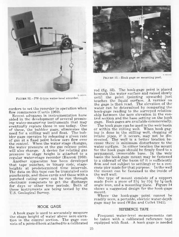
FIGURE 32.-FW-l-type water-level recorder.
corders to set the recorder in operation when flow commences (Curtis 1960).
Recent advances in instrumentation have aided in the development of several promis- ing water-measuring instruments that may eventually replace those in use today. One of these, the bubbler gage, ehminates the need for a stilling well and float. The bub- bler gage operates by releasing a given rate of gas at a fixed point below zero flow over the control. When the water stage changes, the water pressure at the gas release point will also change. A device for relating gas pressure to stage height is attached to a regular water-stage recorder (Barron 1960).
Another apparatus has been developed that tape punches, in binary code, stage- heights at predetermined time intervals. The data on this tape can be translated onto punchcards, and these cards and those with a punched rating curve can be run through electronic computers to get the discharge for days or other time periods. Both of these instruments are being tested by the U.S. Geological Survey.
HOOK GAGE
A hook gage is used to accurately measure the stage height of water above zero eleva- tion in the control section. The gage con- sists of a pointed hook attached to a calibrated
FIGURE 33. - Hook gage on mounting post.
rod (fig. 33). The hook-gage point is placed beneath the water surface and raised slowly until the point (pointing upwards) just touches the liquid surface. A vernier on the gage is then read. The elevation of the water can be determined by comparing the hook-gage reading to the surveyed relation- ship between the zero elevation in the con- trol section and the base setting on the hook gage. Hook gages are available commercially.
The hook gage can be used in the weir basin or within the stilling well. When hook gag- ing is done in the stilling well, clogging of intake pipes, if it occurs, may not be dis- covered. The well is a better location be- cause there is minimum disturbance to the water surface. In either location the mount for the hook gage should be firmly fixed to a permanent, immovable base. In the weir basin the hook-gage mount may be fastened to a sidewall of the basin (if it is sufficiently firm and not subject to settling) or to a con- crete pier made for that purpose. In the well the mount can be fastened to the inside of the well wall.
One type of mount consists of a support made from a piece of 3J^ by 33^ by J^-inch angle iron, and a mounting plate. Figure 34 shows a suggested design for the hook-gage mount.
Where the hook-gage point cannot be readily seen, a portable, electric water-depth gage may be used (Wilm and Collet 1941).
REFERENCE TAPE
Frequent water-level measurements can be taken with a calibrated reference tape equipped with float. A hook gage is needed
25
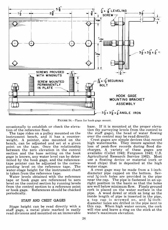
I -i;x -I LEVELING
I SCREW
^ ^--0
SCREWS PROVIDED i WITH WINGNUTS
SCREW MOUNTED PERMANENTLY IN PLATE
3^"x34x^ <
T ^"x l|'SECURING
BOLT
HOOK GAGE MOUNTING BRACKET
ASSEMBLY
P 3^'x3-^'x^*ANGLE IRON
FIGURE 34.-Plans for hook-gage mount.
occasionally to establish or check the eleva- tion of the reference float.
The tape rides on a pulley mounted on the instrument bench, and it has a counter- weight. A pointer, also mounted on the bench, can be adjusted and set at a given point on the tape. Once the relationship between the zero elevation in the control section and the base setting on the hook gage is known, any water level can be deter- mined by the hook gage, and the reference- tape pointer can be adjusted to the corres- ponding level on the reference tape. The water-stage height for the instrument chart is taken from the reference tape.
Water levels obtained with the reference tape or hook gage are referenced to zero level on the control section by running levels from the control section to a reference point or hook gage. References should be checked periodically.
STAFF AND CREST GAGES
Stage height can be read directly with a staff gage, a metal plate marked in easily read divisions and mounted on an immovable
base. If it is mounted at the proper eleva- tion (by surveying levels from the control to the staff gage), the head of water flowing over the control may be read directly.
Crest gages are simple devices that record high watermarks. They insure against the loss of peak-flow records during flood dis- charges. A variety of these gages are available (Collet 1942; Ferguson 1942; U.S. Agricultural Research Service 1962). Most use a floating device or material (cork or wood chips) that is deposited at the high water stage.
A crest gage may be made from a 1-inch- diameter pipe capped on the bottom. Sev- eral 3^-inch holes are provided in the pipe near the cap. The pipe is fastened in an up- right position in the basin so that the holes are well below minimum flow. Finely ground cork is placed on the water surface in the pipe. A wood dowel or stick as long as the inside length of pipe is inserted in the pipe, a top cap is screwed on, and 3^-inch- diameter holes are drilled in the pipe next to this cap. When high water occurs, the cork will rise and leave a ring on the stick at the water's maximum elevation.
26

Operating Procedures and Maintenance
Although the discussion in this section deals principally with weirs, it also is gener- ally applicable to flumes.
The major chores after installation of the water-level recorder and associated instru- ments are rating the weir, periodic chart changing, checking water levels with the hook gage or reference tape, cleaning and care of the instruments, and cleaning of the basin or channel.
RATING THE WEIR
Check measurements of the stage- discharge relationships (rating curve) should be made after the stream-gaging station has been built. The control section of the station should be built, if possible, according to the specifications of a model that has been rated under laboratory conditions. If this has been done, the rating curve of the laboratory model can be used unless there are differ- ences between the two —for example, up- stream approach conditions or weir blade surfaces or edges.
If the field model does not conform exactly to the specifications of the laboratory model, or if the field-control section has no labora- tory model, the control must be rated by measuring water flowing over it throughout the range of stage heights. In any case, some check measurements should be made after the station has been constructed.
Flows over a 120° V-notch weir up to 0.6- foot head may be measured by collecting in buckets or tanks the water passing over the weir in a selected time. At 0.6-foot head, use of a 400-gallon tank is advisable. A V-shaped trough of sheet metal can be used to direct the flow into the container. The position of the trough must not prevent aeration of the nappe.
The flow in cubic feet per second is com- puted from the time it takes to collect a con- tainer full of water; this is related to the stage height at the time. Eight to 10 stage heights well distributed between 0- and 0.6- foot head, with 2 to 4 replicates at each stage, are sufficient for this portion of the curve.
Stages are seldom at the proper height when it is convenient to test them. If flow is higher than the stage at which a test is desired, part of the flow may be diverted around the weir basin by a flume or a pipe (2- to 4-inch aluminum irrigation tubing is lightweight and convenient). Using this pro- cedure, two different low-flow stages can be rated during one visit to the installation.
Usually it is between 0- to 0.6-foot head that the measured flow varies appreciably from the laboratory rating. Slight variations in the structure of the blade will influence the discharge characteristics much more at low flows than at high flows.
Flows greater than 0.6 foot (approximately 1.27 cubic feet per second for a 120° V-notch weir) become unwieldy to measure by con- tainers and are measured with a current meter. Generally, velocities in the weir basin are too low to permit use of the current meter there.
Therefore, a natural nonturbulent section of the stream channel, directly above or below the artificial control, is used. A tem- porary flume made of boards, concrete, or other materials will provide a suitable meas- uring section. If the flume is constructed with sides of uniform width or regular geo- metric shape, the cross-sectional area may be readily computed.
The pygmy current meter with wading rod, a modification of the Price current meter, is used to rate field installations. A measur- ing tape is first stretched across a straight section of the stream. Measurements are made along the cross section so that each segment between the points of measurement accounts for about 5 percent of the total flow. At each point, total water depth is measured with a rule, and velocity of flow is determined with the meter and stop- watch. The meter has an earphone, and the number of clicks in the measuring period (usually 1 minute) indicates the velocity. When water depth is 0.5 foot or less, the meter is lowered halfway between the sur- face and the bottom; for depths between
27

0.5 and 2.0 feet, measurement is made at a point 0.6 of the depth from the surface; for depths over 2.0 feet, measurements are made at 0.2 and 0.8 of the depth and averaged.
The area and velocity of flow in each sec- tion are determined by averaging measure- ments of depth and velocity made at each side of the section; flow through the section is determined by multiplying area in square feet by velocity in feet per second. Total discharge is determined by adding the flow of the separate sections. Detailed instruc- tions for making current-meter measure- ments have been given (Pierce 1941a and 1941b; Corbett et al. 1943).
Flow through a rectangular section above a V-notch weir (fig. 5) creates a rating prob- lem. If the flow has not been rated by a current meter or by laboratory tests, a crude estimate of flow can be made by summing (1) the discharge of the V-notch weir at full capacity, and (2) the discharge of a broad- crested rectangular weir of the given width and a head measured from the base of the rectangular section.
PERIODIC CHART CHANGING
The time between chart changes depends on the instrument used, accessibility of the gaging station, and chart interval suitable for office handling. Although some re- corders will run for 6 months unattended, it is advisable, if possible, to visit the gages weekly or at other frequent intervals to check for malfunctions.
CHECKING WATER LEVELS
Each time the chart is changed or the in- stallation is serviced, the water level should be measured by hook gage or reference tape and recorded, along with the date and time of observation, both on the chart removed and on the new chart. This level indicates whether the instrument has been keeping an accurate account of the water stage and, if not, the corrections of the instrument or chart that should be made.
INSTRUMENT AND BASIN
A regularly scheduled instrument checkup and cleaning program is good practice. Where several gages are operated, it is ad- visable to have an extra instrument or spare parts, particularly clocks, ready as immedi- ate replacements.
Maintenance checks should also be made of the weir basin, walls, and weir blade. As necessary, the blade should be repainted and the nicks mended, and debris should be re- moved from the basin. Basin leaks can be reduced or stopped by coating the walls and
floor with asphalt cement, bentonite, or vinyl plastic, depending on the structural material.
The weir basin should be drained and cleaned before accumulation of sediment and other debris (such as leaves) reduces water depth beyond the point necessary to meet hydraulic requirements. It may also be necessary to clean out the stilling well. The frequency of draining and cleaning the weir basin will vary with the amount of sedi- mentation and basin size; it is often done annually.
TRASH SCREENS
Leaves, twigs, or other material lodged in the notch can cause considerable error in the stream-discharge record. To reduce this error, trees should be removed from the immediate vicinity of the gaging station (per- haps for a distance equal to the height of the trees), and a trash screen should be placed in the notch (fig. 35).
Trash screens are usually needed only during low flows, because high flows have sufficient volume and velocity to flush most floating debris through the notch. At high flows the screen should be removed, because debris adhering to the screen may alter the discharge characteristics of the weir.
Small screens —18 to 24 inches long, 12 inches wide, and 8 to 12 inches high —are being used at both the Fernow and Hubbard Brook Experimental Forests (Reinhart et al. 1961). Iron rods, one-fourth inch in diameter and welded together, support the 1-inch-mesh poultry netting or \i- to ^-inch-mesh hard- ware cloth. The screens have a trigger, pulley, and weight device designed to raise them automatically out of the notch section when a predetermined stage height is reached.
FIGURE 35.— Trash screen used to prevent floating debris from clogging the notch.
28

i Cold Weather Maintenance
In winter gaging, the well must be kept free of ice because the formation of even a thin layer in the stilling well would disrupt the rise and fall of the float. Equipment used to prevent ice formation in the well includes well enclosures, subfloors, oil cyl- inders, and heating appliances.
ENCLOSURE OF WELL
Ice will form more quickly in a well in an enclosure that is completely exposed to the atmosphere than in one that has its lower sec- tion surrounded by earth. Surrounding soil supplies heat to the well walls and provides insulation against heat loss to the atmos- phere. The more the well structure is enclosed in earth, the higher the water tem- perature in the well, and the less chance for ice to develop.
SUBFLOOR
A subfloor between the main floor and the water reduces heat loss from the well and prevents condensation of water vapor from the well on the recording instrument. The subfloor should be built well below ground line but high enough so that it will not inter- fere with the float at maximum flood stages. It should be constructed of light material such as plywood or tongue-and-groove boards, and be made in sections to facilitate easy removal. It should have a minimum area of openings for the float tape and coun- terweights. A blanket of insulating mate- rial over the subfloor will further retard heat loss.
OIL CYLINDER
A cylinder can be used to confine a layer of oil, such as kerosene or fuel oil, on the water. The float is then placed on the oil surface. From 5 to 20 gallons^ of oil will
^ Amount depends on diameter of oil tube and the oc- currence of subfreezing temperatures. For conditions at Hubbard Brook, 15 gallons of kerosene is sufficient to prevent freezing in a 19-inch cylinder.
prevent freezing. The oil cylinder may be made of galvanized sheet metal; it should be about 3 inches larger than the diameter of the float, open at both ends, and with per- forations in the lower part (well below the lowest possible flow) to allow free access to water. The sides of the cylinder above the perforated section should be watertight. In position the top of the cylinder should be slightly higher than the maximum ex- pected stage. (An extra length should be allowed for the oil layer above the water.) The cylinder can rest on the stilling-well floor or can be hung from the wellsides or gagehouse floor; if the cylinder does not rest on the bottom, perforations are not neces- sary. When winter ends, the oil is drained from the cylinder.
Although the layer of oil may prevent the formation of ice in the tube, ice may develop in the unprotected parts of the gage well, and it must be removed to permit operation of the hook gage, reference float, or other measuring devices. Reference floats should be kept out of the water except when meas- urements are being made. Permanently installed hook gages must also be raised above the water level when not in use.
Use of oil causes the float to rest above the true water level. Therefore, if hook-gage measurements used to set and adjust the recorder pen are made at an oil-covered point, a correction for oil depth must be made.
HEATING APPLIANCES
For very low temperatures, portable space heaters may be necessary. The most com- mon heater uses bottled gas. Other heaters operate on electricity, kerosene, or gasoline. A small gasoline lantern may provide enough heat to prevent freezing in the well. Most heaters require frequent attention, and unless they are controlled by a thermostat, they waste heat.
A simple heater used at the Hubbard Brook Experimental Forest consists of a single gas- pilot burner (similar to pilots for hot-water
29

heaters) mounted on an empty airtight 1-gallon can that serves as a float to keep the heat close to the water surface (fig. 36). A piece of sheet zinc is fastened in a semicircle (Quonset-hut style) to the can and over the burner. One end of a short section of copper tubing is connected to the burner, and the other end to plastic tubing which leads to a tank of bottled gas (propane). One 20-pound tank of gas will keep the well free of ice for about 2 months.
F-503136
FIGURE 36.-Portable space heater used for eliminating ice in wells: Pilot burner (used for hot water heaters) mounted on an airtight 1-gallon can which serves as a float; 'A-inch plastic tubing connects burner to regulator on bottled gas tank; hood (sheet zinc) fastened to float reflects heat to float and water surface.
ICE IN THE WEIR BASIN
During extremely cold weather a consider- able depth of ice may develop in the weir basin. However, this ice usually does not greatly interfere with the normal discharge of water over the control. Ice may develop around the control at all points where the water is not constantly moving, and it may also form on surfaces immediately down- stream from the control (fig. 37). To obtain an accurate stage reading, the ice must be removed several feet above and below the notch or control section. Ice should also be removed periodically around the notch to pre- vent excessive ice pressure, which might spring the metal blade out of line. This ice removal is usually done when the station is visited for chart changing, or during other regularly scheduled maintenance visits.
The stage height prior to ice removal and 15 minutes after such removal should be noted on the chart. Ice should also be re- moved at the reference point so that a hook gage or reference tape and fioat may be used to determine the actual water level. The correct water level should be noted on the
chart and, if necessary, the recorder should be adjusted.
During extremely cold periods, ice may build up on the downstream side of the blade so that an ice siphon tube forms. This mal- function is indicated by sharp fluctuations in the trace on the recorder chart. When this occurs, water is siphoned from the basin down to zero stage or lower. At this point the siphoning action is broken, the stage rises to normal flow, and the process is repeated.
An antifreezing hood for retarding or elimi- nating freezing in the discharge section of V-notch weirs has been described by Johan- nessen (1957). The hood resembles a gabled roof and is made of aluminum-foil-lined ply- wood. It is supported by rods attached to a swinging beam at the side of the weir, and is designed so that high flows will force the hood clear of the notch so it will not interfere with discharge.
Reduction or elimination of ice in the weir basin may be possible if the basin can be com- pletely covered with insulating material to restrict heat loss from the water surface. Such a covering, however, should be capable of withstanding the weight of accumulating snow and should not interfere with discharge.
F-503145
FIGURE 37.-Ice and snow accumulation in basin and below sharp-crested 90° V-notch weir.
m

Bibliography
Anderson, L. O., and Heyer, O. C. 1955. Wood-frame house construction. U.S. Dept.
Agr. Handb. 73, 235 pp., illus. Barron, E. G.
1960. New instruments of the Surface Water Branch, U.S.G.S. A description of the bubbler gage. West- ern Snow Conf. Proc. 28: 32-38.
Breed, C. B., and Hosmer, G. L. 1945. The principles and practice of surveying^.
Vol. 1, Elementary surveying. Ed. 8, 717 pp., illus. New York: John Wiley and Sons, Inc.
Collet, M. H. 1942. Crest-stage meter for measuring static heads.
Civil Engin. 12: 396. Corbett, Don M., and others.
1943. Stream-gaging procedure. A manual describ- ing methods and practices of the Geological Survey. U.S. Geol. Survey Water-Supply Paper 888, 245 pp., illus.
Curtis, Willie R. 1960. An automatic trigger device for use on FW-1
water level recorders. Jour. Forestry 58: 819-821. Dils, Robert E.
1957. A guide to the Coweeta Hydrologie Laboratory.* U.S. Forest Serv. Southeast. Forest Expt. Sta., 40 pp., illus.
Ferguson, G. E. 1942. Gage to measure crest stages of streams. Civil
Engin. 12: 570-571. Goodell, B. C.
1950. A trapezoidal flume for gaging mountain streams. U.S. Forest Serv. Rocky Mountain Forest and Range Expt. Sta., Sta. Paper 2, 18 pp.
Grover, C. N. and Harrington, A. W. 1943. Streamflow —measurements, records, and their
uses. 363 pp., illus. New York: John Wiley and Sons, Inc.
Harrold, L. L., and Krimgold, D. B. 1943. Devices for measuring rates and amounts of
runoff employed in soil conservation research.* U.S. Soil Conserv. Serv. Tech. Paper 51, 42 pp.
Hertzler, R. A. 1938. Determination of a formula for the 120° V-notch
weir. Civil Engin. 8: 756-757. Johannessen, C. L.
1957. Anti-freezing hoods for V-notch weirs. Jour. Forestry 55: 590.
Johnstone, Don, and Cross, William P. 1949. Elements of applied hydrology. 276 pp., illus.
New York: Ronald Press Co. King, H. W.
1954. Handbook of hydrauHcs. Ed. 4, 556 pp., illus. New York: McGraw-Hill Book Co., Inc.
Wisler, C. O., and Woodburn, J. G. 1956. Hydraulics. Ed. 5, 351 pp., illus. New York:
John Wiley and Sons, Inc. Langbein, W. B., and Iseri, Kathleen T.
1960. General introduction and hydrologie defini- tions. Manual of Hydrology: Part I. General sur- face-water techniques. U.S. Geol. Survey Water- Supply Paper 1541-A, 29 pp., illus.
Love, L. D. 1958. The Manitou Experimental Forest —its work
and aims. U.S. Forest Serv., Rocky Mountain Forest and Range Expt. Sta., Sta. Paper 7, 21 pp.
1960. The Fraser Experimental Forest-its work and aims. U.S. Forest Serv. Rocky Mountain Forest and Range Expt. Sta., Sta. Paper 8, 16 pp., illus.
Marvis, F. T. 1949. There's no mystery in weir-flow calculations.
Engin. News Rec: 76-78. Moore, A. M.
1957. Measuring streamflow under ice conditions. Amer. Soc. Civil Engin. Jour. HydrauHcs 83 (HYI): 1-12 (Proc. Paper 1162).
Parshall, Ralph L., and Rowher, Carl. 1921. The Venturi flume. Colo. Agr. Expt. Sta. Bui.
265, 28 pp.
1950. Measuring water in irrigation channels with Parshall flumes and small weirs.* U.S. Soil Conserv. Serv. Cir. 843, 62 pp., illus.
Pierce, C. H. 1941a. Investigations of methods and equipment used
in stream gaging. Part 1. Performance of current meters in water of shallow depth. U.S. Geol. Survey Water-Supply Paper 868-A, 35 pp., illus.
1941b. Investigations of methods and equipment used in stream gaging. Part 2. Intakes for gage wells. U.S. Geol. Survey Water-Supply Paper 868-B, 75 pp., illus.
Portland Cement Association. 1951. Ultimate design of reinforced concrete. 18 pp.
Chicago.
1952. Concreting in cold weather. 5 pp., illus. Chicago.
1952. Design and control of concrete mixture. Ed. 10, 68 pp., illus. Chicago.
1952. Watertight concrete. 2 pp. Chicago.
1954. Basic principles of air-entrained concrete. 21 pp. Chicago.
* Address requests for copies to the originating office. 1954. Concrete swimming pool. 27 pp. Chicago.
31

Ree, W. O., and Crow, F. R. 1954. Measuring runoff rates with rectangular high-
way culverts. Okla. Agr. Expt. Sta. Tech. Bui. T-51, 19 pp., illus.
Reinhart, K. G. 1958. Calibration of five small forested watersheds.
Amer. Geophys. Union Trans. 38: 933-936. Leonard, R. E., and Hart, G. E.
1961. Automatic devices to take water samples and to raise trash screens at weirs. U.S. Forest Serv. Northeast. Forest Expt. Sta., Forest Res. Note 112, 7 pp., illus.
Robinson, A. R. 1960. Report on model study of a trapezoidal flume
for measurement of stream discharge.* Colo. State Univ. Res. Found. Civil Engin. Sect. Mimeo CER- 59ARR57. 14 pp. Fort ColHns, Colo.
Schoder, E. W., and Dawson, F. M. 1934. Hydraulics. Ed. 2, 429 pp., illus. New York:
McGraw-Hill Book Co., Inc. and Turner, K. B.
1929. Precise weir measurements. Trans. Amer. Soc. Civil Engin. 93: 99-110.
Sinclair, J. D., Hamilton, E. L., and Waite, M. N. 1956. A guide to the San Dimas Experimental Forest.
U.S. Forest Serv. California Forest and Range Expt. Sta. Misc. Paper 11, 19 pp.
Staif, C. E. 1956. Plastic films in farm applications. Agr. En-
gin. 37: 741-746. Stevens, J. C.
(n.d.) Hydraulic data book. Leupold and Stevens instruments. Ed. 5, 144 pp., illus. Portland, Oreg.
Subcommittee on Small Water Storage Projects. 1939. Low dams. A manual of design for small wa-
ter storage projects. Water Resource Com. of Nat. Resources Com. 431 pp., illus. Washington.
Thomas, C. W. 1957. Common errors in measurement of irrigation
water. Amer. Soc. Civil Engin. Jour. Irrigation and Drainage Div. 83 (RS2) Proc. Paper 1362, 24 pp.
Tracy, H. J. 1957. Discharge characteristics of broad-crested
weirs. U.S. Geol. Survey Cir. 397, 15 pp., illus. United States Agricultural Research Service.
1962. Field manual for research in agricultural hydrology. U.S. Dept. Agr., Agr. Handb. 224, 215 pp., illus.
United States Bureau of Reclamation. 1953. Water measurement manual. 271 pp., illus.
Washington: U.S. Govt. Printing Off.
1960. Design of small dams. 611 pp., illus. Wash- ington: U.S. Govt. Printing Off.
Urquhart, L. C. (editor). 1959. Civil engineering handbook. Ed. 4, 1184 pp.,
illus. New York: McGraw-Hill Book Co. Whipkey, Ronald Z.
1961. Plywood cutoff walls for temporary weirs. U.S. Forest Serv. Central States Forest Expt. Sta., Sta. Note 150, 2 pp., illus.
Wilm, H. G. 1942. New gaging station for mountain streams.
Civil Engin. 12: 548-549. Cotton, J. S., and Storey, H. C.
1938. Measurement of debris-laden streamflow with critical depth flumes. Amer. Soc. Civil Engin. Trans. 103: 1237-1278. and Collet, M. H.
1941. A portable electric water-depth gage. Civil Engin. 11: 305. and Storey, H. C.
1944. Velocity head rod calibrated for measuring stream flow. Civil Engin. 14: 475-476.
32
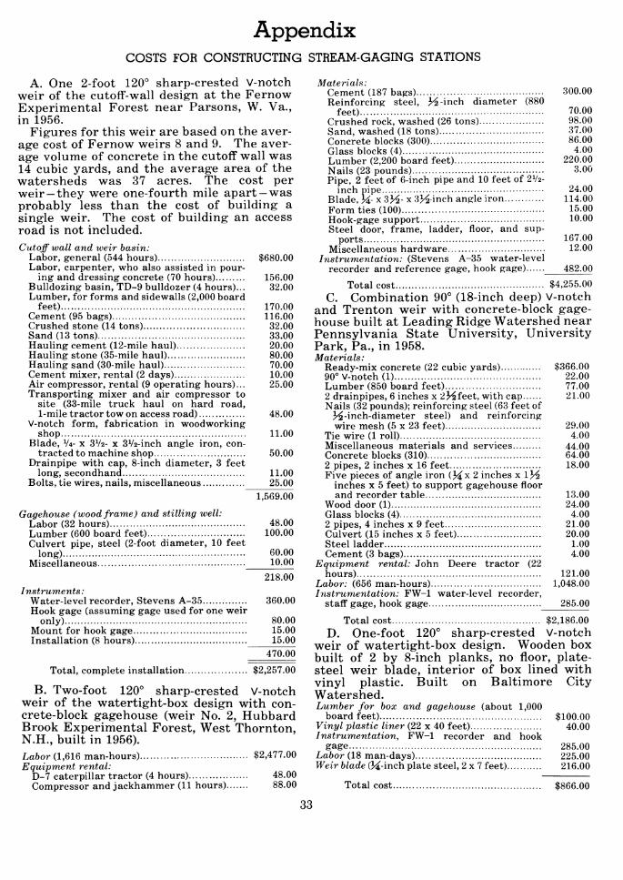
Appendix COSTS FOR CONSTRUCTING STREAM-GAGING STATIONS
A. One 2-foot 120° sharp-crested V-notch weir of the cutoff-wall design at the Fernow Experimental Forest near Parsons, W. Va., in 1956.
Figures for this weir are based on the aver- age cost of Fernow weirs 8 and 9. The aver- age volume of concrete in the cutoff wall was 14 cubic yards, and the average area of the watersheds was 37 acres. The cost per weir —they were one-fourth mile apart —was probably less than the cost of building a single weir. The cost of building an access road is not included. Cutoff wall and weir basin:
Labor, general (544 hours) $680.00 Labor, carpenter, who also assisted in pour-
ing and dressing concrete (70 hours) 156.00 Bulldozing basin, TD-9 bulldozer (4 hours)... 32.00 Lumber, for forms and sidewalls (2,000 board
feet) 170.00 Cement (95 bags) 116.00 Crushed stone (14 tons) 32.00 Sand (13 tons) 33.00 Hauling cement (12-mile haul) 20.00 Hauling stone (35-mile haul) 80.00 Hauling sand (30-mile haul) 70.00 Cement mixer, rental (2 days) 10.00 Air compressor, rental (9 operating hours)... 25.00 Transporting mixer and air compressor to
site (33-mile truck haul on hard road, 1-mile tractor tow on access road) 48.00
V-notch form, fabrication in woodworking shop 11.00
Blade, VA- X 3V2- x 3V2-inch angle iron, con- tracted to machine shop 50.00
Drainpipe with cap, 8-inch diameter, 3 feet long, secondhand 11.00
Bolts, tie wires, nails, miscellaneous 25.00 1,569.00
Gagehouse (wood frame) and stilling well: Labor (32 hours) 48.00 Lumber (600 board feet) 100.00 Culvert pipe, steel (2-foot diameter, 10 feet
long) 60.00 Miscellaneous 10.00
218.00 Instruments:
Water-level recorder, Stevens A-35 360.00 Hook gage (assuming gage used for one weir
only) 80.00 Mount for hook gage 15.00 Installation (8 hours) 15.00
470.00
Total, complete installation $2,257.00
B. Two-foot 120° sharp-crested V-notch weir of the watertight-box design with con- crete-block gagehouse (weir No. 2, Hubbard Brook Experimental Forest, West Thornton, N.H., built in 1956). La6or (1,616 man-hours) $2,477.00 Equipment rental:
D-7 caterpillar tractor (4 hours) 48.00 Compressor and jackhammer (11 hours) 88.00
Materials: Cement (187 bags) 300.00 Reinforcing steel, H-inch diameter (880
feet) 70.00 Crushed rock, washed (26 tons) 98.00 Sand, washed (18 tons) 37.00 Concrete blocks (300) 86.00 Glass blocks (4) 4.00 Lumber (2,200 board feet) 220.00 Nails (23 pounds) 3.00 Pipe, 2 feet of 6-inch pipe and 10 feet of 2V2-
inch pipe 24.00 Blade, H- x SH- x 3>^ inch angle iron 114.00 Form ties (100) 15.00 Hook-gage support 10.00 Steel door, frame, ladder, floor, and sup-
ports 167.00 Miscellaneous hardware 12.00
Instrumentation: (Stevens A-35 water-level recorder and reference gage, hook gage) 482.00
Total cost $4,255.00 C. Combination 90° (18-inch deep) V-notch
and Trenton weir with concrete-block gage- house built at Leading Ridge Watershed near Pennsylvania State University, University Park, Pa., in 1958. Materials:
Ready-mix concrete (22 cubic yards) $366.00 90° V-notch (1) 22.00 Lumber (850 board feet) 77.00 2 drainpipes, 6 inches x 2 J^feet, with cap 21.00 Nails (32 pounds); reinforcing steel (63 feet of
J^-inch-diameter steel) and reinforcing wire mesh (5 x 23 feet) 29.00
Tie wire (1 roll) 4.00 Miscellaneous materials and services 44.00 Concrete blocks (310) 64.00 2 pipes, 2 inches x 16 feet 18.00 Five pieces of angle iron (J^x 2 inches x IJ^
inches x 5 feet) to support gagehouse floor and recorder table 13.00
Wood door (1) 24.00 Glass blocks (4) 4.00 2 pipes, 4 inches x 9 feet 21.00 Culvert (15 inches x 5 feet) 20.00 Steel ladder 1.00 Cement (3 bags) 4.00
Equipment rental: John Deere tractor (22 hours) 121.00
Labor: (656 man-hours) 1,048.00 Instrumentation: FW-1 water-level recorder,
staff gage, hook gage 285.00
Total cost $2,186.00 D. One-foot 120° sharp-crested V-notch
weir of watertight-box design. Wooden box built of 2 by 8-inch planks, no floor, plate- steel weir blade, interior of box lined with vinyl plastic. Built on Baltimore City Watershed. Lumber for box and gagehouse (about 1,000
board feet) $100.00 Vinyl plastic liner (22 x 40 feet) 40.00 Instrumentation, FW-1 recorder and hook
gage 285.00 Labor (18 man-days) 225.00 Weir blade (Ji-inch plate steel, 2x7 feet) 216.00
Total cost $866.00
33

PARTIAL LIST OF STREAM-GAGING STATIONS BEING USED FOR RESEARCH ON SMALL WATERSHEDS IN THE UNITED STATES
Operating agency
Northeastern Forest périment Station (Upper Darby, Pa.).
Ex-
Southeastern Forest Ex- periment Station (Ashe- ville, N.C.).
Central States Forest Experiment Station (Co- lumbus, Ohio).
Lake States Forest Ex- periment Station (St. Paul, Minn.).
Southern Forest & Range Experiment Station (New Orleans, La.).
Rocky Mountain Forest & Range Experiment Sta- tion (Fort Collins, Colo.).
Location
Hubbard Brook Experimen- tal Forest, West Thorn- ton, N.H.
Fernow Experimental For- est, Parsons, W. Va.
Pocono Experimental For- est, Gouldsboro, Pa.
Dilldown watershed, Blakes- lee. Pa.
Baltimore (Md.) municipal watershed.
Newark (N.J.) municipal watershed.
Coweeta Hydrologie Labo- ratory, Franklin, N.C.
Piedmont Research Center, Union, S.C.
Dover, Ohio
LaCrosse, Wis.
Tallahatchie Research Center, Oxford, Miss.
Fraser Experimental For- est, Fraser, Colo.
Prescott National Forest, Arizona.
Front Range, near Fort Collins, Colo.
Type of gaging station
90° and 120° V-notch weirs, watertight-box design; combined 3-foot San Dimas flume and 90° V- notch.
120° V-notch weirs, cutoñ"- wall design.
Columbus deep-notch weir..
Columbus deep-notch weir..
120° V-notch weirs, con- crete-block walls, water- tight-box design.
120° V-notch weir, wooden box with vinyl plastic liner.
120° V-notch weirs, water- tight box.
90° V-notch weirs
120° V-notch weirs.
Rectangular weirs, crest length, 5-6 feet.
Cipolletti weirs, crest length, 6-8 feet.
Cipolletti weirs, crest length, 12 feet.
Columbus deep-notch weirs..
90° V-notch weirs 90° V-notch weir and 2-foot
San Dimas flume in tandem.
90° V-notch weirs, tem- porary).
90° V-notch weirs, con- crete-box type.
2-foot San Dimas flumes, fabricated steel.
H-type trapezoidal flumes, fabricated steel.
H-type flume, galvanized iron construction.
Combination San Dimas flume and rectangular weir with oriñce plate for low winter flows; combi- nation broad-crested trap- ezoidal weir with rectan- gular flume notched into center; 120° V-notch weir.
1-foot 120° V-notch weirs in series with San Dimas flumes; San Dimas flume.
2-foot San Dimas flume and 30-inch, 90° V-notch weirs.
Remarks
6 watersheds, 30 to 104 acres.
9 watersheds, 29 to 96 acres.
1 watershed, 560 acres.
1 watershed, 1,530 acres; in cooperation with Pa. Dept. of Forests and Waters and U.S. Geol. Survey.
3 watersheds, 26 to 48 acres; in cooperation with City of Baltimore.
3 watersheds, 24 to 68 acres; in cooperation with City of Newark.
5 watersheds, 22 to 50 acres.
11 watersheds, 31 to 212 acres.
4 watersheds, 350 to 943 acres; not currently in operation.
2 watersheds, 501 and 940 acres; not currently in operation.
2 watersheds, 1,788 and 1,877 acres.
2 watersheds, , 23 and 145 acres; weir on larger watershed not currently in operation.
3 watersheds, 15 to 22 acres. 1 watershed, 13 acres.
2 watersheds, 18 and 23 acres; on land of Mus- kingum Conserv. Dist.
Spring-fed stream.
Storm runoff" only.
Do.
Mostly for storm runoff".
Velocity head rod used to check rating.
34

PARTIAL LIST OF STREAM-GAGING STATIONS BEING USED FOR RESEARCH ON SMALL WATERSHEDS IN THE UNITED STATES—Continued
Operating agency
Location Type of gaging station Remarks
Rocky Mountain Forest & Range Experiment Sta- tion (Fort Collins, Colo.) (Continued).
Intermountain Forest & Range Experiment Sta- tion (Ogden, Utah).
Pacific Northwest Forest & Range Experiment Sta- tion (Portland, Oreg.).
Pacific Southwest Forest & Range Experiment Sta- tion (Berkeley, Calif.).
Castle Creek, Willow Creek, and Thomas Creek, near Beaverhead, Ariz.
Campbell Blue, near Apline, Ariz.
Sage Brush watersheds, near Dubois, Wyo.
3-Bar watersheds, near Roosevelt, Ariz.
Natural drainages. Sierra Ancha Experimental For- est, Ariz.
Parker & Pocket Creeks, Sierra Ancha Experimen- tal Forest, Ariz.
Workman Creek, Sierra Ancha Experimental For- est, Ariz.
Black Mesa, Near Grand Junction, Colo.
Beaver Creek, near Pres- cott, Ariz.
Dog Creek Watersheds, near Reno, Nev.
Davis County Experimental Watershed, near Farm- ington, Utah.
Parrish Creek, near Farm- ington, Utah.
Great Basin Research Cen- ter, near Ephraim, Utah.
Tailholt Creek, Payette Na- tional Forest, Idaho.
Benton Creek, Priest River Experimental Forest, near Priest River, Idaho.
H. J. Andrews Experimen- tal Forest, near McKenzie Bridge, Oreg. (Corvallis Research Center).
Bull Run watershed, near Portland, Oreg.
South Umpqua Experimen- tal Forest, near Tiller, Oreg.
Entiat Watersheds, near Portland, Oreg.
San Dimas Experimental Forest, Glendora, Calif.
Teakettle Experimental Forest, near Fresno, Calif.
Onion Creek Experimental Forest,near Soda Springs, Cahf.
5 weirs, 120° V-notch, 3-foot head.
Villemonte Sill in culvert—
3 V-notch weirs, 120°
4 V-notch weirs, 90° and 120°
4 V-notch weirs, 90°
Wooden cutoff walls..
Concrete-block dams.
Combination Cipolletti and 90° V-notch weirs.
2 V-notch weirs, 1 trape- zoidal flume, 1 combina- tion Cipolletti and V-notch weir.
3 V-notch weirs, 120°
14 modified trapezoidal flumes.
Combination broad-crested 120° V-notch weirs.
Modified Venturi trapezoi- dal flumes.
0-Gee control section
Self-cleaning flumes 90° and 120° V-notch weirs. 120° V-notch weir
Self-cleaning flume; 120° V- notch weirs.
0-Gee control section
2 Cipolletti weirs.
Trapezoidal flumes.
Trapezoidal flumes.
120° V-notch weirs.
120° V-notch weirs, 3 feet high.
Combination 90° V-notch weir and 3- and 10-foot flumes.
Combination 90° V-notch weir and 6-foot Cipolletti weir.
120° V-notch weirs
Some in combination with V- notch; flume has capacity of 0.5 to 300 c.f.s.
Operated in cooperation with U.S. Geol. Survey.
In planning stage.
In cooperation with Payette National Forest, Idaho.
3 watersheds, 149 to 250 acres; rated by velocity head rod.
3 watersheds, 150 to 300 acres; rated by velocity head rod; in cooperation with City of Portland.
2 watersheds, average 150 acres.
3 watersheds, concrete-block weir construction, 500 to 1,000 acres.
Watersheds range from 70 to 550 acres; operated in cooperation with U.S. Geol. Survey.
Watersheds range from 120 to 560 acres; operated in cooperation with U.S. Geol. Survey.
35

PARTIAL LIST OF STREAM-GAGING STATIONS BEING USED FOR RESEARCH ON SMALL WATERSHEDS IN THE UNITED STATES—Continued
Operating agency
Location Type of gaging station Remarks
Pacific Southwest Forest & Castle Creek Experimental Area, near Soda Springs, Calif.
Sagehen Experimental Area near Hobart Mills, Calif.
Yuba Gap Experimental Area, near Sierraville, Calif.
Young Bay, Admiralty Is- land, Alaska.
Cohocton, N.Y.
Parshall flume 1 watershed, 4 square miles; Range Experiment Sta- tion (Berkeley, Calif.)- Continued. Variable-notch weir
operated in cooperation with U.S. Geol. Survey.
1 watershed, 11 square miles;
Rated section
gaging by U.S. Geol. Survey.
1 watershed, 7.6 square miles; gaging by Calif. Dept. of Water Resources.
2 watersheds, 2,500 and 3,000 acres.
Switzer Creek Watershed
Alaska Forest Research Broad-crested weirs Center (Juneau, Alaska).
Agricultural Research 1:10 broad-crested V-notch weir.
1:10 and 1:2 broad-crested V-notch weirs.
H-type flumes
Service (stations oper- ated by Soil and Water Dutchess County, N.Y
2,215 acres. Millbrook school, 76 to 1,570
acres. Conservation Research Division except as noted College Park, Md in remarks). Watkinsville, Ga 1:5 broad-crested V-notch
weir. H-type flumes; 1:2 broad-
crested V-notch weir; rec- tangular culverts with Virginia V-notch low-flow controls.
1:5 broad-crested V-notch weirs.
H-tvne flumes
1 drainage area, 19 acres.
Culvert stations at widely dispersed watersheds; drainage areas, 185 to 2,000 acres.
2 drainage areas, 46 and 82 acres. Operated by Agr. Engin. Dept., Univ. of Illinois.
Operated by Michigan Agr. Expt, Sta.
Drainage areas of 1 to 17,500 acres.
4 drainage areas, about 10 acres each.
23- to 330-acre drainage areas.
About 3-acre drainage areas.
Blacksburg, Va
Monticello, 111
East Lansing, Mich
Coshocton, Ohio Dual Parshall flumes, with 15-foot main throat and 1- foot low-flow throat; Co- lumbus deep-notch low- flow control at current meter-rated section; 1:5 broad-crested V-notch weirs; H-type flumes of several sizes.
4.5-foot H-type flumes Agricultural Research Service (Continued).
Moorefield, W Va
Fennimore. Wis 1:3 and 1:5 broad-crested V- notch weirs.
Trapezoidal flumes LaCrosse. Wis Colbv, Wis 1:5 broad-crested V-notch
weir 1 drainage area, 345 acres.
Stillwater, Okla Rectangular highway cul- verts equipped with weir sill for low-flow measure- ment.
H-type flumes
16- to 206-acre drainage areas.
About 5-acre drainage areas.
Drainage areas of 3 to 4,400 acres.
Drainage areas of 3 to 4,400 acres.
Drainage areas of about 700 acres.
Drainage areas, 360 to 28,100 acres; capacity of largest flume, about 18,000 c.f.s.
Drainage areas, 40 to 170 acres.
Cherokee, Okla
Riesel, Tex 15-, 10-, and 6-foot Parshall flumes with Columbus deep-notch low-flow con- trol; Columbus deep-notch low-flow control at cur- rent meter-rated section; H-type flumes.
1:3 broad-crested V-notch weirs for low-flow control at current meter-rated sections; H-type flumes.
1:3 and 1:5 broad-crested V- notch weirs.
Tombstone critical-depth flumes.
1:3 broad-crested V-notch weirs.
Hastings, Nebr
S afford, Ari z
Tombstone, Ariz
Albuquerque, N. Mex
36

PARTIAL LIST OF STREAM-GAGING STATIONS BEING USED FOR RESEARCH ON SMALL WATERSHEDS IN THE UNITED STATES—Continued
Operating: agency
Location
Agricultural Research Service (Continued).
School of Forestry, Penn State University (Uni- versity Park, Pa.).
U.S. Geological Survey..
Tennessee Valley Authority (Knoxville, Tenn.).
Santa Rosa, N. Mex
Oxford, Miss
Newell, S. Dak
Danville, Vt
Leading Ridge Watersheds and Shale Hills Water- sheds, near State College, Pa.
Tar Hollow State Park, Ohio.
Lebanon State Forest, New Jersey.
White Hollow Watershed, Union County, Tenn.
Pine Tree Branch, near Lexington, Tenn.
Parker Branch Research Watershed, near Ashe- ville, N.C.
Western North Carolina Research Watersheds, near Waynesville and Asheville, N.C.
North Citico Creek, near TelHco Plains, Tenn.
Type of gaging station
Tombstone critical-depth flume.
Current meter-rated sta- tions; H-type flumes; trap- ezoidal flumes.
Water-level recorders on large-capacity stock ponds.
1:10, 1:5, and 1:3 broad- crested V-notch weirs; current meter-rated sec- tion.
Combination 90° V-notch and Trenton control weirs; combination 4.5- foot H-type flume with sharp-crested 60° V-notch weir; composite 30°-150° sharp-crested V-notch weir; sharp-crested para- bolic-notch weir.
V-notch weir, wide-angle, broad-crested, rated. Trenton-type weirs
Modified Albany weir..
Columbus deep-notch weir.
Modified Albany weir
2-foot H-type flumes; le foot San Dimas flumes.
Rectangular weir, 66 feet long by 3 feet deep, with low-water section, 10 feet by 1 foot.
Remarks
1 drainage area, 42,900 acres; capacity of flume about 18,000 c.f.s.
Flumes on areas of less than 5 acres; current meter- rated stations, 100 acres to 117 square miles.
Drainage areas of 30 to 1,110 acres.
Drainage areas of 150 to 27,500 acres.
watersheds, 25 to 300 acres; in cooperation with Pa. Dept. of Forests and Waters and Northeast. Forest Expt. Sta.
1 forested watershed, 1.5 square miles.
2 watersheds, about 1,500 acres each; in cooperation with N.J. Dept. of Conserv. and Econ. Devlpmt. and Rutgers Univ.
1 watershed, 2.68 square miles; calibrated in TVA laboratory.
1 watershed, 88.2 acres.
1 watershed, 966 acres; in cooperation with North Carolina State Col.
4 watersheds, 3.7 to 5.6 acres; in cooperation with North Carolina State Col.
1 watershed, 7.04 square- miles; in cooperation with U.S. Forest Service.
U.S. GOVERNMENT PRINTING OFFICE : 1964 OL—717-764
37