Embed Size (px)
Citation preview
Infrastructure and Network Design Guide
StreamNetINfraStructure aNd Network deSIgN guIde
CLEARONE PART NO. 800-000-045 APRIL 21, 2011 (REV. 1.0)
© 2011 ClearOne and NetStreams - All rights reserved. No part of this document may be reproduced in any form or by any means without written permission from ClearOne and NetStreams. Printed in the United States of America. ClearOne and NetStreams reserves specific privileges.
Information in this document is subject to change without notice.
U.S. PATENTS:
US 7,643,894US 7,711,126
INTErNATIoNAl PATENTS:
Australia 2003-241405Korean 10-2004-7017970
oTHEr PATENTS PENDING
US 11/467,340US 11/960,401US 12/015,385US 12/418,267US 12/472,976US 12/727,925US 12/761,506US 12/900,666US 12/917,765US 12/917,773European 03731139.6European 06251345.2Canadian 2,485,104Canadian 2,539,458Australia 2008-207498
Telephone 1.800.283.5936 1.801.974.3760
Tech Sales 1.800.705.2103
FAX 1.801.974.3669
E-mail [email protected] [email protected]
On the Web www.clearone.com www.netstreams.com www.streamnetpartners.com
ChAPTER 1: STREAmNET NETWORkING .......................................................... 1StreamNet Networking Guide ...............................................................................1StreamNet vs other AV Networks .........................................................................1Streamnet Networking Concepts ..........................................................................2routers ..................................................................................................................3Default Gateway ....................................................................................................3IP Addressing ........................................................................................................3
Defining and Managing IP Addresses and Subnets .......................................3IP Address ranges ................................................................................................4WAP .......................................................................................................................5Uplink Port .............................................................................................................5IGMP ......................................................................................................................7PoE Power over Ethernet (DC to DC injection) .....................................................7For VlAN Use Cases .............................................................................................8
ChAPTER 2: SWITCh CONFIGuRATION SETTINGS ........................................ 11NetStreams, Clearone and Dell Branded Switches ...........................................115424 - 5448 Implementation ................................................................................11
Firmware and Boot Codes .............................................................................11Dell 5424 - 5448 Switch Settings ...................................................................11Access Ports ..................................................................................................11Switch Uplinks ................................................................................................11Best Practices ................................................................................................11
Dell 5424 - 5448 ClI Commands for Configuring the Services ..........................126224-6248 Implementation ..................................................................................13Dell 6224 - 6248 Switch Settings .........................................................................13
Access Ports ..................................................................................................13Switch Uplinks ................................................................................................13Best Practices ................................................................................................13
Dell 6224 - 6248 ClI Commands for Configuring the Services ..........................13Non-Netsreams or Clearone branded Implementation ......................................15StreamNet Generic QoS Switch requirements recommendations ..................15
requirements for Audio only StreamNet Applications .................................15requirements for loss-less or MotionTX Audio/Video StreamNet Applications .................................................................................15Additional StreamNet requirements for Global and VlAN Applications ......15StreamNet Access Point requirements ........................................................15StreamNet Switch Uplinks requirements .....................................................15StreamNet Infrastructure Best Practices .......................................................15
table of coNteNtS
Chapter 1: StreamNet Networking 1
ChAPTER 1: STREAmNET NETWORkING
STREAmNET NETWORkING GuIDEStreamNet is a third-generation networked AV media and control technology that provides the highest quality audio and video signaling and controls with unmatched scalability when compared to other networking and legacy AV distribution technologies. StreamNet was designed to work over Internet Protocol, and hence can be deployed over many networking topologies and infrastructures such as fiber, UTP, power line or even wireless with the proper QoS. StreamNet system designs are flexible and can co-exist with other networking traffic and can be used in deployments with one or more routers, or any number of VLAN’s where necessary.
StreamNet allows your network to be shared between audio video distribution, controls and traditional PC applications. No need for multiple data infrastructures or expensive proprietary infrastructure requirements. Most commercial and enterprise buildings in the United States are already equipped with the necessary networking hardware to deploy a StreamNet solution.
This guide was intended to provide the basic requirements needed to ensure a reliable Quality of Service (QoS) for any StreamNet deployment. The vast majority of all StreamNet systems in place today utilize standard commodity gigabit Ethernet or Fast Ethernet as the infrastructure and most are provisioned on a single LAN.
StreamNet has no limit to the total number of sources, displays or control points connected to the network. The network infrastructure needs to be designed and configured appropriately to accommodate your needs and specification.
StreamNet is synchronized to within 1 ms anywhere on the network. This time precision is assured by a high-performance hardware-assisted StreamNet time protocol. All StreamNet audio processing is sonically transparent and the high quality 24-bit DAC and 24-bit ADC used throughout encoding and decoding are designed to ensure high quality audio and preserves dynamic range.
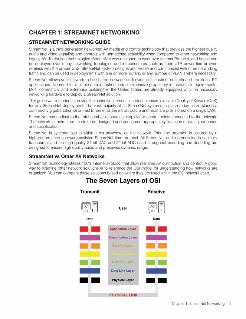
StreamNet vs Other AV NetworksStreamNet technology utilizes 100% Internet Protocol that allow real time AV distribution and control. A good way to examine other network solutions is to reference the OSI model for understanding how networks are organized. You can compare these solutions based on where they are used within the OSI network chart.
The Seven Layers of OSI
User
Application Layer
Presentation Layer
Session Layer
Transport Layer
Network Layer
Data Link Layer
Physical Layer
Transmit
Data
Receive
Data
PHYSICAL LINK
2 TechSales StreamNet Design help: 1.800.705.2103
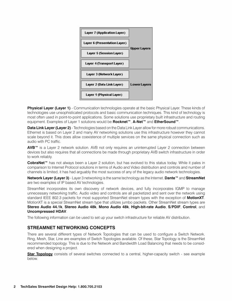
Physical Layer (Layer 1) - Communication technologies operate at the basic Physical Layer. These kinds of technologies use unsophisticated protocols and basic communication techniques. This kind of technology is most often used in point-to-point applications. Some solutions use proprietary built infrastructure and routing equipment. Examples of Layer 1 solutions would be Rocknet™, A-Net™ and EtherSound™.
Data Link Layer (Layer 2) - Technologies based on the Data Link Layer allow for more robust communications. Ethernet is based on Layer 2 and many AV networking solutions use this infrastructure however they cannot scale beyond it. This does allow coexistence of multiple services on the same physical connection such as audio with PC traffic.
AVB™ is a Layer 2 network solution. AVB not only requires an uninterrupted Layer 2 connection between devices but also requires that all connections be made through proprietary AVB switch infrastructure in order to work reliably.
CobraNet™ has not always been a Layer 2 solution, but has evolved to this status today. While it pales in comparison to Internet Protocol solutions in terms of Audio and Video distribution and controls and number of channels is limited, it has had arguably the most success of any of the legacy audio network technologies.
Network Layer (Layer 3) - Layer 3 networking is the same technology as the Internet. Dante™ and StreamNet are two examples of IP based AV technologies.
StreamNet incorporates its own discovery of network devices, and fully incorporates IGMP to manage unnecessary networking traffic. Audio video and controls are all packetized and sent over the network using standard IEEE 802.3 packets for most supported StreamNet stream types with the exception of motionXT. MotionXT is a special StreamNet stream type that utilizes jumbo packets. Other StreamNet stream types are Stereo Audio 44.1k, Stereo Audio 48k, mono Audio 48k, high-bit-rate Audio, S/PDIF, Control, and uncompressed hDAV.
The following information can be used to set up your switch infrastructure for reliable AV distribution.
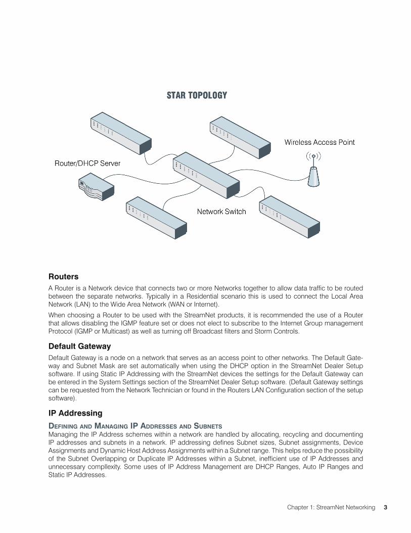
STREAmNET NETWORkING CONCEPTSThere are several different types of Network Topologies that can be used to configure a Switch Network. Ring, Mesh, Star, Line are examples of Switch Topologies available. Of these, Star Topology is the StreamNet recommended topology. This is due to the Network and Bandwidth Load Balancing that needs to be consid-ered when designing a project.
Star Topology consists of several switches connected to a central, higher-capacity switch - see example below.
Chapter 1: StreamNet Networking 3
RoutersA Router is a Network device that connects two or more Networks together to allow data traffic to be routed between the separate networks. Typically in a Residential scenario this is used to connect the Local Area Network (LAN) to the Wide Area Network (WAN or Internet).
When choosing a Router to be used with the StreamNet products, it is recommended the use of a Router that allows disabling the IGMP feature set or does not elect to subscribe to the Internet Group management Protocol (IGMP or Multicast) as well as turning off Broadcast filters and Storm Controls.
Default GatewayDefault Gateway is a node on a network that serves as an access point to other networks. The Default Gate-way and Subnet Mask are set automatically when using the DHCP option in the StreamNet Dealer Setup software. If using Static IP Addressing with the StreamNet devices the settings for the Default Gateway can be entered in the System Settings section of the StreamNet Dealer Setup software. (Default Gateway settings can be requested from the Network Technician or found in the Routers LAN Configuration section of the setup software).
IP Addressing
defININg aNd maNagINg IP addreSSeS aNd SubNetSManaging the IP Address schemes within a network are handled by allocating, recycling and documenting IP addresses and subnets in a network. IP addressing defines Subnet sizes, Subnet assignments, Device Assignments and Dynamic Host Address Assignments within a Subnet range. This helps reduce the possibility of the Subnet Overlapping or Duplicate IP Addresses within a Subnet, inefficient use of IP Addresses and unnecessary compllexity. Some uses of IP Address Management are DHCP Ranges, Auto IP Ranges and Static IP Addresses.
4 TechSales StreamNet Design help: 1.800.705.2103
Dynamic host Configuration Protocol (DhCP) is an auto configuration protocol that assigns IP Addresses to devices connected a network segment requesting the DHCP protocol. This is a very efficient way to assign IP Addresses within a defined Subnet. DHCP will automatically assign, recycle and maintain the IP Addresses allowed by the DHCP Server settings. This is the default for all StreamNet devices, if the StreamNet device fails to locate a suitable DHCP server it will then change to an Auto IP mode.
Static IP addressing is a method in which every device is given a specific controlled IP Address on the network. This method ensures that the device IP Address will not overlap or conflict with other IP Addresses in the network. This method requires a great deal recording, tracking and managing assigned IP Addresses to ensure a duplicate Address is not assigned within the Subnet. Typically used when an IP Range would consume too many available IP Addresses.
NOTE: There is no assurance that another device with a static IP address will not overlap.
Auto IP is a module that allows for the Automatic assignment of an IP Address to devices on the network within a given range without the use of a DHCP server. Much like the DHCP protocol, Auto IP allows for a de-vice to receive an IP Address automatically on startup.
Default Auto IP settings in StreamNet Dealer Setup software:
DigiLinXealer Setup 2.56 and earlier versions
Auto IP Range: 10.15.0.1 – 10.15.255.255, Subnet Mask: 255.0.0.0
Default Gateway: 0.0.0.0, DHCP: Not in Use
StreamNet Dealer Setup 2.60.04 and later versions
Auto IP Range: 169.254.1.0 – 169.254.254.255, Subnet Mask: 255.255.0.0
Default Gateway: 0.0.0.0, DHCP: On by Default
IP Address RangesClass A comprises networks 1.0.0.0 through 127.0.0.0. The network number is contained in the first octet. This class provides for a 24-bit host part, allowing roughly 1.6 million hosts per network.
Class B contains networks 128.0.0.0 through 191.255.0.0; the network number is in the first two octets. This class allows for 16,320 nets with 65,024 hosts each.
Class C networks range from 192.0.0.0 through 223.255.255.0, with the network number contained in the first three octets. This class allows for nearly 2 million networks with up to 254 hosts.
Classes D, E, and F
Addresses falling into the range of 224.0.0.0 through 254.0.0.0 are either experimental or are reserved for special purpose use and don’t specify any network. IP Multicast, which is a service that allows material to be transmitted to many points on an internet at one time, has been assigned addresses from within this range.
IP Address Ranges Reserved for Private use
CLASS NETWORkS
A 10.0.0.0 through 10.255.255.255
B 172.16.0.0 through 172.31.0.0
C 192.168.0.0 through 192.168.255.0
D 224.0.0.0 thought 139.0.0.0
Chapter 1: StreamNet Networking 5
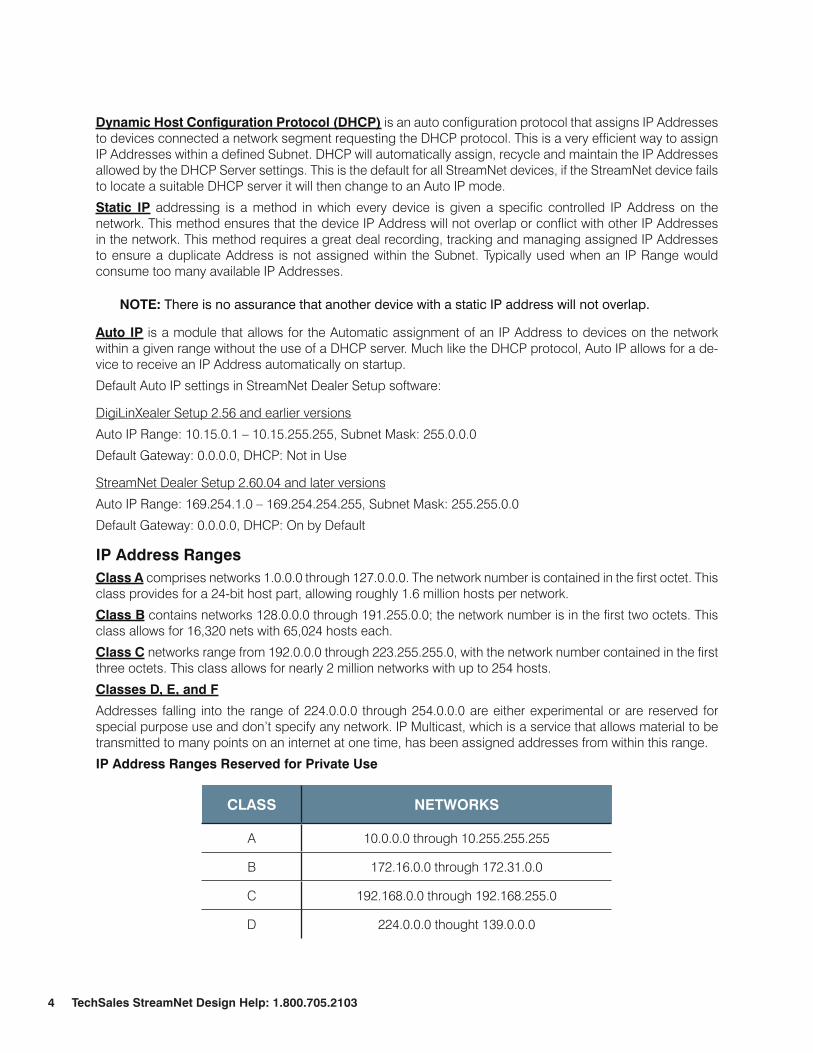
WAPWireless Access Point (WAP) is a Network device that allows Wireless devices access to a connected network via WiFi, Bluetooth and other related standards. A WAP is typically used in conjunction with a Router on the Network to supply the DHCP Server for Automatic IP Address Assignment (A Router is not required in this scenario, Static IP Addresses can be used to allow devices on a Network to communicate with a WAP setup). Some Wireless Routers work both as a Network Router and Gateway as well as the Wireless Access Point. When a Wireless setup is to be used with the StreamNet devices, the WiFi access is for 3rd party devices only (not the StreamNet devices). Many currently shipping StreamNet devices will not work on a wireless seg-ment or Wireless Bridge, these StreamNet devices must be directly connected to the Master or Slave switches. When choosing a Router to be used with the StreamNet products, it is recommended using a Router capable of disabling the IGMP feature set or does not elect to subscribe to the Internet Group management Proto-col (IGmP or multicast) as well as turning off Broadcast filters and Storm Controls.
uplink PortNetwork uplink Ports are used to link the network switches and create the backbone of the system. When creating the design for the network, it needs to be understood that all transmitted data will have to flow through these links. If the sources on the network requires a maximum of 50MB, a 100MB uplink will be adequate. But if the A/V devices are streaming video at a high data rate or uncompressed, then you will need 1000MB links or even 10G links. In large systems especially, it is recommended using fiber links to allow for the increased bandwidth usage. In this case, Switch Stacking or a fiber-connected solution may be needed to facilitate the system bandwidth requirements.
6 TechSales StreamNet Design help: 1.800.705.2103
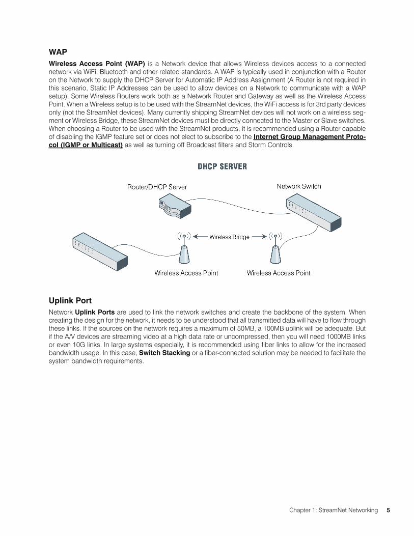
StreamNet Stream formatS
SIGNAL TyPE STREAm TyPE NAmE COmPRESSION mODE DATA RATE
Mono Audio ProStream A Uncompressed 1 Mb/s
Stereo Audio StreamNet ST Uncompressed 2 Mb/s
S/PDIF StreamNet DA Uncompressed 2 - 10 Mb/s
SD / HD Video StreamNet DV Uncompressed 50 - 880 Mb/s
SD / HD Video MotionXT Live / Cinema 5 5 Mb/s
SD / HD Video MotionXT Live / Cinema 15 15 Mb/s
SD / HD Video MotionXT Live / Cinema 30 30 Mb/s
SD / HD Video MotionXT Live / Cinema 45 45 Mb/s
SD / HD Video MotionXT Live / Cinema 60 60 Mb/s
SD / HD Video MotionXT Live / Cinema 90 90 Mb/s
SD / HD Video StreamNet 264SVC Live / Cinema 264 1 - 5 Mb/s
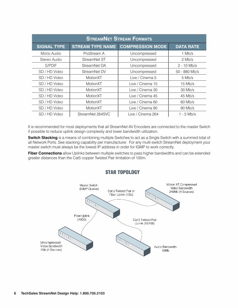
It is recommended for most deployments that all StreamNet AV Encoders are connected to the master Switch if possible to reduce uplink design complexity and lower bandwidth utilization.
Switch Stacking is a means of combining multiple Switches to act as a Single Switch with a summed total of all Network Ports. See stacking capability per manufacturer. For any multi-switch StreamNet deployment your master switch must always be the lowest IP address in order for IGMP to work correctly.
Fiber Connections allow Uplinks between multiple switches to pass higher bandwidths and can be extended greater distances than the Cat5 copper Twisted Pair limitation of 100m.
Chapter 1: StreamNet Networking 7
IGmPIGmP is a multicast group discovery protocol that is used between the clients and the local multicast router.
Multicast enables efficient use of network bandwidth, as each multicast datagram needs to be transmitted only once on each network link, regardless of the number of destination hosts.
Hosts must have a way to identify their interest in joining any particular multicast group, and routers must have a way to collect and maintain group memberships: these functions are handled by the IGMP protocol in IPv4. In IPv6, multicast routers use the multicast Listener Discover (mLD) protocol to maintain group member-ship information.
Multicast routers must also be able to create a multicast distribution tree that enables forwarding of Multicast Datagrams only on the links that are required to reach a destination group member.
PIm-Sm, PIm-Dm, and DVmRP are multicast routing protocols that are used across different subnets, usually between the local multicast router and remote multicast router.
PIm Protocol Independent multicast (PIm) is a standard multicast routing protocol that provides scalable inter-domain multicast routing across the Internet, independent of the mechanisms provided by any particular Unicast routing protocol.
PIM has two types: PIM-Dense Mode (PIM-DM) and PIM-Sparse Mode (PIM-SM)
PoE Power over Ethernet (DC to DC injection)Power over Ethernet (PoE) is a technology that passes electrical power with the data on standard Ethernet ca-bling. Many StreamNet devices can utilize simple PoE injectors that will allow users to install devices with only a standard cat5 UTP cable. This is useful if the device has been installed in a location without any additional wire or without any access to local AC electrical service.
The way this works is you connect one power injector at the head-end close to the switch location. You con-nect one cat5 from the switch to the injector and then a second cat5 that would be used to connect the injector located by the switch with the injector at the far end of the cable located by the StreamNet device. Next you connect a power supply to the injector installed at the switch location. Finally you would connect another injector to the cat5 at the far end of the cable by the StreamNet device, and connect the power output to the StreamNet power input connection.
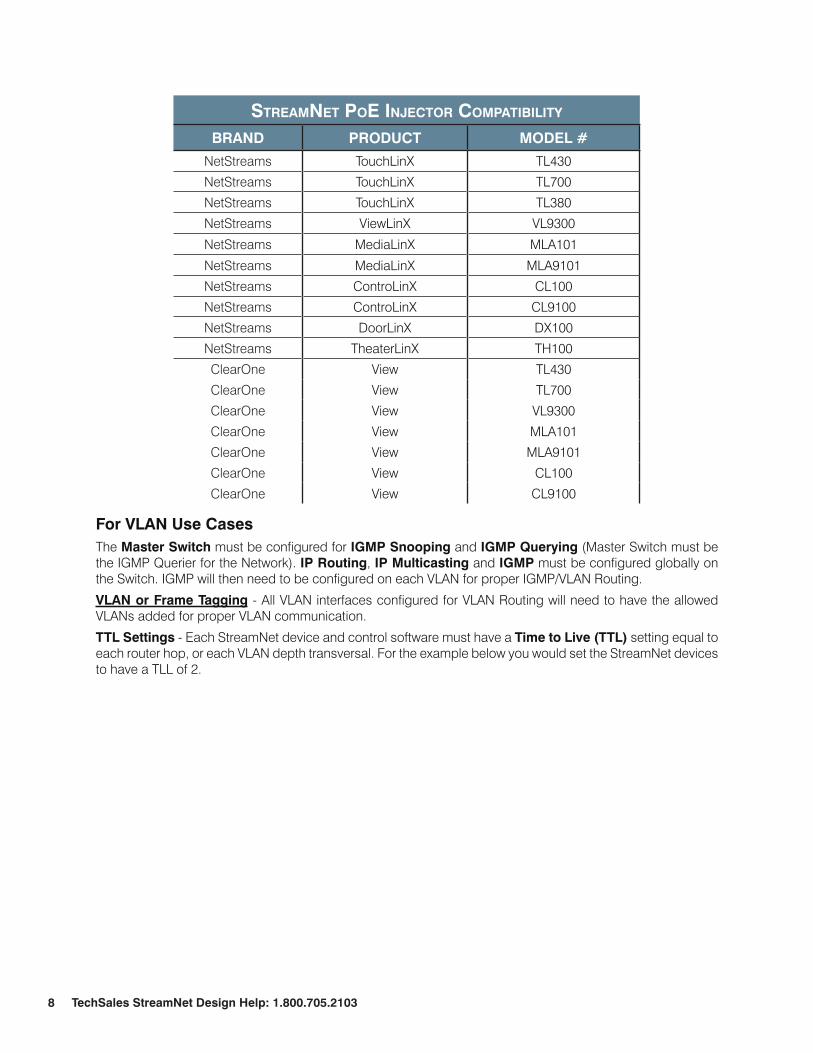
The following is a list of Current StreamNet devices that are PoE injector compatible:
8 TechSales StreamNet Design help: 1.800.705.2103
StreamNet Poe INjector comPatIbIlIty
BRAND PRODuCT mODEL #
NetStreams TouchLinX TL430
NetStreams TouchLinX TL700
NetStreams TouchLinX TL380
NetStreams ViewLinX VL9300
NetStreams MediaLinX MLA101
NetStreams MediaLinX MLA9101
NetStreams ControLinX CL100
NetStreams ControLinX CL9100
NetStreams DoorLinX DX100
NetStreams TheaterLinX TH100
ClearOne View TL430
ClearOne View TL700
ClearOne View VL9300
ClearOne View MLA101
ClearOne View MLA9101
ClearOne View CL100
ClearOne View CL9100
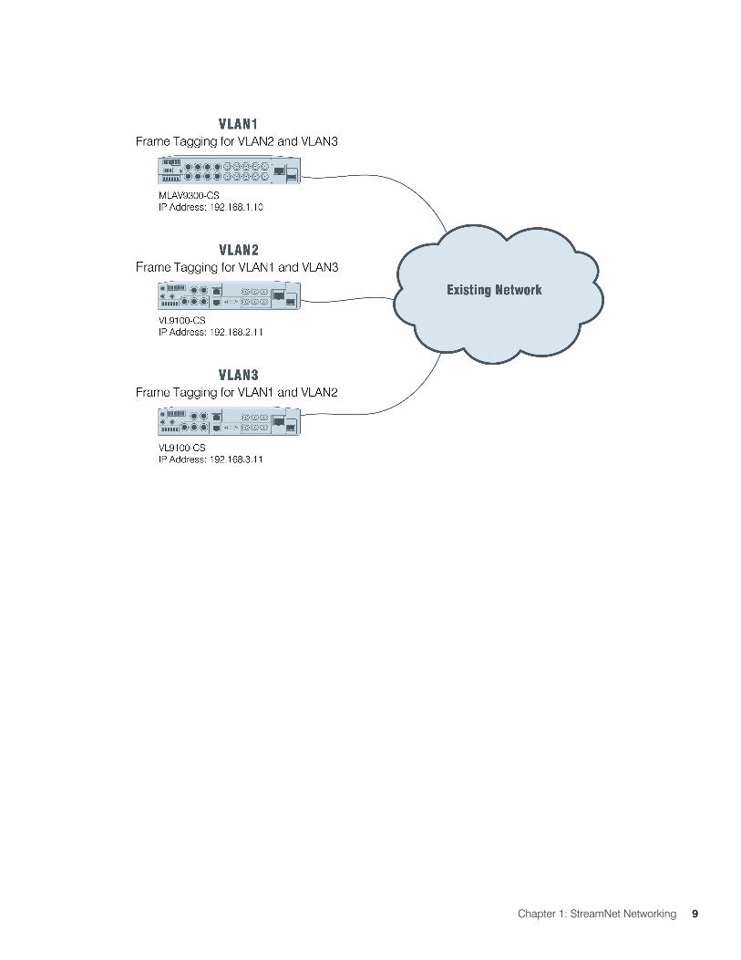
For VLAN use CasesThe master Switch must be configured for IGmP Snooping and IGmP Querying (Master Switch must be the IGMP Querier for the Network). IP Routing, IP multicasting and IGmP must be configured globally on the Switch. IGMP will then need to be configured on each VLAN for proper IGMP/VLAN Routing.
VLAN or Frame Tagging - All VLAN interfaces configured for VLAN Routing will need to have the allowed VLANs added for proper VLAN communication.
TTL Settings - Each StreamNet device and control software must have a Time to Live (TTL) setting equal to each router hop, or each VLAN depth transversal. For the example below you would set the StreamNet devices to have a TLL of 2.
Chapter 1: StreamNet Networking 9

10 TechSales StreamNet Design help: 1.800.705.2103
Chapter 2: Switch configuration Settings 11
ChAPTER 2: SWITCh CONFIGuRATION SETTINGS
NETSTREAmS, CLEARONE AND DELL BRANDED SWITChES
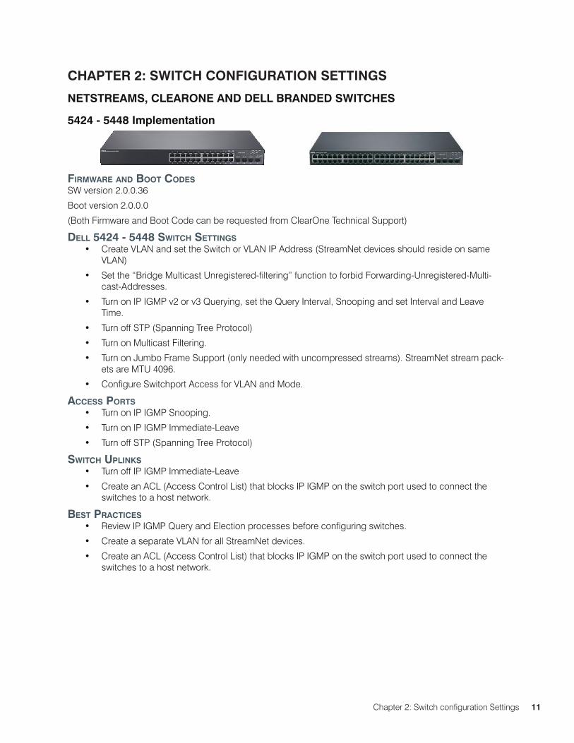
5424 - 5448 Implementation
fIrmware aNd boot codeSSW version 2.0.0.36
Boot version 2.0.0.0
(Both Firmware and Boot Code can be requested from ClearOne Technical Support)
dell 5424 - 5448 SwItch SettINgSCreate VLAN and set the Switch or VLAN IP Address (StreamNet devices should reside on same •VLAN)
Set the “Bridge Multicast Unregistered-filtering” function to forbid Forwarding-Unregistered-Multi-•cast-Addresses.
Turn on IP IGMP v2 or v3 Querying, set the Query Interval, Snooping and set Interval and Leave •Time.
Turn off STP (Spanning Tree Protocol)•
Turn on Multicast Filtering.•
Turn on Jumbo Frame Support (only needed with uncompressed streams). StreamNet stream pack-•ets are MTU 4096.
Configure Switchport Access for VLAN and Mode.•
acceSS PortSTurn on IP IGMP Snooping.•
Turn on IP IGMP Immediate-Leave•
Turn off STP (Spanning Tree Protocol)•
SwItch uPlINkSTurn off IP IGMP Immediate-Leave•
Create an ACL (Access Control List) that blocks IP IGMP on the switch port used to connect the •switches to a host network.
beSt PractIceSReview IP IGMP Query and Election processes before configuring switches.•
Create a separate VLAN for all StreamNet devices.•
Create an ACL (Access Control List) that blocks IP IGMP on the switch port used to connect the •switches to a host network.
12 TechSales StreamNet Design help: 1.800.705.2103
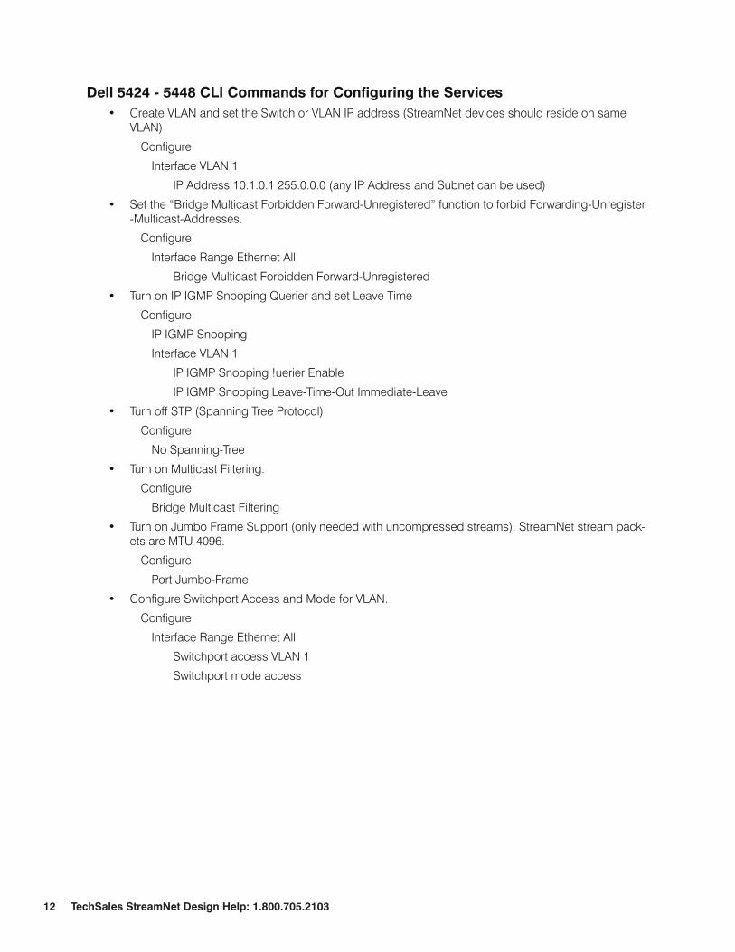
Dell 5424 - 5448 CLI Commands for Configuring the ServicesCreate VLAN and set the Switch or VLAN IP address (StreamNet devices should reside on same •VLAN)
Configure
Interface VLAN 1
IP Address 10.1.0.1 255.0.0.0 (any IP Address and Subnet can be used)
Set the “Bridge Multicast Forbidden Forward-Unregistered” function to forbid Forwarding-Unregister •-Multicast-Addresses.
Configure
Interface Range Ethernet All
Bridge Multicast Forbidden Forward-Unregistered
Turn on IP IGMP Snooping Querier and set Leave Time•
Configure
IP IGMP Snooping
Interface VLAN 1
IP IGMP Snooping !uerier Enable
IP IGMP Snooping Leave-Time-Out Immediate-Leave
Turn off STP (Spanning Tree Protocol)•
Configure
No Spanning-Tree
Turn on Multicast Filtering.•
Configure
Bridge Multicast Filtering
Turn on Jumbo Frame Support (only needed with uncompressed streams). StreamNet stream pack-•ets are MTU 4096.
Configure
Port Jumbo-Frame
Configure Switchport Access and Mode for VLAN.•
Configure
Interface Range Ethernet All
Switchport access VLAN 1
Switchport mode access
Chapter 2: Switch configuration Settings 13
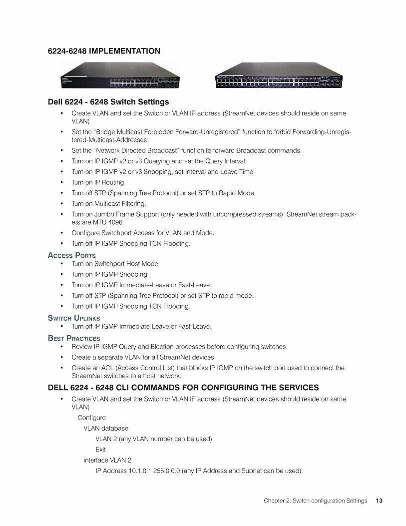
6224-6248 ImPLEmENTATION
Dell 6224 - 6248 Switch SettingsCreate VLAN and set the Switch or VLAN IP address (StreamNet devices should reside on same •VLAN)
Set the “Bridge Multicast Forbidden Forward-Unregistered” function to forbid Forwarding-Unregis-•tered-Multicast-Addresses.
Set the “Network Directed Broadcast” function to forward Broadcast commands.•
Turn on IP IGMP v2 or v3 Querying and set the Query Interval.•
Turn on IP IGMP v2 or v3 Snooping, set Interval and Leave Time•
Turn on IP Routing.•
Turn off STP (Spanning Tree Protocol) or set STP to Rapid Mode.•
Turn on Multicast Filtering.•
Turn on Jumbo Frame Support (only needed with uncompressed streams). StreamNet stream pack-•ets are MTU 4096.
Configure Switchport Access for VLAN and Mode.•
Turn off IP IGMP Snooping TCN Flooding.•
acceSS PortSTurn on Switchport Host Mode.•
Turn on IP IGMP Snooping.•
Turn on IP IGMP Immediate-Leave or Fast-Leave.•
Turn off STP (Spanning Tree Protocol) or set STP to rapid mode.•
Turn off IP IGMP Snooping TCN Flooding.•
SwItch uPlINkSTurn off IP IGMP Immediate-Leave or Fast-Leave.•
beSt PractIceSReview IP IGMP Query and Election processes before configuring switches.•
Create a separate VLAN for all StreamNet devices.•
Create an ACL (Access Control List) that blocks IP IGMP on the switch port used to connect the •StreamNet switches to a host network.
DELL 6224 - 6248 CLI COmmANDS FOR CONFIGuRING ThE SERVICESCreate VLAN and set the Switch or VLAN IP address (StreamNet devices should reside on same •VLAN)
Configure
VLAN database
VLAN 2 (any VLAN number can be used)
Exit
interface VLAN 2
IP Address 10.1.0.1 255.0.0.0 (any IP Address and Subnet can be used)
14 TechSales StreamNet Design help: 1.800.705.2103
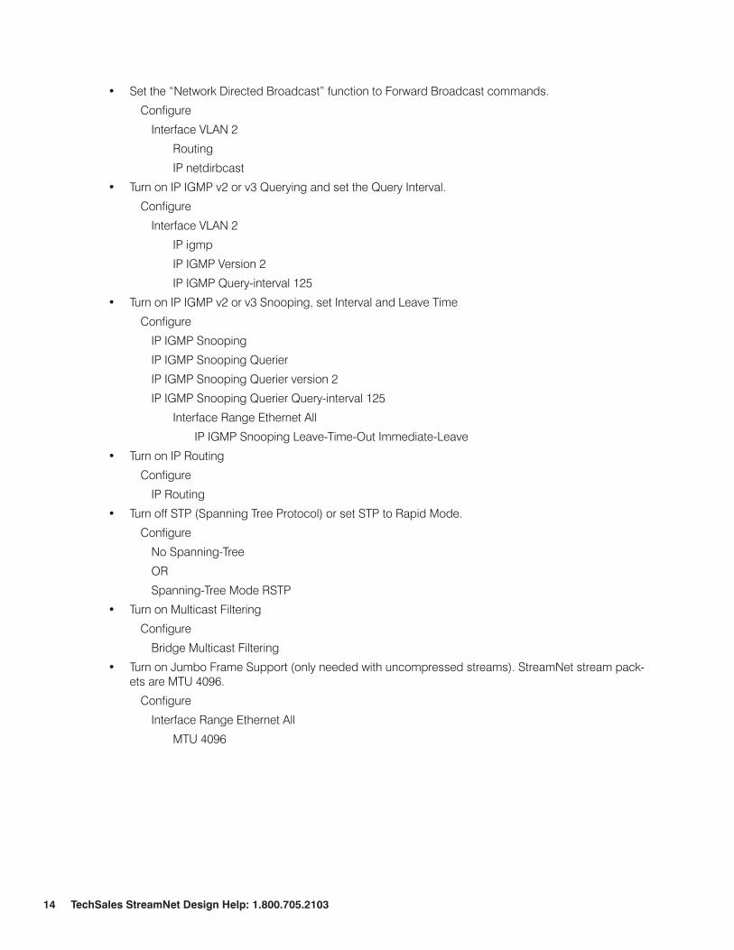
Set the “Network Directed Broadcast” function to Forward Broadcast commands.•
Configure
Interface VLAN 2
Routing
IP netdirbcast
Turn on IP IGMP v2 or v3 Querying and set the Query Interval.•
Configure
Interface VLAN 2
IP igmp
IP IGMP Version 2
IP IGMP Query-interval 125
Turn on IP IGMP v2 or v3 Snooping, set Interval and Leave Time•
Configure
IP IGMP Snooping
IP IGMP Snooping Querier
IP IGMP Snooping Querier version 2
IP IGMP Snooping Querier Query-interval 125
Interface Range Ethernet All
IP IGMP Snooping Leave-Time-Out Immediate-Leave
Turn on IP Routing•
Configure
IP Routing
Turn off STP (Spanning Tree Protocol) or set STP to Rapid Mode.•
Configure
No Spanning-Tree
OR
Spanning-Tree Mode RSTP
Turn on Multicast Filtering•
Configure
Bridge Multicast Filtering
Turn on Jumbo Frame Support (only needed with uncompressed streams). StreamNet stream pack-•ets are MTU 4096.
Configure
Interface Range Ethernet All
MTU 4096
Chapter 2: Switch configuration Settings 15
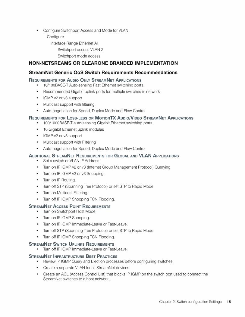
Configure Switchport Access and Mode for VLAN.•
Configure
Interface Range Ethernet All
Switchport access VLAN 2
Switchport mode access
NON-NETSREAmS OR CLEARONE BRANDED ImPLEmENTATION
StreamNet Generic QoS Switch Requirements Recommendations
requIremeNtS for audIo oNly StreamNet aPPlIcatIoNS10/100BASE-T Auto-sensing Fast Ethernet switching ports•
Recommended Gigabit uplink ports for multiple switches in network•
IGMP v2 or v3 support•
Multicast support with filtering•
Auto-negotiation for Speed, Duplex Mode and Flow Control•
requIremeNtS for loSS-leSS or motIoNtX audIo/VIdeo StreamNet aPPlIcatIoNS100/1000BASE-T auto-sensing Gigabit Ethernet switching ports•
10 Gigabit Ethernet uplink modules•
IGMP v2 or v3 support•
Multicast support with Filtering•
Auto-negotiation for Speed, Duplex Mode and Flow Control•
addItIoNal StreamNet requIremeNtS for global aNd VlaN aPPlIcatIoNSSet a switch or VLAN IP Address.•
Turn on IP IGMP v2 or v3 (Internet Group Management Protocol) Querying. •
Turn on IP IGMP v2 or v3 Snooping.•
Turn on IP Routing.•
Turn off STP (Spanning Tree Protocol) or set STP to Rapid Mode.•
Turn on Multicast Filtering.•
Turn off IP IGMP Snooping TCN Flooding.•
StreamNet acceSS PoINt requIremeNtSTurn on Switchport Host Mode.•
Turn on IP IGMP Snooping.•
Turn on IP IGMP Immediate-Leave or Fast-Leave.•
Turn off STP (Spanning Tree Protocol) or set STP to Rapid Mode.•
Turn off IP IGMP Snooping TCN Flooding.•
StreamNet SwItch uPlINkS requIremeNtSTurn off IP IGMP Immediate-Leave or Fast-Leave.•
StreamNet INfraStructure beSt PractIceSReview IP IGMP Query and Election processes before configuring switches.•
Create a separate VLAN for all StreamNet devices.•
Create an ACL (Access Control List) that blocks IP IGMP on the switch port used to connect the •StreamNet switches to a host network.