Embed Size (px)
Citation preview

Water Sensitive Urban Design
Streetscape Planning and Design Package

On the road to cleaner water | Water Sensitive Urban Design 1ii
Contents
Waterway health optimisation ...................................2
Water smart streetscapes ...........................................2
Bioretention systems ..................................................4
Swales .........................................................................6
Gully baskets ..............................................................8
Online proprietary SQIDs .........................................10
Permeable pavement ...............................................11
Technical drawings, specifications and suppliers .....13
References ................................................................13
© Brisbane City Council (2011).In consideration of Council, and the copyright owners listed throughout this document, permitting the use of this data, you acknowledge and agree that Council and the copyright owners give no warranty in relation to the data (including accuracy, reliability, completeness, currency or suitability) and accept no liability (including and without limitation, liability in negligence) for any loss, damage or costs (including consequential damage), relating to any use of this data. Data must not be used for direct marketing or be used in breach of any copyright or privacy laws.
On the road to cleaner water | Water Sensitive Urban Design

On the road to cleaner water | Water Sensitive Urban Design 1ii
On the road to cleaner waterA guide to using stormwater management measures within Council road and infrastructure projects.
On the road to cleaner water | Water Sensitive Urban Design
On the road to cleaner water | Water Sensitive Urban DesignOn the road to cleaner water | Water Sensitive Urban Design 32
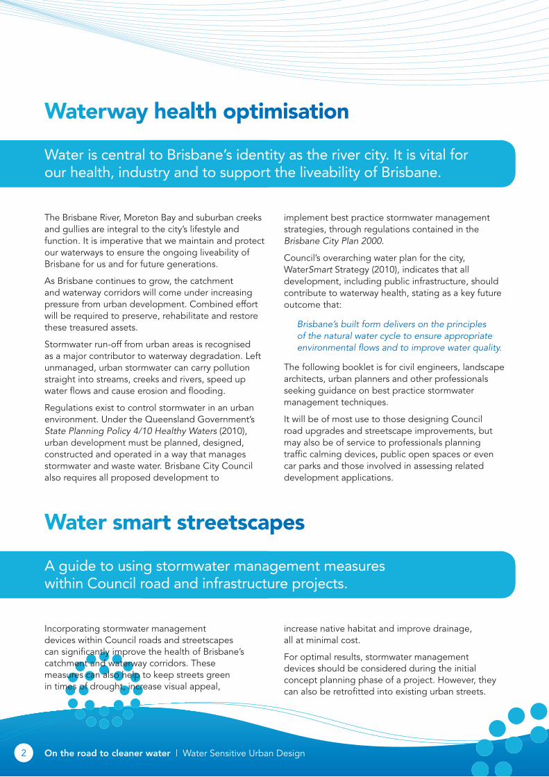
Waterway health optimisation
Water is central to Brisbane’s identity as the river city. It is vital for our health, industry and to support the liveability of Brisbane.
The Brisbane River, Moreton Bay and suburban creeks and gullies are integral to the city’s lifestyle and function. It is imperative that we maintain and protect our waterways to ensure the ongoing liveability of Brisbane for us and for future generations.
As Brisbane continues to grow, the catchment and waterway corridors will come under increasing pressure from urban development. Combined effort will be required to preserve, rehabilitate and restore these treasured assets.
Stormwater run-off from urban areas is recognised as a major contributor to waterway degradation. Left unmanaged, urban stormwater can carry pollution straight into streams, creeks and rivers, speed up water flows and cause erosion and flooding.
Regulations exist to control stormwater in an urban environment. Under the Queensland Government’s State Planning Policy 4/10 Healthy Waters (2010), urban development must be planned, designed, constructed and operated in a way that manages stormwater and waste water. Brisbane City Council also requires all proposed development to
implement best practice stormwater management strategies, through regulations contained in the Brisbane City Plan 2000.
Council’s overarching water plan for the city, WaterSmart Strategy (2010), indicates that all development, including public infrastructure, should contribute to waterway health, stating as a key future outcome that:
Brisbane’s built form delivers on the principles of the natural water cycle to ensure appropriate environmental flows and to improve water quality.
The following booklet is for civil engineers, landscape architects, urban planners and other professionals seeking guidance on best practice stormwater management techniques.
It will be of most use to those designing Council road upgrades and streetscape improvements, but may also be of service to professionals planning traffic calming devices, public open spaces or even car parks and those involved in assessing related development applications.
Water smart streetscapes
A guide to using stormwater management measures within Council road and infrastructure projects.
Incorporating stormwater management devices within Council roads and streetscapes can significantly improve the health of Brisbane’s catchment and waterway corridors. These measures can also help to keep streets green in times of drought, increase visual appeal,
increase native habitat and improve drainage, all at minimal cost.
For optimal results, stormwater management devices should be considered during the initial concept planning phase of a project. However, they can also be retrofitted into existing urban streets.

On the road to cleaner water | Water Sensitive Urban DesignOn the road to cleaner water | Water Sensitive Urban Design 32
The following pages provide information on the features, benefits and costs of five stormwater management devices:
• bioretention systems
• swales
• gully baskets
• online proprietary SQIDs
• permeable pavement.
In keeping with recent trends in water sensitive urban design (WSUD), these devices focus on treating run-off from local catchments ‘at source’, rather than offering ‘end-of-pipe’ solutions. They are designed to treat small, frequent stormwater flows prior to discharging them into underground stormwater pipe networks.
All devices are unobtrusive, maintainable, cost effective and proven by experience to be the most suitable for road projects within Brisbane.
Quick guide to selecting the best device for your location
Site features
Steep site
Shallow bed rock
Acid sulphate soils
Low permeability soils (e.g. clay)
High water table
High sediment load
Land availability
Bioretentionsystems
SwalesGully
baskets
On-line proprietary
SQIDs
Permeablepavement
Device can be used
Device may be suitable if appropriately designed
Device is generally not appropriate
Adapted from Water by Design (2009)
Summary of device benefits
Benefit
Water quality treatment
Reduced run-off frequency and volume
Bioretentionsystems
SwalesGully
baskets
On-line proprietary
SQIDs
Permeablepavement
High
Medium
Low
Negligible
Adapted from Water by Design (2009)

On the road to cleaner water | Water Sensitive Urban DesignOn the road to cleaner water | Water Sensitive Urban Design 54
Bioretention systems
Bioretention systems are soil and plant-based stormwater treatment devices consisting of vegetation, porous filter media such as sandy loam and under-drainage.
They treat stormwater by filtering run-off down through the plant, mulch and soil layer and collecting it in perforated under-drainage. As the stormwater percolates, pollutants are retained through fine filtration, adsorption and some biological uptake.
Bioretention systems often use temporary ponding to increase the volume of run-off infiltrating through the filter media.
Bioretention systems can be integrated at various scales, from tree pits to large basins. Slight reconfigurations to standard Council tree pits, tree trenches and garden beds, made at minimal cost, can turn these landscape features into excellent water cleansing devices.
Cross-section of a bioretention systemOverflow pit ‘Above design’ flows spill intro field entry pit
Extended detention Design flows temporarily pond in extended detention zone increasing volume of stormwater that is captured and treated. (this area is dry except for immediately following rainfall events)
Vegetation Functional vegetation supports nutrient removal and maintains porosity of soil
Flat Surface
Topsoil
Outlet pipe At invert of pit. Conveys treated flows and overflows to receiving waters Cleanout
Standpipe for drainage pipe cleanout
Underdrains Slotted PVC pipe at 0.5% slope
Filter cloth liner
300mm
100mm min.
Varies
100mm
200mm
Adapted from Water by Design (2009)
Base grades @ 0.5% towards pit
Drainage layer (fine aggregate)
Transition layer (coarse sand)
Filter media (sandy loam)

On the road to cleaner water | Water Sensitive Urban DesignOn the road to cleaner water | Water Sensitive Urban Design 54
Where to use themLand slope and available space should be assessed when considering a bioretention system.
Bioretention systems are best used in relatively flat areas. Steep slopes (gradients greater than four per cent) make it difficult to construct functional systems. Systems can be integrated into streetscapes at various scales but will need at least the same space required for a standard Council tree pit.
Maintenance and costsBioretention systems require similar maintenance to traditional landscaped areas. Maintenance will be highest while the plants and vegetation are
establishing within the system. Weed removal, replanting and regular watering may be required during this time (Water by Design, 2006).
Once established, bioretention vegetation should be kept healthy and the filter media permeable. Removing excessive sediment and litter and tilling the surface may be required from time to time. However, if bioretention systems are designed, constructed and established properly, they will generally continue to function effectively even if maintenance is neglected (Dalrymple, 2010).
Modifying standard Council tree pits, tree trenches and gardens to incorporate bioretention systems should result in only minor increases to construction and maintenance costs.
Approximate installation and maintenance costs
Installation cost $3000 + $500/m2 of filter area
Ongoing yearly maintenance cost $1.50 to $2/year/m2 of filter area (after vegetation is established)
Operational life 20 to 30 years
Source: Adapted from Department of Water (2007), eWater (2009), UPRCT (2004), Water by Design (2009).

On the road to cleaner water | Water Sensitive Urban DesignOn the road to cleaner water | Water Sensitive Urban Design 76
Swales
Swales are shallow channels lined with vegetation, usually grass. Swales are commonly combined with buffer strips (vegetated strips adjacent to drainage lines that stormwater sheet-flows across).
Vegetated swales are used to convey stormwater in lieu of, or together with, underground pipe drainage systems and are installed adjacent to the road pavement. They are often supported by alternative kerb design to regulate water flows.
Swales are typically aimed at slowing flows and removing sediment from stormwater.
Cross-section of a swale
Slowing flows Settling of coarse
sediment Enhanced sedimentationthrough grass
Adsorption and uptake by plants
Infiltration (varies)

On the road to cleaner water | Water Sensitive Urban DesignOn the road to cleaner water | Water Sensitive Urban Design 76
Where to use themSwales are best suited to relatively flat roads (gradients of two to four per cent) to prevent ponding, scour and erosion. The land adjacent must be open space such as a park to avoid the cost and operational problems associated with property access requirements (e.g. ‘driveway cross-overs’).
Swales typically require a minimum width of 4m. They should extend along most of the length of the road to adequately convey and treat stormwater flows.
Maintenance and costsPlants and grasses within swales should be kept healthy to ensure the swale remains vegetated. Pruning, mowing and removal of litter, debris and accumulated sediment may be periodically required. Costs for swales will vary between different local catchments.
Approximate installation and maintenance costs
Installation cost $5 to $20/m2
Ongoing yearly maintenance cost $1.50 to $2/m2/year (after vegetation is established)
Operational life 30 to 50 years
Source: Adapted from Department of Water (2007), eWater (2009), Stormwater Trust (2004), Water by Design (2009).

On the road to cleaner water | Water Sensitive Urban DesignOn the road to cleaner water | Water Sensitive Urban Design 98
Gully baskets
Gully baskets are a type of gross pollutant trap. They consist of a basket and filter bag installed within a gully pit in the kerb, rather than in a pipeline.
Pollutants are screened out of the runoff as it enters the pit. Numerous gully baskets are required within a given catchment area to provide treatment to all stormwater flows.
Gully baskets, like any gross pollutant trap, are principally aimed at removing solids conveyed by stormwater that are typically greater than 5mm. These devices commonly accumulate coarse sediment and associated pollutants.
Cross-section of a gully basket
STORMWATER LINTEL
SUSPENDED BASKET
ACCUMULATED GROSS POLLUTANTS
STORMWATER FLOW
STORMWATER PIPE
SUSPENDED BASKETSIDE HANDLES
HIGH FLOW BYPASS
VERTICALLY DISTRIBUTED PERFORATIONS
SUPPORT BAR

On the road to cleaner water | Water Sensitive Urban DesignOn the road to cleaner water | Water Sensitive Urban Design 98
Where to use themGully baskets are best suited to highly developed or impervious areas such as commercial precincts where high rates of litter and other pollutants are likely to be present within stormwater flows. Given that gully baskets are located underground within the pit, they require no space and can be easily retrofitted into space-constrained areas.
Maintenance and costsMaterial that accumulates in gully baskets must be regularly removed. Gully baskets typically require clean outs every two to six months, but this will vary based on the depth of the pit and how the surrounding land is used. If maintenance activities are not undertaken, accumulated material will eventually fill the gully basket, significantly reducing its ability to remove gross pollutants.
Costs for gully baskets will vary based on their size and the characteristics of the local catchment.
Approximate installation and maintenance costs
Installation cost $440/basket
Ongoing yearly maintenance cost $105/basket
Operational life 20 years for basket, 2 years for filter bag ($50 replacement cost)

On the road to cleaner water | Water Sensitive Urban DesignOn the road to cleaner water | Water Sensitive Urban Design 1110
Online proprietary SQIDs
The term ‘online proprietary Stormwater Quality Improvement Device (SQID)’ refers to an underground device, receiving flows from stormwater pipes, that is manufactured and supplied by a proprietary company.
As the stormwater flows into the SQID, course pollutants such as shopping bags, wrappers and cigarette butts are removed. SQIDs are designed differently but most use enhanced sedimentation baffles (e.g. through centripetal forces) and filtration to capture stormwater pollutants.
SQIDS have limited capacity to treat fine and dissolved pollutants. SQIDs that claim to remove high levels of nutrients and suspended sediments must have their performance substantiated by accredited independent testing performed under South East Queensland conditions.
Where to use themSQIDs require a large, underground space, free of services. They are typically installed downstream of a catchment greater than one hectare and upstream of a waterway or other stormwater management measure.
SQIDs are generally not recommended for low to medium-density residential areas given the relatively low litter loads of these locations and the high maintenance requirements for SQIDs.
Maintenance and costsAccumulated material generally must be removed from a SQID via a vacuum truck or excavator every three to six months. If maintenance is neglected, accumulated material will eventually fill the capacity of the SQID, significantly reducing its ability to remove pollutants. Poor maintenance can also cause reduced flow capacity, odours, remobilisation of previously trapped material and anaerobic decomposition of organics (possibly causing attached nutrients and metals to become dissolved).
When a SQID is installed it must be accompanied by a detailed maintenance plan showing how the device will be maintained to perform at optimum levels.
Capital and ongoing costs associated with online proprietary SQIDs can vary greatly, depending the type of SQID used, excavation required, the rate at which pollution is generated and other factors.
Approximate installation and maintenance costs
Installation cost $14,000 to $220,000
Ongoing yearly maintenance cost $4000 to $20,000
Operational life 50 years
Source: Adapted from eWater (2009)

On the road to cleaner water | Water Sensitive Urban DesignOn the road to cleaner water | Water Sensitive Urban Design 1110
Permeable pavement
Permeable pavement is load-bearing pavement that is permeable to water.
It has the capacity to improve stormwater quality, recharge groundwater and reduce run-off volumes, frequencies and peak rates (BMT WBM, 2009).
Permeable pavement consists of a permeable surface layer overlying an aggregate storage layer. The surface layer may be ‘monolithic’, such as porous asphalt and concrete, or ‘modular’, such as clay or concrete blocks. The storage layer consists of crushed stone or gravel which stores water before it is infiltrated to the underlying soil or discharged towards a piped drainage system (Gold Coast City Council 2007, BMT WBM 2009).
The terms ‘permeable pavement’ and ‘porous pavement’ are often used interchangeably. Permeable pavement normally refers to interlocking modular pavers and grid or lattice systems, while porous pavement is used to describe open graded aggregate material. In this document, the term ‘permeable’ is used for both.
Where to use itPermeable pavement offers an alternative to conventional impermeable pavement.
The following areas, however, are not suitable for permeable paving systems (adapted from Gold Coast City Council 2007, Coombes 2003):
• where a water table is located within 2m of the proposed pavement surface
• areas with high traffic volumes or with regular heavy vehicle traffic
• locations with saline soils, acid sulphate soils, clay soils or soils with a hydraulic conductivity of less than 0.36mm/hr
• areas where impermeable rock is located within 2m of the proposed pavement surface
• locations subject to run-off with a high sediment load.
Types of permeable pavement
Porous material
Open graded aggregate material such as asphalt and concrete with reduced or no fines and binder that allows water to infiltrate through pavement aggregate voids.
Modular pavers
Pavers made of porous material or pavers installed with gaps between them to allow infiltration to subsurface.
Grid or lattice systems
Grids, typically concrete, or those filled with soil or aggregate that water can infiltrate through to subsurface. These systems can be vegetated, usually with grass.
Source: Adapted from Gold Coast City Council (2007)

On the road to cleaner water | Water Sensitive Urban DesignOn the road to cleaner water | Water Sensitive Urban Design 1312
Locations suitable for permeable paving
Porousmaterial
Modularpavers
Grid/latticesystems
Commercial car park area 3 3
Residential or light commercial driveway 3 3
Industrial storage area or loading zone 3 3
Footpath/cycleway 3 3
Parking pad (e.g. maintenance access) 3 3 3
Tree pit surround 3 3
Source: Adapted from Gold Coast City Council (2007)
Maintenance and costsFor porous or modular pavement systems, vacuum sweeping or high-pressure hosing every three months to clear the pores in the top layer is recommended. Grid or lattice systems may also require weeding and mowing (Gold Coast City Council 2007, Water by Design 2009).
The capital and ongoing costs associated with permeable pavement can vary, depending on the type of pavement used. However, these costs are generally reported to be similar or slightly greater than conventional pavements. Increased costs are largely due to the manufacturing processes, subsurface storage requirements and extra costs associated with cleaning (Stormwater Trust 2004, Water by Design 2009).
Approximate installation and maintenance costs
Installation cost $70 to $120/m2
Ongoing yearly maintenance cost $1/m2/year
Operational life 20 years
Source: Based on Department of Water (2007), eWater (2009), Stormwater Trust (2004).

On the road to cleaner water | Water Sensitive Urban DesignOn the road to cleaner water | Water Sensitive Urban Design 1312
Technical drawings, specifications and suppliersTechnical drawings and specifications for bioretention systems, swales and permeable pavement are included on the following pages.
Gully baskets and online proprietary SQIDs are proprietary products, so standard drawings have not been included for these devices. Contact the product suppliers for copies of these standard drawings.
Reference
UMS 159
Title
Streetscape – WSUD Roadside Swale Sheet 01
UMS 159 Streetscape – WSUD Roadside Swale Sheet 02
UMS 160 WSUD Bioretention Swale Typical Details
UMS 161 Permeable Pavement Typical Details
UMS 162 Streetscape – WSUD Typical Garden Bed Type 1
UMS 163 Streetscape – WSUD Typical Garden Bed Type 2
UMS 164 Streetscape – WSUD Typical Tree Pit and Kerb Inlet
UMS 165 Streetscape – WSUD Typical Tree Trench
UMS 166 Streetscape – WSUD Typical Tree Pit and Kerb Inlet (No Tree Grate)
UMS 167 Streetscape – WSUD Typical Tree Trench and Kerb Inlet (No Tree Grate)
ReferencesBMT WBM 2009, Evaluating Water Sensitive Urban Design Options – A National Guide.
Dalrymple, BA 2010, A Review of Existing Wetlands, Bioretention Systems and Swales in South East Queensland, Stormwater Industry Association of Queensland Conference, Pelican Waters.
Department of Water 2007, Stormwater Management Manual for Western Australia.
eWater 2009, MUSIC V4 User Manual.
Institute of Public Works Engineering Australia & Water by Design 2010, Standard Drawings for Water Sensitive Urban Design.
Taylor, A 2005, Structural Stormwater Quality BMP Cost/Size Relationship Information From the Literature, CRC for Catchment Hydrology.
Upper Parramatta River Catchment Trust 2004, Draft Water Sensitive Urban Design Technical Design Guidelines for Western Sydney.
Water by Design 2006, Water Sensitive Urban Design Technical Design Guidelines.
Water by Design 2009, Concept Design Guidelines for Water Sensitive Urban Design.
Water by Design 2010a, Construction and Establishment Guidelines: Swales, Bioretention Systems and Wetlands.
Water by Design 2010b, MUSIC Modelling Guidelines for South East Queensland.
On the road to cleaner water | Water Sensitive Urban DesignOn the road to cleaner water | Water Sensitive Urban Design 1514
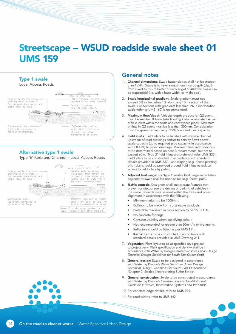
Streetscape – WSUD roadside swale sheet 01 UmS 159
General notes1. Channel dimensions: Swale batter slopes shall not be steeper
than 1V:4H. Swale is to have a maximum invert depth (depth from invert to top of batter or kerb edge) of 400mm. Swale can be trapezoidal (i.e. with a base width) or ‘V-shaped’.
2. Swale longitudinal gradient: Swale gradient must not exceed 5% or be below 1% along any 10m section of the swale. For sections with gradients less than 1%, a bioretention swale (refer to UMS 160) is recommended.
3. Maximum flow/depth: Velocity depth product for Q2 event must be less than 0.4m²/s (which will typically necessitate the use of field inlets within the swale and conveyance pipes). Maximum of flow in Q2 event must be less than 300mm. Consideration must be given to major (e.g. Q50) flows and road capacity.
4. Field inlets: Field inlets to be located within swale channel upstream of road crossings and/or to convey flows above swale capacity (up to required pipe capacity, in accordance with QUDM) to piped drainage. Maximum field inlet spacings to be determined based on note 3 requirements, but not to exceed 60m. ‘Type 2’ field inlets are preferred (refer UMS 337). Field inlets to be constructed in accordance with standard details provided in UMS 337. Landscaping (e.g. dense planting of shrubs) should be provided around field inlets to reduce access to field inlets by public.
5. Adjacent land usage: For ‘Type 1’ swales, land usage immediately adjacent to swale shall be open space (e.g. forest, park).
6. Traffic controls: Designers shall incorporate features that prevent or discourage the driving or parking of vehicles in the swale. Bollards may be used within the trees and poles alignment in accordance with the following:
• Minimum height to be 1000mm.
• Bollards to be made from sustainable products.
• Preferable maximum in cross section to be 150 x 150.
• No concrete footings.
• Consider visibility when specifying colour.
• Not recommended for greater than 50mm/hr environments.
• Reflectors should be fitted as per UMS 131.
• Kerbs: Kerbs to be constructed in accordance with standard details provided in UMS Drawing 211.
7. Vegetation: Plant layout to be as specified on a project to project basis. Plant specification and density shall be in accordance with Water by Design’s Water Sensitive Urban Design Technical Design Guidelines for South East Queensland.
8. General design: Swale to be designed in accordance with Water by Design’s Water Sensitive Urban Design Technical Design Guidelines for South East Queensland (Chapter 2: Swales (incorporating Buffer Strips).
9. General construction: Swale to be constructed in accordance with Water by Design’s Construction and Establishment Guidelines: Swales, Bioretention Systems and Wetlands.
10. For concrete edge details, refer to UMS 794.
11. For road widths, refer to UMS 142.
Type 1 swale Local Access Roads
Alternative type 1 swale Type ‘E’ Kerb and Channel – Local Access Roads

On the road to cleaner water | Water Sensitive Urban DesignOn the road to cleaner water | Water Sensitive Urban Design 1514
Streetscape – WSUD roadside swale sheet 02 UmS 159
General notes1. For general notes, refer to UMS 159-1.
2. For Type 1 Swale, refer to UMS 159-1.
3. For concrete edge details, refer to UMS 794.
4. For road widths, refer to UMS 142.
Kerb transition detail For alternative type 2 swale Section A-A
Type 2 swale Suburban routes
Alternative type 2 swale Type ‘E’ kerb and channel suburban routes

On the road to cleaner water | Water Sensitive Urban DesignOn the road to cleaner water | Water Sensitive Urban Design 1716
WSUD bioretention swale typical details UmS 160
General notes1. Bioretention filter media, transition layer and drainage layer as
per Council landscape reference specifications.
2. Under-drain, slotted rigid pipe (uPVC or similar to AS 2439.1) or approved equivalent, 0.5% minimum grade. Diameter typically 100-150mm. Pipe joins should be glued plumbing cement. Pipe should not be installed with a filter sock surrounding pipe. Under-drainage pipes shall be sealed into pits using grouts or other approved watertight seal. 50mm drainage layer (fine aggregate) cover over slotted pipe.
3. Vegetated batters are to be no steeper than 1V:4H.
4. Filter cloth – non-woven geotextile. Filter cloth not to be placed between any filter layers. Impervious liner may be required subject to soil testing requirements in accordance with the Water Sensitive Urban Design Technical Guidelines (Water by Design).
5. Traffic controls: For streetscape systems, designers shall incorporate features that prevent or discourage the driving or parking of vehicles in the Bioretention system. Bollards may be used within the trees and poles alignment in accordance with the following.
• Minimum height to be 1000mm.
• Bollards to be made from sustainable products.
• Preferable maximum in cross section to be 150 x 150.
• No concrete footings.
• Consider visibility when specifying colour.
• Not recommended for greater than 50mm/hr environments.
6. Vegetation: Refer landscape drawings for plant specification. Plant specification and density shall be in accordance with Water by Design’s Water Sensitive Urban Design Technical Design Guidelines for South East Queensland and Brisbane City Council’s ‘Subdivision and Development Guidelines’.
7. General design: Bioretention system to be designed in accordance with Water by Design’s Water Sensitive Urban Design Technical Design Guidelines for South East Queensland (Chapter 3: Bioretention Swales, or Chapter 5: Bioretention Basins).
8. General construction: Bioretention system to be constructed in accordance with Water by Design’s Construction and Establishment Guidelines: Swales, Bioretention Systems and Wetlands.
9. Services: Location of services to be verified prior to excavation. Bioretention systems must have a minimum horizontal setback of 300mm from any water supply and sewerage infrastructure.
Bioretention swale – section
Bioretention overflow pit detail – section
Bioretention under-drain cleanout

On the road to cleaner water | Water Sensitive Urban DesignOn the road to cleaner water | Water Sensitive Urban Design 1716
Permeable pavement typical details UmS 161
General notes1. Bedding aggregrate and sub-base/storage material shall
meet material and grading compatability criteria in technical specification for the works and/or the pavement manufacturer’s technical specifications.
2. The reservoir storage sub-base layer material shall comprise coarse, sound, clean stone or rock of generally uniform particle size (typically 10-63mm size) and free from silt/clay fines or other deleterious matter, or as specified in the pavement manufacture’s technical manual.
3. Filter cloth – non-woven geotextile. Filter cloth not to be placed between any filter layers. Impervious liner may be required subject to soil testing requirements in accordance with the Water Sensitive Urban Design Technical Guidelines (Water by Design).
4. Subgrade to be ripped/harrowed prior to placement of retention storage material (or, if not present, filter layer).
5. Runoff directed to porous pavements, where possible, to be pre-treated to remove coarse to medium sediments.
6. Under-drainage – slotted pipe (uPVC or similar to AS2439.1) or approved equivalent, 0.5% minimum grade, installed at 1500mm maximum centres. Diameter typically 100-500mm. Pipe joins should be glued to plumbing cement. Pipe should not be installed with a filter sock surrounding pipe. Under-drainage pipes shall be sealed into pits using grouts or other approved watertight seal. 50mm drainage layer (fine aggregate) cover over slotted pipe.
Permeable pavement typical section

On the road to cleaner water | Water Sensitive Urban DesignOn the road to cleaner water | Water Sensitive Urban Design 1918
Streetscape – WSUD typical garden bed type 1 UmS 162
General notes1. Bioretention filter media, transition layer and drainage layer
as per Council landscape reference specifications.
2. Refer to relevant section of the Water sensitive Urban Design Technical Design Guidelines (Water by Design) and project drawings for sizing of coarse sediment forebay. Refer to UMS 163 for forebay details.
3. Under-drain – slotted rigid pipe (uPVC or similar to AS 2439.1) or approved equivalent, 0.5% minimum grade. Diameter typically 100-150mm. Pipe joins should be glued plumbing cement. Pipe should not be installed with a filter sock surrounding pipe. Under-drainage pipes shall be sealed into pits using grouts or other approved watertight seal. Pipes to be installed at no greater than 1500mm from centres. 50mm drainage layer (fine aggregate) cover over slotted pipe.
4. Under-drain cleanout to be in accordance with UMS 160.
5. Filter cloth – non-woven geotextile. Filter cloth not to be placed between any filter layers. Impervious liner may be required subject to soil testing requirements in accordance with the Water Sensitive Urban Design Technical Guidelines (Water by Design).
6. Vegetation: Refer landscape drawings for plant specification. Plant specification and density shall be in accordance with Water by Design’s Water Sensitive Urban Design Technical Design Guidelines for South East Queensland. Planting density and species should be selected to discourage pedestrian access.
7. General design: Bioretention system (and associated sediment forebay) to be designed in accordance with Water by Design’s Water Sensitive Urban Design Technical Design Guidelines for South East Queensland. Planting density and species should be selected to discourage pedestrian access.
8. General construction: Bioretention system to be constructed in accordance with Water by Design’s Construction and Establishment Guidelines: Swales, Bioretention Systems and Wetlands.
WSUD garden bed – plan
Kerb transition detail WSUD garden bed – cross section

On the road to cleaner water | Water Sensitive Urban DesignOn the road to cleaner water | Water Sensitive Urban Design 1918
Streetscape – WSUD typical garden bed type 2 UmS 163
General notes1. Refer to relevant section of the Water Sensitive Urban Design
Technical Design Guidelines (Water by Design) and project drawings for sizing of coarse sediment forebay.
2. Under-drain: slotted rigid pipe to AS 2439.1 or approved equivalent, 0.5% MIN. grade. Refer project drawings for diameter and invert level (Typically Ø100-150). Pipe should not be installed with a filter sock surrounding pipe. Under-drainage pipes shall be sealed into pits using grout or other approved watertight seal.
3. Filter cloth – non-woven geotextile. Filter cloth not to be placed between any filter layers. Impervious liner may be required subject to soil testing requirements in accordance with the Water Sensitive Urban Design Technical Design Guidelines (Water by Design).
4. Refer to project drawings for vegetated batter slope (1 in 3 MAX, 1 in 4 typical) and batter topsoil requirements.
5. Construction tolerances as documented in the Water Sensitive Urban Design Construction and Establishment Guidelines – Swales, Bioretention Systems and Wetlands (Water by Design) must be achieved. Construction tolerances must be noted on project plans. Invert levels of pits, pipes and base levels must be noted on project drawings.
6. Refer landscape drawings for plant specification. Plant specification and density shall be in accordance with the Water Sensitive Urban Design Technical Design Guidelines for South-East Queensland (Water by Design).
7. All dimensions are in millimetres unless otherwise noted.
WSUD garden bed type 2 – plan Section A-A

On the road to cleaner water | Water Sensitive Urban DesignOn the road to cleaner water | Water Sensitive Urban Design 2120
Streetscape – WSUD typical tree pit and kerb inlet UmS 164
General notes1. Refer to UMS 160 for typical details of bioretention systems.
2. WSUD kerb shown is only suitable for street tree pits and small raingardens. Larger systems may need specific inlet design or mutiple inlets.
3. Where no parking lane exists, RHS kerb inlet may be replaced by an open kerb cut.
4. Where tree pit lies in a low point (sag) RHS inlets may be aligned at right angles to kerb. Ensure drainage is installed appropriately to manage stormwater volumes.
5. Ensure tree pit drainage is connected to stormwater system to avoid flooding the tree.
6. Tree pits are to be located upstream of gully pits.
7. Slotted pipe as per Council landscape specifications and in accordance with UMS 160.
8. Bioretention filter media, drainage gravel and sand layer as per Council landscape specifications and in accordance with UMS 160.
WSUD kerb inlet – cross section
WSUD kerb inlet – long section
WSUD typical tree pit – plan Section A-A

On the road to cleaner water | Water Sensitive Urban DesignOn the road to cleaner water | Water Sensitive Urban Design 2120
Streetscape – WSUD typical tree trench UmS 165
General notes1. For bioretention typical details, refer to UMS 160.
2. Refer to UMS 516 for details on soil, tree species and tree grate specifications.
3. WSUD kerb shown is only suitable for street tree pits and small raingardens. Larger systems may need specific inlet design or mutiple inlets.
4. Where no parking lane exists, RHS kerb inlet may be replaced by an open kerb cut.
5. Where tree pit lies in a low point (sag) RHS inlets may be aligned at right angles to kerb. Ensure drainage is installed appropriately to manage stormwater volumes. Refer to UMS 570 for kerb inlet details.
6. Refer to UMS detail 516 for standard tree pit notes and tree installation.
7. Ensure tree pit drainage is connected to stormwater system to avoid flooding the tree.
8. Tree pits are to be located upstream of gully pits.
9. Bioretention filter media, drainage gravel and sand layer as per Council landscape specifications and in accordance with UMS 160.
WSUD typical tree trench – plan
Section A-A Section B-B
On the road to cleaner water | Water Sensitive Urban DesignOn the road to cleaner water | Water Sensitive Urban Design 2322
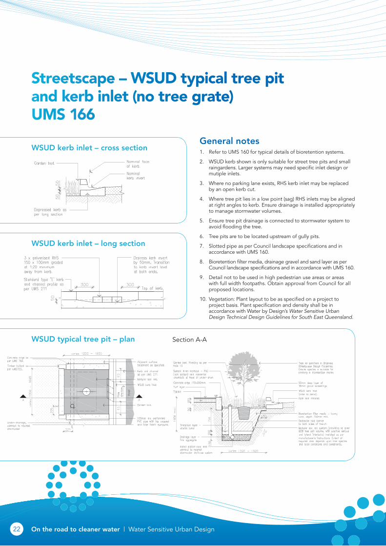
Streetscape – WSUD typical tree pit and kerb inlet (no tree grate) UmS 166
General notes1. Refer to UMS 160 for typical details of bioretention systems.
2. WSUD kerb shown is only suitable for street tree pits and small raingardens. Larger systems may need specific inlet design or mutiple inlets.
3. Where no parking lane exists, RHS kerb inlet may be replaced by an open kerb cut.
4. Where tree pit lies in a low point (sag) RHS inlets may be aligned at right angles to kerb. Ensure drainage is installed appropriately to manage stormwater volumes.
5. Ensure tree pit drainage is connected to stormwater system to avoid flooding the tree.
6. Tree pits are to be located upstream of gully pits.
7. Slotted pipe as per Council landscape specifications and in accordance with UMS 160.
8. Bioretention filter media, drainage gravel and sand layer as per Council landscape specifications and in accordance with UMS 160.
9. Detail not to be used in high pedestrian use areas or areas with full width footpaths. Obtain approval from Council for all proposed locations.
10. Vegetation: Plant layout to be as specified on a project to project basis. Plant specification and density shall be in accordance with Water by Design’s Water Sensitive Urban Design Technical Design Guidelines for South East Queensland.
Section A-A
WSUD kerb inlet – cross section
WSUD kerb inlet – long section
WSUD typical tree pit – plan

On the road to cleaner water | Water Sensitive Urban DesignOn the road to cleaner water | Water Sensitive Urban Design 2322
Streetscape – WSUD typical tree trench and kerb inlet (no tree grate) UmS 167
WSUD typical tree trench – plan
Section A-A Section B-B
General notes1. For bioretention typical details, refer to UMS 160.
2. Refer to UMS 516 for details on soil, tree species and tree grate specifications.
3. WSUD kerb shown is only suitable for street tree pits and small raingardens. Larger systems may need specific inlet design or mutiple inlets.
4. Where no parking lane exists, RHS kerb inlet may be replaced by an open kerb cut.
5. Where tree pit lies in a low point (sag) RHS inlets may be aligned at right angles to kerb. Ensure drainage is installed appropriately to manage stormwater volumes. Refer to UMS 570for Kerb Inlet details.
6. Refer to UMS detail 516 for standard tree pit notes and tree installation.
7. Ensure tree pit drainage is connected to stormwater system to avoid flooding the tree.
8. Tree pits are to be located upstream of gully pits.
9. Bioretention filter media, drainage gravel and sand layer as per Council landscape specifications and in accordance with UMS 160.
10. Detail not to be used in high pedestrian use areas or areas with full-width footpaths. Obtain approval from Council for all proposed locations.
11. Vegetation: Plant layout to be as specified on a project-to-project basis. Plant specification and density shall be in accordance with Water by Design’s Water Sensitive Urban Design Technical Design Guidelines for South East Queensland.

Brisbane City CouncilInformation
GPO Box 1434Brisbane Qld 4001
For more informationvisit www.brisbane.qld.gov.auor call (07) 3403 8888
Printed on recycled paper
N2011-02758 © Brisbane City Council 2011