Embed Size (px)
Citation preview

Strength of Materials
Prof: S .K.Bhattacharya
Dept of Civil Engineering,
IIT, Kharagpur
Lecture no 29
Stresses in Beams- IV
Welcome to the fourth lesson of the sixth module on Stresses in Beams part 4. In the last
lesson we have discussed some aspects of shearing stress in beams and we have looked into
the effect of shearing stress in a beam having a rectangular cross section. In this particular
lesson we are going to discuss what would happen if shear stress acts in a beam having cross
sections other than the rectangular one, like a circular one or the t section.
(Refer Slide Time: 01:00)
Once this particular lesson is completed one should be able to understand the concept of
shear stress in beams of different cross sections and understand the effect of shearing strain
on longitudinal strain in beams.
(Refer Slide Time: 01:28 - 02:16)

In fact we have discussed the effect of the bending movement acting in a beam and we have
calculated the stresses corresponding to that. We have also seen that the beam is subjected to
the longitudinal strain in the longitudinal direction of the beam because of the effect of this
bending. Now what is the consequence of the shearing stress which is acting in the beam on
this longitudinal strain? We will be looking into that and also one should be in a position to
evaluate shearing stresses in beam of different cross sections for different loadings.
(Refer Slide Time: 02:34 - 02:50)
Hence the scope of this particular lesson includes answering questions that were posed in the
previous lesson. We will recapitulate the aspects which we have discussed in the previous
lesson and the concept of shearing stress in beams of different cross sections is included in
this particular lesson. In this lesson we will give examples for the evaluation of shear stresses
in beams of different cross sections.
Now let us study the answers to the questions which where posed last time. The first question
given was what are the assumptions made in deriving the shear formula? In the previous
lesson we have seen how to derive the shear formula and consequently we have seen that we
have made some assumptions.
The assumptions are that at any cross section when there is shearing force acting, we assume
that the shear stress is parallel to this shear force. That means in this cross section the
direction of this shear stress is in the same direction as that of the shear force. Shear stresses
acting on a cross section are parallel to the shear force acting in that particular section.

(Refer Slide Time: 02:51 - 3:13)
Also it is assumed that shear stresses are uniformly distributed across the width of the beam
and that at any point along the depth, the distribution of the shear stress along the width is
uniform and based on this assumption. We have derived the shear formula and as we have
noticed that on a particular element, we have the vertical shear and the complimentary
horizontal shear and this is the state of stress at a particular element based on which we have
derived the shear formula. Basically these are the two main assumptions based on which we
have derived the shear formula.
(Refer Slide Time: 03:14 - 04:24)
What is the limitation of shear stress formula? While calculating the stresses in a beam due to
the shear force we have used the shear formula which is VQ/Ib and consequently we
calculate the shearing stress at any point along the depth. Now is this particular formula
applicable for all kinds of beams or are there certain limitations?

As we have seen the distribution of the shear stress across width, we are assuming that it is
uniform. Let us suppose we are dealing with a beam of rectangular cross sections. This
accuracy of this particular shear formula depends on the height to width ratio which means
that if we have a beam with a rectangular cross section having the width b and height h, the
accuracy of this particular formula depends on this ratio of h/b.
The accuracy of the shear formula increases which means that if h/b ratio is higher we get
accurate results using the shear formula or in other words for a particular depth of h, for a
constant value of h, if you have a lesser width of b, then the accuracy will be better using
shear formula. You can understand from the concept that we are assuming that the shear
stress is uniform over the width of the beam and hence if we have a smaller width, your
accuracy of the shear stress formula will be more.
But if you have a wider beam then you will be using the accuracy if you use this shear
formula. Hence this aspect should be kept in mind. This is one of the important limitations of
shear formula. Also from this it appears that for the shear formula to be more effective or to
be more applicable, the edges of the cross section must be parallel to the y axis.
Now for a rectangular or square section we have these edges which are parallel to y axis.
Now if you have a section like a triangular one or if you have a section which is semicircular,
for this kind of section, the edges are not parallel to the y axis. These sections or the shear
stress formula cannot be used for evaluating stresses for such cross sections. So this is one of
the prime limitations of the shear formula.
(Refer Slide Time: 08:24 -10:30)

Thirdly the shear formula is applicable for the prismatic beams only, which means that if a
beam has a taper and it is not uniform in each cross section then you cannot use this shear
formula for evaluating the shear stress in the beam. So these are the main limitations of shear
formula and we can use shear formula for evaluating the shear stresses in a beam when the
edges of the cross section are parallel to y axis.
For the other section like a circular one for which the edges are not parallel to y axis, we
resort to some means or the shear stresses for such sections can be evaluated by going for
other rigorous theories which we are not going to discuss at this moment. The third question
posed was; what is the value of shear stress in a cantilever beam subjected to a moment at its
tip?
You have a cantilever beam, that means the beam which is fixed at one end and if a moment
M acts at the end of this particular beam then what is the value of the shear stress in such a
beam? Let us assume that the cross section of the beam is a rectangular one. If we draw the
bending movement diagram as we have done in the past, we can remove the support and we
can write down the reactive forces and thereby evaluate these reactive forces; the vertical
force, horizontal force and the moment based on the external moment.
You will find that the vertical force will be zero, because the summation of the vertical force
is zero and there are no external vertical forces. So, the vertical reaction is going to be zero
and again the summation of the horizontal force being zero will give the value of H = 0 as
there are no horizontal forces on the beam. The moment will be the externally applied
moment and at any section we take if we draw the free body diagram corresponding to that
free body diagram, the value of the internal moment is equal to the external moment and that
is how we get the bending moment diagram which is a rectangular one which means that
everywhere we have a constant moment.
If the moment direction is reverse in a clockwise direction we will have exactly the same
result but the moment will be negative instead of positive. Since the moment is constant
everywhere you can make out the value of dM/dx which is nothing but equal to the shear
force for the constant moment dM/dx = 0. Therefore the shear force is zero and hence the
shear stress will be zero because the shear stress is VQ/Ib and since V is 0, the shear stress is
going to be zero and this answers the third question.

(Refer Slide Time: 10:31 - 14:57)
Let us see what the effect of the shearing strain on the longitudinal strain is. Let us consider a
cantilever beam whose cross section is rectangular. The shear stress in such a section varies
parabolically and since the shear stress τ varies parabolically, the shearing strain γ, which is
τ/G also varies parabolically. So, at the neutral axis we get a shearing strain and since the
stress at that neutral axis is higher, the corresponding shearing strain is also high.
If we consider a beam, a cantilever beam having a rectangular cross section and is subjected
to loads so that everywhere you have the same shear force V, then the cross section is going
to have a deformation because earlier when we have derived the bending formula we have
assumed that the plane section remains plane even after bending and it becomes
perpendicular to the axis of the beam.
Now because of this shearing strain, this distribution of the shearing strain varies and the
shearing strain is zero on the surfaces and has a maximum value at the neutral axis. The
section is going to warp in this particular form and at this point since the shearing stress is
zero and the corresponding shearing strain is zero, there will not be any deformation.
This particular line will be perpendicular to the surface and maximum deformation will occur
at the neutral axis point. For the constant shear force, all the sections are going to be in the
same form and then the strain in the longitudinal direction will have no effect because of this
shearing strain. Consequently, as we have seen, the bending formula which we have derived
from the longitudinal strain criteria will also remain unaffected.
If you have a beam where the shear force is constant and consequently the warping which we
are going to get is uniform in all cross sections, it does not have any affect as such on the

longitudinal strain and consequently we can use the bending formula even if every moment is
not uniform. It has been observed that when we go for detailed investigations for such
warping because of the non-uniform shearing stress where the shear force is not uniform
along the beam, if there is a varying shear force, then the warping will not be constant in all
cross sections and thereby there will be some amount of changes in the longitudinal strain.
But the change in the longitudinal strain is not to the extent where the accuracy level is
jeopardized and hence the bending formula can be used for beams which are subjected to
moments along with the shear. You should be in a position to appreciate that when we have
evaluated the bending formula we have considered only pure bending and consequently we
have calculated the bending stress.
When a beam is subjected to loads it is not only subjected to bending but the shear force is
also associated with that. If you have such a kind of bending, it is called non uniform bending
and when you have this bending along with shear force despite the bending formula being
evaluated exclusively for the bending moment alone, we can use the bending formula for
such beams. We also have non uniform bending where the bending is associated with the
shear force and the accuracy level is not jeopardized to a great extent and hence it is justified
to use the bending formula, even if there is warping due to the shearing stress.
If the cross section of the beam is circular instead of rectangular then what is the consequence
of this particular shear formula which we have derived earlier which is τ = VQ/Ib? Let us
consider a circular section whose radius is r and the shear force which is acting in the cross
section is in the vertical direction. As we have assumed earlier that the direction of the shear
stress also will be in the direction of shearing force and the shear stress distribution across the
width is uniform along the depth of the beam.
On the surface of this particular beam there will not be any stress and it will be zero. The
stresses which we will have are in the tangential direction and hence they are no longer going
to be parallel to the y axis. It is very difficult to use this particular formula as it cannot be
applied in evaluating the shear stresses in this particular location. At this particular point or
along this diameteral width the shearing stress is in parallel with y axis and we can compute
the shear stress only at this particular location. Now as we have seen in the case of the
rectangular one, the shear stress is maximum at the neutral axis, which is true for the circular
section as well.

(Refer Slide Time: 14:58 - 21:03)
At the neutral axis position which is along the diameter the maximum shearing stress occurs.
So, if we compute the shearing stress value at the neutral axis we will get the maximum value
of the shearing stress in the circular cross section. Along that particular diameteral width we
assume that the shear stress is uniform over the diameter and parallel to the y axis.
Hence we can use the shear formula exclusively for that particular location and we cannot use
the shear formula in the upper and the lower part using this particular expression to evaluate
the shearing stress. We can use the shear formula for evaluating the maximum value of the
shearing stress in this circular cross section. Hence,
τmax = VQ/Ib, for which Q is the section above this particular cross section where we are
evaluating the shear stress.
We take the upper half of the area for evaluating the value of Q,
Q = Aȳ = (πr2/2)(4π/3r) = 2r
2/3
Now, I = πr4/4 and b=2r, which gives,
τmax = V(2r2/3)/[( πr
4/4)(2r)] = 4V/3A = (4/3) τaverage
Hence though we cannot use the shear formula for evaluating the shear stress over the entire
cross section which is quite complex, we can evaluate the maximum shear stress at the
neutral axis position using this shear formula.

The cross section is an annular section or a tubular section where one part is open. Let us
assume that the outer radius of this is r2 and the inner radius is r1. Here moment of inertia,
I = (π/4)(r24 r1
4),
Q = (2/3)(r23 r1
3)
b = 2(r2 r1), which gives,
Let us substitute this value of I, Q and b in this expression for the maximum shear stress,
which gives,
τmax = VQ/Ib = (4V/3A)[(r22 + r1r2+ r1
2)/(r2
2+r1
2), where A = π(r2
2 r1
2)
(Refer Slide Time: 21:04 - 28:53)
Take another type of cross section where the cross section of the beam is similar to that of ‘I’.
If you remember while discussing the bending stress, we have discussed that if we take a
beam and if we have two rectangular sections placed at a distance apart, then that contributes
more to the value of the moment of inertia and thereby we get maximum effect in the bending
stresses.
Now the question was how are two rectangular strips placed apart going to be utilized as
cross sections? Subsequently we have seen that if these two particular sections are connected
by a vertical strip, then we can use that section as a beam cross section and that turns out to
be the most economical section when we talk about the transfer of the bending stress. Now if
we use those kinds of sections for a beam where they are subjected to load and thereby they

are subjected to bending moment and shearing force, then what is the consequence of
shearing stress on such sections?
The section ‘I’ is shown in the figure. It consists of two flanges, connected with a web . Now
the width of the flange is b and the thickness is h h1/2. If we are interested in evaluating the
shearing stress at any cross section which is at a distance of y1 from the neutral axis, then we
need to calculate the moment of this area which is above the section, where we are
considering the shearing stress.
Please note over here that when we have computed the shear formula we have assumed that
the shear stress is uniform across the width. In this kind of section if the width becomes larger
then the shear stress is no longer uniform over the width and if you use this formula it is
expected that the results which you are going to get will be erroneous. Since the width of the
flange is substantially large in comparison, in addition to the vertical shear which we have in
the flange we get the horizontal shear also.
Now because of this horizontal shear the shearing stress distribution in the flange part is not
uniform and consequently if we apply the shear formula for evaluating the shear stress in the
flange zone then it is going to be ineffective or erroneous. When we evaluate the shear stress
in the I cross section we are calculating the shearing stress for the web part only and in fact
you will notice that the maximum percentage of the shear force is being carried by the web
and in the process the whole section becomes effective in carrying the bending and shear.
In the case of bending we have observed that if we have two rectangular components at the
top and bottom, they are effective in carrying the bending stress. The whole section in
combination now is effective in carrying the bending and the shearing action. In the web part
which is similar to that of a rectangular section we compute the shearing stress.
We calculate the distribution of the shearing stress which is a parabolic distribution. We will
have the maximum value at neutral axis, τmax. Since we are evaluating the shear stress at this
cross section which is at a distance of y1 from the neutral axis, we take the moment of this
particular part of the area and divide it in two segments and we call them rectangle 1 and
rectangle 2.
Now for rectangle 1, A1= b( h/2 – h1/2) and A2= h1/2 – y1
Consequently, as you know Q = Aȳ

So, in the first rectangle, ȳ1 = (1/2)(h/2 h1/2) + h1/2
In second rectangle, ȳ2 = (1/2)(h1/2 y1) + y1
Now, Q = A1 ȳ1 + A2 ȳ2 = (b/8)(h2 h1
2) + (t/8)( h1
2 4y1
2)
In this particular expression note that except y12, every term is constant. Hence the shear
stress varies again with respect to y1 and in a parabolic manner. We will get the maximum
shear stress at neutral axis and the minimum shearing stress at top. At this particular section
the shearing stress is zero and at this particular section shearing stress is minimum. Hence at
this particular cross section there is a complex distribution of the shearing stress and as a
result we cannot apply the shear formula for evaluating the shearing stress in the plane zone.
(Refer Slide Time: 28:54 - 29:32)
Let us restrict ourselves to the web part and calculate the shearing stress and we will see
consequently that the maximum shearing stress is being carried by the web part only. Hence
in order to compute what is the value of the shearing force, the web is going to carry the area
of the stress diagram over the web part that is multiplied by the thickness of the web will give
us the value of the shearing force that the section will be subjected to.
Well these are the values of I of the cross section,
I = (bh3/ 2) ( t)h1
3/12 = (1/12)(bh
3 bh1
3+th1
3)
τ = VQ/Ib = (V/8It)[b(h2 h1
2)+t(h1
2 4y1
2)
This is the value of the shearing stress that we are going to get and since y1 varies we get the
variation from the bottom part to the top part.

(Refer Slide Time: 29:33 - 31:21)
Let us look at some examples I had given you in the last lesson. The beam is subjected to
loads P as shown over here where it is a two point loading and they are placed equidistant
from the two sides at the distance of 1 meter. Now you will have to determine the maximum
allowable value of P if the limiting value of bending stress is 60 MPa and the limiting value
of shearing stress is 10 MPa and the cross section of the beam is a rectangular one.
Now please note over here that you will have to find out the maximum value of P in such a
way that the bending stress does not exceed its allowable limit and consequently the shearing
stress also does not exceed the allowable limit. You will have to satisfy both the criteria and
satisfying both the criteria you have to prescribe how much load you can apply in this
particular form so that the stresses are not exceeded.
Since we are going to deal with the maximum possible value of the bending stress and the
shear stress that will be generated on this section, we need to know the variations of the
bending moment and the shear force along the length of the beam. Thereby we need to
compute the bending moment and shear force diagram so that we can find out the value of the
maximum bending moment and the maximum shear force that is occurring at any point in the
beam. Consequently we can also compute the value of the stresses.
(Refer Slide Time: 29:33 - 31:21)

Let us look at some examples I had given you in the last lesson. The beam is subjected to
loads P as shown over here where it is a two point loading and they are placed equidistant
from the two sides at the distance of 1 meter. Now you will have to determine the maximum
allowable value of P if the limiting value of bending stress is 60 MPa and the limiting value
of shearing stress is 10 MPa and the cross section of the beam is a rectangular one.
Now please note over here that you will have to find out the maximum value of P in such a
way that the bending stress does not exceed its allowable limit and consequently the shearing
stress also does not exceed the allowable limit. You will have to satisfy both the criteria and
satisfying both the criteria you have to prescribe how much load you can apply in this
particular form so that the stresses are not exceeded.
Since we are going to deal with the maximum possible value of the bending stress and the
shear stress that will be generated on this section, we need to know the variations of the
bending moment and the shear force along the length of the beam. Thereby we need to
compute the bending moment and shear force diagram so that we can find out the value of the
maximum bending moment and the maximum shear force that is occurring at any point in the
beam. Consequently we can also compute the value of the stresses.
Let us compute the bending moment and shear force diagram. The first step is to evaluate the
unknown reactive forces. Let us call this beam as A and B and end A is on hinge so you have
a vertical force RA and a horizontal force HA and the vertical force at B as RB as the reactive
forces. The summation of horizontal forces = 0 will give you HA = 0 and you can compute
the value of RA and RB.

(Refer Slide Time: 31:22 - 36:29)
Since this is a symmetrical beam with symmetrical loading RA = RB = P. We can compute the
value of shearing forces at any cross section and we can draw the shear force diagram over
the left region between the support and the load. We will have a shear force of longitude P
kN which is negative and between the second load point and last reaction we have again P kN
which is positive. The maximum value of the shear force occurring anywhere in the beam is
P kN and in between the loads there are no shear forces at all. So, the maximum shear force is
= P kN.
The maximum value of the bending moment that you get is P kNm and that is occurring at a
load point and maximum shear force is occurring within the support and the load point.
Bending stress, σ = My/I
Now, for rectangular section, I/y = bh2/6
As the bending stress is limited to 60 MPa, substituting all the values in bending stress
equation, we get,
60 = (P⨯106⨯6)/(100⨯250
2), which gives, P = 62.5 kN.
From the maximum bending stress criteria we get the value of P = 62.52 kN.
Now let us look into the value of P which we get if we have to satisfy maximum shearing
stress criteria. Now as we know that the maximum shear stress in a rectangular cross section
occurs again at the neutral axis since it varies parabolically and the maximum value which we
get is,
τmax = 3V/2A
Now maximum shear stress is = 10 MPa, Vmax = P and cross sectional area is 100*250.
Substituting all the values, we get, P = 166.7 kN.
So now that you have two values of P and you have to choose the most appropriate one, now
if you use the higher value of these two, P = 166.7N, if we use that value then the bending
stress is going to be go beyond the 60 MPa. That is the limiting value because we have
obtain the value of p corresponding to the bending stress as = 62.5 kN and if we use 62.5 kN
as the loading then shearing stress will be lower than 10 MPa.
Since we cannot go beyond the allowable limit of the stresses we have to use the lower value
of the beam so that both the stress criteria, bending stress and the shearing stress are satisfied
and the member is safe against this loading. The value of the P which should be used is 62.5
kN. Now let us look into another example problem in which there is an application of the
shearing stress. Now the maximum vertical shear force acting on this beam cross section is
given as 100kN.
(Refer Slide Time: 36:30 - 37:55)
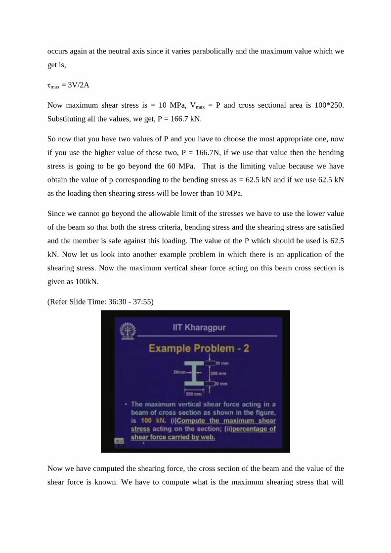
Now we have computed the shearing force, the cross section of the beam and the value of the
shear force is known. We have to compute what is the maximum shearing stress that will

occur in this particular section and how much shear force is going to be carried by the web
out of the total shear force in this particular cross section.
You have to compute the maximum shear stress acting on this particular section and then
percentage of shear force that will be carried by the web of the beam. Now the cross section
of this is an ‘I’ section; this is a symmetrical one so the position of the neutral axis will divide
the section into two equal halves. This is the position of the neutral axis and we have to
compute the maximum value of the shear stress which will be acting at the neutral axis
location.
(Refer Slide Time: 37:56 - 45:40)
Let us compute the value of Q for evaluating the shearing stress. For computation of
maximum shear stress,
Q = Aȳ = 200⨯20⨯110 + 100⨯20⨯50 = 54⨯104
mm3
Similarly, for computation of minimum shear stress,
Q = Aȳ = 200⨯20⨯110 = 44⨯104
mm3
As we know, shearing stress, τ = VQ/I
Now, I = (200⨯2403/12) ( ⨯200
3/12) = 110⨯10
6 mm
4
Thus, τmax = (100⨯103⨯54⨯10
4)/( 110⨯10
6⨯20) = 24.5 MPa
τmin = (100⨯103⨯44⨯10
4)/( 110⨯10
6⨯20) = 19.93 MPa

We compute the maximum stress and the minimum stress and this is the maximum value of
the shearing stress that will be occurring in the beam section when they are subjected to the
shear force of 100 kN and the maximum value of the shear stress is at the neutral axis and the
magnitude of that is 24.5 MPa.
Let us look into the second aspect of it in which we need to find out the shear force out of
100 kN the web part of is going to carry. Since we know is stress times area, so if we take the
area of this shear stress distribution multiplied by the thickness, it will give us the shear force
that will be carried by web. The shear force which is being carried by web is equal to the
thickness of the web multiplied by the area of the stress diagram.
S.F. = t⨯Adiagram
We can divide this area of the stress diagram into two parts; one is the rectangular part and
another one is this parabolic distribution.
Thus, S.F. = 20⨯[200⨯19.93+ (2/3)⨯200⨯4.57] = 92 kN
Please note over here that out of the 100kN shear force that the entire cross section is
subjected 92 kN shear force is being carried by the web alone. Hence the 92% of the stress
total shearing force is being carried by the web.
We have called the top and the bottom rectangle flanges. This flange is effective in carrying
the bending stress whereas the web is quite effective in carrying the shearing stress because
92% of the shear force is being carried by this particular web. Hence in fact in normal design
or in an engineering design where we do not really need to compute the stresses, we assume
that the shearing stress is being carried by the web alone and the bending stresses are being
carried by the flanges of this section and that simplifies the calculation to a large extent.
Now let us look into another example where we have a beam and is loaded such that the loads
are P at the two ends and 4P at the center. Now let us call different pomits as A, B, C D and E
as shown in the figure. So it is hinged at B, roller support at D and overhang at A and E. the
cross sectional area is similar to that of T section. Also we have discussed as in the case of
the ‘I’ section that we cannot use a shear formula for evaluating the shear stress in the flanges
of the ‘I’ beam. For T section also, if we compute the same shearing stress in flange using the
shear formula it is not going to be accurate or correct. Hence we restrict ourselves to the
evaluation of shear stress only in the web part of the beam.

(Refer Slide Time: 45:41 - 48:05)
Here the neutral axis position is given which is at a distance of 70 mm from the top of the
beam and the moment of inertia of this particular cross section also is given. We would like
to know the maximum shear force value of P, so that the shearing stress does not exceed
beyond this allowable stress limit of 6 MPa, but it is silent about the maximum allowable
bending stress.
Since it is not indicated with regard to the bending stress we compare our actual shearing
stress that is going to happen in the beam because of such loading and if we equate it to the
maximum allowable shearing stress then we can find out what is the value of P that we need
so that the shearing stress does not go beyond the 6 MPa value.
(Refer Slide Time: 48:06 - 50:36)
Let us look into the shear force diagram of this particular beam and as usual. Let us compute
the value of the reactive forces RB and RC. The maximum value of the shear force is 2P. This

is the maximum value of the shearing force which is indicated in shear force diagram and the
value of the moment of inertia is already given. In the case of a rectangular section we get a
maximum amount of shear stress at the neutral axis. For this rectangular component now at
this particular section our shearing stress is not zero, but you will have some value which is
called as τmin, because we have some area for which we get the Q value which is Aȳ. Above
the web, we have the flange area which is contributes to the first moment of area Q but we
are calculating the shearing stress from the interface and downward, so we have some value
of the shear stress at the interface between the web and the flange and we are calling that the
minimum shearing stress which is τmin.
If you compute the value of this maximum shearing stress at the neutral axis,
τmax = VQ/It
Here, Q = 80⨯20⨯60 + 50⨯20⨯25 = 121⨯103 mm
3
If we substitute these values, we get,
6 = (2P⨯103⨯121⨯10
3)/(15.52⨯10
6⨯20), which gives, P = 77 kN
So the maximum value of P which can be applied in this beam is 77 kN, so that the shearing
stress does not exceed a value of 6 MPa as stipulated over here.
(Refer Slide Time: 50:37 - 51:31)
Let us look into this particular problem which has relevance with the discussion we had today
and it is that the cross section of this particular pole is a wooden pole having a solid circular
section of diameter d and this is subjected to a lateral load of 2.5 kN at the top. Now as you
can make out, this particular member is subjected to this load and you can orient this and take
this as a cantilever beam subjected to a load at its tip which is of value 2.5 kN and this length

is equal to 2 meters. We have to determine the diameter of this particular pole so that the
stress in bending does not exceed 20 MPa and the stress in shear does not exceed 5MPa.
(Refer Slide Time: 51:32 - 53:37)
If we draw the bending moment and shear force diagram for this particular pole then the
bending moment and shear force diagram is going to be as shown in the figure, which we
have already done earlier.
Vmax = 2.5 kN and Mmax = 5 kNm
Now if we compute the bending stress from this particular expression which is, σ = My/I
Now, for the given section, I/y = (πd4/64)/(d/2) = πd
3/32
Thus, 20 = (5⨯106⨯32)/(πd
3), which gives, d = 136.6 mm
Corresponding to the maximum shear force of 2.5 kN. We need to evaluate the maximum
shearing stress as we cannot compute the shearing stress at any other point in this particular
circular cross section.
So, τmax = 4V/3A, which gives,
5 = (4⨯2.5⨯103⨯4)/(3⨯π⨯d
2), which gives, d = 29.14 mm
Now out of these two values where corresponding to bending, we have d as 136.6 mm
corresponding to shear, we have 29.14 mm. Naturally we will have to go for the larger
diameter so that it can withstand both the stresses and when we provide the lower diameter it
will be safe but not against bending. However if you go for the larger diameter then it will
satisfy both the criteria hence the diameter of the pole has to be minimum as 136.6 mm so
that it can withstand both the stress or withstand this amount of load, so that the bending
stress and shear stress are within limits.
(Refer Slide Time: 53:38 - 54:40)
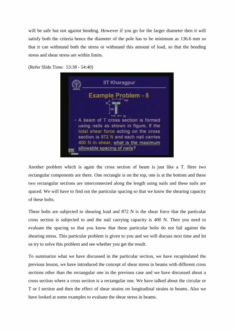
Another problem which is again the cross section of beam is just like a T. Here two
rectangular components are there. One rectangle is on the top, one is at the bottom and these
two rectangular sections are interconnected along the length using nails and these nails are
spaced. We will have to find out the particular spacing so that we know the shearing capacity
of these bolts.
These bolts are subjected to shearing load and 872 N is the shear force that the particular
cross section is subjected to and the nail carrying capacity is 400 N. Then you need to
evaluate the spacing so that you know that these particular bolts do not fail against the
shearing stress. This particular problem is given to you and we will discuss next time and let
us try to solve this problem and see whether you get the result.
To summarize what we have discussed in the particular section, we have recapitulated the
previous lesson, we have introduced the concept of shear stress in beams with different cross
sections other than the rectangular one in the previous case and we have discussed about a
cross section where a cross section is a rectangular one. We have talked about the circular or
T or I section and then the effect of shear strains on longitudinal strains in beams. Also we
have looked at some examples to evaluate the shear stress in beams.

(Refer Slide Time: 54:43 - 55:14)
In this module of stresses in beams which consists of four lessons we have divided it into two
parts. The first two lessons are focused on the aspects of bending stresses, the last two
lessons were focused on the aspects of shearing stresses and thereby we have seen the effects
of loads in terms of bending and shearing stresses in beams.
(Refer Slide Time: 55:15 - 55:41)

(Refer Slide Time: 55:42 - 56:01)
The questions that I have set for you are that in a beam with a rectangular cross section, what
is the maximum value of shear stress and where does it occur? In a beam with a circular cross
section what is the maximum value of shear stress and what is meant by average shear stress?
While we were discussing, we had looked into a term called average shear stress but what do
we really mean by average stress? Look into these questions and try to find answers for them.
We will discuss these questions in the next lesson.