Embed Size (px)
Citation preview

Strength of Materials Prof: S.K.Bhattacharya
Department of Civil Engineering Indian institute of Technology
Kharagpur Lecture no 22
Lecture Title: Bending of Beams- I
Welcome to the first lesson of module 5 which is on Bending of Beams part 1. In fact the last four modules which we have looked into were on the effect of axial force on bars and correspondingly we have looked into the aspects of stresses and strengths. Subsequently, we have looked into the effect of the twisting moment on bar. In this particular lesson, we are going to study some other aspects of loading on this kind of system. (Refer Slide Time: 00:45 - 01:17)

(Refer Slide Time: 01:18 - 01:58)
So long we were talking about the forces in a bar. Now we have brought in a specific term which is called beam. We will look into what is meant by that and the different forces which act on beam. Then one should be able to understand different types of supports and types of beams. One should be able to understand the concept of shear force and bending moment and be in a position to evaluate reactive forces for different kinds of loading on different types of beams. (Refer Slide Time: 01:59 - 02:48)
In this lesson we will look into what a beam means and what the different types of supports are on which a beam member is supported and the different types of loading that the member will be subjected to. The scope of this lesson includes the evaluation of reactive forces in different types of beams, the concept of shear force and bending moment in beams and the examples for the evaluation of reactive forces for different beams under different loading conditions. We will evaluate the reactive forces in beam members and consequently we will look into how to evaluate the shear force and the bending moment. (Refer Slide Time: 02:49 - 03:33)
Before we go to the bending of beams or bars let us first examine the aspects of the answers to the questions which were given last time. The questions which were set were related to the torsional aspects. The first question posed was: how is the strength to weight ratio of a bar subjected to torsion defined. We did an example wherein we had evaluated the strength to weight ratio. Basically by the phrase ‘the strength of a bar against twisting motion’, we mean the strength of the bar to resist the twisting moment. The carrying capacity of the bar of the twisting moment is basically its strength, and the weight of a bar is its cross sectional area multiplied by length and unit weight of the material. The ratio of these two parameters will give us the strength to weight ratio.

(Refer Slide Time: 03:34 - 05:04)
The strength to weight ratio of a bar is defined as the capacity of carrying twisting moment to the weight of the bar. If twisting moment is defined as T or designated as T and weight is designated as W then the ratio of the strength to weight is T/W, where W is the weight given by the cross sectional area multiplied by length multiplied by the unit weight. T divided by this ratio gives us the strength to weight ratio. A is the cross sectional area, L is the length of the member and Gamma is the unit weight of the material. This is what we defined as the strength to weight ratio. (Refer Slide Time: 05:05 - 06:50)
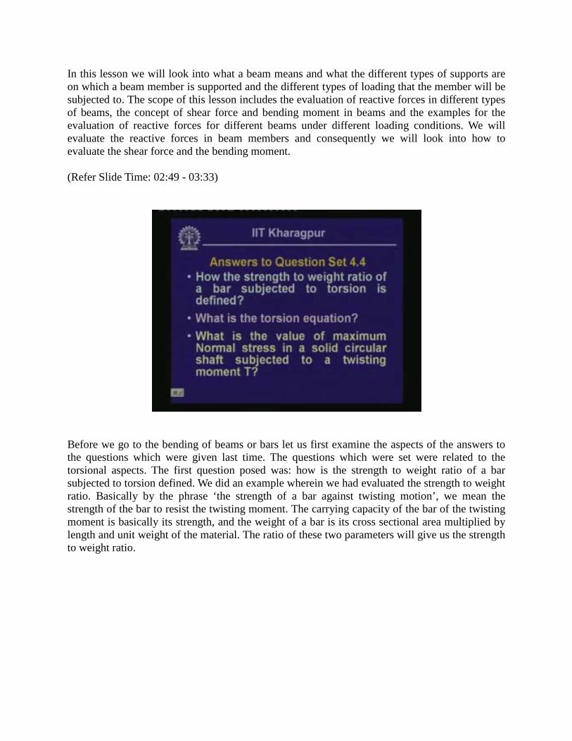
The second question is: what is torsion equation? After going through the module on torsion you know that the torsion equation is defined by this expression where this is given as T/J = Tao/rho = G theta/L. Now T here is the twisting moment or the torsional moment which acts on the shaft. J is the polar moment of inertia and for the solid section the polar moment of inertia is pi d to the power of 4 by 32 where d is the diameter of the bar and for tubular section this becomes pi by 32 times do to the power of 4 – di to the power of 4. For solid section this is the polar moment of inertia and for tubular section this is the polar moment of inertia. Tao is the shear stress; rho is the radius at the point where we are trying to define the shear stress, G is called the shear modulus and theta is the rotation of the bar and L is the length. So, these are the terms and this is defined as the torsion equation which is T/J= tao/rho = G theta/L and we are aware that all the terms have their usual meanings. The third question is: what is the value of maximum normal stress in a solid circular shaft that is subjected to a twisting moment?
(Refer Slide Time: 06:51 - 09:52)
We have also discussed this through a problem. Let us examine it once again. This particular bar is fixed at this end subjected to a twisting moment T. T is a positive moment, as we have defined that the twisting moment acts in the bar in such a way that the thumb projects towards the positive x direction which is the positive twisting moment. So, when it is subjected to the positive twisting moment and if we look into a small element this particular element is subjected to shearing stress which is of this form. What happens when we try to plot this shearing stress of this element in terms of Mohr circle? Sigma x is of the Mohr circle; this is the shearing stress axis of the Mohr circle and these are the positive directions for Tao and Sigma. Here the shearing stress acting on this particular element

according to our convention is negative, as this particular shear along with this complimentary shear makes a moment in the clock vise direction which is negative. So, on this particular axis it represents this particular point whereas the shear on the other plane is positive which makes a clock wise moment. This is represented by this particular point.
Now if we plot the circle then this is the Mohr circle of the stress and this particular point which is on the Mohr circle represents the plane where we have the maximum normal stress. We call this as Sigma1 and incidentally the value of it is equal to Tao. This is Tao; this is also Tao which is the radius of the circle and since normal stress is 0 on this which is a state of pear shear the normal stress is equal to Tao. This particular point is at an angle of 90 degrees with reference to the reference plane. In the physical plane (since it is Mohr’s plane 2 Theta is 90 degrees, Theta is 45 degrees) if we move clockwise by 45 degrees which is shown here. Perpendicular to this the plane which you get is the plane along which it will fail and the direction of the normal stress Sigma1 is this. This is the normal stress Sigma1 and consequently the other normal stress which is the minimum value will be Sigma2 which is equal to Tao.
These are the values of the normal stresses which get generated because of the action of the twisting moment acting in a bar. So long we have discussed the forces that act in a bar in the direction of its long axis and we have called the load which acts as the axial load or axial force. At any cross section if we try to find out the stress corresponding to that, we have looked into this normal stress as equal to the load divided by the area. We have also subsequently seen that when a bar is subjected to a twisting moment, the vectorial notation of this particular twisting moment is in the direction of the axis which is the long axis of the bar.
We are going to discuss the loading in a bar where the vectorial directions of this loading, either the direct load or the moment is perpendicular to the axis of the bar and these particular kinds of loads are transverse to the bar and we call those kinds of members which are subjected to these transverse loads as beams. In the case of bars, the loads were axial and their vectorial direction is along the axis of the bar whereas for the members which we are terming as beam, the loads are transverse to the member and the vectorial direction of these forces, either the load directly or the vectorial direction of the moment, are perpendicular to the axis of the bar.

(Refer Slide Time: 09:54 - 14:53)
If we have a bar in which the rhos act transverse to its direction, the vectorial direction is perpendicular to the axis of the bar. Also we may have a moment which acts in the beam. If we look into this particular moment in this beam, you have a moment in this plane; so its vectorial direction is perpendicular to the axis of the beam. The loading of x on a bar is what we designate as beam. Members which are subjected to loads that are transverse to the longitudinal axis are termed as the beam and the members are either subjected to the forces or the moment having their vectors perpendicular to the axis of the bar.
All these forces that act in the beam member which are transverse to this particular member, act in the same plane. This is the plane of the beam and the forces which are acting on it along with the moment are in the same plane and that is why we term these kinds of structures as the planar structures. In the same plane, we have the bar and the loading and consequently we will see that when this bar or the beam is subjected to this transverse load it will undergo deformation and this deformation also will be in this particular plane. When the forces acting on this beam along with the plane of the beam and its deformation are in the same plane, we call them as a planar structure.
We already know that the moment about an axis is perpendicular to the cross section. Now we are going to talk about the moments about the axis which are in the plane of the cross section. If the cross section is a rectangular one then the axis which lies in this particular plane, the bending of the moment, will act about this axis. When this moment acts about the axis it lies in the plane of the beam itself.
If we look into both the moments the vectorial direction of both the moments is perpendicular to the long axis of the beam. When we are dealing with the bending moments which are in the plane of the beam along with the forces we call that plane as the plane of bending and because of this

particular moment, we call the beam member or the member which is subjected to the transverse loading undergoing a bending, as the bending moments. Before we really go to the details of beams let us look into some kind of supporting arrangement on which a bar is supported. We call one of the supports as pinned support or hinged support.
(Refer Slide Time: 14:54 - 15:09)
(Refer Slide Time: 15:10 - 19:54)

Here you see diagrammatically we have shown some figures. This part is supported by a joint in which this particular end of the beam cannot undergo displacement in the horizontal direction; it cannot undergo displacement in the vertical direction, but this beam allows the bar to move in this form. That means it can undergo a rotation. It cannot move horizontally, it cannot move vertically but it can rotate. The rotation of this particular end of the bar is allowed and it can have some amount of rotation which you may designate as Theta.
Generally when we study problems we designate them in such a way that in this particular form, this particular type of support indicates that it is either a hinged support or pinned support. We have a support of this particular form wherein it is rests on to rollers. When this part of the segment is loaded then this particular support can move. This can move in the horizontal direction since it is supported on the roller. Hence horizontal movement is possible but the movement in the vertical direction is restricted. Also it can have rotation as we had in the previous case for a hinged support. We call this kind of support, a roller support.
Take these two kinds of supports; the hinged support and the roller support. In the case of hinged support the movement of this particular end both in the horizontal direction and the vertical direction is restricted. Since they are restricted it is expected that some amount of reactive forces will be generated and these reactive forces will be in the vertical direction and in the horizontal direction. In the case of a roller support since restriction of movement is only in the vertical direction and it is free to move in the horizontal direction, there will be a vertical reactive force which is perpendicular to this roller plane. We call this kind of support, a fixed support.
This particular end of the beam is fixed at this point. The meaning of this fixity is that this particular point cannot have any displacement in the horizontal direction and cannot have any displacement in the vertical direction. This part is not allowed to rotate freely. If we look into this particular axis it will remain straight over here. No rotation as we had in the previous cases is allowed in this case.
Here the horizontal moment, the vertical moment and the rotational moment are restricted. When these three motions are restricted, naturally corresponding to all these three motions we will have the reactive forces. Since the vertical motion is constrained there will be a vertical reaction and since the horizontal moment is constrained there will be a horizontal reaction. Since it is not allowed to rotate it has to be held back.
A hinged support has two reactive forces; one vertical and one horizontal because it is not allowed to move in these two directions. In the case of a roller support since it is allowed to move in one horizontal direction there will be only a vertical support or vertical reactive force and for a fixed support we will have three reactive forces. They are the vertical reactive force, the horizontal reactive force and a moment at that particular point. These are the different kinds of supporting arrangements that we have. The supports which have been shown over here are the pinned support or hinged support, the roller support and the fixed support.
Based on these kinds of supports we classify the beams as well. A member or a beam member is supported at its two ends. Let us say on one end it is supported by a hinged connection and on the other end it is supported by a roller connection. When they are subjected to the transverse
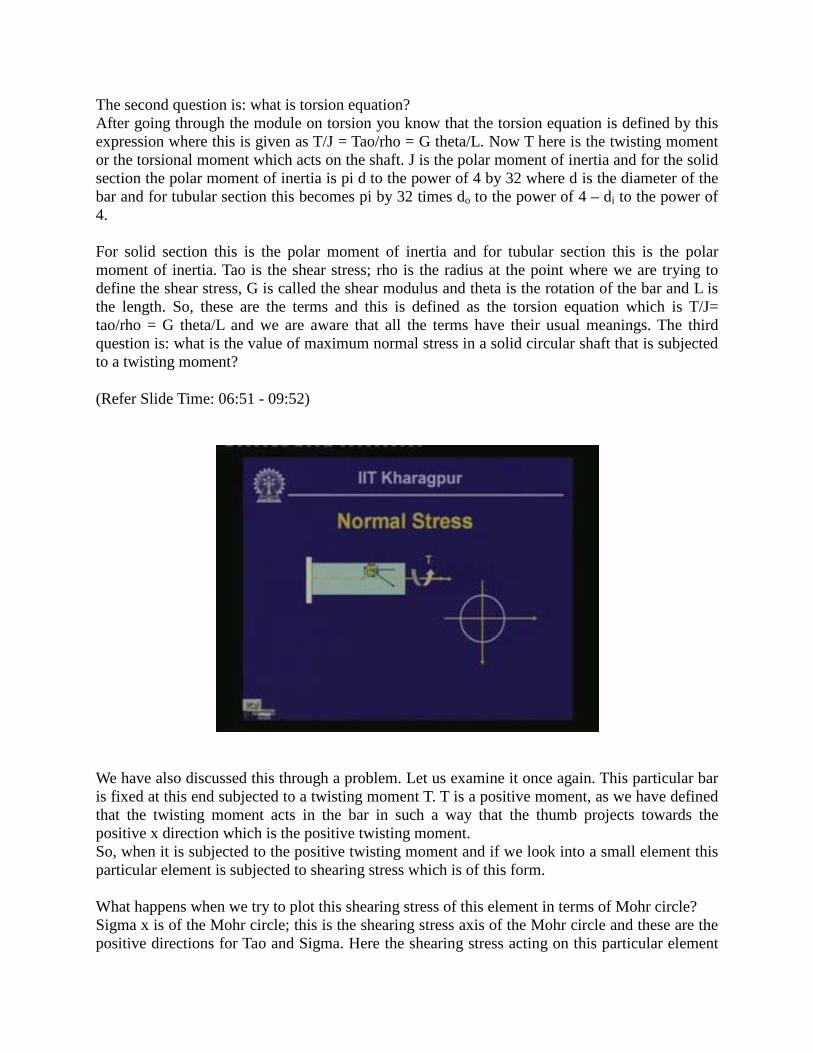
loads it resists them by generating the reactive forces in the supports. The reactive forces generated in these supports will be of this particular form and we call this kind of beam, a simply supported beam. So, when we talk about a simply supported beam it means that one end of it is hinged and the other end is on the roller.
(Refer Slide Time: 19:55 - 24:29)
Notice that we have two unknown reactive forces on this particular end A. On this particular end B we have one reactive force. There are three unknown reactive forces and as we know that in the equations of static equilibrium we have three equations, we can solve these three unknown reactive forces using three equilibrium equations. These kinds of members are called statically determinate because the three unknown reactive forces can be readily determined using the three equations of statics. We encounter another kind of beam called cantilever beam where the beam member is fixed at one end and free at the other.
At this fixed support it is expected that there will be three reactive forces generated; one is the vertical force, one is the horizontal force and another one is the moment. These three reactive forces will be generated at this support and again if we look into this particular member since we have three reactive forces they can be evaluated using equations of statics and hence this member is also a statically determinate member.
Sometimes we use a beam member which may not be in any of these categories but could be a combination of them. For example, we have a beam which is hinged at this place and placed on a roller at this particular place and subjected to some kind of loading on the transverse plane. This part of the beam is extended beyond the support point. This part is generally called the overhang part of the beam. This is a simply supported beam with an overhang.

This part is like a cantilever beam but in this cantilever beam the rotation is allowed because it is supported at this point and has a vertical constraint. But then because of this overhang it is expected that it can generate moment and it can also generate rotation. But being a roller support it cannot resist any rotational aspect over there and there is expected to be a rotation. We generally call these kinds of beam members as beams with overhang. So, the different kinds of designations are simply supported beams, cantilever beams or beams with overhang.
Henceforth whenever we mean that a simply supported beam is loaded with transverse load, it means that the beam is supported on a hinged support at one end and the roller support at the other or if we say that the cantilever beam is loaded with such and such loading, it means that the one end of the beam is on a fixed support and the other end is free and when there is a fixed support, it is expected that there will be three unknown reactive forces which have to be evaluated using equations of statics.
(Refer Slide Time: 24:30 - 30:10)
Having looked into the types of supports and the types of beams we designated, let us look into the different types of loads that a beam member encounters. Let us suppose we have a simply supported beam which is hinged at one end and supported on roller at the other. Then we have designated one load which is known as concentrated load. The meaning of this is that if a load which acts on an infinitesimally small area is distributed in that particular small area then we call that force or load as a concentrated load.

(Refer Slide Time: 25:40)
Many times the hole of the beam may be subjected to a load which is distributed over the entire length. (Refer Slide Time: 25:40) This is the length of the beam and the entire length of the beam is subjected to a load which is uniform and the intensity of this load could be say q bar unit length. Now this load is called a uniformly distributed load as it is distributed over the entire span having uniform intensity. So, we call such a loading system a uniformly distributed load, or in short many times it is referred to as udl. When the simply supported beam is subjected to udl, it indicates that a beam, which is hinged at one end and roller supported at the other, is subjected to a uniformly distributed load over the entire span of the beam or the length of the beam.
There is another kind of loading called linearly varying loading. We may have a beam member or a simply supported beam which is hinged at one end and roller supported at the other and this has a load which varies in this rectangular pattern. Here the intensity is 0 and here say maximum intensity is q; this span of the beam or the length of the beam in its entire length is subjected to a load which is linearly varying.
It can be of different types. It could be in the form that we have indicated or we could have a loading and a member that vary in a trapezoidal form. There could be different kinds of variations. Here we have intensity q1, we have intensity q2 and between these two it varies in this form. It is a trapezoidal variation but between these two points q1 is constant over here and from one point to another it varies linearly. Everywhere the intensity of the loading varies in a linear form.
Other then this distributed loading or concentrated loading we get loading in the form of a concentrated moment. Let us say that we have a beam and let us say this is a cantilever beam which is fixed at this end. At a particular point in the beam it is subjected to a moment M at this
point. This will have effects or there will be reactive forces generated because of the application of this moment and we call this kind of loading as concentrated moment.
In general a beam member supported on certain kinds of support (as we have seen the different kinds of supports) can be subjected to different kinds of loading. They could be concentrated load, the linearly varying load, uniformly distributed load or concentrated moment either individually or a combination of these different kinds of loads. When this member is subjected to all these transverse loading in the plain of the member we call it a beam member.
Finally, our objective is to evaluate the stresses in this member but before we really go into the evaluation of stresses we will have to examine how internal forces are generated in this member because of the transverse loading. In the previous modules we have seen that when a bar element is subjected to the axial pull how the stresses get generated within the internal part of the body or because of the twisting moment how the stresses get generated in the bar. We will now look into how the internal forces or internal stresses get generated when a beam element is subjected to this transverse loading.
(Refer Slide Time: 30:11 - 33:40)
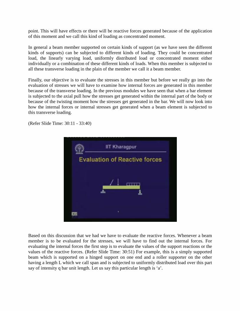
Based on this discussion that we had we have to evaluate the reactive forces. Whenever a beam member is to be evaluated for the stresses, we will have to find out the internal forces. For evaluating the internal forces the first step is to evaluate the values of the support reactions or the values of the reactive forces. (Refer Slide Time: 30:51) For example, this is a simply supported beam which is supported on a hinged support on one end and a roller supporter on the other having a length L which we call span and is subjected to uniformly distributed load over this part say of intensity q bar unit length. Let us say this particular length is ‘a’.

(Refer Slide Time: 30:51)
Vertical concentrated load acts at a distance of b from here. Let us say an inclined load at an angle of Theta acts at a distance of c from here and this gap could be d. Let us draw the free body diagram that means removing these supports and drawing the corresponding reactive forces. We will then have one vertical reactive force and one horizontal reactive force for the hinged support. If we call this end as A, this end as B then let us call this as RA, this as HA and this end will have a vertical force only, as a horizontal moment is allowed and we will have this as RB.
So, the three reactive forces RA HA and RB have to be evaluated from the equations of statics. We have three equations of statics where the summation of vertical forces is 0, summation of horizontal forces in the beam is 0 and summation of moment at any point is equal to 0. If we employ these three equations we can evaluate three unknown quantities. This particular member acts at an angle of Theta. So, it has components in the vertical and horizontal direction. Note there are no other horizontal forces.
Let us take the summation of horizontal force as 0. We have HA, p1 and p2. The vertical component is p1sin theta and the horizontal component is p1cos theta. The equation HA minus p1cos theta equals to 0 means the direction of HA is in the positive x direction and p1cos theta is in the negative x direction which is why this minus sign comes in. This gives us the value of HA. Likewise, we can take the help of other two equations to evaluate RA and RB. Once we know the support reactions then we can calculate other internal forces as well.
Let us compute the internal forces. When this beam member is subjected to transverse loading it will be subjected to stresses just like some kinds of loading in the bar that are subjected to stresses. Our objective is to evaluate those stresses. But before we go into the evaluation of stresses we need to know what the acting internal forces are.
For example; let us take a beam which is subjected to a transverse loading and we have a cantilever beam which is fixed at one end and free at the other. Let us say it is subjected to load
P. We are interested in finding out the internal forces at a section which is at a distance of x from this support. Let us suppose we separate out this particular part which you call as a free body diagram. This particular part is subjected to the load P where this has to be in equilibrium with the internal stresses that are generated at this cross section.
(Refer Slide Time: 33:41 - 41:29)
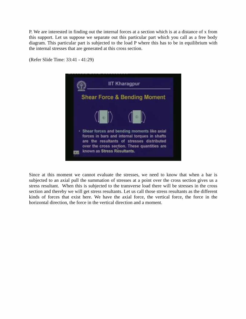
Since at this moment we cannot evaluate the stresses, we need to know that when a bar is subjected to an axial pull the summation of stresses at a point over the cross section gives us a stress resultant. When this is subjected to the transverse load there will be stresses in the cross section and thereby we will get stress resultants. Let us call those stress resultants as the different kinds of forces that exist here. We have the axial force, the vertical force, the force in the horizontal direction, the force in the vertical direction and a moment.

(Refer Slide Time: 35:03)
Depending on the type of loading of the forces the beam member will be subjected to, we will have these quantities. Since we do not have any horizontal force component acting on this beam, the horizontal reactive force will be 0. We get this vertical internal force or the stress resultant and let us call this vertical stress resultant as the shearing force V.
At any cross section we take in this beam member, we get some stress resultant, which will hold this particular part of the body, which is free from the whole body, in equilibrium under the action of the load. We call those stress resultants which act in the vertical direction to equilibrate the vertical forces as shear forces which have internal stress resultant. We call the one that acts in the horizontal x direction as axial force and we call a moment that resists the effect of the transverse loading in terms of the bending as the bending moment.
The stress resultants that act at a section are the shear force V and the bending moment M. Let us have a proper sense of the sign and cut of this particular bar at a section which is at distance of x1 from the left end and let us take the free body part of this end which is fixed here. This is the positive x direction and this is the positive y direction and along the positive x direction we have taken normal stress. This is the positive y direction and we have taken this as the positive z direction.
To match with this criterion our axial force on this particular section is positive. The shearing force is positive over here and the moment which is anti-clockwise perpendicular to the one which projects out of the plane is positive. When we take the other part of the beam where we have the load and the corresponding actions which will balance this, we have the shear force which acts downwards, the axial force which is in the opposite direction and the moment which was anti-clockwise will be clockwise here.
Let us suppose we just take an element out from this particular beam and if we look into that particular element then we get the kinds of forces which we call as positive. This shear on the

right face is upward, on the left face is downward and the axial face on the right side points towards the positive x direction and on this side towards the negative x direction and this is the moment which is anti-clockwise here and clockwise on this face.
This is what we call as the positive sign convention and its reverse is the negative sign convention. This is a small part where on the right phase we have the positive shear which acts in the upward direction. This is the moment which is anti-clockwise, this is the shear which goes down and this is the moment on the other face. So, this is the positive action and its reverse is the negative action.
Shear forces and the bending moments like axial forces in bars and internal torques in shafts, are the resultants of stresses which are distributed over the cross section and these quantities are known as stress resultants. When they are subjected to the transverse loading and when we need to evaluate the internal stresses if we take sections, there will be stress resultants because we cannot at the moment evaluate the stresses directly.
We are dealing with the resulting force that acts in the cross section and they are the forces in the vertical direction which is the shear force. The force in the horizontal direction is axial and the one which acts along the axis of the bar and the moment which resists this external load in terms of the bending, is the bending moment. So, we are interested in a beam to evaluate the value of such shear force and the bending moments because of the transverse load that the beam is subjected to for different kinds of supports. Once we compute this shear force and the bending moment, then subsequently we can compute the values of the stresses in the bar or the beam.
(Refer Slide Time: 41:30-43:04)
Let us take some examples where we need to evaluate the reactive forces and consequently the shear force and the bending moment. Determine the reaction components of the beam which are

caused by the applied loads as shown in the figure. The beam on one end is supported on a hinge and on the other end it is supported on a roller. This is a simply supported beam as we have designated. Let us look at the type of loading that it is subjected to.
Here it is subjected to a linearly varying load from 0 at this point to 2 N/mm at this point and to 0 over here. These are all in millimeters and this particular length of 900 mms from 0 is going to 2 N/mm and again it comes back to 0. At this particular point it is subjected to a constant moment which is 150 Nm which we have designated as a concentrated moment. We will have to determine the reaction components for this beam. First let us draw the free body diagram of this particular beam.
(Refer Slide Time: 43:05 - 49:58)
If we look into the free body diagram of the beam we have reactive components. For a hinge support we have a vertical reaction and a horizontal reaction. Let us call this reactive force as RA and this as HA and here we have the vertical reactive force over the roller which is RB. Since in the horizontal direction it is allowed to move and there is no horizontal force component over there we will have only the vertical component. Since at both the ends the beam is allowed to rotate there is no need for having any moment to hold this rotation back. Hence there are no reactive moments.
The reactive forces are HA, RA and RB. These are the three unknown quantities which have to be evaluated from the given loading, employing the equations of statics. Summation of horizontal forces equals to 0, summation of vertical forces equals to 0 and summation of moment equals to 0, which are the three equations of our static equilibrium. If we employ the summation of horizontal force which equals to 0 then here since we do not have any horizontal loading in the beam we get HA = 0. If we take the summation of vertical forces equals to 0 then the vertical

forces we have are the reactive forces RA + RB and since RA and RB are pointing upwards both are added. Then let us add the other quantities.
The loads triangularly vary as this is 0, this is 2 over a length of 300 and so the load is 1/2 multiplied by 300 multiplied by 2 n per mm. This particular load points downward and this reactive load RA and RB point upwards and with the minus sign. If we take this particular part of the triangular loading then ½ multiplied by 600 mm multiplied by 2 is the loading and since this loading is directed downwards this is negative and so this is 0. From this we get RA + RB = 2; 2 and 2 get canceled and we get 300 + 600 = 900n which is equation 1.
We can generate another equation from the summation of moment which equals to 0. Let us take the moment of all the forces with reference to this particular point say point A. If we start from this end the moment of RB causes an anti-clockwise moment. We have RB multiplied by 1500 mm which is anti-clockwise. Then we have a concentrated moment which is also anti-clockwise. This is plus 150 multiplied by 10 to the power of 3 nmm. Then we have these forces which will have the moment with reference to A and at this moment the load acts vertically downwards which is why this with reference to point A will cause a clockwise moment. We have considered these two anti-clockwise moments as positive. So, contribution of this moment will be negative.
Let us take this particular load which is ½ (300) multiplied by 2 which is 300 and 300 acts at a point which is one third from here and so the distance from here is 2/3 (300). The load is ½ multiplied by 2 multiplied by 300 and so this is -300 multiplied by 2/3 (300). Thus the contribution of this particular loading is ½ (600) multiplied by 2. This is again 600 in a clockwise direction. The external of this load is 1/3 from this end. Now from here to here it is 600 and this particular distance is 200 and the distance from here is 300.
So, the total distance of this load from this end is 500 and this is multiplied by 500 which equals to 0. If we remove this particular part wherein we have one equation, RA + RB = 900n the second equation RB = 0 gives us a value of RB = 140n. If you compute this we will get the value of RB from this expression as 140 n. Here RA + RB = 900 gives us RA value as 900 - RB which is 140n and this is equal to 760 n. This is the value of the reactive forces RA and RB and HA which equals to 0. The results or the three reactive forces that we have are RA = 760 n, RB = 140 n and HA = 0.

(Refer Slide Time: 49:59 - 51:16)
Let us take another example where we have to evaluate the reactive forces, the shear force V and bending moment M at C which is at a distance of 0.5 meters from point A. So, we will have to evaluate the shear force and bending moment at this point and we will have to find out the reactive forces. This particular beam is fixed at this end and free at the other and as designated, this particular beam is known as a cantilever beam.
This beam is fixed at one end, free at the other and is subjected to uniformly distributed loading over a distance of 2m and a concentrated loading at a distance of 1m from support A. So, a cantilever beam is subjected to this load. First we will have to find out the reactive forces and secondly at this section we will have to find out the shear force, the stress resultants, shear force V and bending moment M.
(Refer Slide Time: 51:17 - 56:27)
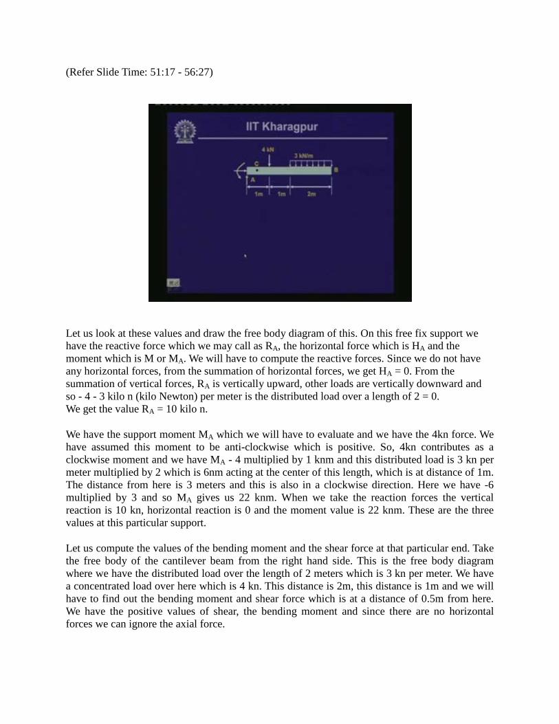
Let us look at these values and draw the free body diagram of this. On this free fix support we have the reactive force which we may call as RA, the horizontal force which is HA and the moment which is M or MA. We will have to compute the reactive forces. Since we do not have any horizontal forces, from the summation of horizontal forces, we get HA = 0. From the summation of vertical forces, RA is vertically upward, other loads are vertically downward and so - 4 - 3 kilo n (kilo Newton) per meter is the distributed load over a length of 2 = 0. We get the value RA = 10 kilo n.
We have the support moment MA which we will have to evaluate and we have the 4kn force. We have assumed this moment to be anti-clockwise which is positive. So, 4kn contributes as a clockwise moment and we have MA - 4 multiplied by 1 knm and this distributed load is 3 kn per meter multiplied by 2 which is 6nm acting at the center of this length, which is at distance of 1m. The distance from here is 3 meters and this is also in a clockwise direction. Here we have -6 multiplied by 3 and so MA gives us 22 knm. When we take the reaction forces the vertical reaction is 10 kn, horizontal reaction is 0 and the moment value is 22 knm. These are the three values at this particular support.
Let us compute the values of the bending moment and the shear force at that particular end. Take the free body of the cantilever beam from the right hand side. This is the free body diagram where we have the distributed load over the length of 2 meters which is 3 kn per meter. We have a concentrated load over here which is 4 kn. This distance is 2m, this distance is 1m and we will have to find out the bending moment and shear force which is at a distance of 0.5m from here. We have the positive values of shear, the bending moment and since there are no horizontal forces we can ignore the axial force.

If we take the summation of the vertical forces then V + 4 kn + 3 multiplied by 2 is the distributed loading. This gives us a value of V as equal to -10 kn. The sign negative indicates that it acts in the opposite direction as we have assumed. Take the moment of the forces about this particular point say MC. This is in the anti-clockwise direction and 4 kn also causes a moment in the anti-clockwise direction and we have + 4 multiplied by 0.5. This load also causes a moment in an anti-clockwise direction. So, MC + 4 multiplied by 0.5 + 3 multiplied by 2 multiplied by the distance which is 2.5 equals to 0. This gives us a value of MC + 2 + 15 = 0. So, MC = -17 knm.
The shear force which acts at this particular cross section is 10 kn and the bending moment at this cross section is 17 knm. From the values of the reactive forces that we have computed, we can find out the values of the shear force and the bending moment which should be identical. We can take the free body of either part and compute the values of the shear force and the bending moment at that particular location. We have another problem in which the beam ABCD has overhangs at each end and carries a uniform load of intensity q. For what ratio b/L will the bending moment at the midpoint of the beam be 0? Try to solve this problem.
(Refer Slide Time: 56:28 - 56:46)

(Refer Slide Time: 56:47 - 57:15)
We have another problem in which we have to determine the value of shear force and the bending moment at a point which is at a distance of 2m from here and here a force which acts at a distance of 1m from A will produce a moment over here. For these you have to compute the values of the reactive forces and thereby the shear force and the bending moment. In this particular lesson we have introduced the concept of beam, its type and the different types of supports and loads that the beam member is subjected to. Then we have evaluated the shear force and the bending moment in beams. We have looked at some examples to evaluate the reactive forces, shear force and bending moment for different types of loading.

(Refer Slide Time: 57:16 - 57:40)
(Refer Slide Time: 57:41-58:15)
The following questions are set for you. What is the difference between a bar and a beam? What are the different types of supports that are used in beams and what is the sign convention for shear force bending moment and axial force? You will find the answers to these questions once you go through this particular lesson. We will discuss the answers in the next lecture.