Embed Size (px)
Citation preview
1
Strengthening metallic bridges
Network Rail’s experiences
Brian Bell
2
Presentation outline
• Network Rail’s metallic bridges• Why do we strengthen metallic bridges?• Network Rail case studies• Further reading• Conclusions
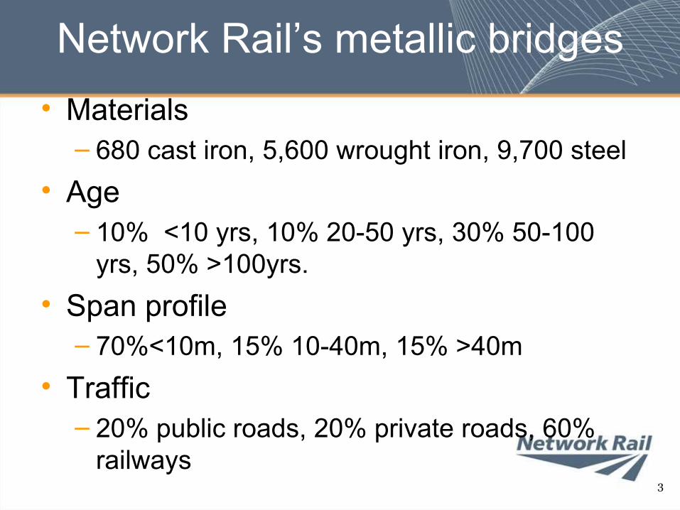
Network Rail’s metallic bridges• Materials
– 680 cast iron, 5,600 wrought iron, 9,700 steel• Age
– 10% <10 yrs, 10% 20-50 yrs, 30% 50-100 yrs, 50% >100yrs.
• Span profile– 70%<10m, 15% 10-40m, 15% >40m
• Traffic– 20% public roads, 20% private roads, 60%
railways3
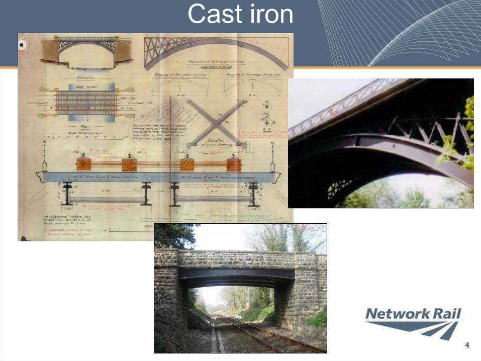
Cast iron
4
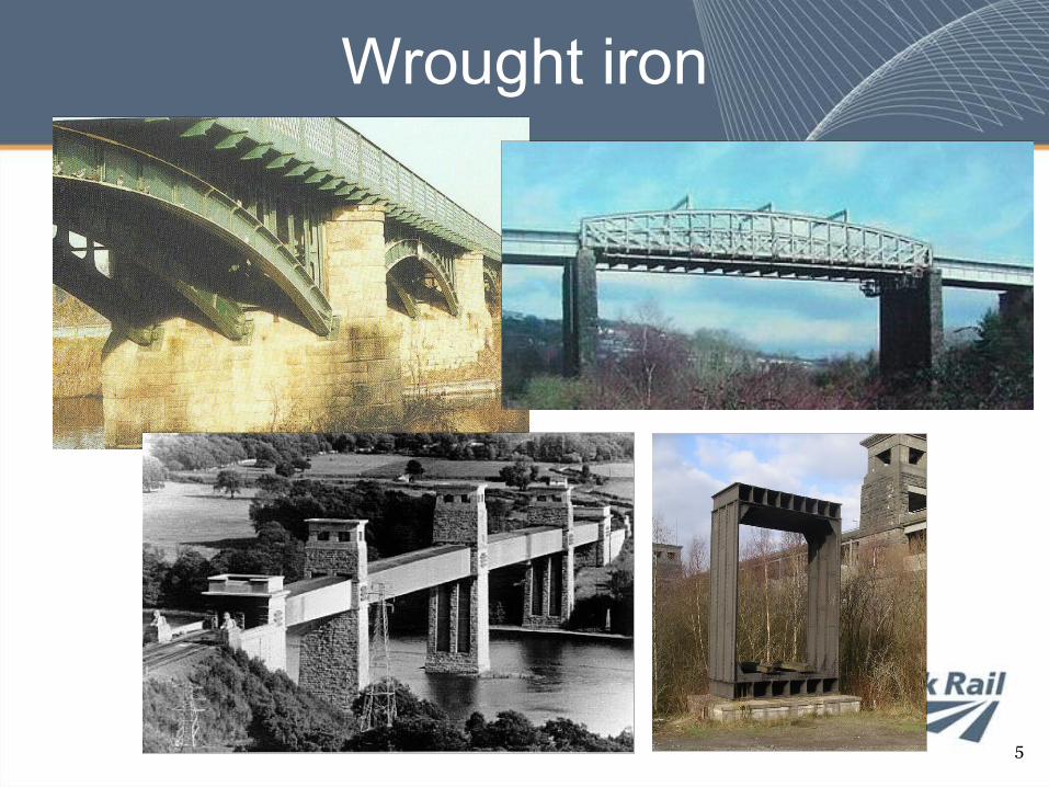
Wrought iron
5
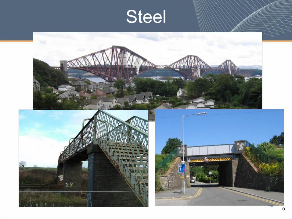
Steel
6
Why strengthen?• Long term
– To deal with under design– To deal with increased loading
• Heavier axle weights, higher speeds, increased ballast depth
– To extend fatigue life by reducing live load stresses– To deal with deterioration/damage
• Short term– To minimise disruption by spreading planned
reconstructions• But mainly to avoid reconstruction
7
Network Rail case studies
• Underline bridges– Flexural and shear deficiencies treated by the
addition of new steel• Standard solutions• Bespoke solutions
• Overline bridges– Flexural deficiencies treated by the use of
CFRP plates• Bespoke solutions
8
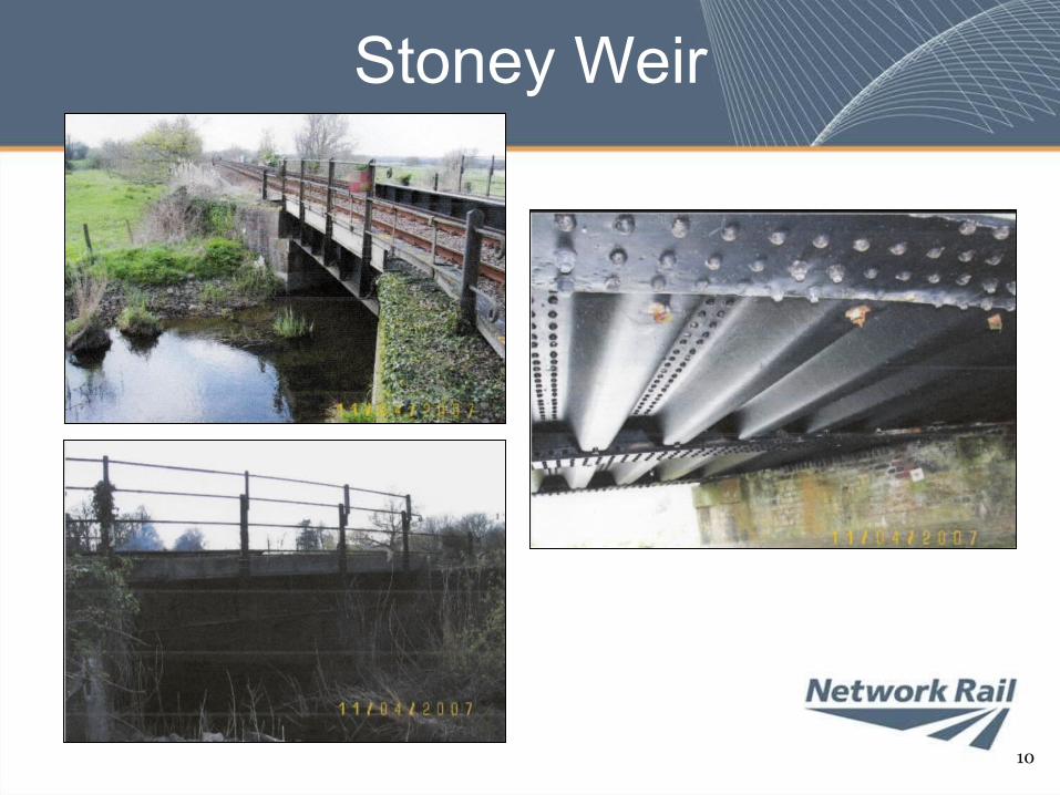
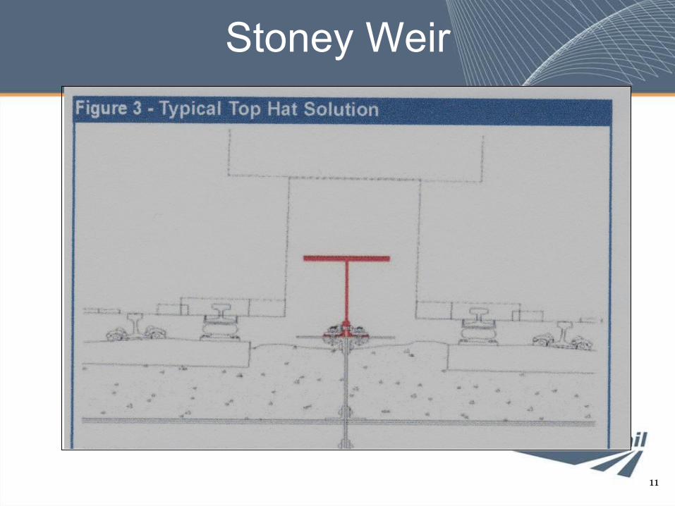
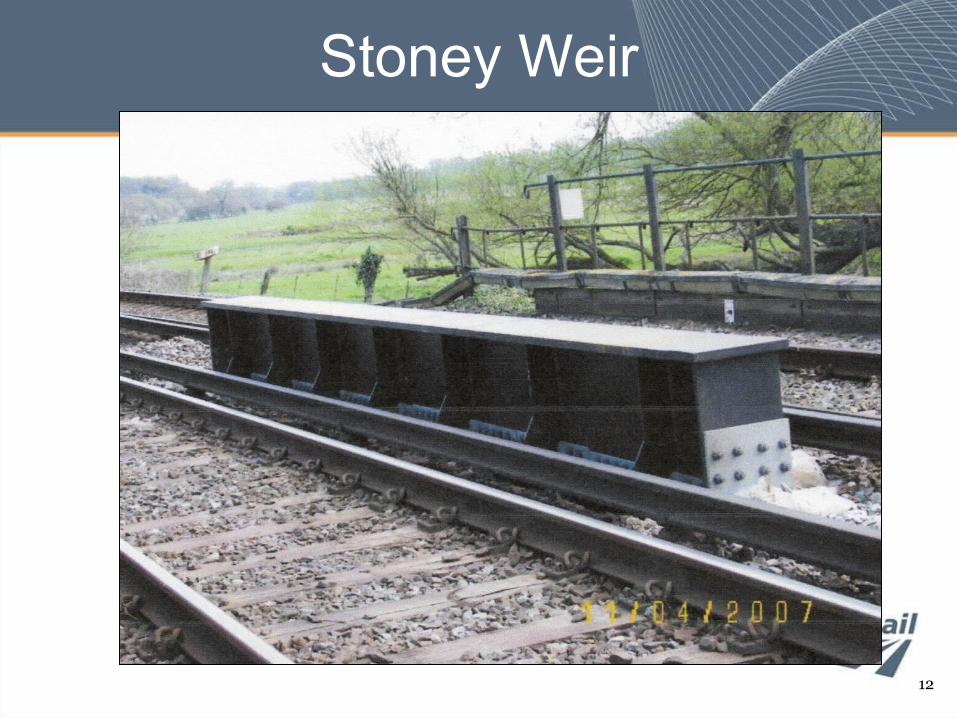
Stoney Weir
• Typical small span steel or wrought iron bridge– Three equally dimensioned main girders and
pressed steel trough decking• Centre girder weak
– Partly due to historic use by lightweight EMU traffic
• Standard “top hat” solution used• Three similar bridges dealt with as one
contract at a total cost around £300k
Stoney Weir
10
Stoney Weir
11
Stoney Weir
12
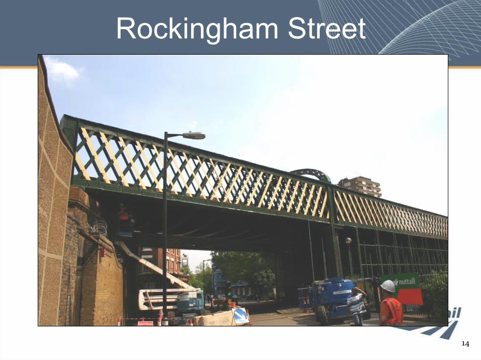
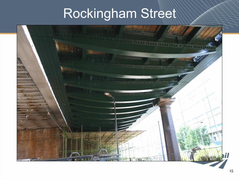
Rockingham Street
• 1890s wrought iron bridge, carrying principally suburban EMUs and weekend engineering trains.
• Cross girders weak in shear and bending• Reconstruction estimate £3.5m• Modified “top hat” solution, known as a
“bottom hat”, possible as adequate headroom available.
• Bridge now full strength, final contract cost around £1m.
Rockingham Street
14
Rockingham Street
15
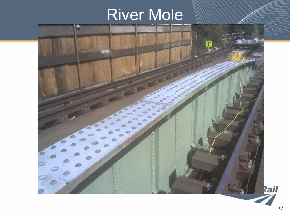
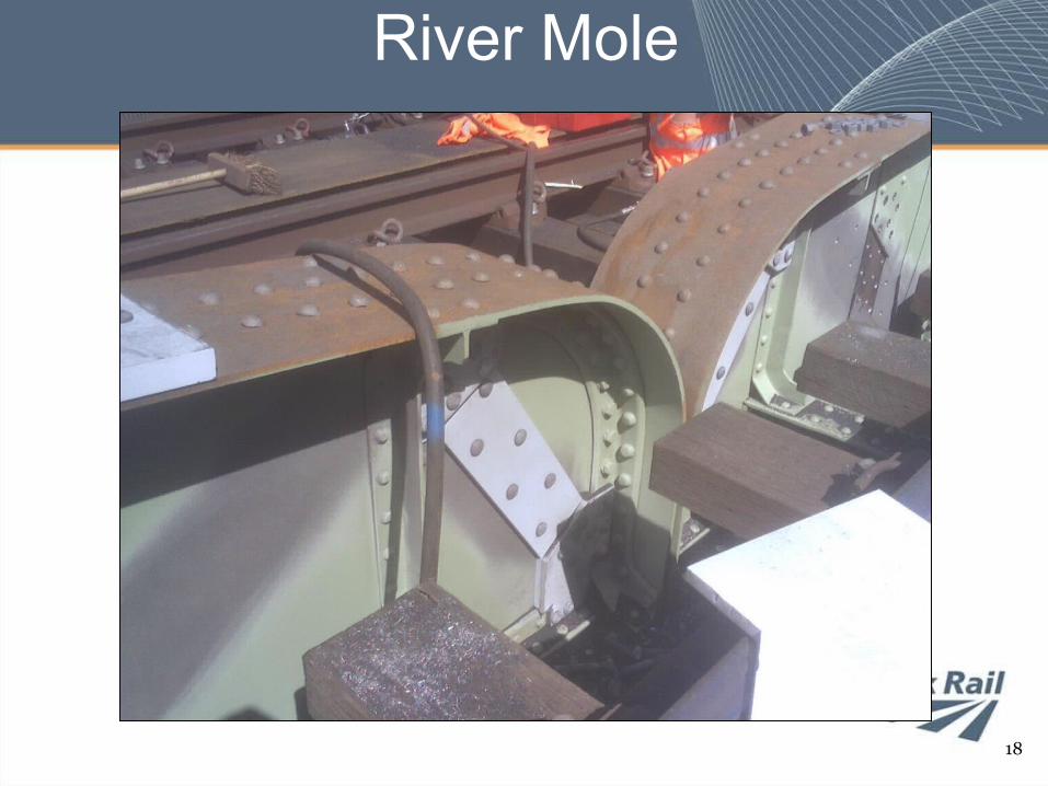
River Mole
• 3 span wrought iron bridge built around 1880– External main girders trusses
• Full strength– Inner main girders fish bellied plate
construction• weak in compression and shear.
• Top flange strengthened with extra plates• Web strengthened with discrete plates to
resemble a truss. • Total cost £800k
River Mole
17
River Mole
18
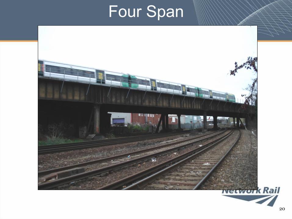
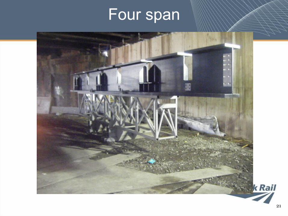
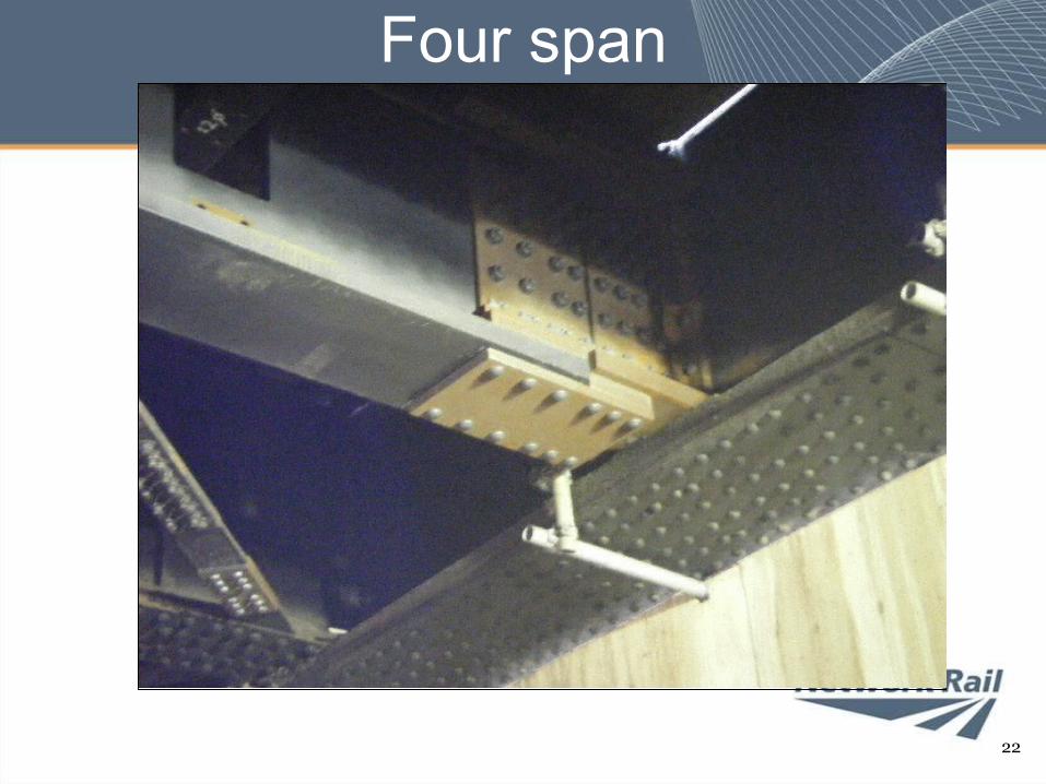
Four span• Built 1866 using wrought iron plate girders
– Carries 3 tracks of main London to Brighton line over a secondary route.
– As name implies, 4 spans consisting of main girders, cross girders and rail bearers
• Cross girders weak– Additional cross girders fabricated to fit around main
girders.– New cross girders installed during 54hr weekend
closures of lower route– Bolted in position mid week with trains running on
main line• Had main line been lower tracks this option
would have been feasible
Four Span
20
Four span
21
Four span
22
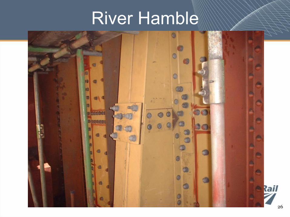
River Hamble
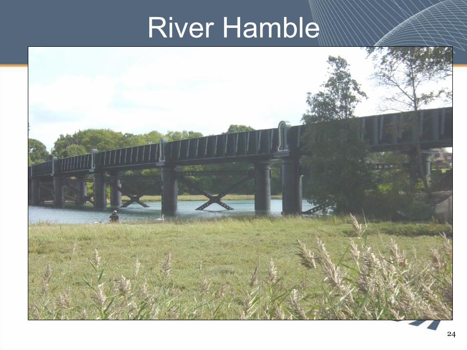
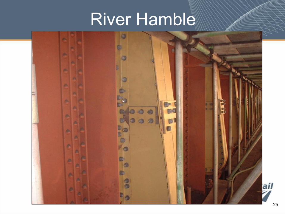
• 1890s built 6 span wrought iron bridge over tidal river• Plate main girders, cross girders and pressed troughing flooring
– Main girders theoretical zero live load capacity• Lateral torsion buckling of compression flange and web shear
deficiencies– Cross girders not aligned with main girder stiffeners
• New stiffeners provided at each cross girder location– To provide “U” frame action– Each fabricated in 24 parts to facilitate man handling into
position– Installed during standard 8hr overnight weekend line closures
• Over 350 tons of steel added and over 35,000 bolts utilised
• Final project cost (including repainting) £3.5m– Total time on site about a year
River Hamble
24
River Hamble
25
River Hamble
26
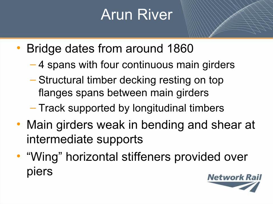
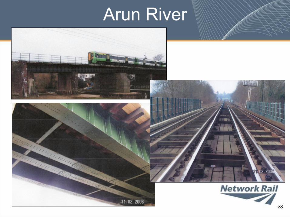
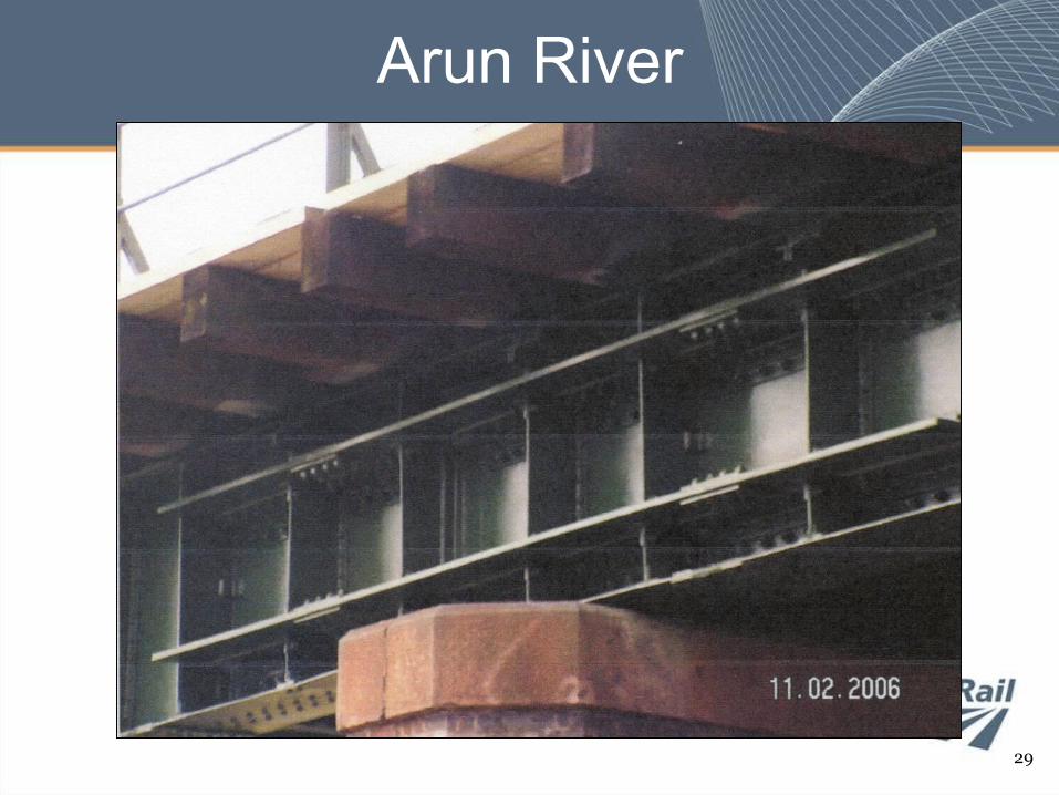
Arun River
• Bridge dates from around 1860– 4 spans with four continuous main girders– Structural timber decking resting on top
flanges spans between main girders– Track supported by longitudinal timbers
• Main girders weak in bending and shear at intermediate supports
• “Wing” horizontal stiffeners provided over piers
Arun River
28
Arun River
29
Jamestown Viaduct
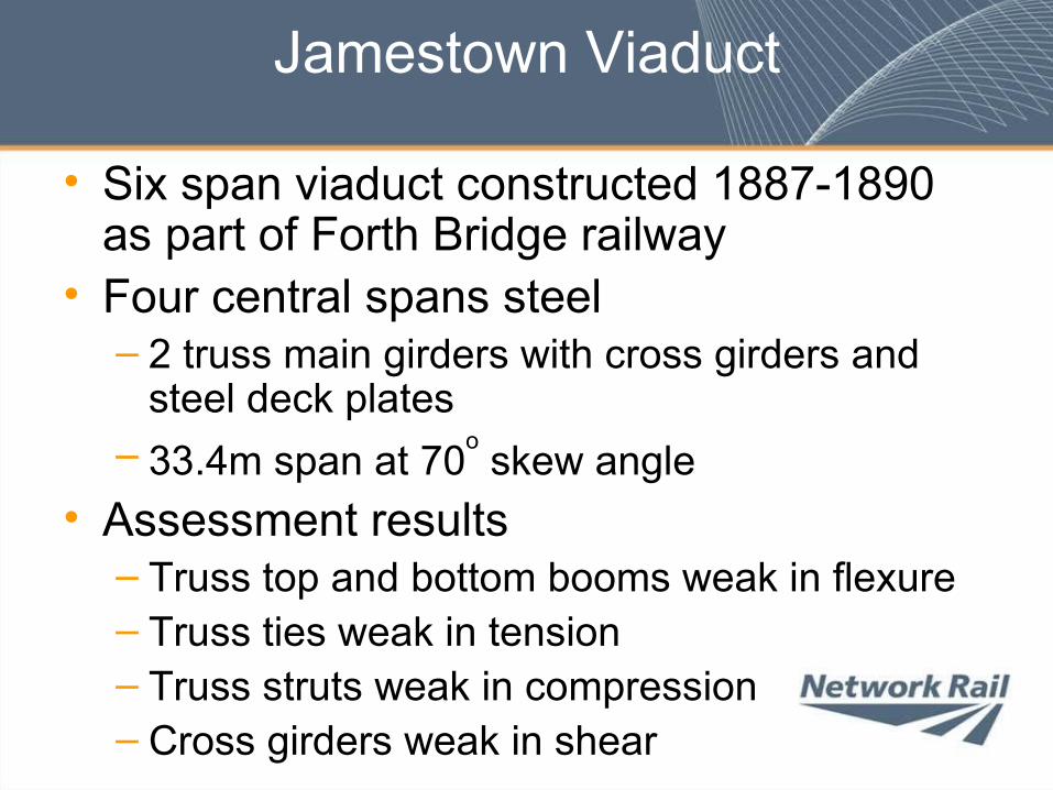
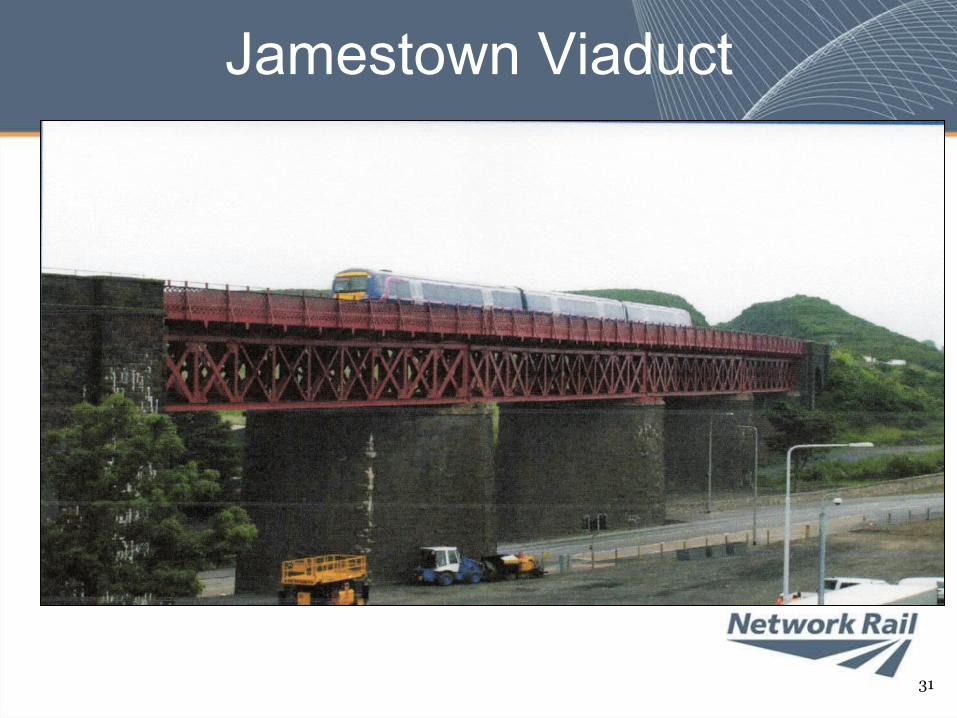
• Six span viaduct constructed 1887-1890 as part of Forth Bridge railway
• Four central spans steel – 2 truss main girders with cross girders and
steel deck plates– 33.4m span at 70o skew angle
• Assessment results– Truss top and bottom booms weak in flexure– Truss ties weak in tension– Truss struts weak in compression– Cross girders weak in shear
Jamestown Viaduct
31
Jamestown Viaduct
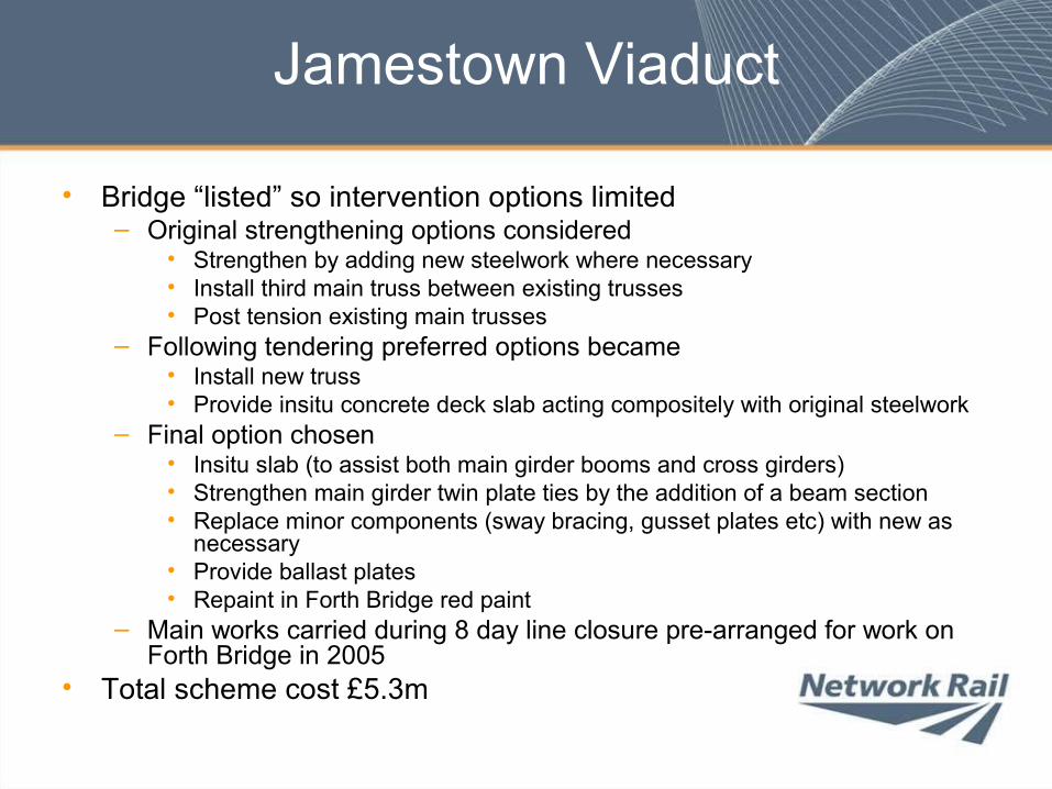
• Bridge “listed” so intervention options limited– Original strengthening options considered
• Strengthen by adding new steelwork where necessary• Install third main truss between existing trusses• Post tension existing main trusses
– Following tendering preferred options became• Install new truss• Provide insitu concrete deck slab acting compositely with original steelwork
– Final option chosen• Insitu slab (to assist both main girder booms and cross girders)• Strengthen main girder twin plate ties by the addition of a beam section• Replace minor components (sway bracing, gusset plates etc) with new as
necessary• Provide ballast plates• Repaint in Forth Bridge red paint
– Main works carried during 8 day line closure pre-arranged for work on Forth Bridge in 2005
• Total scheme cost £5.3m
Jamestown Viaduct
33
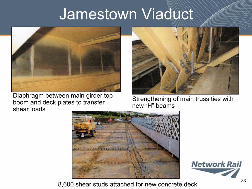
Diaphragm between main girder top boom and deck plates to transfer shear loads
Strengthening of main truss ties with new “H” beams
8,600 shear studs attached for new concrete deck
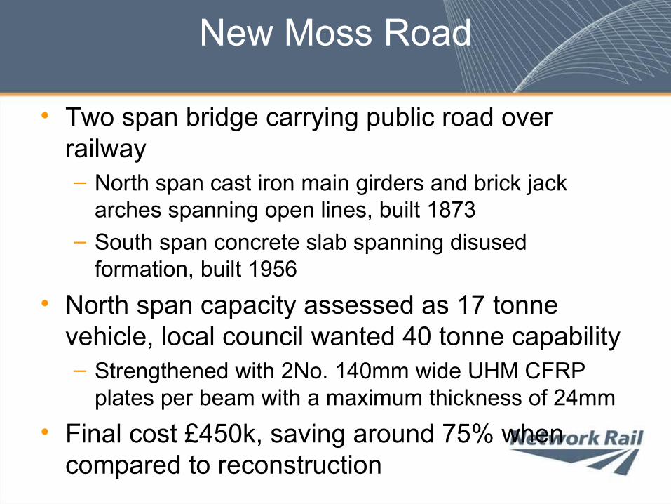
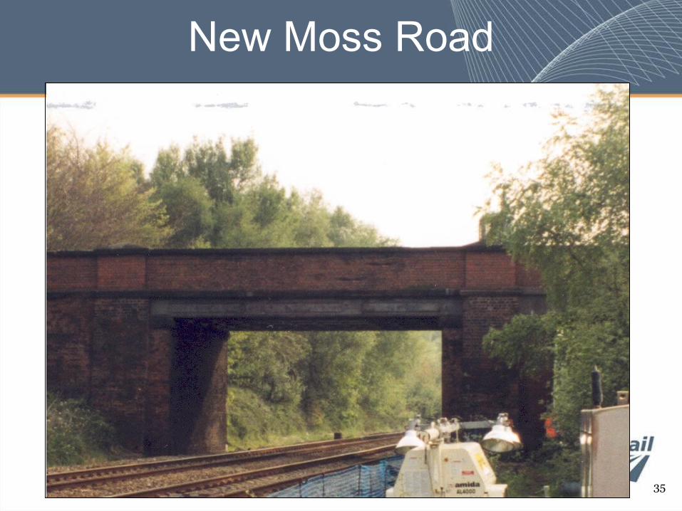
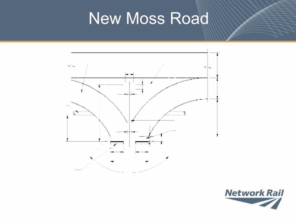
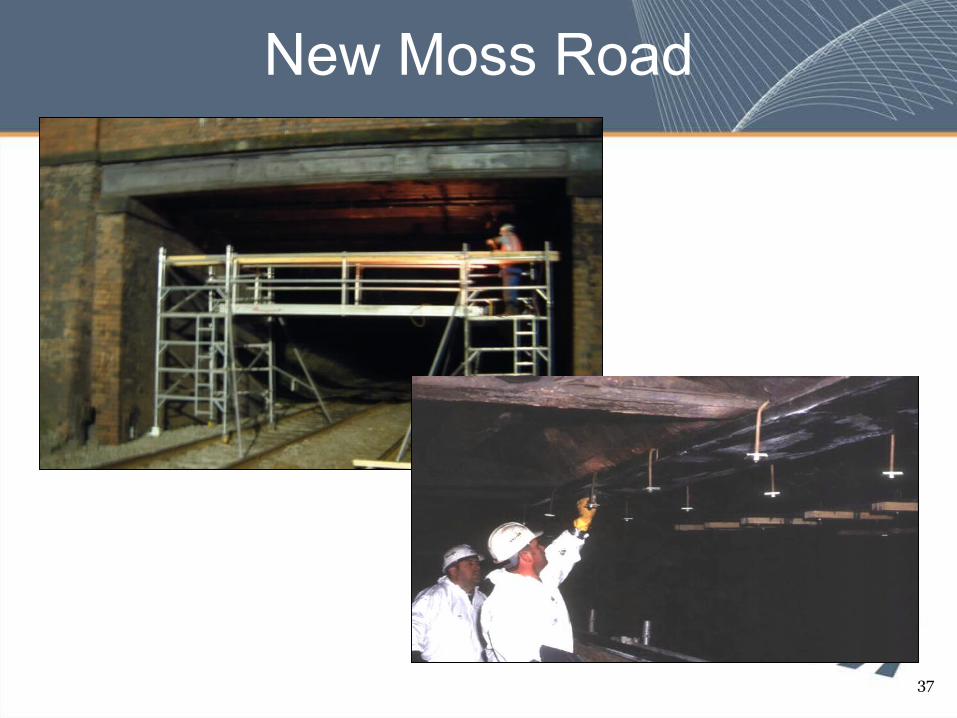
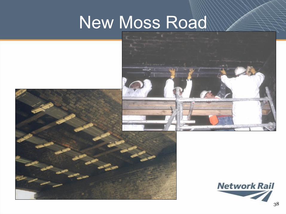
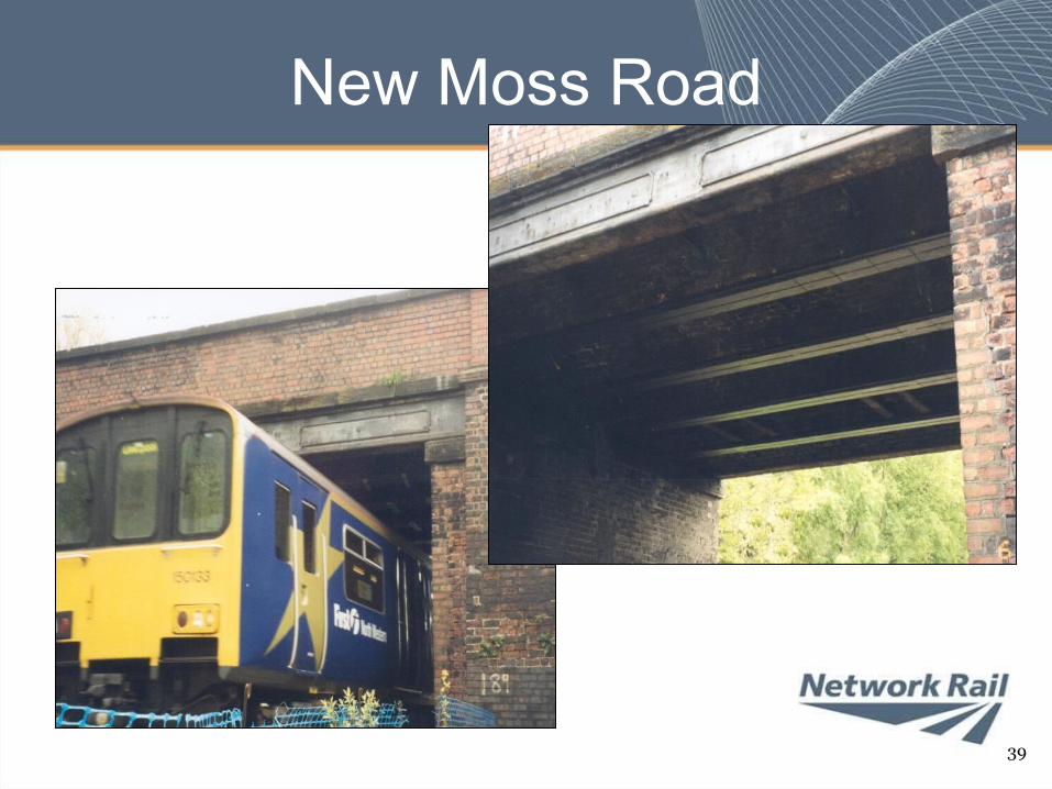
New Moss Road
• Two span bridge carrying public road over railway– North span cast iron main girders and brick jack
arches spanning open lines, built 1873– South span concrete slab spanning disused
formation, built 1956• North span capacity assessed as 17 tonne
vehicle, local council wanted 40 tonne capability– Strengthened with 2No. 140mm wide UHM CFRP
plates per beam with a maximum thickness of 24mm• Final cost £450k, saving around 75% when
compared to reconstruction
New Moss Road
35
New Moss Road
New Moss Road
37
New Moss Road
38
New Moss Road
39
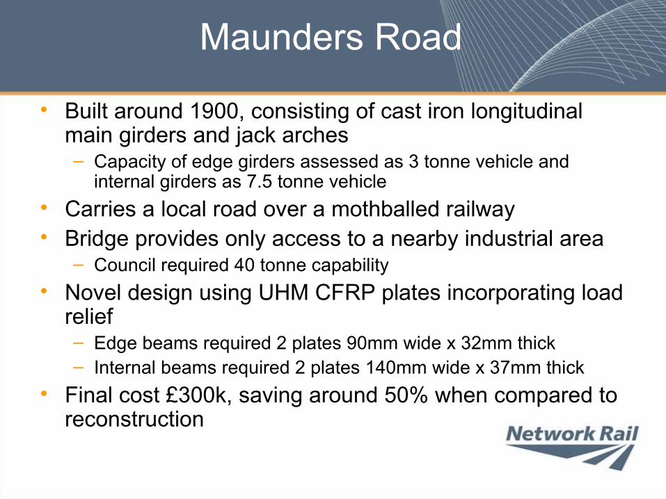
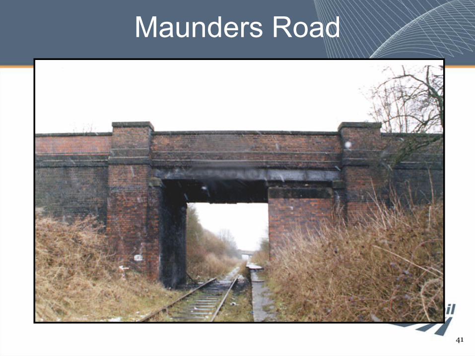
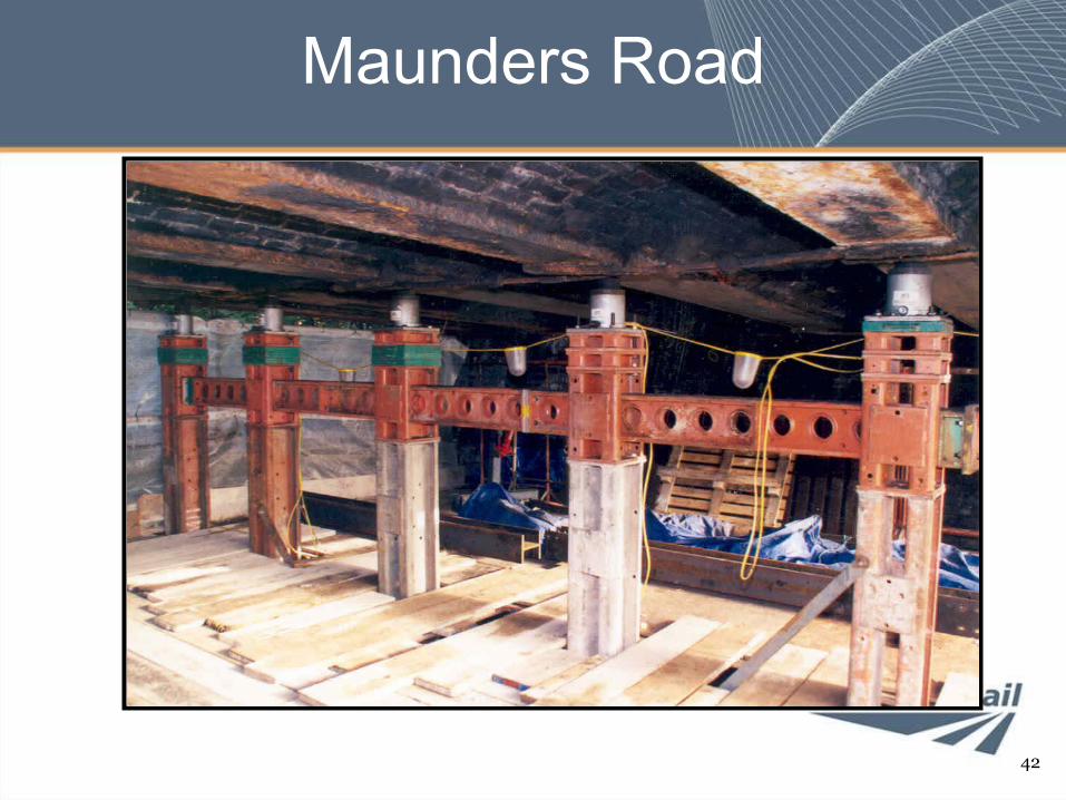
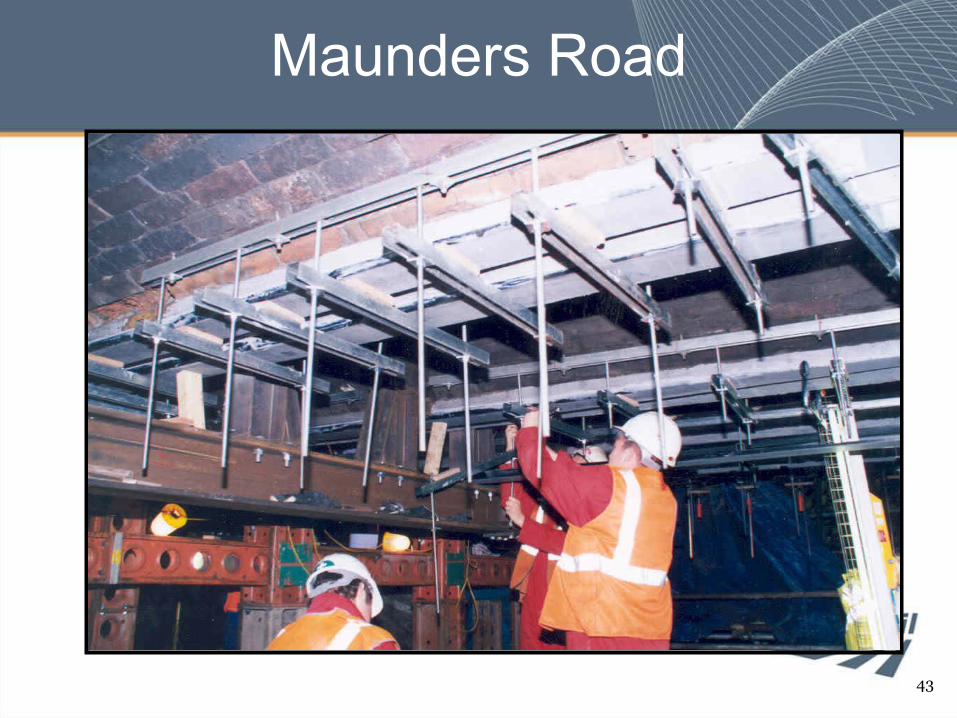
Maunders Road
• Built around 1900, consisting of cast iron longitudinal main girders and jack arches– Capacity of edge girders assessed as 3 tonne vehicle and
internal girders as 7.5 tonne vehicle• Carries a local road over a mothballed railway• Bridge provides only access to a nearby industrial area
– Council required 40 tonne capability• Novel design using UHM CFRP plates incorporating load
relief– Edge beams required 2 plates 90mm wide x 32mm thick– Internal beams required 2 plates 140mm wide x 37mm thick
• Final cost £300k, saving around 50% when compared to reconstruction
Maunders Road
41
Maunders Road
42
Maunders Road
43
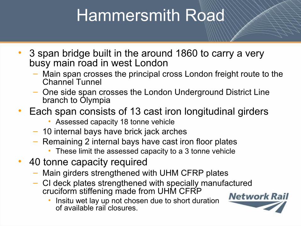
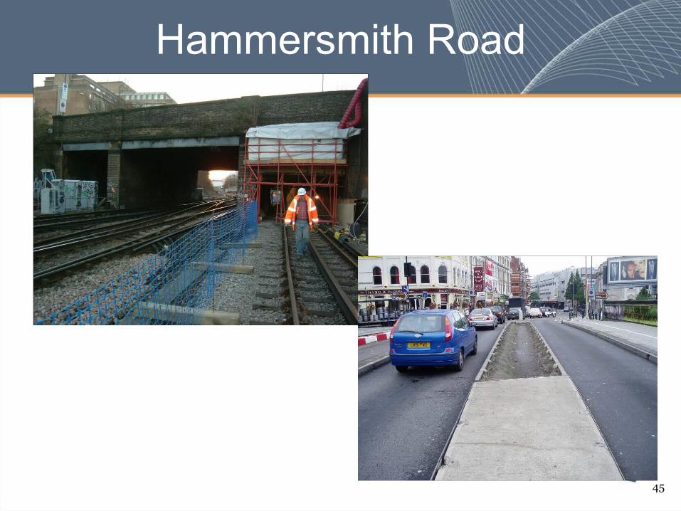
Hammersmith Road
• 3 span bridge built in the around 1860 to carry a very busy main road in west London– Main span crosses the principal cross London freight route to the
Channel Tunnel– One side span crosses the London Underground District Line
branch to Olympia• Each span consists of 13 cast iron longitudinal girders
• Assessed capacity 18 tonne vehicle– 10 internal bays have brick jack arches– Remaining 2 internal bays have cast iron floor plates
• These limit the assessed capacity to a 3 tonne vehicle• 40 tonne capacity required
– Main girders strengthened with UHM CFRP plates– CI deck plates strengthened with specially manufactured
cruciform stiffening made from UHM CFRP• Insitu wet lay up not chosen due to short duration
of available rail closures.
45
Hammersmith Road
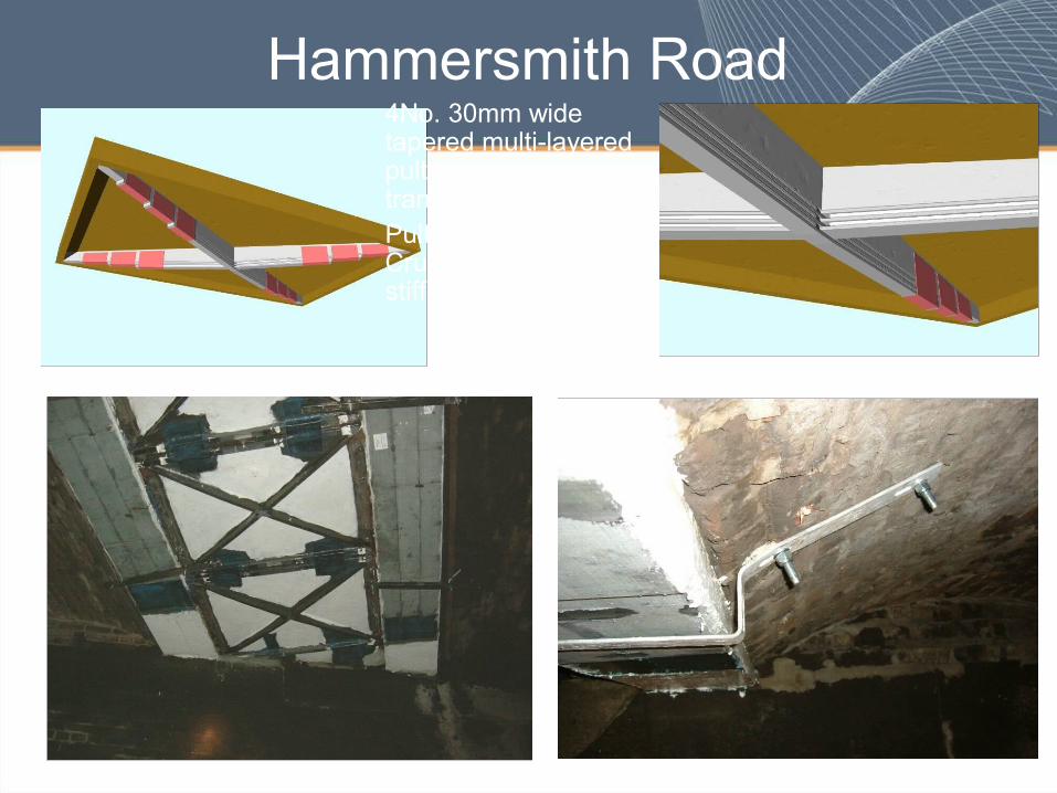
Hammersmith Road4No. 30mm wide tapered multi-layered pultruded plating to transverse stiffenersPultruded CFRP Cruciform to diagonal stiffeners
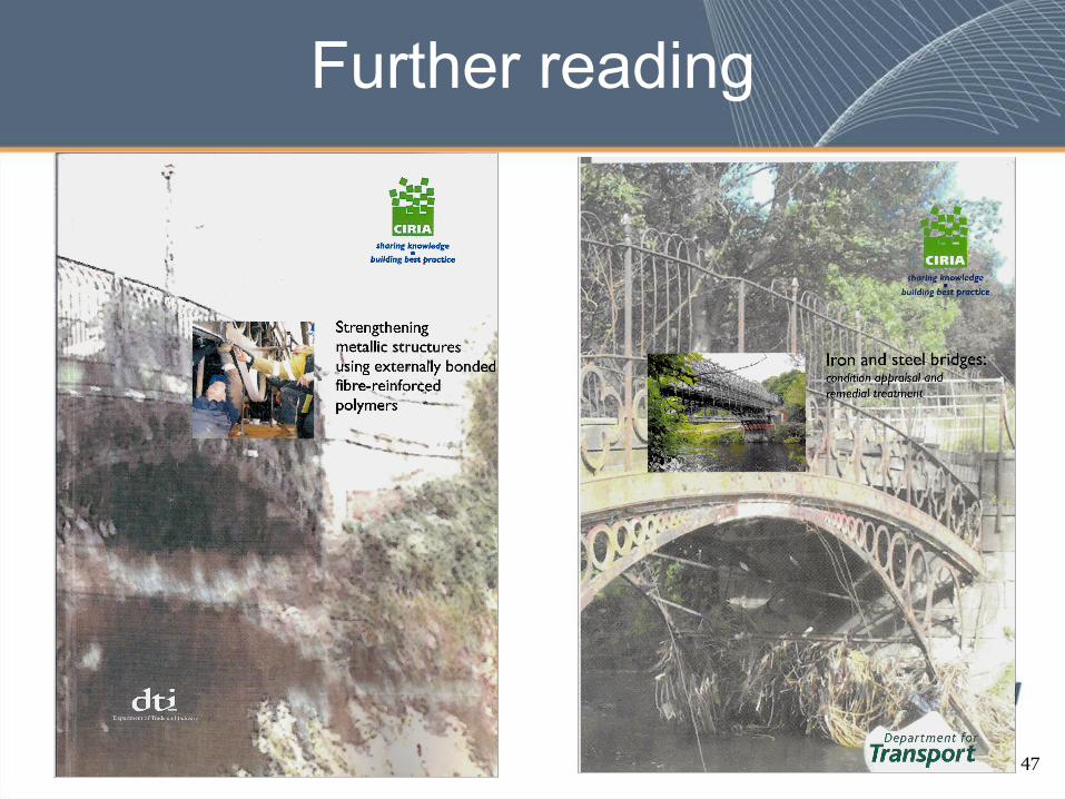
Further reading
47
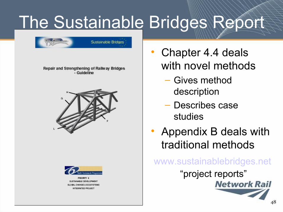
The Sustainable Bridges Report• Chapter 4.4 deals
with novel methods– Gives method
description– Describes case
studies• Appendix B deals with
traditional methods
48
www.sustainablebridges.net“project reports”
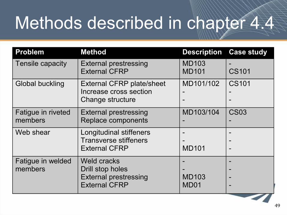
Methods described in chapter 4.4Problem Method Description Case studyTensile capacity External prestressing
External CFRPMD103MD101
-CS101
Global buckling External CFRP plate/sheetIncrease cross sectionChange structure
MD101/102--
CS101--
Fatigue in riveted members
External prestressingReplace components
MD103/104-
CS03-
Web shear Longitudinal stiffenersTransverse stiffenersExternal CFRP
--MD101
---
Fatigue in welded members
Weld cracksDrill stop holesExternal prestressingExternal CFRP
--MD103MD01
----
49
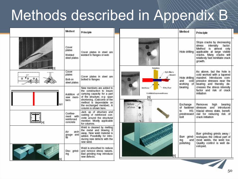
Methods described in Appendix B
50
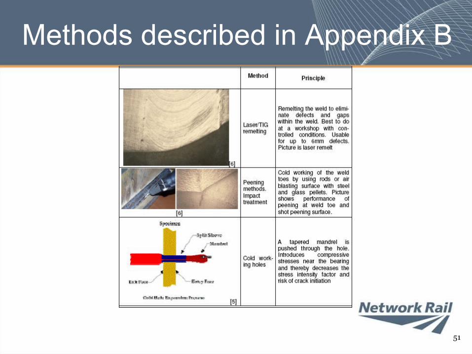
Methods described in Appendix B
51
Conclusions• Strengthening of steel bridges happens
regularly• A number of different techniques can be
employed• Traditional solutions dominate• New materials can be useful, but care
must be exercised• Because
– We don’t want to see this kind of thing …52
53
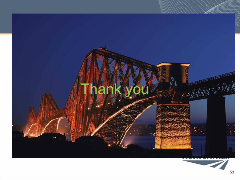
Thank you


![Strengthening of Concrete Metallic Chipsijetch.org/papers/659-EA1015.pdfcorrugated fiber Eurosteel drawn steel with high mechanical strength [10] and Dramix marketed by Bekaert [11]](https://img.pdfslide.net/doc/110x75/5f7ee9b1fc4492603729ef03/strengthening-of-concrete-metallic-corrugated-fiber-eurosteel-drawn-steel-with-high.jpg)