Embed Size (px)
Citation preview
Strengthening of Masonry Arch Bridges: Research and Applications
Proceedings of the First International Conference on Advances in Bridge Engineering
STRENGTHENING OF MASONRY ARCH BRIDGES:
RESEARCH AND APPLICATIONS
Paulo B. Lourenço, Daniel V. Oliveira
University of Minho, Portugal
Abstract
Masonry arch bridges represent an invaluable architectural and cultural heritage. Often
this heritage is insufficiently maintained and subjected to increasing traffic loads, which
leads to damage. This paper provides a survey of a dozen bridges in Northern Portugal,
recent results in FRP bond and arch strengthening, and selected case studies of repair
works in bridges in Portugal.
Keywords: Masonry arch bridges, survey, strengthening, FRP, case studies, NDT.
1.0 Introduction
Existing masonry arch bridges in Portugal were built from the Roman period to modern times. It is still possible
to find Roman bridges, characterized by their flat pavements and semicircular arches of equal dimensions, as
well as medieval bridges, with larger central spans, semicircular or pointed arches, cutwaters and humpback
pavements. The works that bridges were unavoidably submitted to across time resulted in a difficult dating,
leading sometimes to erroneous classifications. With time, the change of loads for which bridges were built, the
decay of the materials and the lack of maintenance have led to states of damage, in many circumstances not
compatible with their use or even their safety. The presence of damage, namely cracking, is not inevitably a sign
of danger, since it may produce only a redistribution of stresses, not affecting safety. Nevertheless, when damage
threatens safety of historical bridges, it becomes necessary to ensure their structural stability, by carrying out
repair and strengthening measures, motivated by both the importance they still assume in the actual road network
and the architectural, historical or social value they represent. Here, different activities carried out at University
of Minho regarding arch bridges are given, namely:
[1] A survey carried out in twelve bridges from the Northern area of Portugal, including geometrical
characterization and damage survey.
[2] A research project on the strengthening of masonry arches using FRP, including bond characterization,
according to the bond length and curvature of substrate, and tests with strengthening at the extrados and
intrados.
[3] Recent case studies carried out in Portugal, including repair measures proposed to restore safety and taking
into account the principles of intervention in structures with heritage value.
107
Strengthening of Masonry Arch Bridges: Research and Applications
Proceedings of the First International Conference on Advances in Bridge Engineering
2.0 Survey of old bridges over rivers Ave and Vizela (Portugal)
Roman bridges were planned and built in a context of a large centralized empire with a system of imperial roads,
while medieval bridges are essentially regional and result from local political and economical circumstances.
Therefore, the role of the bridge as a construction to connect different cities or regions is partially lost. In fact,
the medieval bridge assumes a border role related to administration (tax collection) and safety (defence against
invaders). Due to the limited economical and technical resources, the medieval structure shows usually a lower
number of foundations located in the river-bed. In opposition to the Roman bridge concept of arches with equal
dimensions, the medieval bridge exhibits larger flexibility, with one or several large span arches in the centre of
the bridge and progressively smaller span arches towards the ends. Often, the bridge deck was not rigorously
horizontally as in the Roman constructions due to the larger dimensions of the central arch. The building
techniques and materials were also different. The know-how related to Roman pozzolanic “concrete” was
partially lost and the medieval bridges adopt stone as the fundamental structural material with a non-structural,
non-cohesive soil infill [1]. Without the pozzolanic mortar, medieval structures resist only marginally to shear
actions. In the case of bridges, the shear action becomes particularly relevant due to the water pressure, being
this effect aggravated by the floods. For this reason, it was usual to adopt lateral flood arches and cutwaters.
Amazingly, the construction of masonry arch bridges survived until the 20th century, when this structural
solution was gradually substituted by the rapid growth of reinforced concrete and steel structural solutions.
The present study focuses on the bridges over rivers Ave and Vizela, in the Minho region, belonging to the North
of Portugal, see Fig. 1. The old roads have been analyzed and the bridges over rivers Ave and Vizela were
identified. All bridges were surveyed taking into consideration the following items: (a) localization,
(b) construction period, (c) description, (d) geometry, (e) state of conservation, (f) earlier interventions and
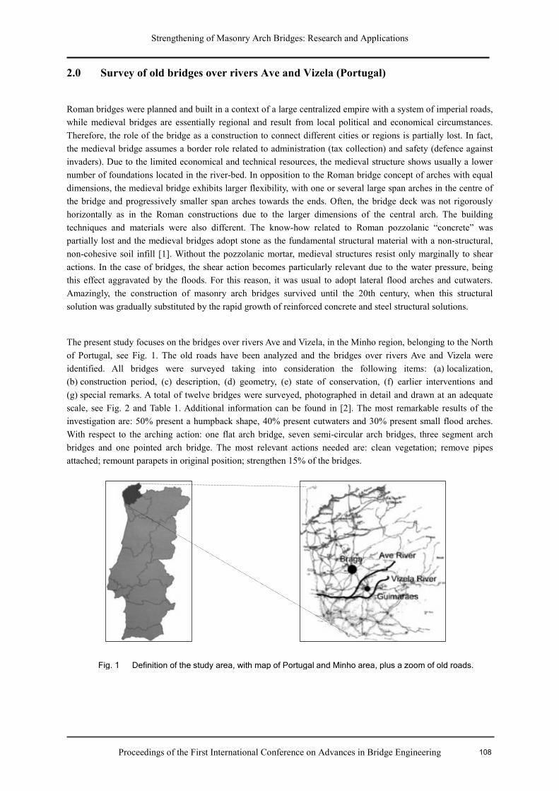
(g) special remarks. A total of twelve bridges were surveyed, photographed in detail and drawn at an adequate
scale, see Fig. 2 and Table 1. Additional information can be found in [2]. The most remarkable results of the
investigation are: 50% present a humpback shape, 40% present cutwaters and 30% present small flood arches.
With respect to the arching action: one flat arch bridge, seven semi-circular arch bridges, three segment arch
bridges and one pointed arch bridge. The most relevant actions needed are: clean vegetation; remove pipes
attached; remount parapets in original position; strengthen 15% of the bridges.
Fig. 1 Definition of the study area, with map of Portugal and Minho area, plus a zoom of old roads.
108
Strengthening of Masonry Arch Bridges: Research and Applications
Proceedings of the First International Conference on Advances in Bridge Engineering
(a) (b) (c)
(d) (e) (f) (g)
(h) (i) (j)
(k) (l)
Table I.
Information collected about the bridges
Name Arches Span Bridge Length
Road Width
Cut-water
Flood Arches
Deck Conser-vation
S. João 4 semi-circular
4 × 7.5 m 43 m 3.5 m 1 – Horizontal Regular
S. Martinho do Campo
3 semi-circular
2 × 7.6 + 8.0 m
40 m 3.2 m 2 – Horizontal Bad
Taipas 34 flat 34 × 1.2 m 62 m 3.9 m – – Horizontal Regular
Donim 3 semi-circular
9.4 + 11.8 + 6.6 m
63 m 3.4 m 2 1 Horizontal Bad
Caneiros 2 semi-circular
6.4 + 5.8 m 13 m 2.3 m – – Humpback Good
Selho 2 semi-circular
2.4 + 4.4 m 17 m 2.4 m – – Humpback Regular
Velha 3 semi-circular
3.3 + 10.8 + 8.6 m
38 m 3.2 m 2 1 Humpback Good
Pombeiro 2 seg-mental
4.3 + 10.5 m
29 m 3.4 m 1 – Humpback Regular
Domingoterres 1
pointed 16.7 m 44 m 3.0 m – – Humpback Regular
Serves 3 semi-circular
4.7 + 10.6 + 9.7 m
54 m 5.1 m – 1 Horizontal Good
EN205 1 seg-mental
18 m 35 m 4.5 m – 1 Horizontal Good
Silvares 3 seg-mental
6.4 m + 5.8 m + 6.2 m
40 m 2.3 m – – Horizontal Good
Fig. 2. View of the bridges: (a) S. João, (b) S.Martinho do Campo, (c) Taipas, (d) Donim, (e) Caneiros, (f) Selho, (g) Velha, (h) Pombeiro, (i) Domingoterres, (j) Serves, (l) EN205 and (l) Silvares.
109
Strengthening of Masonry Arch Bridges: Research and Applications
Proceedings of the First International Conference on Advances in Bridge Engineering
3.0 Strengthening of arches
Among the materials used for strengthening, there has been an increasing interest devoted to the use of FRP
(fibre-reinforced polymer) composites in the form of bonded surface reinforcements, which are being more and
more used. FRP exhibits several advantages, as low specific weight, corrosion immunity, high tensile strength,
adaptability to curved surfaces and ease of application, which makes it highly attractive and cost effective to be
used in strengthening/repair works. Old and new researches in masonry, e.g. [3, 4], do not generally adopt low
strength masonry materials. In the present testing program, handmade bricks and weak mortar were used in all
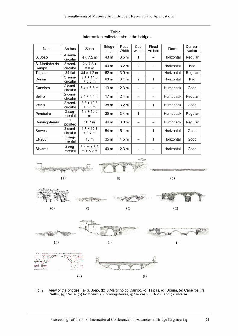
specimens in order to replicate old masonry constructions. Initially, bond tests have been carried out using four
clay bricks, see [5] for details. Fig. 3 illustrates the branch tree divisions of the experimental possibilities tested
(5 specimens of each type). The following variations with respect to the standard specimen were considered:
Masonry-FRP interface length; Anchor scheme used; FRP type of material; Masonry shape. The typical brittle
stress-displacement diagram and the stress profile are shown in Fig. 4. For a lower stress level, shear stresses are
mobilized in a relatively small interface length, close to its beginning. For higher stresses, shear stresses
developed along the entire interface, but keeping a parabolic shape stress distribution. When strip detachment
was accompanied by masonry material, optimal strength was taken from the substrate. Failure mode mechanism
is strongly dependent upon the anchorage type. An interface length of 150 mm was enough to obtain maximum
anchoring force. For the concave geometry variation, the results presented must be taken as indicative only.
Fig. 3 Different prototypes considered for the bond test.
110

Strengthening of Masonry Arch Bridges: Research and Applications
Proceedings of the First International Conference on Advances in Bridge Engineering
The absence of the force component perpendicular to the masonry surface, responsible for the strip detachment,
might reduce the figures obtained. Note that, in practice, the shape of the masonry surface can be hardly
considered as plain.
The experimental program includes also the testing of eight scaled semi-circular brick masonry arches, plain and
strengthened with GFRP strips, aiming at: Characterization of the structural behaviour of both unstrengthened
and strengthened masonry arches loaded monotonically until failure; Assessment of the influence of the
reinforcement on the mechanical behaviour and failure mechanism; Creation of a reliable database on the
experimental behaviour of masonry arches, able to be used in the calibration of both analytical and numerical
tools. Each semi-circular single-ring arch was composed of 59 brick courses and had a 750 mm radius, 500 mm
width and 50 mm thickness (thickness/span ≈ 1/30). The mortar joints were kept with a constant intrados
thickness of approximately 10 mm. The first set of specimens was composed by two unstrengthened arches.
Since both arches did not fall down at the end of the test, due to stability provided by the arch self-weight, it was
decided to use a localized strengthening arrangement composed of two GFRP strips of 80 mm width each, placed
over the hinges at either the intrados or the extrados, and test them again, see Fig. 5a. In addition, four
undamaged arches were strengthened with two continuous GFRP strips of 50 mm width each. Two arches were
strengthened at the intrados, and the other two were strengthened at the extrados, see Fig. 5a. All specimens were
tested for a monotonic load applied at the quarter span, until the formation of the correspondent failure
mechanism was achieved.
The unstrengthened specimens exhibited a structural behaviour characterized by the formation of the typical
four-hinge mechanism, which occurred for small displacements and just after reaching the maximum load. On
the other hand, all the adopted strengthening arrangements caused an increase in terms of load capacity.
However, new dominant failure modes were observed, namely detachment of the fibres from the arch surface
and sliding along a mortar joint, see Fig. 5b. The debonding phenomenon only affected the arches where the
GFRP strips were placed at intrados, whereas for specimens strengthened at extrados failure occurred due to
slipping of one part with respect to the other along a mortar joint. Another important feature of the continuously
strengthened specimens is the large deformation capacity exhibited prior to failure, which provides the arches
with important ductility behaviour. The experimental results show that the adopted continuous GFRP
strengthening arrangements provided an enhanced arch behaviour, with respect to the unstrengthened specimens,
both in terms of load capacity and in terms of ductility, see Fig. 5c. While specimens strengthened in the intrados
got the maximum load increase, specimens strengthened in the extrados exhibited the larger ductility.
Fig. 4 Typical responses in terms of shear stress-relative displacement diagram and stress distribution along interface length upon increasing loading.
111

Strengthening of Masonry Arch Bridges: Research and Applications
Proceedings of the First International Conference on Advances in Bridge Engineering
4.0 Case Study
4.1 Negrelos Bridge
The multi-span Negrelos Bridge is located close to Guimarães over the Vizela river. With time, the bridge has
lost its regional importance, though still assuming a great significance to the local network. The bridge has a flat
roadway, supported by three semi-circular granite stone masonry arches, with different free spans (8.0 m + 6.4 m
+ 8.0 m), as schematically represented in Fig. 6. The bridge reaches a total length of approximately 30 m and has
a roadway width of about 3.0 m. The central arch is supported by two massive piers, endowed with two
triangular cutwaters at upstream and two rectangular cutwaters at downstream. Within a governmental program
to clear the river from pollution, a drainage pipe was placed on the left shore, on top of an embankment made
beneath arch A1 and close to the left abutment, see Fig. 6 (the pipe is not visible). Both the spandrel walls and
(c) (d)
(b)
(a)
Fig. 5 FRP strengthened arches: (a) examples of location reinforcement; (b) examples of failure modes; load-displacement diagrams for (c) unreinforced arches and (d) arches strengthened in the
112

Strengthening of Masonry Arch Bridges: Research and Applications
Proceedings of the First International Conference on Advances in Bridge Engineering
the parapets were built with stone masonry, but successive repair works carried out over the years have changed
some original characteristics as it can be noticed by the parapet wall partially rebuilt with concrete blocks.
The survey carried out has showed that the bridge presented a pronounced damage state, where damage was
mostly characterized by, see Fig. 7a: extensive longitudinal cracking exhibited by the central arch (A2), close to
the downstream spandrel wall, clearly visible at the intrados. This is mainly caused by earth pressure in the
spandrel walls; lateral movements of the spandrel walls near the left abutment, which became out of plumb, most
likely originated by lack of maintenance in conjunction with increasingly heavy loads; generalized damage
caused by vegetation, spread all over the bridge; extensive cracking in the left downstream cutwater and minor
cracking in the other three cutwaters, mainly due to existing vegetation and the lack of adequate stone
interlocking. Also, some stone blocks were cracked. Most probably, some of the cutwaters were built or extended
after the construction of the bridge.
The bridge was modelled as an in-plane three-span semicircular arch bridge. The necessary geometrical data was
obtained from topographic surveying and visual inspection. In the absence of in-situ test results, the material
properties were considered to assume typical values found in similar structures, see [6] for details. Besides the
self-weight of the materials (masonry and fill), a moving load was also considered, composed by three axles
equally spaced by 1.5 m and with a 200 kN load per axle. Using a computer program developed within the rigid
block limit analysis method [7], the minimum failure load factor is equal to 1.67. Fig. 8 illustrates the associated
four hinges failure mechanism found, where both the dead and live load pressures applied to the arch, the hinges
and the thrust-line are showed. Assuming that the vehicle crosses the bridge from left to right, the minimum
Fig. 6 Negrelos Bridge (upstream view).
8.0 m 8.0 m6.4 m2.5 m 2.5 m
Arch A1 Arch A2 Arch A3
Vizela River
Fig. 7 Examples of damage: longitudinal cracking in the central arch and vegetation and cracks in the downstream cutwaters (downstream view).
113
Strengthening of Masonry Arch Bridges: Research and Applications
Proceedings of the First International Conference on Advances in Bridge Engineering
failure load factor was found for the vehicle central axle positioned at 31.9 % of the left arch free span (arch A1).
Since symmetrical geometry and vehicle are used, the same result is obtained considering that the vehicle crosses
the bridge from right to left instead.
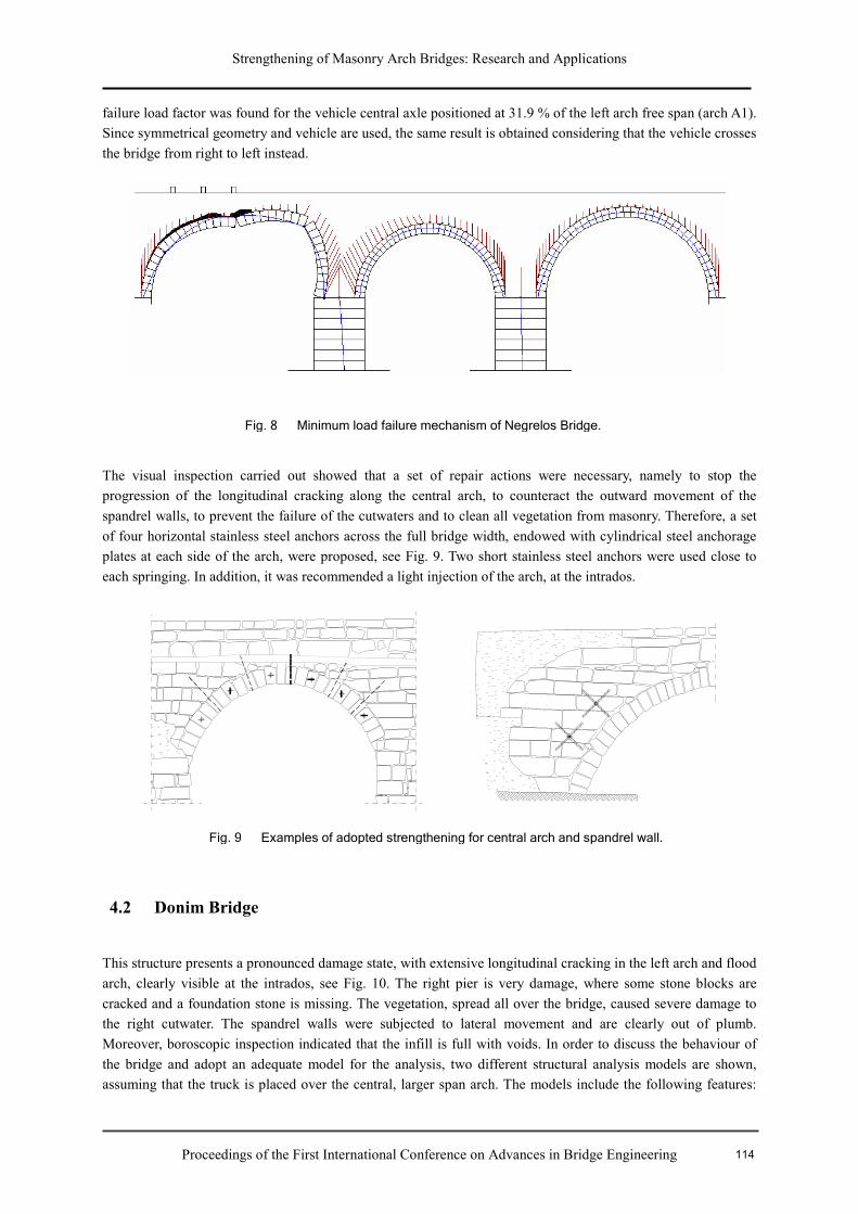
The visual inspection carried out showed that a set of repair actions were necessary, namely to stop the
progression of the longitudinal cracking along the central arch, to counteract the outward movement of the
spandrel walls, to prevent the failure of the cutwaters and to clean all vegetation from masonry. Therefore, a set
of four horizontal stainless steel anchors across the full bridge width, endowed with cylindrical steel anchorage
plates at each side of the arch, were proposed, see Fig. 9. Two short stainless steel anchors were used close to
each springing. In addition, it was recommended a light injection of the arch, at the intrados.
4.2 Donim Bridge
This structure presents a pronounced damage state, with extensive longitudinal cracking in the left arch and flood
arch, clearly visible at the intrados, see Fig. 10. The right pier is very damage, where some stone blocks are
cracked and a foundation stone is missing. The vegetation, spread all over the bridge, caused severe damage to
the right cutwater. The spandrel walls were subjected to lateral movement and are clearly out of plumb.
Moreover, boroscopic inspection indicated that the infill is full with voids. In order to discuss the behaviour of
the bridge and adopt an adequate model for the analysis, two different structural analysis models are shown,
assuming that the truck is placed over the central, larger span arch. The models include the following features:
Fig. 8 Minimum load failure mechanism of Negrelos Bridge.
Fig. 9 Examples of adopted strengthening for central arch and spandrel wall.
114

Strengthening of Masonry Arch Bridges: Research and Applications
Proceedings of the First International Conference on Advances in Bridge Engineering
Structural fill and lateral soil pressure in the spandrel walls, and non-structural fill and lateral soil pressure in the
spandrel walls. It is obvious that the lateral soil pressure could be obtained implicitly by considering inelastic
soil behaviour but this would result in a significant number of additional parameters for the analyses. For this
reason, the simplified lateral soil pressure coefficient was adopted. The results of a non-linear analysis for a
unitary load factor are illustrated in Fig 10, see also [8]. Here, the maximum principal strains are a measure of
cracking and can be assumed to indicate the expected damage in the bridge. The importance of the infill can be
immediately observed from the deformed shapes and the predicted damage in the structure. If the lateral pressure
from the infill is not considered as an external load, the spandrel walls move partly inwards, but, if the lateral
pressure is considered, the spandrel walls move outwards. Damage in the structure is also localized in different
areas. For the first model, damage occurs in the spandrel walls and, longitudinally, in the arches. For the second
model, extensive damage occurs in the spandrel walls due to out-of-plane bending.
4.3 Boutaca Bridge
The Boutaca bridge has a flat roadway, supported by six pointed masonry arches equally spanned, as illustrated
in Fig. 11. Lateral masonry walls, supported by a buttressing system, make the connection between the pointed
arches and a semicircular masonry tunnel, belonging to the old railway network. The bridge reaches a total
length of 60.0 m and has a roadway width of 7.0 m. At the ends, it is noticeable the existence of four box-houses
used by road-menders. Diagnosis was carried out with the assistance of GPR, see Fig. 11. To prevent the outward
movement of the masonry walls and to lighten the load in the buttresses, it was proposed the execution of a set of
horizontal anchors across the full width of the road, endowed with plates, which have been designed to be
aesthetically attractive. Four vertically aligned tie rods between each two buttresses were adopted. In order to
reduce the lateral pressure on the walls and the appearance of humidity at the intrados of arches it was proposed
to waterproof the pavement and the reconstruction of all the drainage system. Also, the cleaning and removal of
infesting vegetation in the bridge should be periodically carried out. The missing plaster and painting should be
replaced, using materials similar to those used in the construction.
Fig.10 Examples of damage in Donim bridge, using a non-linear finite element analysis (arch splitting or spandrel collapse).
115

Strengthening of Masonry Arch Bridges: Research and Applications
Proceedings of the First International Conference on Advances in Bridge Engineering
Acknowledgement
The financial support provided by the Portuguese Science and Technology Foundation through the
POCTI/ECM/38071/2001 project is gratefully acknowledged. FRP composites and pre-mixed mortar used in the
experiments were offered by BETTOR MBT and MAPEI, respectively, to whom the authors are grateful.
References
[1] Carita, H. and Cardoso, H. (1997). “Bridges in Portugal (in Portuguese).” Secil, Lisboa.
[2] Luís, G. and Santos, S. (1999). “Old bridges over rivers Ave and Vizela (in Portuguese).” Universidade do Minho, Guimarães.
[3] Triantafillou, T.C. (1998). Strengthening of masonry structures using epoxy-bonded FRP laminates. J. Compos. for Constr., ASCE, 2(2), 96-104.
[4] Valluzzi, M., Valdemarca, M. and Modena, C. (2001). Experimental analysis and modeling of brick masonry vaults strengthened by FRP laminates. J. Compos. for Constr., ASCE, 5(3), 163-169.
[5] Basilio, I., Oliveira, D.V., Lourenço, P.B. (2005). Experimental characterization of FRP-masonry interface behaviour, in 5th International Conference on Analytical Models and New Concepts in Concrete and masonry Structures, Gliwice,
Poland, CD-ROM.
[6] Oliveira, D.V., Lourenço, P.B. (2006). Repair of a historical stone masonry arch bridge, Third International Conference on Bridge Maintenance, Safety and Management, Porto, Portugal.
[7] Gilbert, M. (2005). Ring: Theory and modeling guide. Computational limit analysis and design unit, University of Sheffield, UK.
[8] Lourenço, P.B., Poças Martins, J.P. (2001). Survey of old bridges over Rivers Ave and Vizela (Portugal), em: Arch’01, Eds. C. Abdunur, Presses Ponts et Chaussées, Paris, p. 213-218.
t (n
s)
x (cm)
0 2000 4000 6000 8000 10000
0
10
20
30
40
50
60
70
Fig. 11 Boutaca Bridge: upstream view and detection of arch thickness and infill characteristics using GPR inspection.
116