Embed Size (px)
Citation preview
1
STRENGTHENING OF MASONRY WITH NEAR SURFACE MOUNTED FRP BARS
J. Gustavo Tumialan, University of Missouri-Rolla, Rolla, MO
Nestore Galati, University of Missouri-Rolla, Rolla, MO
Sinaph M. Namboorimadathil, University of Missouri-Rolla, Rolla, MO
Antonio Nanni, University of Missouri-Rolla, Rolla, MO
Abstract
For the retrofitting of the civil infrastructure, an alternative to Fiber Reinforced Polymer (FRP) externally-bonded laminates is the use near surface mounted (NSM) FRP bars. This technique consists of placing a bar in a groove cut into the surface of the member being strengthened. The FRP bar may be embedded in an epoxy- or cementitious-based paste, which transfers stresses between the substrate and the bar. The successful use of NSM FRP bars in the strengthening of concrete members has been extended to unreinforced masonry (URM) walls, one of the building components most prone to failure during a seismic event. This paper describes three applications of FRP bars for the strengthening of URM and reports on the obtained experimental results. In the first application, FRP bars are applied vertically to resist out-of-plane forces acting on the masonry walls (i.e. flexural strengthening). In the second application, bars are inserted horizontally in the masonry joints to strengthen the wall when subjected to in-plane forces (i.e. shear strengthening). Finally, the third application deals with the retrofitting of masonry walls showing deficient anchorage to the base beam. In this application, FRP bars are placed in the toe region of the wall acting as anchors to increase flexural capacity. In each of these three applications, the strengthening was remarkably effective.
Introduction
Unreinforced masonry (URM) walls are prone to failure when subjected to overstresses caused by out-of-plane and in-plane loads. Externally bonded FRP laminates have been successfully used to increase the flexural and/or the shear capacity of reinforced concrete (RC) and masonry members. The use of near-surface-mounted (NSM) FRP bars is an attractive method for increasing flexural and shear strength of deficient RC members (De Lorenzis et al., 2000) and masonry walls and, in certain cases, can be more convenient than using FRP laminates (i.e. anchoring requirements, aesthetics requirements). Application of NSM FRP bars does not require any surface preparation work and requires minimal installation time compared to FRP laminates. Another advantage is the feasibility of anchoring these bars into members adjacent to the one being strengthened. For instance, in the case of the strengthening of a masonry infill with FRP bars, they can be easily anchored to columns and beams.
This paper presents three applications of FRP bars for the strengthening of URM walls. In the first application, NSM FRP bars are used as flexural reinforcement to strengthen URM walls to resist out-of- plane forces. In the second application, a retrofitting technique denominated FRP Structural Repointing is described. In this technique the FRP bars are placed into the bed masonry joints to act as shear reinforcement to resist in-plane loads. Finally, in the third application, masonry walls exhibiting
2
deficient anchorage to the base beam are retrofitted by placing NSM FRP bars in the toe region of the wall which act as anchors to increase the flexural capacity of walls subject to in-plane loads.
Flexural Strengthening
FRP bars can be used as reinforcement to provide flexural capacity to URM walls. A previous investigation has shown the effectiveness of FRP bars for increasing the flexural capacity of URM walls (Hamid, 1996). In that investigation, the FRP reinforcement was internally placed, this technique demanded the cutting of slots at the top course of the wall to place the bars, drilling of holes to pump grout, and grouting. The successful use of near-surface-mounted (NSM) bars for improving the flexural capacity of RC members led to extending their potential use for the strengthening of URM walls. The use of NSM FRP bars is attractive since their application does not require any surface preparation work and requires minimal installation time. Strengthening Procedure
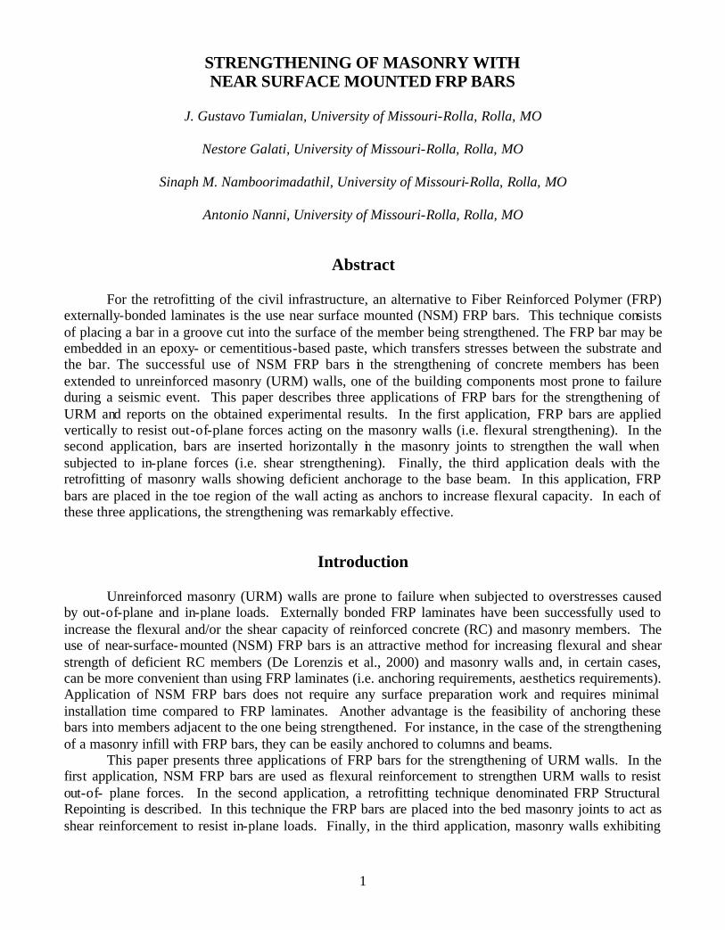
The NSM technique consists of the installation of FRP reinforcing bars in slots grooved in the masonry surface. An advantageous aspect of this method is that it does not require sandblasting and puttying. The strengthening procedure can be summarized as: (1) grooving of slots having a width of approximately one and a half times the bar diameter and cleaning of surface, (2) application of embedding paste (epoxy-based or cementitious-based) (see Figure 1a), (3) encapsulation of the bars in the groove (see Figure 1b), and (4) finishing. If hollow masonry units are the base material, special care must be taken to avoid a groove depth exceeding the thickness of the masonry unit shell, and local fracture of the masonry. In addition, if an epoxy-based paste is used, strips of masking tape or other similar adhesive tape can be attached at each edge of the groove to avoid staining of the masonry (see Figure 1).
(a) Application of Embedding Paste (b) Encapsulation of FRP Bar
Figure 1. Installation of NSM FRP Bars
Depending on the kind of embedding paste, a mortar gun for tuckpointing or an epoxy gun may be used for its application. The guns can be hand, air or electric powered, being the latter two the most efficient.
3
Experimental Results Four masonry specimens were constructed with concrete blocks using a Type N mortar. Their
dimensions were 24 in. wide by 48 in. high. The wall thickness was about 3.75 in. The average compressive strength of masonry (ASTM C1314) was 1520 psi. The masonry specimens were strengthened with #3 GFRP bars having a tensile strength of 110 ksi and modulus of elasticity of 5900 ksi. An epoxy-based paste, having a compressive strength of 12.5 ksi and a tensile strength of 4000 psi, was used as embedding material. The strengthening layout intended to represent URM wall strips with GFRP bars at different spacing. Thus, Wall 1 was strengthened with one GFRP bar (spacing = 24 in.), Wall 2 with two GFRP bars (spacing = 12 in.), and Wall 3 with three GFRP bars (spacing = 8 in.). Conversely, Wall 1S was strengthened with externally bonded GFRP laminates applied by manual lay-up. The amount of reinforcement was equivalent to that of Wall 1 in terms of axial stiffness EA (Modulus of Elasticity× FRP Gross Cross Sectional Area). Due to the brittle nature of URM it is meaningless to test an URM wall.
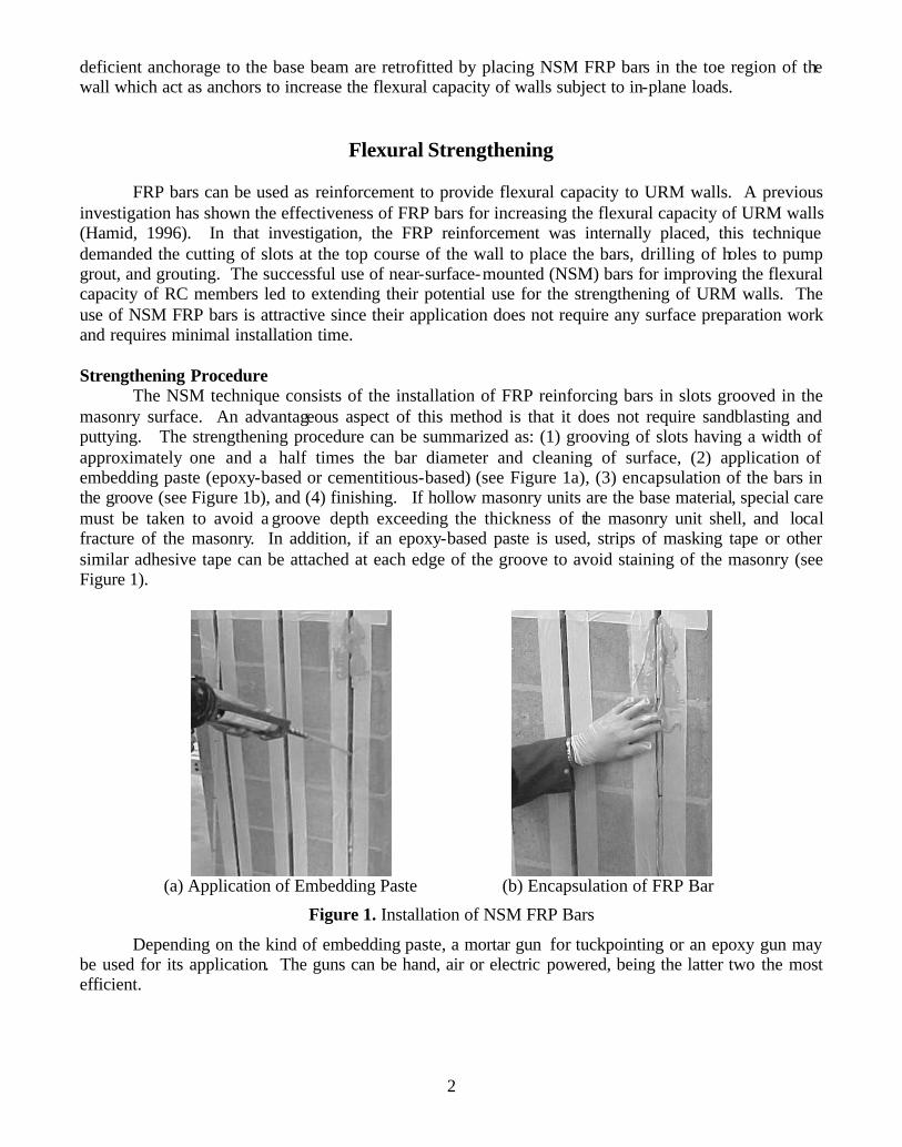
The walls were tested under simply supported conditions (see Figure 2). An out-of-plane load was applied along two load lines spaced 8 in. Linear Variable Differential Transducers (LVDTs) were placed at midspan and supports to register deflections and settlements. Also, strain gauges were placed on the GFRP bars to record strains at different levels of load.
Figure 2. Test Setup
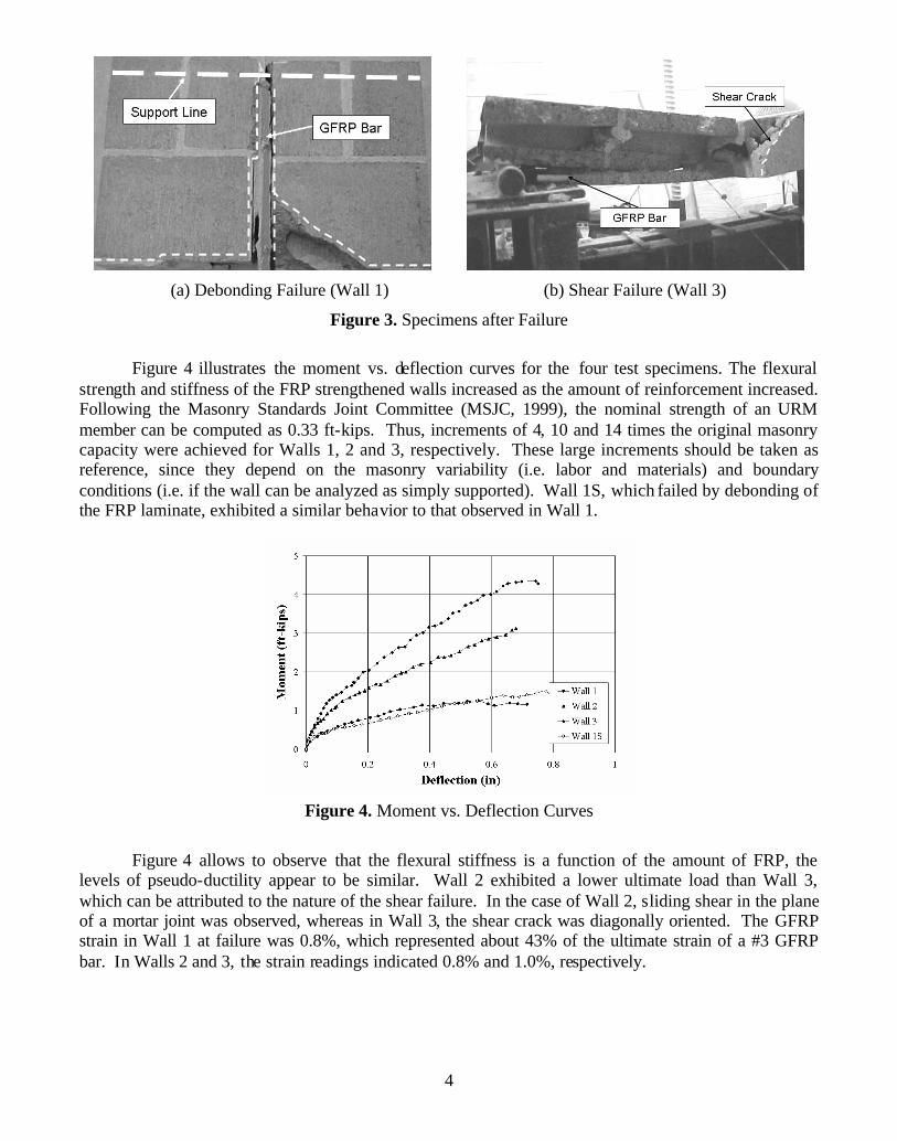
Wall 1 failed due to debonding of the embedding material from the masonry. Initial flexural
cracks were primarily located at the mortar joints. A cracking noise during the test revealed a progressive cracking of the embedding paste. Since the tensile stresses at the mortar joints were being taken by the FRP reinforcement, a redistribution of stresses occurred. As a consequence, cracks developed in the masonry units oriented at 45o (see Figure 3a) or in the head mortar joints. Some of these cracks followed the epoxy paste and masonry interface causing debonding and subsequent wall failure.
Walls 2 and 3 failed due to shear (see Figure 3b). Similarly to Wall 1, cracking started in the mortar joints at the maximum bending region. At the final stage, some debonding of the FRP bars was observed, a consequence of differential displacement in the shear plane. In general, initial cracking was delayed and the crack widths were thinner as the amount of FRP reinforcement increased.
4
(a) Debonding Failure (Wall 1) (b) Shear Failure (Wall 3)
Figure 3. Specimens after Failure
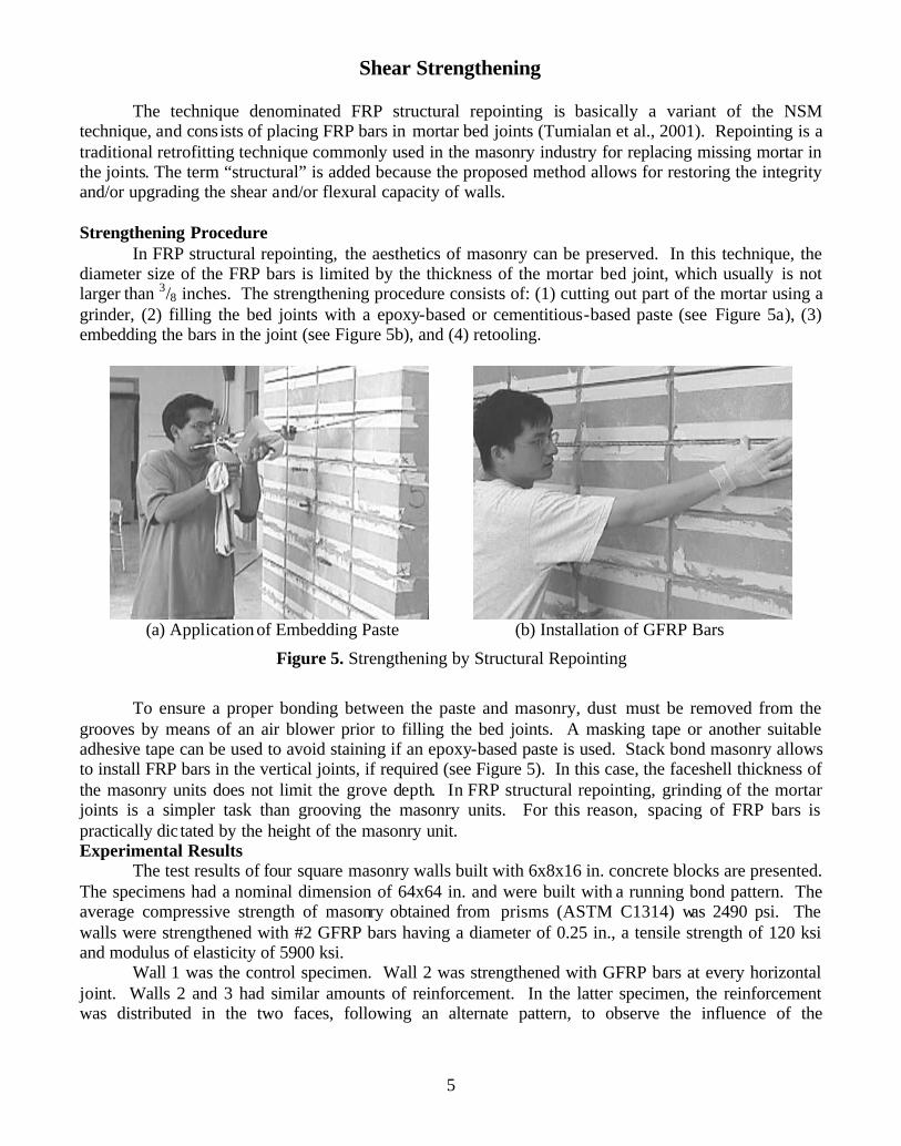
Figure 4 illustrates the moment vs. deflection curves for the four test specimens. The flexural
strength and stiffness of the FRP strengthened walls increased as the amount of reinforcement increased. Following the Masonry Standards Joint Committee (MSJC, 1999), the nominal strength of an URM member can be computed as 0.33 ft-kips. Thus, increments of 4, 10 and 14 times the original masonry capacity were achieved for Walls 1, 2 and 3, respectively. These large increments should be taken as reference, since they depend on the masonry variability (i.e. labor and materials) and boundary conditions (i.e. if the wall can be analyzed as simply supported). Wall 1S, which failed by debonding of the FRP laminate, exhibited a similar behavior to that observed in Wall 1.
Figure 4. Moment vs. Deflection Curves
Figure 4 allows to observe that the flexural stiffness is a function of the amount of FRP, the
levels of pseudo-ductility appear to be similar. Wall 2 exhibited a lower ultimate load than Wall 3, which can be attributed to the nature of the shear failure. In the case of Wall 2, sliding shear in the plane of a mortar joint was observed, whereas in Wall 3, the shear crack was diagonally oriented. The GFRP strain in Wall 1 at failure was 0.8%, which represented about 43% of the ultimate strain of a #3 GFRP bar. In Walls 2 and 3, the strain readings indicated 0.8% and 1.0%, respectively.
5
Shear Strengthening
The technique denominated FRP structural repointing is basically a variant of the NSM technique, and consists of placing FRP bars in mortar bed joints (Tumialan et al., 2001). Repointing is a traditional retrofitting technique commonly used in the masonry industry for replacing missing mortar in the joints. The term “structural” is added because the proposed method allows for restoring the integrity and/or upgrading the shear and/or flexural capacity of walls. Strengthening Procedure
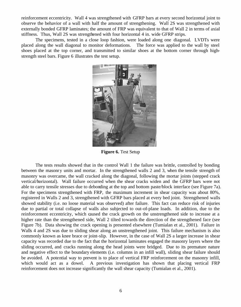
In FRP structural repointing, the aesthetics of masonry can be preserved. In this technique, the diameter size of the FRP bars is limited by the thickness of the mortar bed joint, which usually is not larger than 3/8 inches. The strengthening procedure consists of: (1) cutting out part of the mortar using a grinder, (2) filling the bed joints with a epoxy-based or cementitious-based paste (see Figure 5a), (3) embedding the bars in the joint (see Figure 5b), and (4) retooling.
(a) Application of Embedding Paste (b) Installation of GFRP Bars
Figure 5. Strengthening by Structural Repointing
To ensure a proper bonding between the paste and masonry, dust must be removed from the
grooves by means of an air blower prior to filling the bed joints. A masking tape or another suitable adhesive tape can be used to avoid staining if an epoxy-based paste is used. Stack bond masonry allows to install FRP bars in the vertical joints, if required (see Figure 5). In this case, the faceshell thickness of the masonry units does not limit the grove depth. In FRP structural repointing, grinding of the mortar joints is a simpler task than grooving the masonry units. For this reason, spacing of FRP bars is practically dic tated by the height of the masonry unit. Experimental Results
The test results of four square masonry walls built with 6x8x16 in. concrete blocks are presented. The specimens had a nominal dimension of 64x64 in. and were built with a running bond pattern. The average compressive strength of masonry obtained from prisms (ASTM C1314) was 2490 psi. The walls were strengthened with #2 GFRP bars having a diameter of 0.25 in., a tensile strength of 120 ksi and modulus of elasticity of 5900 ksi.
Wall 1 was the control specimen. Wall 2 was strengthened with GFRP bars at every horizontal joint. Walls 2 and 3 had similar amounts of reinforcement. In the latter specimen, the reinforcement was distributed in the two faces, following an alternate pattern, to observe the influence of the
6
reinforcement eccentricity. Wall 4 was strengthened with GFRP bars at every second horizontal joint to observe the behavior of a wall with half the amount of strengthening. Wall 2S was strengthened with externally bonded GFRP laminates; the amount of FRP was equivalent to that of Wall 2 in terms of axial stiffness. Thus, Wall 2S was strengthened with four horizontal 4 in. wide GFRP strips.
The specimens, tested in a close loop fashion, were loaded along one diagonal. LVDTs were placed along the wall diagonal to monitor deformations. The force was applied to the wall by steel shoes placed at the top corner, and transmitted to similar shoes at the bottom corner through high-strength steel bars. Figure 6 illustrates the test setup.
Figure 6. Test Setup
The tests results showed that in the control Wall 1 the failure was brittle, controlled by bonding
between the masonry units and mortar. In the strengthened walls 2 and 3, when the tensile strength of masonry was overcame, the wall cracked along the diagonal, following the mortar joints (stepped crack vertical/horizontal). Wall failure occurred when the shear cracks widen and the GFRP bars were not able to carry tensile stresses due to debonding at the top and bottom paste/block interface (see Figure 7a). For the specimens strengthened with FRP, the maximum increment in shear capacity was about 80%, registered in Walls 2 and 3, strengthened with GFRP bars placed at every bed joint. Strengthened walls showed stability (i.e. no loose material was observed) after failure. This fact can reduce risk of injuries due to partial or total collapse of walls also subjected to out-of-plane loads. In addition, due to the reinforcement eccentricity, which caused the crack growth on the unstrengthened side to increase at a higher rate than the strengthened side, Wall 2 tilted towards the direction of the strengthened face (see Figure 7b). Data showing the crack opening is presented elsewhere (Tumialan et al., 2001). Failure in Walls 4 and 2S was due to sliding shear along an unstrengthened joint. This failure mechanism is also commonly known as knee brace or joint-slip. However, in the case of Wall 2S a larger increase in shear capacity was recorded due to the fact that the horizontal laminates engaged the masonry layers where the sliding occurred, and cracks running along the head joints were bridged. Due to its premature nature and negative effect to the boundary elements (i.e. columns in an infill wall), sliding shear failure should be avoided. A potential way to prevent is to place of vertical FRP reinforcement on the masonry infill, which would act as a dowel. A previous investigation has shown that placing vertical FRP reinforcement does not increase significantly the wall shear capacity (Tumialan et al., 2001).
7
(a) Debonding of epoxy/block interface (b) Tilting of Wall 2
Figure 7. Specimens after Failure
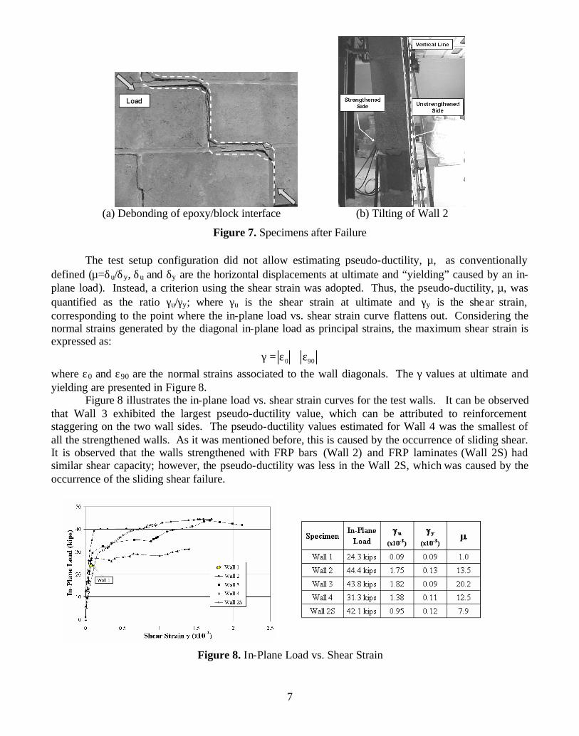
The test setup configuration did not allow estimating pseudo-ductility, µ, as conventionally defined (µ=δu/δy, δu and δy are the horizontal displacements at ultimate and “yielding” caused by an in-plane load). Instead, a criterion using the shear strain was adopted. Thus, the pseudo-ductility, µ, was quantified as the ratio γu/γy; where γu is the shear strain at ultimate and γy is the shear strain, corresponding to the point where the in-plane load vs. shear strain curve flattens out. Considering the normal strains generated by the diagonal in-plane load as principal strains, the maximum shear strain is expressed as:
0 90γ = ε + ε where ε0 and ε90 are the normal strains associated to the wall diagonals. The γ values at ultimate and yielding are presented in Figure 8.
Figure 8 illustrates the in-plane load vs. shear strain curves for the test walls. It can be observed that Wall 3 exhibited the largest pseudo-ductility value, which can be attributed to reinforcement staggering on the two wall sides. The pseudo-ductility values estimated for Wall 4 was the smallest of all the strengthened walls. As it was mentioned before, this is caused by the occurrence of sliding shear. It is observed that the walls strengthened with FRP bars (Wall 2) and FRP laminates (Wall 2S) had similar shear capacity; however, the pseudo-ductility was less in the Wall 2S, which was caused by the occurrence of the sliding shear failure.
Figure 8. In-Plane Load vs. Shear Strain
8
Anchorage Improvement
The following experimental program dealt with the retrofitting of masonry walls exhibiting anchorage deficiencies. To be effective, FRP shear strengthening depends on the development of the wall flexural capacity, which in turns relies on the anchorage of the existing steel reinforcement. Experimental Program
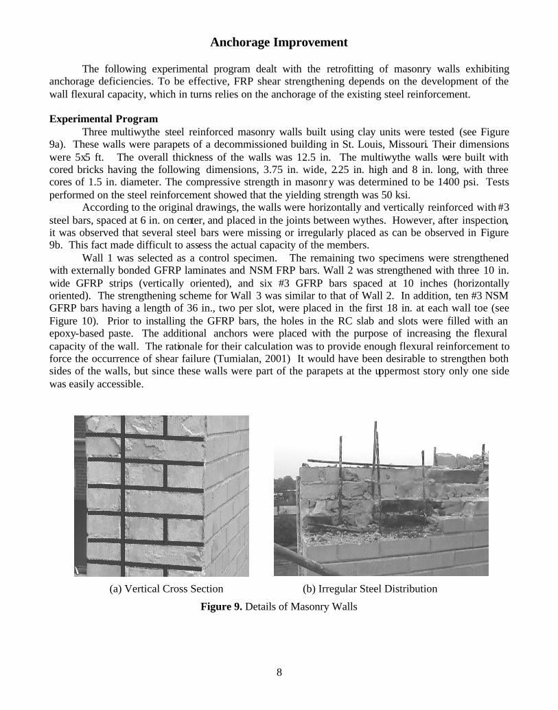
Three multiwythe steel reinforced masonry walls built using clay units were tested (see Figure 9a). These walls were parapets of a decommissioned building in St. Louis, Missouri. Their dimensions were 5x5 ft. The overall thickness of the walls was 12.5 in. The multiwythe walls were built with cored bricks having the following dimensions, 3.75 in. wide, 2.25 in. high and 8 in. long, with three cores of 1.5 in. diameter. The compressive strength in masonry was determined to be 1400 psi. Tests performed on the steel reinforcement showed that the yielding strength was 50 ksi.
According to the original drawings, the walls were horizontally and vertically reinforced with #3 steel bars, spaced at 6 in. on center, and placed in the joints between wythes. However, after inspection, it was observed that several steel bars were missing or irregularly placed as can be observed in Figure 9b. This fact made difficult to assess the actual capacity of the members.
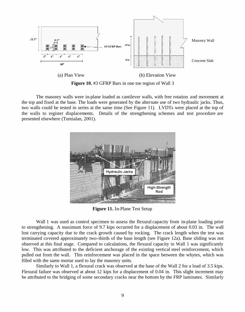
Wall 1 was selected as a control specimen. The remaining two specimens were strengthened with externally bonded GFRP laminates and NSM FRP bars. Wall 2 was strengthened with three 10 in. wide GFRP strips (vertically oriented), and six #3 GFRP bars spaced at 10 inches (horizontally oriented). The strengthening scheme for Wall 3 was similar to that of Wall 2. In addition, ten #3 NSM GFRP bars having a length of 36 in., two per slot, were placed in the first 18 in. at each wall toe (see Figure 10). Prior to installing the GFRP bars, the holes in the RC slab and slots were filled with an epoxy-based paste. The additional anchors were placed with the purpose of increasing the flexural capacity of the wall. The rationale for their calculation was to provide enough flexural reinforcement to force the occurrence of shear failure (Tumialan, 2001) It would have been desirable to strengthen both sides of the walls, but since these walls were part of the parapets at the uppermost story only one side was easily accessible.
(a) Vertical Cross Section (b) Irregular Steel Distribution
Figure 9. Details of Masonry Walls
9
0.5”
1” #3 GFRP Bars
18”
0.5”
1” #3 GFRP Bars
18”
Masonry Wall
Concrete Slab
(a) Plan View (b) Elevation View
Figure 10. #3 GFRP Bars in one toe region of Wall 3
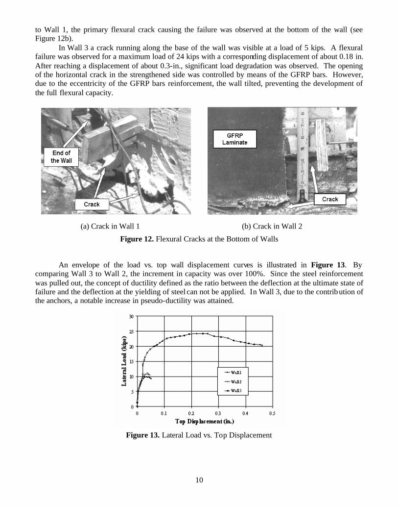
The masonry walls were in-plane loaded as cantilever walls, with free rotation and movement at
the top and fixed at the base. The loads were generated by the alternate use of two hydraulic jacks. Thus, two walls could be tested in series at the same time (See Figure 11). LVDTs were placed at the top of the walls to register displacements. Details of the strengthening schemes and test procedure are presented elsewhere (Tumialan, 2001).
Figure 11. In-Plane Test Setup
Wall 1 was used as control specimen to assess the flexural capacity from in-plane loading prior
to strengthening. A maximum force of 9.7 kips occurred for a displacement of about 0.03 in. The wall lost carrying capacity due to the crack growth caused by rocking. The crack length when the test was terminated covered approximately two-thirds of the base length (see Figure 12a). Base sliding was not observed at this final stage. Compared to calculations, the flexural capacity in Wall 1 was significantly low. This was attributed to the deficient anchorage of the existing vertical steel reinforcement, which pulled out from the wall. This reinforcement was placed in the space between the whytes, which was filled with the same mortar used to lay the masonry units.
Similarly to Wall 1, a flexural crack was observed at the base of the Wall 2 for a load of 3.5 kips. Flexural failure was observed at about 12 kips for a displacement of 0.04 in. This slight increment may be attributed to the bridging of some secondary cracks near the bottom by the FRP laminates. Similarly
10
to Wall 1, the primary flexural crack causing the failure was observed at the bottom of the wall (see Figure 12b).
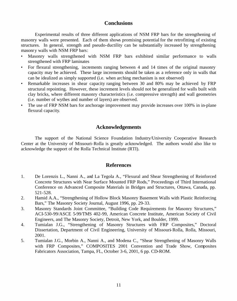
In Wall 3 a crack running along the base of the wall was visible at a load of 5 kips. A flexural failure was observed for a maximum load of 24 kips with a corresponding displacement of about 0.18 in. After reaching a displacement of about 0.3-in., significant load degradation was observed. The opening of the horizontal crack in the strengthened side was controlled by means of the GFRP bars. However, due to the eccentricity of the GFRP bars reinforcement, the wall tilted, preventing the development of the full flexural capacity.
(a) Crack in Wall 1 (b) Crack in Wall 2
Figure 12. Flexural Cracks at the Bottom of Walls
An envelope of the load vs. top wall displacement curves is illustrated in Figure 13. By comparing Wall 3 to Wall 2, the increment in capacity was over 100%. Since the steel reinforcement was pulled out, the concept of ductility defined as the ratio between the deflection at the ultimate state of failure and the deflection at the yielding of steel can not be applied. In Wall 3, due to the contribution of the anchors, a notable increase in pseudo-ductility was attained.
Figure 13. Lateral Load vs. Top Displacement
11
Conclusions
Experimental results of three different applications of NSM FRP bars for the strengthening of
masonry walls were presented. Each of them shows promising potential for the retrofitting of existing structures. In general, strength and pseudo-ductility can be substantially increased by strengthening masonry walls with NSM FRP bars: • Masonry walls strengthened with NSM FRP bars exhibited similar performance to walls
strengthened with FRP laminates • For flexural strengthening, increments ranging between 4 and 14 times of the original masonry
capacity may be achieved. These large increments should be taken as a reference only in walls that can be idealized as simply supported (i.e. when arching mechanism is not observed)
• Remarkable increases in shear capacity ranging between 30 and 80% may be achieved by FRP structural repointing. However, these increment levels should not be generalized for walls built with clay bricks, where different masonry characteristics (i.e. compressive strength) and wall geometries (i.e. number of wythes and number of layers) are observed.
• The use of FRP NSM bars for anchorage improvement may provide increases over 100% in in-plane flexural capacity.
Acknowledgements
The support of the National Science Foundation Industry/University Cooperative Research Center at the University of Missouri–Rolla is greatly acknowledged. The authors would also like to acknowledge the support of the Rolla Technical Institute (RTI).
References 1. De Lorenzis L., Nanni A., and La Tegola A., “Flexural and Shear Strengthening of Reinforced
Concrete Structures with Near Surface Mounted FRP Rods,” Proceedings of Third International Conference on Advanced Composite Materials in Bridges and Structures, Ottawa, Canada, pp. 521-528.
2. Hamid A.A., “Strengthening of Hollow Block Masonry Basement Walls with Plastic Reinforcing Bars,” The Masonry Society Journal, August 1996, pp. 29-33.
3. Masonry Standards Joint Committee, “Building Code Requirements for Masonry Structures,” ACI-530-99/ASCE 5-99/TMS 402-99, American Concrete Institute, American Society of Civil Engineers, and The Masonry Society, Detroit, New York, and Boulder, 1999.
4. Tumialan J.G., “Strengthening of Masonry Structures with FRP Composites,” Doctoral Dissertation, Department of Civil Engineering, University of Missouri-Rolla, Rolla, Missouri, 2001.
5. Tumialan J.G., Morbin A., Nanni A., and Modena C., “Shear Strengthening of Masonry Walls with FRP Composites,” COMPOSITES 2001 Convention and Trade Show, Composites Fabricators Association, Tampa, FL, October 3-6, 2001, 6 pp. CD-ROM.