Embed Size (px)
Citation preview
Strengthening steel bridges with new high modulus CFRP materials
M. Dawood, E. Sumner & S. Rizkalla North Carolina State University Raleigh, North Carolina, U.S.A .
D. Schnerch, Wiss, Janney, Elstner Associates, Inc. Cambridge, Massachusetts, U.S.A.
1 EXTENDED ABSTRACT
Due to corrosion and the continuous demand to increase traffic loads, there is a need for an efficient, cost-effective system which can be used for the repair and strengthening of steel highway bridge girders. Research has been conducted to investigate the use of carbon fiber reinforced polymer (CFRP) materials to address this need and the effectiveness of the technique for repair and strengthening of steel and steel-concrete composite bridge girders has been demonstrated. However, the majority of the previous research has focused on the use of conventional modulus CFRP materials for the repair and strengthening of steel bridge members. While substantial strength increases have been achieved, typically large amounts of strengthening are required to achieve a comparable increase of the elastic stiffness. This is due to the relatively low modulus of elasticity of the CFRP as compared to steel and also possibly due to the presence of shear-lag effects between the steel beam and the CFRP materials.
Recently, high modulus CFRP (HM CFRP) materials have become commercially available which have a modulus of elasticity approximately twice that of conventional steel. This paper presents the details and relevant findings of an experimental investigation which was conducted to investigate the behavior of a new HM CFRP system which can be used for the strengthening and repair of steel bridges. Additional details about the research program are available in Schncerch (2005) and Dawood (2005). Design guidelines are also presented which can be used for the design and analysis of steel-concrete composite girders strengthened with HM CFRP.
2 HM CFRP STRENGTHENING SYSTEM
Two types of unidirectional, pultruded CFRP laminates were used in the experimental program. The first laminate used an intermediate modulus carbon fiber (440 GPa), DIALEAD K63312, which is produced by Mitsubishi Chemical Functional Products, Inc. The second laminate used the higher modulus (640 GPa) DIALEAD K637l2 carbon fibers. The CFRP laminates were bonded to the tension flange of the steel beams using a two part epoxy adhesive.
3 EXPERJMENTAL PROGRAM
The experimental program was conducted in three phases to establish the feasibility of various HM CFRP strengthening systems and to investigate the fundamental behavior of steelconcrete composite beams strengthened with HM CFRP materials. The first phase consisted of three beams that were tested to investigate the feasibility of three different configurations of CFRP strengthening systems. Two of the beams were strengthened with high modulus and intermediate modulus (IM) CFRP materials respectively while the third beam was strengthened
with prestressed lIM CFRP strips. In the second phase, a total of three beams were tested to investigate the behavior under overloading conditions. The third phase was designed to study the fatigue durability of the strengthening system. Two of these beams were strengthened with lIM CFRP materials, while the third beam remained unstrengthened as a control beam for the fatigue study. All of the beams were tested in a four point bending configuration.
4 EXPERIMENTAL RESULTS
The results of the experimental program demonstrate that both the intermediate-modulus and the high-modulus strengthening systems resulted in a significant increase of the elastic stiffness and the ultimate capacity of the strengthened beams. Alternatively, the prestressed beam was designed to provide the maximum stiffness increase, without increasing the ultimate strength of the section. The use of the prestressed laminates helped to improve the efficiency of utilization of the strengthening system by reducing the amount of strengthening required to obtain a comparable increase in the elastic stiffness. The results of the overloading study further demonstrated that beams strengthened with lIM CFRP materials exhibit lower residual deflections in the event of overloading conditions as compared to an unstrengthened beam. The presence of the lIM CFRP also helped to reduce the stress in the tension flange of the steel beam, thereby increasing the yield load of the strengthened beams. The two strengthened beams that were tested in the fatigue study survived three million fatigue loading cycles with an increase of the load range of 20 percent as compared to an unstrengthened control beam. The improved performance of the strengthened beams indicates that it may be possible to increase the allowable live load level of a steel-concrete composite girder strengthened with lIM CFRP materials.
5 PROPOSED DESIGN GUIDELINES
Based on the findings of this research program design guidelines have been developed which can be used by practitioners to design lIM CFRP strengthening systems for steel-concrete composite beams. The design guidelines are based on a non-linear moment-curvature analysis which satisfies the conditions of equilibrium and compatibility. The guidelines follow the design philosophies presented in ACI 440.2R-02, but have been adopted for application to steel bridges.
Based on the' moment-curvature analysis, the allowable increase of live load for a strengthened steel-concrete composite beam should be selected to satisfy three conditions. The three conditions which are proposed were selected to ensure the safety of the strengthened beam under ultimate loading conditions, maintain the fatigue durability of the strengthened bridge girders and prevent catastrophic failure in the event of unexpected loss of the strengthening system.
6 CONCLUSIONS
The findings of this research demonstrate that lIM CFRP materials can be effectively used for the repair and strengthening of steel-concrete composite bridge girders. Based on these findings, a simplified design procedure was established to facilitate the safe design and analysis of steelconcrete composite bridge girders strengthened with lIM CFRP materials. This program demonstrates that the use of lIM CFRP materials represents an efficient, cost-effective alternative for repair and strengthening of steel bridges.
REFERENCES
Dawood, M. (2005). Fundamental Behavior of Steel-Concrete Composite Beams Strengthened with High Modulus Carbon Fiber Reinforced Polymer (CFRP) Materials. Master's Thesis, North Carolina State University, Raleigh, North Carolina.
Schnerch, D. (2005). Strengthening of steel structures with high modulus carbon fiber reinforcedpolymer (CFRP) Materials. Ph.D. dissertation, North Carolina State University, Raleigh, North Carolina.
Strengthening steel bridges with new high modulus CFRP materials
M. Dawood, E. Sumner & S. Rizkalla North Carolina State University Raleigh, North Carolina, U.S.A.
D. Schnerch, Wiss, Janney, Elstner Associates, Inc. Cambridge, Massachusetts, U.S.A.
ABSTRACT: This paper presents the details and relevant findings of an experimental program which was conducted in three phases to investigate the behavior of steel-concrete composite bridge girders strengthened with new high modulus carbon fiber reinforced polymer (HM CFRP) materials. In the first phase, the feasibility of various lIM CFRP strengthening systems was examined. The second phase investigated the behavior of the strengthened beams under overloading conditions. The fatigue durability of the strengthening system was investigated in the third phase. Based on the findings of the experimental program, simplified design guidelines are presented for the design and analysis of steel-concrete composite bridge girders strengthened with lIM CFRP materials.
I INTRODUCTION
Due to corrosion and the continuous demand to increase traffic loads, there is a need for an efficient, cost-effective system which can be used for the repair and strengthening of steel highway bridge girders. Recently, research has been conducted to investigate the use of carbon fiber reinforced polymer (CFRP) materials to address this need. CFRP materials have been used to repair naturally deteriorated steel bridge girders (Mertz & Gillespie, 1996) and artificially damaged steel-concrete composite girders (Tavakkolizadeh and Saadatrnanesh, 2003b, AI-Saidy et aI., 2005). The previous research demonstrates that this technique can restore the elastic stiffness and the ultimate capacity of the deteriorated members to levels comparable to that of the undamaged girder. CFRP laminates have also been used for the repair of overloaded steel-concrete composite beams (Sen et aI., 2001). The presence of the CFRP strips increased the yield load and ultimate capacity of the repaired beams by up to 67 percent and 52 percent respectively. The effectiveness of using CFRP materials for strengthening of undamaged steel-concrete composite beams has also been investigated (Tavakkolizadeh and Saadatrnanesh, 2003c). The use of externally bonded CFRP materials increased the ultimate capacity of the strengthened girders and additionally helped to reduce residual deflections due to the effect of overloading conditions.
Studies on the fatigue durability of steel beams strengthened with CFRP materials have been limited. Externally bonded CFRP patches can be used to reduce crack propagation rates and increase the fatigue life of cracked steel members (Tavakkolizadeh and Saadatrnanesh 2003a). In another study, the fatigue durability of externally bonded CFRP materials which were used to repair naturally deteriorated steel bridge girders was found to be comparable to that of conventional steel details which are commonly used in steel bridge construction (Miller et aI., 2001).
The majority of the previous research has focused on the use of conventional modulus CFRP materials for the repair and strengthening of steel bridge members . While substantial strength increases have been achieved, typically large amounts of strengthening are required to achieve a comparable increase of the elastic stiffness. This is due to the relatively low modulus of elasticity of the CFRP as compared to steel and also possibly due to the presence of shear-lag effects between the steel beam and the CFRP materials (Tavakkolizadeh and Saadatrnanesh, 2003c).
Recently, high modulus CFRP (HM CFRP) materials have become commercially available which have a modulus of elasticity approximately twice that of conventional steel. This paper presents the details and relevant [mdings of an experimental investigation which was conducted to investigate the behavior of a new HM CFRP system which can be used for the strengthening and repair of steel bridges. Additional details about the research program are available in Schncerch (2005) and Dawood (2005). Design guidelines are also presented which can be used for the design and analysis of steel-concrete composite girders strengthened with HM CFRP.
2 HM CFRP STRENGTHENING SYSTEM
Two types of unidirectional, pultruded CFRP laminates were used in the experimental program. The first laminate, designated DC-I, was produced by Diversified Composites using an intermediate modulus carbon fiber (440 GPa), DIALEAD K63312, which is produced by Mitsubishi Chemical Functional Products, Inc. The second laminate, designated THM-4S0, was manufactured by Epsilon Composite using the higher modulus (640 GPa) DIALEAD K63712. The material properties of the two laminates, as reported by their respective manufacturers, are presented in Table 1. The values given for the THM-450 laminates are the average of test results for the same laminates pultruded to two different thicknesses.
Table I. Properties for the two types of CFRP laminates used in the experimental program CFRP Laminate Thickness Tensile Strength Tensile Modulus Ultimate Strain
(mm) (MPa) (MPa) (mm/mm) DC-I 3.2 1224 229 0.0051 THM-450 2.9 or 4.0 1534 457 0.0033
The CFRP laminates were bonded to the tension flange of the steel beams using the Spabond 345 two part epoxy adhesive with the fast hardener produced by SP Systems North America. The tension flange of the steel beam was grit blasted to 'white metal' immediately prior to installation of the strengthening. The surface was subsequently cleaned by air blowing and solvent wiping. The CFRP strips were installed and a clamping system was applied for 12 hours until the adhesive had thoroughly set. The adhesive was allowed to cure for one week prior to testing.
3 EXPE~NTALPROGRAJd
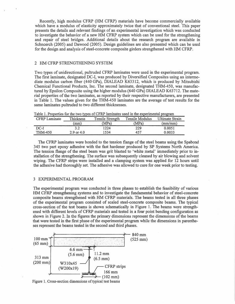
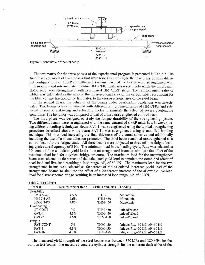
The experimental program was conducted in three phases to establish the feasibility of various HM CFRP strengthening systems and to investigate the fundamental behavior of steel-concrete composite beams strengthened with HM CFRP materials. The beams tested in all three phases of the experimental program consisted of scaled steel-concrete composite beams. The typical cross-section of the test beams is shown schematically in Figure I. The beams were strengthened with different levels of CFRP materials and tested in a four point bending configuration as shown in Figure 2. In the figures the primary dimensions represent the dimensions of the beams that were tested in the first phase of the experimental program while the dimensions in parentheses represent the beams tested in the second and third phases.
+~'==================j1:-' 840mtu 100 mm -,f I I (525 mm) (65 mm)+l __ --:-:--~ __ of--------'
313 mm (200 mm)
6.6 mm ~ J--1 (5.6mm) 11.2mm
/ (6.5 mm) W310x45 ---'
(W200xI9) CFRP strips 166mm
~;--') (102 mm) Figure I. Cross-section dimensions of typical test beams
hydraulic actuato
2700 mm
1 (1219 mm)-"'~-"~~~r'--"""""-'Ii-~"" preader beam neoprene pad
Test beam
pin support 0 neoprene pad
. ' oller support or
neoprene pad 1000 mm (610 mm) 6400 mm
>------------('3050 mm)-----------I
Figure 2. Schematic of the test setup
The test matrix for the three phases of the experimental program is presented in Table 2. The first phase consisted of three beams that were tested to investigate the feasibility of three different configurations of CFRP strengthening systems, Two of the beams were strengthened with high modulus and intermediate modulus (IM) CFRP materials respectively while the third beam, HM-3.8-PS, was strengthened with prestressed HM CFRP strips. The reinforcement ratio of CFRP was calculated as the ratio of the cross-sectional area of the carbon fiber, accounting for the fiber volume fraction of the laminates, to the cross-sectional area of the steel beam.
In the second phase, the behavior of the beams under overloading conditions was investigated. Two beams were strengthened with different reinforcement ratios of HM CFRP and subjected to several unloading and reloading cycles to simulate the effect of severe overloading conditions. The behavior was compared to that of a third unstrengthened control beam.
The third phase was designed to study the fatigue durability of the strengthening system. Two different beams were strengthened with the same amount of CFRP materials, however, using different bonding techniques. Beam FAT-l was strengthened using the typical strengthening procedure described above while beam FAT-lb was strengthened using a modified bonding technique. This involved increasing the final thickness of the cured adhesive and additionally including the use of a silane adhesion promoter. The third beam remained unstrengthened as a control beam for the fatigue study. AIl three beams were subjected to three million fatigue loading cycles at a frequency of 3 Hz. The minimum load in the loading cycle, P min, was selected as 30 percent of the calculated yield load of the unstrengthened beams to simulate the effect of the sustained dead-load for a typical bridge structure. The maximum load for the unstrengthened beam was selected as 60 percent of the calculated yield load to simulate the combined effect of dead-load and live-load resulting a load range, 6.P, of 50 kN. The maximum load for the two strengthened beams was selected as 60 percent of the calculated increased yield load of the strengthened beams to simulate the effect of a 20 percent increase of the allowable live-load level for a strengthened bridge resulting in an increased load range, 6.P, of 60 kN.
Table 2. Test Matrix BeamID Reinforcement Ratio CFRP Laminates Loadin!\ Feasibility
IM-4.5-AB 4.5% CP-I Monotonic HM-7.6-AB 7.6% THM-450 Monotonic HM-3 .8-PS 3.8% THM-450 Monotonic
Overloading ST-CONT 0% THM-450 unload/reload OVL- l 4.3% THM-450 unload/niload OVL-2 8.6% THM-450 unload/reload
Fatigue FAT-CONT 0% THM-450 fatigue: Pmin~50 kN, CJ>~50 kN FAT-l 4.3% THM-450 fatigue: Pmin~50 kN, t.P~60 kN FAT- lb 4.3% THM-450 fati!l!!e: P min~50 kN, t.P~60 kN
The measured yield strength of the steel beams was between 370 MPa and 380 MPa for the various test beams. The measured concrete cylinder strength for the concrete deck slabs of the
different test beams ranged between 34 MPa and 58 MPa at the time of testing. All of the test beams were instrumented to measure deflections at midspan and at the supports as well as to measure strains at various locations along the midspan cross-section of the beam.
4 EXPERIMENTAL RESULTS
This section presents the results of each of the three phases of the experimental program and discusses the relevant research findings. The three phases of the experimental program are presented separately in the following sections.
4.1 Findings ofthefeasibilitystudy
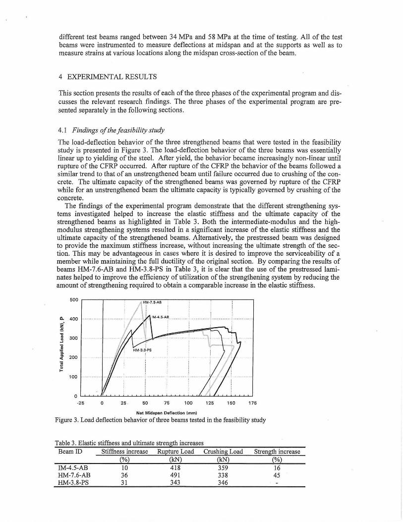
The load-deflection behavior of the three strengthened beams that were tested in the feasibility study is presented in Figure 3. The load-deflection behavior of the three beams was essentially linear up to yielding of the steel. After yield, the behavior became increasingly non-linear until rupture of the CFRP occurred. After rupture of the CFRP the behavior of the beams followed a similar trend to that of an unstrengthened beam until failure occurred due to crushing of the concrete. The ultimate capacity of the strengthened beams was governed by rupture of the CFRP while for an unstrengthened beam the ultimate capacity is typically governed by crushing of the concrete.
The findings of the experimental program demonstrate that the different strengthening systems investigated helped to increase the elastic stiffness and the ultimate capacity of the strengthened beams as highlighted in Table 3. Both the intermediate-modulus and the highmodulus strengthening systems resulted in a significant increase of the elastic stiffness and the ultimate capacity of the strengthened beams. Alternatively, the prestressed beam was designed to provide the maximum stiffness increase, without increasing the ultimate strength of the section. This may be advantageous in cases where it is desired to improve the serviceability of a member while maintaining the full ductility of the original section. By comparing the results of beams HM-7.6-AB and HM-3.8-PS in Table 3, it is clear that the use of the prestressed laminates helped to improve the efficiency of utilization of the strengthening system by reducing the amount of strengthening required to obtain a comparable increase in the elastic stiffness.
500
0.. 400 ........ 1 ...... .
Z
'" ~ • 300 0 ~
~ • ~ ~ 200 " .. 0 I-
100 ._ ... _ ... ,,_ .. " .. " ..•.. _._ .•.•. _. _ .•. __ .... , ... ,
0
·25 0 25 50 75 100 125 150 175
Net Midspan Deflection {mm)
Figure 3. Load deflection behavior of three beams tested in the feasibility study
Table 3. Elastic stiffness and ultimate strength increases Beam ID
IM-4.5-AB HM-7.6-AB HM-3.8-PS
Stiffness increase (%) 10 36 31
Rupture Load (kN) 418 491 343
Crushing Load (kN) 359 338 346
Strength increase (%) 16 45
4.2 Findings of the overloading study
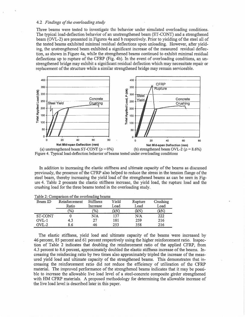
Three beams were tested to investigate the behavior under simulated overloading conditions. The typical load-deflection behavior of an unstrengthened beam (ST-CONT) and a strengthened beam (OVL-2) are presented in Figures 4a and b respectively. Prior to yielding of the steel all of the tested beams exhibited minimal residual deflections upon unloading. However, after yielding, the unstrengthened beam exhibited a significant increase of the measured residual deflection, as shown in Figure 4a, while the strengthened beams continued to exhibit minimal residual deflections up to rupture of the CFRP (Fig. 4b). In the event of overloading conditions, an unstrengthened bridge may exhibit a significant residual deflection which may necessitate repair or replacement of the structure while a similar strengthened bridge may remain serviceable.
400
350
z =- 300
'll .3 250 'C
~200 c. c. « 150
.... ~ 100
50
o
Steel Yield I
V /f' 1/ I II
II I
o 20
Concrete Crushjng
40 60 80
400 +===============1 • CFRP
~350t-----/~~"K~lUP~X~lur~e~----------~
;;:- 300 :;teel./'- I-------------------1 .,; Yield Concrete S 250, Crushing
]! 200 J-~J_---'b.-~=======3...:::..-_l :150t-~--~~7----------------~ ~ ~ 100~1-_.~----------------~
50-ll-- h-H--------l 0~~U-~----__ ----__ ----~
o 20 40 60 80
Net Mid~span Deflection (Ilm) Net Mid-span Deflection (mm)
Ca) unstrengthened beam ST-CONT Cp = 0%) Cb) strengthened beam OVL-2 Cp = 8.6%) Figure 4. Typical load-deflection behavior of beams tested under overloading conditions
In addition to increasing the elastic stiffness and ultimate capacity of the beams as discussed previously, the presence of the CFRP also helped to reduce the stress in the tension flange of the steel beam, thereby increasing the yield load of the strengthened beams as can be seen in Figure 4. Table 2 presents the elastic stiffness increase, the yield load, the rupture load and the crushing load for the three beams tested in the overloading study.
Table 2: ComEarison of the overloadin!l beams BeamID Reinforcement Stiffness Yield Rupture Crushing
Ratio Increase Load Load Load (%) (%) ~ (kN) (kN)
ST-CONT 0 N/A 137 N/A 222 OVL-I 4.3 27 181 259 216 OVL-2 8.6 46 253 358 216
The elastic stiffness, yield load and ultimate capacity of the beams were increased by 46 percent, 85 percent and 61 percent respectively using the higher reinforcement ratio. Inspection of Table 2 indicates that doubling the reinforcement ratio of the applied CFRP, from 4.3 percent to 8.6 percent, approximately doubled the elastic stiffness increase of the beams. Increasing the reinforcing ratio by two times also approximately tripled the increase of the measured yield load and ultimate capacity of the strengthened beams. This demonstrates that increasing the reinforcement ratio did not reduce the efficiency of utilization of the CFRP material. The improved performance of the strengthened beams indicates that it may be possible to increase the allowable live load level of a steel-concrete composite girder strengthened with HM CFRP materials . A proposed methodology for determining the allowable increase of the live load level is described later in this paper.
4.3 Findings of the fatigue study
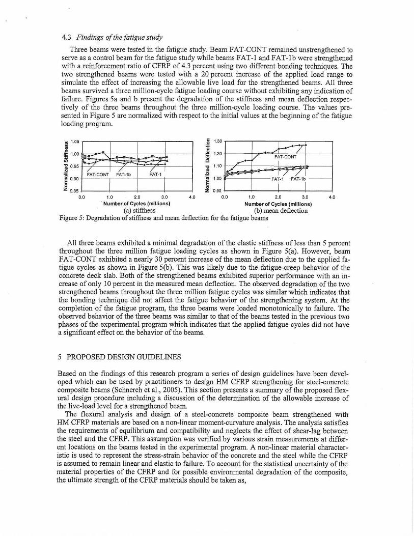
Three beams were tested in the fatigue study. Beam FAT -CONT remained unstrengthened to serve as a control beam for the fatigue study while beams FAT-I and FAT-Ib were strengthened with a reinforcement ratio of CFRP of 4.3 percent using two different bonding techniques. The two strengthened beams were tested with a 20 percent increase of the applied load range to simulate the effect of increasing the allowable live load for the strengthened beams. All three beams survived a three million-cycle fatigue loading course without exhibiting any indication of failure. Figures 5a and b present the degradation of the stiffness and mean deflection respectively of the three beams throughout the three million-cycle loading course. The values presented in Figure 5 are normalized with respect to the initial values at the beginning of the fatigue loading program.
' 11) 1.05 ~--~--~---~--~
~ ~ 1.00
m ~~~=t~~~~~~~--J a: 0.95 ~ .!::l FAT-CONT FAT-1b FAT-1 ~ 0.90 J-..:.:.::....:=..,-.:~~+---'..:."--'-+----l o Z 0.85 +----I-----l---+----I
.2 1.30
~ '.20
't:I 1.10
.§ ~ 1.00
o Z 0.90
)-..... -y ...... - V FAT-CONT
I
~o='I=i= ~--,,-Ij -~ FAt·' FAT.', 0.0 1.0 2.0 3.0 4.0 0.0 1.0 2,0 3.0
. Number of Cycles (millions) Number of Cycles (millions) (a) stiffuess (b) mean deflection
Figure 5: Degradation of stiffuess and mean deflection for the fatigue beams
4.0
All three beams exhibited a minimal degradation of the elastic stiffuess of less than 5 percent throughout the three million fatigue loading cycles as shown in Figure 5(a). However, beam FAT-CONT exhibited a nearly 30 percent increase of the mean deflection due to the applied fatigue cycles as shown in Figure 5(b). This was likely due to the fatigue-creep behavior of the concrete deck slab. Both of the strengthened beams exhibited superior performance with an increase of only 10 percent in the measured mean deflection. The observed degradation of the two strengthened beams throughout the three million fatigue cycles was similar which indicates that the bonding technique did not affect the fatigue behavior of the strengthening system. At the completion of the fatigue program, the three beams were loaded monotonically to failure. The observed behavior of the three beams was similar to that of the beams tested in the previous two phases of the experimental program which indicates that the applied fatigue cycles did not have a significant effect on the behavior of the beams.
5 PROPOSED DESIGN GUIDELINES
Based on the findings of this research program a series of design guidelines have been developed which can be used by practitioners to design HM CFRP strengthening for steel-concrete composite beams (Schnerch et a!., 2005). This section presents a summary of the proposed flexural design procedure including a discussion of the determination of the allowable increase of the live-load level for a strengthened beam.
The flexural analysis and design of a steel-concrete composite beam strengthened with HM CFRP materials are based on a non-linear moment-curvature analysis. The analysis satisfies the requirements of equilibrium and compatibility and neglects the effect of shear-lag between the steel and the CFRP. This assumption was verified by various strain measurements at different locations on the beams tested in the experimental program. A non-linear material characteristic is used to represent the stress-strain behavior of the concrete and the steel while the CFRP is assumed to remain linear and elastic to failure. To account for the statistical uncertainty of the material properties of the CFRP and for possible environmental degradation of the composite, the ultimate strength of the CFRP materials should be taken as,
(I)
where iFRP,u is the design strength of the :tRP materials, CE is the environmental degradation factor (typically taken as 0,85 for CFRP) IFRP u is the mean strength of the FRP reported by the manufacturer and cr is the reported standard deviation of the FRP strength (ACI 440,2R-02, 2002). The average modulus of elasticity of the CFRP reported by the manufacturer should be used in the analysis to accurately represent the behavior of the strengthened girder, The design rupture strain of the CFRP can then be calculated using the design rupture strength and modulus of elasticity of the composite,
The nominal moment-curvature behavior of the strengthened section can be established by incrementally increasing the strain at the top surface of the concrete deck and iterating the neutral axis depth until horizontal force equilibrium is satisfied, The nominal moment capacity of the strengthened section, Mn,s, will typically occur when the strain at the level of the CFRP reaches the design rupture strain of the material. The design ultimate capacity of the strengthened beam, Mu,s should be calculated as <l>Mn,s . To account for the brittle nature of failure, a strength reduction factor, <1>, of 0.75 is recommended for rupture type limit states (AISC LFRD Specification, 2001), After rupture of the CFRP, the analysis is similar to that of an unstrengthened steel-concrete composite beam until the crushing strain of the concrete is reached,
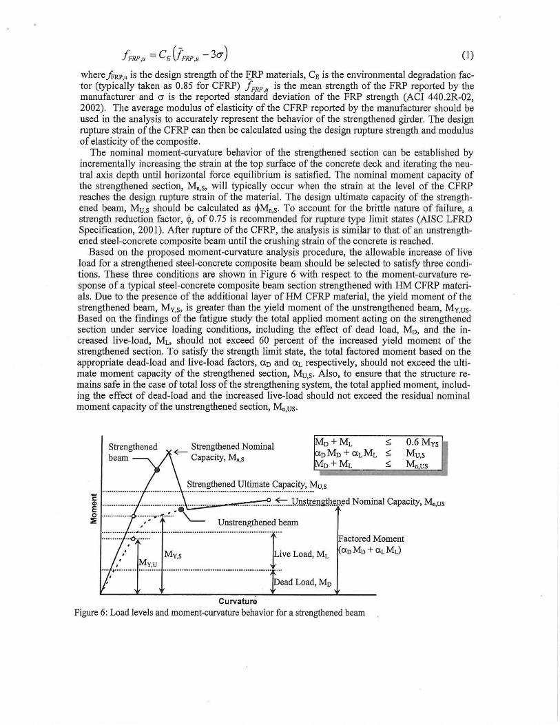
Based on the proposed moment-curvature analysis procedure, the allowable increase of live load for a strengthened steel-concrete composite beam should be selected to satisfy three conditions, These three conditions are shown in Figure 6 with respect to the moment-curvature response of a typical steel-concrete composite beam section strengthened with HM CFRP materials. Due to the presence of the additional layer of HM CFRP material, the yield moment of the strengthened beam, My,s, is greater than the yield moment of the unstrengthened beam, My,us, Based on the findings of the fatigue study the total applied moment acting on the strengthened section under service loading conditions, including the effect of dead load, Mo, and the increased live-load, ML, should not exceed 60 percent of the increased yield moment of the strengthened section, To satisfy the strength limit state, the total factored moment based on the appropriate dead-load and live-load factors, aD and aL respectively, should not exceed the ultimate moment capacity of the strengthened section, Mu,s, Also, to ensure that the structure remains safe in the case of total loss of the strengthening system, the total applied moment, including the effect of dead-load and the increased live-load should not exceed the residual nominal moment capacity of the unstrengthened section, Mn,us,
Strengthened Nominal <E---- C . apaClty, M~s
0+ ML ,; oMo +aLML ,; 0+ ML ,;
" .... " .................................. ~~ ... n.~h.".n.".~ylt.u.?~t.e .. <::~p.~.~.i~:,~u,s
O.6Mys Mu,s Mnus
..................... ~ .. y.!J.~.tr,~l!g!l!&".ed Nominal Capacity, Mn,us
Unstrengthened beam :::::::::::.,:-:(,..:::::: ........... , ................. , .......... , .. , .......... , .. ' .... · .. r .. .. ,
/ My s ive Load, ML ,# My,u .
.... ) ....................... - ................... , ...... , ....... " .................. " ...... .
Dead Load, MD
Curvature
actored Moment CloMo + ClLML)
Figure 6: Load levels and moment-curvature behavior for a strengthened beam
6 CONCLUSIONS
The findings of this research demonstrate that HM CFRP materials can be effectively used for the repair and strengthening of steel-concrete composite bridge girders. The experimental program demonstrated the feasibility of using various configurations of high and intermediate modulus CFRP materials to increase the elastic stiffness, yield load and ultimate capacity of steel-concrete composite beams. The presence of the CFRP can also help to reduce the residual deflection due to overloading conditions. The fatigue durability of the strengthened beams is comparable to that of an unstrengthened steel beam provided that the maximum applied moment, due to the combined effect of dead load and live load, does not exceed 60 percent of the increased yield moment of the strengthened section. Based on the findings of this research, a simplified design procedure was established to facilitate the safe design and analysis of steelconcrete composite bridge girders strengthened with HM CFRP materials. This research demonstrates that the use of HM CFRP materials represents an efficient, cost-effective alternative for repair and strengthening of steel bridges .
ACKNOWLEDGEMENTS
The authors would like to acknowledge the support provided by the National Science Foundation (NSF) IndustrylUniversity Cooperative Research Center (I/UCRC) for the Repair of Buildings and Bridges with Composites (RB'C) and the support provided by Mitsubishi Chemical FP America Inc.
REFERENCES
AI-Saidy, A.H., Klaiber, F.W. & Wipf, T.J. (2004). Repair of steel composite beams with carbon fiberreinforced polymer plates. Journal of Composites for Construction, 8 (2), 163-172.
American Concrete Institute. (2002). A CI 440.2R-02 Guide for the design and construction of externally bonded FRP systems for strengthening concrete structures.
American Institute of Steel Construction. (2001). Manual of steel construction: load and resistancefactor design. Third edition.
Dawood, M. (2005). Fundamental Behavior of Steel-Concrete Composite Beams Strengthened with High Modulus Carbon Fiber Reinforced Polymer (CFRP) Materials. Master's Thesis, North Carolio. State University, Raleigh, North Carolioa.
Mertz, D.R. & Gillespie Jr., J. W. (1996). Rehabilitation of steel bridge girders through the application of advanced composite materials (Contract NCHRP-93-IDOll). Washiogton, D.e.: Transportation Research Board.
Miller, T.e., Chajes, M.J., Mertz, D.R. & Hastings, J.N. (2001). Strengtheniog of a steel bridge girder usiog CFRP plates. Journal of Bridge Engineering, 6 (6),514-522.
Schnerch, D. (2005). Strengthening of steel structures with high modulus carbon fiber reinforced polymer (CFRP) Materials. Ph.D. dissertation, North Carolioa State University, Raleigh, North Carolioa.
Schnerch, D., Dawood, M. and Rizkalla, S. (2005). Design Guidelines for the Use of HM Strips: Strengthening of Steel-Concrete Composite Bridges with High Modulus Carbon Fiber Reinforced Polymer (CFRP) Strips. Available from http://www.ce.ncsu.eduicenters/rb2c/EventsfRB2CJune05Mtg.htrn.
Sen, R., Libby, L. & Mullins, G. (2001). Strengthening steel bridge sections using CFRP lamiaates. Composites Part B: Engineering, 39, 309-322.
Tavakkolizadeh, M. & Saadatrnanesh, H. (2003a). Fatigue strength of steel girders reinforced with carbon fiber reinforced polymer patch. Journal of Structural Engineering, 129 (2), 186-196.
Tavakkolizadeh, M. & Saadatrnanesh, H. (2003b). Repair of damaged steel-concrete composite girders using carbon fiber-reinforced polymer sheets. Journal of Composites for Construction, 7 (4), 31 1-322.
Tavakkolizadeh, M. & Saadatrnanesh, H. (2003c). Strengthening of steel-concrete composite girders usiog carbon fiber reinforced polymer sheets. Journal of Structural Engineering, 129 (1), 30-40.


![CFRP [Wet-preg]](https://img.pdfslide.net/doc/110x75/546e6828b4af9faa268b4674/cfrp-wet-preg.jpg)