Embed Size (px)
Citation preview

i
STRESS ANALYSIS OF HIGH
SPEED TURBOMACHINE
A Project Report Submitted for Fulfilment of B. Tech.
In
Mechanical Engineering
By
NAME: Suryakanta Swain Roll-110ME0429
Under The Guidance
of
Prof. Suraj Kumar Behera
Department of Mechanical
Engineering National Institute of
Technology Rourkela
2013-14
ii
NATIONAL INSTITUTE OF TECHNOLOGY ROURKELA
___________________________________________________________________________________
CERTIFICATE This is to certify that the project entitled “Stress Analysis of High Speed Turbomachine”, being submitted by Mr SURYAKANTA SWAIN (Roll No.-110ME0429), is a record of bona fide research carried out by him at our institute, NATIONAL INSTITUTE OF TECHNOLOGY, ROURKELA, under my guidance and supervision. The work incorporated in this project has not been, to the best of my knowledge, submitted to any other University or Institute for the award of any degree or diploma.
Prof. Suraj Kumar Behera
Place -- Department of mechanical engineering
Date-- NIT ROURKELA
Odisha
769008

iii
ACKNOWLEDGEMENT
It gives me immense pleasure to express my deep sense of gratitude to my supervisor Prof.
S.K. Behera, for his valuable guidance, motivation, constant inspiration and above all for
his ever co-operating attitude that enabled me in bringing up this thesis in the present form.
It was the chance of a life time to come in contact with a personality that is an impeccable
blend of head and heart, dynamism and tenderness, wit and gravity with prudence and
inquisitiveness. I record my ineffable respect and reverence for him.
I am extremely thankful to Prof. K. P. Maity, Head, Department of Mechanical
Engineering and Prof. S. K. Sahoo and Prof. S.C.Mohanty, Course Coordinator for their
help and advice during the course of this work.
I am greatly thankful to all the staff members of the department and all my well-wishers,
class mates and friends for their inspiration and help.
Place- Rourkela Suryakanta Swain
Date -: (11/05/2014) Roll-110ME0429
B.Tech in Mechanical Engg.
iv
ABSTRACT
The intent of this thesis is to study stresses in high speed turbo machine. A turbo machine used for
current investigation is a small turboexpander which include rotor, compressor and turbine wheel.
Rotor is a common component used in variety of applications across the industries. When the rotor
is subjected to a very high angular velocity, a large centrifugal force acts on the various element of
the rotor. It tries to pull the material out. Due to the high rotational speed not only high stress but
also deformation comes into picture. Because of the high rotational speed, components like the
thrust collar on the shaft and the compressor operate close to their failure stress. Ductile materials
are more prone to fatigue failure than the brittle materials because the stress concentrations can’t
be compensated by local deformations that occur in case of static loading, leading material to fail.
Therefore it is essential to analyse the stress and deformation of all the elements before using it in
applications. This project concentrates on analysis of rotor, compressor and turbine wheel of a
high speed turbomachinery. Main focus was to find stress and deformation of rotor, blades of
turbine wheel and compressor wheel. The analysis has been done using ANSYS software and the
solid models are created using SolidWorks. The analysis revels come of the critical areas in
different component of turbo machine. Also this thesis gives the detail steps on how to do analysis
of turbo machines arts using ANSYS. The author expects the analysis and conclusion will help the
engineering society of the world to analysis, design and fabricate turbomachinery for better
reliability and efficiency. Current study can be extend further to analytical analysis of high speed
rotor using Finite Element Method.

v
CONTENTS
Certificate-----------------------------------------------------------------------------------------------ii
Acknowledgement ----------------------------------------------------------------------------------iii
Abstract-------------------------------------------------------------------------------------------------iv
Contents--------------------------------------------------------------------------------------------------v
Nomenclature------------------------------------------------------------------------------------------vi
List of figures------------------------------------------------------------------------------------------vii
List of tables------------------------------------------------------------------------------------------viii
CHAPTER -1 ---------------------------------------------------------------------------------------1-5
Introduction
1.1 -- Use of High Speed Rotor
1.2 – Working Principle
1.3 – Application
1.4 – Present Aim of Work
CHAPTER–2--------------------------------------------------------------------------------------6-11
Literature Review
2.1 – History
2.2 – Recent Development
2.3 - Organizations Involved In Turboexpander Activities
2.4 - Analysis of Turboexpander
CHAPTER – 3-----------------------------------------------------------------------------------12-28
Analysis of Turbomachine
3.1 – Objective
3.2 - Steps for the Stress and Deflection Analysis
3.3 - Stress Analysis of Rotor Shaft
3.4 - Compressor
3.5 - Analysis of Turbine Wheel
CHAPTER – 4---------------------------------------------------------------------------------------29
Result and Discussion
CHAPTER – 5---------------------------------------------------------------------------------------30
Conclusion and Future Scope
REFERENCES----------------------------------------------------------------------------------31-32

vi
NOMENCLATURE
ω – Angular velocity (rad/s)
ρ – Density of the material (kg/m3)
g – Acceleration due to gravity (m/s2)
E – Young’s modulus (Gpa)
m – Mass of the rotor (kg)
υ – Poison’s ratio (dimensionless)
N – Revolution per minute (rpm)
r – Radius of the disc (metre)
ns – Specific speed (dimensionless)
Ø – Diameter (mm)
vii
LIST OF FIGURES
Figure 1.1 : Layout of A Turboexpander (Source- Ghosh P, (2002) [1]).
Figure 1.2 : Schematic of Turboexpander (Source- Ghosh P, (2002) [1]).
Figure 1.3 : Cross Section View of Turboexpander. (Source –Turboexpander
Compressor Technology for Ethylene Plant. General Electric).
Figure 3.1 : Dimension of Shaft Rotor System (source – Ghosh P,(2002)[1]).
Figure 3.2 : Solid Model Generation Tree on the Left of Figure.
Figure 3.3 : Mesh Generation Process.
Figure 3.4 : Various Methods for Mesh Generation.
Figure 3.5 : Von-Mises Stress of Shaft (Without Any Fillet) in MPa.
Figure 3.6 : Von-Mises Stress on Shaft (With 3mm Fillet) in MPa.
Figure 3.7 : Maximum Stress Vs Fillet Radius in rotor.
Figure 3.8 : Variation of Stresses and Angular Velocity for Filleted and Non-Filleted
Shaft Rotor.
Figure 3.9 : Displacement Plot of Shaft
Figure 3.10 : Dimension of the Shaft with collar at Middle.
Figure 3.11 : Von-Mises Stress Plot of Shaft without fillet
Figure 3.12 : Von-Mises Stress Plot of Shaft with fillet of radius 3 mm
Figure 3.13 : Deformation Pattern of the Shaft
Figure 3.14 : Dimension of the Compressor.
Figure 3.15 : 3D Model of Compressor.
Figure 3.16 : Von-Mises Stress Plot of Compressor.
Figure 3.17 : Deformation Plot of Compressor.
Figure 3.18 : Dimension of Turbine Wheel.
Figure 3.19 : Von-Mises Stress Plot of Turbine Wheel.
Figure 3.20 : Deformed Shape of the Turbine Blades

viii
LIST OF TABLES
Table 1 : Blade Profile of Turbine (Source – Ghosh, S., (2008) [20]).
1
CHAPTER - 1 Introduction
1.1 Use of High Speed Rotor
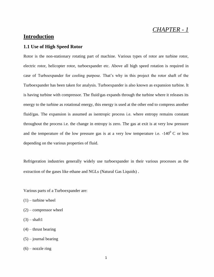
Rotor is the non-stationary rotating part of machine. Various types of rotor are turbine rotor,
electric rotor, helicopter rotor, turboexpander etc. Above all high speed rotation is required in
case of Turboexpander for cooling purpose. That’s why in this project the rotor shaft of the
Turboexpander has been taken for analysis. Turboexpander is also known as expansion turbine. It
is having turbine with compressor. The fluid/gas expands through the turbine where it releases its
energy to the turbine as rotational energy, this energy is used at the other end to compress another
fluid/gas. The expansion is assumed as isentropic process i.e. where entropy remains constant
throughout the process i.e. the change in entropy is zero. The gas at exit is at very low pressure
and the temperature of the low pressure gas is at a very low temperature i.e. -1400
C or less
depending on the various properties of fluid.
Refrigeration industries generally widely use turboexpander in their various processes as the
extraction of the gases like ethane and NGLs (Natural Gas Liquids) .
Various parts of a Turboexpander are:
(1) – turbine wheel
(2) – compressor wheel
(3) – shaft1
(4) – thrust bearing
(5) – journal bearing
(6) – nozzle ring

2
Figure 1.1 - Layout of a Turboexpander (Source- Ghosh P, (2002) [1])
1.2 Working Principle
Figure 1.2 – Schematic of Turboexpander. (Source- Ghosh P, (2002) [1])

3
The gas at very high pressure enters into the turbine through various piping, into the plenum of
the housing and from there into the nozzle. The gas exit from nozzle at very high speed and
strikes the impeller radially. This high speed gas imparts torque to the rotor. Generally
converging-diverging nozzle is used where the pressure of the gas decreases and velocity of the
gas increases at the exit. The pressure energy is transformed into the kinetic energy. From the first
law of thermodynamics it is known that energy always remain conserved. As pressure energy
converts into the kinetic energy the temperature of the gas decreases. These high speed streams
strike against the blade and transmit the forces to the blade and generate torque. The alignment
between the nozzle and the blades are made in such a way that the effect due to sudden changes in
flow direction and loss of energy can be avoided.
The turbine wheel that is used in Turboexpander is of radial or mixed flow type. The radial or
mixed flow turbines are those where the flow enters the wheel radially and exists axially. While
larger units are generally shrouded, smaller wheels are open, the turbine housing acting as the
shroud. When the high speed flow of gas strikes the blade of the turbine, it loses its velocity. That
means the energy of the fluid decreases after the strike. But that energy is being transmitted to the
turbine wheel i.e. work is extracted as the gas expands in turbine. This work extracted can be used
to compress some other gas at another end, generate electricity etc. Due to the loss of energy the
gas at exit is having very low temperature below -1400C or less. These gases can be used in
cryogenic applications like liquefaction of gases. That’s why cryogenic industries use high speed
turboexpander for their applications.

4
Figure 1.3 – cross section view of turboexpander. (Source - Turboexpander-compressor
Technology For Ethylene Plant. General Electric)
1.3 Application
Although turboexpanders are very commonly used in low-temperature processes, they are used in
many other applications as well. This section discusses one of the low temperature processes as
well as some of the other applications.
(1) – power generation
(2) -- Extracting hydrocarbon liquids from natural gas
(3) – Refrigeration system
(4) – power recovery in fluid catalytic cracker
1.4 Present Aim of Work
Due to high rotational speed materials develops stresses and deformation at various locations and
vibrates heavily. Main motive of the thesis is to find critical areas of deformation and stress
concentration in high speed rotor, compressor and expansion turbine wheel used in
turboexpander. After finding those critical areas of stress concentration from analysis of stress
and deformation various modifications in the design has been done. The model, which gives
5
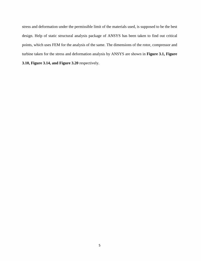
stress and deformation under the permissible limit of the materials used, is supposed to be the best
design. Help of static structural analysis package of ANSYS has been taken to find out critical
points, which uses FEM for the analysis of the same. The dimensions of the rotor, compressor and
turbine taken for the stress and deformation analysis by ANSYS are shown in Figure 3.1, Figure
3.10, Figure 3.14, and Figure 3.20 respectively.
6
CHAPTER - 2
Literature Review
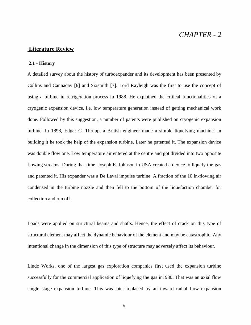
2.1 - History
A detailed survey about the history of turboexpander and its development has been presented by
Collins and Cannaday [6] and Sixsmith [7]. Lord Rayleigh was the first to use the concept of
using a turbine in refrigeration process in 1988. He explained the critical functionalities of a
cryogenic expansion device, i.e. low temperature generation instead of getting mechanical work
done. Followed by this suggestion, a number of patents were published on cryogenic expansion
turbine. In 1898, Edgar C. Thrupp, a British engineer made a simple liquefying machine. In
building it he took the help of the expansion turbine. Later he patented it. The expansion device
was double flow one. Low temperature air entered at the centre and got divided into two opposite
flowing streams. During that time, Joseph E. Johnson in USA created a device to liquefy the gas
and patented it. His expander was a De Laval impulse turbine. A fraction of the 10 in-flowing air
condensed in the turbine nozzle and then fell to the bottom of the liquefaction chamber for
collection and run off.
Loads were applied on structural beams and shafts. Hence, the effect of crack on this type of
structural element may affect the dynamic behaviour of the element and may be catastrophic. Any
intentional change in the dimension of this type of structure may adversely affect its behaviour.
Linde Works, one of the largest gas exploration companies first used the expansion turbine
successfully for the commercial application of liquefying the gas in1930. That was an axial flow
single stage expansion turbine. This was later replaced by an inward radial flow expansion
7
turbine. The new machine was invented by Guido Zerkowitz, an Italian engineer. In this new
design, there was a reversing chamber fitted inside the turbine wheel. In this way by reducing the
wheel speed, the velocity compounding could be achieved. Zerkowitz’s patent gave many details
of turbine construction to reduce refrigerative and piping losses. For instance, the shaft bearings
were to be entirely outside the turbine housing, well removed from the cold zone.
In the year 1939, a Russian scientist Peter Kapitza[11], came up with two revolutionary
conclusion in his paper. These two revolutionary conclusions are:
1. Basing his explanations on thermodynamic principles, he demonstrated that a low
pressure (4-5 bar) liquefier using an expansion turbine would outperform a high pressure
liquefier using a reciprocating expander. Besides having thermodynamic superiority, the
low-pressure plant would be less expensive.
2. By both analytical and experimental studies, he demonstrated that an inward radial flow
turbine would be preferable to an axial impulse type machine. His principal argument
was that in an axial flow machine, the disruption of the regular flow by expansive air
from the rotor would make it difficult to maintain radial equilibrium. The ejection was
ascribed to radial pressure gradient generated by centrifugal forces in the rather dense
working fluid. He advised that cryogenic turbines could follow the general design
principles of radial inflow hydraulic machines, because both dealt with heavy fluids
moving at comparatively low speeds.
During the World War II, standardized turbines were needed. Hydraulic machine concept was
applied. Impeller parameters like specific speed (ns) and flow coefficient (φ) etc. became the
8
criteria for selection of turbines. The centrifugal inflow geometry thus became the usual
configuration for small and medium sized cryogenic turbines [17].
In 1983 a Turboexpander was installed first in natural gas station by San Diego Gas and
Electric. After that, additional installations were made in the mid 1980′s in Memphis, Tennessee,
Stockbridge, Georgia and Hamilton, New Jersey.
Turboexpander with secondary power generation source increase both overall output and
efficiency.
In October of 2008, Enbridge opened a combination turbo expander and fuel cell facility in
Toronto, Canada. The facility produces 2.2 megawatts.
2.2 - Recent Developments
During the period of 1960s and 70s, demand of helium increased. Hence, the demand for energy
efficient liquefiers and refrigerators based on turbines increased. The volumetric flow rate in case
of helium turbines are low due to low fluid temperature and large pressure ratio. Because of that
the operating speed of those turbines is very high, in the order of million revolutions per minute.
At such high speed gas and magnetic bearings are the only alternatives.
Sixsmith first initiated research on small turbo-expanders in the period of 1905s at the University
of Reading. The repercussion of the research came as: A prototype was successfully employed in
a small laboratory sized air liquefier at the university. That brought a remarkable change. Later
getting the idea of this small size turbo-expander, British Oxygen Company (BOC) manufactured
expansion turbines for application in various air separation units. World’s first viable turbine-
based helium liquefier was built by BOC for the Rutherford Laboratory in Oxford. By the end
1950s, England based company “Lucas company” had developed a large number of gas
lubricated inward flow turbines for PDC (Petrocarbon Development Corporation) [18].
9
Later many industries involved in the development process of the turbo-expander. Sulzer Bros.,
Switzerland, La Fleur Corporation, Lucas Corporation and Linde, Germany started constructing
small turbines with gas as the lubrication medium for bearings.
By the 1980s, the design of turboexpanders with gas bearings as its support became almost
popular in Europe and USA. They built two models of small turbines, one for helium liquefiers
and another for small air separation units. Naka Fusion Research Centre affiliated to the Japan
Atomic Energy Institute [13] modelled a very large size He turbo-expander. Ino et al. [14]
developed a He turbo-expander for a 70 MW superconducting generator. The work of Kapitza,
paved the way for the Russian Turbine industries to use both oil and gas bearings to support
turbo-expander. This has continued through the 90s [10]. Small turboexpanders for
microcryogenic systems have also been developed by the Mikrokryogenmash company in
Russia[15].
Gas bearing technology, was applied to applications in small air separation plants. By considering
stringent safety and reliability conditions, expansion turbine of Lucas was employed in a plant
that was supplying blanket gas to a Uranium Hexafluoride (UF6) process. Later taking gas-
bearing based turbine, scientists duo Sulzer Brothers developed a range of small nitrogen
liquefiers (the LINIT series). Now a Germany company Linde AG, manufactures this capacity
and range of laboratory liquefiers.
The development in the field like the micro turbines and application of bearings of a
turboexpander are among various modern developments. A tiny version of the of the turbine for
cryo-cooler was built by Sixsmith[16] in collaboration with Goddard Space Flight Centre of
NASA. They built the turbine with diameter 1.5 mm and tested it with a speed of around one

10
million revolutions per minute. For cooling purpose like infrared detectors and electronic devices
in space as well as ground, these devices are used. While gas bearings of both the aerostatic or
aerodynamic varieties attained good amount of reliability, they still have process gas
consumption, contact in starts and stops, sensitivity to dirt and shocks, and instabilities.
Alternative bearing geometries were analysed by several authors. Foil bearings have been
successfully used in cryogenic turbines. ACD Inc. in USA has used foil, as well as magnetic,
bearings in their machines. Oil bearings have been replaced by magnetic bearings in many large
scale applications including air separation plants and hydrocarbon industries.
2.3 - Organisations Involved in Turboexpander Activities
Companies such as Air Products and Chemicals Inc., USA, L’Air Liquide of France and Linde
AG of Germany manufacture turboexpanders. Creare Inc. [9], USA and Hitachi, Japan
manufacture small helium turbines for small closed cycle cryorefrigerators based on the reverse
Brayton cycle. Creare Inc. has built a range of highly compact and sophisticated turbines, the
smallest of them having a wheel of only 1.5 mm diameter. Hitachi has produced small helium
turbines for both gas phase and supercritical fluid flow. The Japan Atomic Energy Research
Institute, in collaboration with Kobe Steel, manufactures large helium turbines for nuclear
applications. Galiimash, Helium mash and Mikrokryogenmash are major cryogenic
turboexpander manufacturers in Russia.
In India, after years and years of cryogenic research activity, the development in cryogenic
expansion turbines has not been undertaken seriously. One exception is the work of Jadeja et [19].
al. at the Central Mechanical Engineering Research Institute, Durgapur. He developed a radial
flow turbine with the support of gas bearings.
11
2.4 – Analysis of Turboexpander
Turboexpander consist of following parts
1-shaft
2-bearings
3-thrust collar
4-expansion turbine
5-brake compressor
6-housings etc.
Generally various types of turbo machines are used for various types of application. Depending
on size they can be categorized as small, medium and large turbo machines. Various works has
been done by Linde AG of Germany, Creare Inc. [9] USA. Generally shaft, expansion turbine
and brake compressor are taken for analysis of stress and deformation, as the whole assembly is
kept in housing, there is a probability that due to high speed rotation of the Turboexpander, the
various elements of it may grow radially decreasing the clearance between the housing and turbo
expander. This may cause catastrophic damage to the housing and the turbo expander and also to
the bearings. There are sharp edges present in shaft; brake compressor, turbine wheel, and those
are major areas of stress concentration. As turboexpanders are very delicate and costly, it is
imperative to analyze each and every part carefully before putting it into application.
12
CHAPTER – 3
Analysis of Turbomachine
3.1 - Objectives
The objectives of the analysis are:
1. To find out the stress field in rotating components due to very high rotational speed and to
carry out various modifications in the design to avoid failures of rotor.
2. To obtain the deformation of the various elements of the rotor, caused by the centrifugal force
Centrifugal force caused by the high rotational speed deflects the material radially, decreasing
the clearance between casing and the element. If the clearance decreases, then there is
possibility of material, material contact causing wear and tear. That’s why analysis of the
deformation is inevitable.
3. To analyse the rotor system by varying the geometric feature like fillets, thickness on the shaft
collar, compressor etc.
3.2 - Steps for the Stress and Deflection Analysis
Stress and deflection analysis have been carried out by using ANSYS fem solver.
1. First of all the models i.e the rotor, turbine and the compressor have been formulated by using
parametric solid modelling software. We have used Solidworks 2012 for the modelling. The
model is then saved in *.iges/*.igs format (iges stands for initial graphics exchange
specification, which is a neutral data format file that helps in digital exchange of data among
various CAD software).
2. This model is then imported to the ANSYS.
13
3. Meshing of the solid model is generated by using the meshing function of the ANSYS finite
element solver package. Then various boundary conditions are applied to the model and
solved for stress and deflection.
3.3 - Stress Analysis of Rotor Shaft
Objective
The shaft has been analysed to find out whether the maximum stress generated in rotor system is
under the permissible limit or any modification is required to address the problem. Also the
deformation analysis has been carried out to study the radial growth of the disc and the shaft at
the bearing portion.
Solid Model and Mesh Generation
Processes used are as follows:
1. First a 2D drawing is prepared in the Solidworks 2012 software and as this geometry is
symmetric it is revolved around an axis to create the solid model. This is then saved in *.iges
format.
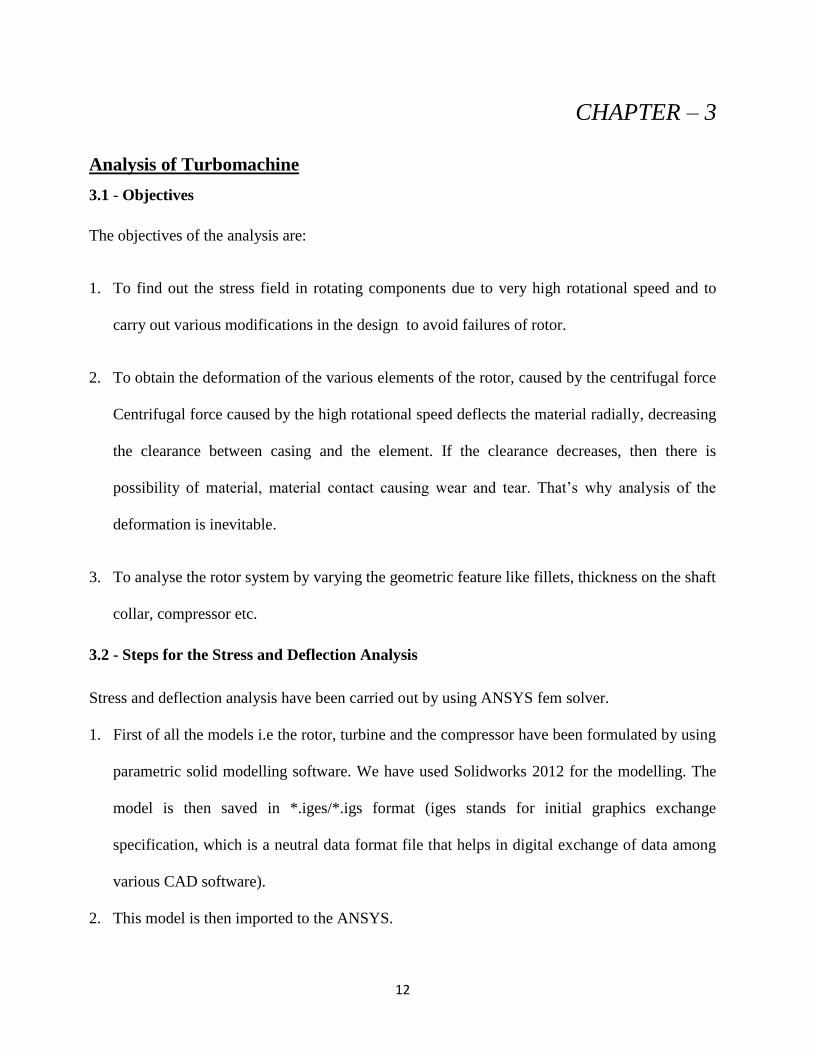
2. The dimension of the shaft is shown in figure 3.1.
Figure 3.1 –Dimension Of Rotor System (source – Ghosh P,(2002)[1]).
14
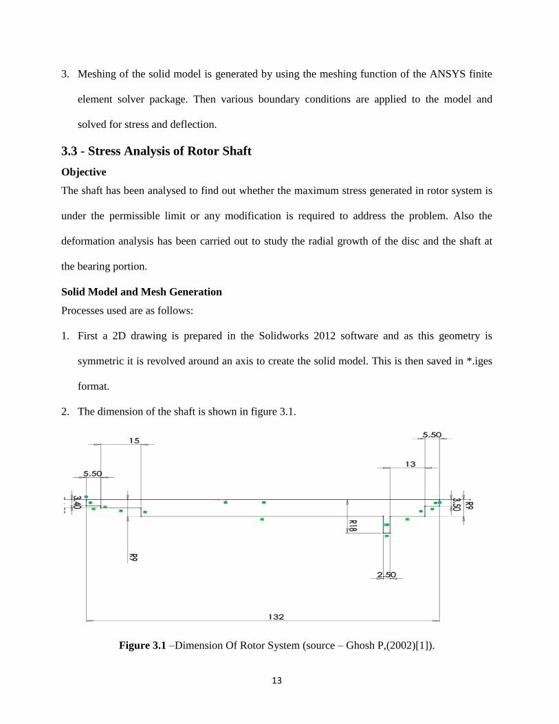
3. The figure 3.2 shows the model generation techniques in Solidworks 2012.The model is saved
in iges format.
Figure 3.2 – Solid Model of Rotor.
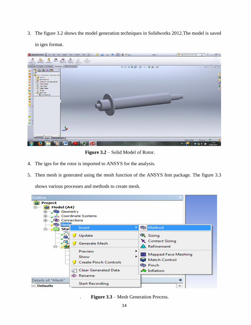
4. The iges for the rotor is imported to ANSYS for the analysis.
5. Then mesh is generated using the mesh function of the ANSYS fem package. The figure 3.3
shows various processes and methods to create mesh.
. Figure 3.3 – Mesh Generation Process.

15
The figure 3.4 shows various methods to create mesh.
Figure 3.4 – Various Methods for Mesh Generation
Tetrahedral mesh generally provides more accurate solution in case of volume meshing than any
other meshing methods that’s why tetrahedron method has been chosen for meshing purpose.
Boundary Conditions
A solid has three translational and three rotational degrees of freedom. To apply various
boundary conditions to the model, some of these have to be constrained. By applying the bearing
at the ends to rotational degrees of freedom is constrained i.e. the rotational motion along X-axis
and Y-axis is zero as shaft axis is along Z direction. Then comes the displacement boundary
condition. As the shaft does not have any lateral displacement, so the translational movement of
the end points of the shaft along the X-axis and Y-axis are set to zero. Then rotational speed is
applied to the shaft along Z-axis.
Application of Load
The shaft is subjected to following loads:
1. Gravitational pull (g) is applied about axis of rotor(-Z Axis),as Rotor is vertically
oriented.

16
2. Centrifugal force (mω2r) in radially outward direction due to rotational speed.
Analysis and Results
1) Mesh method – Tetrahedron; algorithm used – Patch conforming
2) Number of element- 34575
Number of nodes - 20403
3) Material used- structural steel having following properties
A. Density (ρ) – 7850 kg/m3
B. Young’s modulus (E) – 210 GPa
C. Poisson’s ratio (υ)– 0.3
4) Rotational velocity applied is ω = 14660 rad/s.
5) After application of all boundary conditions, the model is solved for the stress and
deformation analysis.
Stress analysis of shaft with Side Collar
In small turbo machines, the position of collar is generally placed on one end of the rotor for
providing space for sensors and instrumentation. The figure 3.5 shows the stress generated at
different points of shaft. It can be seen from the figure that the stress at the root collar is 244MPa,
which is very close to the yielding stress of the material considered in current analysis i.e. 250
MPa. That‘s why some modification in the design or the material is necessary. It is recommended
to use some other high yield stress material other than structural steel. Before changing material
of the shaft we can analysis by modifying the geometry with fillets at the critical areas. So for
current analysis fillets are added to previous geometry at root of the collar with different radius.
17
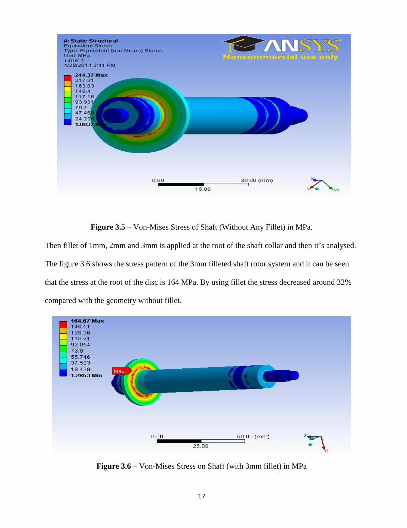
Figure 3.5 – Von-Mises Stress of Shaft (Without Any Fillet) in MPa.
Then fillet of 1mm, 2mm and 3mm is applied at the root of the shaft collar and then it’s analysed.
The figure 3.6 shows the stress pattern of the 3mm filleted shaft rotor system and it can be seen
that the stress at the root of the disc is 164 MPa. By using fillet the stress decreased around 32%
compared with the geometry without fillet.
Figure 3.6 – Von-Mises Stress on Shaft (with 3mm fillet) in MPa
18
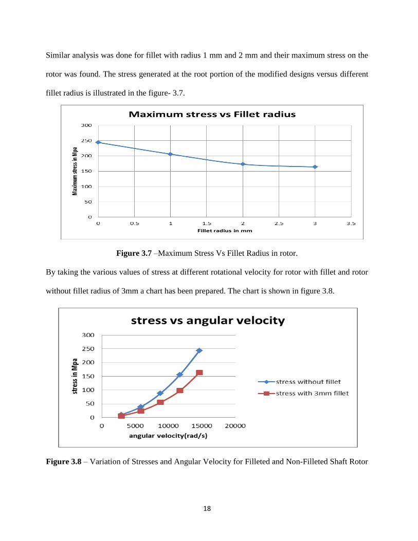
Similar analysis was done for fillet with radius 1 mm and 2 mm and their maximum stress on the
rotor was found. The stress generated at the root portion of the modified designs versus different
fillet radius is illustrated in the figure- 3.7.
Figure 3.7 –Maximum Stress Vs Fillet Radius in rotor.
By taking the various values of stress at different rotational velocity for rotor with fillet and rotor
without fillet radius of 3mm a chart has been prepared. The chart is shown in figure 3.8.
Figure 3.8 – Variation of Stresses and Angular Velocity for Filleted and Non-Filleted Shaft Rotor
19
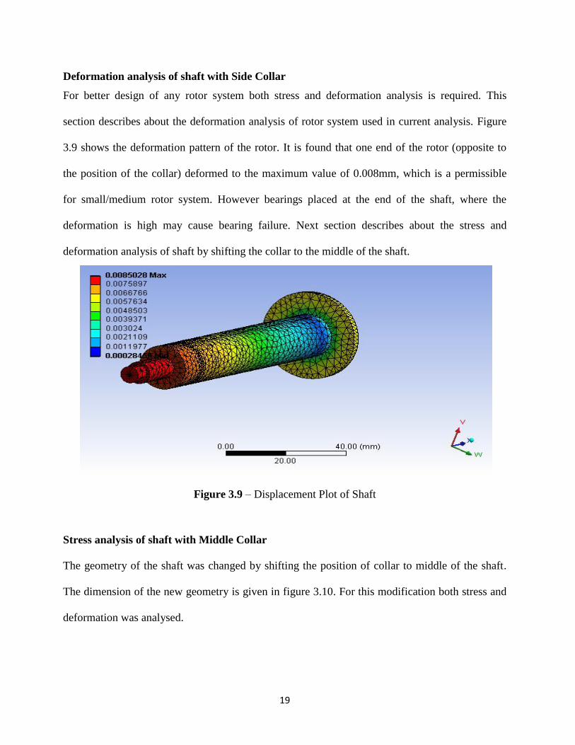
Deformation analysis of shaft with Side Collar
For better design of any rotor system both stress and deformation analysis is required. This
section describes about the deformation analysis of rotor system used in current analysis. Figure
3.9 shows the deformation pattern of the rotor. It is found that one end of the rotor (opposite to
the position of the collar) deformed to the maximum value of 0.008mm, which is a permissible
for small/medium rotor system. However bearings placed at the end of the shaft, where the
deformation is high may cause bearing failure. Next section describes about the stress and
deformation analysis of shaft by shifting the collar to the middle of the shaft.
Figure 3.9 – Displacement Plot of Shaft
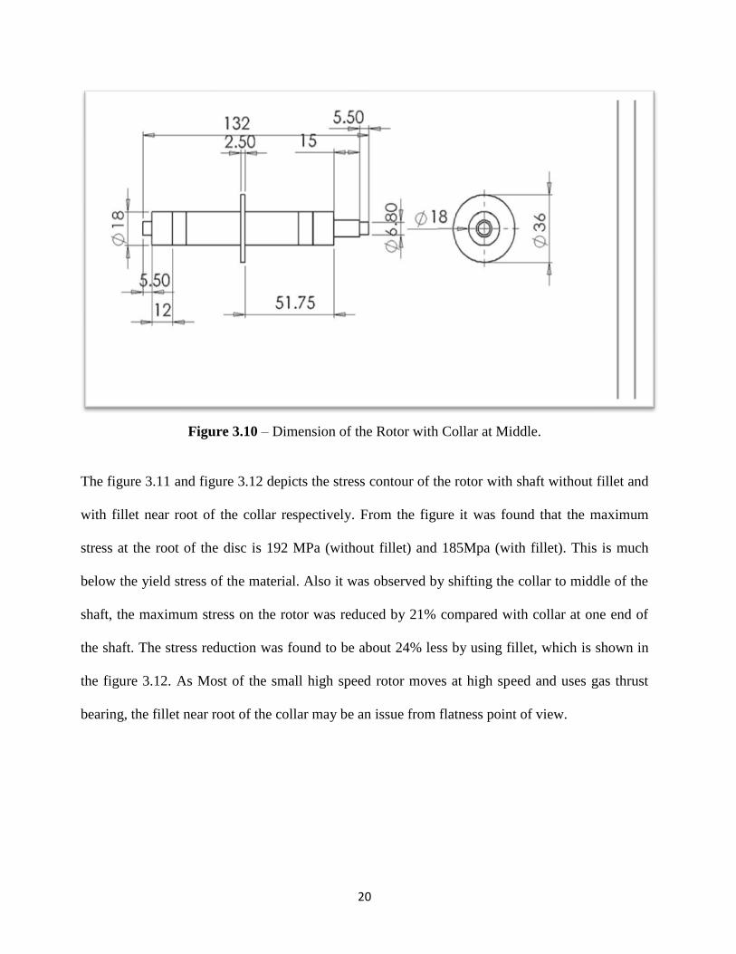
Stress analysis of shaft with Middle Collar
The geometry of the shaft was changed by shifting the position of collar to middle of the shaft.
The dimension of the new geometry is given in figure 3.10. For this modification both stress and
deformation was analysed.
20
Figure 3.10 – Dimension of the Rotor with Collar at Middle.
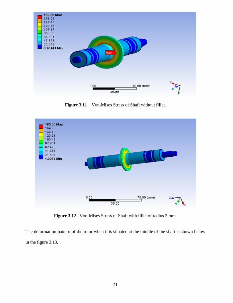
The figure 3.11 and figure 3.12 depicts the stress contour of the rotor with shaft without fillet and
with fillet near root of the collar respectively. From the figure it was found that the maximum
stress at the root of the disc is 192 MPa (without fillet) and 185Mpa (with fillet). This is much
below the yield stress of the material. Also it was observed by shifting the collar to middle of the
shaft, the maximum stress on the rotor was reduced by 21% compared with collar at one end of
the shaft. The stress reduction was found to be about 24% less by using fillet, which is shown in
the figure 3.12. As Most of the small high speed rotor moves at high speed and uses gas thrust
bearing, the fillet near root of the collar may be an issue from flatness point of view.
21
Figure 3.11 – Von-Mises Stress of Shaft without fillet.
Figure 3.12– Von-Mises Stress of Shaft with fillet of radius 3 mm.
The deformation pattern of the rotor when it is situated at the middle of the shaft is shown below
in the figure 3.13.
22
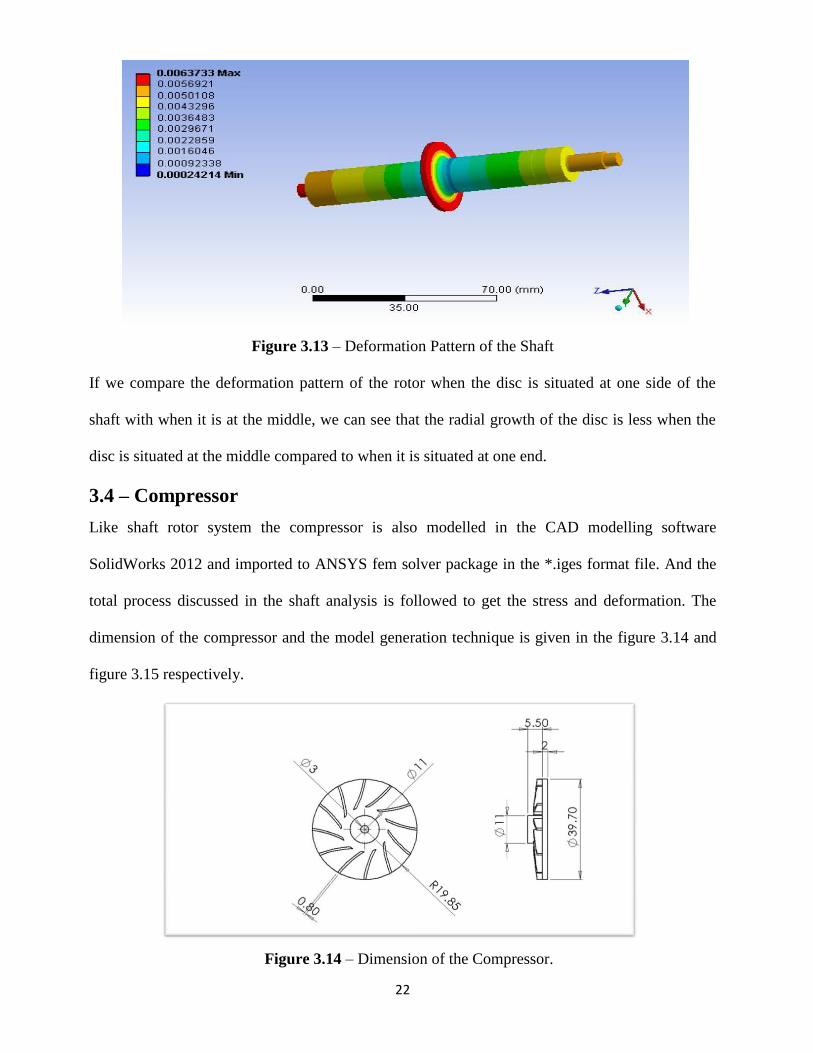
Figure 3.13 – Deformation Pattern of the Shaft
If we compare the deformation pattern of the rotor when the disc is situated at one side of the
shaft with when it is at the middle, we can see that the radial growth of the disc is less when the
disc is situated at the middle compared to when it is situated at one end.
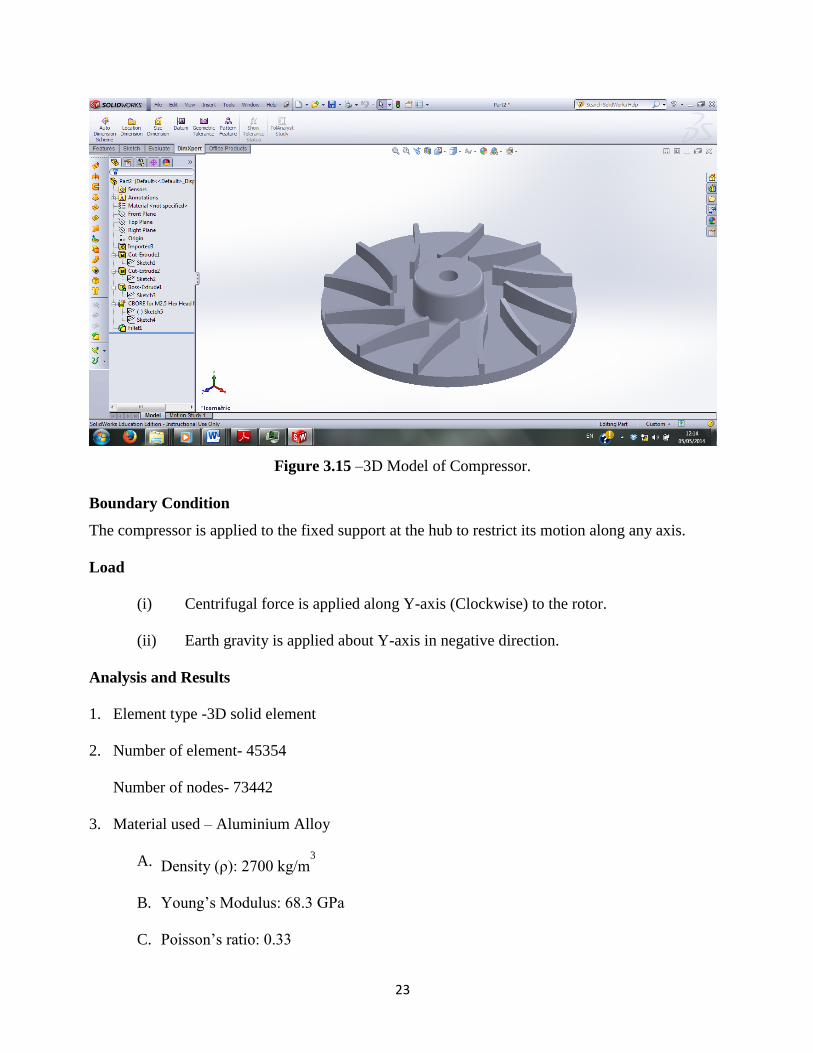
3.4 – Compressor
Like shaft rotor system the compressor is also modelled in the CAD modelling software
SolidWorks 2012 and imported to ANSYS fem solver package in the *.iges format file. And the
total process discussed in the shaft analysis is followed to get the stress and deformation. The
dimension of the compressor and the model generation technique is given in the figure 3.14 and
figure 3.15 respectively.
Figure 3.14 – Dimension of the Compressor.
23
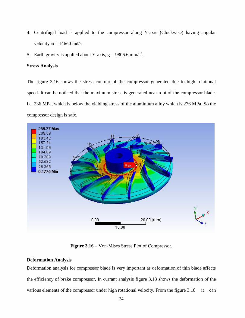
Figure 3.15 –3D Model of Compressor.
Boundary Condition
The compressor is applied to the fixed support at the hub to restrict its motion along any axis.
Load
(i) Centrifugal force is applied along Y-axis (Clockwise) to the rotor.
(ii) Earth gravity is applied about Y-axis in negative direction.
Analysis and Results
1. Element type -3D solid element
2. Number of element- 45354
Number of nodes- 73442
3. Material used – Aluminium Alloy
A. Density (ρ): 2700 kg/m3
B. Young’s Modulus: 68.3 GPa
C. Poisson’s ratio: 0.33
24
4. Centrifugal load is applied to the compressor along Y-axis (Clockwise) having angular
velocity ω = 14660 rad/s.
5. Earth gravity is applied about Y-axis, g= -9806.6 mm/s2.
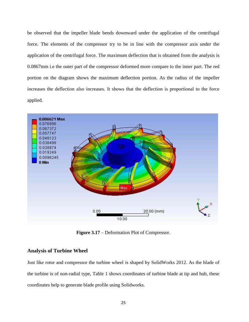
Stress Analysis
The figure 3.16 shows the stress contour of the compressor generated due to high rotational
speed. It can be noticed that the maximum stress is generated near root of the compressor blade.
i.e. 236 MPa, which is below the yielding stress of the aluminium alloy which is 276 MPa. So the
compressor design is safe.
Figure 3.16 – Von-Mises Stress Plot of Compressor.
Deformation Analysis
Deformation analysis for compressor blade is very important as deformation of thin blade affects
the efficiency of brake compressor. In currant analysis figure 3.18 shows the deformation of the
various elements of the compressor under high rotational velocity. From the figure 3.18 it can
25
be observed that the impeller blade bends downward under the application of the centrifugal
force. The elements of the compressor try to be in line with the compressor axis under the
application of the centrifugal force. The maximum deflection that is obtained from the analysis is
0.0867mm i.e the outer part of the compressor deformed more compare to the inner part. The red
portion on the diagram shows the maximum deflection portion. As the radius of the impeller
increases the deflection also increases. It shows that the deflection is proportional to the force
applied.
Figure 3.17 – Deformation Plot of Compressor.
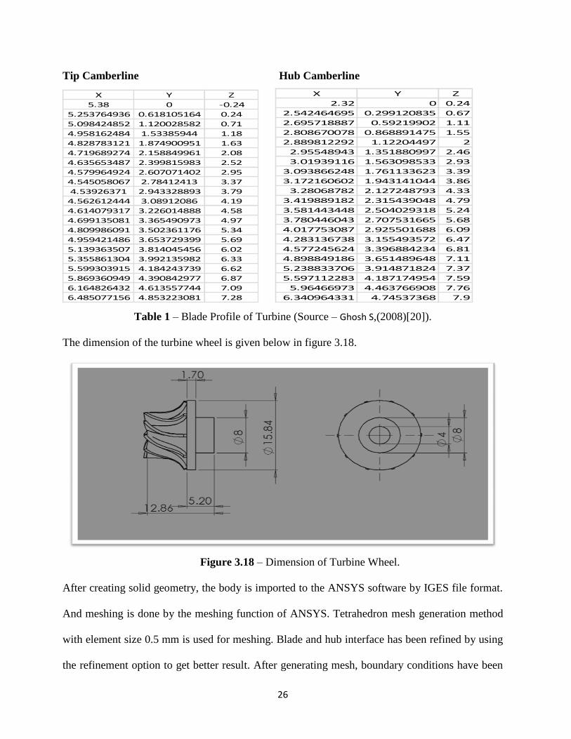
Analysis of Turbine Wheel
Just like rotor and compressor the turbine wheel is shaped by SolidWorks 2012. As the blade of
the turbine is of non-radial type, Table 1 shows coordinates of turbine blade at tip and hub, these
coordinates help to generate blade profile using Solidworks.
26
Tip Camberline Hub Camberline
X Y Z
5.38 0 -0.24
5.253764936 0.618105164 0.24
5.098424852 1.120028582 0.71
4.958162484 1.53385944 1.18
4.828783121 1.874900951 1.63
4.719689274 2.158849961 2.08
4.635653487 2.399815983 2.52
4.579964924 2.607071402 2.95
4.545058067 2.78412413 3.37
4.53926371 2.943328893 3.79
4.562612444 3.08912086 4.19
4.614079317 3.226014888 4.58
4.699135081 3.365490973 4.97
4.809986091 3.502361176 5.34
4.959421486 3.653729399 5.69
5.139363507 3.814045456 6.02
5.355861304 3.992135982 6.33
5.599303915 4.184243739 6.62
5.869360949 4.390842977 6.87
6.164826432 4.613557744 7.09
6.485077156 4.853223081 7.28
X Y Z
2.32 0 0.24
2.542464695 0.299120835 0.67
2.695718887 0.59219902 1.11
2.808670078 0.868891475 1.55
2.889812292 1.12204497 2
2.95548943 1.351880997 2.46
3.01939116 1.563098533 2.93
3.093866248 1.761133623 3.39
3.172160602 1.943141044 3.86
3.28068782 2.127248793 4.33
3.419889182 2.315439048 4.79
3.581443448 2.504029318 5.24
3.780446043 2.707531665 5.68
4.017753087 2.925501688 6.09
4.283136738 3.155493572 6.47
4.577245624 3.396884234 6.81
4.898849186 3.651489648 7.11
5.238833706 3.914871824 7.37
5.597112283 4.187174954 7.59
5.96466973 4.463766908 7.76
6.340964331 4.74537368 7.9
Table 1 – Blade Profile of Turbine (Source – Ghosh S,(2008)[20]).
The dimension of the turbine wheel is given below in figure 3.18.
Figure 3.18 – Dimension of Turbine Wheel.
After creating solid geometry, the body is imported to the ANSYS software by IGES file format.
And meshing is done by the meshing function of ANSYS. Tetrahedron mesh generation method
with element size 0.5 mm is used for meshing. Blade and hub interface has been refined by using
the refinement option to get better result. After generating mesh, boundary conditions have been
27
applied to the geometry for analysis. Fixed support is applied to the hub and rotational speed of
14660 rad/s is given to the turbine around its axis.
Analysis and Result
1. Material chosen- Aluminium Alloy
a. Density (ρ): 2700 kg/m3
b. Young’s Modulus: 68.3 GPa
c. Poisson’s ratio: 0.33
2. Number of element – 19591
Number of nodes - 5856
3. Load – centrifugal load with angular velocity 14660 rad/s along its axis.
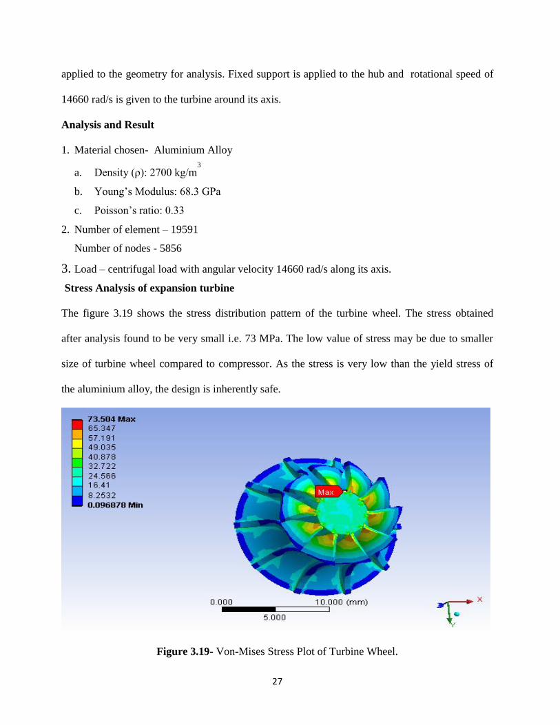
Stress Analysis of expansion turbine
The figure 3.19 shows the stress distribution pattern of the turbine wheel. The stress obtained
after analysis found to be very small i.e. 73 MPa. The low value of stress may be due to smaller
size of turbine wheel compared to compressor. As the stress is very low than the yield stress of
the aluminium alloy, the design is inherently safe.
Figure 3.19- Von-Mises Stress Plot of Turbine Wheel.
28
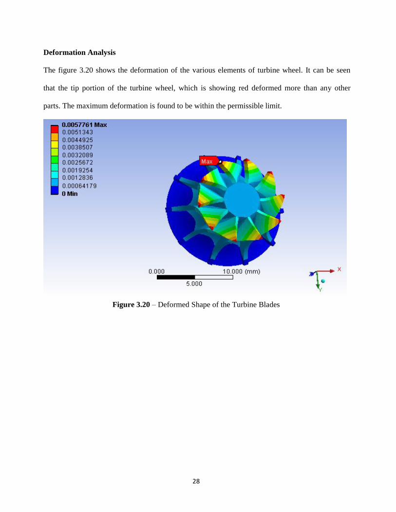
Deformation Analysis
The figure 3.20 shows the deformation of the various elements of turbine wheel. It can be seen
that the tip portion of the turbine wheel, which is showing red deformed more than any other
parts. The maximum deformation is found to be within the permissible limit.
Figure 3.20 – Deformed Shape of the Turbine Blades

29
CHAPTER - 4
Result and Discussion
In the current investigation stress and deformation for different parts of turboexpander is done.
Below are the lists of observation from current analysis.
1. Stress are found to be maximum in the root of the collar which are close to the yield stress
of the material, so to avoid failure of rotor at high speed an attempt is made to redesign the rotor
with different geometry by providing fillet of 3 mm at the root of the collar. By increasing the
fillet size the stress can be further reduced but it may cause improper behavior of gas thrust
bearing.
2. Further an attempt was made to reposition the location of shaft collar from compressor
side end to the middle of the rotor. The analysis of such modification shows there is 21%
reduction in maximum stress at the root of the collar. So current investigation suggest the position
of the collar should be in the middle of the rotor.
3. The radial growth of the disc is more compared to any other part of the shaft. So the size
of collar can be redesigned to reduce based on the load carrying capacity of thrust bearing.
4. The maximum stress distribution in the compressor was found to be near root of the
blades. This can be further reduced by providing fillets at the root of the compressor blade.
Similarly the deformation analysis shows to be high at the outer portion of compressor. To reduce
the stress distribution and the deformation, author suggests changing the material of the
compressor or redesigning the compressor blades.
5. The design of the turbine is most important in turboexpander, the current investigation
found that the stress distribution of turbine wheel with radial entry and axial discharge designed
based on Hasselgruber’s technique is much below the yield stress of the material. Similarly the
maximum deformation and deformation over the blades are found to be under permissible limit.
30
CHAPTER - 5
Conclusion and Future Scope
Current project can be very helpful to the design engineer of turboexpander, which is used mostly
for cryogenic application. The analysis will be very helpful to the engineering society of world to
analyze, design and fabricate small turbomachinery using ANSYS.
Below is the list of future scopes for the project:
1. All components of turboexpander namely rotor, compressor and expansion turbine can be
combined together and a detail analysis can be done to study the critical areas using ANSYS.
2. An analytical analysis of high speed rotor, compressor and expansion turbine using Finite
Element Method can be done and compared with the result obtained from the ANSYS software.
3. Bearings for such high speed turbo machines are critical parts, so analysis of bearings are
needed to complete design of turbo machines.

31
REFERENCES
[1] Ghosh P., Analytical and Experimental Studies on Cryogenic Turboexpander, Ph. D.
dissertation, IIT Kharagpur (2002).
[2] Goel S.K, Theoretical and Experimental Investigation of a Shaft Disc System with a
Crack, B.Tech. dissertation, NIT Rourkela(2008).
[3] Y. D. Kim And C. W. Lee, Journal Of Sound And Vibration. Finite Element
Analysis Of Rotor Bearing Systems Using A Modal Transformation Matrix (1986).
[4] D Martande, S. G. Kolgiri, Nitin S Motgi, IJAIEM (Volume 2, Issue 7, July 2013)Stress
Analysis for Rotor Shaft of Electric Motor.
[5] T. R. Chandrupatla, A.D Belegundu, Finite Elements in Engineering, New Delhi, PHI
private Limited, (2008)
[6] Collins, S.C. and Cannaday, R.L. Expansion Machines for Low Temperature
Processes Oxford University Press (1958)
[7] Sixsmith, H. Miniature cryogenic expansion turbines - a review Adv Cryo Eng (1984) 29
511-523
[8] Reuter K. and Keenan B. A. Cryogenic turboexpanders with magnetic bearings
AICHESymposium Series, Cryogenic Processes and Machinery.
[9] Creare Inc, USA www.creare.com
[10] Kun, L .C. and Sentz, R. N. High efficiency expansion turbines in air separation and
liquefaction plants International Conference on Production and Purification of Coal Gas
& Separation of Air, Beijing, China (1985) 1 – 21
[11] Kapitza, P. J. Phys. Ac. Sci. USSR.1, No.7, p29 (1939)
[12] Dixon, S. L. Fluid Mechanics and Thermodynamics of Turbomachinery (3rd
ed) Pergamon
Press (1978)
[13] Kato T, Miyake, A. Kawno, K. Hamada,K., Hiyama, T., Iwamoto, S., Ebisu, H.,
Tsuli, H.,Saji, N., Kaneko, Y., Asakura, H., Kuboto, M., Nagai, S. Design and test of
wet type Turboexpander with an alternator as Adv Cryo engg (1994)
[14] Ino, N., Machida, A., and Ttsugawa, K., Development of high expansion ratio He
turboexpander Adv Cryo Eng (1992) 37B 835-844
[15] Polishchuk, E. L., Shanklankin V. I. and Lyapin V. I. Self-contained microcryogenic
system with a turboexpander Khimicheskoe I Neftyanoe Mashinostroenie (Trans:
Chemical & Petroleum Engg) (1991) V 27 (3/4) P217
32
[16] Sixsmith, H., Valenjuela, J. and Swift, W. L. Small Brayton cryocoolers Adv Cryo Eng
(1988)
[17] Land, M. L. Expansion turbines and engines for low temperature processes Adv
CryoEng (1957)
[18] Beasley, S. A. and Halford, P. Development of a High Purity Nitrogen Plant using
Expansion Turbine with Gas Bearing Adv Cryo Eng (1965).
[19] Jadeja, H. T., Mitter, A. and Chakrabarty, H. D. Turboexpander application for
cryoprocessing of nitrogen and related gases Proceedings of INCONCRYO85 Indian
Cryogenic Council Tata McGraw(1985)
[20] Ghosh S., Experimental and computational studies on cryogenic Turboexpander Ph.D.
dissertation, NIT Rourkela (2008).