Embed Size (px)
Citation preview

Stress analysis of V-notches with and without cracks,with application to foreign object damage
D Nowell*, D Dini and P DuoÂ
Department of Engineering Science, University of Oxford, UK
Abstract: Gas turbine engines can be subject to ingestion of small hard particles, leading to foreignobject damage. This can take the form of sharp V-notches in the leading edge of blades and there is aneed to predict the initiation and propagation behaviour of fatigue cracks growing from the base ofthe notch. The notch geometry is quite extreme and is not normally covered in standard references fornotch stress concentration factors. Similarly, stress intensity factor solutions for this geometry are notwidely available. This paper uses the dislocation density approach to solve the two-dimensional elasticproblem of a V-notch with a radiused root. Stress concentration factors are found for the notch itself,and stress intensity factors are determined for cracks growing away from the notch for cases ofapplied and residual stress distributions. Comparisons are made with existing notch solutions fromthe literature.
Keywords: notches, cracks, stress concentration factors, stress intensity factors, foreign objectdamage, residual stress
NOTATION
a crack lengthb notch depthbx, by Burgers vector componentsBx, By Burgers vector densitiesG kernel functionKI stress intensity factorKt stress concentration factorN number of points in the discretizationr ordinate along cracks distance from the surface to the root along
the notch boundaryt ordinate along the notch boundaryu normalized ordinate along the notch
boundaryui integration pointvk collocation pointw weight functionx, y Cartesian coordinatesxd, yd dislocation position
e small distancey semi-angle of the notchk Kolosov’s constant
m shear modulusn Poisson’s ratior notch root radiuss0 stress remote from the notchsd stress due to dislocationssNN, sNT tractions on the crack or notch boundaryf rotation angle in stress transformationF bounded part of the dislocation density
distribution
1 INTRODUCTION
Gas turbine engines are used to power many civil andmilitary aircraft. The high air¯ow required results in apowerful suction effect, which can cause the engine toingest solid objects that may cause damage to theengine. These objects generally fall into two categories:
(a) soft objects such as birds or ice and(b) small hard objects such as stones and rivets.
Ingestion of objects in the second category is normallytermed `foreign object damage’ (FOD). Such objectstypically cause damage to the leading edge of the fan orcompressor blades [1]. The damage is often quite small,taking the form of a `nick’ in the leading edge, so that itcan be dif®cult to pick up during a simple visualinspection of the engine prior to ¯ight. The presence ofthe FOD will reduce the fatigue strength of the blade
The MS was received on 29 January 2003 and was accepted afterrevision for publication on 12 June 2003.* Corresponding author: Department of Engineering Science, Universityof Oxford, Parks Road, Oxford OX1 3PJ, UK.
429
S01103 # IMechE 2003 J. Strain Analysis Vol. 38 No. 5

and can lead to failure under normal levels of bladevibration. In recent years there has been increasinginterest in predicting the effect of FOD on blade fatiguestrength [2]. The objectives of this work are to providetools which will enable the assessment of damagedblades in service and the development of FOD-resistantdesigns of blade. FOD observed in service can varyconsiderably in size and geometry, due to the range ofobjects ingested and the widely varying impact speeds,location and orientation [1]. Experimental work toreproduce this type of damage in the laboratory hasbeen undertaken by a number of workers (see, forexample, references [3] and [4]). A range of projectileshas been used, but there is widespread agreement thatthe largest reduction in fatigue strength is found fromsharp V-notches in the leading edge. Figure 1 showstypical damage created by a laboratory gas gun usinghardened steel cubes [3].
Alongside the experimental work in this area,attempts have been made to predict the loss of fatiguestrength caused by FOD [3, 5]. In order to carry out afatigue assessment it is necessary to know the stresses inthe neighbourhood of an FOD notch and, if a fracturemechanics approach is to be used, stress intensity factorsfor cracks emanating from the notch. The required toolsare, however, not readily available in the literature.Sharp FOD notches have higher stress concentration…Kt† values than most features that would be designedinto a component and appropriate Kt solutions do notappear in standard reference works [6]. Similar remarksapply to the case where a crack is present. Againstandard reference works [7] give very few solutionswhich apply to sharp V-notches. Clearly it would bepossible to pursue a solution based on ®nite elementprocedures, but the overall requirement suggests that arange of geometries and crack lengths will need to beinvestigated. It may also be necessary to include theeffects of residual stress, either from pre-existing surface
treatment or arising from the impact itself. It isappropriate, therefore, to pursue a more specializedapproach that will be capable of investigating a range ofgeometries, parametrically described. The techniquechosen here is based on the dislocation density method[8, 9] which has been found to be effective for two-dimensional cracks and slots. In effect the method maybe considered as a displacement discontinuity boundaryelement method, employing a small number of high-order elements.
2 NOTCHES WITHOUT CRACKS
2.1 Formulation
The general geometry of the notch that is to be analysedis shown in Fig. 2a. The notch depth is b, and the notchangle is 2y. The root of the notch has a radius of r. Inthe case of a real FOD notch, the boundaries of theblade (other than the leading edge itself) will be remotefrom the notch. Therefore a notch in a half-plane (i.e.with a single free boundary) was chosen for considera-tion. In this case, the notch can be uniquely described byy and r=b. As stated above, the analysis employed willbe two dimensional and also elastic material behaviourwill be assumed. It is recognized that there may be somemacroscopic cyclic plasticity during fatigue loading of adamaged component, but an elastic analysis would stillappear to be an appropriate place to start. If the notch isloaded by a stress in the y direction, symmetry will applyand the problem can be simpli®ed by considering onlyhalf of the notch (Fig. 2b). Simple geometry shows thatthe half-length of the free boundary of the notch, s, isgiven by
s
bˆ 1
cos y‡ r
btan y ‡ p
2¡ y ¡ 1
cos y
³ ´…1†
The case where a uniform far-®eld stress s0 is appliedparallel to the free surface (i.e. in the y direction) isconsidered. A point on the boundary of the notch willexperience an unsatis®ed normal traction sNN and anunsatis®ed shear traction sNT given by the two-dimen-sional stress transformation equations as
sNN ˆ s0
2‰1 ‡ cos…2f†Š …2†
sNT ˆ s0
2sin…2f† …3†
where f is the angle between the local boundary of thenotch and the y axis. It is noted that f ˆ ¡ y on thestraight part of the notch boundary and varies from ¡ yto ¡ p=2 over the curved portion at the root. Theseunsatis®ed tractions are to be met by installing arrays ofdisplacement discontinuities (or dislocations) along theboundary of the notch. The stress ®eld due to a
Fig. 1 Typical FOD notch on the leading edge of acompressor blade
D NOWELL, D DINI AND P DUOÂ430
J. Strain Analysis Vol. 38 No. 5 S01103 # IMechE 2003

dislocation positioned at …xd, yd† with Burgers vectorcomponents bx in the x direction and by in the ydirection (Fig. 3) is ®rst described. The stress com-ponents at a remote point …x, y† due to the Burgersvector component bk are given by
sdijk ˆ m
p…k ‡ 1†bkGkij…x, xd, y ¡ yd† …4†
where m is the shear modulus and k is Kolosov’sconstant [equal to …3 ¡ 4n† in plane strain and…3 ¡ n†=…1 ‡ n† in plane stress, where n is Poisson’sratio]. The functions Gkij are simple algebraic functions,given in reference [9].
Rather than installing discrete dislocations it isarranged to install continuous distributions of Burgersvector densities Bx and By along the boundary of thenotch …0 < t < s† (Fig. 2b). The total stress at a point
…x, y† due to these distributions will therefore be
sdij ˆ m
p…k ‡ 1†
…s
0
BxGxij…x, xd, y ¡ yd† dt
‡ mp…k ‡ 1†
… s
0
ByGyij…x, xd, y ¡ yd† dt …5†
In order to take account of symmetry it is recognizedthat there will also need to be distributions on the left-hand side of the notch, with densities given by
Bx…xd, ¡ yd† ˆ ¡ Bx…xd, yd† …6†
and
By…xd, ¡ yd† ˆ By…xd, yd† …7†
so that the total stress due to distributions on both sides
Fig. 2 (a) Geometry of an idealized two-dimensional V-notch; (b) half-problem analysed, taking advantageof symmetry
Fig. 3 A dislocation in a half-plane with Burgers vector strengths bx and by in the x and y directionsrespectively
STRESS ANALYSIS OF V-NOTCHES WITH AND WITHOUT CRACKS 431
S01103 # IMechE 2003 J. Strain Analysis Vol. 38 No. 5

of the notch may now be expressed as
sdij ˆ m
p…k ‡ 1†
…s
0
BxG0xij…x, xd, y ¡ yd† dt
‡m
p…k ‡ 1†
…s
0
ByG0yij…x, xd, y ¡ yd† dt …8†
where
G0xij…x, xd, y ¡ yd† ˆ Gxij…x, xd, y ¡ yd†
¡ Gxij…x, xd, y ‡ yd† …9†
and
G0yij…x, xd, y ¡ yd† ˆ Gyij…x, xd, y ¡ yd†
‡ Gyij…x, xd, y ‡ yd† …10†
It is convenient to express these stresses in compo-nents normal and tangential to the notch surface so that
sdNN ˆ
mp…k ‡ 1†
…s
0
BxG0x NN…x, xd, y, yd, f† dt
‡ mp…k ‡ 1†
…s
0
ByG0y NN…x, xd, y, yd, f† dt …11†
and
sdNT ˆ
mp…k ‡ 1†
…s
0
BxG0x NT…x, xd, y, yd, f† dt
‡ mp…k ‡ 1†
…s
0
ByGy NT…x, xd, y, yd, f† dt …12†
where
Gk NN ˆG0
kxx ‡ G0kyy
2¡
G0kxx ¡ G0
kyy
2cos…2f†
¡ G0kxy sin…2f† …13†
Gk NT ˆG0
kyy ¡ G0kxx
2sin…2f† ‡ G0
kxy cos…2f† …14†
It is now noted that the stresses due to the dislocationdistributions must cancel the original unsatis®ed trac-tions along the surface of the notch so that
sNN ‡ sdNN ˆ 0, 0 < t < s …15†
and
sNT ‡ sdNT ˆ 0, 0 < t < s …16†
Substitution of equations (2) and (11) into equation (15)and of equations (3) and (12) into equation (16) givestwo simultaneous equations in the unknown Burgersvector densities Bx and By. It should be noted that thesedisplay Cauchy singularities because of the nature of thein¯uence functions G. Standard numerical techniquesare available for the solution of this type of problem.Full details have been given in reference [8] or [10], and
only a brief outline will be given here. The steps are asfollows:
1. Normalize the limits of integration to +1 by anappropriate change of variables. In this case u ˆ ¡ 1corresponds to t ˆ 0 and u ˆ 1 corresponds to t ˆ s,so that u ˆ 2t=s ¡ 1.
2. Consider the behaviour of the unknown function atthe ends of the interval. Here we expect bounded andnon-zero behaviour at both ends of the interval t ˆ 0,s, except for Bx at t ˆ s, where the function will bebounded and zero [equation (6)]. Gauss±Jacobi orGauss±Chebyshev quadrature is appropriate forCauchy-singular integral equations and this offersthe option of bounded and zero or r¡0:5 behaviour ateach end point [10]. It has been shown thatincorporation of a stronger singularity than thatpresent is generally satisfactory [11], and here afundamental function giving r¡0:5 behaviour at t ˆ s,with bounded and zero behaviour at t ˆ 0, will bechosen. This choice will also be appropriate later,when a crack is added, emanating from the root ofthe notch. It will also be shown to give acceptablebehaviour for the case without a crack. AccordinglyBk is modelled as the product of a bounded functionFk…t† and a weight function w…t† with
w…t† ˆ����������1 ‡ t
1 ¡ t
r…17†
so that
Bk ˆ Fk…t†����������1 ‡ t
1 ¡ t
r…18†
3. Gauss±Jacobi integration is now applied to reducethe integral equations to a series of 2N simultaneouslinear equations, enforced at N collocation points:
sNN ‡ mp…k ‡ 1†
XN
iˆ1
2p…1 ‡ ui†2N ‡ 1
G0x NN…ui,vk†Fx…ui†
‡ mp…k ‡ 1†
XN
iˆ1
2p…1 ‡ ui†2N ‡ 1
G0y NN…ui,vk†Fy…ui†
ˆ 0 …19†
and
sNT ‡ mp…k ‡ 1†
XN
iˆ1
2p…1 ‡ ui†2N ‡ 1
G0xNT…ui,vk†Fx…ui†
‡ mp…k ‡ 1†
XN
iˆ1
2p…1 ‡ ui†2N ‡ 1
G0y NT…ui,vk†Fy…ui†
ˆ 0 …20†
D NOWELL, D DINI AND P DUOÂ432
J. Strain Analysis Vol. 38 No. 5 S01103 # IMechE 2003

where the integration points ui are given by
ui ˆ cos2i ¡ 1
2N ‡ 1p
³ ´, i ˆ 1, 2, . . . , N …21†
and the collocation points vk by
vk ˆ cos2k
2N ‡ 1p
³ ´, i ˆ 1, 2, . . . , N …22†
For acceptable accuracy, N is usually chosen in therange 50 < N < 100. The simultaneous equationsmay be solved by an appropriate procedure (e.g. LUdecomposition). The results presented in this paperwere obtained with N ˆ 70.
4. Once Fx…ui† and Fy…ui† have been determined, stresscomponents due to the dislocations at a general point…x, y† in the half-plane may be found using similarexpressions to equations (19) and (20), speci®cally
sdij ˆ m
p…k ‡ 1†XN
iˆ1
2p…1 ‡ ui†2N ‡ 1
G0xij…ui, x, y†Fx…ui†
‡m
p…k ‡ 1†XN
iˆ1
2p…1 ‡ ui†2N ‡ 1
G0y NT…ui, x, y†Fy…ui†
…23†
It should be noted that in this case the integrals arenot Cauchy provided that …x, y† does not lie on theboundary of the notch. The validity of the expressionis not, therefore, limited to speci®c collocation points.To evaluate the total stress state it is merely necessary
to add the original stress state in the absence of thenotch, in this case syy ˆ s0.
2.2 Results
It is appropriate to start by examining the validity of theassumptions regarding the end-point behaviour of thedislocation density. Figure 4 shows normalized Bx andBy as functions of position t/s for a number of samplecases. It may be seen that, apart from the ®nalintegration points, a smooth representation of thefunctions is obtained. Thus, it may be concluded thatprecise modelling of end-point behaviour is not neces-sary in this case. It is also noted that increasing the tipradius gives lower density curves in the neighbourhoodof the notch tip. Figure 5 gives the variation in the syy
stress component along y ˆ 0, i.e. the vertical linepassing through the root of the notch for y ˆ 45¯ and anumber of different root radii b=r. It will be noted thatthe stress component is effectively zero for x < b,corresponding to the portion of the half-plane `removed’to create the notch by clearing the boundaries oftractions. For x > b, stresses are close to the far-®eldvalue s0 remote from the notch and increase to a valueequal to Kts0 at the notch root, where Kt is the elasticstress concentration factor for the notch. Some care isnecessary in evaluating Kt; the numerical scheme willresult in a stress ®eld which is continuous, since nodiscrete dislocations are employed. In practice, thereshould be a discontinuity in the syy stress componentbetween 0 at x ˆ b ¡ e and Kts0 at x ˆ b ‡ e, where e is
Fig. 4 Variation in Burgers vector density for a 458 notch with r=b ˆ 0:5
STRESS ANALYSIS OF V-NOTCHES WITH AND WITHOUT CRACKS 433
S01103 # IMechE 2003 J. Strain Analysis Vol. 38 No. 5

a small distance. This discontinuity is not preciselycaptured by the scheme, although Fig. 5 shows that theapproximation is very good. Simply evaluating the stressat x ˆ b will give a value which is between 0 and Kts0. Asatisfactory approach for determining Kt is to use linearextrapolation from two points close to x ˆ b. Valuesof Kt given here were obtained by extrapolation usingx ˆ b ‡ 0:05r and x ˆ b ‡ 0:01r. Figure 5 shows thatthe stresses are strongly dependent on r close to thenotch root but are almost independent of r further
away. This point is emphasized if the stresses are plottedusing a different normalization (Fig. 6). Here syy=Kts0 isplotted against …x ¡ b†=r. It may be seen that theresponse close to the notch may be described by r alone;i.e. the stresses are independent of b, other than throughthe in¯uence of r=b on Kt.
Figure 7 shows the variation in the syy stress alongy ˆ 0 for r=b ˆ 0:2 and several different notch angles y.It will be seen that the in¯uence of notch angle at thisvalue of r=b is very small for y < 45¯. The implication of
Fig. 6 syy stress component plotted normalized with respect to Kt and r to show the dependence on thenotch root radius
Fig. 5 syy stress component along y ˆ 0, y ˆ 45¯ (SCF, stress concentration factor)
D NOWELL, D DINI AND P DUOÂ434
J. Strain Analysis Vol. 38 No. 5 S01103 # IMechE 2003
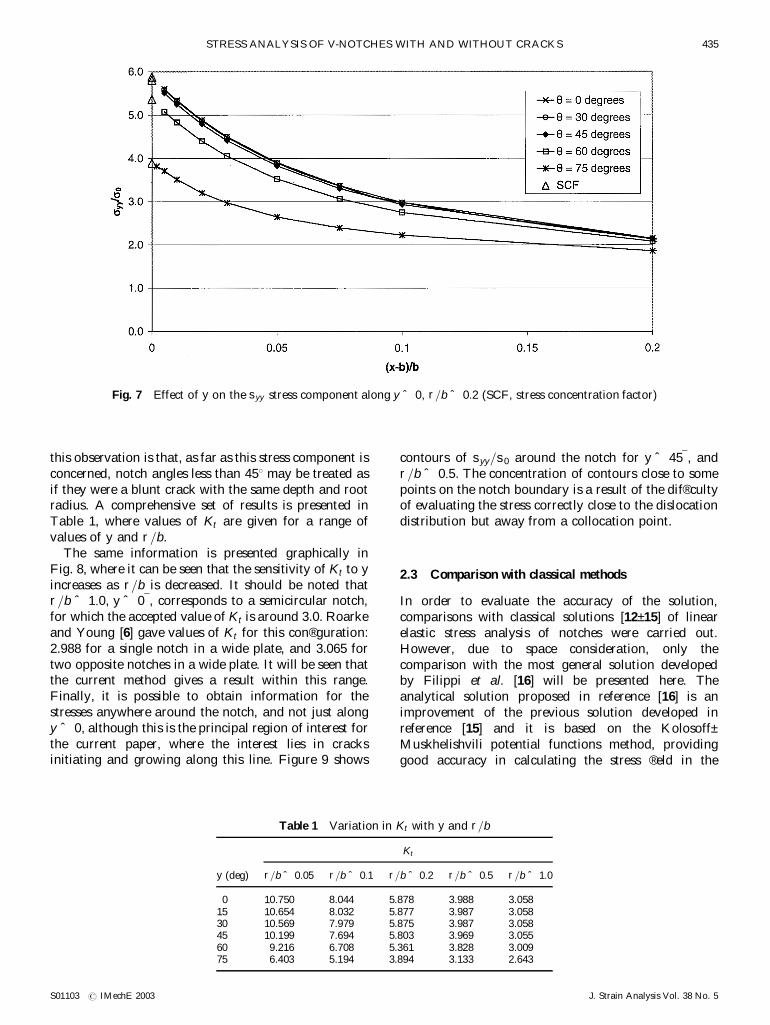
this observation is that, as far as this stress component isconcerned, notch angles less than 458 may be treated asif they were a blunt crack with the same depth and rootradius. A comprehensive set of results is presented inTable 1, where values of Kt are given for a range ofvalues of y and r=b.
The same information is presented graphically inFig. 8, where it can be seen that the sensitivity of Kt to yincreases as r=b is decreased. It should be noted thatr=b ˆ 1:0, y ˆ 0¯, corresponds to a semicircular notch,for which the accepted value of Kt is around 3.0. Roarkeand Young [6] gave values of Kt for this con®guration:2.988 for a single notch in a wide plate, and 3.065 fortwo opposite notches in a wide plate. It will be seen thatthe current method gives a result within this range.Finally, it is possible to obtain information for thestresses anywhere around the notch, and not just alongy ˆ 0, although this is the principal region of interest forthe current paper, where the interest lies in cracksinitiating and growing along this line. Figure 9 shows
contours of syy=s0 around the notch for y ˆ 45¯, andr=b ˆ 0:5. The concentration of contours close to somepoints on the notch boundary is a result of the dif®cultyof evaluating the stress correctly close to the dislocationdistribution but away from a collocation point.
2.3 Comparison with classical methods
In order to evaluate the accuracy of the solution,comparisons with classical solutions [12±15] of linearelastic stress analysis of notches were carried out.However, due to space consideration, only thecomparison with the most general solution developedby Filippi et al. [16] will be presented here. Theanalytical solution proposed in reference [16] is animprovement of the previous solution developed inreference [15] and it is based on the Kolosoff±Muskhelishvili potential functions method, providinggood accuracy in calculating the stress ®eld in the
Fig. 7 Effect of y on the syy stress component along y ˆ 0, r=b ˆ 0:2 (SCF, stress concentration factor)
Table 1 Variation in Kt with y and r=b
Kt
y (deg) r=b ˆ 0:05 r=b ˆ 0:1 r=b ˆ 0:2 r=b ˆ 0:5 r=b ˆ 1:0
0 10.750 8.044 5.878 3.988 3.05815 10.654 8.032 5.877 3.987 3.05830 10.569 7.979 5.875 3.987 3.05845 10.199 7.694 5.803 3.969 3.05560 9.216 6.708 5.361 3.828 3.00975 6.403 5.194 3.894 3.133 2.643
STRESS ANALYSIS OF V-NOTCHES WITH AND WITHOUT CRACKS 435
S01103 # IMechE 2003 J. Strain Analysis Vol. 38 No. 5

neighbourhood of a semi-in®nite V-notch. Figure 10shows a comparison between the results obtained fromthe present numerical method and the theoreticalanalytical solution given in reference [16]. It is clearlyseen that, for values close to the notch tip, thesolutions are almost coincident but they diverge for
large values of …x ¡ b†=r (as shown in Fig. 10). This isclearly due to the semi-in®nite assumption used inreference [16], where b is assumed to be in®nite.Hence, the stresses depend only on …x ¡ b†=r and y.The region of validity of this assumption may befound by reference to Fig. 6. Another obvious
Fig. 9 Contours of syy=s0 around the notch root for y ˆ 45¯ and r=b ˆ 0:5
Fig. 8 Stress concentration factors for the notch, as a function of y and r=b
D NOWELL, D DINI AND P DUOÂ436
J. Strain Analysis Vol. 38 No. 5 S01103 # IMechE 2003
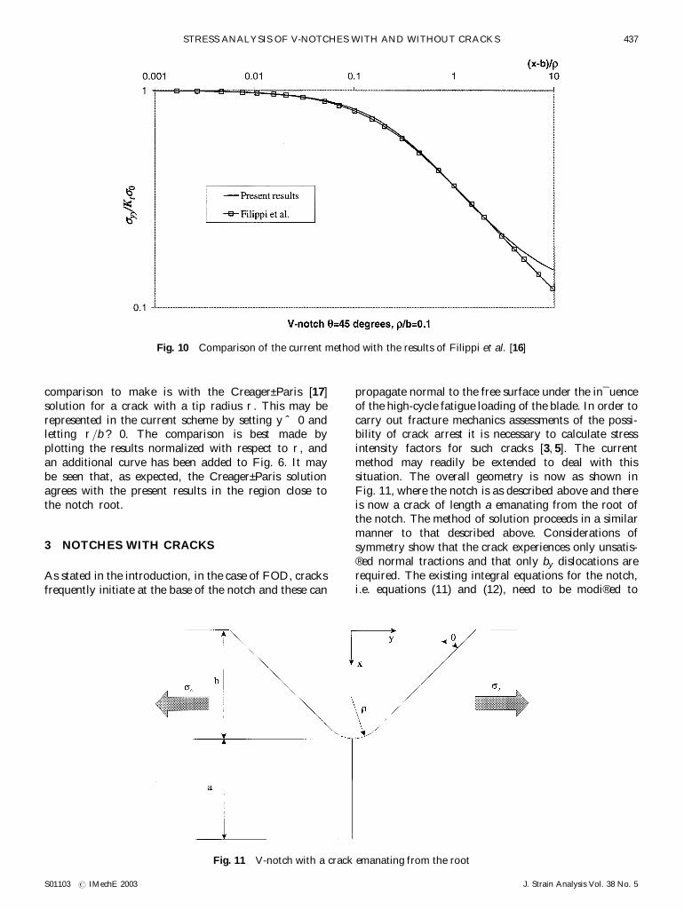
comparison to make is with the Creager±Paris [17]solution for a crack with a tip radius r. This may berepresented in the current scheme by setting y ˆ 0 andletting r=b ? 0. The comparison is best made byplotting the results normalized with respect to r, andan additional curve has been added to Fig. 6. It maybe seen that, as expected, the Creager±Paris solutionagrees with the present results in the region close tothe notch root.
3 NOTCHES WITH CRACKS
As stated in the introduction, in the case of FOD, cracksfrequently initiate at the base of the notch and these can
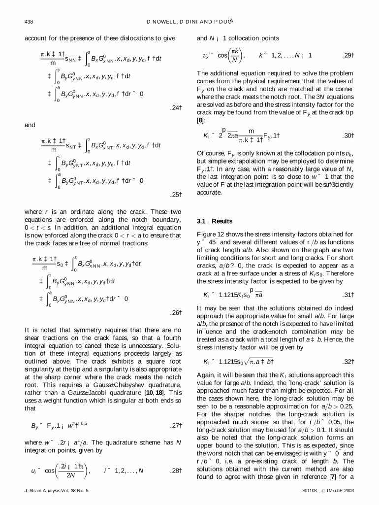
propagate normal to the free surface under the in¯uenceof the high-cycle fatigue loading of the blade. In order tocarry out fracture mechanics assessments of the possi-bility of crack arrest it is necessary to calculate stressintensity factors for such cracks [3, 5]. The currentmethod may readily be extended to deal with thissituation. The overall geometry is now as shown inFig. 11, where the notch is as described above and thereis now a crack of length a emanating from the root ofthe notch. The method of solution proceeds in a similarmanner to that described above. Considerations ofsymmetry show that the crack experiences only unsatis-®ed normal tractions and that only by dislocations arerequired. The existing integral equations for the notch,i.e. equations (11) and (12), need to be modi®ed to
Fig. 10 Comparison of the current method with the results of Filippi et al. [16]
Fig. 11 V-notch with a crack emanating from the root
STRESS ANALYSIS OF V-NOTCHES WITH AND WITHOUT CRACKS 437
S01103 # IMechE 2003 J. Strain Analysis Vol. 38 No. 5
account for the presence of these dislocations to give
p…k ‡ 1†m
sNN ‡…s
0
BxG0x NN…x, xd, y, yd, f† dt
‡…s
0
ByG0y NN…x, xd, y, yd; f† dt
‡…a
0
ByG0y NN…x, xd, y, yd, f† dr ˆ 0
…24†
and
p…k ‡ 1†m
sNT ‡…s
0
BxG0x NT…x, xd, y, yd, f† dt
‡…s
0
ByG0y NT…x, xd, y, yd, f† dt
‡…a
0
ByG0y NT…x, xd, y, yd, f† dr ˆ 0
…25†
where r is an ordinate along the crack. These twoequations are enforced along the notch boundary,0 < t < s. In addition, an additional integral equationis now enforced along the crack 0 < r < a to ensure thatthe crack faces are free of normal tractions:
p…k ‡ 1†m
s0 ‡…s
0
BxG0x NN…x, xd, y, yd† dt
‡…s
0
ByG0y NN…x, xd, y, yd† dt
‡…a
0
ByG0y NN…x, xd, y, yd† dr ˆ 0
…26†
It is noted that symmetry requires that there are noshear tractions on the crack faces, so that a fourthintegral equation to cancel these is unnecessary. Solu-tion of these integral equations proceeds largely asoutlined above. The crack exhibits a square rootsingularity at the tip and a singularity is also appropriateat the sharp corner where the crack meets the notchroot. This requires a Gauss±Chebyshev quadrature,rather than a Gauss±Jacobi quadrature [10, 18]. Thisuses a weight function which is singular at both ends sothat
By ˆ Fy…1 ¡ w2†¡0:5 …27†
where w ˆ …2r ¡ a†=a. The quadrature scheme has Nintegration points, given by
ui ˆ cos…2i ¡ 1†p
2N
³ ´, i ˆ 1, 2, . . . , N …28†
and N ¡ 1 collocation points
vk ˆ cospk
N
³ ´, k ˆ 1, 2, . . . , N ¡ 1 …29†
The additional equation required to solve the problemcomes from the physical requirement that the values ofFy on the crack and notch are matched at the cornerwhere the crack meets the notch root. The 3N equationsare solved as before and the stress intensity factor for thecrack may be found from the value of Fy at the crack tip[8]:
KI ˆ 2��������2pa
p mp…k ‡ 1† Fy…1† …30†
Of course, Fy is only known at the collocation points vk,but simple extrapolation may be employed to determineFy…1†. In any case, with a reasonably large value of N,the last integration point is so close to w ˆ 1 that thevalue of F at the last integration point will be suf®cientlyaccurate.
3.1 Results
Figure 12 shows the stress intensity factors obtained fory ˆ 45¯ and several different values of r=b as functionsof crack length a/b. Also shown on the graph are twolimiting conditions for short and long cracks. For shortcracks, a=b ? 0, the crack is expected to appear as acrack at a free surface under a stress of Kts0. Thereforethe stress intensity factor is expected to be given by
KI ˆ 1:1215Kts0
������pa
p…31†
It may be seen that the solutions obtained do indeedapproach the appropriate value for small a/b. For largea/b, the presence of the notch is expected to have limitedin¯uence and the crack±notch combination may betreated as a crack with a total length of a ‡ b. Hence, thestress intensity factor will be given by
KI ˆ 1:1215s0
�����������������p…a ‡ b†
p…32†
Again, it will be seen that the KI solutions approach thisvalue for large a/b. Indeed, the `long-crack’ solution isapproached much faster than might be expected. For allthe cases shown here, the long-crack solution may beseen to be a reasonable approximation for a=b > 0:25.For the sharper notches, the long-crack solution isapproached much sooner so that, for r=b ˆ 0:05, thelong-crack solution may be used for a=b > 0:1. It shouldalso be noted that the long-crack solution forms anupper bound to the solution. This is as expected, sincethe worst notch that can be envisaged is with y ˆ 0¯ andr=b ˆ 0, i.e. a pre-existing crack of length b. Thesolutions obtained with the current method are alsofound to agree with those given in reference [7] for a
D NOWELL, D DINI AND P DUOÂ438
J. Strain Analysis Vol. 38 No. 5 S01103 # IMechE 2003
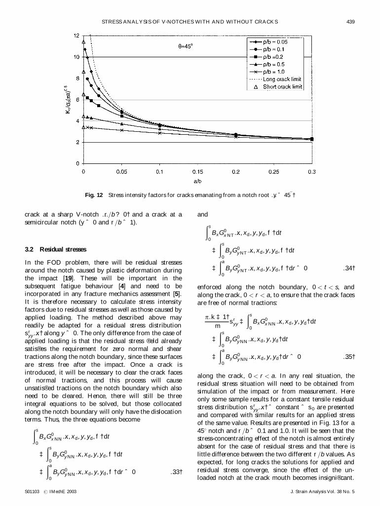
crack at a sharp V-notch …r=b ? 0† and a crack at asemicircular notch (y ˆ 0 and r=b ˆ 1).
3.2 Residual stresses
In the FOD problem, there will be residual stressesaround the notch caused by plastic deformation duringthe impact [19]. These will be important in thesubsequent fatigue behaviour [4] and need to beincorporated in any fracture mechanics assessment [5].It is therefore necessary to calculate stress intensityfactors due to residual stresses as well as those caused byapplied loading. The method described above mayreadily be adapted for a residual stress distributionsr
yy…x† along y ˆ 0. The only difference from the case ofapplied loading is that the residual stress ®eld alreadysatis®es the requirement for zero normal and sheartractions along the notch boundary, since these surfacesare stress free after the impact. Once a crack isintroduced, it will be necessary to clear the crack facesof normal tractions, and this process will causeunsatis®ed tractions on the notch boundary which alsoneed to be cleared. Hence, there will still be threeintegral equations to be solved, but those collocatedalong the notch boundary will only have the dislocationterms. Thus, the three equations become
…s
0
BxG0x NN…x, xd, y, yd, f† dt
‡…s
0
ByG0y NN…x, xd, y, yd, f† dt
‡…a
0
ByG0y NN…x, xd, y, yd, f† dr ˆ 0 …33†
and
…s
0
BxG0x NT…x, xd, y, yd, f† dt
‡…s
0
ByG0y NT…x, xd, y, yd, f† dt
‡…a
0
ByG0y NT…x, xd, y, yd, f† dr ˆ 0 …34†
enforced along the notch boundary, 0 < t < s, andalong the crack, 0 < r < a, to ensure that the crack facesare free of normal tractions:
p…k ‡ 1†m
sryy ‡
…s
0
BxG0x NN…x, xd, y, yd† dt
‡…s
0
ByG0y NN…x, xd, y, yd† dt
‡…a
0
ByG0y NN…x, xd, y, yd† dr ˆ 0 …35†
along the crack, 0 < r < a. In any real situation, theresidual stress situation will need to be obtained fromsimulation of the impact or from measurement. Hereonly some sample results for a constant tensile residualstress distribution sr
yy…x† ˆ constant ˆ s0 are presentedand compared with similar results for an applied stressof the same value. Results are presented in Fig. 13 for a458 notch and r=b ˆ 0:1 and 1.0. It will be seen that thestress-concentrating effect of the notch is almost entirelyabsent for the case of residual stress and that there islittle difference between the two different r=b values. Asexpected, for long cracks the solutions for applied andresidual stress converge, since the effect of the un-loaded notch at the crack mouth becomes insigni®cant.
Fig. 12 Stress intensity factors for cracks emanating from a notch root …y ˆ 45¯†
STRESS ANALYSIS OF V-NOTCHES WITH AND WITHOUT CRACKS 439
S01103 # IMechE 2003 J. Strain Analysis Vol. 38 No. 5
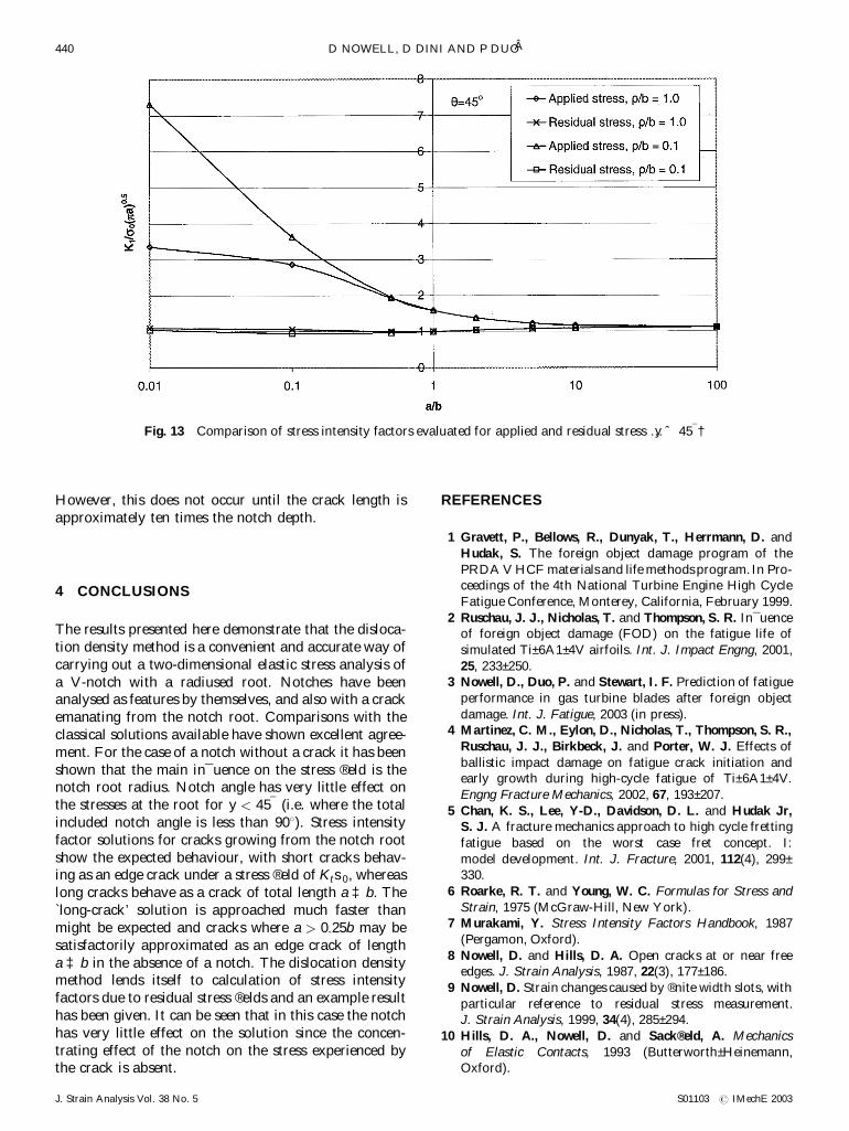
However, this does not occur until the crack length isapproximately ten times the notch depth.
4 CONCLUSIONS
The results presented here demonstrate that the disloca-tion density method is a convenient and accurate way ofcarrying out a two-dimensional elastic stress analysis ofa V-notch with a radiused root. Notches have beenanalysed as features by themselves, and also with a crackemanating from the notch root. Comparisons with theclassical solutions available have shown excellent agree-ment. For the case of a notch without a crack it has beenshown that the main in¯uence on the stress ®eld is thenotch root radius. Notch angle has very little effect onthe stresses at the root for y < 45¯ (i.e. where the totalincluded notch angle is less than 908). Stress intensityfactor solutions for cracks growing from the notch rootshow the expected behaviour, with short cracks behav-ing as an edge crack under a stress ®eld of Kts0, whereaslong cracks behave as a crack of total length a ‡ b. The`long-crack’ solution is approached much faster thanmight be expected and cracks where a > 0:25b may besatisfactorily approximated as an edge crack of lengtha ‡ b in the absence of a notch. The dislocation densitymethod lends itself to calculation of stress intensityfactors due to residual stress ®elds and an example resulthas been given. It can be seen that in this case the notchhas very little effect on the solution since the concen-trating effect of the notch on the stress experienced bythe crack is absent.
REFERENCES
1 Gravett, P., Bellows, R., Dunyak, T., Herrmann, D. and
Hudak, S. The foreign object damage program of the
PRDA V HCF materials and life methods program. In Pro-ceedings of the 4th National Turbine Engine High Cycle
Fatigue Conference, Monterey, California, February 1999.
2 Ruschau, J. J., Nicholas, T. and Thompson, S. R. In¯uenceof foreign object damage (FOD) on the fatigue life of
simulated Ti±6A1±4V airfoils. Int. J. Impact Engng, 2001,
25, 233±250.3 Nowell, D., Duo, P. and Stewart, I. F. Prediction of fatigue
performance in gas turbine blades after foreign object
damage. Int. J. Fatigue, 2003 (in press).4 Martinez, C. M., Eylon, D., Nicholas, T., Thompson, S. R.,
Ruschau, J. J., Birkbeck, J. and Porter, W. J. Effects of
ballistic impact damage on fatigue crack initiation andearly growth during high-cycle fatigue of Ti±6A1±4V.
Engng Fracture Mechanics, 2002, 67, 193±207.
5 Chan, K. S., Lee, Y-D., Davidson, D. L. and Hudak Jr,S. J. A fracture mechanics approach to high cycle fretting
fatigue based on the worst case fret concept. I:
model development. Int. J. Fracture, 2001, 112(4), 299±330.
6 Roarke, R. T. and Young, W. C. Formulas for Stress and
Strain, 1975 (McGraw-Hill, New York).7 Murakami, Y. Stress Intensity Factors Handbook, 1987
(Pergamon, Oxford).
8 Nowell, D. and Hills, D. A. Open cracks at or near freeedges. J. Strain Analysis, 1987, 22(3), 177±186.
9 Nowell, D. Strain changes caused by ®nite width slots, with
particular reference to residual stress measurement.J. Strain Analysis, 1999, 34(4), 285±294.
10 Hills, D. A., Nowell, D. and Sack®eld, A. Mechanics
of Elastic Contacts, 1993 (Butterworth±Heinemann,Oxford).
Fig. 13 Comparison of stress intensity factors evaluated for applied and residual stress …y ˆ 45¯†
D NOWELL, D DINI AND P DUOÂ440
J. Strain Analysis Vol. 38 No. 5 S01103 # IMechE 2003

11 Hills, D. A. and Nowell, D. Kinked cracks: ®nding stressintensity factors. In Applied Stress Analysis (Eds T. H.
Hyde and E. Ollerton), Proceedings of the Conference on
Applied Stress Analysis, University of Nottingham, 30±31August 1990, pp. 36±50 (Elsevier, Amsterdam).
12 Neuber, H. Theory of Notch Stresses, 1958 (Springer-
Verlag, Berlin).13 Glinka, G. and Newport, A. Universal features of elastic
notch-tip stress ®eld. Int. J. Fatigue, 1987, 9, 143±
150.14 Shin, C. S., Man, K. C. and Wang, C. M. A practical
method to estimate the stress concentration of notches. Int.
J. Fatigue, 1994, 16, 242±255.15 Lazzarin, P. and Tovo, R. A uni®ed approach to the
evaluation of linear elastic ®elds in the neighbourhood of
cracks and notches. Int. J. Fracture, 1996, 78, 3±19.
16 Filippi, S., Lazzarin, P. and Tovo, R. Development of someexplicit formulas useful to describe elastic stress ®elds
ahead of notches in plates. Int. J. Solids Structs, 2002, 39,
4543±4565.17 Creager, M. and Paris, P. C. Elastic ®eld equations for
blunt cracks with reference to stress corrosion cracking.
Int. J. Fracture Mechanics, 1967, 3, 247±252.18 Erdogan, F., Gupta, G. D. and Cook, T. S. Numerical
solution of singular integral equations. In Methods of
Analysis and Solutions of Crack Problems (Ed. G. C. Sih),1973, pp. 368±425 (Noordhoff, Leyden).
19 Peters, J. O., Boyce, B. L., Chen, X., McNaney, J. M.,
Hutchinson, J. W. and Ritchie, R. O. On the applicationof the Kitagawa±Takahashi diagram to foreign-object
damage and high cycle fatigue. Engng Fracture Mechanics,
2002, 69, 1425±1446.
STRESS ANALYSIS OF V-NOTCHES WITH AND WITHOUT CRACKS 441
S01103 # IMechE 2003 J. Strain Analysis Vol. 38 No. 5


![Special Members Beams with holes and notches...Special Members –Beams with holes and notches slide 13 Stress State –Beam with a hole –pure M Z Y X Axial Stresses y,+ [MPa] 8.0](https://img.pdfslide.net/doc/110x75/610788a81f2f843856363428/special-members-beams-with-holes-and-special-members-abeams-with-holes-and.jpg)


![Composites: Part Aftp.mm.bme.hu/~szeki/files/2012_cpa.pdf · dard methods to help the design of composite structures with cracks and notches [1,2]. ... to realize that the disks belonging](https://img.pdfslide.net/doc/110x75/5ab740747f8b9ad3038b64e8/composites-part-aftpmmbmehuszekifiles2012cpapdfdard-methods-to-help-the.jpg)