Embed Size (px)
Citation preview
NILESH MOHITE* et al. ISSN: 2250–3676
[IJESAT] INTERNATIONAL JOURNAL OF ENGINEERING SCIENCE & ADVANCED TECHNOLOGY Volume-2, Issue-6, 1663 – 1669
IJESAT | Nov-Dec 2012
Available online @ http://www.ijesat.org 1663
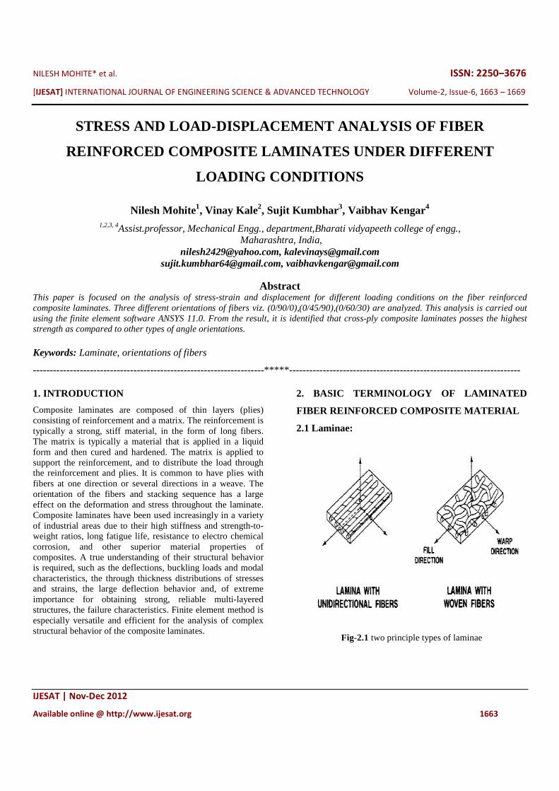
STRESS AND LOAD-DISPLACEMENT ANALYSIS OF FIBER
REINFORCED COMPOSITE LAMINATES UNDER DIFFERENT
LOADING CONDITIONS
Nilesh Mohite1, Vinay Kale2, Sujit Kumbhar3, Vaibhav Kengar4 1,2,3, 4Assist.professor, Mechanical Engg., department,Bharati vidyapeeth college of engg.,
Maharashtra, India, [email protected], [email protected]
[email protected], [email protected]
Abstract This paper is focused on the analysis of stress-strain and displacement for different loading conditions on the fiber reinforced composite laminates. Three different orientations of fibers viz. (0/90/0),(0/45/90),(0/60/30) are analyzed. This analysis is carried out using the finite element software ANSYS 11.0. From the result, it is identified that cross-ply composite laminates posses the highest strength as compared to other types of angle orientations. Keywords: Laminate, orientations of fibers
---------------------------------------------------------------------*****---------------------------- -----------------------------------------
1. INTRODUCTION
Composite laminates are composed of thin layers (plies) consisting of reinforcement and a matrix. The reinforcement is typically a strong, stiff material, in the form of long fibers. The matrix is typically a material that is applied in a liquid form and then cured and hardened. The matrix is applied to support the reinforcement, and to distribute the load through the reinforcement and plies. It is common to have plies with fibers at one direction or several directions in a weave. The orientation of the fibers and stacking sequence has a large effect on the deformation and stress throughout the laminate. Composite laminates have been used increasingly in a variety of industrial areas due to their high stiffness and strength-to-weight ratios, long fatigue life, resistance to electro chemical corrosion, and other superior material properties of composites. A true understanding of their structural behavior is required, such as the deflections, buckling loads and modal characteristics, the through thickness distributions of stresses and strains, the large deflection behavior and, of extreme importance for obtaining strong, reliable multi-layered structures, the failure characteristics. Finite element method is especially versatile and efficient for the analysis of complex structural behavior of the composite laminates.
2. BASIC TERMINOLOGY OF LAMINATED
FIBER REINFORCED COMPOSITE MATERIAL
2.1 Laminae:
Fig-2.1 two principle types of laminae
NILESH MOHITE* et al. ISSN: 2250–3676
[IJESAT] INTERNATIONAL JOURNAL OF ENGINEERING SCIENCE & ADVANCED TECHNOLOGY Volume-2, Issue-6, 1663 – 1669
IJESAT | Nov-Dec 2012
Available online @ http://www.ijesat.org 1664
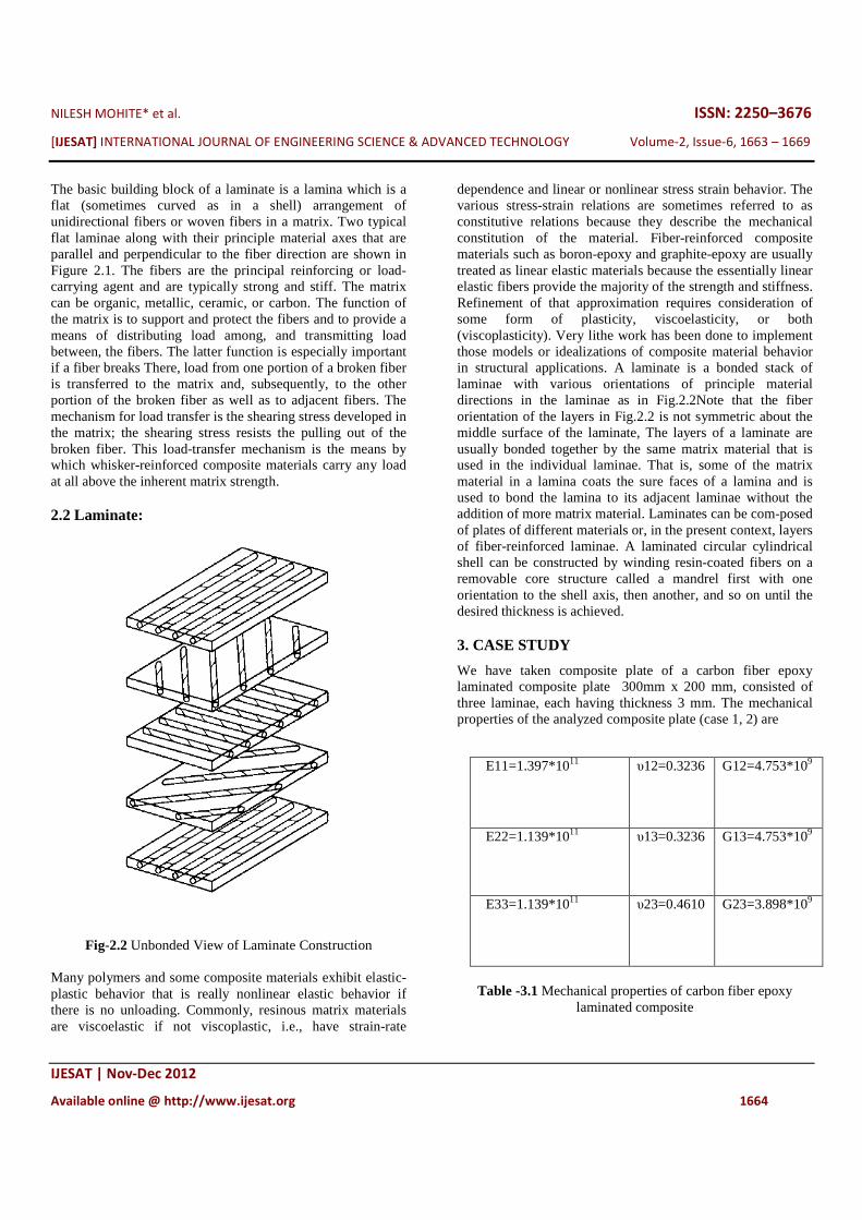
The basic building block of a laminate is a lamina which is a flat (sometimes curved as in a shell) arrangement of unidirectional fibers or woven fibers in a matrix. Two typical flat laminae along with their principle material axes that are parallel and perpendicular to the fiber direction are shown in Figure 2.1. The fibers are the principal reinforcing or load-carrying agent and are typically strong and stiff. The matrix can be organic, metallic, ceramic, or carbon. The function of the matrix is to support and protect the fibers and to provide a means of distributing load among, and transmitting load between, the fibers. The latter function is especially important if a fiber breaks There, load from one portion of a broken fiber is transferred to the matrix and, subsequently, to the other portion of the broken fiber as well as to adjacent fibers. The mechanism for load transfer is the shearing stress developed in the matrix; the shearing stress resists the pulling out of the broken fiber. This load-transfer mechanism is the means by which whisker-reinforced composite materials carry any load at all above the inherent matrix strength. 2.2 Laminate:
Fig-2.2 Unbonded View of Laminate Construction
Many polymers and some composite materials exhibit elastic-plastic behavior that is really nonlinear elastic behavior if there is no unloading. Commonly, resinous matrix materials are viscoelastic if not viscoplastic, i.e., have strain-rate
dependence and linear or nonlinear stress strain behavior. The various stress-strain relations are sometimes referred to as constitutive relations because they describe the mechanical constitution of the material. Fiber-reinforced composite materials such as boron-epoxy and graphite-epoxy are usually treated as linear elastic materials because the essentially linear elastic fibers provide the majority of the strength and stiffness. Refinement of that approximation requires consideration of some form of plasticity, viscoelasticity, or both (viscoplasticity). Very lithe work has been done to implement those models or idealizations of composite material behavior in structural applications. A laminate is a bonded stack of laminae with various orientations of principle material directions in the laminae as in Fig.2.2Note that the fiber orientation of the layers in Fig.2.2 is not symmetric about the middle surface of the laminate, The layers of a laminate are usually bonded together by the same matrix material that is used in the individual laminae. That is, some of the matrix material in a lamina coats the sure faces of a lamina and is used to bond the lamina to its adjacent laminae without the addition of more matrix material. Laminates can be com-posed of plates of different materials or, in the present context, layers of fiber-reinforced laminae. A laminated circular cylindrical shell can be constructed by winding resin-coated fibers on a removable core structure called a mandrel first with one orientation to the shell axis, then another, and so on until the desired thickness is achieved. 3. CASE STUDY
We have taken composite plate of a carbon fiber epoxy laminated composite plate 300mm x 200 mm, consisted of three laminae, each having thickness 3 mm. The mechanical properties of the analyzed composite plate (case 1, 2) are
Table -3.1 Mechanical properties of carbon fiber epoxy
laminated composite
E11=1.397*1011
υ12=0.3236 G12=4.753*109
E22=1.139*1011
υ13=0.3236 G13=4.753*109
E33=1.139*1011
υ23=0.4610 G23=3.898*109
NILESH MOHITE* et al. ISSN: 2250–3676
[IJESAT] INTERNATIONAL JOURNAL OF ENGINEERING SCIENCE & ADVANCED TECHNOLOGY Volume-2, Issue-6, 1663 – 1669
IJESAT | Nov-Dec 2012
Available online @ http://www.ijesat.org 1665
3.1 Type of element used
SHELL181
Fig-3.1 Geometry of Shell 181 element
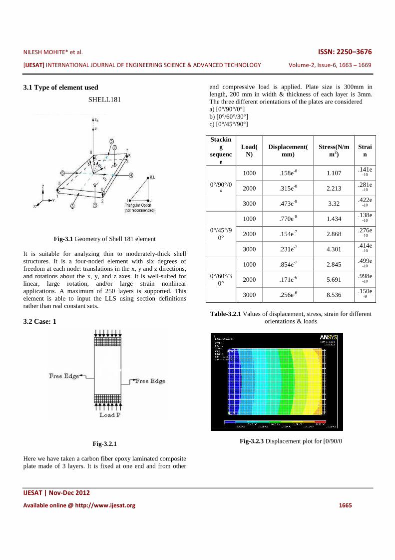
It is suitable for analyzing thin to moderately-thick shell structures. It is a four-noded element with six degrees of freedom at each node: translations in the x, y and z directions, and rotations about the x, y, and z axes. It is well-suited for linear, large rotation, and/or large strain nonlinear applications. A maximum of 250 layers is supported. This element is able to input the LLS using section definitions rather than real constant sets. 3.2 Case: 1
Fig-3.2.1
Here we have taken a carbon fiber epoxy laminated composite plate made of 3 layers. It is fixed at one end and from other
end compressive load is applied. Plate size is 300mm in length, 200 mm in width & thickness of each layer is 3mm. The three different orientations of the plates are considered a) [0°/90°/0°] b) [0°/60°/30°] c) [0°/45°/90°] Stackin
g sequenc
e
Load(N)
Displacement(mm)
Stress(N/mm2)
Strain
0°/90°/0°
1000 .158e-8 1.107 .141e
-10
2000 .315e-8 2.213 .281e
-10
3000 .473e-8 3.32 .422e
-10
0°/45°/90°
1000 .770e-8 1.434 .138e
-10
2000 .154e-7 2.868 .276e
-10
3000 .231e-7 4.301 .414e
-10
0°/60°/30°
1000 .854e-7 2.845 .499e
-10
2000 .171e-6 5.691 .998e-10
3000 .256e-6 8.536 .150e
-9
Table-3.2.1 Values of displacement, stress, strain for different
orientations & loads
Fig-3.2.3 Displacement plot for [0/90/0
NILESH MOHITE* et al.
[IJESAT] INTERNATIONAL JOURNAL OF ENGINEERING SCIENCE & ADVANCED TECHNOLOGY
IJESAT | Nov-Dec 2012
Available online @ http://www.ijesat.org
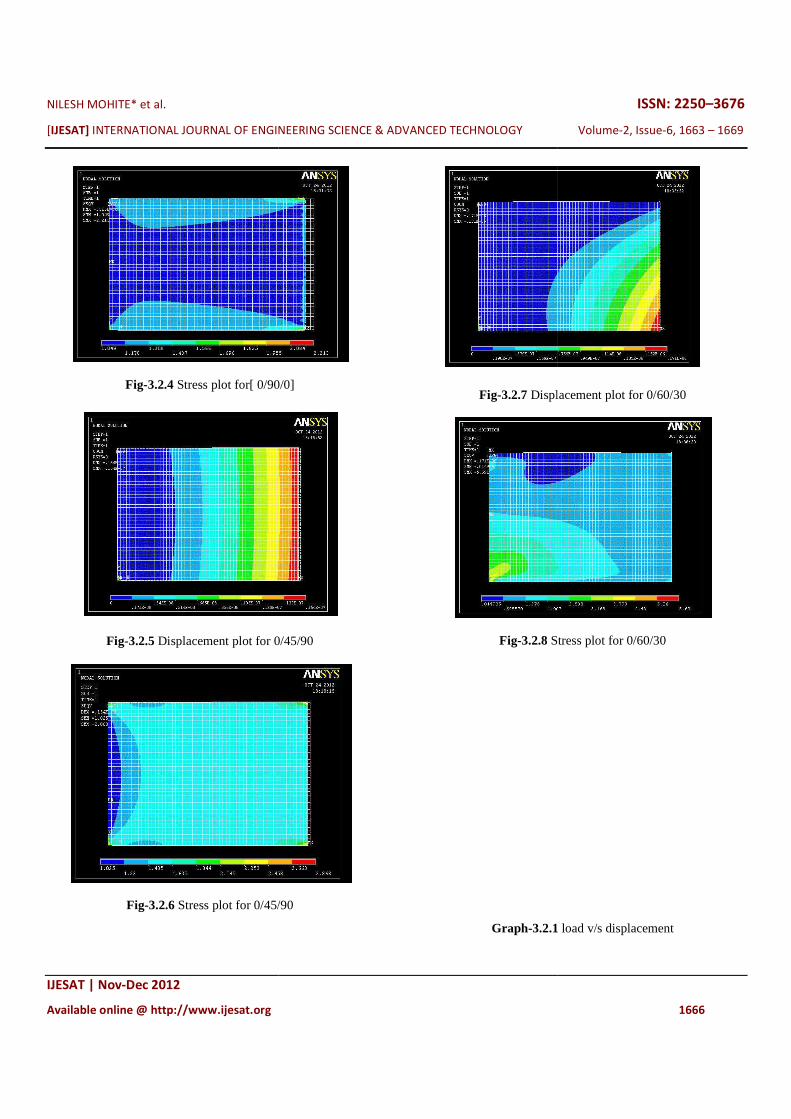
Fig-3.2.4 Stress plot for[ 0/90/0]
Fig-3.2.5 Displacement plot for 0/45/90
Fig-3.2.6 Stress plot for 0/45/90
INTERNATIONAL JOURNAL OF ENGINEERING SCIENCE & ADVANCED TECHNOLOGY
Available online @ http://www.ijesat.org
plot for[ 0/90/0]
Displacement plot for 0/45/90
Stress plot for 0/45/90
Fig-3.2.7 Displacement plot for 0/60/30
Fig-3.2.8 Stress plot for 0/60/30
Graph-3.2.1
ISSN: 2250–3676
INTERNATIONAL JOURNAL OF ENGINEERING SCIENCE & ADVANCED TECHNOLOGY Volume-2, Issue-6, 1663 – 1669
1666
Displacement plot for 0/60/30
Stress plot for 0/60/30
1 load v/s displacement
NILESH MOHITE* et al.
[IJESAT] INTERNATIONAL JOURNAL OF ENGINEERING SCIENCE & ADVANCED TECHNOLOGY
IJESAT | Nov-Dec 2012
Available online @ http://www.ijesat.org
Graph-3.2.2 stress v/s strain
3.3 Case 2:
Fig.3.3.1
In this case, plate with same properties and dimensions is taken. It is fixed at both ends and a concentrated load is applied at the center. The plate is analyzed under different loading conditions.
Stacking sequence
Load(N)
Displacement(mm)
Stress(N/
0°/90°/0° 1000 .105e-6
2000 .210e-6
INTERNATIONAL JOURNAL OF ENGINEERING SCIENCE & ADVANCED TECHNOLOGY
Available online @ http://www.ijesat.org
stress v/s strain
In this case, plate with same properties and dimensions is taken. It is fixed at both ends and a concentrated load is applied at the center. The plate is analyzed under different
Stress(N/mm2)
Strain
15.739 .118e-
9
31.478 .237e-
9
3000
0°/45°/90°
1000
2000
3000
0°/60°/30°
1000
2000
3000
Table 3.3.1 Values of displacement, stress, strain for different orientations & loads
Fig-3.3.2Displacement plot for 0/90/0
Fig-3.3.3 Stress plot
ISSN: 2250–3676
INTERNATIONAL JOURNAL OF ENGINEERING SCIENCE & ADVANCED TECHNOLOGY Volume-2, Issue-6, 1663 – 1669
1667
.314e-6 47.217 .355e-
9
.116e-6 16.66 .143e-
9
.231e-6 33.32 .285e-
9
.347e-6 49.981 .428e-
9
.146e-6 21 .211e-
9
.292e-6 42.001 .422e-
9
.439e-6 63.001 .633e-
9
Values of displacement, stress, strain for different
orientations & loads
Displacement plot for 0/90/0
Stress plot for 0/90/0

NILESH MOHITE* et al.
[IJESAT] INTERNATIONAL JOURNAL OF ENGINEERING SCIENCE & ADVANCED TECHNOLOGY
IJESAT | Nov-Dec 2012
Available online @ http://www.ijesat.org
Fig-3.3.4 Displacement plot for 0/45/90
Fig-3.3.5 Stress plot for 0/45/90
Fig-3.3.6 Displacement plot for 0/60/30
INTERNATIONAL JOURNAL OF ENGINEERING SCIENCE & ADVANCED TECHNOLOGY
Available online @ http://www.ijesat.org
ent plot for 0/45/90
Stress plot for 0/45/90
Displacement plot for 0/60/30
Fig-3.3.7 Stress plot for 0/60/30
Graph-3.3.1
Graph-3.3.2
ISSN: 2250–3676
INTERNATIONAL JOURNAL OF ENGINEERING SCIENCE & ADVANCED TECHNOLOGY Volume-2, Issue-6, 1663 – 1669
1668
Stress plot for 0/60/30
3.3.1 load v/s displacement
3.3.2 Stress v/s strain
NILESH MOHITE* et al. ISSN: 2250–3676
[IJESAT] INTERNATIONAL JOURNAL OF ENGINEERING SCIENCE & ADVANCED TECHNOLOGY Volume-2, Issue-6, 1663 – 1669
IJESAT | Nov-Dec 2012
Available online @ http://www.ijesat.org 1669
CONCLUSION:
1. In a composite material, the fibers are the main constituents which are responsible for the strength of the composite. 2. In this study, the different fiber orientation like [0°/90°/0°] [0°/60°/30°] and [90°/45°/0°] are analyzed under different loading conditions. 3. Out of these orientations, it is found that the [0°/90°/0°] configuration is the best and has the maximum load bearing capacity and strength than the other orientations.i.e.the cross plies have maximum load carrying capacity as compared to angular plies. REFERENCES:
1. Mechanics Of Composite Materials (Materials Science & Engineering Series) By Robert Jones 2. Manoharan R. , Jeevanantham A. K.2011 Stress And Load-Displacement Analysis Of Fiberreinforced Composite
Laminates With A Circular Hole Under Compressive Load:Vol. 6, No. 4, April 2011 3. Nagendra Singh Gaira, Linear Buckling Analysis Of Laminated Composite Plate Volume-2, Issue-4, 886 – 891 Aug2012 4. Robin Olsson, Jonas Iwarsson. 2003. Experiments And Analysis Of Laminates With Artificial Damage. Composites Science And Technology. 63: 199-201. 5. Hakim S. Sultan Aljibori, W.P. Chong. 2009. Load Displacement Behavior Of Glass Fiber/Epoxy Composite Plates With Circular Cut-Outs Subjected To Compressive Load. Materials And Design. 31: 466-474. 6. De Freitas M, Reis L. 1998. Failure Mechanisms On Composite Specimens Subjected To Compression After Impact. J. Compos Structure. 42: 365-366. 7. Takeda T, Takano S, Shindo Y, Narita F. 2005.Deformation And Progressive Failure Behavior Of Woven Fabric-Reinforced Glass/Epoxy Composite Laminates Under Tensile Loading At Cryogenic Temperatures. J. Compos Sci Technol. 65:1691-1702


![GRID INTEGRATION OF PERMANENT MAGNET SYNCHRONOUS GENERATOR ...ijesat.org/Volumes/2015_Vol_05_Iss_03/IJESAT_2015_05_03_06.pdf · R Elamparithi* et al. ISSN: 2250-3676 [IJESAT] [International](https://img.pdfslide.net/doc/110x75/5b540f6c7f8b9a5a578cc44c/grid-integration-of-permanent-magnet-synchronous-generator-r-elamparithi.jpg)