Embed Size (px)
Citation preview
Proceedings of the International Association for Shell and Spatial Structures (IASS) Symposium 2009, Valencia Evolution and Trends in Design, Analysis and Construction of Shell and Spatial Structures
28 September – 2 October 2009, Universidad Politecnica de Valencia, Spain Alberto DOMINGO and Carlos LAZARO (eds.)
Stress distribution at the load introduction point of glass plates subjected to compression
Danijel MOCIBOB*, Jan BELISa, Michel CRISINELb, Jean-Paul LEBETb
*IGH Institute,
J. Rakuse 1, 10000 Zagreb, Croatia [email protected]
a Ghent University, LMO, Ghent, Belgium
b EPFL, ICOM, Lausanne, Switzerland [email protected]
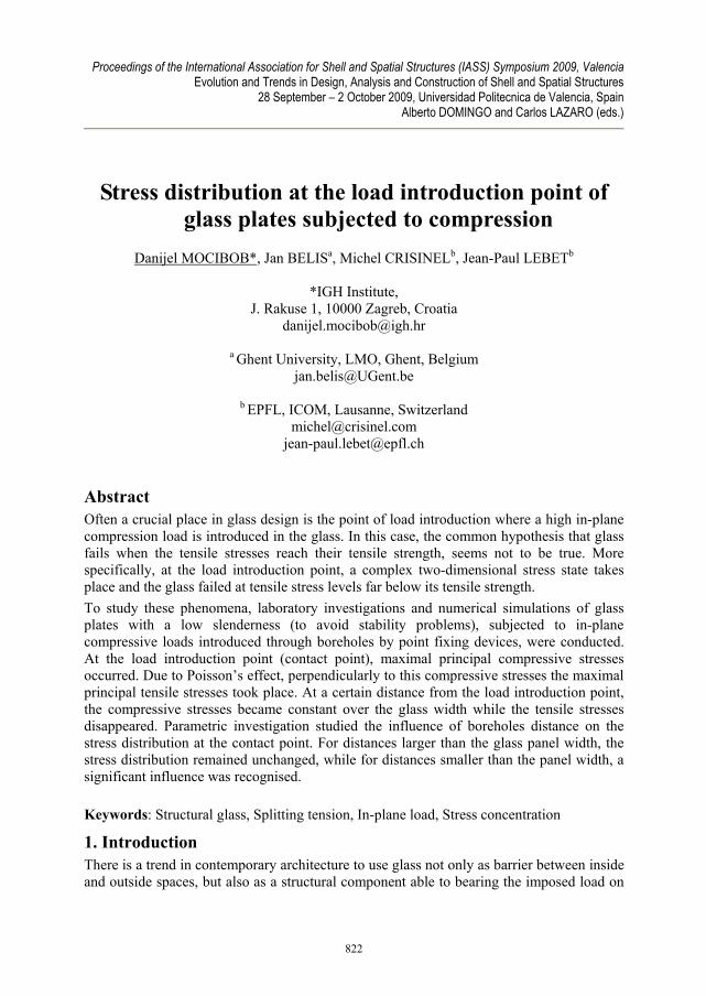
Abstract Often a crucial place in glass design is the point of load introduction where a high in-plane compression load is introduced in the glass. In this case, the common hypothesis that glass fails when the tensile stresses reach their tensile strength, seems not to be true. More specifically, at the load introduction point, a complex two-dimensional stress state takes place and the glass failed at tensile stress levels far below its tensile strength. To study these phenomena, laboratory investigations and numerical simulations of glass plates with a low slenderness (to avoid stability problems), subjected to in-plane compressive loads introduced through boreholes by point fixing devices, were conducted. At the load introduction point (contact point), maximal principal compressive stresses occurred. Due to Poisson’s effect, perpendicularly to this compressive stresses the maximal principal tensile stresses took place. At a certain distance from the load introduction point, the compressive stresses became constant over the glass width while the tensile stresses disappeared. Parametric investigation studied the influence of boreholes distance on the stress distribution at the contact point. For distances larger than the glass panel width, the stress distribution remained unchanged, while for distances smaller than the panel width, a significant influence was recognised. Keywords: Structural glass, Splitting tension, In-plane load, Stress concentration
1. Introduction There is a trend in contemporary architecture to use glass not only as barrier between inside and outside spaces, but also as a structural component able to bearing the imposed load on
822
Proceedings of the International Association for Shell and Spatial Structures (IASS) Symposium 2009, Valencia Evolution and Trends in Design, Analysis and Construction of Shell and Spatial Structures
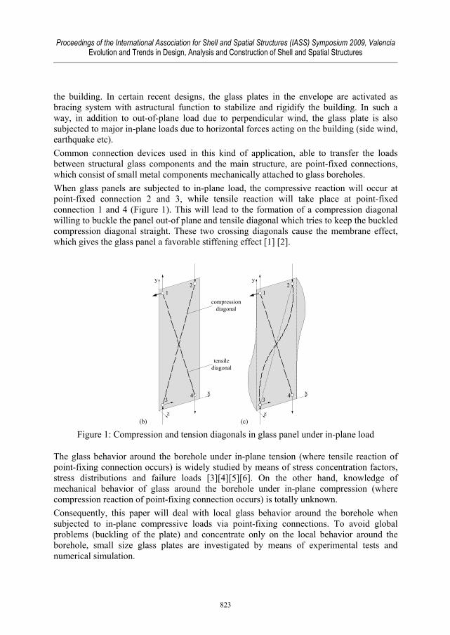
the building. In certain recent designs, the glass plates in the envelope are activated as bracing system with astructural function to stabilize and rigidify the building. In such a way, in addition to out-of-plane load due to perpendicular wind, the glass plate is also subjected to major in-plane loads due to horizontal forces acting on the building (side wind, earthquake etc). Common connection devices used in this kind of application, able to transfer the loads between structural glass components and the main structure, are point-fixed connections, which consist of small metal components mechanically attached to glass boreholes. When glass panels are subjected to in-plane load, the compressive reaction will occur at point-fixed connection 2 and 3, while tensile reaction will take place at point-fixed connection 1 and 4 (Figure 1). This will lead to the formation of a compression diagonal willing to buckle the panel out-of plane and tensile diagonal which tries to keep the buckled compression diagonal straight. These two crossing diagonals cause the membrane effect, which gives the glass panel a favorable stiffening effect [1] [2].
x
z
x
y
z
12
34
y
12
34
compressiondiagonal
tensilediagonal
(b) (c) Figure 1: Compression and tension diagonals in glass panel under in-plane load
The glass behavior around the borehole under in-plane tension (where tensile reaction of point-fixing connection occurs) is widely studied by means of stress concentration factors, stress distributions and failure loads [3][4][5][6]. On the other hand, knowledge of mechanical behavior of glass around the borehole under in-plane compression (where compression reaction of point-fixing connection occurs) is totally unknown. Consequently, this paper will deal with local glass behavior around the borehole when subjected to in-plane compressive loads via point-fixing connections. To avoid global problems (buckling of the plate) and concentrate only on the local behavior around the borehole, small size glass plates are investigated by means of experimental tests and numerical simulation.
823
Proceedings of the International Association for Shell and Spatial Structures (IASS) Symposium 2009, Valencia Evolution and Trends in Design, Analysis and Construction of Shell and Spatial Structures
2. Experimental investigation
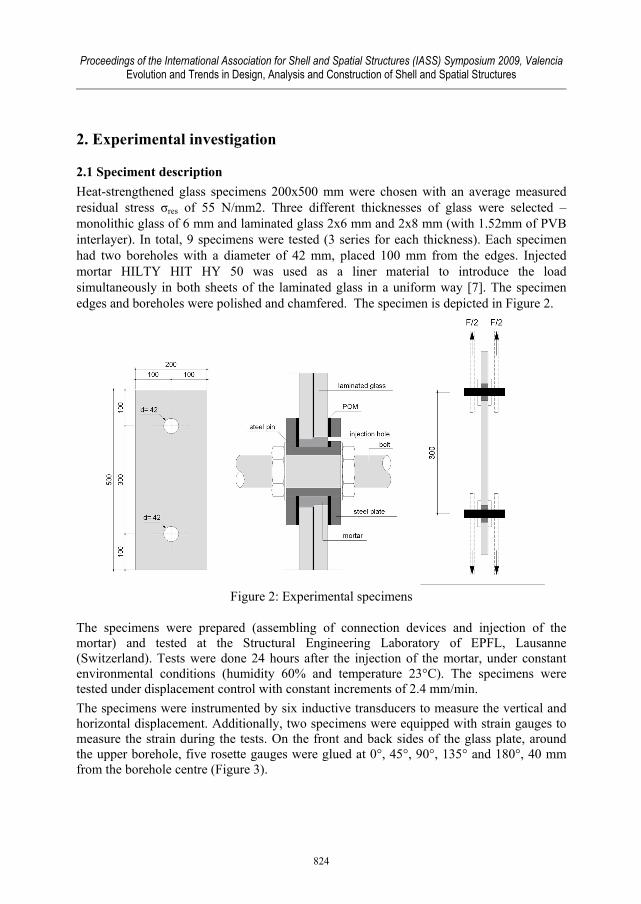
2.1 Speciment description Heat-strengthened glass specimens 200x500 mm were chosen with an average measured residual stress σres of 55 N/mm2. Three different thicknesses of glass were selected – monolithic glass of 6 mm and laminated glass 2x6 mm and 2x8 mm (with 1.52mm of PVB interlayer). In total, 9 specimens were tested (3 series for each thickness). Each specimen had two boreholes with a diameter of 42 mm, placed 100 mm from the edges. Injected mortar HILTY HIT HY 50 was used as a liner material to introduce the load simultaneously in both sheets of the laminated glass in a uniform way [7]. The specimen edges and boreholes were polished and chamfered. The specimen is depicted in Figure 2.
Figure 2: Experimental specimens
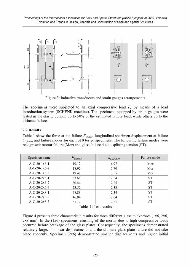
The specimens were prepared (assembling of connection devices and injection of the mortar) and tested at the Structural Engineering Laboratory of EPFL, Lausanne (Switzerland). Tests were done 24 hours after the injection of the mortar, under constant environmental conditions (humidity 60% and temperature 23°C). The specimens were tested under displacement control with constant increments of 2.4 mm/min. The specimens were instrumented by six inductive transducers to measure the vertical and horizontal displacement. Additionally, two specimens were equipped with strain gauges to measure the strain during the tests. On the front and back sides of the glass plate, around the upper borehole, five rosette gauges were glued at 0°, 45°, 90°, 135° and 180°, 40 mm from the borehole centre (Figure 3).
824
Proceedings of the International Association for Shell and Spatial Structures (IASS) Symposium 2009, Valencia Evolution and Trends in Design, Analysis and Construction of Shell and Spatial Structures
VVV
H
H
H
H
H
VV
100
300
100
500
V
H
123 123
1
2
3
1
2
3
j10 j20
180°
0°
j11j12
j13
j14j15
j21j22
j23
j24j25
180°
0°
Figure 3: Inductive transducers and strain gauges arrangements
The specimens were subjected to an axial compressive load Fc by means of a load introduction system (SCHENK machine). The specimens equipped by strain gauges were tested in the elastic domain up to 50% of the estimated failure load, while others up to the ultimate failure.
2.2 Results Table 1 show the force at the failure Ffailure, longitudinal specimen displacement at failure δL,failure and failure modes for each of 9 tested specimens. The following failure modes were recognised: mortar failure (Mor) and glass failure due to splitting tension (ST).
Specimen name Ffailure δL,failure Failure mode
A-C-20-1x6-1 19.12 6.97 Mor A-C-20-1x6-2 18.92 5.70 Mor A-C-20-1x6-3 19.48 7.55 Mor A-C-20-2x6-1 33.68 2.54 ST A-C-20-2x6-2 30.44 2.25 ST A-C-20-2x6-3 23.52 2.33 ST A-C-20-2x8-1 48.88 2.34 ST A-C-20-2x8-2 46.04 2.64 ST A-C-20-2x8-3 51.12 2.51 ST
Table 1: Test results
Figure 4 presents three characteristic results for three different glass thicknesses (1x6, 2x6, 2x8 mm). In the (1x6) specimens, crushing of the mortar due to high compressive loads occurred before breakage of the glass plates. Consequently, the specimens demonstrated relatively large, nonlinear displacements and the ultimate glass plate failure did not take place suddenly. Specimen (2x6) demonstrated smaller displacements and higher initial
825
Proceedings of the International Association for Shell and Spatial Structures (IASS) Symposium 2009, Valencia Evolution and Trends in Design, Analysis and Construction of Shell and Spatial Structures
breakage loads, although it did never reach twice the level of the (1x6) failure loads. Again, the nonlinear load-displacement paths, which are probably caused by deformation of the injected mortar, can be recognized. Specimen (2x8) demonstrated the highest failure loads and the smallest displacements.
0
10
20
30
40
50
60
0 2 4 6 8 10
Displacement [mm]
Forc
e [k
N]
A-C-20-1X6-1A-C-20-2X6-1A-C-20-2X8-1
Figure 4 - compression and tension diagonals in glass panel under in-plane load
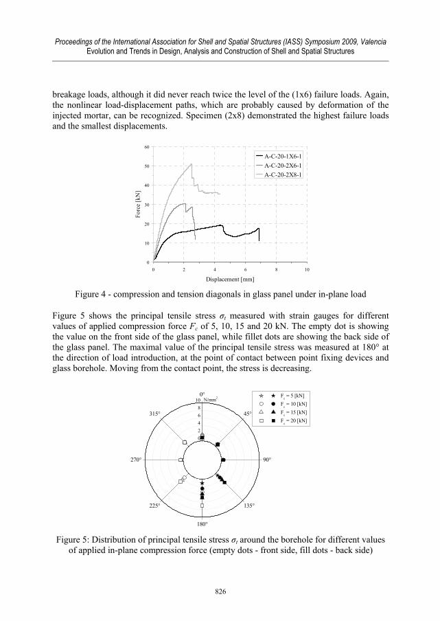
Figure 5 shows the principal tensile stress σt measured with strain gauges for different values of applied compression force Fc of 5, 10, 15 and 20 kN. The empty dot is showing the value on the front side of the glass panel, while fillet dots are showing the back side of the glass panel. The maximal value of the principal tensile stress was measured at 180° at the direction of load introduction, at the point of contact between point fixing devices and glass borehole. Moving from the contact point, the stress is decreasing.
-4-202468
100°
45°
90°
135°
180°
225°
270°
315°
-4-202468
10
Fc = 5 [kN] F
c = 10 [kN]
Fc = 15 [kN] F
c = 20 [kN]
N/mm2
Figure 5: Distribution of principal tensile stress σt around the borehole for different values
of applied in-plane compression force (empty dots - front side, fill dots - back side)
826
Proceedings of the International Association for Shell and Spatial Structures (IASS) Symposium 2009, Valencia Evolution and Trends in Design, Analysis and Construction of Shell and Spatial Structures
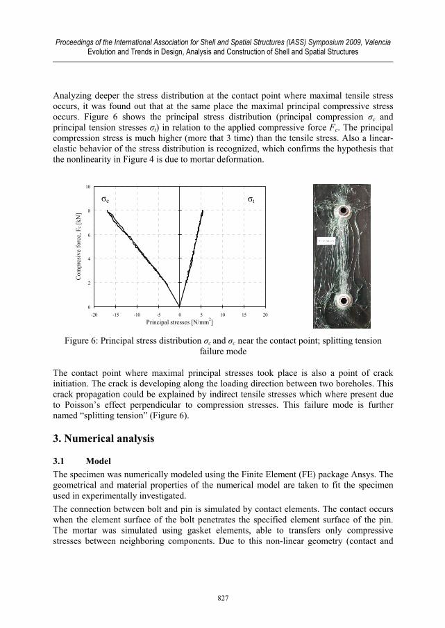
Analyzing deeper the stress distribution at the contact point where maximal tensile stress occurs, it was found out that at the same place the maximal principal compressive stress occurs. Figure 6 shows the principal stress distribution (principal compression σc and principal tension stresses σt) in relation to the applied compressive force Fc. The principal compression stress is much higher (more that 3 time) than the tensile stress. Also a linear-elastic behavior of the stress distribution is recognized, which confirms the hypothesis that the nonlinearity in Figure 4 is due to mortar deformation.
0
2
4
6
8
10
-20 -15 -10 -5 0 5 10 15 20Principal stresses [N/mm2]
Com
pres
ive
forc
e, F
c [kN
]
Figure 6: Principal stress distribution σc and σc near the contact point; splitting tension
failure mode
The contact point where maximal principal stresses took place is also a point of crack initiation. The crack is developing along the loading direction between two boreholes. This crack propagation could be explained by indirect tensile stresses which where present due to Poisson’s effect perpendicular to compression stresses. This failure mode is further named “splitting tension” (Figure 6).
3. Numerical analysis
3.1 Model The specimen was numerically modeled using the Finite Element (FE) package Ansys. The geometrical and material properties of the numerical model are taken to fit the specimen used in experimentally investigated. The connection between bolt and pin is simulated by contact elements. The contact occurs when the element surface of the bolt penetrates the specified element surface of the pin. The mortar was simulated using gasket elements, able to transfers only compressive stresses between neighboring components. Due to this non-linear geometry (contact and
σt σc
827
Proceedings of the International Association for Shell and Spatial Structures (IASS) Symposium 2009, Valencia Evolution and Trends in Design, Analysis and Construction of Shell and Spatial Structures
gasket) and non-linear material (elasto-plastic material law for mortar and steel), a nonlinear analysis was performed using the Neuton-Rapson method. The numerical model was calibrated by comparing the results obtained bye the FE model and stresses obtained by strain gauge measurements during the experimental investigation.
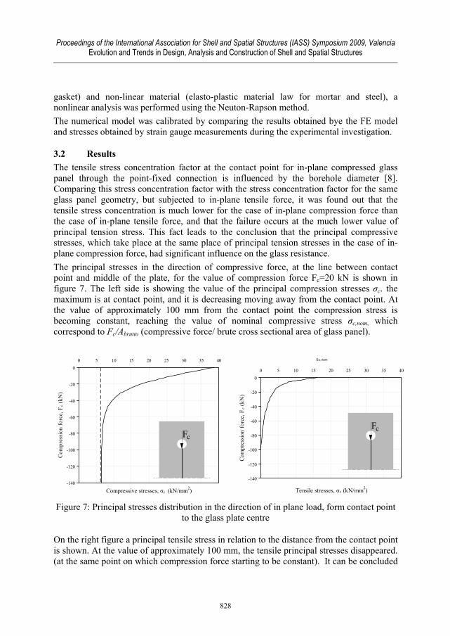
3.2 Results The tensile stress concentration factor at the contact point for in-plane compressed glass panel through the point-fixed connection is influenced by the borehole diameter [8]. Comparing this stress concentration factor with the stress concentration factor for the same glass panel geometry, but subjected to in-plane tensile force, it was found out that the tensile stress concentration is much lower for the case of in-plane compression force than the case of in-plane tensile force, and that the failure occurs at the much lower value of principal tension stress. This fact leads to the conclusion that the principal compressive stresses, which take place at the same place of principal tension stresses in the case of in-plane compression force, had significant influence on the glass resistance. The principal stresses in the direction of compressive force, at the line between contact point and middle of the plate, for the value of compression force Fc=20 kN is shown in figure 7. The left side is showing the value of the principal compression stresses σc. the maximum is at contact point, and it is decreasing moving away from the contact point. At the value of approximately 100 mm from the contact point the compression stress is becoming constant, reaching the value of nominal compressive stress σc,nom, which correspond to Fc/Abrutto (compressive force/ brute cross sectional area of glass panel).
-140
-120
-100
-80
-60
-40
-20
00 5 10 15 20 25 30 35 40
Compressive stresses, σc (kN/mm2)
Com
pres
sion
forc
e, F
c (kN
)
Sc,nom
-140
-120
-100
-80
-60
-40
-20
00 5 10 15 20 25 30 35 40
Tensile stresses, σt (kN/mm2)
Com
pres
sion
forc
e, F
c (kN
)
Figure 7: Principal stresses distribution in the direction of in plane load, form contact point
to the glass plate centre
On the right figure a principal tensile stress in relation to the distance from the contact point is shown. At the value of approximately 100 mm, the tensile principal stresses disappeared. (at the same point on which compression force starting to be constant). It can be concluded
Fc
Fc
828
Proceedings of the International Association for Shell and Spatial Structures (IASS) Symposium 2009, Valencia Evolution and Trends in Design, Analysis and Construction of Shell and Spatial Structures
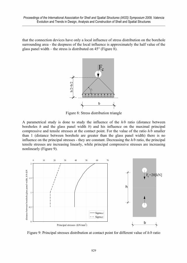
that the connection devices have only a local influence of stress distribution on the borehole surrounding area - the deepness of the local influence is approximately the half value of the glass panel width – the stress is distributed on 45° (Figure 8).
Fc
45°h/
2=b/
2
b
Figure 8: Stress distribution triangle
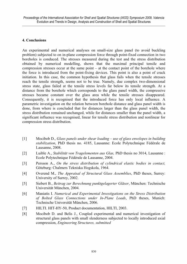
A parametrical study is done to study the influence of the h/b ratio (distance between boreholes h and the glass panel width b) and his influence on the maximal principal compressive and tensile stresses at the contact point. For the value of the ratio h/b smaller than 1 (distance between borehole are greater than the glass panel width) there is no influence on the principal stresses - they are constant. Decreasing the h/b ratio, the principal tensile stresses are increasing linearly, while principal compressive stresses are increasing nonlinearly (Figure 9).
0
0.5
1
1.5
20 10 20 30 40 50 60 70
Principal stresses (kN/mm2)
dist
ance
bet
wee
n bo
reho
le/g
lass
pan
el w
idth
, h/b
(kN
)
Sigma,cSigma,t
F =20[kN]c
h
b
Figure 9: Principal stresses distribution at contact point for different value of h/b ratio
829
Proceedings of the International Association for Shell and Spatial Structures (IASS) Symposium 2009, Valencia Evolution and Trends in Design, Analysis and Construction of Shell and Spatial Structures
4. Conclusions
An experimental and numerical analyses on small-size glass panel (to avoid buckling problem) subjected to on in-plane compression force through point-fixed connection in two boreholes is conduced. The stresses measured during the test and the stress distribution obtained by numerical modelling, shows that the maximal principal tensile and compression stresses occur at the same point – at the contact point of the borehole where the force is introduced from the point-fixing devices. This point is also a point of crack initiation. In this case, the common hypothesis that glass fails when the tensile stresses reach the tensile strength, seems not to be true. Namely, due complex two-dimensional stress state, glass failed at the tensile stress levels far below its tensile strength. At a distance from the borehole which corresponds to the glass panel width, the compressive stresses became constant over the glass area while the tensile stresses disappeared. Consequently, it is recognised that the introduced force has only local influence. A parametric investigation on the relation between borehole distance and glass panel width is done, from where is concluded that for distances larger than the glass panel width, the stress distribution remained unchanged, while for distances smaller than the panel width, a significant influence was recognised, linear for tensile stress distribution and nonlinear for compression stress distribution. [1] Mocibob D., Glass panels under shear loading – use of glass envelopes in building
stabilization, PhD thesis no. 4185, Lausanne: Ecole Polytechnique Fédérale de Lausanne, 2008.
[2] Luible A., Stabilität von Tragelementen aus Glas, PhD thesis no 3014, Lausanne : Ecole Polytechnique Fédérale de Lausanne, 2004.
[3] Persson A., On the stress distribution of cylindrical elastic bodies in contact, Göteburg: Chalmers Tekniska Hogskola, 1964.
[4] Overend M., The Appraisal of Structural Glass Assemblies, PhD theses, Surrey: University of Surrey, 2002.
[5] Siebert B., Beitrag zur Berechnung punktgelagerter Gläser, München: Technische Universität München, 2004.
[6] Maniatis I. Numerical and Experimental Investigations on the Stress Distribution of Bolted Glass Connections under In-Plane Loads, PhD theses, Munich: Technische Universität München, 2006.
[7] HILTI. HIT-HY-50, Product documentation, HILTI, 2003. [8] Mocibob D. and Belis J., Coupled experimental and numerical investigation of
structural glass panels with small slenderness subjected to locally introduced axial compression, Engineering Structures, submitted
830