Embed Size (px)
Citation preview

INSTRUCTION SHEET
I N D U S T R I A L E Q U I P M E N T & C O N T R O L P T Y . L T D .6 1 - 6 5 M c C l u r e S t . T h o r n b u r y . 3 0 7 1 M e l b o u r n e . A u s t r a l i a
T e l : 6 1 ( 0 ) 3 9 4 9 7 2 5 5 5 F a x : 6 1 ( 0 ) 3 9 4 9 7 2 1 6 6l b 3 8 0 8 - 0 0 1 . d o c 1 6 - J a n - 0 6
1
STROBOSCOPE, XENON - digital
LB3808-001 Standard model ‘XE’ LB3809-001 Advanced model ‘XE-H’DESCRIPTION:
The unique IEC Digital Xenon Stroboscope is specially designed for the mechanical engineeror consultant and for student use in the classroom. The bright flashing light is pointed at adevice in motion and, regardless of the type of motion, when the visible image appears to bestationary, the exact speed of the motion is displayed on the digital display. Sometimes,rather than measuring the speed of a moving object, only the visual examination of the‘Frozen’ Image is required. The large reflector ensures this feature is effective.
The instrument is microprocessor controlled and is crystal locked. The accuracy is exact andthe stability is absolute for the life of the instrument. Calibration controls are not required.
LB3808-001 standard model “XE”
Physical size: 170x150x150mm LxWxH Weight: 1.7 kg
FEATURES:
The large 150mm diameter reflector provides a bright flash that covers a wide area. Theflash intensity automatically adjusts to provide the best brightness as the flash rate ischanged. Range: 1.000Hz to 300.0Hz (60.00RPM to 18,000RPM).
All controls are press by button and the memory feature ensures that when the instrument ispowered up, the flash rate is initially the same as the rate that was used at the moment it waspreviously shut down.
The IEC Stroboscope is complete with a carry handle that can be used also as a tilt supportfor aiming the stroboscope to a target.
The model “XE-H” (LB3809-001) provides a socket to accept an extension flash torch orextension flash head to run by cable to be remote from the main instrument.
INSTRUCTION SHEET
I N D U S T R I A L E Q U I P M E N T & C O N T R O L P T Y . L T D .6 1 - 6 5 M c C l u r e S t . T h o r n b u r y . 3 0 7 1 M e l b o u r n e . A u s t r a l i a
T e l : 6 1 ( 0 ) 3 9 4 9 7 2 5 5 5 F a x : 6 1 ( 0 ) 3 9 4 9 7 2 1 6 6l b 3 8 0 8 - 0 0 1 . d o c 1 6 - J a n - 0 6
2
The IEC Stroboscope has special features:
• Microprocessor based design for reliability.• Extremely accurate and absolutely stable.• Very high resolution.• Crystal locked frequency - calibration is not required.• Bright digital LED display for easy reading in darkness.• Downward viewing of digital display for ease of operation.• Very bright Xenon flash output.• Display either in Flashes per second or Revs per minute.• Flash brightness self-adjusts at all frequencies.• One single broad range from 1Hz to 300Hz frequency (60 to 18,000 RPM)..• Very robust design, suitable for workshop abuse.• Operates from 220/240V.AC. mains at 50/60 Hz.• Can be triggered by remote contact closure or voltage signal source.• Includes convenient digital TACHOMETER function.• Modern press button control of all functions:• Selection for flash ON/OFF.• Selection for flash trigger by internal control (normal operation)• Selection for flash trigger from an external signal• Selection for flash synchronise to mains frequency.• Carry handle can be used as tilt support beneath the housing.• Designed and manufactured in Australia.
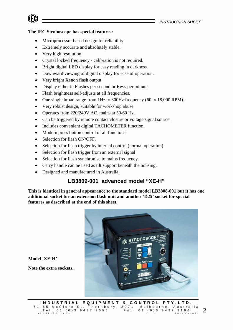
LB3809-001 advanced model “XE-H”
This is identical in general appearance to the standard model LB3808-001 but it has oneadditional socket for an extension flash unit and another ‘D25’ socket for specialfeatures as described at the end of this sheet.
Model ‘XE-H’
Note the extra sockets..
INSTRUCTION SHEET
I N D U S T R I A L E Q U I P M E N T & C O N T R O L P T Y . L T D .6 1 - 6 5 M c C l u r e S t . T h o r n b u r y . 3 0 7 1 M e l b o u r n e . A u s t r a l i a
T e l : 6 1 ( 0 ) 3 9 4 9 7 2 5 5 5 F a x : 6 1 ( 0 ) 3 9 4 9 7 2 1 6 6l b 3 8 0 8 - 0 0 1 . d o c 1 6 - J a n - 0 6
3
OPERATION OF INSTRUMENT:Power Up:
When 220/240V.AC. 50/60Hz. mains power is first applied, the LED display will show ‘IEC’then a quick display test. The display will then show the setting that was last used on theStroboscope the last time it was used. On power up, the flashing will be OFF. The smallLED indicating ‘flash off’ will be ON. To initiate flashing, press the FLASH ON/OFFbutton momentarily. NOTE: Accuracy and stability of the instrument, long or short term isabsolute and future calibration is not required.
Adjust Flash Frequency:To raise the flash rate, press the UP ARROW button. Each press of the button incrementsthe flash rate only slightly by one least significant digit. When the button is held depressed,after a very short delay, the rate increments faster. If the DOWN button is pressed while stilldepressing the UP button, the frequency rises very quickly. The same is true for the DOWNARROW button.
To Stop Flashing:Momentarily press the button marked FLASH ON/OFF. The flashing will stop but thedisplay will remain active. Note the display window indicates and a small LED on the panelreminds the user that the flashing has been switched off. If desired, the new flash frequencycan be preset with the flashing off. When ready, press the button momentarily again and theflashing will be ON.
The XENON Flash:The Xenon flash tube is limited to a maximum average power dissipation of about 25 watts.Internally, the brightness of the flash is automatically altered with flash frequency to obtainmaximum flash brilliance at any frequencies. Flash duration is about 20-50 microseconds atlow frequencies (brightest flash) and about 10 microseconds at high frequencies.
MODES: The MODES can be selected ONLY when the flash is off.INTERNAL mode means that the flashing of the Stroboscope is controlled by the pressbuttons on the panel.
EXTERNAL mode means that the flashing is controlled by external pulse source connectedto the 4mm sockets provided.
MAINS LOCK mode means that the display will indicate and the flash will occur exactly atthe rate of the mains frequency.
UNITS: The UNITS can be selected ONLY when the flash is off.Hz means Hertz which is the unit of frequency of events occurring per second. In this case itmeans Flashes per second.
RPM means revolutions per minute of the device being observed. Used mainly inengineering and automotive fields.

INSTRUCTION SHEET
I N D U S T R I A L E Q U I P M E N T & C O N T R O L P T Y . L T D .6 1 - 6 5 M c C l u r e S t . T h o r n b u r y . 3 0 7 1 M e l b o u r n e . A u s t r a l i a
T e l : 6 1 ( 0 ) 3 9 4 9 7 2 5 5 5 F a x : 6 1 ( 0 ) 3 9 4 9 7 2 1 6 6l b 3 8 0 8 - 0 0 1 . d o c 1 6 - J a n - 0 6
4
SOCKETS for Trigger and Measurement of external frequencies.The two 4mm sockets accept signals for triggering the flash. The voltage present at thesesockets is about 750 millivolts.
Signal required: A short circuit of the two sockets will produce a single flash so that asimple external mechanical switch can trigger the strobe. A moving device can be arrangedto operate a simple switch and the Stroboscope flash will be synchronised exactly with themotion. The speed of the motion will be displayed in the selected unit and the image viewedwill be perfectly stationary.
Alternatively, an electrical signal or square wave trigger pulse driving from less than 500mVlow rising to 1.5V high (up to 20V.max) will also trigger the flash. Duration of signalshould be at least 1 millisecond.
TAKING MEASUREMENTS: techniquesTACHOMETER: If an external signal is used to trigger the Xenon flash, the digitaldisplay also indicates the flash rate being triggered. If the flash is turned OFF, the displaycontinues to display the flash rate either in RPM or Hz as selected. This means theinstrument can be used to produce a perfectly synchronised “Frozen Image” or can be usedas a Tachometer from an external signal source.
MULTIPLE IMAGES: In the case of symmetrically shaped objects such as a fan or ahexagonal nut and almost all wheels and gears, care must be taken to ensure that thestationary image seen is caused by one single flash per revolution.
Consider a four bladed fan rotating at 3000 RPM or 50 RPSecond. A stationary image willbe observed when the flash frequency is 50 per second, that is one flash per revolution.Since there are four symmetrically positioned blades, there will be another stationary imageat 100 flashes/second (each half turn) and also at 200 flashes/second (each quarter turn).
To overcome this problem, a temporary mark with adhesive tape or chalk should be placedon one blade to upset the optical symmetry so that multiple images can easily bedistinguished from the 1:1 direct reading image.
However, after marking the blade, it will be found that another stationary image will befound at 25FPS (two turns per flash) and 16-2/3FPS (three turns per flash) and 12-1/2FPS(four turns per flash) and so on.
THE ‘GOLDEN’ RULE:
Using a distinguishing mark on a rotating object, viewed from the front, the first singleimage observed whilst reducing the flash rate from maximum is the true direct readingimage.
INSTRUCTION SHEET
I N D U S T R I A L E Q U I P M E N T & C O N T R O L P T Y . L T D .6 1 - 6 5 M c C l u r e S t . T h o r n b u r y . 3 0 7 1 M e l b o u r n e . A u s t r a l i a
T e l : 6 1 ( 0 ) 3 9 4 9 7 2 5 5 5 F a x : 6 1 ( 0 ) 3 9 4 9 7 2 1 6 6l b 3 8 0 8 - 0 0 1 . d o c 1 6 - J a n - 0 6
5
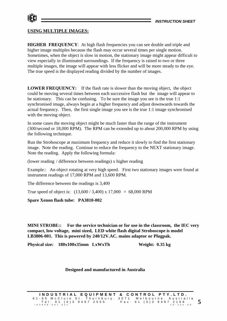
USING MULTIPLE IMAGES:
HIGHER FREQUENCY: At high flash frequencies you can see double and triple andhigher image multiples because the flash may occur several times per single motion.Sometimes, when the object is slow in motion, the stationary image might appear difficult toview especially in illuminated surroundings. If the frequency is raised to two or threemultiple images, the image will appear with less flicker and will be more steady to the eye.The true speed is the displayed reading divided by the number of images.
LOWER FREQUENCY: If the flash rate is slower than the moving object, the objectcould be moving several times between each successive flash but the image will appear tobe stationary. This can be confusing. To be sure the image you see is the true 1:1synchronised image, always begin at a higher frequency and adjust downwards towards theactual frequency. Then, the first single image you see is the true 1:1 image synchronisedwith the moving object.
In some cases the moving object might be much faster than the range of the instrument(300/second or 18,000 RPM). The RPM can be extended up to about 200,000 RPM by usingthe following technique.
Run the Stroboscope at maximum frequency and reduce it slowly to find the first stationaryimage. Note the reading. Continue to reduce the frequency to the NEXT stationary image.Note the reading. Apply the following formula:
(lower reading / difference between readings) x higher reading
Example:: An object rotating at very high speed. First two stationary images were found atinstrument readings of 17,000 RPM and 13,600 RPM.
The difference between the readings is 3,400
True speed of object is: (13,600 / 3,400) x 17,000 = 68,000 RPM
Spare Xenon flash tube: PA3810-002
MINI STROBE:: For the service technician or for use in the classroom, the IEC verycompact, low voltage, mini sized, LED white flash digital Stroboscope is modelLB3806-001. This is powered by 240/12V.AC. mains adaptor or Plugpak.
Physical size: 180x100x35mm LxWxTh Weight: 0.35 kg
Designed and manufactured in Australia
INSTRUCTION SHEET
I N D U S T R I A L E Q U I P M E N T & C O N T R O L P T Y . L T D .6 1 - 6 5 M c C l u r e S t . T h o r n b u r y . 3 0 7 1 M e l b o u r n e . A u s t r a l i a
T e l : 6 1 ( 0 ) 3 9 4 9 7 2 5 5 5 F a x : 6 1 ( 0 ) 3 9 4 9 7 2 1 6 6l b 3 8 0 8 - 0 0 1 . d o c 1 6 - J a n - 0 6
6
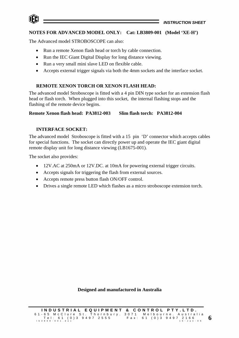
NOTES FOR ADVANCED MODEL ONLY: Cat: LB3809-001 (Model ‘XE-H’)
The Advanced model STROBOSCOPE can also:
• Run a remote Xenon flash head or torch by cable connection.• Run the IEC Giant Digital Display for long distance viewing.• Run a very small mini slave LED on flexible cable.• Accepts external trigger signals via both the 4mm sockets and the interface socket.
REMOTE XENON TORCH OR XENON FLASH HEAD:The advanced model Stroboscope is fitted with a 4 pin DIN type socket for an extension flashhead or flash torch. When plugged into this socket, the internal flashing stops and theflashing of the remote device begins.
Remote Xenon flash head: PA3812-003 Slim flash torch: PA3812-004
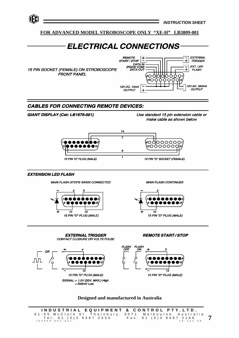
INTERFACE SOCKET:The advanced model Stroboscope is fitted with a 15 pin ‘D’ connector which accepts cablesfor special functions. The socket can directly power up and operate the IEC giant digitalremote display unit for long distance viewing (LB1675-001).
The socket also provides:
• 12V.AC at 250mA or 12V.DC. at 10mA for powering external trigger circuits.• Accepts signals for triggering the flash from external sources.• Accepts remote press button flash ON/OFF control.• Drives a single remote LED which flashes as a micro stroboscope extension torch.
Designed and manufactured in Australia
INSTRUCTION SHEET
I N D U S T R I A L E Q U I P M E N T & C O N T R O L P T Y . L T D .6 1 - 6 5 M c C l u r e S t . T h o r n b u r y . 3 0 7 1 M e l b o u r n e . A u s t r a l i a
T e l : 6 1 ( 0 ) 3 9 4 9 7 2 5 5 5 F a x : 6 1 ( 0 ) 3 9 4 9 7 2 1 6 6l b 3 8 0 8 - 0 0 1 . d o c 1 6 - J a n - 0 6
7
FOR ADVANCED MODEL STROBOSCOPE ONLY “XE-H” LB3809-001
Designed and manufactured in Australia