Embed Size (px)
Citation preview
STRUCTUARAL ENGINEERS ASSOCIATIONOF NORTHERN CALIFORNIA
GUIDELINESFOR
WELDING PROCEDURE SPECIFICATIONS
Prepared by theSEAONC Construction Quality Assurance Committee
ARAL
STRUCTURAL ENGINEERS ASSOCIATIONOF NORTHERN CALIFORNIA
Board of Directors, 2006
Andrew Merovich, PresidentDouglas Hohbach, Vice President
Jamison Curry, SecretaryMichael Fretz, Treasurer
Simin Nasseh, Past PresidentWilliam Andrews, DirectorGary Mochizuki, Director
David McCormick, DirectorDavid Murphy, Director
Disclaimer
While the information presented in the document is believed to be correct, SEAONC and its Board andCommittees assume no liability for its accuracy or for the opinions expressed herein. The material presented in this
document should not be used or relied upon for any specific application without competent examination andverification of its accuracy, suitability, and applicability by qualified professionals. Users of information from this
document assume all liability arising from such use.
Structural Engineers Association of Northern California© 2006 SEAONC
All rights reserved. This document or any part thereof may not be reproduced in any form without thewritten permission of the Structural Engineers Association of Northern California.
STRUCTURAL ENGINEERS ASSOCIATION OF NORTHERN CALIFORNIA
Guidelines for Welding Procedure Specifications
STRUCTURAL ENGINEERS ASSOCIATION OF NORTHERN CALIFORNIA 575 Market Street, Suite 2125San Francisco, CA 94105-2870
Phone: (415) 974-5147 Fax: (415) 764-4915Email: [email protected]://www..seaonc.org
These guidelines were written by members ofthe SEAONC Construction Quality Assurance Committee.
Construction Quality Assurance CommitteeMember NameMember NameMember NameMember NameMember NameMember NameMember NameMember NameMember NameMember Name
The committee acknowledges the following SEAONC membersfor their comments, suggestions, and assistance.
Peter BankA.L. Collin
Ronald O. HamburgerBret Lizundia
Ronald F. MiddlebrookPeter Revelli
Joseph R. SuttonAndrew Whittaker
STRUCTURAL ENGINEERS ASSOCIATION OF NORTHERN CALIFORNIA
IntroductionAlthough the engineer of record (EOR) is not ex-
pected to be an expert in welding, the responsibility ofthe EOR extends beyond the completion of the plansand specifications to the as-erected condition of a struc-ture. This is particularly the case for seismically loadedstructures, where the performance may depend on theproperties and geometry of the erected structure. The2002 AISC Seismic Provisions for Structural Steel Build-ings (Section 7.3), for example, requires the EOR to ap-prove each welding procedure specification (WPS) usedin fabrication and erection. The need for this require-ment was demonstrated by the 1994 Northridge earth-quake, in which steel moment frames and other weldedconnections fractured with minimal ductility, instead ofabsorbing plastic strains as expected. The causes ofthese fractures included in adequate oversight, insuffi-cient toughness in the connection weldment, and WPSsthat either did not exist or did not conform to the weld-ing code, AWS D1.1. As a result, the EOR is now ex-pected to take an active role in the review of weldingdocuments.AWS D1.1 describes welding as an engi-neered process. Requirements are specified for weldingelectrode and usage parameters, equipment, steels to bejoined, joint configurations, welder (performance) quali-fications and workmanship for the purpose of produc-ing a sound weld joining the steel materials.
AWS provisions for confirming the workmanshipability of the individual welder, called welder qualifica-tion (also known as “certification”), are well known andwidely enforced. The importance of the welder in theprocess is critical and is usually addressed by steel fabri-cators, erectors, and inspectors during the productionprocess.The materials and parameters of the welding
process are often taken for granted and not properlydocumented in the required written form known as theWelding Procedure Specifications (hereafter referred toas WPSs). Use of a prequalified joint without any fur-ther documentation is often mistakenly thought to be allthat is required. Welders and inspectors often workwithout a written WPS and rely on their experience toproduce apparently good welds. As a result, welding istypically performed and inspected without the writtenWPS “recipe” that AWS D1.1 requires to help ensurethe consistent production of sound welds. All referencesin these guidelines to AWS D1.1 are to the 2004 edition.
PurposeThis document has been produced to inform and ed-
ucate structural engineers about WPSs and their role inthe quality assurance of welded connections. Weldingconsists of complicated and specialized processes. Thestructural engineer must have an understanding of theorganizational relationships and processes by which aspecified weld on a drawing is converted to a finishedconnection. The structural engineer should be aware ofthe definition, use, purpose of, and difference between,WPS, procedure qualification, welding procedure, andwelder qualification.
Understanding these provisions, the engineer shouldspecify submittal of WPSs analogous to other submittalssuch as concrete mix designs and shop drawings. Thecontractor is responsible for preparing the WPSs. AWSD1.1 states that WPSs that require qualification by test-ing be approved by the engineer, and further states that“The Engineer shall determine the suitability of all jointdetails to be used in a welded assembly.”
Guidelines for WeldingProcedure Specifications
SEAONC Construction Quality Assurance Committee
1
STRUCTURAL ENGINEERS ASSOCIATION OF NORTHERN CALIFORNIA
This document is intended to help engineers performthe review without additional specialized expertise in thedetailed requirements of welding. It is not recommend-ed that the engineer attempt such reviews if he or shedoes not feel technically qualified. A welding, metallur-gical, or testing agency consultant can be called in for amore technical review if necessary. Approval by the en-gineer should be based on his or her own expertise, orthe recommendations of a qualified consultant.
Definitions and Terminology
Essential variable: A welding process, base metal orjoint detail parameter that must be specified and limitedin the WPS. Information on essential variables are inAWS D1.1, Sections 3.6 and 4.7.1 and Table 4.5. Forprequalified procedures, changes outside the limits ofessential variables require additional qualification testing,new PQR(s) and a revised WPS.
Joint: A single element of a connection where two ormore ends, surfaces, or edges are attached by welding, oraccording to AWS D1.1:The junction of members orthe edges of members that are to be joined or have beenjoined.
Nonessential variable: A welding process, base metalor joint detail parameter that must be specified in theWPS but may be changed during use. A change outsidethe limits of a nonessential variable does not require arevision to the WPS.
Prequalified WPS: A WPS that is exempt from qualifi-cation testing according to AWS D1.1.
Procedure Qualification: The demonstration by speci-fied tests that welds made by a specific procedure canmeet prescribed standards.
Procedure Qualification Test Record (PQR): Writ-ten documentation of the welding details and test resultsdemonstrating that welds using a particular WPS meetprescribed standards. A PQR is not required forprequalified WPSs.
Weldment: An assembly whose components are joinedby welding.
Welder Qualification: The demonstration, by specifiedtests, of a welder’s ability to produce welds meeting pre-scribed standards.
Welding Procedure: Detailed methods and practicesrequired to produce an acceptable weldment, includingweld processes, connections, joint welding procedures,joint details, preheat, inspection requirements, sequence,shrinkage allowance, postheat, and any other factors.
Welding Procedure Specification (WPS): A docu-ment detailing the method and the welding variables re-quired to produce a welded joint. It directs the welderhow to weld a specific joint, and includes requirementssuch as joint preparation, weld process, electrode typeand diameter, voltage and current, and travel speed. Itspurpose is to assure consistent production of soundwelds. The WPS is the focus of these guidelines.
Qualification RequirementsAWS D1.1, section 4 defines the qualification require-
ments for both WPSs and individual welders.
WPSDocumenting welding processes and variables in a
written WPS provides a standard method for reproduc-ing welds. A qualified WPS establishes that a weld jointproposed for fabrication meets AWS D1.1 requirementsfor weld quality. WPSs are qualified by testing accordingto procedures outlined in the code. However, someWPSs that use established procedures are “prequalified”and exempt from testing.
Prequalified WPSIn AWS D1.1, a WPS is considered to be prequalified
if the selected joint configuration, welding process andvariables, and other parameters conform to the manda-tory code requirements. A WPS that meets the criteriaAWS D1.1, Section 3 is exempt from qualificationtesting.
2
STRUCTURAL ENGINEERS ASSOCIATION OF NORTHERN CALIFORNIA
Although prequalified procedures are exempt fromtests, AWS D1.1 does require that the contractor preparewritten WPSs for the joints to be used in fabrication.These specifications indicate the limits and requirementsfor material and welding variables, providing documen-tation that the joint welding meets the requirements forprequalified status. A sample prequalified WPS is in-cluded as Exhibit 1.
WPS Qualified by TestingA WPS that is not prequalified must be qualified by
testing according to the requirements of AWS D1.1,Section 4.1.1. Qualification tests can demonstrate that awelded joint using a specific WPS meets the prescribedstandards of the code. The contractor or fabricator isrequired to make a test sample, typically a butt-jointedplate using the joint in the proposed WPS, for mechani-cal testing and evaluation. In preparing the test plate,the welder must follow the written details in the pro-posed WPS. A sample WPS qualified by testing is in-cluded as Exhibit 2.
The test plate configurations and dimensions areshown in AWS D1.1, Tables 4.2-4.4. Tests may includevisual inspection, tensile strength, guided bends, macro-etches, radiography, and impact tests. If the test resultsdo not meet the requirements of AWS D1.1 or projectspecifications, then a new WPS must be prepared andqualified by testing.
Procedure Qualification RecordA procedure qualification record (PQR) is written to
document the actual welding variables used and the testresults for a proposed WPS. Each WPS qualified bytesting is supported by one or more PQRs. A samplePQR supporting the WPS in Exhibit 2 is included as Ex-hibit 2A.
Revision and RequalificationIf any welding variables are changed in a WPS, then a
new WPS may have to be written to reflect the changes.Depending on which variables are changed, the revisedWPS may have to be requalified by testing. AWS D1.1specifies the type of changes requiring requalification.
Welder QualificationIndividual welders must be qualified to perform spe-
cific welds. The contractor or fabricator qualifies eachwelder for each WPS and position. The Commentary inAWS D1.1, section C4.18 states, “The welder qualifica-tion test is specifically designed to determine a welder’sability to produce sound welds in any given test joint.After successfully completing the welder qualificationtests, the welder should be considered to have minimumacceptable qualifications.”
AWS D1.1 defines welder qualification requirements.Each welder’s qualification remains in effect indefinitelyunless (1) the welder is not engaged in a given processof welding for which the welder is qualified for a periodexceeding six months, or (2) there is some specific rea-son to question a welder’s ability. A sample welder quali-fication test record is included as Exhibit 3.
Engineers’ Project Specifications forWPS
The structural engineer needs to request WPSs foreach type of weld joint to be used on a project. Thestructural engineer’s request for WPS will typically ap-pear in the structural steel section of the project specifi-cations. To ensure that WPSs are used, references needto be included in several places in the section. Sampleproject requirements for WPS are included as Exhibit 4.
An important item to consider for inclusion in theproject specifications is a requirement that the manufac-turer and specific electrode be stated in the WPS. AWSuses the concept of “essential variable”, which for ourpurposes can be considered a parameter that cannot bechanged without resubmittal by the contractor. Manu-facturer and specific electrode are not essential variablesin AWS D1.1. The code thus allows electrode substitu-tion by the contractor during fabrication. The structuralengineer can require the electrode be defined in the sub-mittal, and certainly should in the case of critical struc-tural welds. This will prohibit substitution of an elec-trode with parameters that might not comply with theWPS. Many in the welding industry recommend theelectrode be defined in all submittals.
3
STRUCTURAL ENGINEERS ASSOCIATION OF NORTHERN CALIFORNIA
Project specifications may also describe methods orpreparation, welding parameters, inspection require-ments, and mitigation methods for rejected welds. Ad-ditional requirements, such as steel chemical analysis andsequence of welded construction may also be includedin the project specifications. These are often referred toas welding procedures but should not be confused withWPSs.
Review of WPSSubmittal of WPSs should be in a timely manner to
allow for adequate review. WPSs should be includedwith any shop drawings referencing welds. The structur-al engineer should review WPSs for completeness andconformance to project specifications. The structuralengineer need not be a welding specialist to be able toreview the completeness and accuracy of WPSs. As aminimum the structural engineer should verify that thejoint details, material thickness and grades, and weldingpositions in the design documents are covered by thesubmitted WPSs. If the structural engineer determinesadditional review is necessary, the documents can be for-warded to a testing agency or welding consultant. Theconsultant should provide comments to the structuralengineer for incorporation in the WPS submittal re-sponse.
The testing agency verifies individual welder qualifica-tions during steel fabrication and erection. Welder quali-fications do not ordinarily need to be submitted to thestructural engineer for review. Structural engineersshould be alert to the possibility of receiving welderqualifications when WPS submittals are required.
Use During ProjectThe use of written WPSs during appropriate phases
of a project provides the welder with the basic weldingand weld joint requirements and the inspector and struc-tural engineer with the criteria to evaluate the quality ofwelding. AWS D1.1, Sections 3.6 and 4.2.3 requiresWPSs to be available to those “authorized to use or ex-amine them”. Written WPSs should be available at thework site for both welders and inspectors. The WPSsprovide the welder and inspector the information neces-
4
sary to set and monitor the variables essential to eachwelding process and weld joint configuration. The in-spector can then assure that proper welding parametersare being followed or note deviations. The structuralengineer should promptly address any nonconformanceto an approved WPS.
STRUCTURAL ENGINEERS ASSOCIATION OF NORTHERN CALIFORNIA
5
Exhibits
Exhibit 1 PREQUALIFIED Welding Procedure Specification
Exhibit 2 QUALIFIED BY TESTING Welding Procedure Specification
Exhibit 2A Procedure Qualification Record
Exhibit 3 Welder Performance Qualification Test Record
Exhibit 4 Project Specification
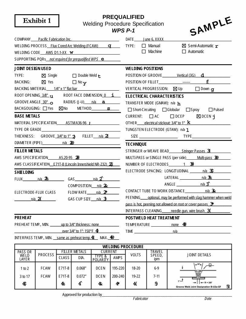
PREQUALIFIEDWelding Procedure Specification
WPS P-1
COMPANY____Pacific Fabrication Inc.__________________________
WELDING PROCESS__Flux Cored Arc Welding (FCAW)____________
WELDING CODE___AWS D1.1-XX_____________________________
SUPPORTING PQRs__not required for prequalified WPS____________
DATE_____June 6, XXXX_____________________________________
TYPE: Manual Semi-AutomaticMachine Automatic
JOINT DESIGN USED
TYPE: Single Double Weld
BACKING: Yes No
BACKING MATERIAL____1/4” x 1” flat bar_______________________
ROOT OPENING_3/8”_ ROOT FACE DIMENSION_0________
GROOVE ANGLE_30°_ RADIUS (J-U)____n/a_____________
BACKGOUGING: Yes No METHOD_______________
WELDING POSITIONS
POSITION OF GROOVE________Vertical (3G)___________________
POSITION OF FILLET_____________-------______________________
VERTICAL PROGRESSION: Up Down
BASE METALS
MATERIAL SPECIFICATION_____ASTM A36-96__________________
TYPE OR GRADE___________________________________________
THICKNESS: GROOVE_3/4” to 1”_ FILLET___n/a_________
DIAMETER (PIPE)___________n/a_____________________________
FILLER METALS
AWS SPECIFICATION______A5.20-95__________________________
AWS CLASSIFICATION__E71T-8 (Lincoln Innershield NR-232)_______
SHIELDING
FLUX________n/a____________ GAS__________n/a____________
COMPOSITION___n/a__________
ELECTRODE-FLUX CLASS FLOW RATE_____n/a__________
_________n/a___________ GAS CUP SIZE___n/a__________
ELECTRICAL CHARACTERISTICS
TRANSFER MODE (GMAW): n/a
Short-Circuiting Globular Spray Pulsed
CURRENT: AC DCEP DCEN
OTHER____electrical stickout: 3/4” to 1”_________________________
TUNGSTEN ELECTRODE (GTAW): n/a
SIZE _____________________ TYPE_____________________
TECHNIQUE
STRINGER or WEAVE BEAD_______Stringer Passes______________
MULTI-PASS or SINGLE PASS (per side)______Multi-pass__________
NUMBER OF ELECTRODES________1_________________________
ELECTRODE SPACING: LONGITUDINAL _______n/a_____________
LATERAL ____________n/a_____________
ANGLE _____________n/a______________
CONTACT TUBE TO WORK DISTANCE___________n/a____________
PEENING____optional, may be performed with slag hammer when weld
pass is hot, peening not allowed on root or cover passes_____________
INTERPASS CLEANING_____needle gun, wire brush______________
PREHEAT
PREHEAT TEMP., MIN. ______up to 3/4” thickness: none___________
__________________________over 3/4” to 1”: 150°F______________
INTERPASS TEMP., MIN. __same as preheat temp.____ MAX.______
POSTWELD HEAT TREATMENT
TEMPERATURE ___________none_____________________________
TIME _____________________n/a_____________________________
SAMPLE
WELDING PROCEDUREPASS OR
WELDLAYER
PROCESSFILLER METALS CURRENT
VOLTSTRAVELSPEED,
ipmJOINT DETAILS
CLASS DIA. TYPE &POLARITY AMPS
1 to 2
3 to 17
FCAW
FCAW
E71T-8
E71T-8
0.068”
0.072”
DCEN
DCEN
195-220
200-240
18-20
19-22
6-9
7-11
Approved for production by_______________________________________________________________________Fabricator Date
Exhibit 1
qw
e
r
ty
u i
o as
df
g
h
jk
l
;
2) 2!2@
2#2$
2% 2̂2&2*3)2(
3!3@
3#3$3%3̂3&
3*3(
4)4! 4@
4#
4$ 4% 4̂ 4& 4* 4( 5) 5!
Exhibit 1
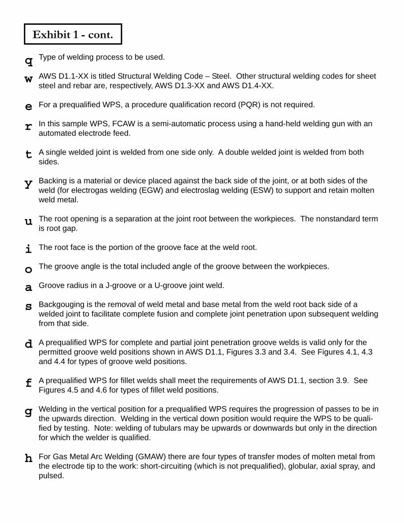
Exhibit 1 - cont.
Type of welding process to be used.
AWS D1.1-XX is titled Structural Welding Code – Steel. Other structural welding codes for sheetsteel and rebar are, respectively, AWS D1.3-XX and AWS D1.4-XX.
For a prequalified WPS, a procedure qualification record (PQR) is not required.
In this sample WPS, FCAW is a semi-automatic process using a hand-held welding gun with anautomated electrode feed.
A single welded joint is welded from one side only. A double welded joint is welded from bothsides.
Backing is a material or device placed against the back side of the joint, or at both sides of theweld (for electrogas welding (EGW) and electroslag welding (ESW) to support and retain moltenweld metal.
The root opening is a separation at the joint root between the workpieces. The nonstandard termis root gap.
The root face is the portion of the groove face at the weld root.
The groove angle is the total included angle of the groove between the workpieces.
Groove radius in a J-groove or a U-groove joint weld.
Backgouging is the removal of weld metal and base metal from the weld root back side of awelded joint to facilitate complete fusion and complete joint penetration upon subsequent weldingfrom that side.
A prequalified WPS for complete and partial joint penetration groove welds is valid only for thepermitted groove weld positions shown in AWS D1.1, Figures 3.3 and 3.4. See Figures 4.1, 4.3and 4.4 for types of groove weld positions.
A prequalified WPS for fillet welds shall meet the requirements of AWS D1.1, section 3.9. SeeFigures 4.5 and 4.6 for types of fillet weld positions.
Welding in the vertical position for a prequalified WPS requires the progression of passes to be inthe upwards direction. Welding in the vertical down position would require the WPS to be quali-fied by testing. Note: welding of tubulars may be upwards or downwards but only in the directionfor which the welder is qualified.
For Gas Metal Arc Welding (GMAW) there are four types of transfer modes of molten metal fromthe electrode tip to the work: short-circuiting (which is not prequalified), globular, axial spray, andpulsed.
q
w
e
r
t
y
u
i
o
a
s
d
f
g
h
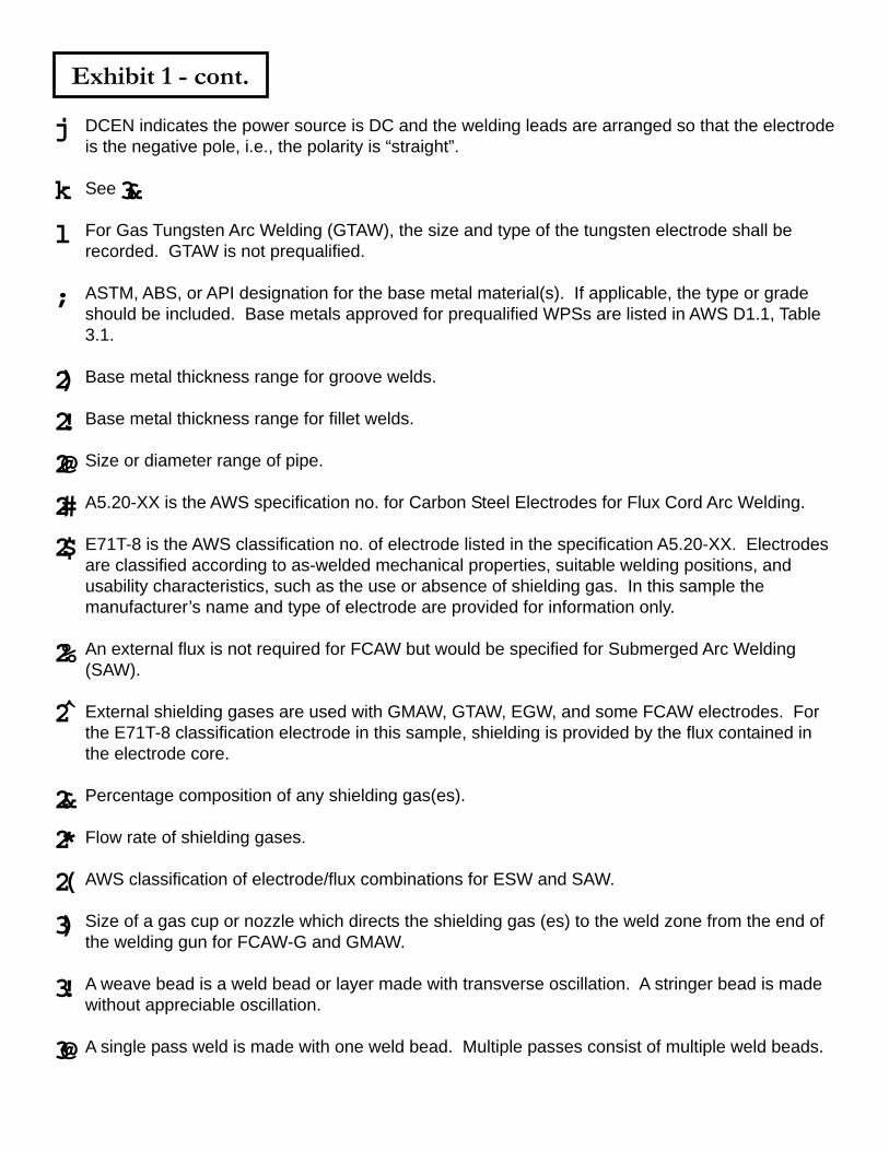
Exhibit 1 - cont.
DCEN indicates the power source is DC and the welding leads are arranged so that the electrodeis the negative pole, i.e., the polarity is “straight”.
See
For Gas Tungsten Arc Welding (GTAW), the size and type of the tungsten electrode shall berecorded. GTAW is not prequalified.
ASTM, ABS, or API designation for the base metal material(s). If applicable, the type or gradeshould be included. Base metals approved for prequalified WPSs are listed in AWS D1.1, Table3.1.
Base metal thickness range for groove welds.
Base metal thickness range for fillet welds.
Size or diameter range of pipe.
A5.20-XX is the AWS specification no. for Carbon Steel Electrodes for Flux Cord Arc Welding.
E71T-8 is the AWS classification no. of electrode listed in the specification A5.20-XX. Electrodesare classified according to as-welded mechanical properties, suitable welding positions, andusability characteristics, such as the use or absence of shielding gas. In this sample themanufacturer’s name and type of electrode are provided for information only.
An external flux is not required for FCAW but would be specified for Submerged Arc Welding(SAW).
External shielding gases are used with GMAW, GTAW, EGW, and some FCAW electrodes. Forthe E71T-8 classification electrode in this sample, shielding is provided by the flux contained inthe electrode core.
Percentage composition of any shielding gas(es).
Flow rate of shielding gases.
AWS classification of electrode/flux combinations for ESW and SAW.
Size of a gas cup or nozzle which directs the shielding gas (es) to the weld zone from the end ofthe welding gun for FCAW-G and GMAW.
A weave bead is a weld bead or layer made with transverse oscillation. A stringer bead is madewithout appreciable oscillation.
A single pass weld is made with one weld bead. Multiple passes consist of multiple weld beads.
j
k 3&
l
;
2)
2!
2@
2#
2$
2%
2̂
2&
2*
2(
3)
3!
3@
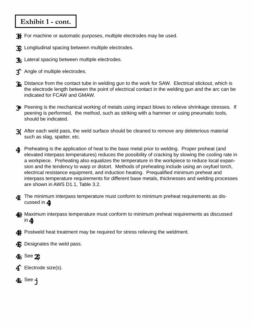
Exhibit 1 - cont.
For machine or automatic purposes, multiple electrodes may be used.
Longitudinal spacing between multiple electrodes.
Lateral spacing between multiple electrodes.
Angle of multiple electrodes.
Distance from the contact tube in welding gun to the work for SAW. Electrical stickout, which isthe electrode length between the point of electrical contact in the welding gun and the arc can beindicated for FCAW and GMAW.
Peening is the mechanical working of metals using impact blows to relieve shrinkage stresses. Ifpeening is performed, the method, such as striking with a hammer or using pneumatic tools,should be indicated.
After each weld pass, the weld surface should be cleaned to remove any deleterious materialsuch as slag, spatter, etc.
Preheating is the application of heat to the base metal prior to welding. Proper preheat (andelevated interpass temperatures) reduces the possibility of cracking by slowing the cooling rate ina workpiece. Preheating also equalizes the temperature in the workpiece to reduce local expan-sion and the tendency to warp or distort. Methods of preheating include using an oxyfuel torch,electrical resistance equipment, and induction heating. Prequalified minimum preheat andinterpass temperature requirements for different base metals, thicknesses and welding processesare shown in AWS D1.1, Table 3.2.
The minimum interpass temperature must conform to minimum preheat requirements as dis-cussed in
Maximum interpass temperature must conform to minimum preheat requirements as discussedin
Postweld heat treatment may be required for stress relieving the weldment.
Designates the weld pass.
See
Electrode size(s).
See
3#
3$
3%
3̂
3&
3*
3(
4)4!
4@
4#
4$
4%
4̂
4&
4)
4)
2$
j
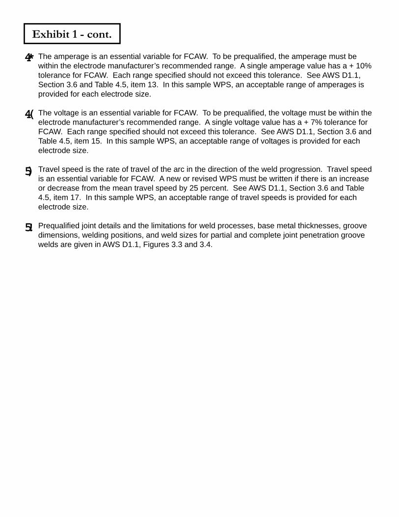
Exhibit 1 - cont.
The amperage is an essential variable for FCAW. To be prequalified, the amperage must bewithin the electrode manufacturer’s recommended range. A single amperage value has a + 10%tolerance for FCAW. Each range specified should not exceed this tolerance. See AWS D1.1,Section 3.6 and Table 4.5, item 13. In this sample WPS, an acceptable range of amperages isprovided for each electrode size.
The voltage is an essential variable for FCAW. To be prequalified, the voltage must be within theelectrode manufacturer’s recommended range. A single voltage value has a + 7% tolerance forFCAW. Each range specified should not exceed this tolerance. See AWS D1.1, Section 3.6 andTable 4.5, item 15. In this sample WPS, an acceptable range of voltages is provided for eachelectrode size.
Travel speed is the rate of travel of the arc in the direction of the weld progression. Travel speedis an essential variable for FCAW. A new or revised WPS must be written if there is an increaseor decrease from the mean travel speed by 25 percent. See AWS D1.1, Section 3.6 and Table4.5, item 17. In this sample WPS, an acceptable range of travel speeds is provided for eachelectrode size.
Prequalified joint details and the limitations for weld processes, base metal thicknesses, groovedimensions, welding positions, and weld sizes for partial and complete joint penetration groovewelds are given in AWS D1.1, Figures 3.3 and 3.4.
4*
4(
5)
5!
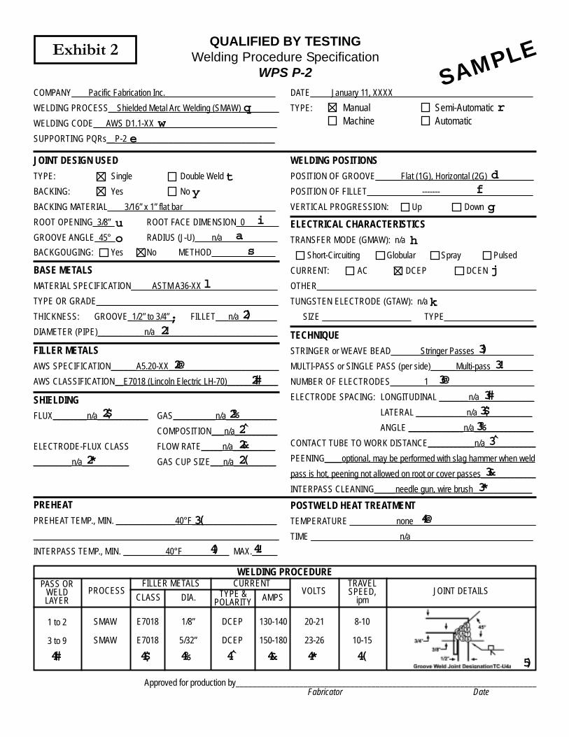
QUALIFIED BY TESTINGWelding Procedure Specification
WPS P-2
COMPANY____Pacific Fabrication Inc.__________________________
WELDING PROCESS__Shielded Metal Arc Welding (SMAW)_________
WELDING CODE___AWS D1.1-XX_____________________________
SUPPORTING PQRs__P-2___________________________________
DATE_____January 11, XXXX_________________________________
TYPE: Manual Semi-AutomaticMachine Automatic
JOINT DESIGN USED
TYPE: Single Double Weld
BACKING: Yes No
BACKING MATERIAL____3/16” x 1” flat bar______________________
ROOT OPENING_3/8”_ ROOT FACE DIMENSION_0________
GROOVE ANGLE_45°_ RADIUS (J-U)____n/a_____________
BACKGOUGING: Yes No METHOD_______________
WELDING POSITIONS
POSITION OF GROOVE______Flat (1G), Horizontal (2G)___________
POSITION OF FILLET_____________-------______________________
VERTICAL PROGRESSION: Up Down
BASE METALS
MATERIAL SPECIFICATION_____ASTM A36-XX__________________
TYPE OR GRADE___________________________________________
THICKNESS: GROOVE_1/2” to 3/4”_ FILLET___n/a_________
DIAMETER (PIPE)___________n/a_____________________________
FILLER METALS
AWS SPECIFICATION______A5.20-XX__________________________
AWS CLASSIFICATION__E7018 (Lincoln Electric LH-70)____________
SHIELDING
FLUX________n/a____________ GAS__________n/a____________
COMPOSITION___n/a__________
ELECTRODE-FLUX CLASS FLOW RATE_____n/a__________
_________n/a___________ GAS CUP SIZE___n/a__________
ELECTRICAL CHARACTERISTICS
TRANSFER MODE (GMAW): n/a
Short-Circuiting Globular Spray Pulsed
CURRENT: AC DCEP DCEN
OTHER____________________________________________________
TUNGSTEN ELECTRODE (GTAW): n/a
SIZE _____________________ TYPE_____________________
TECHNIQUE
STRINGER or WEAVE BEAD_______Stringer Passes______________
MULTI-PASS or SINGLE PASS (per side)______Multi-pass__________
NUMBER OF ELECTRODES________1_________________________
ELECTRODE SPACING: LONGITUDINAL _______n/a_____________
LATERAL ____________n/a_____________
ANGLE _____________n/a______________
CONTACT TUBE TO WORK DISTANCE___________n/a____________
PEENING____optional, may be performed with slag hammer when weld
pass is hot, peening not allowed on root or cover passes_____________
INTERPASS CLEANING_____needle gun, wire brush______________
PREHEAT
PREHEAT TEMP., MIN. ______________40°F____________________
__________________________________________________________
INTERPASS TEMP., MIN. __________40°F___________ MAX.______
POSTWELD HEAT TREATMENT
TEMPERATURE ___________none_____________________________
TIME _____________________n/a_____________________________
Exhibit 2
SAMPLE
WELDING PROCEDUREPASS OR
WELDLAYER
PROCESSFILLER METALS CURRENT
VOLTSTRAVELSPEED,
ipmJOINT DETAILS
CLASS DIA. TYPE &POLARITY AMPS
1 to 2
3 to 9
SMAW
SMAW
E7018
E7018
1/8”
5/32”
DCEP
DCEP
130-140
150-180
20-21
23-26
8-10
10-15
Approved for production by_______________________________________________________________________Fabricator Date
qw
e
r
ty
u i
o as
df
g
h
j
k
l
; 2)2!
2@2#
2$ 2%2̂2&2(2*
3)3!
3@3#3$3%3̂
3&3*
3(
4) 4!
4@
4# 4$ 4% 4̂ 4& 4* 4( 5)
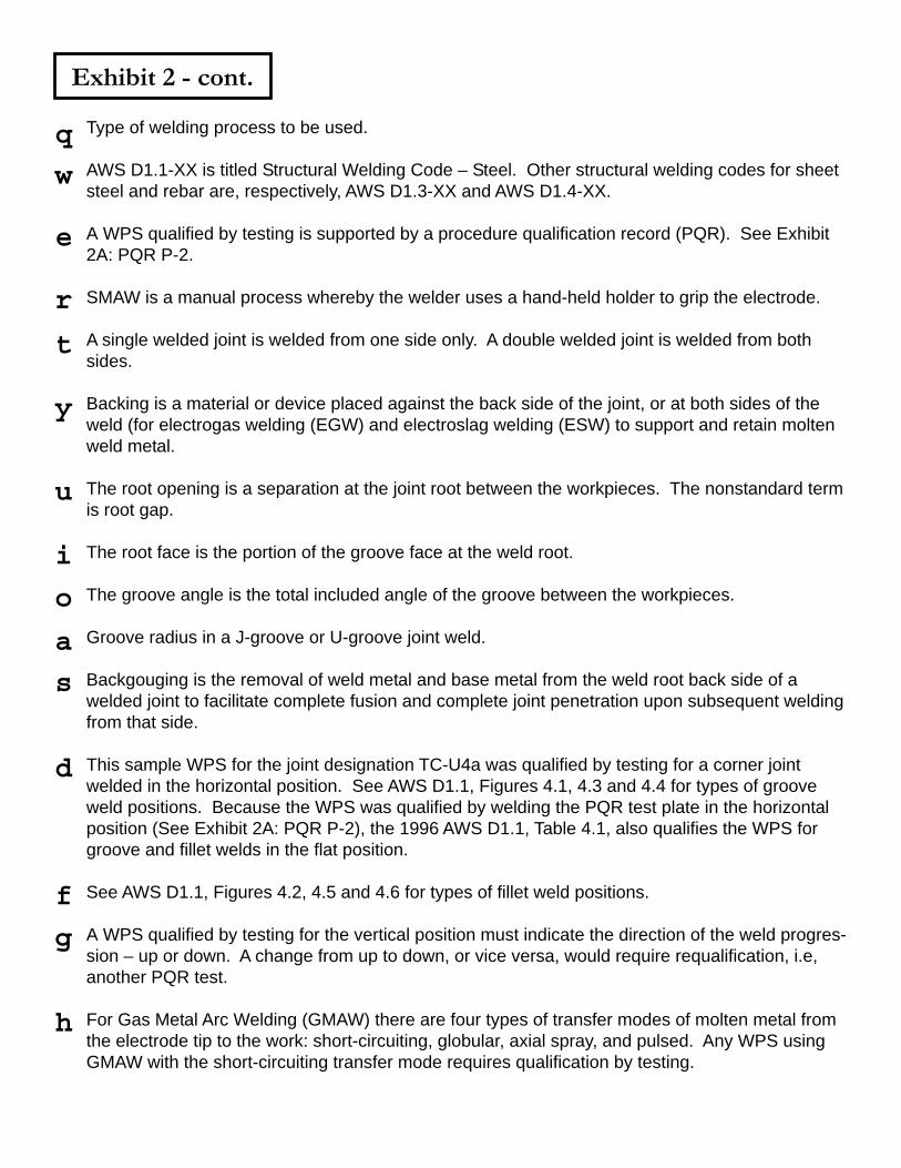
Exhibit 2 - cont.
Type of welding process to be used.
AWS D1.1-XX is titled Structural Welding Code – Steel. Other structural welding codes for sheetsteel and rebar are, respectively, AWS D1.3-XX and AWS D1.4-XX.
A WPS qualified by testing is supported by a procedure qualification record (PQR). See Exhibit2A: PQR P-2.
SMAW is a manual process whereby the welder uses a hand-held holder to grip the electrode.
A single welded joint is welded from one side only. A double welded joint is welded from bothsides.
Backing is a material or device placed against the back side of the joint, or at both sides of theweld (for electrogas welding (EGW) and electroslag welding (ESW) to support and retain moltenweld metal.
The root opening is a separation at the joint root between the workpieces. The nonstandard termis root gap.
The root face is the portion of the groove face at the weld root.
The groove angle is the total included angle of the groove between the workpieces.
Groove radius in a J-groove or U-groove joint weld.
Backgouging is the removal of weld metal and base metal from the weld root back side of awelded joint to facilitate complete fusion and complete joint penetration upon subsequent weldingfrom that side.
This sample WPS for the joint designation TC-U4a was qualified by testing for a corner jointwelded in the horizontal position. See AWS D1.1, Figures 4.1, 4.3 and 4.4 for types of grooveweld positions. Because the WPS was qualified by welding the PQR test plate in the horizontalposition (See Exhibit 2A: PQR P-2), the 1996 AWS D1.1, Table 4.1, also qualifies the WPS forgroove and fillet welds in the flat position.
See AWS D1.1, Figures 4.2, 4.5 and 4.6 for types of fillet weld positions.
A WPS qualified by testing for the vertical position must indicate the direction of the weld progres-sion – up or down. A change from up to down, or vice versa, would require requalification, i.e,another PQR test.
For Gas Metal Arc Welding (GMAW) there are four types of transfer modes of molten metal fromthe electrode tip to the work: short-circuiting, globular, axial spray, and pulsed. Any WPS usingGMAW with the short-circuiting transfer mode requires qualification by testing.
q
w
e
r
t
y
u
i
o
a
s
d
f
g
h
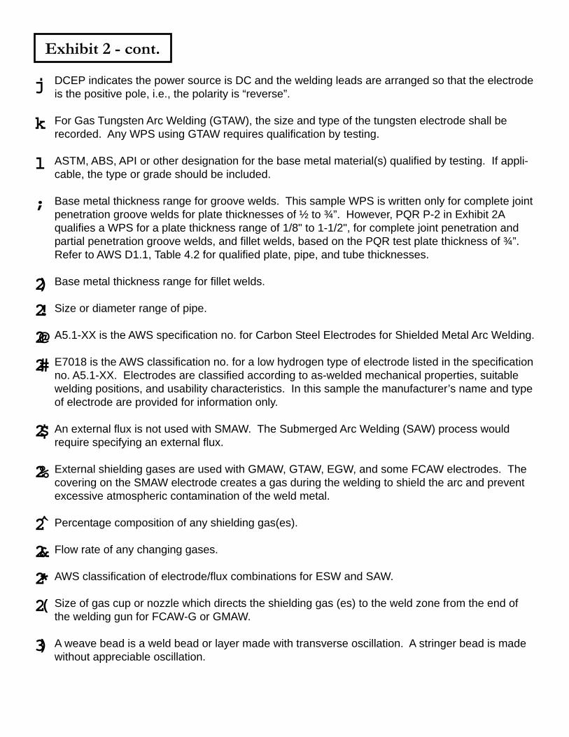
Exhibit 2 - cont.
DCEP indicates the power source is DC and the welding leads are arranged so that the electrodeis the positive pole, i.e., the polarity is “reverse”.
For Gas Tungsten Arc Welding (GTAW), the size and type of the tungsten electrode shall berecorded. Any WPS using GTAW requires qualification by testing.
ASTM, ABS, API or other designation for the base metal material(s) qualified by testing. If appli-cable, the type or grade should be included.
Base metal thickness range for groove welds. This sample WPS is written only for complete jointpenetration groove welds for plate thicknesses of ½ to ¾”. However, PQR P-2 in Exhibit 2Aqualifies a WPS for a plate thickness range of 1/8" to 1-1/2", for complete joint penetration andpartial penetration groove welds, and fillet welds, based on the PQR test plate thickness of ¾”.Refer to AWS D1.1, Table 4.2 for qualified plate, pipe, and tube thicknesses.
Base metal thickness range for fillet welds.
Size or diameter range of pipe.
A5.1-XX is the AWS specification no. for Carbon Steel Electrodes for Shielded Metal Arc Welding.
E7018 is the AWS classification no. for a low hydrogen type of electrode listed in the specificationno. A5.1-XX. Electrodes are classified according to as-welded mechanical properties, suitablewelding positions, and usability characteristics. In this sample the manufacturer’s name and typeof electrode are provided for information only.
An external flux is not used with SMAW. The Submerged Arc Welding (SAW) process wouldrequire specifying an external flux.
External shielding gases are used with GMAW, GTAW, EGW, and some FCAW electrodes. Thecovering on the SMAW electrode creates a gas during the welding to shield the arc and preventexcessive atmospheric contamination of the weld metal.
Percentage composition of any shielding gas(es).
Flow rate of any changing gases.
AWS classification of electrode/flux combinations for ESW and SAW.
Size of gas cup or nozzle which directs the shielding gas (es) to the weld zone from the end ofthe welding gun for FCAW-G or GMAW.
A weave bead is a weld bead or layer made with transverse oscillation. A stringer bead is madewithout appreciable oscillation.
j
k
l
;
2)
2!
2@
2#
2$
2%
2̂
2&
2*
2(
3)
A single pass weld is made with one weld bead. Multiple passes consist of multiple weld beads.
For machine or automatic processes, multiple electrodes may be used.
Longitudinal spacing between multiple electrodes.
Lateral spacing between multiple electrodes.
Angle of multiple electrodes.
Distance from the contact tube in welding gun to the work for SAW. Electrical stickout, which isthe electrode length between the point of electrical contact in the welding gun and the arc, can beindicated for FCAW and GMAW.
Mechanical working of metals using impact blows to relieve shrinkage stresses. If peening isperformed, the method, such as striking with a hammer or using pneumatic tools, should beindicated.
After each weld pass, the weld surface may be cleaned to remove any deleterious material suchas slag, spatter, etc.
The minimum preheat temperature for a FCAW, GMAW, SAW, or SMAW WPS qualified by testingis 25°F less than the preheat temperature used during the welding of the PQR test plate. SeeExhibit 2A: PQR P-2. Refer to AWS D1.1, Table 45, and Section 5.6 for allowable decreases inpreheat temperatures.
The minimum interpass temperature is equal to the minimum preheat temperature. Refer to AWSD1.1, Table 4.5, note 7, and Section 5.6.
Maximum interpass temperatures may be specified for welding of steels with toughness require-ments, high strength steels, quenched and tempered steels, etc.
Postweld heat treatment may be required for stress relieving the weldment.
Designates the weld pass.
See
Electrode size(s). See
A SMAW WPS qualified by testing must be re-qualified if the amperage, an essential variable, isoutside the range recommended by the electrode manufacturer. For other processes, re-qualifi-cation is required if the amperage varies from that used in the PQR test by more than the toler-ance given in AWS D1.1, Table 4.5.
Exhibit 2 - cont.
3!
3@
3#
3$
3%
3̂
3&
3*
3(
4)
4!
4@
4#
4$
4%
4̂
2#
j
Exhibit 2 - cont.
A SMAW WPS qualified by testing must be re-qualified if the voltage, an essential variable, isoutside the range recommended by the electrode manufacturer. For other processes, re-qualifi-cation is required if the voltage varies from that used in the PQR test by more than the tolerancegiven in AWS D1.1, Table 4.5.
A SMAW WPS qualified by testing must be re-qualified of the voltage, an essential variable, isoutside the range recommended by the electrode manufacturer. For other processes, re-qualifica-tion is required if the voltage varies from that used in the PQR test by more than the tolerancegiven in AWS D1.1, Table 4.5.
Travel speed is the speed of the arc in the direction of the weld progression. Travel speed is notan essential variable for SMAW. However, for other processes, requalification is required if thetravel speed varies from that used in the PQR test by more than the tolerance given in AWS D1.1,Table 4.5.
Joint details for the corner weld joint.
4&
4*
4(
5)
GUIDED BEND TESTS
Procedure Qualification RecordPQR P-2
COMPANY____Pacific Fabrication Inc.__________________________
WELDING PROCESS__Shielded Metal Arc Welding (SMAW)_________DATE_____January 11, XXXX_________________________________
WELDING CODE___AWS D1.1-XX_____________________________
Exhibit 2A SAMPLE
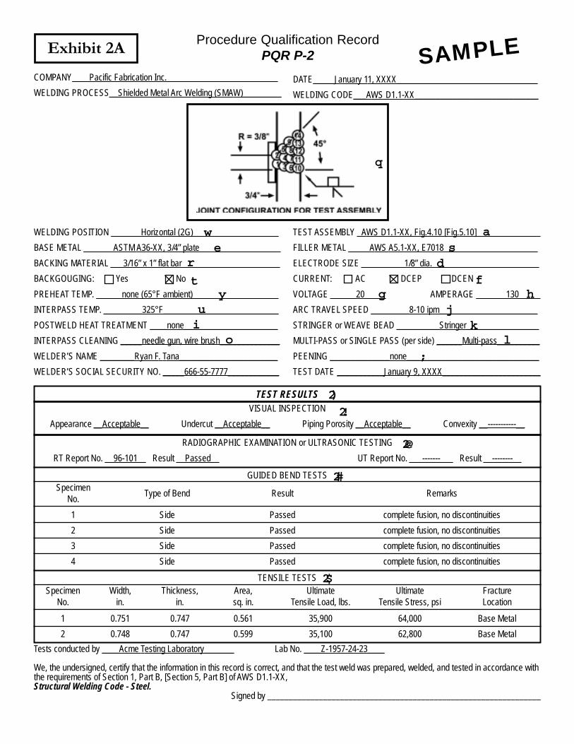
WELDING POSITION _______Horizontal (2G)____________________
BASE METAL _______ASTM A36-XX, 3/4” plate___________________
BACKING MATERIAL ___3/16” x 1” flat bar_______________________
BACKGOUGING: Yes No
PREHEAT TEMP. ______none (65°F ambient)____________________
INTERPASS TEMP. _________325°F___________________________
POSTWELD HEAT TREATMENT ____none______________________
INTERPASS CLEANING _____needle gun, wire brush______________
WELDER’S NAME ________Ryan F. Tana_______________________
WELDER’S SOCIAL SECURITY NO. _____666-55-7777____________
TEST ASSEMBLY _AWS D1.1-XX, Fig.4.10 [Fig.5.10]_______________
FILLER METAL _____AWS A5.1-XX, E7018______________________
ELECTRODE SIZE __________1/8” dia._________________________
CURRENT: AC DCEP DCEN
VOLTAGE ______20_____ AMPERAGE _______130_____
ARC TRAVEL SPEED _________8-10 ipm_______________________
STRINGER or WEAVE BEAD __________Stringer_________________
MULTI-PASS or SINGLE PASS (per side) ______Multi-pass__________
PEENING ______________none_______________________________
TEST DATE ___________January 9, XXXX_______________________
TEST RESULTSVISUAL INSPECTION
Appearance __Acceptable__ Undercut __Acceptable__ Piping Porosity __Acceptable__ Convexity __-----------__
RADIOGRAPHIC EXAMINATION or ULTRASONIC TESTING
RT Report No. __96-101__ Result __Passed__ UT Report No. ___-------___ Result __--------__
SpecimenNo.
ResultType of Bend Remarks
1
2
3
4
Side
Side
Side
Side
Passed
Passed
Passed
Passed
complete fusion, no discontinuities
complete fusion, no discontinuities
complete fusion, no discontinuities
complete fusion, no discontinuities
TENSILE TESTSSpecimen
No.Width,
in.Thickness,
in.Area,sq. in.
UltimateTensile Load, lbs.
UltimateTensile Stress, psi
FractureLocation
1
2
0.751
0.748
0.747
0.747
0.561
0.599
35,900
35,100
64,000
62,800
Base Metal
Base Metal
Tests conducted by ____Acme Testing Laboratory_______ Lab No. ____Z-1957-24-23____
We, the undersigned, certify that the information in this record is correct, and that the test weld was prepared, welded, and tested in accordance withthe requirements of Section 1, Part B, [Section 5, Part B] of AWS D1.1-XX,Structural Welding Code - Steel.
Signed by ________________________________________________________________
q
we
r
ty
ui
o
as
df
g hj
kl
;
2)2!
2@
2#
2$
Exhibit 2A - cont.
Joint details for the test assembly. Also shown are the sequence of weld passes. To qualify thecorner joint for WPS P-2 in Exhibit 2, a butt jointed PQR test plate, with the same joint configura-tion to be used in production, is welded. Specimens are removed from the completed test plateto evaluate the mechanical properties of the welded joint. See AWS D1.1, Figure 4.10 for di-mensions of the PQR test plate.
In this sample the complete joint penetration groove weld was welded in the horizontal (2G)position. Passing results for the PQR test plate qualifies the WPS for welding in the horizontaland flat positions for groove and fillet welds per the AWS D1.1, Table 4.1.
Base metal material(s) used for the PQR test plate.
Backing is a material or device placed against the back side of the joint, or at both sides of theweld in electroslag and electrogas welding, to support and retain molten weld metal.
Backgouging is the removal of weld metal and base metal from the weld root back side of awelded joint to facilitate complete fusion and complete joint penetration upon subsequent weld-ing from that side.
Preheat temperature used for welding of the PQR test plate. In this sample a preheat was notapplied to the test plate. Therefore, the temperature of the test plate, which was at the shopambient temperature, is recorded.
Interpass temperature during welding of the PQR test plate is recorded.
Postweld heat treatment used on the PQR test plate.
Method used to clean each weld pass.
See AWS D1.1, Figures 4.9, 4.10, and 4.11 for PQR test plate dimensions and locations of testspecimens.
AWS filler metal specification no. and classification no.
Size of electrode to weld PQR test plate.
DCEP indicates the power source is DC and the welding leads are arranged so that the elec-trode is the positive pole, i.e., the polarity is “reverse”.
Voltage used during welding of the PQR test plate.
Amperage used during welding of the PQR test plate.
Rate of travel for the arc stream in the direction of the weld progression.
q
w
e
r
t
y
u
i
o
a
s
d
f
g
h
j
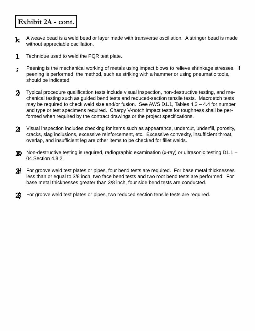
Exhibit 2A - cont.
A weave bead is a weld bead or layer made with transverse oscillation. A stringer bead is madewithout appreciable oscillation.
Technique used to weld the PQR test plate.
Peening is the mechanical working of metals using impact blows to relieve shrinkage stresses. Ifpeening is performed, the method, such as striking with a hammer or using pneumatic tools,should be indicated.
Typical procedure qualification tests include visual inspection, non-destructive testing, and me-chanical testing such as guided bend tests and reduced-section tensile tests. Macroetch testsmay be required to check weld size and/or fusion. See AWS D1.1, Tables 4.2 – 4.4 for numberand type or test specimens required. Charpy V-notch impact tests for toughness shall be per-formed when required by the contract drawings or the project specifications.
Visual inspection includes checking for items such as appearance, undercut, underfill, porosity,cracks, slag inclusions, excessive reinforcement, etc. Excessive convexity, insufficient throat,overlap, and insufficient leg are other items to be checked for fillet welds.
Non-destructive testing is required, radiographic examination (x-ray) or ultrasonic testing D1.1 –04 Section 4.8.2.
For groove weld test plates or pipes, four bend tests are required. For base metal thicknessesless than or equal to 3/8 inch, two face bend tests and two root bend tests are performed. Forbase metal thicknesses greater than 3/8 inch, four side bend tests are conducted.
For groove weld test plates or pipes, two reduced section tensile tests are required.
k
l
;
2)
2!
2@
2#
2$
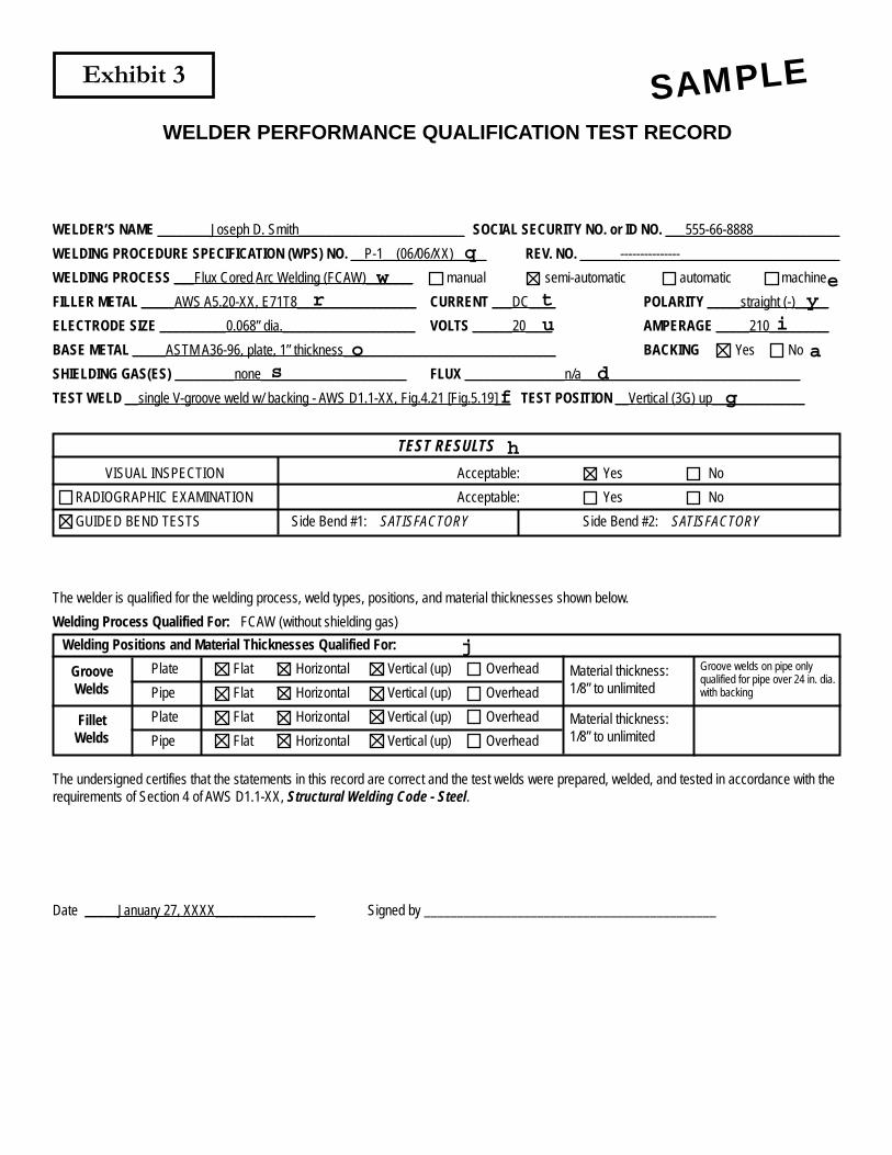
WELDER PERFORMANCE QUALIFICATION TEST RECORD
WELDER’S NAME ________Joseph D. Smith_________________________ SOCIAL SECURITY NO. or ID NO. ___555-66-8888_____________
WELDING PROCEDURE SPECIFICATION (WPS) NO. __P-1__(06/06/XX)_____ REV. NO. ______---------------________________________
WELDING PROCESS ___Flux Cored Arc Welding (FCAW)_______ manual semi-automatic automatic machine
FILLER METAL _____AWS A5.20-XX, E71T8__________________ CURRENT ___DC____ POLARITY _____straight (-)_____
ELECTRODE SIZE __________0.068” dia.____________________ VOLTS ______20____ AMPERAGE _____210_________
BASE METAL _____ASTM A36-96, plate, 1” thickness________________________________ BACKING Yes No
SHIELDING GAS(ES) _________none______________________ FLUX _______________n/a_________________________________
TEST WELD __single V-groove weld w/ backing - AWS D1.1-XX, Fig.4.21 [Fig.5.19]__ TEST POSITION __Vertical (3G) up______________
Exhibit 3 SAMPLE
TEST RESULTS
VISUAL INSPECTION
RADIOGRAPHIC EXAMINATION
GUIDED BEND TESTS
Acceptable: Yes No
Acceptable: Yes No
Side Bend #1: SATISFACTORY Side Bend #2: SATISFACTORY
The welder is qualified for the welding process, weld types, positions, and material thicknesses shown below.
Welding Process Qualified For: FCAW (without shielding gas)
Welding Positions and Material Thicknesses Qualified For:
Plate Flat Horizontal Vertical (up) Overhead
Pipe Flat Horizontal Vertical (up) Overhead
Plate Flat Horizontal Vertical (up) Overhead
Pipe Flat Horizontal Vertical (up) Overhead
GrooveWelds
FilletWelds
Material thickness:1/8” to unlimited
Material thickness:1/8” to unlimited
Groove welds on pipe onlyqualified for pipe over 24 in. dia.with backing
The undersigned certifies that the statements in this record are correct and the test welds were prepared, welded, and tested in accordance with therequirements of Section 4 of AWS D1.1-XX, Structural Welding Code - Steel.
Date _____January 27, XXXX_______________ Signed by ____________________________________________
qw e
r t yu i
o as d
f g
h
j
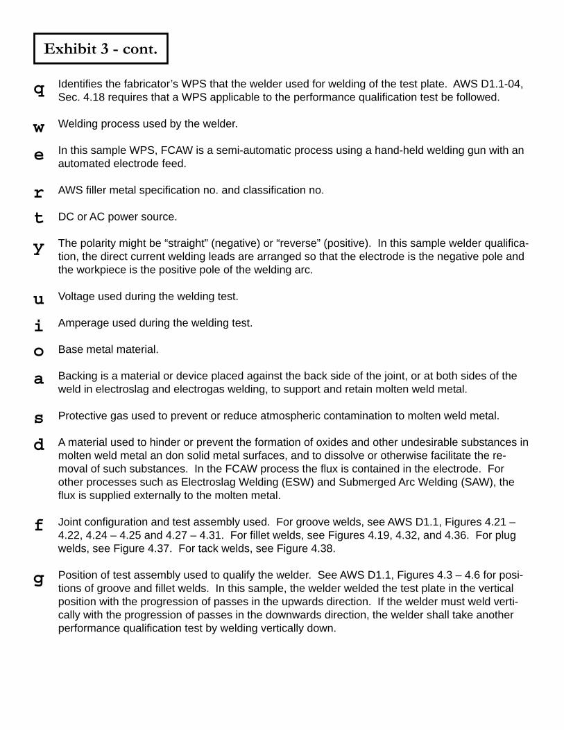
Exhibit 3 - cont.
Identifies the fabricator’s WPS that the welder used for welding of the test plate. AWS D1.1-04,Sec. 4.18 requires that a WPS applicable to the performance qualification test be followed.
Welding process used by the welder.
In this sample WPS, FCAW is a semi-automatic process using a hand-held welding gun with anautomated electrode feed.
AWS filler metal specification no. and classification no.
DC or AC power source.
The polarity might be “straight” (negative) or “reverse” (positive). In this sample welder qualifica-tion, the direct current welding leads are arranged so that the electrode is the negative pole andthe workpiece is the positive pole of the welding arc.
Voltage used during the welding test.
Amperage used during the welding test.
Base metal material.
Backing is a material or device placed against the back side of the joint, or at both sides of theweld in electroslag and electrogas welding, to support and retain molten weld metal.
Protective gas used to prevent or reduce atmospheric contamination to molten weld metal.
A material used to hinder or prevent the formation of oxides and other undesirable substances inmolten weld metal an don solid metal surfaces, and to dissolve or otherwise facilitate the re-moval of such substances. In the FCAW process the flux is contained in the electrode. Forother processes such as Electroslag Welding (ESW) and Submerged Arc Welding (SAW), theflux is supplied externally to the molten metal.
Joint configuration and test assembly used. For groove welds, see AWS D1.1, Figures 4.21 –4.22, 4.24 – 4.25 and 4.27 – 4.31. For fillet welds, see Figures 4.19, 4.32, and 4.36. For plugwelds, see Figure 4.37. For tack welds, see Figure 4.38.
Position of test assembly used to qualify the welder. See AWS D1.1, Figures 4.3 – 4.6 for posi-tions of groove and fillet welds. In this sample, the welder welded the test plate in the verticalposition with the progression of passes in the upwards direction. If the welder must weld verti-cally with the progression of passes in the downwards direction, the welder shall take anotherperformance qualification test by welding vertically down.
q
w
e
r
t
y
u
i
o
a
s
d
f
g
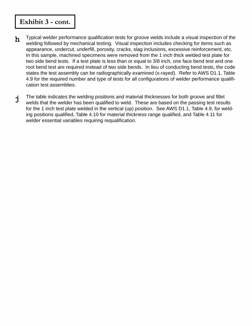
Exhibit 3 - cont.
Typical welder performance qualification tests for groove welds include a visual inspection of thewelding followed by mechanical testing. Visual inspection includes checking for items such asappearance, undercut, underfill, porosity, cracks, slag inclusions, excessive reinforcement, etc.In this sample, machined specimens were removed from the 1 inch thick welded test plate fortwo side bend tests. If a test plate is less than or equal to 3/8 inch, one face bend test and oneroot bend test are required instead of two side bends. In lieu of conducting bend tests, the codestates the test assembly can be radiographically examined (x-rayed). Refer to AWS D1.1, Table4.9 for the required number and type of tests for all configurations of welder performance qualifi-cation test assemblies.
The table indicates the welding positions and material thicknesses for both groove and filletwelds that the welder has been qualified to weld. These are based on the passing test resultsfor the 1 inch test plate welded in the vertical (up) position. See AWS D1.1, Table 4.9, for weld-ing positions qualified, Table 4.10 for material thickness range qualified, and Table 4.11 forwelder essential variables requiring requalification.
h
j
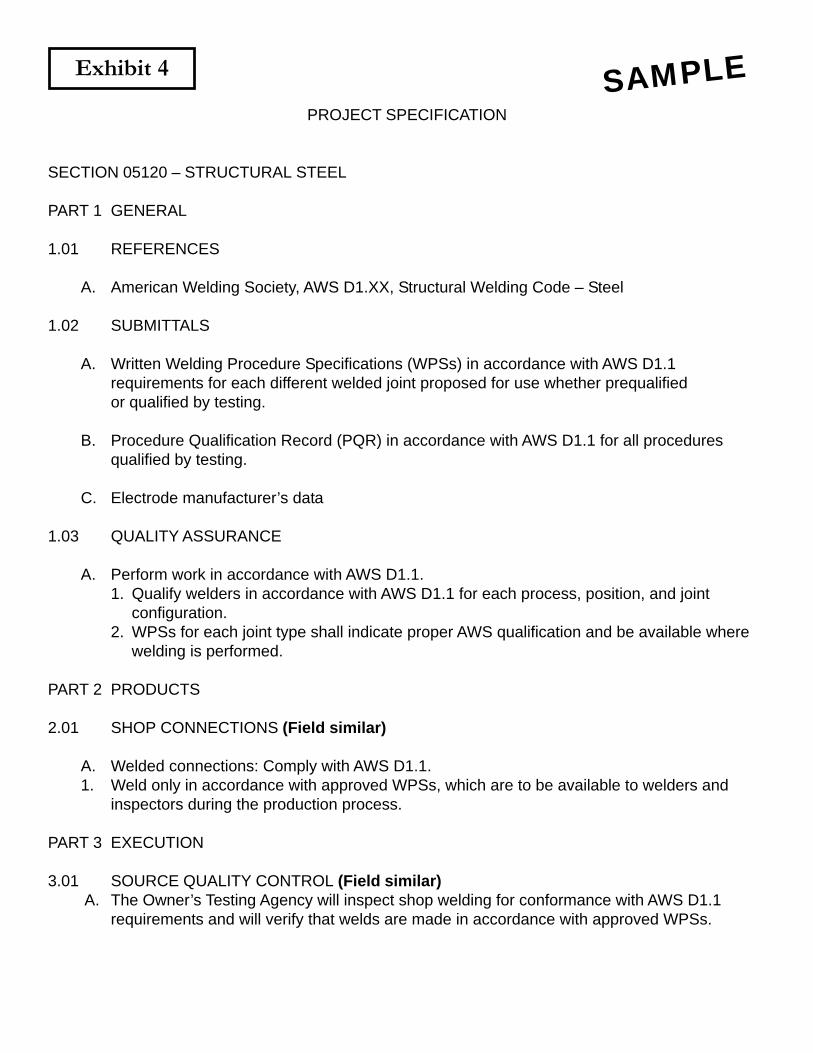
Exhibit 4
PROJECT SPECIFICATION
SECTION 05120 – STRUCTURAL STEEL
PART 1 GENERAL
1.01 REFERENCES
A. American Welding Society, AWS D1.XX, Structural Welding Code – Steel
1.02 SUBMITTALS
A. Written Welding Procedure Specifications (WPSs) in accordance with AWS D1.1requirements for each different welded joint proposed for use whether prequalifiedor qualified by testing.
B. Procedure Qualification Record (PQR) in accordance with AWS D1.1 for all proceduresqualified by testing.
C. Electrode manufacturer’s data
1.03 QUALITY ASSURANCE
A. Perform work in accordance with AWS D1.1.1. Qualify welders in accordance with AWS D1.1 for each process, position, and joint
configuration.2. WPSs for each joint type shall indicate proper AWS qualification and be available where
welding is performed.
PART 2 PRODUCTS
2.01 SHOP CONNECTIONS (Field similar)
A. Welded connections: Comply with AWS D1.1.1. Weld only in accordance with approved WPSs, which are to be available to welders and
inspectors during the production process.
PART 3 EXECUTION
3.01 SOURCE QUALITY CONTROL (Field similar) A. The Owner’s Testing Agency will inspect shop welding for conformance with AWS D1.1
requirements and will verify that welds are made in accordance with approved WPSs.
SAMPLE