Embed Size (px)
Citation preview
IJISET - International Journal of Innovative Science, Engineering & Technology, Vol. 2 Issue 1, January 2015.
www.ijiset.com
ISSN 2348 – 7968
502
Structural and Thermal Analysis on a Tapered Roller Bearing M. Prem Kumar1, Dr.C.J.Rao2
1 M.tech (Thermal Engg) Student, Aditya Institute of Technology and Management, Tekkali, Srikakulam Dist., Andhra Pradesh. 2Professor & Head, Dept. of Mechanical Engg, Aditya Institute of Technology and Management, Tekkali, Srikakulam Dist.,
Andhra Pradesh.
Abstract:
In the railroad industry, troubled bearings in service are primarily identified using wayside hot-box detectors (HBDs). Several bearings set-out for trending and classified as non-verified, due to no visible damage within a cone assembly. Subsequent laboratory experiments were performed to determine a minimum temperature and environment necessary to reproduce these discolorations which are mostly due to roller temperatures greater than 232oC (450oF) for periods of at least 4hours. Research is going on the possibility that rollers reaching such elevated temperatures without heating the bearing cup (outer race) to a temperature significant enough to trigger the HBDs. Considering the previous experimental and analytical work, a static-thermal finite element analysis (FEA) of a railroad bearing pressed onto an axle and was analyzed using ANSYS.
Analysis is carried out by considering certain radial load and thrust load. Present work shows the stresses at various temperatures, fatigue life, vibration characteristics and the dynamic response of a structure under the action of time-dependent loads. Also Present work evaluates the Hot Box Detector (HBD) temperature by showing the bearing safe temperature, failure temperature and stresses under cyclic loading. Key Words: Roller Bearing, Hot Box Detector, FEA and ANSYS etc..
INTRODUCTION Tapered-roller bearings are the most
widely used bearings in railroad cars. When operated under satisfactory load, alignment
and contaminant free conditions, the service life is exceptionally long.
As a general rule, bearings will outlast the wheel life, and survive several reconditioning cycles prior to being retired. At the end of their life, bearings will initiate fatigue, particularly subsurface fatigue, rather than wearing out due to surface abrasion. Fatigue failures, or sapling, can lead to material removal at the raceway surface which in turn will cause grease contamination and increased friction that manifests itself as heat within the bearing. Excessive heat will lower the viscosity of the lubricant, which reduces the thickness of the fluid film that separates the rolling surfaces. As a consequence, metal-to-metal contact occurs, which can hasten the onset of premature bearing failure. To identify distressed bearings in service, bearing health monitoring equipment is employed by the railroads to warn of impending failures as a method to ward off potentially catastrophic events, such as derailments. The most common method of monitoring bearing health is by conventional wayside Hot-Box Detectors which are strategically located to record bearing cup temperatures as the train passes. These devices are designed to identify those bearings which are operating at temperatures greater than 105.5oC (190oF) above ambient conditions. An extension of this practice is the tracking of temperature data and comparing individual bearings against the averages of the remainder along a train.
Identifying those bearings which are “trending” above normal allows the railroads to track bearings which appear to
IJISET - International Journal of Innovative Science, Engineering & Technology, Vol. 2 Issue 1, January 2015.
www.ijiset.com
ISSN 2348 – 7968
503
be distressed without waiting for a Hot-Box Detector (HBD) to be alarmed. As a diagnostic aid, bearings which are identified as hot are removed from service for later disassembly and inspection. In most cases, the cause of bearing overheating can be attributed to one of several known modes of bearing failure such as stalling, water contamination, loose bearings, broken components, damaged seals, etc. However, in some cases, the early set-out bearings do not exhibit any of the commonly documented causes of bearing failure and are, therefore, classified as non-verified. Upon closer disassembly and inspection, it has been observed that many of these non-verified bearings contain discolored rollers in an otherwise normal bearing. The discoloration of the steel is visual evidence that these rollers have been exposed to temperatures greater than the expected during normal operating conditions. Hence, initial work performed by the Tarawneh et al. [3], [23] focused on determining conditions that would replicate the discoloration observed in the rollers. A laboratory furnace was used to heat numerous rollers to elevated temperatures in various environments. Results indicated that the visual discoloration observed in bearings removed from service were rollers heated in grease to temperatures over 232oC (450oF) for a time period of at least 4 hours.
Some of the studies have utilized the Finite Element method to develop models to analyze specific phenomena of interest concerning different types of bearing assemblies and their components. In most cases, experimentally acquired data are used to validate the accuracy of the derived FE models. O Verstam [4] performed FE simulations using the MSC.MARC code to study the effect of bearing geometry on the residual stress-state in cold drawn wires, and verified the simulation results with data acquired from full-scale industrial
experiments. Wei et al. [5] used FE simulations to demonstrate that their proposed design of a deep end-cavity roller would enable a straight-profile-roller bearing to perform similar to a logarithmic profile roller bearing by eliminating the sharp edge-stresses at the two apexes of the rollers. Demirhan and Kanber [6] used ANSYS to investigate the stress and displacement distributions on cylindrical roller bearing rings. The study concluded that the stresses and displacements have different distribution characteristics on the inner and outer faces of the rings and are not uniformly distributed along the height of the rings because of large stresses at the contact points. Vernersson [7] developed a FE model for heat transfer from the rolling wheel into the rail where a film with thermal contact resistance is placed at the wheel-rail contact interface. The proposed FE model, which is validated by experimental results, can be used to efficiently design tread braking systems for both freight and passenger trains. Other works that utilized the FE method to study magnetic and journal bearings are reported in Schmidt and Weiland [8], Awasthiet al. [9] and Sukumaran Nair and Prabhakaran Nair [10].
Theoretical investigations of bearing overheating were carried out by Dunnuck [11] and Wang [12] who explored two abnormal operating conditions of a jammed roller bearing and a stuck brake situation. A partially jammed roller bearing is one that is rotating with velocities greater than zero but less than the epicyclical speed, whereas, a fully jammed roller bearing is one that has no angular velocity with respect to the cage. The theoretical studies revealed that the maximum temperature within the bearing assembly can reach 268 oC for a jammed roller and 126 oC for a stuck-brake, compared to the normal operating condition temperature of 81OC. However, the study also concluded that the stuck brake heating
IJISET - International Journal of Innovative Science, Engineering & Technology, Vol. 2 Issue 1, January 2015.
www.ijiset.com
ISSN 2348 – 7968
504
scenario resulted in only a small increase in the external surface temperature of the bearing cup, which suggests that it would be difficult to detect a stuck-brake situation from the cup surface temperatures. In a related study, a dynamic model of the torque and heat generation rate in tapered-roller bearings under excessive sliding conditions was developed using the program SHABERTH (Wang et al. [13]). The investigation focused on jammed roller bearings, and the model was run with an assumed ambient temperature of 25 oC (77 oF), a load per row of 80,000 N (18,000 lb), and a rotational speed of 560 rpm which corresponds to a train speed of 97 km/h (60 mph). The study concluded that the heat generated in the bearing was proportional to the number of jammed rollers.
In yet another theoretical work, thermally induced failures in railroad class F tapered-roller bearings observed in laboratory experiments when the bearings were operating at high speeds were modeled using finite element analysis with ABAQUS and FORTRAN (Kletzli et al. [14]). The experiments were conducted by the Association of American Railroads (AAR), and showed that new (defect-free) bearings failed after 200–300 hr of operation at a speed of 161 km/h (100 mph), but none failed at 129 km/h (80 mph). The study concluded that the increase in the heat generation is a direct consequence to the grease starvation mechanism caused by the high operating speeds, which results in a larger friction coefficient.
A few studies were conducted using simplified experimental setups designed to mimic the operation of roller bearings (Farnfield [15] and Hoeprich [16]). Theoretical modeling of the thermal effects in plain journal bearings was reported in Wang and Zhu [17], Fillon and Bouyer [18], Wang et al. [19], Li et al. [20], and Ma and Taylor [21] with limited experimental
validation. In addition, Briot et al. [22] looked into the thermal transport conductance between the rings of a roller bearing.
The thermal and dynamic behavior of railroad tapered-roller bearings has been explored extensively through several experimental and theoretical studies conducted by the authors of this paper. First, in a series of five papers, Tarawneh et al. ([3], [23], and [24]) and Cole et al. ([25] and [26]) examined the heat transfer paths with in tapered-roller bearings, and heat transfer to the bearing from an adjacent hot railroad wheel. Experimentally validated analytical expressions were developed to describe the surface temperature of the bearing cup, the temperature at the cone-axle interface, and the temperature along the wheel web. Additionally, the aforementioned studies resulted in the determination of heat transfer coefficients for heat dissipation from the bearing and wheel surfaces which can be used to devise reliable FE models. Second, in a series of four papers, Tarawneh et al. ([2], [27]–[29]) investigated the warm bearing temperature trending problem and were able to identify the root cause of this troubling phenomenon.
MODELING AND ANALYSIS OF TAPER ROLLER BEARING The geometrical model is developed
for the Taper Roller Bearing assembly as per the specifications by using CATIA V5 for the Finite Element analysis in ANSYS. An axle is rendered as a simple cylinder with a 0.1572 m diameter and 2.2 m length, which is sufficient in size to act as a heat sink as per the designer or manufacturer specifications. The contact area between each roller and the cup and cone raceways is 123.96 mm2, which represents 3.68% of the total surface area of the roller. The Taper Roller Bearing is modeled as a class K railroad tapered-roller bearing with some minor modifications that simplified the
IJISET - International Journal of Innovative Science, Engineering & Technology, Vol. 2 Issue 1, January 2015.
www.ijiset.com
ISSN 2348 – 7968
505
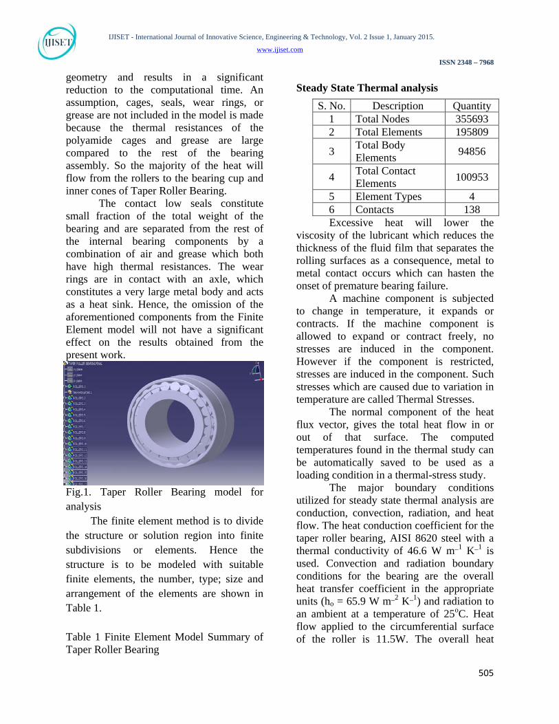
geometry and results in a significant reduction to the computational time. An assumption, cages, seals, wear rings, or grease are not included in the model is made because the thermal resistances of the polyamide cages and grease are large compared to the rest of the bearing assembly. So the majority of the heat will flow from the rollers to the bearing cup and inner cones of Taper Roller Bearing.
The contact low seals constitute small fraction of the total weight of the bearing and are separated from the rest of the internal bearing components by a combination of air and grease which both have high thermal resistances. The wear rings are in contact with an axle, which constitutes a very large metal body and acts as a heat sink. Hence, the omission of the aforementioned components from the Finite Element model will not have a significant effect on the results obtained from the present work.
Fig.1. Taper Roller Bearing model for analysis The finite element method is to divide the structure or solution region into finite subdivisions or elements. Hence the structure is to be modeled with suitable finite elements, the number, type; size and arrangement of the elements are shown in Table 1. Table 1 Finite Element Model Summary of Taper Roller Bearing
Steady State Thermal analysis
Excessive heat will lower the viscosity of the lubricant which reduces the thickness of the fluid film that separates the rolling surfaces as a consequence, metal to metal contact occurs which can hasten the onset of premature bearing failure. A machine component is subjected to change in temperature, it expands or contracts. If the machine component is allowed to expand or contract freely, no stresses are induced in the component. However if the component is restricted, stresses are induced in the component. Such stresses which are caused due to variation in temperature are called Thermal Stresses. The normal component of the heat flux vector, gives the total heat flow in or out of that surface. The computed temperatures found in the thermal study can be automatically saved to be used as a loading condition in a thermal-stress study.
The major boundary conditions utilized for steady state thermal analysis are conduction, convection, radiation, and heat flow. The heat conduction coefficient for the taper roller bearing, AISI 8620 steel with a thermal conductivity of 46.6 W m_1 K_1 is used. Convection and radiation boundary conditions for the bearing are the overall heat transfer coefficient in the appropriate units (ho = 65.9 W m_2 K_1) and radiation to an ambient at a temperature of 25oC. Heat flow applied to the circumferential surface of the roller is 11.5W. The overall heat
S. No. Description Quantity 1 Total Nodes 355693 2 Total Elements 195809
3 Total Body Elements
94856
4 Total Contact Elements
100953
5 Element Types 4 6 Contacts 138
IJISET - International Journal of Innovative Science, Engineering & Technology, Vol. 2 Issue 1, January 2015.
www.ijiset.com
ISSN 2348 – 7968
506
transfer coefficient is applied to the external (exposed) surface of the bearing only.
For analytical calculations in the present work, the specifications and steady state conditions are taken into account. These inputs are considered for thermal analysis and to find out an output. Heat flow directions of the Taper Roller Bearing
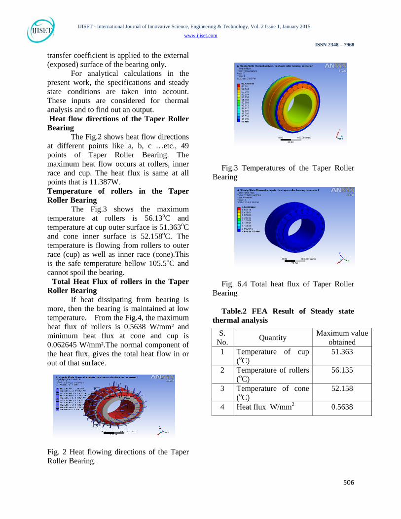
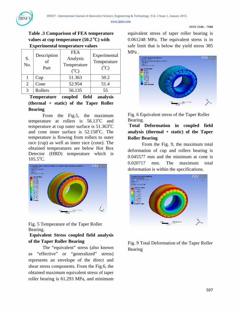
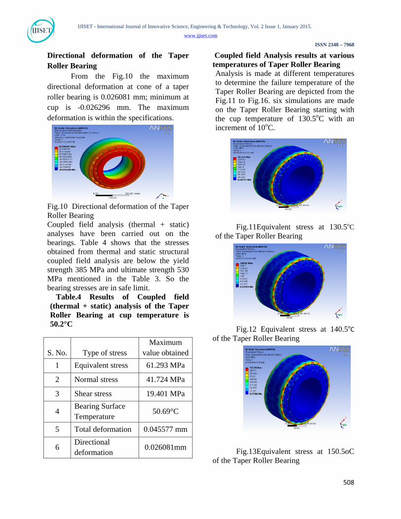
The Fig.2 shows heat flow directions at different points like a, b, c …etc., 49 points of Taper Roller Bearing. The maximum heat flow occurs at rollers, inner race and cup. The heat flux is same at all points that is 11.387W. Temperature of rollers in the Taper Roller Bearing The Fig.3 shows the maximum temperature at rollers is 56.13oC and temperature at cup outer surface is 51.363oC and cone inner surface is 52.158oC. The temperature is flowing from rollers to outer race (cup) as well as inner race (cone).This is the safe temperature bellow 105.5oC and cannot spoil the bearing. Total Heat Flux of rollers in the Taper Roller Bearing If heat dissipating from bearing is more, then the bearing is maintained at low temperature. From the Fig.4, the maximum heat flux of rollers is 0.5638 W/mm² and minimum heat flux at cone and cup is 0.062645 W/mm².The normal component of the heat flux, gives the total heat flow in or out of that surface.
Fig. 2 Heat flowing directions of the Taper Roller Bearing.
Fig.3 Temperatures of the Taper Roller
Bearing
Fig. 6.4 Total heat flux of Taper Roller Bearing
Table.2 FEA Result of Steady state
thermal analysis
S. No.
Quantity Maximum value
obtained 1 Temperature of cup
(oC) 51.363
2 Temperature of rollers (oC)
56.135
3 Temperature of cone (oC)
52.158
4 Heat flux W/mm2 0.5638
IJISET - International Journal of Innovative Science, Engineering & Technology, Vol. 2 Issue 1, January 2015.
www.ijiset.com
ISSN 2348 – 7968
507
Table .3 Comparison of FEA temperature values at cup temperature (50.2 oC) with Experimental temperature values
S. No.
Description of
Part
FEA Analysis
Temperature (oC)
Experimental Temperature
(oC)
1 Cup 51.363 50.2 2 Cone 52.954 51.4 3 Rollers 56.135 55 Temperature coupled field analysis (thermal + static) of the Taper Roller Bearing
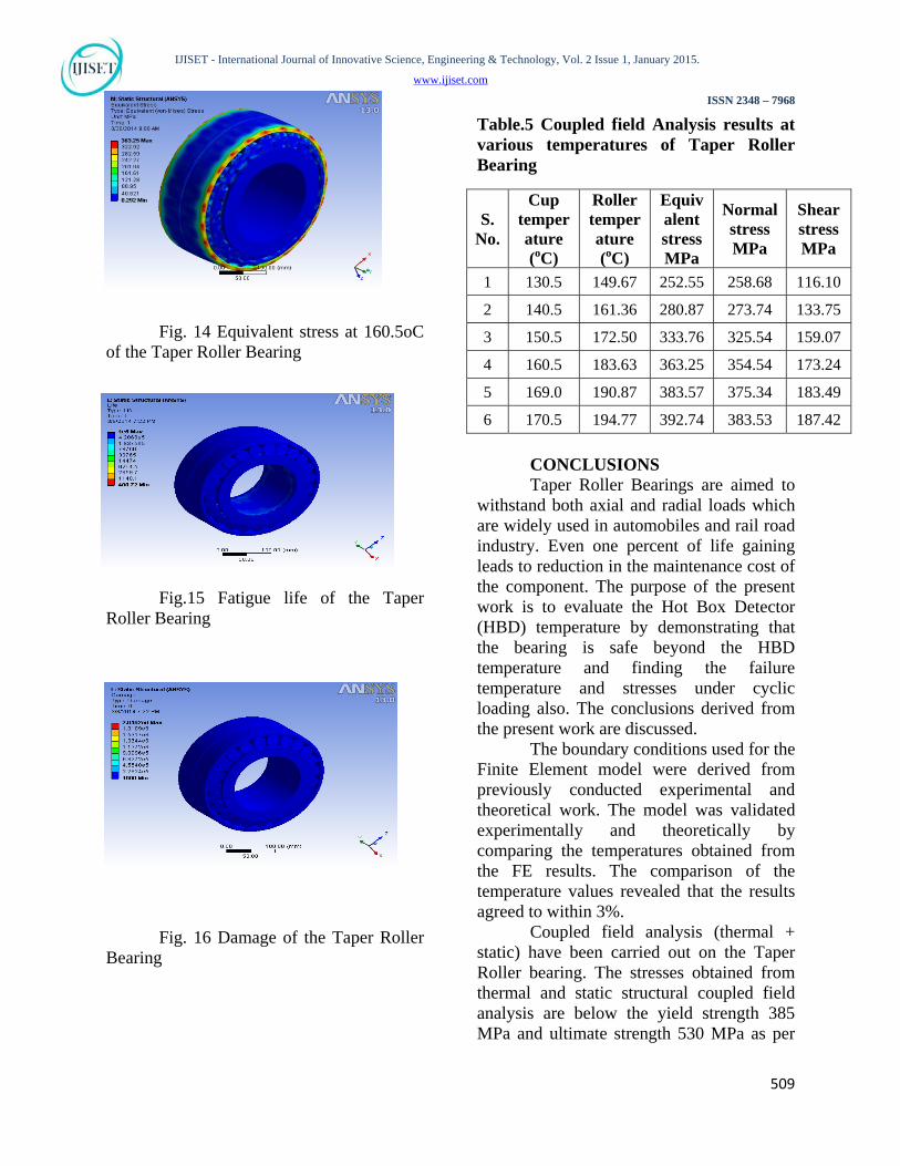
From the Fig.5, the maximum temperature at rollers is 56.13oC and temperature at cup outer surface is 51.363oC and cone inner surface is 52.158oC. The temperature is flowing from rollers to outer race (cup) as well as inner race (cone). The obtained temperatures are below Hot Box Detector (HBD) temperature which is 105.5oC.
Fig. 5 Temperature of the Taper Roller Bearing. Equivalent Stress coupled field analysis of the Taper Roller Bearing
The “equivalent” stress (also known as “effective” or “generalized” stress) represents an envelope of the direct and shear stress components. From the Fig.6, the obtained maximum equivalent stress of taper roller bearing is 61.293 MPa, and minimum
equivalent stress of taper roller bearing is 0.061248 MPa. The equivalent stress is in safe limit that is below the yield stress 385 MPa .
Fig. 6 Equivalent stress of the Taper Roller Bearing. Total Deformation in coupled field analysis (thermal + static) of the Taper Roller Bearing
From the Fig. 9, the maximum total deformation of cup and rollers bearing is 0.045577 mm and the minimum at cone is 0.020717 mm. The maximum total deformation is within the specifications.
Fig. 9 Total Deformation of the Taper Roller Bearing
IJISET - International Journal of Innovative Science, Engineering & Technology, Vol. 2 Issue 1, January 2015.
www.ijiset.com
ISSN 2348 – 7968
508
Directional deformation of the Taper Roller Bearing
From the Fig.10 the maximum directional deformation at cone of a taper roller bearing is 0.026081 mm; minimum at cup is -0.026296 mm. The maximum deformation is within the specifications.
Fig.10 Directional deformation of the Taper Roller Bearing Coupled field analysis (thermal + static) analyses have been carried out on the bearings. Table 4 shows that the stresses obtained from thermal and static structural coupled field analysis are below the yield strength 385 MPa and ultimate strength 530 MPa mentioned in the Table 3. So the bearing stresses are in safe limit. Table.4 Results of Coupled field (thermal + static) analysis of the Taper Roller Bearing at cup temperature is 50.2°C
S. No.
Type of stress
Maximum value obtained
1 Equivalent stress 61.293 MPa
2 Normal stress 41.724 MPa
3 Shear stress 19.401 MPa
4 Bearing Surface Temperature
50.69°C
5 Total deformation 0.045577 mm
6 Directional deformation
0.026081mm
Coupled field Analysis results at various temperatures of Taper Roller Bearing Analysis is made at different temperatures to determine the failure temperature of the Taper Roller Bearing are depicted from the Fig.11 to Fig.16. six simulations are made on the Taper Roller Bearing starting with the cup temperature of 130.5oC with an increment of 10oC.
Fig.11Equivalent stress at 130.5oC of the Taper Roller Bearing
Fig.12 Equivalent stress at 140.5oC of the Taper Roller Bearing Fig.13Equivalent stress at 150.5oC of the Taper Roller Bearing
IJISET - International Journal of Innovative Science, Engineering & Technology, Vol. 2 Issue 1, January 2015.
www.ijiset.com
ISSN 2348 – 7968
509
Fig. 14 Equivalent stress at 160.5oC of the Taper Roller Bearing
Fig.15 Fatigue life of the Taper Roller Bearing
Fig. 16 Damage of the Taper Roller Bearing
Table.5 Coupled field Analysis results at various temperatures of Taper Roller Bearing
CONCLUSIONS Taper Roller Bearings are aimed to
withstand both axial and radial loads which are widely used in automobiles and rail road industry. Even one percent of life gaining leads to reduction in the maintenance cost of the component. The purpose of the present work is to evaluate the Hot Box Detector (HBD) temperature by demonstrating that the bearing is safe beyond the HBD temperature and finding the failure temperature and stresses under cyclic loading also. The conclusions derived from the present work are discussed.
The boundary conditions used for the Finite Element model were derived from previously conducted experimental and theoretical work. The model was validated experimentally and theoretically by comparing the temperatures obtained from the FE results. The comparison of the temperature values revealed that the results agreed to within 3%.
Coupled field analysis (thermal + static) have been carried out on the Taper Roller bearing. The stresses obtained from thermal and static structural coupled field analysis are below the yield strength 385 MPa and ultimate strength 530 MPa as per
S. No.
Cup temperature (oC)
Roller temperature (oC)
Equivalent stress MPa
Normal stress MPa
Shear stress MPa
1 130.5 149.67 252.55 258.68 116.10
2 140.5 161.36 280.87 273.74 133.75
3 150.5 172.50 333.76 325.54 159.07
4 160.5 183.63 363.25 354.54 173.24
5 169.0 190.87 383.57 375.34 183.49
6 170.5 194.77 392.74 383.53 187.42
IJISET - International Journal of Innovative Science, Engineering & Technology, Vol. 2 Issue 1, January 2015.
www.ijiset.com
ISSN 2348 – 7968
510
designer specifications. So the Taper Roller bearing stresses are in safe limit.
Fatigue life analysis of the Taper Roller bearing shows that the bearing has infinite life when the stress is below 86.2 MPa. Since the maximum stress in Taper Roller Bearing is 61.293 MPa (equivalent stress from coupled field analysis), the Taper Roller bearing has infinite life.
Modal analysis of the Taper Roller bearing shows that the natural frequency of designed Taper Roller bearing is 232.92Hz. The bearing working frequency is 9Hz (536/60). So there is no chance to occur resonance because working frequency is less than the natural frequency. The component is safe for dynamic loading.
The results obtained from Transient
Thermal analysis of a taper roller bearing by varying temperature (25°C – 135.33°C) with respect to time 12 hours, the maximum load applied is 159 KN radially. The stresses obtained from Transient thermal and static structural coupled field analysis are below the yield strength 385 MPa and ultimate strength 530 MPa as per the designer specifications. So the bearing stresses are in safe limit. Though the temperatures are higher than the Hot Box Detector (HBD) temperature (105.5°C) the stresses are within the safe limit. Hence one can set the HBD temperature to 120oC (earlier it is 105oC).
REFERENCES [1]. Karunakaran, S., and Snyder, T. W., 2007, “Bearing Temperature Performance in Freight Cars,” Proceedings of the Bearing Research Symposium Sponsored by the AAR Research Program in Conjunction With the ASME RTD 2007 Fall Technical Conference, Chicago, Illinois, Sept. 11–12. [2]. Tarawneh, C. M., Wilson, B. M., Cole, K. D., and Reed, M., 2008, “A Metallurgical and Experimental Investigation Into Sources of Warm Bearing Trending,” Proceedings of
the 2008 IEEE/ASME Joint Rail Conference, Wilmington, DE, Apr. 22–23, paper No. JRC2008–63028. [3]. Tarawneh, C. M., Cole, K. D., Wilson, B. M., and Alnaimat, F., 2008, “Experiments and Models for the Thermal Response of Railroad Tapered- Roller Bearings,” Int. J. Heat Mass Transfer, 51, pp. 5794–5803. [4]. Overstam, H., 2006, “The Influence of Bearing Geometry on the Residual Stress State in Cold Drawn Wire Analyzed by the FEM,” J. Mater. Process. Technol., 171(3), pp. 446–450. [5]. Wei, Y., Qin, Y., Balendra, R., and Jiang, Q., 2004, “FE Analysis of a Novel Roller Form: A Deep End-Cavity Roller for Roller-Type Bearings,” J. Mater. Process. Technol., 145(2), pp. 233–241. [6]. Demirhan, N., and Kanber, B., 2008, “Stress and Displacement Distributions on Cylindrical Roller Bearing Rings Using FEM,” Mech. Based Des. Struct. Mach., 36(1), pp. 86–102. [7]. Vernersson, T., 2007, “Temperatures at Railway Tread Braking. Part 1: Modeling,” Proc. Inst. Mech. Eng., F J. Rail Rapid Transit. 221(2), pp. 167–182. [8]. Schmidt, E., and Weiland, T., 2006, “Application of a Computationally Efficient Air-Gap Element within the Finite Element Analysis of Magnetic Bearings,” IEEE Trans. Magn., 42(4), pp. 1263–1266. [9]. Awasthi, R. K., Jain, S. C., and Sharma, S. C., 2006, “Finite Element Analysis of Orifice-Compensated Multiple Hole-Entry Worn Hybrid Journal Bearing,” Finite Elem. Anal. Des., 42(14/15), pp.1291–1303. [10]. Sukumaran Nair, V. P., and Prabhakaran Nair, K., 2004, “Finite Element Analysis of Elastohydrodynamic Circular Journal Bearing With Micropolar Lubricants,” Finite Elem. Anal. Des., 41(1), pp.75–89. [11]. Dunnuck, D. L., 1992, “Steady-State Temperature and Stack-Up Force
IJISET - International Journal of Innovative Science, Engineering & Technology, Vol. 2 Issue 1, January 2015.
www.ijiset.com
ISSN 2348 – 7968
511
Distributions in a Railroad Roller Bearing Assembly,” M.S. thesis, University of Illinois at Urbana-Champaign, Urbana, IL. [12]. Wang, H., 1996, “Axle Burn-Off and Stack-Up Force Analyses of a Railroad Roller Bearing Using the Finite Element Method,” Ph.D. thesis, University of Illinois at Urbana-Champaign, Urbana, IL. [13]. Wang, S., Cusano, C., and Conry, T. F., 1993, “A Dynamic Model of the Torque and Heat Generation Rate in Tapered Roller Bearings Under Excessive Sliding Conditions,” Tribol. Trans., 36(4), pp. 513–524. [14]. Kletzli, D. B., Cusano, C., and Conry, T. F., 1999, “Thermally Induced Failures in Railroad Tapered Roller Bearings,” Tribol. Trans., 42(4), pp. 824–832. [15]. Farnfield, N. E., 1972, “Thermal Investigations of Roller Bearings,” Tribology, 5(3), p. 104. [16]. Hoeprich, M. R., 1996, “Rolling-Element Bearing Internal Temperatures,” Tribol. Trans., 39(4), pp. 855–858. [17]. Wang, X. L., and Zhu, K. Q., 2006, “Numerical Analysis of Journal Bearings Lubricated With Micropolar Fluids Including Thermal and Cavitating Effects,” Tribol. Int., 39(3), pp. 227–237. [18]. Fillon, M., and Bouyer, J., 2004, “Thermohydrodynamic Analysis of a Worn Plain Journal Bearing,” Tribol. Int., 37, pp. 129–136. [19]. Wang, X. L., Zhu, K. Q., and Wen, S. Z., 2001, “Thermohydrodynamic Analysis of Journal Bearings Lubricated With Couple Stress Fluids,” Tribol. Int., 34, pp. 335–343. [20]. Li, X. K., Davies, A. R., and Phillips, T. N., 2000, “A Transient Thermal Analysis for Dynamically Loaded Bearings,” Comput. Fluids, 29, pp. 749–790. [21]. Ma, M. T., and Taylor, C. M., 1996, “An Experimental Investigation of Thermal Effects in Circular and Elliptical Plain Journal Bearings,” Tribol. Int., 29(1), pp. 19–26.
[22]. Briot, J. M., Bourouga, B., and Bardon, J. P., 1997, “Thermal Transport Conductance Between the Rings of a Roller Bearing,” Rev. Gen. Therm., 36(8), pp. 610–623. [23]. Tarawneh, C. M., Cole, K. D., Wilson, B. M., and Freisen, K., 2007, “A Lumped Capacitance Model for the Transient Heating of Railroad Tapered Roller Bearings,” Proceeding of the 2007 ASEE-GSW Annual conference, March 28–30, Paper No. T2C5. [24]. Tarawneh, C. M., Fuentes, A. A., Wilson, B. M., Cole, K. D., and Navarro, L., 2009, “Thermal Analysis of Railroad Bearings: Effect of Wheel Heating,” Proceedings of the 2009 ASME Joint Rail Conference, Pueblo, CO, March 3–5, Paper No. JRC2009–63055. [25]. Cole, K. D., Tarawneh, C. M., and Wilson, B. M., 2009, “Analysis of Flux- Base Fins for Estimation of Heat Transfer Coefficient,” Int. J. Heat Mass Transfer, 52, pp. 92–99. [26]. Cole, K. D., Tarawneh, C. M., Fuentes, A. A., Wilson, B. M., and Navarro, L., 2010, “Thermal Models of Railroad Wheels and Bearings,” Int. J. Heat Mass Transfer, 53, pp. 1636–1645. [27]. Tarawneh, C. M., Wilson, B. M., Cole, K. D., Fuentes, A. A., and Cardenas, J. M., 2008, “Dynamic Bearing Testing Aimed at Identifying the Root Cause of Warm Bearing Temperature Trending,” Proceedings of the 2008 ASME RTD Fall Technical Conference, Chicago, IL, Sept. 24–26, [28]. Badr, H. M., and Dennis, S. C. R., 1985, “Laminar Forced Convection From a Rotating Cylinder,” Int. J. Heat Mass Transfer, 28(1), pp. 253–264. [29].Kendoush, A. A., 1996, “An Approximate Solution of the Convective Heat Transfer From an Isothermal Rotating Cylinder,” Int. J. Heat Fluid Flow, 17(4), pp. 439–441.