Embed Size (px)
Citation preview

SANDIA REPORT SAND2014-20601 Unlimited Release Printed December 2014
Structural Code Considerations for Solar Rooftop Installations
Stephen F. Dwyer, PhD, PE Brian P. Dwyer Alfred Sanchez
Prepared by Sandia National Laboratories Albuquerque, New Mexico 87185 and Livermore, California 94550
Sandia National Laboratories is a multi-program laboratory managed and operated by Sandia Corporation, a wholly owned subsidiary of Lockheed Martin Corporation, for the U.S. Department of Energy's National Nuclear Security Administration under contract DE-AC04-94AL85000. Approved for public release; further dissemination unlimited.

2
Issued by Sandia National Laboratories, operated for the United States Department of Energy
by Sandia Corporation.
NOTICE: This report was prepared as an account of work sponsored by an agency of the
United States Government. Neither the United States Government, nor any agency thereof,
nor any of their employees, nor any of their contractors, subcontractors, or their employees,
make any warranty, express or implied, or assume any legal liability or responsibility for the
accuracy, completeness, or usefulness of any information, apparatus, product, or process
disclosed, or represent that its use would not infringe privately owned rights. Reference herein
to any specific commercial product, process, or service by trade name, trademark,
manufacturer, or otherwise, does not necessarily constitute or imply its endorsement,
recommendation, or favoring by the United States Government, any agency thereof, or any of
their contractors or subcontractors. The views and opinions expressed herein do not
necessarily state or reflect those of the United States Government, any agency thereof, or any
of their contractors.
Printed in the United States of America. This report has been reproduced directly from the best
available copy.
Available to DOE and DOE contractors from
U.S. Department of Energy
Office of Scientific and Technical Information
P.O. Box 62
Oak Ridge, TN 37831
Telephone: (865) 576-8401
Facsimile: (865) 576-5728
E-Mail: [email protected]
Online ordering: http://www.osti.gov/scitech
Available to the public from
U.S. Department of Commerce
National Technical Information Service
5301 Shawnee Rd.
Alexandria, VA 22312
Telephone: (800) 553-6847
Facsimile: (703) 605-6900
E-Mail: [email protected]
Online order: http://www.ntis.gov/search

3
SAND2014-20601
Unlimited Release
Printed December 2014
Structural Code Considerations for Solar Rooftop Installations
Stephen F. Dwyer, PhD, PE
Geotechnology & Engineering Department
Sandia National Laboratories
P.O. Box 5800
Albuquerque, New Mexico 87185-0706
Brian P Dwyer
Geotechnology & Engineering Department
Sandia National Laboratories
P.O. Box 5800
Albuquerque, New Mexico 87185-0706
Alfred Sanchez, Graduate Research Assistant
Department of Civil Engineering
University of New Mexico
Albuquerque, NM 87131
Abstract
Residential rooftop solar panel installations are limited in part by the high cost of structural
related code requirements for field installation. Permitting solar installations is difficult because
there is a belief among residential permitting authorities that typical residential rooftops may be
structurally inadequate to support the additional load associated with a photovoltaic (PV) solar
installation.
Typical engineering methods used to calculate stresses on a roof structure involve simplifying
assumptions that render a complex non-linear structure to a basic determinate beam. This method
of analysis neglects the composite action of the entire roof structure, yielding a conservative
analysis based on a rafter or top chord of a truss. Consequently, the analysis can result in an
overly conservative structural analysis.
A literature review was conducted to gain a better understanding of the conservative nature of
the regulations and codes governing residential construction and the associated structural system
calculations.

Structural Code Considerations for Solar Rooftop Installations
SAND2014-20601 4 December 2014

Structural Code Considerations for Solar Rooftop Installations
December 2014 5 SAND2014-20601
CONTENTS
Contents ...........................................................................................................................................5
1.0 Introduction .............................................................................................................................7
2.0 Literature Review....................................................................................................................8
2.1 Introduction to Literature Review ............................................................................................... 8
2.2 History of Stress Grading ............................................................................................................ 8
2.3 International Residential Building Code ..................................................................................... 9
2.4 National Design Specification (NDS) ....................................................................................... 11
2.5 ASTM International .................................................................................................................. 13
2.6 USDA Forest Service, Forest Products Laboratory .................................................................. 17
3.0 Summary ...............................................................................................................................19
4.0 References .............................................................................................................................21
Distribution ....................................................................................................................................23
FIGURES Figure 1. Example of prediction of strength by regression analysis. ......................................................... 14
Figure 2. Example of the typical relationship between strength predictor (MOE) and strength (MOR).
Regression line is shifted downwards to below 95% of the data. ............................................... 15
TABLES Table 1. Span Table Adapted from the IRC ............................................................................................... 10
Table 2. Applicability of Adjustment Factors for Sawn Lumber (adapted from NDS). ............................ 11
Table 3. Adjustment Factors To Be Applied To the Clear Wood Properties Provided by ASTM
(adapted from ASTM D245 Table 8) .......................................................................................... 16
Table 4. Example of How ASTM Implements Adjustment Factors for Limiting Characteristics ............. 16
Table 5. Example of ASTM’s Allowable Properties for the Sample Stress-Grade ................................... 17

Structural Code Considerations for Solar Rooftop Installations
SAND2014-20601 6 December 2014
NOMENCLATURE AFPA American Forest & Paper Association
ALS American Lumber Standards
ASD allowable stress design
ASTM American Society for Testing and Materials
FS factor of safety
ICC International Code Council
IRC International Residential Building Code
LRFD load and resistance factor design
MOE modulus of elasticity
MOR modulus of rupture
NDS National Design Specification
PV photovoltaic
USDA United States Department of Agriculture

Structural Code Considerations for Solar Rooftop Installations
December 2014 7 SAND2014-20601
1.0 Introduction
Increased desire to install residential solar photovoltaic (PV) roof systems has prompted a more
detailed structural capacity evaluation of residential roof structures. Permitting authorities
typically default to a conservative view that residential wood roofs may not be able to carry the
additional dead load associated with installing a roof-top PV array. This report looks at the
uncertainty surrounding the International Residential Building Code’s (IRC’s) assumed factor of
safety (FS) in determining safe roof loading. The IRC is prescriptive in nature and consequently
does not account for designs based on material properties and site-specific conditions. Given the
code’s prescriptive nature, the FS is not specified and assumptions regarding system-component
behavior are not offered. This lack of information limits a designer’s understanding of a roof
system’s capacity.
A more comprehensive understanding of residential roofing system capacities to support PV
installations can lead to improved acceptance of roof-top PV installations. Knowledge gained by
empirical testing can support improving the regulatory approval process. Improvements in
regulatory guidance may enhance a regulator’s ability to permit installations without costly
professional engineering certification. These proposed improvements in the permitting process
would clearly lower PV system costs, ultimately resulting in more PV installations.
In 2013, PV system installations nationwide accounted for more than 5,000 MW of new power
generation—of which 16% (800 MW) is within the residential market sector (Solar Energy
Industries Association, 2013). In addition, that 16% increase in PV power generation for
residences corresponds to 90% of all PV installations nationwide. The average residential
installation is 6.2 kW, at an average cost of about $23,000 (Interstate Renewable Energy
Council, 2013). This yields a total cost across the United States for PV residential installations
of 2.4 to 3.5 billion dollars.

Structural Code Considerations for Solar Rooftop Installations
SAND2014-20601 8 December 2014
2.0 Literature Review
2.1 Introduction to Literature Review
At present, residential roof structural engineers use design tables included in the IRC, or
allowable stresses provided by the National Design Specification (NDS) to select or evaluate
roof structure beams. In either case, the FS is not made explicit. This project seeks to assess the
FS built into current design code specifications and make comparisons to our empirical-testing-
derived FS (Dwyer et al 2014, in print).
This report provides a brief history of stress grading; a review of the adopted codes and testing
standards associated with the IRC, the NDS, and the testing standards of American Society for
Testing and Materials International (ASTM); and lastly a review of research conducted at United
States Department of Agriculture (USDA) Forest Service, Forest Products Laboratory.
2.2 History of Stress Grading
The visual stress grading of lumber has existed since the early part of the twentieth century
when, in 1923, the USDA Forest Service Forest Products Laboratory published a set of basic
rules with assigned stress values (Galligan & McDonald, 2000). During World War II these
assigned stress values were increased by 85% as a result of the United States Army dictating an
increase to initial design values as a consequence of the war effort. After the war ended, some of
the changes made by the military became permanent design values. The changes made by the
military and demand for lumber created constant changes to the lumber grading system—and
therefore uncertainty in the design values. To aid the process of creating standard design values
and increase confidence in these values, changes to visual grading procedures came with the
adoption of American Lumber Standards (ALS) PS 20-70. The standards set by the ALS
brought recognition to several factors such as moisture content and shrinkage that influence
grading. Under the ALS, a National Grading Rule was developed (Galligan & McDonald,
2010).
The newly developed grading rule established uniform grading methods that could be applied to
all lumber species. While standardized grading rules now existed, the need to verify baseline
design values was becoming increasingly important. In 1977, the North American In-Grade
Testing Program went into effect in hopes of standardizing design values with the use of proof
testing of full-size samples. As a consequence of such testing, the current visual grading system
can claim to be based on empirical full-scale testing. Due to these empirical tests, changes to
historical design values were made.
Concurrent with standardizing visual grading of lumber, a new method of machine rating was
gaining acceptance within the lumber industry. This new method of machine rating made use of
an observed statistical correlation between stiffness and strength that was found to exist in all
species of wood. By employing this nondestructive machine testing to find a modulus of
elasticity (MOE, i.e., stiffness), the machine rating method was also able to assign an associated
strength or stress grade. As of 1996, the amount of machine stress rated lumber produced in the
United States had increased from insignificant levels of production to 1.1 billion board feet

Structural Code Considerations for Solar Rooftop Installations
December 2014 9 SAND2014-20601
annually (Galligan & McDonald, 2010). Machine stress rated lumber reached an all-time high in
2005, with an estimated production of almost 3 billion board feet (Logan, Allen, Uskoski, &
Nelson, 2010). Currently, it is becoming increasingly difficult to acquire purely visually rated
dimensional lumber as machine-rated lumber allows for higher efficiency in lumber production
and is used almost exclusively.
2.3 International Residential Building Code
One of the most commonly adopted building codes in the United States, the IRC, is authored by
the International Code Council (ICC), which was founded in 1994 by the merger of several
regional councils to form a “comprehensive and coordinated national model of construction
codes” (ICC, 2013 p.7). ICC founding members include three regional councils:
1. the Building Officials and Code Administrators International, Inc., used throughout the east
coast and the midwest portions of the United States;
2. the International Conference of Building Officials, used in the western United States, and;
3. the Southern Building Code Congress International, Inc., implemented in the southern region
of the country.
Predating the ICC, establishing building codes was the responsibility of these three regional
councils and local governments were encouraged to adopt the building codes of the council
nearest in proximity. While the ICC publishes building codes based upon these three regional
councils, a United States governmental-mandated building code does not officially exist. All
fifty states and incorporated municipalities are allowed to adopt codes of their own choosing;
however, most municipalities have partially or fully adopted the IRC codes put forth by the ICC.
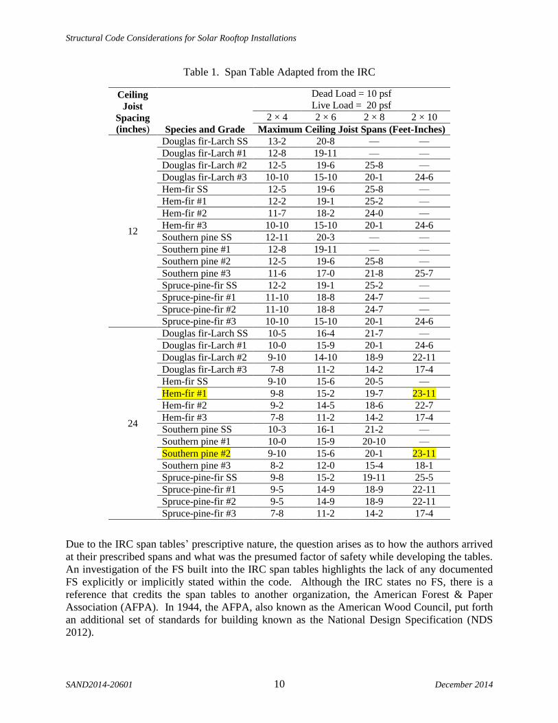
A resource within the IRC are span tables as shown in Table 1, which presents an example of a
span table produced by the IRC. Span tables allow users to choose from several species of
dimensional lumber and from several dead- and live-load combinations to determine the required
lumber dimension for a given span. The IRC also takes into account the spacing between joists,
‘rafter spacing,’ when determining a required span length. With regard to the rafter spacing, the
IRC allows users to choose between four rafter-spacing values: 12", 16", 19.2", and 24" on
center. The four species of lumber listed by the IRC include Douglas fir-larch, hem-fir, southern
pine, and spruce-pine fir. Variations in allowable spans also take into account various grades of
lumber ranging from SS (select structural), #1, #2, and #3. In the IRC, the spans of dimensional
lumber are limited to two dead-loading situations; 10 psf and 20 psf. The IRC also provides four
live-load conditions 20 psf, 30 psf, 50 psf, and 70 psf. As shown by the highlighting in Table 1,
if a user wished to specify a joist that could accommodate a 10 psf dead load with a 20 psf live
load, spanning 23', with a 24" on-center spacing, the code would specify a 2" × 10" Hem-fir #1,
or a 2" × 10" Southern pine #2.
Structural Code Considerations for Solar Rooftop Installations
SAND2014-20601 10 December 2014
Table 1. Span Table Adapted from the IRC
Ceiling
Joist
Spacing
(inches) Species and Grade
Dead Load = 10 psf
Live Load = 20 psf
2 × 4 2 × 6 2 × 8 2 × 10
Maximum Ceiling Joist Spans (Feet-Inches)
12
Douglas fir-Larch SS 13-2 20-8 — —
Douglas fir-Larch #1 12-8 19-11 — —
Douglas fir-Larch #2 12-5 19-6 25-8 —
Douglas fir-Larch #3 10-10 15-10 20-1 24-6
Hem-fir SS 12-5 19-6 25-8 —
Hem-fir #1 12-2 19-1 25-2 —
Hem-fir #2 11-7 18-2 24-0 —
Hem-fir #3 10-10 15-10 20-1 24-6
Southern pine SS 12-11 20-3 — —
Southern pine #1 12-8 19-11 — —
Southern pine #2 12-5 19-6 25-8 —
Southern pine #3 11-6 17-0 21-8 25-7
Spruce-pine-fir SS 12-2 19-1 25-2 —
Spruce-pine-fir #1 11-10 18-8 24-7 —
Spruce-pine-fir #2 11-10 18-8 24-7 —
Spruce-pine-fir #3 10-10 15-10 20-1 24-6
24
Douglas fir-Larch SS 10-5 16-4 21-7 —
Douglas fir-Larch #1 10-0 15-9 20-1 24-6
Douglas fir-Larch #2 9-10 14-10 18-9 22-11
Douglas fir-Larch #3 7-8 11-2 14-2 17-4
Hem-fir SS 9-10 15-6 20-5 —
Hem-fir #1 9-8 15-2 19-7 23-11
Hem-fir #2 9-2 14-5 18-6 22-7
Hem-fir #3 7-8 11-2 14-2 17-4
Southern pine SS 10-3 16-1 21-2 —
Southern pine #1 10-0 15-9 20-10 —
Southern pine #2 9-10 15-6 20-1 23-11
Southern pine #3 8-2 12-0 15-4 18-1
Spruce-pine-fir SS 9-8 15-2 19-11 25-5
Spruce-pine-fir #1 9-5 14-9 18-9 22-11
Spruce-pine-fir #2 9-5 14-9 18-9 22-11
Spruce-pine-fir #3 7-8 11-2 14-2 17-4
Due to the IRC span tables’ prescriptive nature, the question arises as to how the authors arrived
at their prescribed spans and what was the presumed factor of safety while developing the tables.
An investigation of the FS built into the IRC span tables highlights the lack of any documented
FS explicitly or implicitly stated within the code. Although the IRC states no FS, there is a
reference that credits the span tables to another organization, the American Forest & Paper
Association (AFPA). In 1944, the AFPA, also known as the American Wood Council, put forth
an additional set of standards for building known as the National Design Specification (NDS
2012).

Structural Code Considerations for Solar Rooftop Installations
December 2014 11 SAND2014-20601
2.4 National Design Specification (NDS)
While the IRC is a code of prescribed requirements in tabular form, the NDS is numerically
specific with adjustable design values allowing users more specificity in designing members.
The NDS is the preferred code of engineers. As shown in Table 2, adjustment factors are used to
adjust baseline design values to better match site conditions. In order to adjust lumber’s baseline
allowable properties, the NDS provides a table that helps users gather applicable factors and
apply them to a base design value. Developing a design value based on the adjustment factor
approach is shown in Table 2.
Table 2. Applicability of Adjustment Factors for Sawn Lumber (adapted from NDS).
ASD ASD and LRFD LRFD
Load
Dura
tion F
acto
r
Wet
Ser
vic
e F
acto
r
Tem
per
ature
Fac
tor
Bea
m S
tabil
ity F
acto
r
Siz
e F
acto
r
Fla
t U
se F
acto
r
Inci
sing F
acto
r
Rep
etit
ive
Mem
ber
Fac
tor
Colu
mn S
tabil
ity F
acto
r
Buck
ling S
tiff
nes
s F
acto
r
Bea
ring A
rea
Fac
tor
Form
at C
onver
sion
Fac
tor
Res
ista
nce
Fac
tor
Tim
e E
ffec
t F
acto
r
Fb´ = Fb
X CD CM C CL CF Cfu Ci Cr — — — KF b
Ft´ = Ft
X CD CM C — CF — Ci — — — — KF t
Fv´ = Fv
X CD CM C — — — Ci — — — — KF
Fc´ = Fc — CM C — — — Ci — — — Cb KF e
Fc´ = Fc
X CD CM C — CF — Ci — Cp — - KF e
E´ = E
X — CM C — — — Ci — — — — — — —
Emin´ = Emin
X — CM C — — — Ci — — CT — KF —
ASD = allowable stress design, LRFD = load and resistance factor design
The current NDS contains design values for both visually rated lumber and mechanically graded
dimensional lumber. For visually graded lumber, the NDS contains 29 different species of wood
and six corresponding design values for each species. Such design stress values include fiber
bending (Fb), tension parallel to grain (Ft), shear parallel to grain (Fv), compression perpendicular
to grain (Fct), compression parallel to grain (Fc), and MOE (E). Mechanically graded lumber has
tables like those for visually graded lumber; however rather than listing values for every species,
the tables for mechanically graded lumber ignore species type and simply list grades that
correspond to mechanically determined values of E and Fb.

Structural Code Considerations for Solar Rooftop Installations
SAND2014-20601 12 December 2014
While mechanically graded lumber tables still use adjustment factors to arrive at design values,
there is an implicitly generated grade name that is representative of a presumably mechanically
derived E and Fb values. For example, the machine stress rated grade name of 900f-1.0E
corresponds to Fb = 900 psi and E = 1,000,000 psi, Ft = 350 psi, and Fc = 1050. Design values
for machine stress graded lumber rely upon grade types that are presumably found from a
machine test. Variations due to lumber species are not directly addressed within the NDS;
however the notes associated with the design tables state:
for any given bending design value, Fb, the modulus of elasticity, E, and tension
parallel to grain, Ft, design value may vary depending upon species, timber
source or other variables. The “E” and “Ft” values included in the “Fb – E”
grade designations in Table 4c are those usually associated with each Fb level.
Grade stamps may show higher or lower values if machine rating indicates the
assignment is appropriate (NDS, 2012 p. 43).
This note in the design tables casts doubt on the accuracy of the design tables and allows
properties to be changed, presumably based upon the judgment of machine rating operators and
managers. Further doubt is cast upon the accuracy of the design values due to an additional note
that indicates “the gain in load carrying capacity due to increased strength and stiffness resulting
from drying more than offsets the design effect of size reductions due to shrinkage” (NDS
Supplement, 2012 p. 43). This statement highlights that the effect of shrinkage is neglected and
that any change in cross-sectional area is more than counterbalanced by increases in capacity due
to drying. The phrase “more than offsets,” does not quantify the gains in strength due to drying.
Beyond this statement, the NDS provides no further explanation as to the increase in capacity
due to drying effects.
Although the NDS addresses many different properties of wood, the present study mostly
pertains to wood properties associated with bending. Due to this focus, the NDS was examined
with the specific interest in fiber bending strength (Fb). One of the overarching factors affecting
a joist’s strength, and therefore a roof system’s strength, is the system itself. A system’s ability
to resist more load than the sum of its individual components is referred to within the industry as
a system effect. Due to system effects, the NDS allows users to increase a joist’s load-carrying
capacity if it is a member of a composite assembly. The increase in capacity due to system
effects is represented by a ‘repetitive member factor’ (Cr), and provides an increase to allowable
design values of 15% if the joists meet specific requirements. These requirements are stated as
follows:
bending design values Fb, for dimensional lumber 2" to 4" thick shall be
multiplied by the repetitive member factor Cr = 1.15, when such members are
used as joist, truss cords, rafters, studs, planks, decking or similar members which
are in contact or spaced not more than 24" on center; are not less than 3 in
number; and are joined by floor, roof, or other load distributing elements adequate
to support the design load (NDS 2012).
Note that the repetitive member factor, Cr, is a factor that is not influenced by any observed or
measurable characteristic of sawn lumber; but rather the increase in allowable capacity is based
solely on the geometric properties of the assembly, which provide more loading than the sum of
individual components.

Structural Code Considerations for Solar Rooftop Installations
December 2014 13 SAND2014-20601
Unlike the IRC, the NDS provides more design flexibility with variation factors than the IRC
allowing its users the ability to determine the design values that best reflect in situ conditions.
The NDS lacks a stated value for the nominal FS. Furthermore, the NDS casts doubt upon both
the accuracy and final design values by allowing offset of unquantified strength losses, due to
shrinkage, with supposedly greater unquantified strength gains, due to drying.
Ultimately, the NDS provides valuable design information for a wide array of various usages and
types of lumber; however the NDS does not contain enough information to quantify a FS.
Although the NDS does not provide explicit FSs, it does refer users to the ASTM standards and
the North American In-Grade Testing Program. The commentary of the NDS Section 4.2.3.2
states:
Changes in the 1991 NDS to dimension lumber design values are based on a
comprehensive testing program conducted by the North American forest products
industry called In-Grade Testing…. A new test method standard, ASTM D4761,
was developed to cover the mechanical test methods used in the program. A new
standard practice, ASTM D1990, was developed to codify procedures for
establishing design values for visually graded dimension lumber from test results
obtained from in-grade test programs (NDS, 2013).
This new insight into the genesis of design values leads us to investigate the testing procedures
and standards that have been published by the ASTM wood subcommittee D07 and to investigate
the North American In-Grade Testing Program.
2.5 ASTM International
ASTM International publications have greatly influenced the field of structural lumber testing
and current wood design standards. While ASTM once stood for American Society for Testing
and Materials, the current organization does not recognize the acronym and is simply named
ASTM International. The ASTM wood subcommittee (D07) is tasked with the responsibility of
quantifying and documenting testing procedures. To fulfill this responsibility, ASTM
determines the procedures for establishing the mechanical properties of all wood-based products.
As earlier indicated, the NDS specifies some adjustment factors based on various characteristics
of both the material and the systems; however the NDS does not specify how those factors were
found, but rather refers the users to ASTM standards. For example, the addition of a 15%
increase due to repetitive-member performance, stated as appropriate by the NDS stems from
ASTM Standard Evaluating System Effects in Repetitive-Member Wood Assemblies.
The ASTM D6555-03 standard recognizes an increase in load-carrying capacity due to three
factors which include: load sharing, composite action, and residual capacity. Within this
standard, a method for quantifying system effects using empirical test results is presented. The
ASTM standard indicates that at least 28 assemblies need to be tested in order to quantify system
effects (ASTM D6555 Section 8.3). The sample size of 28 specimens stems from ASTM
Standard D2915 titled “Standard Practice for Evaluating Allowable Properties for Grades of
Structural Lumber.” ASTM D 2915 seeks to identify grade assignments based on empirically
derived mechanical properties found during the testing of representative samples. By this

Structural Code Considerations for Solar Rooftop Installations
SAND2014-20601 14 December 2014
standard, a lumber grade can be established which is statistically representative of a sample
population. Due to this representation, ASTM D2915 allows small sample sizes for empirical
testing, thus increasing efficiency for both visually and mechanically graded lumber.
To establish a grade, empirical testing is conducted on a sample size that is representative of the
total population, which ASTM has established at a lower bound of 28. An example of this
process is shown in Figures 1 and 2. After testing is completed, a regression line to the data is
determined. The regression line is then shifted downward to ensure that 95% of the data points
fall above the regression line. This new offset regression line is then said to be indicative of the
population and cutoffs can be established to represent different grades within the entire
population.
Figure 1. Example of prediction of strength by regression analysis.

Structural Code Considerations for Solar Rooftop Installations
December 2014 15 SAND2014-20601
Figure 2. Example of the typical relationship between strength predictor (MOE) and strength
(MOR). Regression line is shifted downwards to below 95% of the data.
In addition to ASTM Standard D2915, machine stress rated lumber is assigned design values
using ASTM Standard D6570 Standard Practice for Assigning Allowable Properties for
Mechanically Graded Lumber, which includes factors aimed at addressing multiple scenarios
and factors including: multiple-member systems, normal duration of load, growth ring position,
moisture content, size factors, different than normal duration of load, decay, treated wood,
temperature, and bearing areas. In addition to discussing these factors and scenarios this ASTM
standard helps to allow nondestructive rating of lumber by relating a physically found MOE to a
hypothetically correlated modulus of rupture (MOR). This hypothetical correlation between
stiffness and bending strength is the basic assumption in nondestructive testing.
In the 1960s, the correlation between MOE and MOR had been recognized, and the lumber
rating industry began to develop machines that could quickly test individual pieces of lumber.
More recent development of these machines incorporates components that not only determine
MOE values but also automatically inspect for visual characteristics such as knots and grain
pattern using optical scanners. These characteristics also influence final grade assignments. Due
to the widespread acceptance of mechanically graded lumber beginning in the 1970s, the vast
majority of all dimensional lumber available today is machine stress rated.
The correlation presented in ASTM Standard D6570 between MOE and MOR provides an
efficient and accurate assignment of grades; however it does not provide explicit information
concerning the FS that is built into the grading system. In the continued search for an established
underlying FS, additional information can be located in ASTM Standard D245 Standard
Practice of Establishing Structural Grades and Related Allowable Properties for Visually
Graded Lumber. Within this standard, the method of establishing allowable properties is
addressed in Section 6.2, which indicates, “properties when divided by the factors given in
Table 8 give the respective allowable design properties for clear straight-grained wood. The

Structural Code Considerations for Solar Rooftop Installations
SAND2014-20601 16 December 2014
factors include an adjustment for normal duration of load and a factor of safety”. Table 3 is an
example of adjustment factors provided by ASTM D245 Table 8.
Table 3. Adjustment Factors To Be Applied To the Clear Wood Properties Provided by ASTM
(adapted from ASTM D245 Table 8)
Adjustment Factors to be Applied to the Clear Wood Properties
B
endin
g
Str
ength
Modulu
s of
Ela
stic
ity i
n
Ben
din
g
Ten
sile
Str
ength
Par
alle
l to
Gra
in
Com
pre
ssiv
e
Str
ength
Par
alle
l to
Gra
in
Hori
zonta
l
Shea
r S
tren
gth
Pro
port
ional
Lim
it a
nd
Str
ess
at
Def
orm
atio
n i
n
Com
pre
ssio
n
Per
pen
dic
ula
r
to G
rain
Softwoods 2.1 0.94 2.1 1.9 2.1 1.67
Hardwoods 2.3 0.94 2.3 2.1 2.3 1.67
Additionally, ASTM D245 provides examples of stress-grade development that clearly show
how adjustment factors affect the overall design values of mechanically and visually rated
lumber. Tables 4 and 5 provide examples of how ASTM implements adjustment factors. ASTM
D245 contains the first explicit mention of a FS, which is an established factor of 2.1. However,
this factor does not apply to all wood properties. As can be seen in Table 3, FSs vary in both
property type and wood classification. It is important to note that any prescribed FS is applied in
addition to the statistical 5% exclusion limit. ASTM D245 also addresses the age of lumber and
its working stress values, indicating that old lumber can be assigned the same working stress
values as new lumber.
Table 4. Example of How ASTM Implements Adjustment Factors for Limiting Characteristics
Selection of Limiting Characteristics
Property Limiting Characteristic
Strength
Ratio %
From
Table
Bending
Narrow face knot = ¾ in 62 2
Knot centerline of wide face = 2⅜ in 60 3
Knot at edge of wide face = 1⅜ in 60 4
Slope of grain 1 in 10 61 1
Compression strength
parallel to grain Knot on any face = 2½ in 61 1
Shear
Slope of grain 1 in 8 66 1
Size of shake or check = ½ in 50 1
Length of end split = 4¼ in 50 1

Structural Code Considerations for Solar Rooftop Installations
December 2014 17 SAND2014-20601
Table 5. Example of ASTM’s Allowable Properties for the Sample Stress-Grade
Allowable Properties for the Sample of Stress-Grade
Property
Strength
Value psi
Adjustment
Factor
Strength
Ratio
Seasoning
Adjustment
Special
Features
Allowable
Property
psi
Bending 4432 1/2.1 0.6 1.25 0.89 1400
Compression
parallel to grain 2174 1/1.9 0.65 1.5 — 1100
Horizontal shear 576 1/2.1 0.5 1.08 — 150
Tension parallel
to grain 4432 1/2.1 0.60 0.55 1.25 — 850
Modulus of
elasticity 1304000 1/0.94 1 1.14 — 1580000
Compression
Perpendicular A
282 1/1.67 1 1.5 — 225
Compression
Perpendicular B
491 1/1.67 1 1.5 — 440
A Compression perpendicular to grain for proportional limit stress.
B Compression perpendicular to grain at 0.04 in (1 mm) deformation.
Out of the three entities providing recommendations to the construction industry, ASTM
standards are the only set of guidelines that provide an explicit FS. In addition to providing a FS,
the ASTM standards provide insight into how grades are assigned using both the correlation
between MOE and MOR and visual inspection. ASTM also has increased the efficiency of
grading lumber by setting standards associated with empirically testing small samples of wood
species to gain knowledge about the larger population.
2.6 USDA Forest Service, Forest Products Laboratory
During the middle of the 20th century, a need developed within the United States lumber
industry to quantify and verify the mechanical properties of various species of 2" thick
dimensional lumber. During that time frame, the bulk of lumber sold in the US was visually
graded, and although machine stress grading standards had already been established, industry
acceptance had not yet been realized. In 1977, in order to verify mechanical properties and
further the accuracy of machine stress grading, the USDA Forest Service’s Forest Products
Laboratory implemented the North American In-Grade Testing Program that included:
Testing of more than 70,000 specimens, totaling approximately 1,000,000 board
feet of lumber, in bending, tension parallel to grain, and compression parallel to
grain. This 10 year, 7 million dollar effort was one of the largest single research
efforts ever undertaken in forest products research (Kretsmann, 2010).
Structural Code Considerations for Solar Rooftop Installations
SAND2014-20601 18 December 2014
The North American In-Grade Testing Program was a coordinated effort that used ASTM
standards to test wood specimens to validate current design standards. The testing program also
helped to establish new standards such as ASTM D 1990 Standard Practice for Establishing
Allowable Properties for Visually Graded Dimensional Lumber from In-Grade Tests of Full Size
Specimens. This standard addresses concerns associated with rapid rates of loading due to
mechanical testing.
To accomplish the task of validating current design values, the North American In-Grade Testing
Program incorporated many local agencies that independently evaluated lumber at a local level.
The In-Grade Testing Program involved 33 species, or species groups, of lumber with
considerations given to several different parameters such as temperature, humidity conditions,
moisture content, and differences in moisture meter reading. The testing program’s goals were
not only to provide mechanical properties of various lumber species but also to produce models
that could be used to predict the strength of light-framed wood assemblies.
The culmination of this research helped to verify many historic lumber design values that had
existed for over seventy years. After the testing was completed in 1988, the results were quickly
adopted by the NDS. The research also helped to adjust behavioral equations for column, beam,
and beam-column design. To this day, the NDS still reflects the results of the North American
In-Grade Testing Program.

Structural Code Considerations for Solar Rooftop Installations
December 2014 19 SAND2014-20601
3.0 Summary
The mechanical properties of sawn lumber have been extensively studied and the methods of
testing wood specimens are well documented. However, questions still remain regarding the
exact testing standards used to develop building codes. This lack of clarity has caused
uncertainty in identifying FSs that exist within the governing codes. From the literature
reviewed it can be concluded that a numerical FS does not actually exist, but rather a range or a
probability of failure would better describe how allowable values have been determined.
Moreover, the added weight applied to a roof system due to a PV installation is not a question of
encroaching on the FSs but rather an issue that must be analyzed as to how it affects the
probability of failure.
In order to further explore the performance of wood roof systems, full-size laboratory testing was
conducted as a means of observing the structural behavior of roof systems (Dwyer et al. 2014, in
print).

Structural Code Considerations for Solar Rooftop Installations
SAND2014-20601 20 December 2014

Structural Code Considerations for Solar Rooftop Installations
December 2014 21 SAND2014-20601
4.0 References 1. American Forest & Paper Association (AF&PA) (2005). National Design Specification for
Wood Construction. American Forest & Paper Association, Inc.
2. American Society of Civil Engineers (ASCE) (2010). Minimum Design Loads for Buildings
and Other Structures. ASCE/SEI 7-10.
3. ASTM Standard D245-00 (2002). Establishing Structural Grades and Related Allowable
Properties for Visually Graded Lumber. ASTM International West Conshohocken, PA, 2003,
DOI: 10.1520/C0033-03A, www.astm.org.
4. ASTM Standard D3498-03 (2011). Standard Specification for Adhesives for Field-Gluing
Plywood to Lumber Framing for Floor Systems. ASTM International West Conshohocken,
PA, 2003, DOI: 10.1520/C0033-03A, www.astm.org.
5. Aune, P. and M. Patton-Mallory. 1986. Lateral load-bearing capacity of nailed joints based
on the yield theory. FPL, RP 470, U.S. Department of Agriculture, Forest Service, Forest
Products Laboratory, Madison, WI.
6. Cramer, S. M., and Wolfe, R. W. (1989) “Load-distribution model for light-frame wood roof
assemblies.” J. Struct. Eng., 2602–2616.
7. Cramer, S. M., Drozdek, J. M., and Wolfe, R. W. (2000). “Load sharing effects in light-
frame wood-truss assemblies.” J. Struct. Eng., 126-12, 1388–1394.
8. Dwyer, S. F., Sandchez, A., Campos, I. A., Gerstle, W. H., and Dwyer, B. (2014).
“Empirically Derived Strength of Residential Roof Structures for Solar Installations.” Sandia
Report, in print.
9. Forest Products Laboratory. (2010). “Wood handbook—Wood as an engineering material.”
General Technical Report FPL-GTR-190. Madison, WI: U.S. Department of Agriculture,
Forest Service, Forest Products Laboratory. 508 p.
10. Foschi, R. O. “Structural analysis of wood floor systems.” J. Struct. Div., ASCE, 108(7),
1557–1574.
11. Gupta, R., Miller, T. H. and Dung, D. (2004). “Practical Solutions to Wood Truss Assembly
Design Problems.” Practice Periodical of Structural Design and Construction, 9(1), pp. 54–
60.
12. “Joints based on the yield theory: Theoretical development.” Research Paper FPL 469, Forest
Products Laboratory, U.S. Dept. of Agriculture, Forest Service, Madison, Wis.
13. Kuenzi, E. W., and Wilkinson, T. L. (1971). “Composite Beams—Effect of Adhesive or
Fastener Rigidity.” Research Paper FPL 152, Forest Products Laboratory, U.S. Dept. of
Agriculture, Forest Service, Madison, Wis.
14. Limkatanyoo P. (2004). “System Behavior of Three-Dimensional Wood Truss Assemblies.”
MS Thesis, Oregon State University, Corvallis, OR, USA.
15. McCutcheon, W. J. (1977). “Method for predicting the stiffness of wood-joist floor systems
with partial composite action.” Research Paper FPL 289, Forest Products Laboratory, U.S.
Dept. of Agriculture, Forest Service, Madison, Wis.
16. McCutcheon, W. J. (1986). “Stiffness of framing members with partial composite action.” J.
Struct. Eng. 112(7), 1623.
17. McCutcheon, W. J. (1984). “Deflection of uniformly loaded floors: A beam-spring analog.”
Research Paper FPL 449, Forest Products Laboratory, U.S. Dept. of Agriculture, Forest
Service, Madison, Wis.

Structural Code Considerations for Solar Rooftop Installations
SAND2014-20601 22 December 2014
18. McLain, T. E. (1975). “Curvilinear load-slip relations in laterally loaded nailed joints.” Ph.D.
thesis, Colorado State University, Fort Collins, CO, USA.
19. Mi, H. (2004). “Behavior of unblocked wood shearwalls.” MScFE thesis. University of New
Brunswick, Fredericton, NB.
20. Mohammad, M. A. H., Smith, I., (1994). “Stiffness of nailed OSB-to-lumber connections.”
Forest Products Journal, 44, 37–44.
21. National Association of Home Builders (NAHB), (2000). Residential Structural Design
Guide: 2000 Edition, Washington, DC.
22. Rancourt, D. G. (2008). “Structural Behavior of Wood I-Joist/OSB Roof Panel Assemblies.”
MS Thesis, University of Maine, Orono, Maine, USA.
23. Rosowsky, D. V., Yu, G. R. (2004). “Partial factor approach to repetitive-member system
factors.” Journal of Structural Engineering-ASCE, 130(11), 1829–1841.
24. Structural Engineers Association of Washington (SEAW), (2009). “Study of Structural
Failures Associated with the Winter 2008–2009 Snow Event in the Spokane/Coeur d’Alene
Area.
25. Thompson, E. G., Vanderbilt, M. D., Goodman, J. R. (1982). “FEAFLO: A program for the
analysis of layered wood systems.” Computers and Structures VII: 237–248; 1977.
26. Varela, I., Campos, A. (2012). “Reconsidering Composite Action on Strength of Wood Roof
Systems.” Thesis, Civil Engineering Department, University of New Mexico.
27. Wang, Q. (2009). “Relationship between fastening properties and load-deflection response of
wood shear walls.” MScFE thesis. University of New Brunswick, Fredericton, NB.
28. Wei-Feng L., Bulleit, W.M. (1995). “Overload behavior of sheathed lumber systems.” J.
Struct. Eng., 121(7), 1110–1118.
29. Wheat, D. L., Vanderbilt, M. D., and Goodman, J. R. (1983). “Wood floors with nonlinear
nail stiffness.” J. Struct. Eng., ASCE, 109(5), 1290–1302.
30. Wilkinson T. L. (1972). “Analysis of nailed joints with dissimilar members.” J. Structural
Div. Amer. Soc. Civil Eng. 98(ST9) 2005–2013. Proc. Pap. 9189.
31. Wilkinson T. L. (1974). “Elastic bearing constants for sheathing materials” Research Paper
FPL 224, Forest Products Laboratory, U.S. Dept. of Agriculture, Forest Service, Madison,
Wis.
32. Wolfe, R. W. (1990). “Performance of light-frame redundant assemblies.” Proc., 1990 Int.
Timber Engineering Conf., 1, 124–131.
33. Wolfe, R. W., and LaBissoniere, T. (1991). “Structural performance of light-frame roof
assemblies. II. Conventional truss assemblies.” Research Paper FPL-RP-499, Forest Products
Laboratory, U.S. Dept. of Agriculture, Forest Service, Madison, Wis.
34. Wolfe, R. W., and McCarthy, M. (1989). ‘‘Structural performance of light-frame roof
assemblies. I: Truss assemblies designed for high variability and wood failure.’’ Research
Paper FPL-RP-492, Forest Products Laboratory, U.S. Dept. of Agriculture, Forest Service,
Madison, Wis.
35. Yu, G. (2003). “Load sharing and system factors for light-frame wall systems.” PhD
dissertation, Oregon State Univ., Corvallis, Oregon.

Structural Code Considerations for Solar Rooftop Installations
December 2014 23 SAND2014-20601
Distribution
1 US DOE Elaine Ulrich EE-2A (electronic copy)
Building LENF950
U.S. Department of Energy
1000 Independence Avenue, SW
Washington, DC, 20585
1 US DOE Christina Nichols EE-3D (electronic copy)
Building LENF950
U.S. Department of Energy
1000 Independence Avenue, SW
Washington, DC, 20585
1 MS0706 Stephen F. Dwyer 6912 (electronic copy)
1 MS0706 Brian P. Dwyer 6912 (electronic copy)
1 MS1137 Geoffrey T. Klise 6926 (electronic copy)
1 MS0899 Technical Library 9536 (electronic copy)

Structural Code Considerations for Solar Rooftop Installations
SAND2014-20601 24 December 2014