Embed Size (px)
Citation preview
Research ArticleStructural Design and Impact Analysis of DeployableHabitat Modules
Yihong Hong ,1,2 Wenjuan Yao ,1 and Yan Xu 3
1Department of Civil Engineering, Shanghai University, Shanghai 200072, China2School of Architectural Engineering, Quzhou University, Zhejiang 324000, China3School of Aeronautics and Astronautics, Zhejiang University, Hangzhou 310027, China
Correspondence should be addressed to Wenjuan Yao; [email protected]
Received 9 March 2018; Accepted 4 July 2018; Published 4 November 2018
Academic Editor: Christopher J. Damaren
Copyright © 2018 Yihong Hong et al. This is an open access article distributed under the Creative Commons Attribution License,which permits unrestricted use, distribution, and reproduction in any medium, provided the original work is properly cited.
Space-deployable habitat modules provide artificial habitable environments for astronauts and will be widely used for theconstruction of future space stations and lunar habitats. A novel structural design concept of space-deployable habitat modulesconsisting of flexible composite shells and deployable trusses has been proposed. Geometric relationships of deployable trussesbased on two types of scissor elements were formulated. Flexible composite shells of space habitat modules were designed, and anonlinear FEA model using ANSYS software was described. Considering folding efficiencies, stiffness, and strength of thestructures, the influences of design parameters were analyzed and the final design scheme of space-deployable habitat moduleswas determined. After detailing the structural designs, low-speed impact dynamic responses between the structures and astainless steel cylinder were simulated. The analysis results show that dynamic responses are only significant at the pointof low-speed impact. The works will provide technical supports for structural designs and engineering applications ofspace-deployable habitat modules.
1. Introduction
Deployable structure technologies have the advantages ofhigh folding efficiencies, light weights, and low constructioncosts, which can be used to build future space antennas andlunar habitats [1, 2]. To solve the problems of high launchcosts and the difficulties in the construction of rigid spacecabins due to their heavy weights and large volumes, therehas been extensive research on the structural technologiesof space-deployable capsules in the United States andEurope, such as that of NASA’s TransHab [3] and the lunarhabitats [4]. In May 2016, the Bigelow Expandable ActivityModule (BEAM) on the International Space Station wasfully expanded, which demonstrates that space-deployablecapsule technology can be successfully applied in spacemissions. Then a series of dynamic tests of BEAM wereconducted to assess how the structure responds to impactsthat cause vibrations and the structure’s ability to dampenthe vibrations.
Most recently published research on deployable lunarhabitats has been focused on structural system and internalspace designs [5], thermal protection system designs [6],structural health monitoring technologies [7], deploymentexperiments [8], high-speed particle impact tests, etc. Thevibration of the space habitat modules occurs during theprocess of in-orbit expansion, changes of orbit, and attitudeadjustments. This vibration is also caused by the influencesof in-orbit environments. To date, the dynamic characteris-tics and dynamic responses of inflatable space modules needto be investigated before these types of structures can besuccessfully implemented by future space missions [9]. Theworks researching the dynamics of inflatable structuresmostly focused on modal analyses. Liu and He [10] analyzedthe dynamic characteristics of inflatable rings in space,considering the material nonlinear characteristics and theinfluences of design parameters. Apedo et al. [11] investigatedthe free vibrations of inflatable beams by using the dynamicstiffness method, taking into account large deformation
HindawiInternational Journal of Aerospace EngineeringVolume 2018, Article ID 3252104, 15 pageshttps://doi.org/10.1155/2018/3252104
and stress stiffening effects of the applied inflation pres-sures, and the results were compared with those from afinite-element analysis in ABAQUS software. The dynamiccharacteristics of space-based inflatable membrane structureswere investigated by Zhang et al. [12]. A dimensional analysiswas employed to reduce the number of independentvariables, and the dimensionless form of the dynamiccharacteristics was obtained. The natural frequencies andthe corresponding modalities of the structures were derivedusing ANSYS software by Miao et al. [13]. The influencesof the structural geometry parameters on the structuralvibration modes were studied.
In spite of the above-mentioned research and develop-ment efforts, structural designs and transient dynamicresponses of space habitat modules still need to be investi-gated and improved. This paper reports a recently conductedeffort that developed an innovative design concept of space-deployable habitat modules consisting of flexible compositeshells and deployable trusses. The structural stiffness of thehabitat modules is improved, and the design concept isintended for large size habitat modules. The dynamicresponses of space-deployable habitat modules need to beinvestigated carefully, which are helpful for the mechanicalperformance evaluation and optimization design of thestructures. The effect of inflatable prestress was consideredin the low-speed impact response analysis.
The remainder of this paper consists of five sections. Sec-tion 2 presents the structural designs of space-deployablehabitat modules. The deployable trusses based on two typesof scissor elements were investigated. A nonlinear FEManalysis model was built using ANSYS software after theflexible composite materials and the load cases weredescribed. Section 3 covers the influence analysis of design
parameters on folding volume and mechanical properties.The final design scheme of space-deployable habitat moduleswas determined. Section 4 describes the low-speed impactdynamic response analysis of space habitat modules causedby the low-speed collisions of a cylindrical colliding object.The dynamic responses of space habitat modules and thecylindrical colliding object during the whole collision processcan be obtained. Finally, Section 5 summarizes the conclud-ing remarks and suggestions for future work.
2. Structural Design of DeployableHabitat Modules
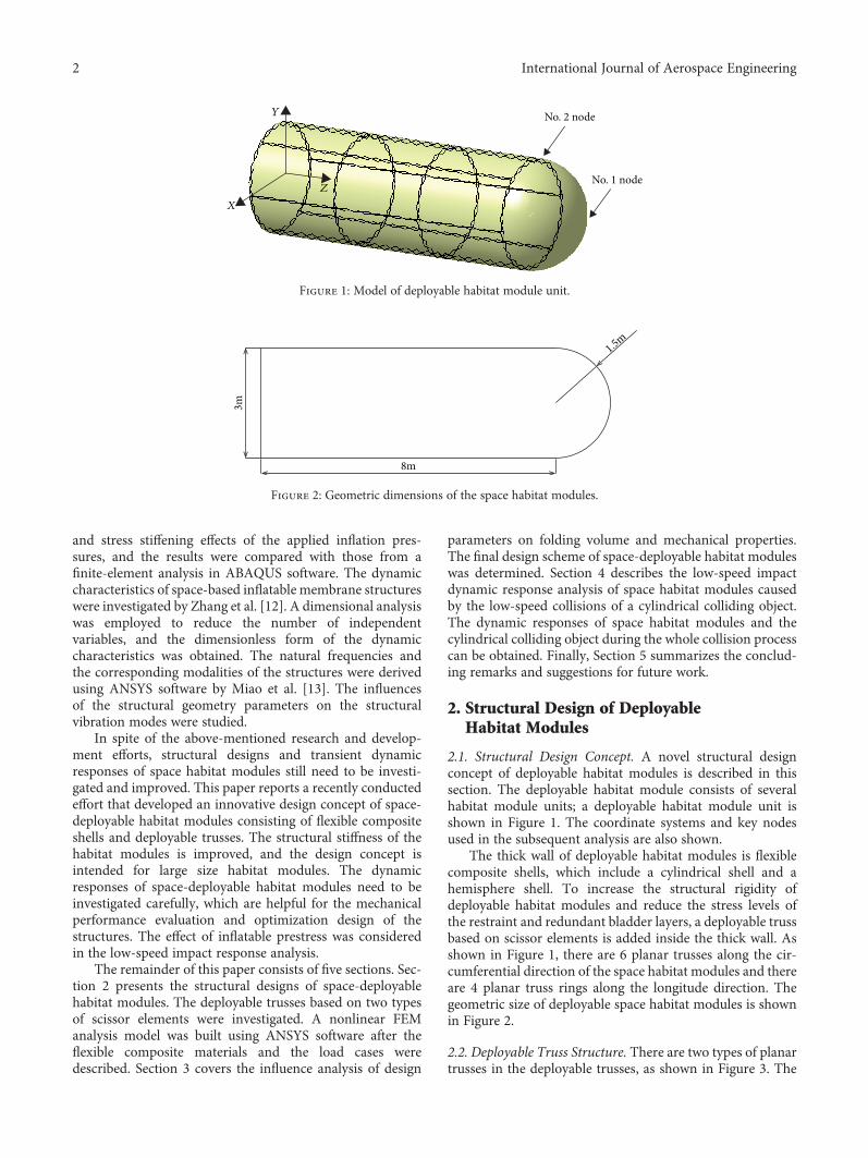
2.1. Structural Design Concept. A novel structural designconcept of deployable habitat modules is described in thissection. The deployable habitat module consists of severalhabitat module units; a deployable habitat module unit isshown in Figure 1. The coordinate systems and key nodesused in the subsequent analysis are also shown.
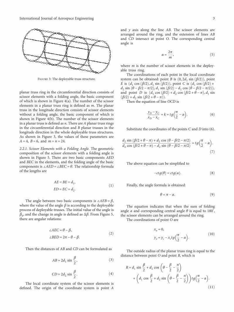
The thick wall of deployable habitat modules is flexiblecomposite shells, which include a cylindrical shell and ahemisphere shell. To increase the structural rigidity ofdeployable habitat modules and reduce the stress levels ofthe restraint and redundant bladder layers, a deployable trussbased on scissor elements is added inside the thick wall. Asshown in Figure 1, there are 6 planar trusses along the cir-cumferential direction of the space habitat modules and thereare 4 planar truss rings along the longitude direction. Thegeometric size of deployable space habitat modules is shownin Figure 2.
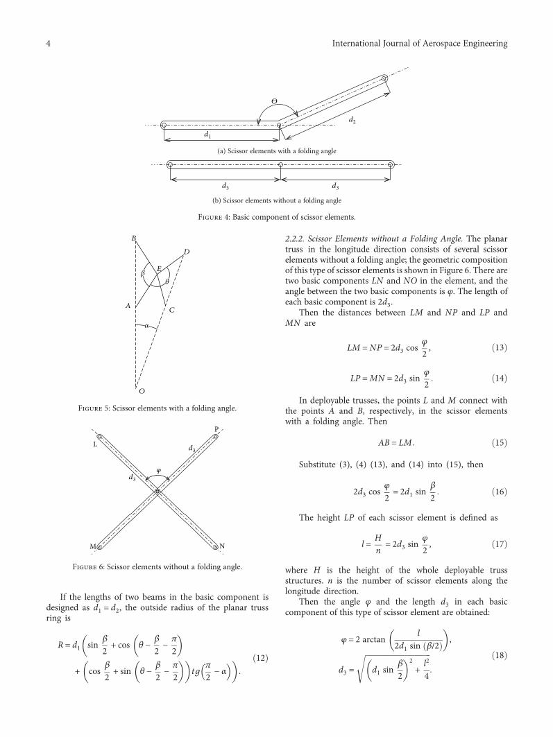
2.2. Deployable Truss Structure. There are two types of planartrusses in the deployable trusses, as shown in Figure 3. The
No. 2 node
No. 1 node
Y
Z
X
Figure 1: Model of deployable habitat module unit.
1.5m
8m
3m
Figure 2: Geometric dimensions of the space habitat modules.
2 International Journal of Aerospace Engineering
planar truss ring in the circumferential direction consists ofscissor elements with a folding angle, the basic componentof which is shown in Figure 4(a). The number of the scissorelements in a planar truss ring is defined as m. The planartruss in the longitude direction consists of scissor elementswithout a folding angle, the basic component of which isshown in Figure 4(b). The number of the scissor elementsin a planar truss is defined as n. There are A planar truss ringsin the circumferential direction and B planar trusses in thelongitude direction in the whole deployable truss structures.As shown in Figure 3, the values of these parameters areA = 4, B = 6, and m = n = 24.
2.2.1. Scissor Elements with a Folding Angle. The geometriccomposition of the scissor elements with a folding angle isshown in Figure 5. There are two basic components AEDand BEC in the elements, and the folding angle of the basiccomponents is ∠AED = ∠BEC = θ. The relationship formulaof the lengths are
AE = BE = d1,ED = EC = d2
1
The angle between two basic components is ∠AEB = β,where the value of the angle β is according to the deployableprocess of deployable trusses. The initial value of the angle isβ0, and the change in angle is defined as Δβ. From Figure 5,there are angular relations:
∠AEC = θ − β,∠BED = 2π − θ − β
2
Then the distances of AB and CD can be formulated as
AB = 2d1 sinβ
2 ,3
CD = 2d2 sinβ
24
The local coordinate system of the scissor elements isdefined. The origin of the coordinate system is point A
and y axis along the line AB. The scissor elements arearranged around the ring, and the extension of lines ABand CD intersect at point O. The corresponding centralangle is
α = 2πm
, 5
where m is the number of scissor elements in the deploy-able truss ring.
The coordinations of each point in the local coordinatesystem can be obtained: point B is 0, 2d1 sin β/2 , pointE is d1 cos β/2 , d1 sin β/2 , point C is d1 cos β/2 +d2 sin θ − β/2 − π/2 , d1 sin β/2 − d2 cos θ − β/2 − π/2 ,and point D is d1 cos β/2 + d2 cos β/2 + θ − π , d1 sinβ/2 + d2 sin β/2 + θ − π .
Then the equation of line OCD is
yD − yCxD − xC
= k = tgπ
2 − α 6
Substitute the coordinates of the points C and D into (6).
d2 sin β/2 + θ − π + d2 cos θ − β/2 − π/2d2 cos β/2 + θ − π − d2 sin θ − β/2 − π/2 = tg
π
2 − α
7
The above equation can be simplified to
−ctg θ = ctg α 8
Finally, the angle formula is obtained:
θ = π − α 9
The equation indicates that when the sum of foldingangle α and corresponding central angle θ is equal to 180°,the scissor elements can be arranged around the ring.
The coordinations of point O are
xo = 0,
yo = yc − xctgπ
2 − α10
The outside radius of the planar truss ring is equal to thedistance between point O and point B, which is
R = d1 sinβ
2 + d2 cos θ −β
2 −π
2
+ d1 cosβ
2 + d2 sin θ −β
2 −π
2 tgπ
2 − α
11
Figure 3: The deployable truss structure.
3International Journal of Aerospace Engineering
If the lengths of two beams in the basic component isdesigned as d1 = d2, the outside radius of the planar trussring is
R = d1 sin β
2 + cos θ −β
2 −π
2
+ cos β
2 + sin θ −β
2 −π
2 tgπ
2 − α
12
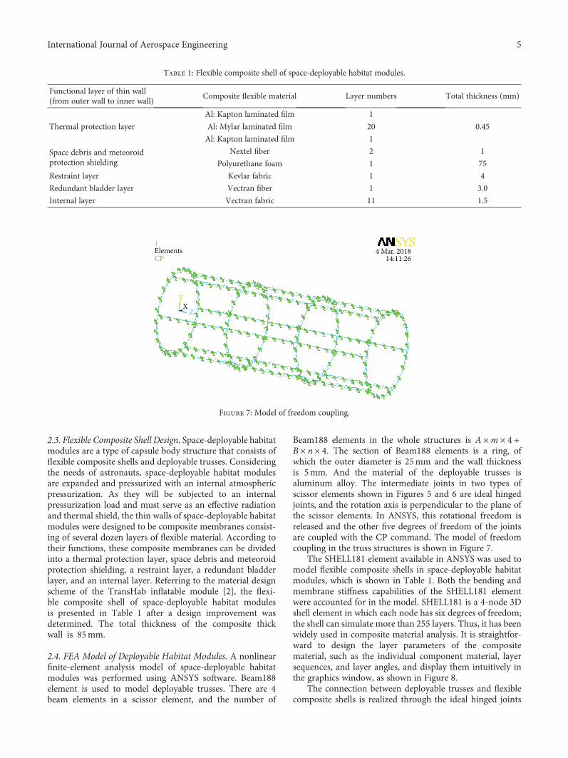
2.2.2. Scissor Elements without a Folding Angle. The planartruss in the longitude direction consists of several scissorelements without a folding angle; the geometric compositionof this type of scissor elements is shown in Figure 6. There aretwo basic components LN and NO in the element, and theangle between the two basic components is φ. The length ofeach basic component is 2d3.
Then the distances between LM and NP and LP andMN are
LM =NP = 2d3 cosφ
2 , 13
LP =MN = 2d3 sinφ
2 14
In deployable trusses, the points L and M connect withthe points A and B, respectively, in the scissor elementswith a folding angle. Then
AB = LM 15
Substitute (3), (4) (13), and (14) into (15), then
2d3 cosφ
2 = 2d1 sinβ
2 16
The height LP of each scissor element is defined as
l = Hn
= 2d3 sinφ
2 , 17
where H is the height of the whole deployable trussstructures. n is the number of scissor elements along thelongitude direction.
Then the angle φ and the length d3 in each basiccomponent of this type of scissor element are obtained:
φ = 2 arctan l2d1 sin β/2 ,
d3 = d1 sinβ
22+ l2
4
18
𝛳
d1
d2
(a) Scissor elements with a folding angle
d3 d3
(b) Scissor elements without a folding angle
Figure 4: Basic component of scissor elements.
A
𝛽
𝛼
𝜃
B
C
D
E
O
Figure 5: Scissor elements with a folding angle.
P
L
NM
d3𝜑
d3
Figure 6: Scissor elements without a folding angle.
4 International Journal of Aerospace Engineering
2.3. Flexible Composite Shell Design. Space-deployable habitatmodules are a type of capsule body structure that consists offlexible composite shells and deployable trusses. Consideringthe needs of astronauts, space-deployable habitat modulesare expanded and pressurized with an internal atmosphericpressurization. As they will be subjected to an internalpressurization load and must serve as an effective radiationand thermal shield, the thin walls of space-deployable habitatmodules were designed to be composite membranes consist-ing of several dozen layers of flexible material. According totheir functions, these composite membranes can be dividedinto a thermal protection layer, space debris and meteoroidprotection shielding, a restraint layer, a redundant bladderlayer, and an internal layer. Referring to the material designscheme of the TransHab inflatable module [2], the flexi-ble composite shell of space-deployable habitat modulesis presented in Table 1 after a design improvement wasdetermined. The total thickness of the composite thickwall is 85mm.
2.4. FEA Model of Deployable Habitat Modules. A nonlinearfinite-element analysis model of space-deployable habitatmodules was performed using ANSYS software. Beam188element is used to model deployable trusses. There are 4beam elements in a scissor element, and the number of
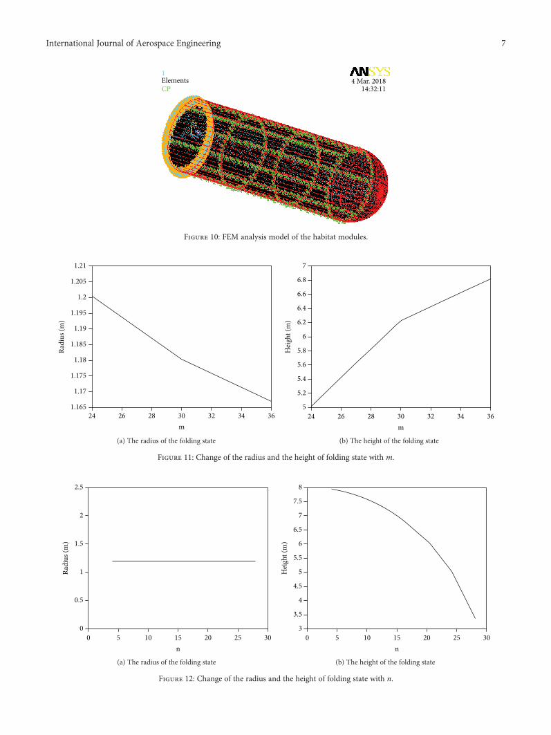
Beam188 elements in the whole structures is A ×m × 4 +B × n × 4. The section of Beam188 elements is a ring, ofwhich the outer diameter is 25mm and the wall thicknessis 5mm. And the material of the deployable trusses isaluminum alloy. The intermediate joints in two types ofscissor elements shown in Figures 5 and 6 are ideal hingedjoints, and the rotation axis is perpendicular to the plane ofthe scissor elements. In ANSYS, this rotational freedom isreleased and the other five degrees of freedom of the jointsare coupled with the CP command. The model of freedomcoupling in the truss structures is shown in Figure 7.
The SHELL181 element available in ANSYS was used tomodel flexible composite shells in space-deployable habitatmodules, which is shown in Table 1. Both the bending andmembrane stiffness capabilities of the SHELL181 elementwere accounted for in the model. SHELL181 is a 4-node 3Dshell element in which each node has six degrees of freedom;the shell can simulate more than 255 layers. Thus, it has beenwidely used in composite material analysis. It is straightfor-ward to design the layer parameters of the compositematerial, such as the individual component material, layersequences, and layer angles, and display them intuitively inthe graphics window, as shown in Figure 8.
The connection between deployable trusses and flexiblecomposite shells is realized through the ideal hinged joints
Table 1: Flexible composite shell of space-deployable habitat modules.
Functional layer of thin wall(from outer wall to inner wall)
Composite flexible material Layer numbers Total thickness (mm)
Thermal protection layer
Al: Kapton laminated film 1
0.45Al: Mylar laminated film 20
Al: Kapton laminated film 1
Space debris and meteoroidprotection shielding
Nextel fiber 2 1
Polyurethane foam 1 75
Restraint layer Kevlar fabric 1 4
Redundant bladder layer Vectran fiber 1 3.0
Internal layer Vectran fabric 11 1.5
XY
Z
1
CP
XY
Z
4 Mar. 201814:11:26
Elements
Figure 7: Model of freedom coupling.
5International Journal of Aerospace Engineering
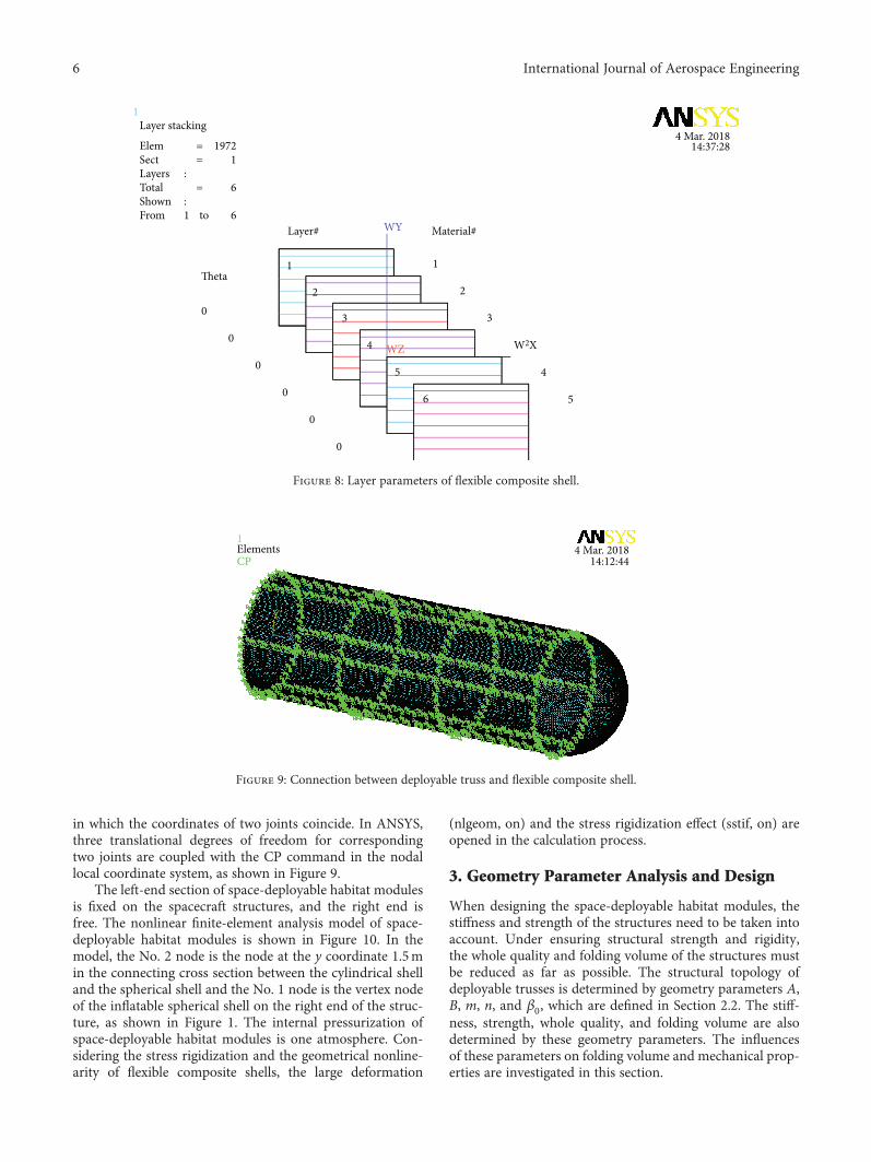
in which the coordinates of two joints coincide. In ANSYS,three translational degrees of freedom for correspondingtwo joints are coupled with the CP command in the nodallocal coordinate system, as shown in Figure 9.
The left-end section of space-deployable habitat modulesis fixed on the spacecraft structures, and the right end isfree. The nonlinear finite-element analysis model of space-deployable habitat modules is shown in Figure 10. In themodel, the No. 2 node is the node at the y coordinate 1.5min the connecting cross section between the cylindrical shelland the spherical shell and the No. 1 node is the vertex nodeof the inflatable spherical shell on the right end of the struc-ture, as shown in Figure 1. The internal pressurization ofspace-deployable habitat modules is one atmosphere. Con-sidering the stress rigidization and the geometrical nonline-arity of flexible composite shells, the large deformation
(nlgeom, on) and the stress rigidization effect (sstif, on) areopened in the calculation process.
3. Geometry Parameter Analysis and Design
When designing the space-deployable habitat modules, thestiffness and strength of the structures need to be taken intoaccount. Under ensuring structural strength and rigidity,the whole quality and folding volume of the structures mustbe reduced as far as possible. The structural topology ofdeployable trusses is determined by geometry parameters A,B, m, n, and β0, which are defined in Section 2.2. The stiff-ness, strength, whole quality, and folding volume are alsodetermined by these geometry parameters. The influencesof these parameters on folding volume and mechanical prop-erties are investigated in this section.
Layer stacking
Elem 1972==Sect 1
1
Layer#
Theta
0
0
0
0
0
0
1
2
3
W2X
WY
4
5
Material#
=Total 6
to 61From
Layers :
Shown :
WZ
4 Mar. 201814:37:28
1
2
3
4
5
6
Figure 8: Layer parameters of flexible composite shell.
XY
Z
1ElementsCP
4 Mar. 201814:12:44
Figure 9: Connection between deployable truss and flexible composite shell.
6 International Journal of Aerospace Engineering
1.21
1.205
1.2
1.195
1.19
1.185
1.18
1.175
1.17
1.16524 26 28 30
m
Radi
us (m
)
32 34 36
(a) The radius of the folding state
7
6.8
6.6
6.4
6.2
6
5.8
5.6
5.4
5.2
524 26 28 30
m32 34 36
Hei
ght (
m)
(b) The height of the folding state
Figure 11: Change of the radius and the height of folding state with m.
XY
Z
1ElementsCP
4 Mar. 201814:32:11
Figure 10: FEM analysis model of the habitat modules.
2.5
2
1.5
1
0.5
00 5 10 15
n20 25 30
Radi
us (m
)
(a) The radius of the folding state
8
7.5
7
6.5
6
5.5
5
4.5
4
3.5
30 5 10 15
n20 25 30
Hei
ght (
m)
(b) The height of the folding state
Figure 12: Change of the radius and the height of folding state with n.
7International Journal of Aerospace Engineering
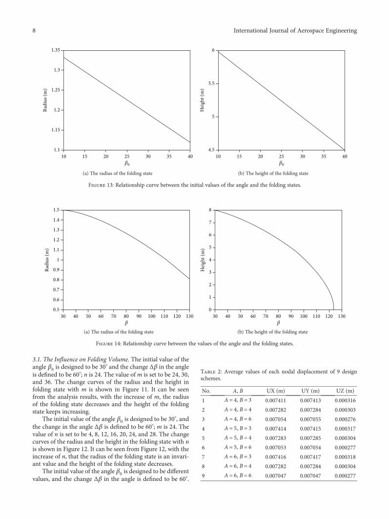
3.1. The Influence on Folding Volume. The initial value of theangle β0 is designed to be 30° and the change Δβ in the angleis defined to be 60°; n is 24. The value of m is set to be 24, 30,and 36. The change curves of the radius and the height infolding state with m is shown in Figure 11. It can be seenfrom the analysis results, with the increase of m, the radiusof the folding state decreases and the height of the foldingstate keeps increasing.
The initial value of the angle β0 is designed to be 30°, and
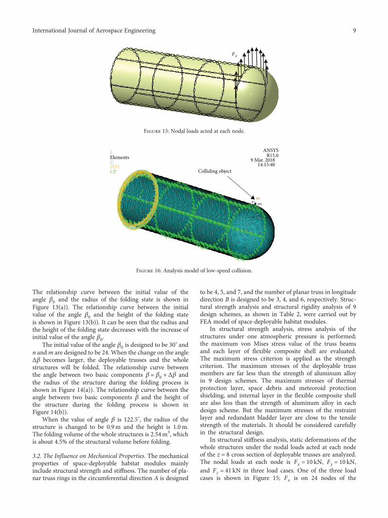
the change in the angle Δβ is defined to be 60°; m is 24. Thevalue of n is set to be 4, 8, 12, 16, 20, 24, and 28. The changecurves of the radius and the height in the folding state with nis shown in Figure 12. It can be seen from Figure 12, with theincrease of n, that the radius of the folding state is an invari-ant value and the height of the folding state decreases.
The initial value of the angle β0 is designed to be differentvalues, and the change Δβ in the angle is defined to be 60°.
1.35
1.25
1.15
1.110 15 20 25
𝛽0
30 35 40
1.3
1.2Radi
us (m
)
(a) The radius of the folding state
6
5.5
5
4.510 15 20 25
𝛽0
30 35 40
Hei
ght (
m)
(b) The height of the folding state
Figure 13: Relationship curve between the initial values of the angle and the folding states.
1.5
30 70 110 120𝛽
130
1.4
1.3
1.2
1.1
1
0.9
0.7
0.5
0.8
0.6
40 50 60 80 90 100
Radi
us (m
)
(a) The radius of the folding state
8
30 70 110 120𝛽
130
7
6
5
4
3
2
1
040 50 60 80 90 100
Hei
ght (
m)
(b) The height of the folding state
Figure 14: Relationship curve between the values of the angle and the folding states.
Table 2: Average values of each nodal displacement of 9 designschemes.
No. A, B UX (m) UY (m) UZ (m)
1 A = 4, B = 3 0.007411 0.007413 0.000316
2 A = 4, B = 4 0.007282 0.007284 0.000303
3 A = 4, B = 6 0.007054 0.007055 0.000276
4 A = 5, B = 3 0.007414 0.007415 0.000317
5 A = 5, B = 4 0.007283 0.007285 0.000304
6 A = 5, B = 6 0.007053 0.007054 0.000277
7 A = 6, B = 3 0.007416 0.007417 0.000318
8 A = 6, B = 4 0.007282 0.007284 0.000304
9 A = 6, B = 6 0.007047 0.007047 0.000277
8 International Journal of Aerospace Engineering
The relationship curve between the initial value of theangle β0 and the radius of the folding state is shown inFigure 13(a)). The relationship curve between the initialvalue of the angle β0 and the height of the folding stateis shown in Figure 13(b)). It can be seen that the radius andthe height of the folding state decreases with the increase ofinitial value of the angle β0.
The initial value of the angle β0 is designed to be 30° andn andm are designed to be 24. When the change on the angleΔβ becomes larger, the deployable trusses and the wholestructures will be folded. The relationship curve betweenthe angle between two basic components β = β0 + Δβ andthe radius of the structure during the folding process isshown in Figure 14(a)). The relationship curve between theangle between two basic components β and the height ofthe structure during the folding process is shown inFigure 14(b)).
When the value of angle β is 122.5°, the radius of thestructure is changed to be 0.9m and the height is 1.0m.The folding volume of the whole structures is 2.54m3, whichis about 4.5% of the structural volume before folding.
3.2. The Influence on Mechanical Properties. The mechanicalproperties of space-deployable habitat modules mainlyinclude structural strength and stiffness. The number of pla-nar truss rings in the circumferential direction A is designed
to be 4, 5, and 7, and the number of planar truss in longitudedirection B is designed to be 3, 4, and 6, respectively. Struc-tural strength analysis and structural rigidity analysis of 9design schemes, as shown in Table 2, were carried out byFEA model of space-deployable habitat modules.
In structural strength analysis, stress analysis of thestructures under one atmospheric pressure is performed;the maximum von Mises stress value of the truss beamsand each layer of flexible composite shell are evaluated.The maximum stress criterion is applied as the strengthcriterion. The maximum stresses of the deployable trussmembers are far less than the strength of aluminum alloyin 9 design schemes. The maximum stresses of thermalprotection layer, space debris and meteoroid protectionshielding, and internal layer in the flexible composite shellare also less than the strength of aluminum alloy in eachdesign scheme. But the maximum stresses of the restraintlayer and redundant bladder layer are close to the tensilestrength of the materials. It should be considered carefullyin the structural design.
In structural stiffness analysis, static deformations of thewhole structures under the nodal loads acted at each nodeof the z = 8 cross section of deployable trusses are analyzed.The nodal loads at each node is Fx = 10 kN, Fy = 10 kN,and Fz = 41 kN in three load cases. One of the three loadcases is shown in Figure 15; Fx is on 24 nodes of the
Fx
Figure 15: Nodal loads acted at each node.
ANSYSR15.0
9 Mar. 2018
Colliding object14:15:40
1
UElements
PDTCP
Figure 16: Analysis model of low-speed collision.
9International Journal of Aerospace Engineering
deployable truss ring. The corresponding nodal displace-ments UX, UY, and UZ of 24 nodes are obtained. Then theaverage values of each nodal displacement are obtained,which are shown in Table 2.
From the analysis results of the structural stiffnessanalysis, the structural stiffness of the x direction is basicallythe same as that in the y direction and less than that in the zdirection in 9 design schemes. The number of planar trussrings in the circumferential direction A has little effect onstructural stiffness. With the increase of parameter B, thestructural stiffness in the three directions increases. Withthe increase of parameters A and B, the whole quality of the
structures increases. So parameter A is designed to be assmall as possible and parameter B is designed to be large.
The analysis results of structural strength and stiffnessare evaluated comprehensively, and the No. 3 designscheme (A = 4, B = 6) is selected finally. The deployabletruss structures corresponding to the No. 3 design schemeis shown in Figure 3.
4. Low-Speed Impact Dynamic Analysis
The space-deployable habitat modules will inevitably collidewith other objects during their service lives, such as the
.8(×10⁎⁎−2)
(×10⁎⁎−3)
.4
0
−.4
−.8
−1.2
Valu
e
−1.6
−2
0 .5 1 1.5 2 2.5 3 3.5 4 4.5 5Time
−2.4
−2.8
−3.2
1POST26UY_2
ANSYSR15.0
9 Mar. 201810:16:35
(a) UY displacement response
1500(×10⁎⁎3)
(×10⁎⁎−3)
1000
500
0
−500
−1000
Valu
e
−1500
−2000
0 .5 1 1.5 2 2.5 3 3.5 4 4.5 5Time
−2500
−3000
−3500
1POST26AY_3
ANSYSR15.0
9 Mar. 201810:20:18
(b) AY acceleration response
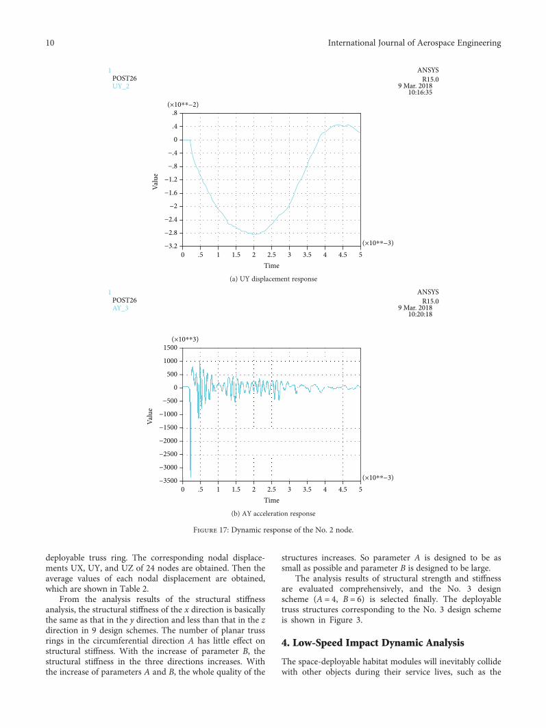
Figure 17: Dynamic response of the No. 2 node.
10 International Journal of Aerospace Engineering
astronauts colliding with the thick walls of the habitationmodules while walking on board or the space manipulatorsystems colliding with the thick walls during the unloadingof supplies or maintenance. This type of collision is a low-speed impact relative to the impacts of space debris. Thepurpose of this section is to describe the analysis model andsimulation results of low-speed impact.
4.1. Analysis Model of Low-Speed Impact. Analysis model oflow-speed impact is shown in Figure 16. The materials andshapes of the actual colliding objects are very complex, so itis assumed that the colliding object is a cylinder with adiameter of 50mm and a height of 100mm. The material ofthe colliding object is stainless steel. In its initial state, thecolliding object impacts outside of the No. 2 node. Thedistance from the colliding object to the outer wall ofspace-deployable habitat modules is 5mm. The collidingobject moves towards the space habitat module at an initialvelocity of 50m/s.
The analysis type is set to be transient, and the FEAmodel of the deployable habitat modules has been describedin detail in Section 2.4. The effect of inflatable prestress isconsidered in the low-speed impact response analysis.To analyze the dynamic responses of the habitat modulesto the low-speed collisions, the SOLID185 element in theANSYS software is used to simulate the cylindrical collidingobject. The CONTA173 and TARGE170 elements are usedto model the contact between the bottom of the cylinderand the outer wall of the space habitat module. The frictionalforce during the contact and collision process is not consid-ered in the analysis model. To reduce the computational cost,the adaptive time step technology used in the solution isadopted. The collision response analysis process is dividedinto four steps: the inflating process, before the collision, dur-ing the collision, and after the collision. The time integral
does not begin during the loading step of the inflating pro-cess. Before the collision, a rigid body displacement of thecylindrical colliding object occurs and a large time step isadopted. The time step size used in the solution processwas [0.0001, 0.0003] s. During and after the collision, a verysmall time step is used such that the calculation time step is[0.000001, 0.00001] s. Total analysis time of the wholecollision process is 0.005 s.
4.2. Dynamic Responses of the Habitat Modules. In theimpact response analysis, the dynamic responses ofspace-deployable habitat modules and the dynamic parame-ters of the cylindrical colliding object during the wholecollision process can be obtained. The UY displacementand AY acceleration responses of the No. 2 node on space-deployable habitat modules are shown in Figure 17. Before0.00020 s, the colliding object moves as a rigid body at aninitial velocity of 50m/s, and no contact occurs between thespace habitat modules and the cylindrical colliding object.Subsequently, a collision occurs between the two objects,and the elastic deformation of the inflatable space habitatmodule appears as a low-speed collision. The UY displace-ment of the No. 2 node reaches a maximum value of28.27mm at approximately 0.00197 s. Then, the collidingobject moves in the reverse direction, and the UY displace-ment of the No. 2 node gradually decreases until the collidingobject separates itself from the space habitat module.Finally, space-deployable habitat modules are left in a stateof free vibrations.
During the whole collision process, the Mises stressresponse time history curve of the No. 1439 element in theflexible composite shells, which is connected to the No. 2node, is as shown in Figure 18. Locations of the No. 1 nodeand No. 2 node are shown in Figure 1. According to theanalysis results, the Mises stress of the No. 1439 element at
8000(×10⁎⁎4)
(×10⁎⁎−3)
7200
6400
5600
4800
4000
Valu
e
3200
2400
0 .5 1 1.5 2 2.5 3 3.5 4 4.5 5Time
1600
800
0
1POST26SEQV_5
ANSYSR15.0
9 Mar. 201810:28:21
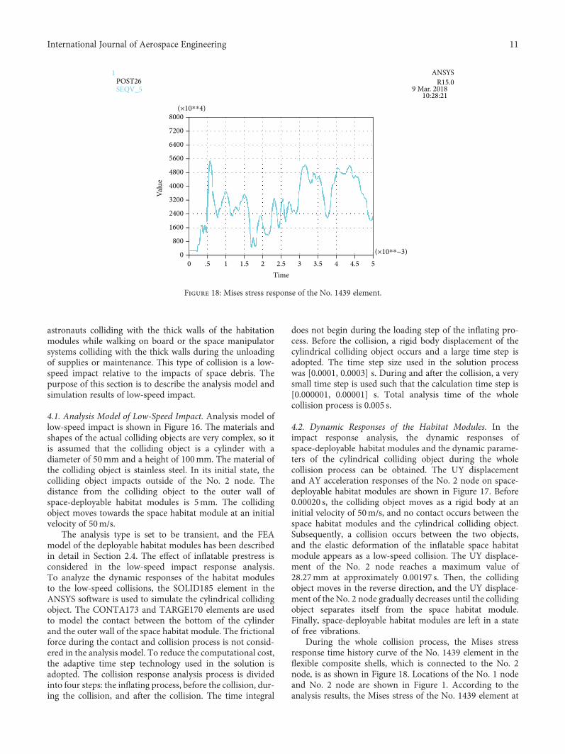
Figure 18: Mises stress response of the No. 1439 element.
11International Journal of Aerospace Engineering
the No. 2 node is approximately 2.94MPa after the inflatingprocess. The first peak value of the Mises stress is 55.1MPaat 0.00057 s, and the second peak value at 0.00317 s is53.08MPa, which occurs during the collision process.Then, the Mises stress of the No. 1439 element changesat the free vibration stage of the inflatable space habitatmodule. The peak values of the Mises stress are smallcompared with the tensile strengths of each layer of compos-ite membranes. During the whole collision process, theflexible composite walls of the space habitat module willnot be destroyed.
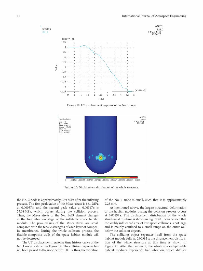
The UY displacement response time history curve of theNo. 1 node is shown in Figure 19. The collision response hasnot been passed to the node before 0.001 s; thus, the vibration
of the No. 1 node is small, such that it is approximately2.25mm.
As mentioned above, the largest structural deformationof the habitat modules during the collision process occursat 0.00197 s. The displacement distribution of the wholestructure at this time is shown in Figure 20. It can be seen thatthe visibly influenced area of low-speed collisions is not largeand is mainly confined to a small range on the outer wallbelow the collision objects.
The colliding object separates itself from the spacehabitat module fully at 0.00382 s; the displacement distribu-tion of the whole structure at this time is shown inFigure 21. After that moment, the whole space-deployablehabitat modules experience free vibration, which diffuses
.25(×10⁎⁎−3)
(×10⁎⁎−3)
0
−.25
−.5
−.75
−1
Valu
e
−1.25
−1.5
0 .5 1 1.5 2 2.5 3 3.5 4 4.5 5Time
−1.75
−2
−2.25
1POST26UY_4
ANSYSR15.0
9 Mar. 201810:36:17
Figure 19: UY displacement response of the No. 1 node.
ANSYSR15.0
9 Mar. 201810:39:05
1Nodal solutionStep =
=====
4181.0019720.03835.03835
SubTimeUsum (AVG)RsysDmxSmx
0 .004261 .008522 .012783 .017045 .021306 .025567 .029828 .034089 .03835
Figure 20: Displacement distribution of the whole structure.
12 International Journal of Aerospace Engineering
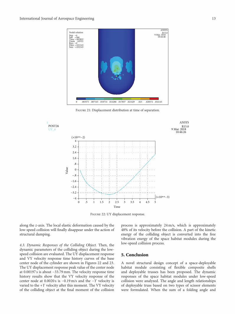
along the z-axis. The local elastic deformation caused by thelow-speed collision will finally disappear under the action ofstructural damping.
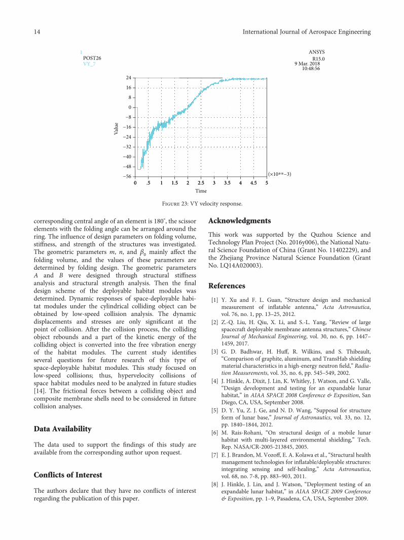
4.3. Dynamic Responses of the Colliding Object. Then, thedynamic parameters of the colliding object during the low-speed collision are evaluated. The UY displacement responseand VY velocity response time history curves of the basecenter node of the cylinder are shown in Figures 22 and 23.The UY displacement response peak value of the center nodeat 0.00197 s is about −33.79mm. The velocity response timehistory results show that the VY velocity response of thecenter node at 0.0020 s is −0.19m/s and the −Y velocity isvaried to the +Y velocity after this moment. The VY velocityof the colliding object at the final moment of the collision
process is approximately 24m/s, which is approximately48% of its velocity before the collision. A part of the kineticenergy of the colliding object is converted into the freevibration energy of the space habitat modules during thelow-speed collision process.
5. Conclusion
A novel structural design concept of a space-deployablehabitat module consisting of flexible composite shellsand deployable trusses has been proposed. The dynamicresponses of the space habitat modules under low-speedcollision were analyzed. The angle and length relationshipsof deployable truss based on two types of scissor elementswere formulated. When the sum of a folding angle and
ANSYSR15.0
9 Mar. 201810:44:46
1Nodal solutionStep =
=====
4366.0038220.032143.032143
SubTimeUsum (AVG)RsysDmxSmx
0 .003571 .007143 .010714 .014286 .017857 .021429 .025 .028572 .032143
Figure 21: Displacement distribution at time of separation.
4
(×10⁎⁎−3)
3.2
2.4
1.6
.8
0
Valu
e
−.8
−1.6
0 .5 1 1.5 2 2.5 3 3.5 4 4.5 5Time
−2.4
−3.2
−4
1POST26UY_6
ANSYSR15.0
9 Mar. 201810:46:26
(×10⁎⁎−2)
Figure 22: UY displacement response.
13International Journal of Aerospace Engineering
corresponding central angle of an element is 180°, the scissorelements with the folding angle can be arranged around thering. The influence of design parameters on folding volume,stiffness, and strength of the structures was investigated.The geometric parameters m, n, and β0 mainly affect thefolding volume, and the values of these parameters aredetermined by folding design. The geometric parametersA and B were designed through structural stiffnessanalysis and structural strength analysis. Then the finaldesign scheme of the deployable habitat modules wasdetermined. Dynamic responses of space-deployable habi-tat modules under the cylindrical colliding object can beobtained by low-speed collision analysis. The dynamicdisplacements and stresses are only significant at thepoint of collision. After the collision process, the collidingobject rebounds and a part of the kinetic energy of thecolliding object is converted into the free vibration energyof the habitat modules. The current study identifiesseveral questions for future research of this type ofspace-deployable habitat modules. This study focused onlow-speed collisions; thus, hypervelocity collisions ofspace habitat modules need to be analyzed in future studies[14]. The frictional forces between a colliding object andcomposite membrane shells need to be considered in futurecollision analyses.
Data Availability
The data used to support the findings of this study areavailable from the corresponding author upon request.
Conflicts of Interest
The authors declare that they have no conflicts of interestregarding the publication of this paper.
Acknowledgments
This work was supported by the Quzhou Science andTechnology Plan Project (No. 2016y006), the National Natu-ral Science Foundation of China (Grant No. 11402229), andthe Zhejiang Province Natural Science Foundation (GrantNo. LQ14A020003).
References
[1] Y. Xu and F. L. Guan, “Structure design and mechanicalmeasurement of inflatable antenna,” Acta Astronautica,vol. 76, no. 1, pp. 13–25, 2012.
[2] Z.-Q. Liu, H. Qiu, X. Li, and S.-L. Yang, “Review of largespacecraft deployable membrane antenna structures,” ChineseJournal of Mechanical Engineering, vol. 30, no. 6, pp. 1447–1459, 2017.
[3] G. D. Badhwar, H. Huff, R. Wilkins, and S. Thibeault,“Comparison of graphite, aluminum, and TransHab shieldingmaterial characteristics in a high-energy neutron field,” Radia-tion Measurements, vol. 35, no. 6, pp. 545–549, 2002.
[4] J. Hinkle, A. Dixit, J. Lin, K. Whitley, J. Watson, and G. Valle,“Design development and testing for an expandable lunarhabitat,” in AIAA SPACE 2008 Conference & Exposition, SanDiego, CA, USA, September 2008.
[5] D. Y. Yu, Z. J. Ge, and N. D. Wang, “Supposal for structureform of lunar base,” Journal of Astronautics, vol. 33, no. 12,pp. 1840–1844, 2012.
[6] M. Rais-Rohani, “On structural design of a mobile lunarhabitat with multi-layered environmental shielding,” Tech.Rep. NASA/CR-2005-213845, 2005.
[7] E. J. Brandon, M. Vozoff, E. A. Kolawa et al., “Structural healthmanagement technologies for inflatable/deployable structures:integrating sensing and self-healing,” Acta Astronautica,vol. 68, no. 7-8, pp. 883–903, 2011.
[8] J. Hinkle, J. Lin, and J. Watson, “Deployment testing of anexpandable lunar habitat,” in AIAA SPACE 2009 Conference& Exposition, pp. 1–9, Pasadena, CA, USA, September 2009.
24
(×10⁎⁎−3)
16
8
0
−8
−16
Valu
e
−24
−32
0 .5 1 1.5 2 2.5 3 3.5 4 4.5 50 .5 1 1.5 2 2.5Time
3 3.5 4 4.5 5
−40
−48
−56
1POST26VY_7
ANSYSR15.0
9 Mar. 201810:48:56
Figure 23: VY velocity response.
14 International Journal of Aerospace Engineering
[9] C. Monticelli, V. Carvelli, Z. Fan, D. Valletti, M. Nebiolo, andA. Messidoro, “Biaxial loading of a textile ribbons structurefor an inflatable module of space habitats,” ExperimentalTechniques, vol. 41, no. 1, pp. 9–17, 2017.
[10] F. Liu and W. He, “Effect of internal gas on modal analysis ofspace-inflatable structure,” Journal of Spacecraft and Rockets,vol. 52, no. 4, pp. 1258–1263, 2015.
[11] K. L. Apedo, S. Ronel, E. Jacquelin, and S. Tiem, “Freevibration analysis of inflatable beam made of orthotropicwoven fabric,” Thin-Walled Structures, vol. 78, pp. 1–15, 2014.
[12] Y. J. Zhang, W. Zhao, and J. Wang, “Analysis of dynamiccharacteristic of space inflatable membrane structures basedon dimensional analysis,” Structure & Environment Engineer-ing, vol. 43, no. 1, pp. 35–40, 2016.
[13] C. Q. Miao, X. T. Li, and H. Ma, “Modal analysis of supportstructure of space inflatable antenna,” Journal of HarbinInstitute of Technology, vol. 37, no. 11, pp. 1589–1591, 2005.
[14] R. B. Malla and T. G. Gionet, “Dynamic response of apressurized frame-membrane lunar structure with regolithcover subjected to impact load,” Journal of Aerospace Engi-neering, vol. 26, no. 4, pp. 855–873, 2013.
15International Journal of Aerospace Engineering

International Journal of
AerospaceEngineeringHindawiwww.hindawi.com Volume 2018
RoboticsJournal of
Hindawiwww.hindawi.com Volume 2018
Hindawiwww.hindawi.com Volume 2018
Active and Passive Electronic Components
VLSI Design
Hindawiwww.hindawi.com Volume 2018
Hindawiwww.hindawi.com Volume 2018
Shock and Vibration
Hindawiwww.hindawi.com Volume 2018
Civil EngineeringAdvances in
Acoustics and VibrationAdvances in
Hindawiwww.hindawi.com Volume 2018
Hindawiwww.hindawi.com Volume 2018
Electrical and Computer Engineering
Journal of
Advances inOptoElectronics
Hindawiwww.hindawi.com
Volume 2018
Hindawi Publishing Corporation http://www.hindawi.com Volume 2013Hindawiwww.hindawi.com
The Scientific World Journal
Volume 2018
Control Scienceand Engineering
Journal of
Hindawiwww.hindawi.com Volume 2018
Hindawiwww.hindawi.com
Journal ofEngineeringVolume 2018
SensorsJournal of
Hindawiwww.hindawi.com Volume 2018
International Journal of
RotatingMachinery
Hindawiwww.hindawi.com Volume 2018
Modelling &Simulationin EngineeringHindawiwww.hindawi.com Volume 2018
Hindawiwww.hindawi.com Volume 2018
Chemical EngineeringInternational Journal of Antennas and
Propagation
International Journal of
Hindawiwww.hindawi.com Volume 2018
Hindawiwww.hindawi.com Volume 2018
Navigation and Observation
International Journal of
Hindawi
www.hindawi.com Volume 2018
Advances in
Multimedia
Submit your manuscripts atwww.hindawi.com