Embed Size (px)
Citation preview

Agricultural Hall and Annex
East Lansing, MI
2005 Senior Thesis
9
Structural Design
Gravity Loads
1- Based on US Standards
Occupancy or Use Uniform (psf) Concentrated (lbs)
Office building
-Office
-Lobbies and first-floor
corridors
-Corridor above first floor
-Partitions
-Superimposed
50
100
80
20
15
2000
2000
2000
2- Based on British Standards
Occupancy or Use Uniform (KN/m2) Concentrated
-General Office
-Partitions
2.5 KN/m2(52.2 psf)
1 KN/ m2(20.5 psf)
2.7 KN ( 607 lbs)
Load Combinations
Based on US Standards
1- U = 1.4(D+F)
2- U = 1.2(D+F+T) + 1.6 (L+H) + 0.5 (Lr or S or R)
3- U = 1.2D + 1.6(Lr or S or R) + (1.0l or 0.8W)
4- U = 1.2D + 1.6W + 1.0L +0.5(Lr or S or R)
5- U = 1.2D + 1.0E+ 1.0L + 0.2S
6- U = 0.9D +1 .6W + 1.6H
7- U = 0.9D + 1.0 E + 1.6 H
Based on British Standards
Condition
Dead + imposed load
( + earth pressure)
1.4 Gk + 1.6 Qk + 1.4 En
Dead + wind load
( + earth pressure)
1.4 ( Gk + Wk + En)
Design
loads
Dead + imposed + wind
load (+ earth pressure)
1.2 ( Gk + Qk + Wk + En)

Agricultural Hall and Annex
East Lansing, MI
2005 Senior Thesis
10
Framing Systems
All the gravity systems except the one-way skip joist were designed using
equivalent frame method as it is described below. ADOSS was used to design the flat
slab with drop panels systems and the two-way slab with beams since it uses equivalent
frame method in the design.
Equivalent Frame Method (EFM)
According to ACI 318-02
13.7: The equivalent frame method involves the representation of the three-dimensional
slab system by a series of two-dimensional frames that are then analyzed for loads
acting in the plane of the frames. The negative and positive moments are
determined at the critical sections of the frame and then distributed to the slab
sections: column strips, beams if used, and middle strips. The equivalent frame
consists of three parts: Slab beams, columns, and torsional members.
13.7.2: Equivalent Frame
Each frame contains a row of columns and broad continuous beams. The beams or
slab beam includes the portion of the slab bounded by panel centerline on either
side of the column, together with the column-line beams or drop panel if used.
For the vertical loading, each floor with its columns may be analyzed separately.
It is convenient and sufficiently accurate to assume that the continuous frame is
completely fixed at support when computing the bending moment at the support.
Frames adjacent and parallel to an edge shall be bounded by the edge and the
centerline of adjacent panel.
Each frame can be analyzed separately.
13.7.3: Slab-beams
It is permitted to use the gross area of concrete when computing the moment of
inertia of slab-beams at any cross section outside of joints or column capitals.
Variation in moment of inertia along axis of slab-beams shall be taken into
account.
Moment of inertia of slab-beams from center of column to face of column,
bracket, or capital shall be assumed equal to the moment of inertia of the slab-
beam at face of column, bracket divided by (1-c2/l2)2.
13.7.4: Column
It is permitted to use the gross area of concrete when computing the moment of
inertia of slab-beams at any cross section outside of joints or column capitals
Variation in moment of inertia along axis of slab-beams shall be taken into
account.

Agricultural Hall and Annex
East Lansing, MI
2005 Senior Thesis
11
Moment of inertia of columns from top to bottom of the slab-beam at a joint shall
be assumed to be infinite.
13.7.5: Torsional Members
Tensional members shall be assumed to have a constant cross section throughout
their length consisting of the largest of: 1- portion of slab having a width equal to
column/capital width, 2- same portion of slab + transverse beam, or 3- transverse
beam.
Equivalent Frame Analysis by Computer
The EFM is oriented toward analysis using the method of moment distribution.
Plane frame analysis programs can be used for slab analysis based on the concepts of the
equivalent frame method, but the frame must be specially modeled. Variable moments of
inertia along the axis of slab-beams and columns require nodal points (continuous joints)
between sections where I is to be considered constant. It is also necessary to compute Kec
for each column, and then to compute the equivalent value of the moment of inertia for
the column. Alternately, a three-dimensional frame analysis maybe used in which the
torsional properties of the transverse supporting beam may be included directly. The third
option is to make used of specially written computer programs. The most widely used
program is Analysis and Design of Reinforced Concrete Slab System, ADOSS,
developed by Portal Cement Association (Nilson, Darwin, and Dolan, 2002). All the
systems for the submission are designed using ADOSS.
ADOSS Analysis
Procedure Steps
1- Enter project name and span ID
2- Choose type of slab and frame location, either exterior of interior
3- Number of spans. Spans are measured from center of column to center of
column. For 3 spans building, number of spans are 5 because ADOSS
considers the projection after column line as cantilever. Also, minimum slab
thickness is entered.
4- Choose material properties: 150 pcf for density, 4 ksi for f’c, and 60 ksi for fy.
5- Enter slab reinforcement data, can either be accepted or changed if desired.
6- Enter slab geometry. For the end span, the length is equal to the ½ column
width.
7- Enter column information, c1, c2, and column height above and below slab.
This is just an initial estimate for column size. All the columns have the same
sizes. Yet, they can be changed if required.
8- Enter the initial size of transverse beams for the end spans or middle spans.
Also the right eccentricity value must be entered so the beams edges coincide
with column and slab edges.

Agricultural Hall and Annex
East Lansing, MI
2005 Senior Thesis
12
9- Enter LL and DL loads. The dead load is only the superimposed load. Partial
loads can be entered as well if any.
10- Load factors can be changed if desired.
11- Column fixity factor is 100 %
12- Finally, design the system.
13- Check if everything is ok with the design such as shear, and deflection.
14- Redesign the system if necessary such as increasing slab thickness, and drop
panel thickness.
15- Redesign the system
16- Check the system to make sure that everything is ok.
ADOSS load patterns:
1- Full dead and 75 % live on adjacent spans
2- Full dead and 75 % live on odd-numbered spans.
3- Full dead and 75 % live on even-numbered spans
4- Full dead and full live on all spans
Wide-Module Concrete Joist System (Skip Joist System)
Skip Joist System is widely known as Wide-Module Concrete Joist System which
a joist system is having clear spacing between ribs of more than 30”. Skip Joist is
basically designed as T-beams according to ACI 8.10.
Maximum Bar size for single bars in the bottom of a wide-module joist rib
Rib Width at Bottom Stirrup
Style
No. of Bars
6” 7” 8” 9” 10”
2 #6 #9 #11 #14 #14 J
3 - #4 #6 #8 #10
2 #4 #8 #10 #11 #14 U
3 - - #5 #8 #9
Maximum Bar size for 2-bar bundles in the bottom of a wide-module joist rib
Rib Width at Bottom Stirrup
Style
No. of Bars
6” 7” 8” 9” 10”
1 #9 #11 #11 #11 #11 J
2 #3 #5 #6 #8 #9
1 #8 #11 #11 #11 #11 U
2 - #4 #5 #7 #8

Agricultural Hall and Annex
East Lansing, MI
2005 Senior Thesis
13
Design Consideration
1- ACI 7.7.1: Minimum concrete cover: 1 ½ in to stirrups and main flexural bars.
2- ACI 11.3.1.1: Design shear strength: Vc = 2 f’c bw d
3- ACI 11.5.5.3: Minimum shear reinforcement: Av= 50(bws)/fy
4- Reinforcing steel requirements and recommended details
Figure 3 Figure 4
Figure 5

Agricultural Hall and Annex
East Lansing, MI
2005 Senior Thesis
14
Figure 6 – Bar cutoff for Wide-Module One way Joist
Openings in Slab Systems
Based on US and British Standards
Since all my openings are large and interrupt the steel reinforcement in the
column strips, beams shall be designed around the openings to meet the design strength
and ductility requirements.
Deflection Check
For each designed system, the deflection was checked to make sure that it does
not exceed the maximum deflection that is set by the US or British Standards. All the
deflections that were obtained are mentioned later in the report. The material and
reinforcement properties are given below. Appendix A has all the maximum deflections
allowed by both US and British Standards.
Material Properties and Reinforcement
CONCRETE FACTORS SLABS BEAMS COLUMNS
DENSITY(pcf ) 150.0 150.0 150.0
TYPE NORMAL WGT NORMAL WGT NORMAL WGT
f'c (ksi) 4.0 4.0 4.0
fct (psi) 423.7 423.7 423.7
fr (psi) 474.3 474.3 474.3
REINFORCEMENT DETAILS: NON-PRESTRESSED
YIELD STRENGTH (flexural) Fy = 60.00 ksi
YIELD STRENGTH (stirrups) Fyv = 60.00 ksi
DISTANCE TO RF CENTER FROM TENSION FACE:
AT SLAB TOP = 1.50 in OUTER LAYER
AT SLAB BOTTOM = 1.50 in OUTER LAYER

Agricultural Hall and Annex
East Lansing, MI
2005 Senior Thesis
15
AT BEAM TOP = 1.50 in OUTER LAYER
AT BEAM BOTTOM = 1.50 in
FLEXURAL BAR SIZES: MINIMUM | MAXIMUM
AT SLAB TOP = # 4
AT SLAB BOTTOM = # 4
AT BEAM TOP = # 4 #14
IN BEAM BOTTOM = # 4 #14
MINIMUM SPACING:
IN SLAB = 6.00 in
IN BEAM = 1.00 in

Agricultural Hall and Annex
East Lansing, MI
2005 Senior Thesis
16
Wide Module One-way Joist
The wide module one-way joist system for the Agricultural Hall and Annex is
designed using the CRSI Handbook. There were several trials of wide module joists in
order to match the depth of the girder with the depth of the joist for more economical
system and efficient system. The best joist that matched the girder’s depth is 66” Forms +
6” Ribs @ 72 c.-c, the total depth = 24.5 in (20” Deep Rib + 4.5” Top Slab). All the
girders have the same depth as the joists.
For the End Span
Tabulated Capacity 1002 plf
Top Bars # 4 at 10 in
Bottom Bars 2 # 7
Stirrups Single leg stirrups, # 3 spaced at 11 in for 123 in
For the Interior Span
Tabulated Capacity 1774 plf
Top Bars # 5 at 11 in
Bottom Bars 2 # 7
Stirrups Single leg stirrups, # 3 spaced at 11 in for 125 in
Concrete Quantity = 497 plf = 497/ (72”/12”) = 83 psf
Deflection:
CRSI: the computation of deflection is not required above the horizontal line (thickness
ln/18.5 for end spans, ln/21 for interior spans)

Agricultural Hall and Annex
East Lansing, MI
2005 Senior Thesis
17
Figure 7

Agricultural Hall and Annex
East Lansing, MI
2005 Senior Thesis
18
Flat Slab with Drop Panel Design Summary (US Standard)
Flat Slab with Drop Panels (US Standards)
Item Value Comment
Slab thickness 12.5” > Minimum
Drop panel thickness 3.5 > ¼ slab thickness
Drop panel size 10 ft2
Allowable shear stress 252.96 psi
Maximum shear 245.52 psi << Allowable
Maximum joint moment 945’ kip
Maximum joint shear 169 psi
Maximum deflection 0.266 in << Allowable
Figure 8

Agricultural Hall and Annex
East Lansing, MI
2005 Senior Thesis
19
Figure 9 – E-W Reinforcement for Flat Slab (US Standards)
Agricultural Hall and Annex
East Lansing, MI
2005 Senior Thesis
20
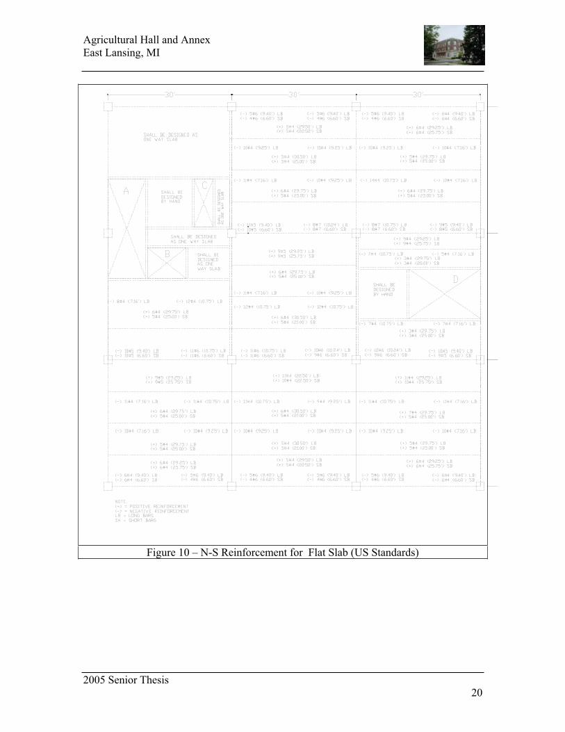
Figure 10 – N-S Reinforcement for Flat Slab (US Standards)

Agricultural Hall and Annex
East Lansing, MI
2005 Senior Thesis
21
Two-way Slab with Drop Panels (British Standards)
Two-way Slab with Drop Panels (British Standards)
Item Value Comment
Slab thickness 13.0” > Minimum
Drop panel thickness 3.5” > ¼ slab thickness
Drop panel size 10 ft2
Allowable shear stress 252.96 psi
Maximum shear 245.25 psi << Allowable
Maximum joint moment 1040’ kip
Maximum joint shear 184 psi
Maximum deflection 0.235 in << Allowable
Figure 11

Agricultural Hall and Annex
East Lansing, MI
2005 Senior Thesis
22
Figure 12 – E-W Reinforcement for Flat Slab (British Standards)

Agricultural Hall and Annex
East Lansing, MI
2005 Senior Thesis
23
Figure 13 – N-S Reinforcement for Flat Slab (British Standards)

Agricultural Hall and Annex
East Lansing, MI
2005 Senior Thesis
24
Two-way Slab with Beams (British Standards)
Two-way Slab with Beams (Oman)
Item Value Comment
Slab thickness 10.5”
Drop panel thickness 3.5” > ¼ slab thickness
Drop panel size 10 ft2
Allowable shear stress 252.96 psi
Maximum shear 252.69 psi << Allowable
Maximum joint moment 1040’ kip
Maximum joint shear 185 psi
Maximum deflection 0.236 in << Allowable
Figure 14

Agricultural Hall and Annex
East Lansing, MI
2005 Senior Thesis
25
Figure 15

Agricultural Hall and Annex
East Lansing, MI
2005 Senior Thesis
26
Figure 16 - Two-way Slab with Beams Reinforcement (E-W) (British Standards)
Agricultural Hall and Annex
East Lansing, MI
2005 Senior Thesis
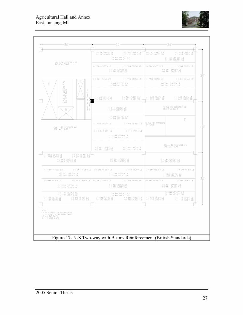
27
Figure 17- N-S Two-way with Beams Reinforcement (British Standards)
![8 PSF.. PSF.., PSKF.., PSBF..166 Каталог Œ Низколюфтовые мотор-редукторы с серводвигателем (bsf.., psf..) psf.. ds../cm.. [nm] psf](https://img.pdfslide.net/doc/110x75/60aae1c0b44f99541163ed48/8-psf-psf-pskf-psbf-166-f.jpg)