Embed Size (px)
Citation preview
Structural Design of an Ultra High-rise Building
Using Concrete Filled Tubular Column
with Ultra High Strength Materials
M. S. Matsumoto, K. T. Komuro, N. H. Narihara, K. S. Kawamoto
& H. O. Hosozawa Taisei Corporation,Tokyo, Japan
M. K. Morita Emeritus Professor of Chiba University,Chiba, Japan
SUMMARY:
Nowadays, structural needs for ultra high-rise buildings are changing and expansion of planning flexibility is
becoming significant. For example, long- span girders for large workspace, altering column position in middle
stories to achieve different use in height direction and great public atrium in lower stories that provides attractive
free space. Moreover, high seismic performance is becoming more demanded which protects human life and
maintains the function of the building under severe earthquakes. In order to achieve these needs, as one of
technology, we have developed ultra high strength concrete filled tubular (CFT) columns that combine ultra high strength concrete with specified standard strength Fc150N/mm2 and ultra high strength steel material with tensile strength of 780N/mm2 . In this paper, the outline of development of a ultra high strength CFT column is reported.
Also, the structural design of the ultra high-rise building using the CFT columns is reported.
Keywords: Concrete filled tubular column, Ultra high strength steel and concrete, Ultra high-rise building
1. INTRODUCTION
In recent ultra high-rise buildings, there are many cases where large spans are required to gain spacial
freedom on typical floors and wide atria to allow continuity with the external spaces on the lower floors. In order to achieve these spaces, it is necessary to provide high strength in the structural
members that constitute the building structure, particularly the columns. It is possible to avoid
excessively large volume columns by using appropriate combinations of high strength materials. Therefore we have developed ultra high strength concrete filled tubular (CFT) columns that combine
ultra high strength concrete with specified strength Fc150N/mm2 and ultra high strength steel
material with tensile strength of 780N/mm2 (Sato et. al., 2009), (Morita et. al., 2009). In this paper we
describe structural design that applies ultra high strength CFT columns to an ultra high-rise building. The strength of the concrete and the steel in this design is the world’s highest class.
2. OUTLINE OF THE BUILDING AND OUTLINE OF THE STRUCTURE
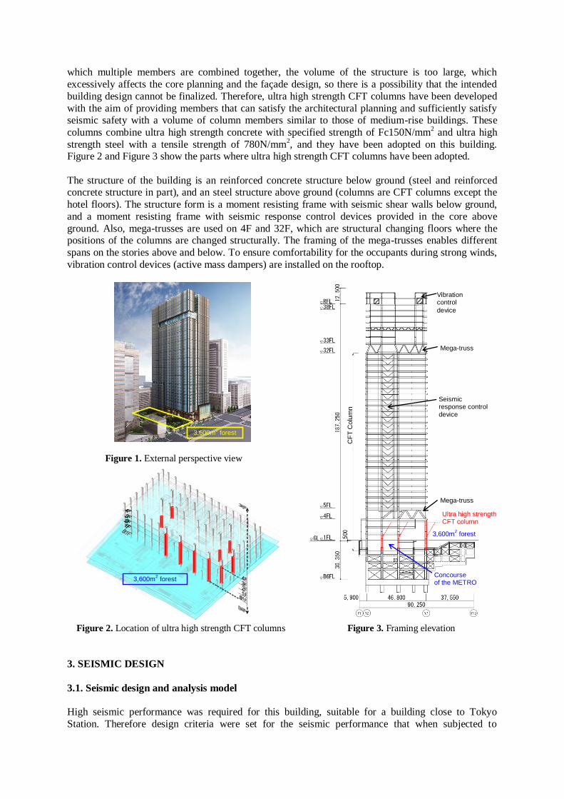
This building is an ultra high-rise building with 38 stories above ground (building height 199.7 m), 6 stories below ground (building depth 35.1 m), and three stories penthouse, with a total floor area of
about 198,000 m² (Fig. 1). Building uses are office, hotel, and stores, etc. One feature of the
architectural planning is that a large space is provided between 3,600 m² forest developed on
artificial ground at the first floor and the concourse of the Metro, so one task of the structural design was how to safely design the structural frame without causing major obstruction to this space.
Normally CFT columns are column members with excellent structural performance that utilize the characteristics of concrete, which is strong in compression, and steel, which are strong in bending
(tension), so they are adopted in high-rise buildings. However, when conventional materials are used,
the dimensions of the column cross-section are excessive on the lower stories when designing 200 to 300m class ultra high-rise buildings having long spans. Also when a mega structure is adopted in
which multiple members are combined together, the volume of the structure is too large, which
excessively affects the core planning and the façade design, so there is a possibility that the intended
building design cannot be finalized. Therefore, ultra high strength CFT columns have been developed
with the aim of providing members that can satisfy the architectural planning and sufficiently satisfy seismic safety with a volume of column members similar to those of medium-rise buildings. These
columns combine ultra high strength concrete with specified strength of Fc150N/mm2 and ultra high
strength steel with a tensile strength of 780N/mm2, and they have been adopted on this building.
Figure 2 and Figure 3 show the parts where ultra high strength CFT columns have been adopted.
The structure of the building is an reinforced concrete structure below ground (steel and reinforced concrete structure in part), and an steel structure above ground (columns are CFT columns except the
hotel floors). The structure form is a moment resisting frame with seismic shear walls below ground,
and a moment resisting frame with seismic response control devices provided in the core above
ground. Also, mega-trusses are used on 4F and 32F, which are structural changing floors where the positions of the columns are changed structurally. The framing of the mega-trusses enables different
spans on the stories above and below. To ensure comfortability for the occupants during strong winds,
vibration control devices (active mass dampers) are installed on the rooftop.
Figure 1. External perspective view
Figure 2. Location of ultra high strength CFT columns Figure 3. Framing elevation
3. SEISMIC DESIGN
3.1. Seismic design and analysis model
High seismic performance was required for this building, suitable for a building close to Tokyo
Station. Therefore design criteria were set for the seismic performance that when subjected to
3,600m2 forest
3,600m2 forest
3,600m2 forest
Vibration control
device
Concourse of the METRO
Ultra high strength CFT column
Seismic response control device
CF
T C
olu
mn
Mega-truss
Mega-truss
earthquakes that would occur extremely rarely (Level 2), the members will remain within the elastic
range, and the response story drift angle will not exceed 1/150. In addition, when subjected to
extremely large earthquakes (Level 3), 1.2 times the Level 2 earthquakes, the building will remain safe
(Table 1). As a result, the building will maintain very high seismic performance compared with an ordinary building. For this purpose, oil dampers as viscous dampers were provided in the core of the
building, and buckling restrained braces using low yield steel (LY225:yeild strength 255N/mm2) were
used in axial members as hysteretic dampers, each appropriately arranged so that seismic energy can be effectively absorbed.
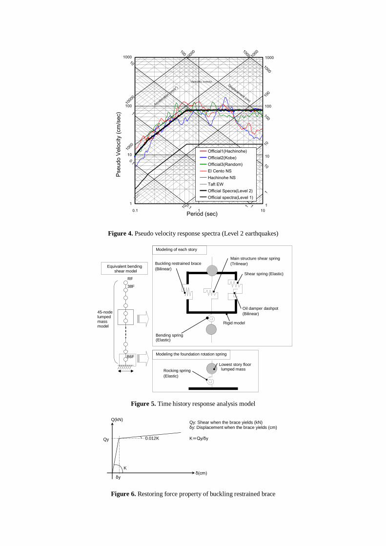
The 45-node lumped mass model including above ground and below ground as shown in Fig. 5 was used to confirm the performance using nonlinear time history response analysis, using several design
seismic motions as shown in Table 2 and Fig. 4. The nonlinear properties of the buckling restrained
braces were as shown in Fig. 6, and bilinear hysteretic rule was used. The oil dampers were set as
dampers with relief mechanism as shown in Fig. 7. As shown Fig. 8, the yield shear force of the buckling restrained braces in the transverse direction were set to about 20% of the Level 2 response
shear force, and the relief load of the oil dampers was set to about 10%. Also, the hysteretic restoring
force characteristics of the main frame were set as normal trilinear. Damping was internal viscous type damping proportional to the instantaneous stiffness, and the damping factor was 2% of the primary
natural frequency.
Also, nonlinear analysis with gradually increasing loads was carried out on a three-dimensional frame
model, to confirm the safety of the members under each level of earthquakes and to confirm the failure
mechanism. It was confirmed that with the design shear force coefficient (CB = 0.065), the stress in
each member was within the allowable stress, and when subjected to the shear force equivalent to Level 2 response (longitudinal direction CB = 0.150, transverse direction CB = 0.125), each member
was within the elastic limit.
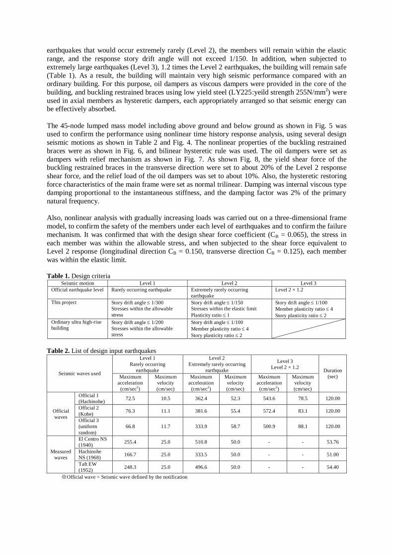
Table 1. Design criteria
Seismic motion Level 1 Level 2 Level 3
Official earthquake level Rarely occurring earthquake Extremely rarely occurring
earthquake
Level 2 × 1.2
This project Story drift angle 1/300
Stresses within the allowable
stress
Story drift angle 1/150
Stresses within the elastic limit
Plasticity ratio 1
Story drift angle 1/100
Member plasticity ratio 4
Story plasticity ratio 2
Ordinary ultra high-rise
building Story drift angle 1/200
Stresses within the allowable
stress
Story drift angle 1/100
Member plasticity ratio 4
Story plasticity ratio 2
Table 2. List of design input earthquakes
Seismic waves used
Level 1
Rarely occurring
earthquake
Level 2
Extremely rarely occurring
earthquake
Level 3
Level 2 × 1.2 Duration
(sec) Maximum
acceleration
(cm/sec2)
Maximum
velocity
(cm/sec)
Maximum
acceleration
(cm/sec2)
Maximum
velocity
(cm/sec)
Maximum
acceleration
(cm/sec2)
Maximum
velocity
(cm/sec)
Official
waves
Official 1
(Hachinohe) 72.5 10.5 362.4 52.3 543.6 78.5 120.00
Official 2
(Kobe) 76.3 11.1 381.6 55.4 572.4 83.1 120.00
Official 3
(uniform
random)
66.8 11.7 333.9 58.7 500.9 88.1 120.00
Measured
waves
El Centro NS
(1940) 255.4 25.0 510.8 50.0 - - 53.76
Hachinohe
NS (1968) 166.7 25.0 333.5 50.0 - - 51.00
Taft EW
(1952) 248.3 25.0 496.6 50.0 - - 54.40
※Official wave = Seismic wave defined by the notification
Accele
ratio
n (cm
/s2 )
10 1
Displacement (cm
)
1000
0
1000
0
1000
1000
100
100
10
1
1000
1000
100
100
10
10
1
1
0.1
0.1
1
10
100
1000
0.1 1 10Period (sec)
Pseudo V
elo
city (
cm
/sec)
Official1(Hachinohe)
Official2(Kobe)
Official3(Random)
El Cento NS
Hachinohe NS
Taft EW
Official Specra(Level 2)
Official spectra(Level 1)
Velocity (cm/s)
1000
100
10
1
Figure 4. Pseudo velocity response spectra (Level 2 earthquakes)
B6F
Equivalent bending shear model
45-node lumped mass model
Modeling of each story
Rigid model
Bending spring (Elastic)
Main structure shear spring
(Trilinear)
RF
38F
Buckling restrained brace
(Bilinear)
制震ブレースのせん断バネ
(バイリニア型)
(せん断変形成分のみ考慮)
Oil damper dashpot
(Bilinear)
Shear spring (Elastic)
Rocking spring
(Elastic)
Modeling the foundation rotation spring
Lowest story floor lumped mass
Figure 5. Time history response analysis model
0.012K
F2
K δ(cm)
Q(kN)
δy
Qy
Qy: Shear when the brace yields (kN) δy: Displacement when the brace yields (cm)
K=Qy/δy
Figure 6. Restoring force property of buckling restrained brace

V(cm/sec)
F(kN)
V1 = 1.6 cm/sec
V2 = 30cm/sec
F1 = 1600kN
F1: Damping force at point of bend (kN) F2: Maximum damping force (kN) V1: Velocity at point of bend (cm/sec) V2: Maximum velocity (cm/sec)
C1=F1/V1
C1
F2 = 2000kN
Figure 7. Restoring force property of oil damper
123456789
101112131415161718192021222324252627282930313233343536373839
0 50000 100000 150000 200000
Sto
ry
Story shear force (kN)
Buckling
restrained
brace
Level 2 response
shear force
(CB=0.125)
Oil damper
Figure 8. Ratio of shear strength of seismic response control system (in the transverse direction)
3.2. Time history response analysis
From the results of eigen-value analysis it was found that the primary natural period T = 4.378 seconds,
and that the building is slightly stiff compared with buildings on a similar scale because the structure
was required to satisfy high design criteria.
123456789
101112131415161718192021222324252627282930313233343536373839
0.000 0.002 0.004 0.006 0.008 0.010 0.012
Maximum response story drift angle (rad)
Sto
ry
Official1(Hachinohe)
Official2(Kobe)
Official3(Random)
El-Centro NS
Hachinohe NS
Taft EW
1/300 1/200
123456789
101112131415161718192021222324252627282930313233343536373839
0.000 0.002 0.004 0.006 0.008 0.010 0.012
Maximum respose story drift angle (rad)
Sto
ry
1/150 1/100
123456789
101112131415161718192021222324252627282930313233343536373839
0.000 0.002 0.004 0.006 0.008 0.010 0.012
Maximum response story drift angle (rad)
Sto
ry
1/100
Maximum
Value:1/376
Maximum
Value:1/171Maximum
Value:1/136
(a) Level 1 earthquakes (b) Level 2 earthquakes (c) Level 3 earthquakes
Figure 9. Time history response analysis results (in the transverse direction)

Figure 9 shows the results for the maximum response story drift angle in the transverse direction. In all
cases, the design criteria are satisfied, so it can be seen that the seismic response control system used
in this building reduces the amplification of the response of the stories above ground due to the
earthquakes. Also, under the Level 2 earthquakes all members are within the elastic range, and under the Level 3 earthquakes some beams become plastic, with maximum story plasticity ratio of 1.264.
4. ULTRA HIGH STRENGTH CFT COLUMNS
4.1. Use of ultra high strength CFT columns in the building
A total of ten ultra high strength CFT columns that combined 780N/mm
2 steel and Fc150N/mm
2
concrete were used in the building: six columns on the south face of the building spanning 14.4 m
from the basement second story to the third story above ground, and four corner columns on 1F in the center of the building supporting 22-m floors above ground in both north and south directions. Figure
10 shows the comparison of the axial load resistance of CFT columns using standard materials
(normal strength), high strength materials, and using the combination of the ultra high strength
materials. The maximum axial load of the ultra high strength CFT column is 2.3 times that of the ordinary strength CFT column, so it has an extremely high axial load bearing capacity. As a result,
columns that are arranged at 7.2 m spans in beam directions in the ultra high-rise building can be
concentrated at 14.4 m, so it is possible to provide the large atrium space in the lower story portion of
Figure 10. Comparison of axial load resistance of CFT columns
Figure 11. Details of ultra high strength CFT column
the ultra high-rise building. Also, as large cross-section CFT columns -1500×1500×50, the elastic
deformation capacity is ensured by using reduced maximum axial load ratios compared with normal, such as maximum axial load ratio under long-term loads 0.13, and maximum axial load ratio during
Level 3 earthquake 0.21. Fig. 11 shows the details of the beam to column connection of the CFT
column. The concrete pouring hole (700mm) in the diaphragm has an opening area of about 20% of the column concrete cross-sectional area, for improved filling of concrete. Also, the haunches of the
beams are to ensure that in a major earthquake the plastic zone of the beams go from the end of the beam towards the center of the beam.
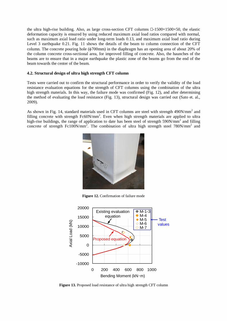
4.2. Structural design of ultra high strength CFT column
Tests were carried out to confirm the structural performance in order to verify the validity of the load
resistance evaluation equations for the strength of CFT columns using the combination of the ultra high strength materials. In this way, the failure mode was confirmed (Fig. 12), and after determining
the method of evaluating the load resistance (Fig. 13), structural design was carried out (Sato et. al.,
2009).
As shown in Fig. 14, standard materials used in CFT columns are steel with strength 490N/mm
2 and
filling concrete with strength Fc60N/mm2. Even when high strength materials are applied to ultra
high-rise buildings, the range of application to date has been steel of strength 590N/mm2 and filling
concrete of strength Fc100N/mm2. The combination of ultra high strength steel 780N/mm
2 and
Figure 12. Confirmation of failure mode
-10000
-5000
0
5000
10000
15000
20000
0 200 400 600 800 1000
曲げ耐力(kN・m)
軸力
( kN)
M-1-3M-4M-5M-6M-7
既往評価式
提案式
Figure 13. Proposed load resistance of ultra high strength CFT column
Axia
l L
oad
(kN
)
Bending Moment (kN・m)
Existing evaluation equation
Proposed equation
Test values
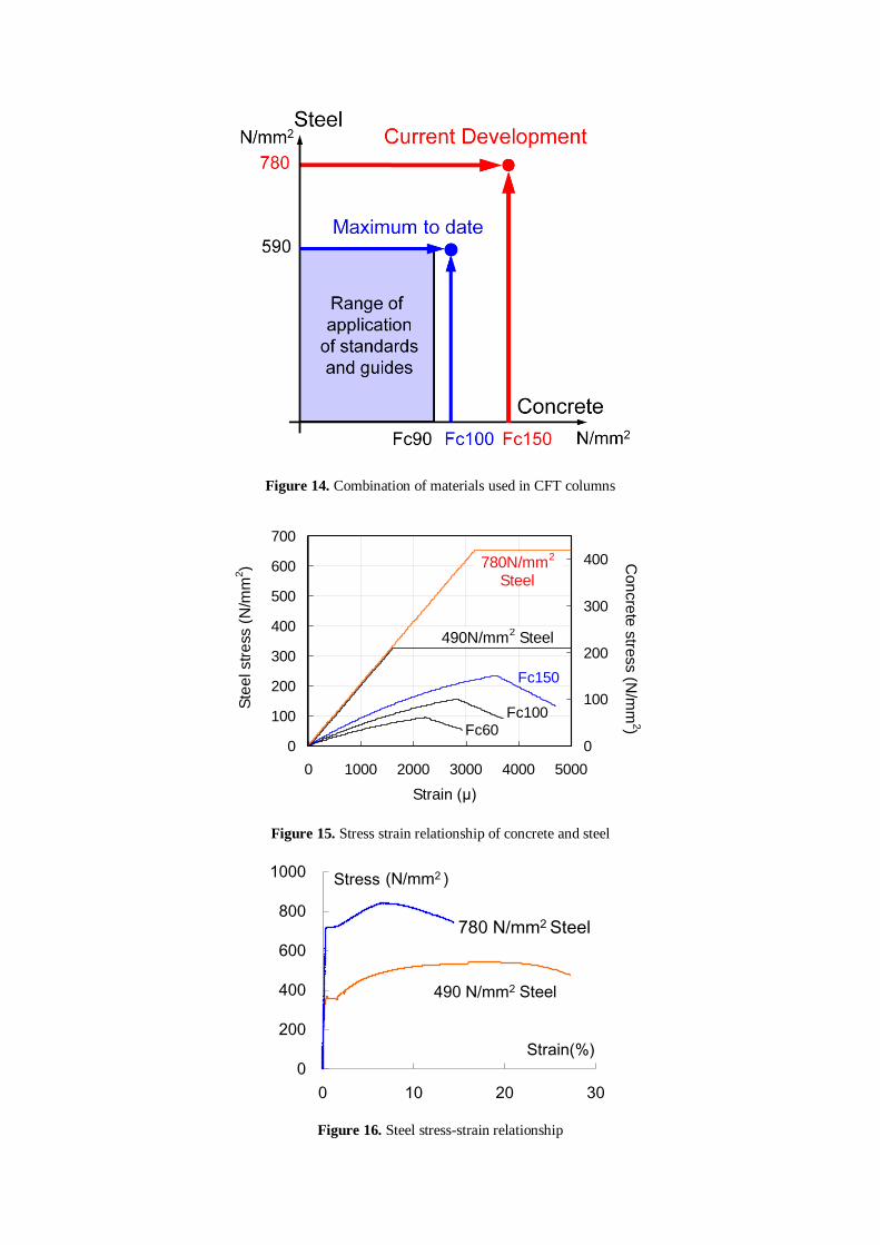
Figure 14. Combination of materials used in CFT columns
0
100
200
300
400
500
600
700
0 1000 2000 3000 4000 5000
ひずみ(μ)
鋼材応力(N
/mm
2)
0
100
200
300
400
コンクリート応力(N
/mm
2)
Fc150
780N/mm2鋼
490N/mm2鋼
Fc100Fc60
Figure 15. Stress strain relationship of concrete and steel
0
200
400
600
800
1000
0 10 20 30
Stress
Strain(%)
(N/mm2 )
780 N/mm2 Steel
490 N/mm2 Steel
Figure 16. Steel stress-strain relationship
Ste
el str
ess (
N/m
m2)
Strain (μ)
Con
cre
te s
tress (N
/mm
2)
780N/mm2
Steel
490N/mm2 Steel
ultra high strength concrete Fc150N/mm2 used in this building is the world's highest class strength of
CFT column. Figure 15 shows the stress-strain relationship for the steel and concrete. The limiting
strain of the 780N/mm2 steel and the Fc150N/mm
2 concrete are virtually the same, so this is a
combination that can exhibit the advantages of high strength materials to the maximum extent. The stress-strain relationship of the 780N/mm
2 ultra high strength steel is shown in Fig. 16. Although the
strength is about 1.6 times greater than conventional steel, the ratio of the yeild strength to the tensile
strength is high, and the strain at the tensile strength is small. Therefore in the design of this column, enough margin to remain within the elastic range is required.
4.3. Constructability of ultra high strength materials
Steel with strength 780N/mm2 has obtained the approval of the minister as construction material, it can
be produced, and its performance has been verified in structural tests. Also, stable quality
(constructability and strength) can be ensured for ultra high strength concrete Fc150N/mm2 as a result
of the development of high performance super-plasticizer, and there is experience with application in
reinforced concrete (RC) columns in the lower stories of ultra high-rise residential buildings. There is
much construction experience in the use of this concrete in RC columns, but there have been very few studies done on its application to CFT columns. To actually apply these high strength materials to CFT
columns, following issues regarding construction and production aspects had to be addressed.
- Fc150N/mm
2 class ultra high strength concrete contains much binder material in the ingredients,
mainly cement, so when the concrete is fresh, viscosity is high. Therefore pump delivery
technology that is capable of supplying concrete stably with high pressure is necessary in order to
reliably pour the concrete into the steel tubes.
- In order to fill steel tubes with Fc150N/mm2 class ultra high strength concrete, blending
technology that minimizes shrinkage when the concrete has hardened is necessary.
- In order to use high strength steel materials, it is necessary to select the welding materials and the
various conditions (location of welding works, temperature, weld location, welding equipment,
welding method) in accordance with special welding control methods.
In response to these issues, data concerning these high strength materials was accumulated by carrying
out many material tests and construction tests, up to the level where construction can be carried out (Narihara et. al., 2009), (Goto et. al., 2009).
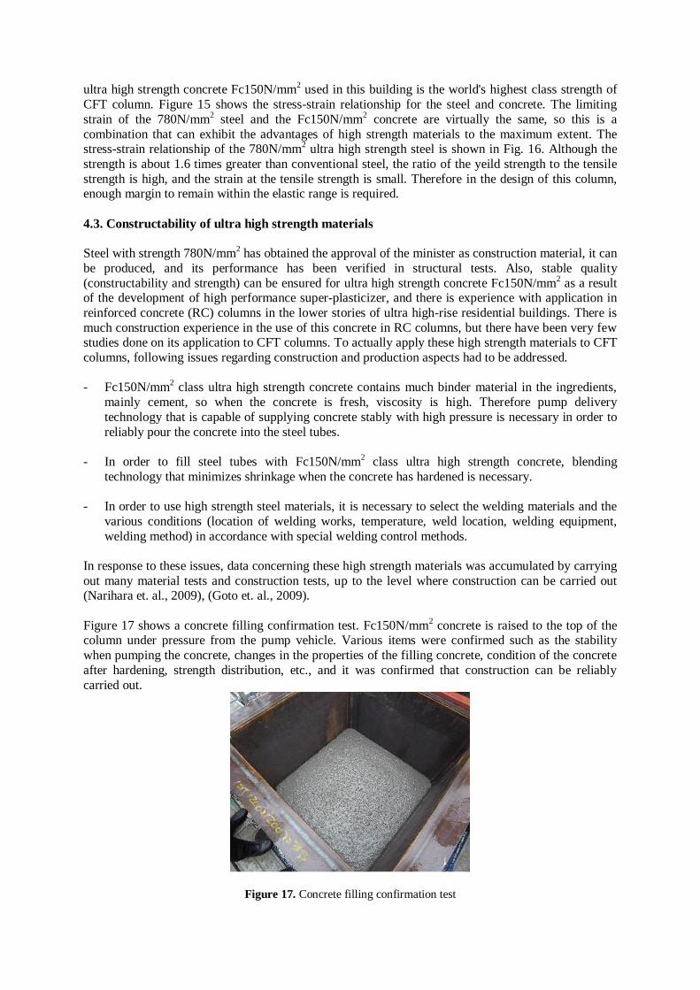
Figure 17 shows a concrete filling confirmation test. Fc150N/mm2 concrete is raised to the top of the
column under pressure from the pump vehicle. Various items were confirmed such as the stability
when pumping the concrete, changes in the properties of the filling concrete, condition of the concrete
after hardening, strength distribution, etc., and it was confirmed that construction can be reliably
carried out.
Figure 17. Concrete filling confirmation test

Figure 18. Factory weld construction test piece Figure 19. Site weld construction test piece
Figure 18 is a full-sized test piece in a factory welding construction test. The corner welds and the
diaphragm welds of the column were carried out by fabricating a box column at the factory. Also, Figure 19 shows a test piece for a site welding construction test that was carried out. The welding was
carried out in the horizontal attitude at the actual site. The results of these tests confirmed the
combination of steel material and weld material, the weld performance, and weld constructability.
5. CONCUSION
This paper has reported the outline of the structural design of an ultra high-rise building using ultra
high strength CFT columns that combine ultra high strength steel 780N/mm2 and ultra high strength
concrete Fc150N/mm2. By combining with response control systems, these members have elastic
deformation capability suitable for satisfying high design criteria. In addition these members can
achieve structural framing and architectural spaces with a high degree of freedom as a result of their
large load bearing capacity, so it is considered that in the future their application to ultra high rise buildings will expand.
REFERENCES
Sato, E., Matsumoto, S., Narihara, H., Komuro, T. and Yasuda, S. (2009). Structural Performance of CFT
Column Using Super High Strength Materials (Part1-2). Summaries of Technical Papers of Annual
Meeting, Architectural Institute of Japan, Structure Ⅲ, pp.1217-1220. (in Japanese)
Morita, K., Keii, M. and Matsumoto, S. (2011). Applications of high performance structural steels to high-rise
steel buildings. The 6th International Symposium on STEEL STRUCTURE (ISSS-2011), International Journal of Steel Structure, pp.21-35.
Narihara, H., Kobayashi, M., Matsumoto, S., Inaba, Y., Goto, K. and Fujisawa, S. (2010). Welding Procedure
Test on Build up Box Column Made of 780N/mm2 Class Tensile Strength Steel for Building Structure
(Part1-2). Summaries of Technical Papers of Annual Meeting, Architectural Institute of Japan, Material
and Construction, pp.1123-1126. (in Japanese)
Goto, K., Kuroiwa, S., Matsumoto, S., Kawamoto, S., Tsujiya, K., Nakamura, T. and Yagi, K. (2011).
Experimental Study on Construction with CFT Column using Fc150N/mm2 Concrete by Actual Size
Models. Summaries of Technical Papers of Annual Meeting, Architectural Institute of Japan, Material and
Construction, pp.333-334. (in Japanese)