Embed Size (px)
Citation preview
NREL is a national laboratory of the U.S. Department of Energy Office of Energy Efficiency and Renewable Energy operated by the Alliance for Sustainable Energy, LLC
Marine and Hydrokinetic Device Modeling Workshop
NREL
March 1, 2011
STRUCTURAL DESIGN OF THE TIDAL CURRENT TURBINE COMPOSITE BLADE
Schematic of the Tidal Current Turbine
2National Renewable Energy Laboratory Innovation for Our Energy Future
We focus only on the blade, the key energy extractor.Follow a decoupled design approach.
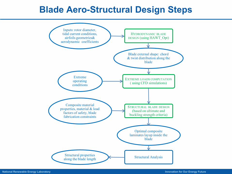
Blade Aero-Structural Design Steps
3National Renewable Energy Laboratory Innovation for Our Energy Future
HYDRODYNAMIC BLADEDESIGN (using HAWT_Opt)
EXTREME LOADS COMPUTATION( using CFD simulations)
STRUCTURAL BLADE DESIGN(based on ultimate and
buckling strength criteria)
Inputs: rotor diameter, tidal current conditions,
airfoils geometries& aerodynamic coefficients
Composite material properties, material & load
factors of safety, blade fabrication constraints
Extreme operating conditions
Blade external shape: chord & twist distribution along the
blade
Optimal composite laminates layup inside the
blade
Structural properties along the blade length Structural Analysis
Step 1: Hydrodynamic Design
4National Renewable Energy Laboratory Innovation for Our Energy Future
Objective: Get blade external shapeChord distribution along the blade Twist distributionAirfoil shape distribution
(Currently, not designed.NACA 631-424 used from 20% blade span location to the blade tip.Circular root section that transitions to NACA 631-424.)
HAWT_Opt used for hydrodynamic design.
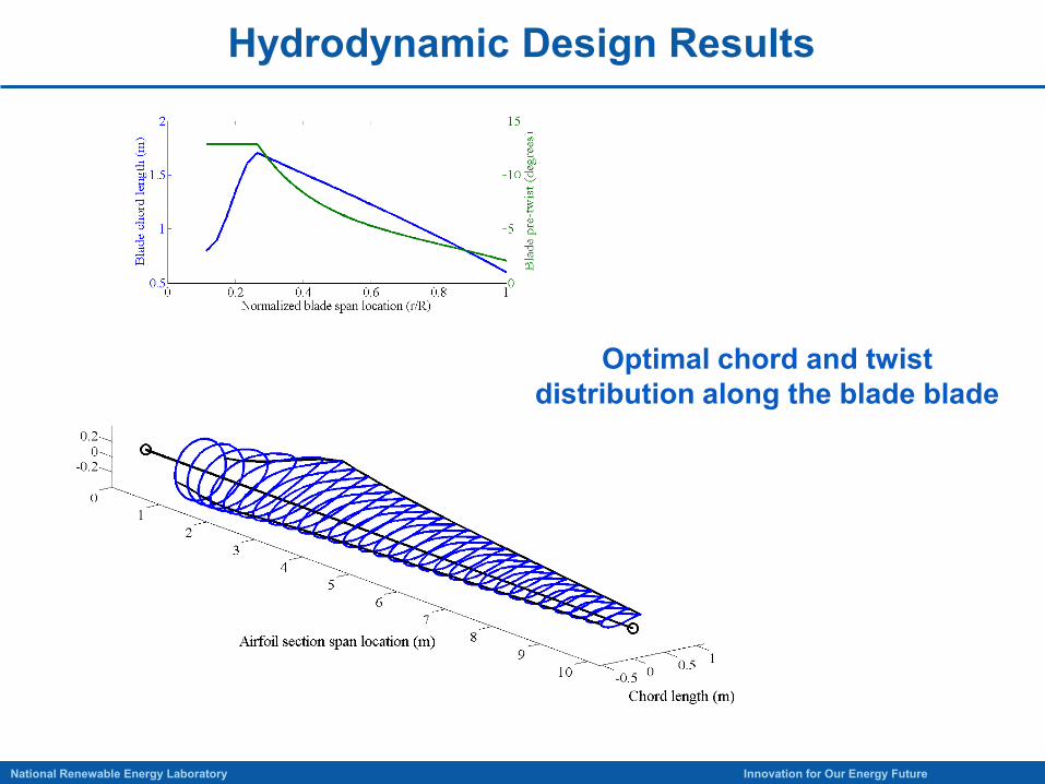
Hydrodynamic Design Results
5National Renewable Energy Laboratory Innovation for Our Energy Future
Optimal chord and twist distribution along the blade blade
Step 2: Extreme Loads Computation
6National Renewable Energy Laboratory Innovation for Our Energy Future
Define extreme operating conditionsEOC1: Tidal current is 6 m/s velocity, twice
the measured maximum velocity. Blades fully feathered and shaft brake engaged to prevent rotor rotation. EOC2: Turbine operates normally at the peak
thrust and peak blade root flap moment operating condition (corresponds to 1.9 m/s tidal current speed, zero degree blade pitch angle, 11.5 rotor rpm). Experiences a sudden tidal gust that boosts the tidal current velocity to 2.85 m/s, 1.5 times the normal current velocity.
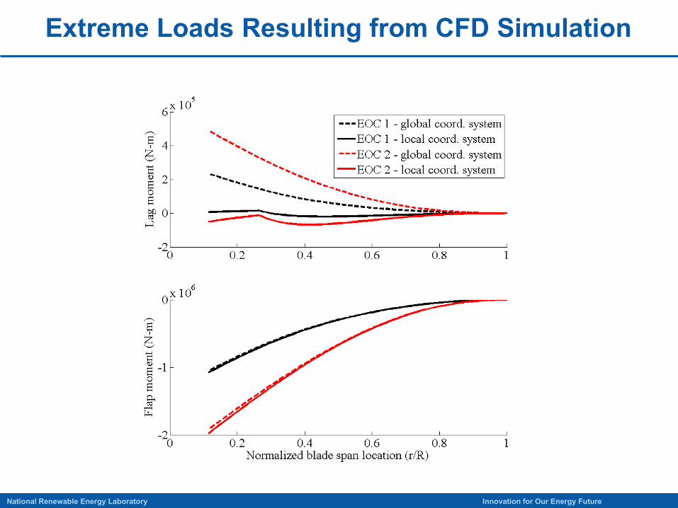
Extreme Loads Resulting from CFD Simulation
7National Renewable Energy Laboratory Innovation for Our Energy Future
Step 3: Blade Structural Design
8National Renewable Energy Laboratory Innovation for Our Energy Future
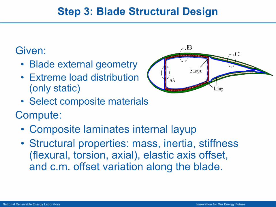
Given:• Blade external geometry• Extreme load distribution
(only static)• Select composite materials
Compute:• Composite laminates internal layup• Structural properties: mass, inertia, stiffness
(flexural, torsion, axial), elastic axis offset, and c.m. offset variation along the blade.
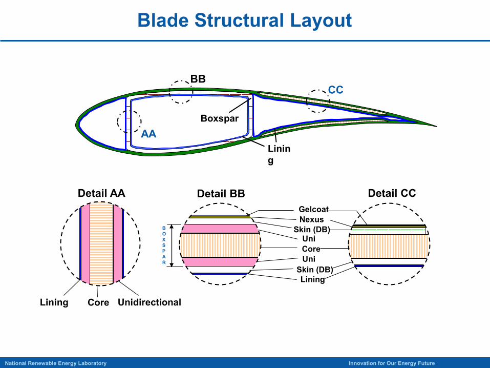
Blade Structural Layout
9National Renewable Energy Laboratory Innovation for Our Energy Future
Core
Nexus
Uni
Gelcoat
Lining
Uni
Lining UnidirectionalCore
BBCC
AABoxspar
Lining
BOXSPAR
Detail BBDetail AA Detail CC
Skin (DB)
Skin (DB)
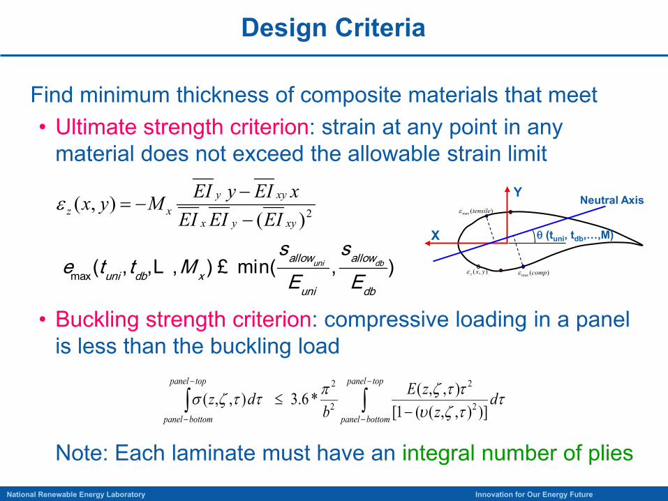
Design Criteria
10National Renewable Energy Laboratory Innovation for Our Energy Future
Find minimum thickness of composite materials that meet• Ultimate strength criterion: strain at any point in any
material does not exceed the allowable strain limit
• Buckling strength criterion: compressive loading in a panel is less than the buckling load
Note: Each laminate must have an integral number of plies
2)(),(
xyyx
xyyxz EIEIEI
xEIyEIMyx−−
−=ε
max( , , , ) min( , )uni dballow allowuni db x
uni db
t t ME E
s se £L
ττζυττζπττζσ d
zzE
bdz
toppanel
bottompanel
toppanel
bottompanel∫∫
−
−
−
− −≤
)]),,((1[),,(*6.3),,( 2
2
2
2
Y
X
Neutral Axis
θ (tuni, tdb,…,M)
)(max compε
)(max tensileε
),( yxzε
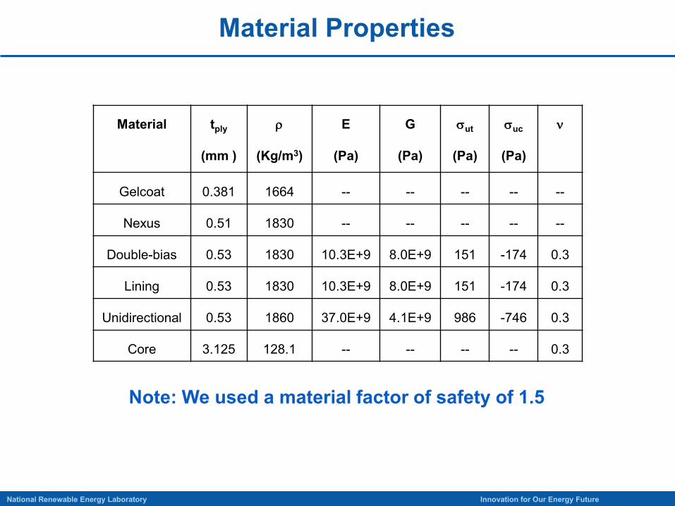
Material Properties
11National Renewable Energy Laboratory Innovation for Our Energy Future
Material tply
(mm )
ρ
(Kg/m3)
E
(Pa)
G
(Pa)
σut
(Pa)
σuc
(Pa)
ν
Gelcoat 0.381 1664 -- -- -- -- --
Nexus 0.51 1830 -- -- -- -- --
Double-bias 0.53 1830 10.3E+9 8.0E+9 151 -174 0.3
Lining 0.53 1830 10.3E+9 8.0E+9 151 -174 0.3
Unidirectional 0.53 1860 37.0E+9 4.1E+9 986 -746 0.3
Core 3.125 128.1 -- -- -- -- 0.3
Note: We used a material factor of safety of 1.5
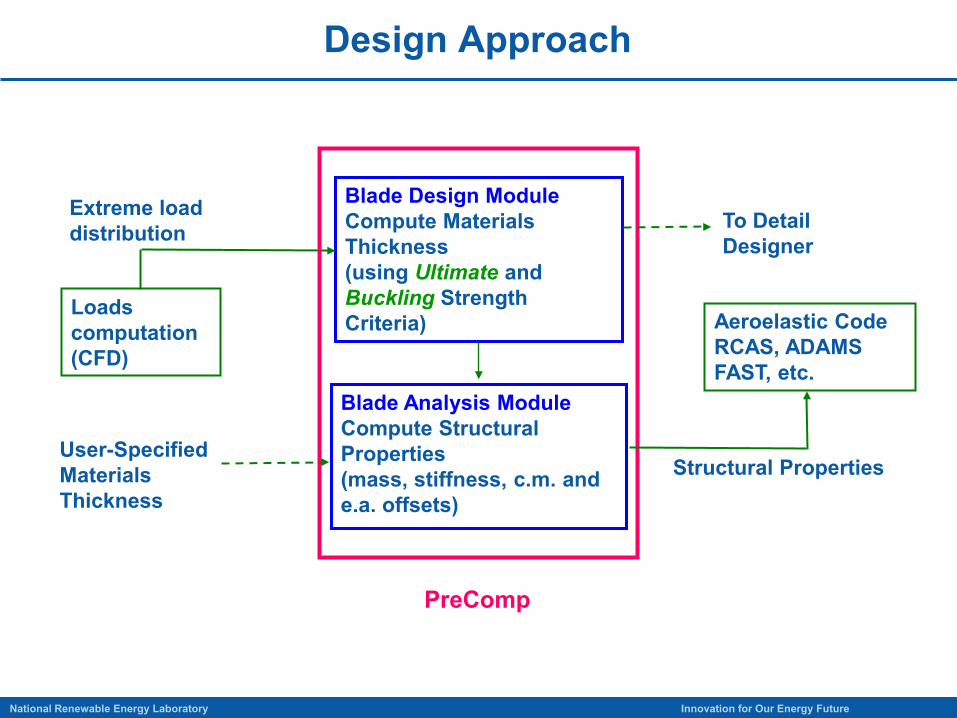
Design Approach
12National Renewable Energy Laboratory Innovation for Our Energy Future
Loads computation(CFD)
Blade Design ModuleCompute Materials Thickness(using Ultimate and Buckling Strength Criteria) Aeroelastic Code
RCAS, ADAMSFAST, etc.
Blade Analysis ModuleCompute Structural Properties(mass, stiffness, c.m. and e.a. offsets)
Extreme load distribution
PreComp
Structural PropertiesUser-Specified Materials Thickness
To Detail Designer
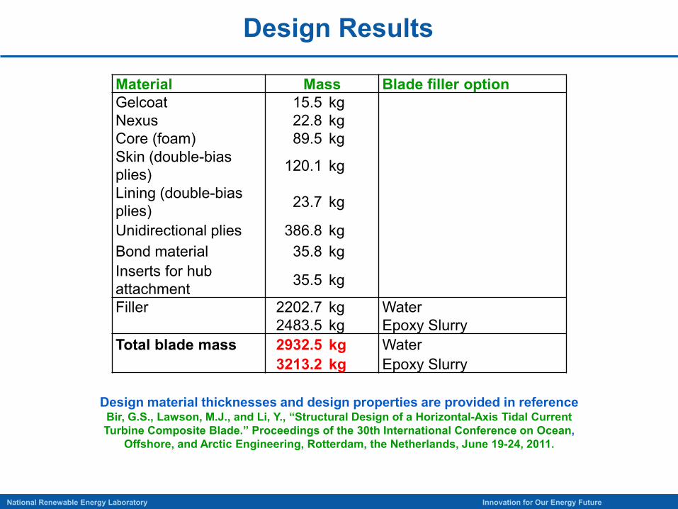
Design Results
13National Renewable Energy Laboratory Innovation for Our Energy Future
Material Mass Blade filler optionGelcoat 15.5 kgNexus 22.8 kgCore (foam) 89.5 kgSkin (double-bias plies) 120.1 kg
Lining (double-bias plies) 23.7 kg
Unidirectional plies 386.8 kgBond material 35.8 kgInserts for hub attachment 35.5 kg
Filler 2202.7 kg Water2483.5 kg Epoxy Slurry
Total blade mass 2932.5 kg Water3213.2 kg Epoxy Slurry
Design material thicknesses and design properties are provided in referenceBir, G.S., Lawson, M.J., and Li, Y., “Structural Design of a Horizontal-Axis Tidal Current Turbine Composite Blade.” Proceedings of the 30th International Conference on Ocean,
Offshore, and Arctic Engineering, Rotterdam, the Netherlands, June 19-24, 2011.
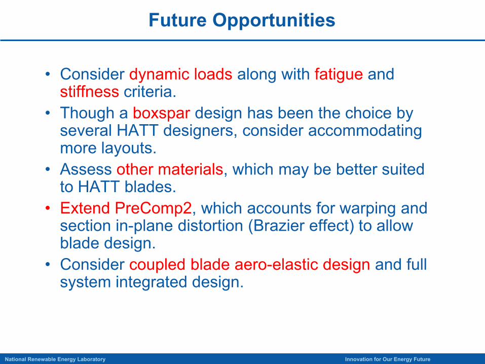
Future Opportunities
14National Renewable Energy Laboratory Innovation for Our Energy Future
• Consider dynamic loads along with fatigue and stiffness criteria.
• Though a boxspar design has been the choice by several HATT designers, consider accommodating more layouts.
• Assess other materials, which may be better suited to HATT blades.
• Extend PreComp2, which accounts for warping and section in-plane distortion (Brazier effect) to allow blade design.
• Consider coupled blade aero-elastic design and full system integrated design.
NREL is a national laboratory of the U.S. Department of Energy Office of Energy Efficiency and Renewable Energy operated by the Alliance for Sustainable Energy, LLC
Gunjit BirNational Wind Technology Center
Contact Information:Phone: 303-384-6953Email: [email protected]
Questions?