Embed Size (px)
Citation preview
C H A P T E R
1Structural Design
Process
ch01_4643 2/5/07 12:14 PM Page 1
COPYRIG
HTED M
ATERIAL
1.1 Nature of the Process
This book is primarily intended as a textbook for studentsenrolled in professionally accredited architecture pro-grams. A secondary audience includes interns preparingfor the architectural registration exams. There may also belimited markets for professional architects, structural en-gineers desiring to better understand the architect’s ap-proach to structures in the context of the larger designproblem, and persons interested in pursuing a career in ei-ther architecture or structural engineering.
Architects have a huge array of issues to address inarchitectural practice. Among these are the following:keeping rain out of a building, getting water off a site,thermal comfort, visual comfort, space planning, fireegress, fire resistance, corrosion and rot resistance, ver-min resistance, marketing, client relations, the law,contracts, construction administration, the functional pur-poses of architecture, the role of the building in the largercultural context, security, economy, resource manage-ment, codes and standards, and how to make a buildingwithstand all the forces to which it will likely be subjectedduring its lifetime. This last subject area is referred to asarchitectural structures.
Because of the extraordinary range of demands on anarchitect’s time and skills and the extraordinary numberof subjects that architecture students must master, archi-tectural structures are typically addressed in only two orthree lecture courses in an accredited architectural cur-riculum in the United States. These two or three lecturecourses must be contrasted with the ten or twelve coursesthat will normally be taken by a graduate of an accred-ited structural engineering curriculum. This contrast inlevel of focus makes it clear why a good structural engi-neering consultant is a very valuable asset to an architect.However, having a good structural consultant does notrelieve the architect of serious responsibility in the struc-tural domain. All architects must be well versed in mat-ters related to structures. The architect has the primaryresponsibility for establishing the structural concept for abuilding, as part of the overall design concept, and mustbe able to speak the language of the structural consultantwith sufficient skill and understanding to take full ad-vantage of the consultant’s capabilities.
Most books on structures are written by structural en-gineers for an audience of structural engineers. This focusis not appropriate in nature to the needs of the architect,who must understand how structure fits into the larger de-sign context. Furthermore, it is not appropriate in scale,inasmuch as the texts required by an engineering studentover the course of that student’s education will fill anentire cabinet. Given the wide range of other learningresponsibilities of an architecture student, there is notenough money to acquire, or time to use, an entire cab-
inet full of books on structures. To support the learningneeds of architecture students, a text is needed that is dif-ferent in both scope and approach from the reference ma-terial provided for engineers.
It is the goal of this text to supply the architecture stu-dent with a comprehensive set of learning and referencematerials to help prepare that student to enter the work-force as a serious professional, competent to deal withstructural issues at the level, and in the manner, appro-priate to architects. This book can also serve as a valu-able reference for architectural interns preparing for thearchitectural registration examinations.
1.2 General Comments RegardingArchitectural Education
Structural design is one of the more rigorous aspects ofarchitectural design. Much knowledge has been gener-ated and codified over the centuries that human beingshave been practicing in and developing this field. Thisbook gives primary attention to those things that areknown, quantified, and codified.
However, very few things in the realm of architectureyield a single solution. To any given design problem,there are many possible solutions, and picking the bestsolution is often the subject of intense debate. Therefore,no one should come to this subject matter assuming thatthis text, or any text, is going to serve up a single, opti-mized solution to any design problem, unless that designproblem has been so narrowly defined as to be artificial.
In design, there is always a great deal of latitude for per-sonal expression. Design is purposeful action. The designermust have an attitude to act. Architecture students developan attitude through a chaotic learning process involving alot of trial and error. In going through this process, an ar-chitecture student must remain aware of a fundamentalpremise: the process is more important than the product;that is, the student’s learning and development are moreimportant than the output. The student has a license tomake mistakes. It is actually more efficient to plow forwardand make mistakes than to spend too much time trying tofigure out how to do it perfectly the first time. To para-phrase the immortal words of Thomas Edison: To havegood ideas, you should have many ideas and then throwout the bad ones. Of course, throwing out the bad ones re-quires a lot of rigorous and critical thinking. No one shouldever fall in love with any idea that has not been subjectedto intense and prolonged critical evaluation and withstoodthe test with flying colors. Furthermore, important ideasshould be subjected to periodic reevaluation. Times andconditions change. Ideas that once seemed unassailablemay outlive their usefulness or, at the very least, need up-dating in the light of new knowledge and insights.
2 STRUCTURAL DESIGN PROCESS
ch01_4643 2/5/07 12:14 PM Page 2
Structural Design
Predominantly the domainof the Architect
Structural Analysis
Predominantly the domainof the Engineer
Typical questions:What should the form be?
What are the structural elements?How do the elements fit and work together?
Characterizations:Artistic
“Feelable”Emphasizes “soul”
IntuitiveLearnableChaotic
Trial-and-error learning processIdiosyncratic and individualistic
Typical questions:How big do the structural elements need to be?
What grade of material do we use?How strong do the connectors need to be?
Characterizations:ScientificKnowable
Emphasizes “efficiency”Analytic
TeachableOrderly
SystematizedGeneralized and codified
This text focuses primarily on exploring the known,quantified, and codified, but it also honors the chaoticlearning process described here. On some projects, stu-dents will be given fairly wide latitude to generateconcepts and to explore. Optimally, the educational ex-perience will be stronger if the student explores this sub-ject matter in the context of a design process, such aswould occur in a studio environment, where feedback isprovided by enlightened people with a wide range of ex-perience and philosophical points of view.
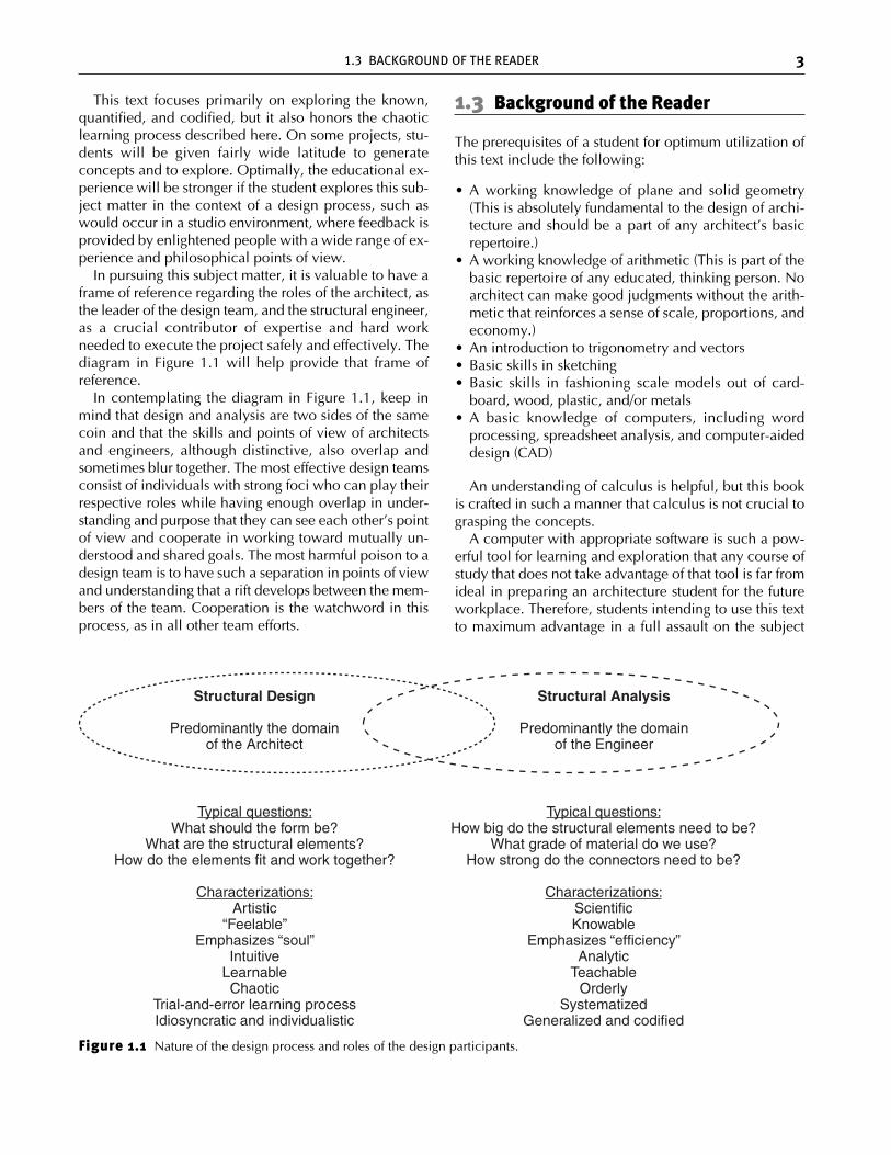
In pursuing this subject matter, it is valuable to have aframe of reference regarding the roles of the architect, asthe leader of the design team, and the structural engineer,as a crucial contributor of expertise and hard workneeded to execute the project safely and effectively. Thediagram in Figure 1.1 will help provide that frame ofreference.
In contemplating the diagram in Figure 1.1, keep inmind that design and analysis are two sides of the samecoin and that the skills and points of view of architectsand engineers, although distinctive, also overlap andsometimes blur together. The most effective design teamsconsist of individuals with strong foci who can play theirrespective roles while having enough overlap in under-standing and purpose that they can see each other’s pointof view and cooperate in working toward mutually un-derstood and shared goals. The most harmful poison to adesign team is to have such a separation in points of viewand understanding that a rift develops between the mem-bers of the team. Cooperation is the watchword in thisprocess, as in all other team efforts.
1.3 Background of the Reader
The prerequisites of a student for optimum utilization ofthis text include the following:
• A working knowledge of plane and solid geometry(This is absolutely fundamental to the design of archi-tecture and should be a part of any architect’s basicrepertoire.)
• A working knowledge of arithmetic (This is part of thebasic repertoire of any educated, thinking person. Noarchitect can make good judgments without the arith-metic that reinforces a sense of scale, proportions, andeconomy.)
• An introduction to trigonometry and vectors• Basic skills in sketching• Basic skills in fashioning scale models out of card-
board, wood, plastic, and/or metals• A basic knowledge of computers, including word
processing, spreadsheet analysis, and computer-aideddesign (CAD)
An understanding of calculus is helpful, but this bookis crafted in such a manner that calculus is not crucial tograsping the concepts.
A computer with appropriate software is such a pow-erful tool for learning and exploration that any course ofstudy that does not take advantage of that tool is far fromideal in preparing an architecture student for the futureworkplace. Therefore, students intending to use this textto maximum advantage in a full assault on the subject
1.3 BACKGROUND OF THE READER 3
Figure 1.1 Nature of the design process and roles of the design participants.
ch01_4643 2/5/07 12:14 PM Page 3
should have access to a computer with word processing,a spreadsheet program, and a structural analysis program.Examples of the latter are Multiframe, Strudl, SAP, RISA,STAAD.Pro, Tekla Xsteel, S-Frame, ETABS, MIDAS,ProSteel 3D, and RamSteel. This book will provide ex-amples of the principles of analysis on which these pro-grams are based. It will also take the student throughmany of these examples in the form of assignmentsdesigned to reinforce the concepts.
The computer analysis programs are important forseveral reasons:
1. They eliminate much of the tedious math, allowingthe student to focus on concepts and to explore thebehavior and attributes of many more structuralforms than would be possible if the student werestraddled with the responsibility of carrying out all ofthe math longhand.
2. The computer facilitates the analysis of very complexthree-dimensional structures that simply could not bedone reliably by longhand analysis.
3. The programs provide visualization tools that are in-valuable for exploring both geometry and structuralbehavior.
1.4 Vehicles for Delivering the Concepts
1. Freebody diagrams. These are at the absolute heartof structural design. Understanding how freebodiesare constructed and interpreted is vital to the mostbasic concepts in structures.
2. Math (primarily geometry and arithmetic). These givescale and rigor to everything the architect does instructural design.
3. Spreadsheet programs for computers. These pro-grams are powerful aids in organizing and carryingout computations. They provide:• Sophisticated and rapid computational tools• Ease of use• A record of the inputs that can be used in check-
ing and troubleshooting• A record of the equations that can be used in
checking and troubleshooting• Graphic output for visualization and presentations
These programs are already commonplace tools forarchitects to use in generating budgets and doingvalue analysis. Applying them in a structures courseto generate computational templates is an obviousmatch.
4. Computer simulations showing axial forces, axialstresses, moments, bending stresses, shear forces,shear stresses, and deformation under various load-ing conditions. These programs are a requirement inany serious course in structures. The ease they pro-
vide in visualizing and exploring structural behavioris simply unprecedented. The use of these programsis featured heavily in the examples and assignmentsin this book.
5. Physical testing and physical models demonstratingthe structural behavior of elements and/or systems ofelements. The tactile feedback provided by physicalexperiments and models is a powerful aid to a stu-dent’s comprehension. They are not easy to make ina manner that truly simulates the behavior of a full-sized structure, but they are worth the effort. Somephenomena, such as buckling, are better understoodin physical models than in any other learning media.Moreover, models teach students about statisticalvariations in performance that are not apparent inpurely computational processes. There is nothing liketesting a series of models that were intended to beidentical to help students understand why safety fac-tors are important.
6. Design solutions embodied in actual building struc-tures. There are vast insights to be gathered from thesuccessful designs born of great minds that havegrappled with this subject over the centuries. Theseshould be revisited often, each time with a fresh eyeto see things that may have been overlooked before.They should include examples where the integrationof structure with the other building systems has beenaddressed in at least a competent, if not inspired,manner.
7. Practical examples in value engineering—that is,demonstrating efficient ways to determine the struc-tural costs of providing greater architectural ameni-ties—such as the following:• The structural cost of increasing span to reduce the
number of columns interfering with efficient spaceplanning
• The structural cost of using rigid frames, as op-posed to shear walls or triangulating struts, as away to promote freer movement of people andequipment through a structure
• The structural cost of introducing openings for ad-mitting natural light to illuminate the interior of abuilding
8. Data on properties of materials.9. Data on dimensions and section properties for com-
mon structural elements, such as standard rolled andformed steel sections.
10. Load tables for columns, beams, and trusses. Theseare particularly helpful for quick sizing and for doingcost-benefit analysis for common building types. In-troducing students to the great compendia that arethe source of this information is also an importantgoal of this text.
11. The written word. Words alone are a poor means of understanding and communicating structural
4 STRUCTURAL DESIGN PROCESS
ch01_4643 2/5/07 12:14 PM Page 4
behavior. However, words provide a indispensabletool in organizing our ideas about the subject.
12. Assignments and projects. Exercise is the primaryroad to learning.
1.5 Expectations Regarding the Outcomeof the Learning Process
Learning goals for a student working with this book areexpressed in terms of three levels of achievement in de-sign activity.
The first level of structural design activity is primarilyqualitative, including the following:
• Concept generation—that is, understanding what kindsof elements need to be included in the structural sys-tem to deal with the entire array of vertical and lateralloads on a structure; understanding how to make thestructural system mesh with the spatial and functionalrequirements of the architectural design.
• Applying simple rules of thumb to establish the pro-portions of structural elements—for example, the depthof a parallel-chord truss will typically be in the rangeof 0.042 to 0.062 times the span of the parallel-chordtruss; the final depth will depend on a variety of struc-tural, economic, and architectural factors to be workedout in later stages of the design process.
Architects should be able to perform these design ac-tivities competently and should do them routinely inpractice.
The second level of structural design activity is semi-quantitative, including the following:
• Geometric definition of a structure (This can be fairlystraightforward, such as in the case of a system of beamsand columns laid out on a regular grid, to quite chal-lenging, such as in the case of a hyperbolic paraboloidnetwork, a geodesic dome, or a free-form structure likearchitect Frank Gehry’s art museum in Bilbão.)
• Quick, approximate sizing of elements, such as beamsand open-web joists, using tables of standard elements
• Cost estimating
Architects should be able to perform these activitiescompetently enough to have a sense of what an engineermight be doing in support of the architect on a given pro-ject. A significant goal of this text is to provide studentswith a sufficient understanding of the structural issuesand engineering design processes to confidently engagean engineer in the overall design process. Some architectswill choose to perform these functions in practice; oth-ers may choose to have their engineering consultantsperform such functions.
The third level of structural design activity is highlyquantitative, including the following:
• Final sizing of elements using precise computationalprocesses
• Calculations involving complex interactions betweenstructural members constituting structural systems
Architecture students completing a rigorous course ofstudy using this text will:
• Be able to apply a standard software analysis programto simple structural systems
• Understand the principles and issues involved• Understand the complexity of the process• Understand the power and limitations of analytic
methods• Understand the issues, state of the art, and vocabulary
necessary for interacting effectively with a structuralengineer
Most architects will choose to have their engineeringconsultants perform these highly quantitative design func-tions. However, the computer analysis tools used in thiscourse are examples of what will be prevalent in practicewithin the next decade. The architect and engineer canuse these tools in a collaborative process of generatingarchitectural form.
The education that an architecture student can receivein completing a rigorous course of study using this textwill provide a very good commonsense understanding ofarchitectural structures. As indicated earlier, this educa-tional experience is not the equivalent of a full educationin structural engineering. Structural engineers take manymore courses in this focus area and are responsible for agreat many kinds of information that the architect willtypically be unprepared to address. Sometimes, the com-monsense understanding that architects acquire from thistext, and as a byproduct of experience as an architect,will provide the architect with some insights that someengineers do not have. However, the architect should notallow that fact to delude him or her into believing that heor she has all the skills to produce a major architecturalwork without the assistance of a competent and moti-vated structural engineer. One of the architect’s majortasks as a designer is to acquire and properly utilize goodengineering consulting services to assist in generatingeconomical and safe designs.
1.6 Types of Structural Action
There are three primary kinds of structural action that ar-chitects and engineers use in creating structures forhuman habitation and use:
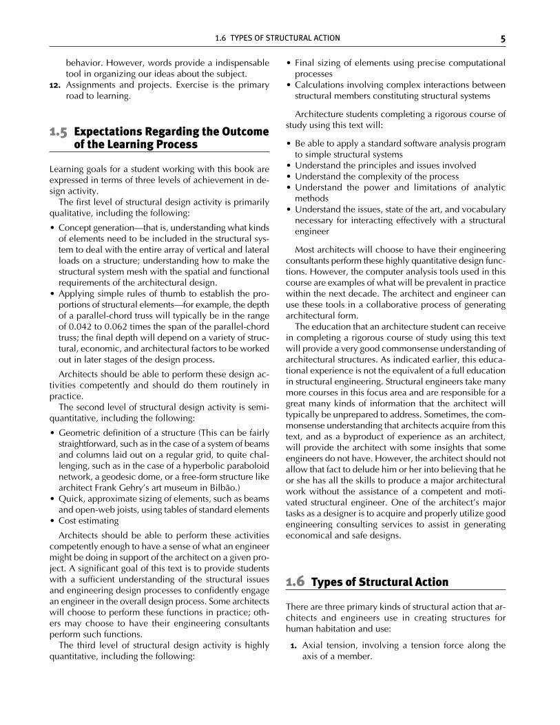
1. Axial tension, involving a tension force along theaxis of a member.
1.6 TYPES OF STRUCTURAL ACTION 5
ch01_4643 2/5/07 12:14 PM Page 5
2. Axial compression, involving a compression forcealong the axis of a member. Such members are usu-ally referred to as columns or compression struts.
3. Bending, also referred to as flexure, involving forceslateral to the axis of a member. Such members areusually referred to as beams.
In Figure 1.2(a), a 1⁄ 8 in.-diameter × 6 in.-long PVC rod is subjected to axial tension. More than 9 kg of weighthas been hung off the rod. It would have supported sub-stantially more weight, but the testing was limited byconcern about dents in the floor. In Figure 1.2(b), thesame rod is subjected to axial compression in a small test-ing device. Buckling failure occurred at 0.8 kg of axialcompression force, which is less than a tenth of what iteasily held in tension. In Figure 1.2(c), the same elementis being used in bending, where massive deformations areobserved at a lateral force of 0.4 kg. This demonstrationillustrates the hierarchy of structural efficiency: tensionmembers tend to be more efficient than compres-sion members, which tend to be more efficient than bend-ing members.
Tensile members are limited by the yield stress of thematerial. They can also be severely limited by means ofmaking connections at the ends of the members. In Fig-ure 1.2, the PVC rod was glued deep into the two sturdywooden blocks, which ensured that the end connectionswould develop most or all of the potential tensioncapacity of the rod.
Compression members are limited by the yield stressof the material and by buckling, wherein the element be-gins to radically change shape, moving laterally out fromunder the load, before the yield stress of the material isreached. (Laterally means to the side, i.e., perpendicularto the axis of the element.) The tendency to buckle can
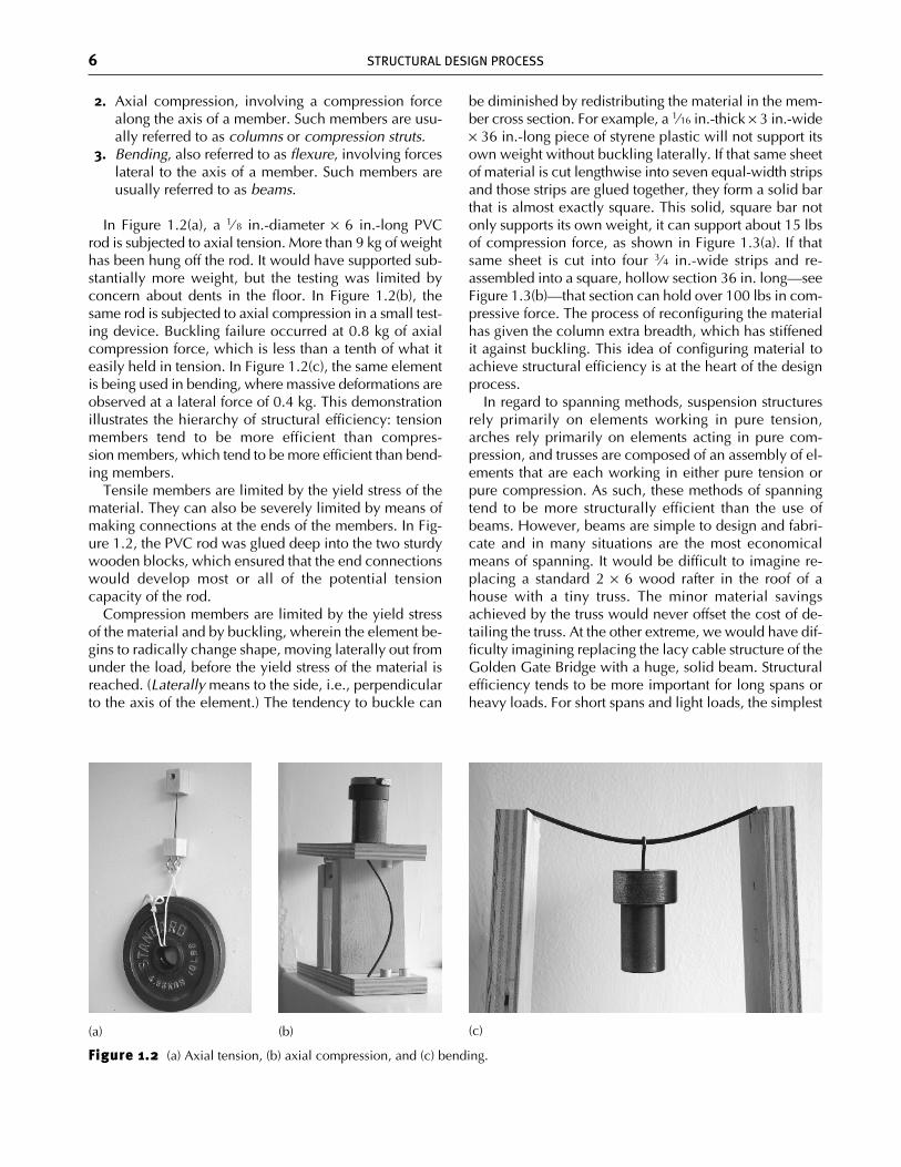
be diminished by redistributing the material in the mem-ber cross section. For example, a 1⁄16 in.-thick × 3 in.-wide× 36 in.-long piece of styrene plastic will not support itsown weight without buckling laterally. If that same sheetof material is cut lengthwise into seven equal-width stripsand those strips are glued together, they form a solid barthat is almost exactly square. This solid, square bar notonly supports its own weight, it can support about 15 lbsof compression force, as shown in Figure 1.3(a). If thatsame sheet is cut into four 3⁄4 in.-wide strips and re-assembled into a square, hollow section 36 in. long—seeFigure 1.3(b)—that section can hold over 100 lbs in com-pressive force. The process of reconfiguring the materialhas given the column extra breadth, which has stiffenedit against buckling. This idea of configuring material toachieve structural efficiency is at the heart of the designprocess.
In regard to spanning methods, suspension structuresrely primarily on elements working in pure tension,arches rely primarily on elements acting in pure com-pression, and trusses are composed of an assembly of el-ements that are each working in either pure tension orpure compression. As such, these methods of spanningtend to be more structurally efficient than the use ofbeams. However, beams are simple to design and fabri-cate and in many situations are the most economicalmeans of spanning. It would be difficult to imagine re-placing a standard 2 × 6 wood rafter in the roof of ahouse with a tiny truss. The minor material savingsachieved by the truss would never offset the cost of de-tailing the truss. At the other extreme, we would have dif-ficulty imagining replacing the lacy cable structure of theGolden Gate Bridge with a huge, solid beam. Structuralefficiency tends to be more important for long spans orheavy loads. For short spans and light loads, the simplest
6 STRUCTURAL DESIGN PROCESS
Figure 1.2 (a) Axial tension, (b) axial compression, and (c) bending.
(a) (b) (c)
ch01_4643 2/5/07 12:14 PM Page 6
and most expedient structure is generally the most eco-nomical and appropriate. How to achieve structural effi-ciency is a major theme of this book.
Bending elements are limited by leverage effects.Beams, particularly shallow beams, have a major me-chanical disadvantage relative to the applied forces. Thispoint is addressed in more detailed and more preciseterms in later chapters. In the meantime, simple experi-ence and intuition can be used to develop the idea ofleverage. It can be clear from experience that the shapeof a structural element is important and that “structuraldepth” is crucial to structural performance. For example,if we want a strong beam, we will set a wood 2 × 10 onedge to resist gravity forces. Yet if we wanted to break thesame board, we would lay it on its side. Laying the boardon its side reduces both the strength and the stiffness ofthe element in responding to gravity forces. A wide, flatbeam is not only weaker, that is, easier to break, but alsoless stiff. Typically in our culture, we associate stiffnesswith strength. When we pound on a wall or jump up anddown on a floor and perceive very little movement, weassume that these elements are very strong. Althoughthere is a correlation between stiffness and strength, thecorrelation between those properties is far from perfect.
For example, we can create a broad, flat cantilever beamthat is both flexible enough and strong enough to be usedas a diving board. This apparently contradictory set oftraits is also useful in the leaf springs of a motor vehicle.However, in structural applications, stiffness and strengthwill be highly correlated, and we will be seeking to cre-ate structures that are both strong and very stiff. Most ofthe time the primary motive for seeking stiffness is eitherto reduce distracting vibrations or to improve the per-ception of quality on the part of the building occupants.Sometimes, however, the desirability of stiffness goes be-yond perception and becomes a life safety issue. For ex-ample, an overflexible flat roof may begin to deflectunder the weight of a deluge of rain. The deflection cre-ates a bowl shape that causes more water to accumulate.The added water causes a deeper bowl to form, resultingin an even greater accumulation. This process is referredto as ponding. Ponding has more to do with the stiffnessof the roof than with the initial strength of the roof. Tworoofs may both be rated to carry the prescribed snow orlive load, but one may be flexible enough to accumulatewater and the other stiff enough to resist that accumula-tion. Ponding takes the importance of stiffness beyondperception and comfort into the realm of life safety.
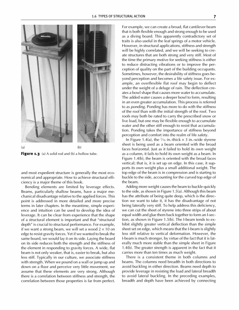
In Figure 1.4(a), the 1⁄16 in.-thick × 3 in.-wide styrenesheet is being used as a beam oriented with the broadfaces horizontal. Just as it failed to hold its own weightas a column, it fails to hold its own weight as a beam. InFigure 1.4(b), the beam is oriented with the broad facesvertical; that is, it is set up on edge. In this case, it sup-ports its own weight plus a small additional weight. Thetop edge of the beam is in compression and is starting tobuckle to the side, accounting for the curved top edge ofthe beam.
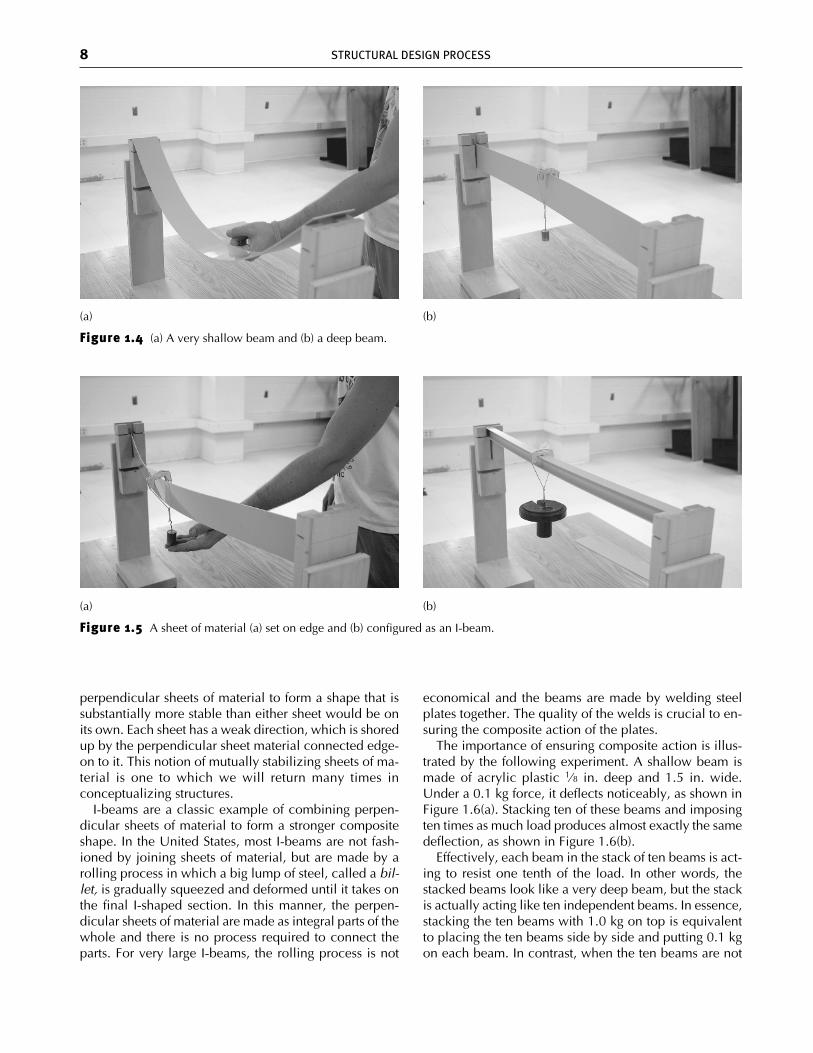
Adding more weight causes the beam to buckle quicklyto the side, as shown in Figure 1.5(a). Although this beamhas the attribute of being quite deep, which is the direc-tion we want to take it, it has the disadvantage of notbeing laterally very stiff. To help address this deficiency,we can cut the sheet of styrene into three strips of aboutequal width and glue them back together to form an I-sec-tion, as shown in Figure 1.5(b). The I-beam tends to ex-hibit slightly greater vertical deflection than the simplesheet set on edge, which means that the I-beam is slightlyless stiff relative to vertical deformation. However, theI-beam is much stronger, by virtue of the fact that it is lat-erally much more stable than the simple sheet in Figure1.4(b). The greater strength is apparent in the fact that itcarries more than ten times as much weight.
There is a consistent theme in both columns andbeams. The columns need breadth in both directions toavoid buckling in either direction. Beams need depth toprovide leverage in resisting the load and lateral breadthto avoid lateral buckling. In the preceding examples,breadth and depth have been achieved by connecting
1.6 TYPES OF STRUCTURAL ACTION 7
Figure 1.3 (a) A solid rod and (b) a hollow tube.
(a) (b)
ch01_4643 2/5/07 12:14 PM Page 7
8 STRUCTURAL DESIGN PROCESS
Figure 1.4 (a) A very shallow beam and (b) a deep beam.
(a) (b)
(a) (b)
perpendicular sheets of material to form a shape that issubstantially more stable than either sheet would be onits own. Each sheet has a weak direction, which is shoredup by the perpendicular sheet material connected edge-on to it. This notion of mutually stabilizing sheets of ma-terial is one to which we will return many times inconceptualizing structures.
I-beams are a classic example of combining perpen-dicular sheets of material to form a stronger compositeshape. In the United States, most I-beams are not fash-ioned by joining sheets of material, but are made by arolling process in which a big lump of steel, called a bil-let, is gradually squeezed and deformed until it takes onthe final I-shaped section. In this manner, the perpen-dicular sheets of material are made as integral parts of thewhole and there is no process required to connect theparts. For very large I-beams, the rolling process is not
economical and the beams are made by welding steelplates together. The quality of the welds is crucial to en-suring the composite action of the plates.
The importance of ensuring composite action is illus-trated by the following experiment. A shallow beam ismade of acrylic plastic 1⁄8 in. deep and 1.5 in. wide.Under a 0.1 kg force, it deflects noticeably, as shown inFigure 1.6(a). Stacking ten of these beams and imposingten times as much load produces almost exactly the samedeflection, as shown in Figure 1.6(b).
Effectively, each beam in the stack of ten beams is act-ing to resist one tenth of the load. In other words, thestacked beams look like a very deep beam, but the stackis actually acting like ten independent beams. In essence,stacking the ten beams with 1.0 kg on top is equivalentto placing the ten beams side by side and putting 0.1 kgon each beam. In contrast, when the ten beams are not
Figure 1.5 A sheet of material (a) set on edge and (b) configured as an I-beam.
ch01_4643 2/5/07 12:14 PM Page 8
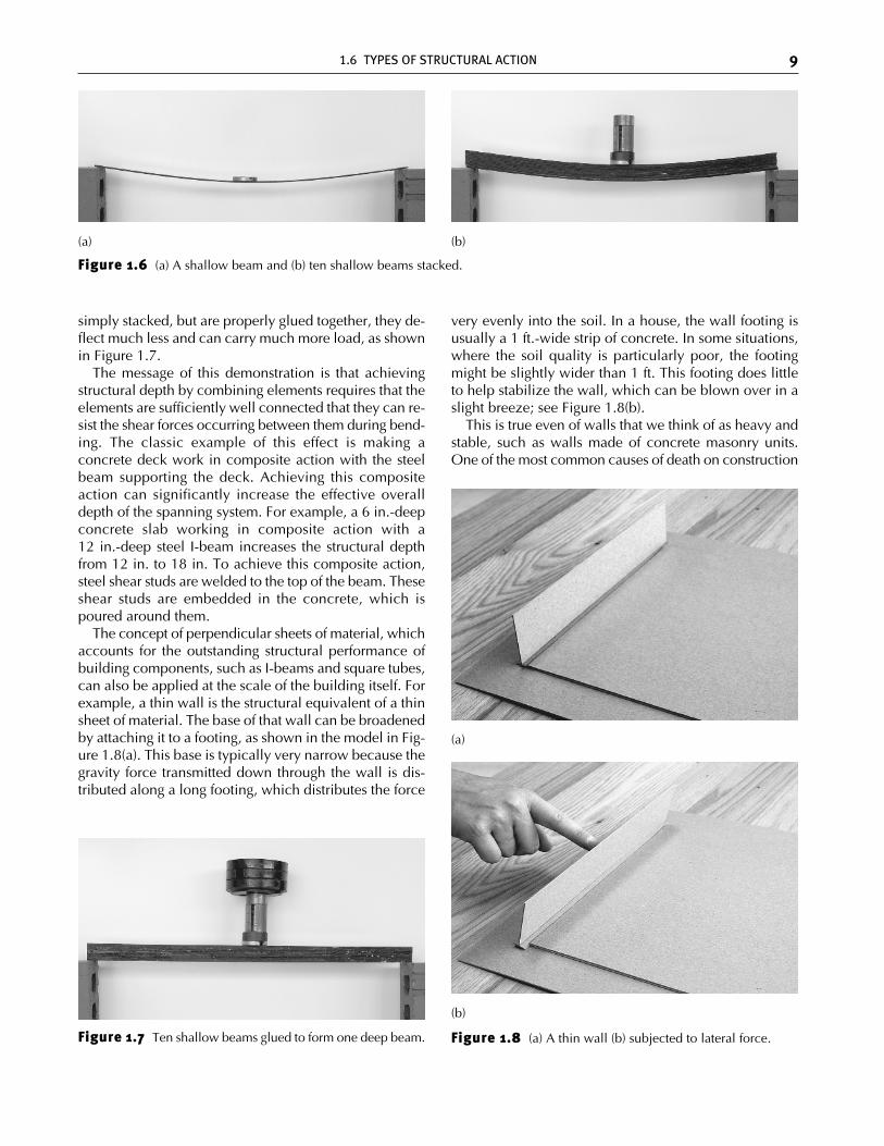
simply stacked, but are properly glued together, they de-flect much less and can carry much more load, as shownin Figure 1.7.
The message of this demonstration is that achievingstructural depth by combining elements requires that theelements are sufficiently well connected that they can re-sist the shear forces occurring between them during bend-ing. The classic example of this effect is making aconcrete deck work in composite action with the steelbeam supporting the deck. Achieving this compositeaction can significantly increase the effective overalldepth of the spanning system. For example, a 6 in.-deepconcrete slab working in composite action with a12 in.-deep steel I-beam increases the structural depthfrom 12 in. to 18 in. To achieve this composite action,steel shear studs are welded to the top of the beam. Theseshear studs are embedded in the concrete, which ispoured around them.
The concept of perpendicular sheets of material, whichaccounts for the outstanding structural performance ofbuilding components, such as I-beams and square tubes,can also be applied at the scale of the building itself. Forexample, a thin wall is the structural equivalent of a thinsheet of material. The base of that wall can be broadenedby attaching it to a footing, as shown in the model in Fig-ure 1.8(a). This base is typically very narrow because thegravity force transmitted down through the wall is dis-tributed along a long footing, which distributes the force
very evenly into the soil. In a house, the wall footing isusually a 1 ft.-wide strip of concrete. In some situations,where the soil quality is particularly poor, the footingmight be slightly wider than 1 ft. This footing does littleto help stabilize the wall, which can be blown over in aslight breeze; see Figure 1.8(b).
This is true even of walls that we think of as heavy andstable, such as walls made of concrete masonry units.One of the most common causes of death on construction
1.6 TYPES OF STRUCTURAL ACTION 9
Figure 1.6 (a) A shallow beam and (b) ten shallow beams stacked.
(a) (b)
Figure 1.7 Ten shallow beams glued to form one deep beam. Figure 1.8 (a) A thin wall (b) subjected to lateral force.
(b)
(a)
ch01_4643 2/5/07 12:14 PM Page 9

sites is the overturning of masonry walls that have notbeen properly shored up during the construction process.Clearly, an individual wall of this sort is of no structuralvalue by itself. This wall makes sense only as part of alarger system, with other parts that compensate for theweaknesses of this wall. One way to help this wall is toconnect it to other walls perpendicular to it. This is whatis normally done anyway, inasmuch as achieving an en-closed space requires more than one wall. Figure 1.9illustrates the idea. Each of the four walls is stabilized atits ends by other walls set perpendicular to it. Now theweakness of each wall is near the center of the wall,where it is far removed from the stabilizing benefits of anyperpendicular sheets of material.
The walls perpendicular to the wall being exposed towind overpressure are put in a state of shear as the wallbeing loaded leans against them. These perpendicularwalls are sometimes referred to as shear walls. They mustbe properly constituted to resist a shearing force. Manyof the walls used in standard construction are capable ofresisting substantial shear force. However, this is not al-
ways true. For example, classic post-and-beam con-struction is very poor in resisting lateral forces, as illus-trated in Figure 1.10.
Standard wood stud construction eliminates this defor-mation of the wood frame by adding sheets of material inthe plane of the wall, such as plywood or oriented strandboard (OSB), which provide the diagonal forces to keepthe wall from racking. See Figures 1.11, 1.12, and 1.13.
The composite construction of sheet material, such asplywood or OSB, with studs is another example of mu-tually bracing, perpendicular sheets of material, in thatthe studs are set with their long cross-sectional dimensionperpendicular to the OSB sheet. The OSB sheet is verythin and very vulnerable to lateral buckling, similar to thatobserved in the thin sheet of plastic that we tried to useas a beam in Figure 1.5. By itself, the OSB is not a veryeffective structural element, but when braced frequentlyby studs, its structural effectiveness is greatly enhanced.OSB and plywood are typically considered as providingthe shear resistance for walls in one- or two-story build-ings, using only nails to connect the OSB or plywood to
10 STRUCTURAL DESIGN PROCESS
Figure 1.9 (a, b) Walls stabilizing each other at the ends.
(b)(a)
Figure 1.10 (a, b) Post-and-beam construction deforming (racking) under shearing load.
(b)(a)
ch01_4643 2/5/07 12:14 PM Page 10
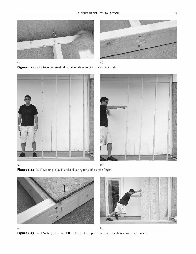
Figure 1.12 (a, b) Racking of studs under shearing force of a single finger.
(b)(a)
1.6 TYPES OF STRUCTURAL ACTION 11
Figure 1.11 (a, b) Sstandard method of nailing shoe and top plate to the studs.
(a) (b)
Figure 1.13 (a, b) Nailing sheets of OSB to studs, a top a plate, and shoe to enhance lateral resistance.
(b)(a)
ch01_4643 2/5/07 12:14 PM Page 11
12 STRUCTURAL DESIGN PROCESS
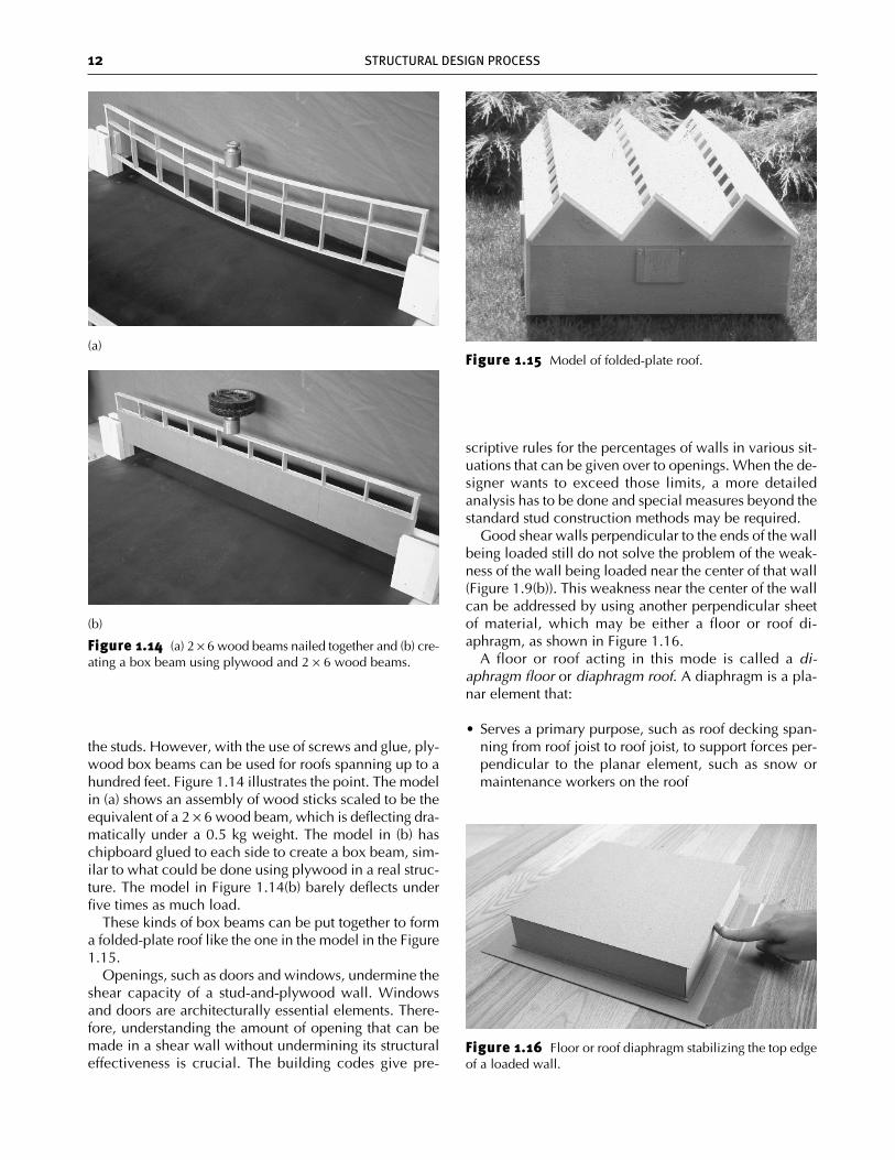
Figure 1.14 (a) 2 × 6 wood beams nailed together and (b) cre-ating a box beam using plywood and 2 × 6 wood beams.
(b)
(a)Figure 1.15 Model of folded-plate roof.
Figure 1.16 Floor or roof diaphragm stabilizing the top edgeof a loaded wall.
the studs. However, with the use of screws and glue, ply-wood box beams can be used for roofs spanning up to ahundred feet. Figure 1.14 illustrates the point. The modelin (a) shows an assembly of wood sticks scaled to be theequivalent of a 2 × 6 wood beam, which is deflecting dra-matically under a 0.5 kg weight. The model in (b) haschipboard glued to each side to create a box beam, sim-ilar to what could be done using plywood in a real struc-ture. The model in Figure 1.14(b) barely deflects underfive times as much load.
These kinds of box beams can be put together to forma folded-plate roof like the one in the model in the Figure1.15.
Openings, such as doors and windows, undermine theshear capacity of a stud-and-plywood wall. Windowsand doors are architecturally essential elements. There-fore, understanding the amount of opening that can bemade in a shear wall without undermining its structuraleffectiveness is crucial. The building codes give pre-
scriptive rules for the percentages of walls in various sit-uations that can be given over to openings. When the de-signer wants to exceed those limits, a more detailedanalysis has to be done and special measures beyond thestandard stud construction methods may be required.
Good shear walls perpendicular to the ends of the wallbeing loaded still do not solve the problem of the weak-ness of the wall being loaded near the center of that wall(Figure 1.9(b)). This weakness near the center of the wallcan be addressed by using another perpendicular sheetof material, which may be either a floor or roof di-aphragm, as shown in Figure 1.16.
A floor or roof acting in this mode is called a di-aphragm floor or diaphragm roof. A diaphragm is a pla-nar element that:
• Serves a primary purpose, such as roof decking span-ning from roof joist to roof joist, to support forces per-pendicular to the planar element, such as snow ormaintenance workers on the roof
ch01_4643 2/5/07 12:14 PM Page 12

Figure 1.17 Forces on loaded wall, diaphragm roof, shear walls, and footings.
• Serves a secondary role as a deep beam resisting forcesparallel to the plane of the element
In Figure 1.16, the force parallel to the plane of the roofdecking is created by the wall pressing against the edgeof the roof. The diagram in Figure 1.17 suggests the na-ture of the interaction, wherein:
• The upper edge of the loaded wall presses against theedge of the roof.
• The diaphragm roof acts as a very deep, horizontalbeam carrying the horizontal force on its edge to thetops of the side walls (i.e., the walls parallel to the di-rection of the force).
• The side walls serve as shear walls, carrying the forcedown to the footings.
• The horizontal force of the roof diaphragm along thetop edge of one of the side shear walls, combined withthe horizontal force in the other direction of the footing
1.6 TYPES OF STRUCTURAL ACTION 13
ch01_4643 2/5/07 12:14 PM Page 13
on the bottom of the side shear wall, tends to make theshear wall rotate. To avoid this, the footing must alsocreate hold-down forces on the shear wall on thewindward end of the shear wall and upward forces onthe leeward end of the shear wall. These forces haveto do with the overturning effect, which can be equi-librated only by the self-weight of the wall and of thefooting.
The properties that allow a roof to work as a horizon-tal beam, that is, as a diaphragm, are the same propertiesthat allow a wall to work as a cantilevered beam relativeto forces parallel to the wall; that is, to work as a shearwall. Shear walls could be referred to as diaphragm walls,or diaphragm roofs as shear roofs. This text, however,sticks to the custom of associating the word shear withwalls and the word diaphragm with roofs and floors.
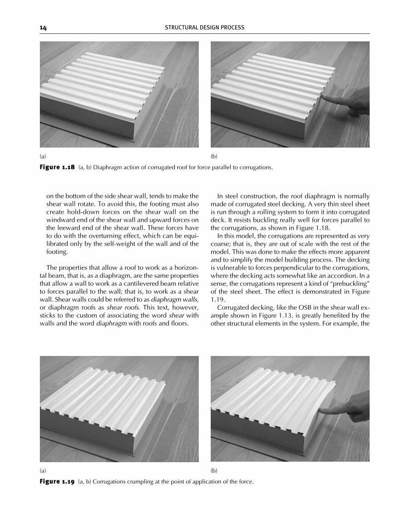
In steel construction, the roof diaphragm is normallymade of corrugated steel decking. A very thin steel sheetis run through a rolling system to form it into corrugateddeck. It resists buckling really well for forces parallel tothe corrugations, as shown in Figure 1.18.
In this model, the corrugations are represented as verycoarse; that is, they are out of scale with the rest of themodel. This was done to make the effects more apparentand to simplify the model building process. The deckingis vulnerable to forces perpendicular to the corrugations,where the decking acts somewhat like an accordion. In asense, the corrugations represent a kind of “prebuckling”of the steel sheet. The effect is demonstrated in Figure1.19.
Corrugated decking, like the OSB in the shear wall ex-ample shown in Figure 1.13, is greatly benefited by theother structural elements in the system. For example, the
14 STRUCTURAL DESIGN PROCESS
Figure 1.18 (a, b) Diaphragm action of corrugated roof for force parallel to corrugations.
(a) (b)
Figure 1.19 (a, b) Corrugations crumpling at the point of application of the force.
(a) (b)
ch01_4643 2/5/07 12:14 PM Page 14
1.6 TYPES OF STRUCTURAL ACTION 15
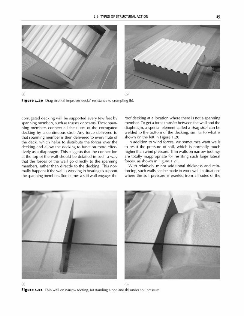
Figure 1.20 Drag strut (a) improves decks’ resistance to crumpling (b).
(b)
(b)(a)
corrugated decking will be supported every few feet byspanning members, such as trusses or beams. These span-ning members connect all the flutes of the corrugateddecking by a continuous strut. Any force delivered tothat spanning member is then delivered to every flute ofthe deck, which helps to distribute the forces over thedecking and allow the decking to function more effec-tively as a diaphragm. This suggests that the connectionat the top of the wall should be detailed in such a waythat the forces of the wall go directly to the spanningmembers, rather than directly to the decking. This nor-mally happens if the wall is working in bearing to supportthe spanning members. Sometimes a stiff wall engages the
roof decking at a location where there is not a spanningmember. To get a force transfer between the wall and thediaphragm, a special element called a drag strut can bewelded to the bottom of the decking, similar to what isshown on the left in Figure 1.20.
In addition to wind forces, we sometimes want wallsto resist the pressure of soil, which is normally muchhigher than wind pressure. Thin walls on narrow footingsare totally inappropriate for resisting such large lateralforces, as shown in Figure 1.21.
With relatively minor additional thickness and rein-forcing, such walls can be made to work well in situationswhere the soil pressure is exerted from all sides of the
Figure 1.21 Thin wall on narrow footing, (a) standing alone and (b) under soil pressure.
(a)
ch01_4643 2/5/07 12:14 PM Page 15
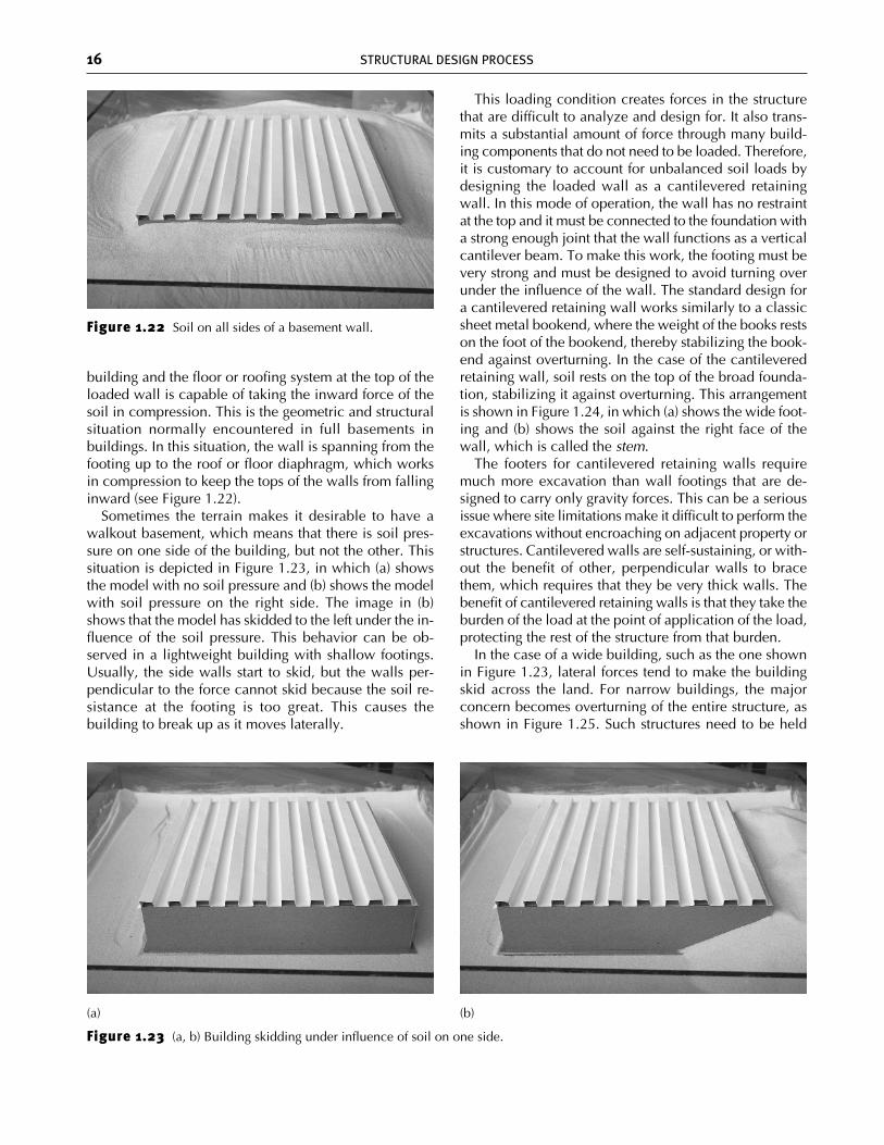
building and the floor or roofing system at the top of theloaded wall is capable of taking the inward force of thesoil in compression. This is the geometric and structuralsituation normally encountered in full basements inbuildings. In this situation, the wall is spanning from thefooting up to the roof or floor diaphragm, which worksin compression to keep the tops of the walls from fallinginward (see Figure 1.22).
Sometimes the terrain makes it desirable to have awalkout basement, which means that there is soil pres-sure on one side of the building, but not the other. Thissituation is depicted in Figure 1.23, in which (a) showsthe model with no soil pressure and (b) shows the modelwith soil pressure on the right side. The image in (b)shows that the model has skidded to the left under the in-fluence of the soil pressure. This behavior can be ob-served in a lightweight building with shallow footings.Usually, the side walls start to skid, but the walls per-pendicular to the force cannot skid because the soil re-sistance at the footing is too great. This causes thebuilding to break up as it moves laterally.
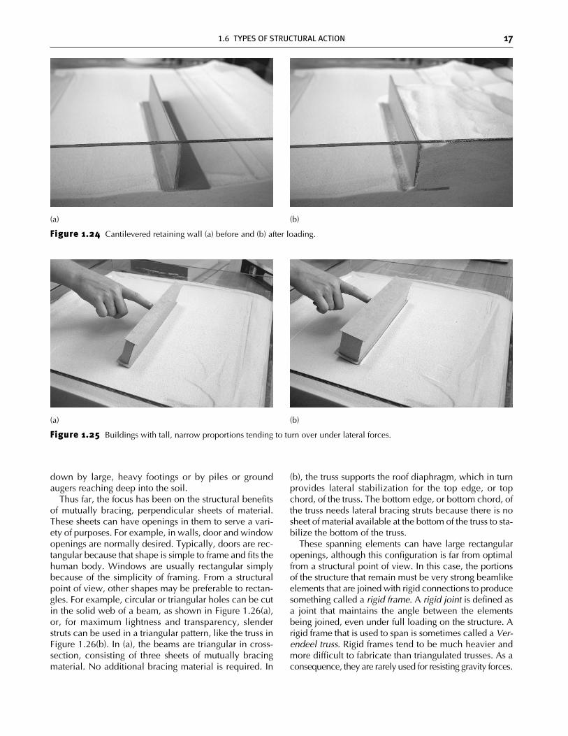
This loading condition creates forces in the structurethat are difficult to analyze and design for. It also trans-mits a substantial amount of force through many build-ing components that do not need to be loaded. Therefore,it is customary to account for unbalanced soil loads bydesigning the loaded wall as a cantilevered retainingwall. In this mode of operation, the wall has no restraintat the top and it must be connected to the foundation witha strong enough joint that the wall functions as a verticalcantilever beam. To make this work, the footing must bevery strong and must be designed to avoid turning overunder the influence of the wall. The standard design fora cantilevered retaining wall works similarly to a classicsheet metal bookend, where the weight of the books restson the foot of the bookend, thereby stabilizing the book-end against overturning. In the case of the cantileveredretaining wall, soil rests on the top of the broad founda-tion, stabilizing it against overturning. This arrangementis shown in Figure 1.24, in which (a) shows the wide foot-ing and (b) shows the soil against the right face of thewall, which is called the stem.
The footers for cantilevered retaining walls requiremuch more excavation than wall footings that are de-signed to carry only gravity forces. This can be a seriousissue where site limitations make it difficult to perform theexcavations without encroaching on adjacent property orstructures. Cantilevered walls are self-sustaining, or with-out the benefit of other, perpendicular walls to bracethem, which requires that they be very thick walls. Thebenefit of cantilevered retaining walls is that they take theburden of the load at the point of application of the load,protecting the rest of the structure from that burden.
In the case of a wide building, such as the one shownin Figure 1.23, lateral forces tend to make the buildingskid across the land. For narrow buildings, the majorconcern becomes overturning of the entire structure, asshown in Figure 1.25. Such structures need to be held
16 STRUCTURAL DESIGN PROCESS
Figure 1.22 Soil on all sides of a basement wall.
Figure 1.23 (a, b) Building skidding under influence of soil on one side.
(b)(a)
ch01_4643 2/5/07 12:14 PM Page 16
1.6 TYPES OF STRUCTURAL ACTION 17
Figure 1.24 Cantilevered retaining wall (a) before and (b) after loading.
(b)(a)
Figure 1.25 Buildings with tall, narrow proportions tending to turn over under lateral forces.
(b)(a)
down by large, heavy footings or by piles or groundaugers reaching deep into the soil.
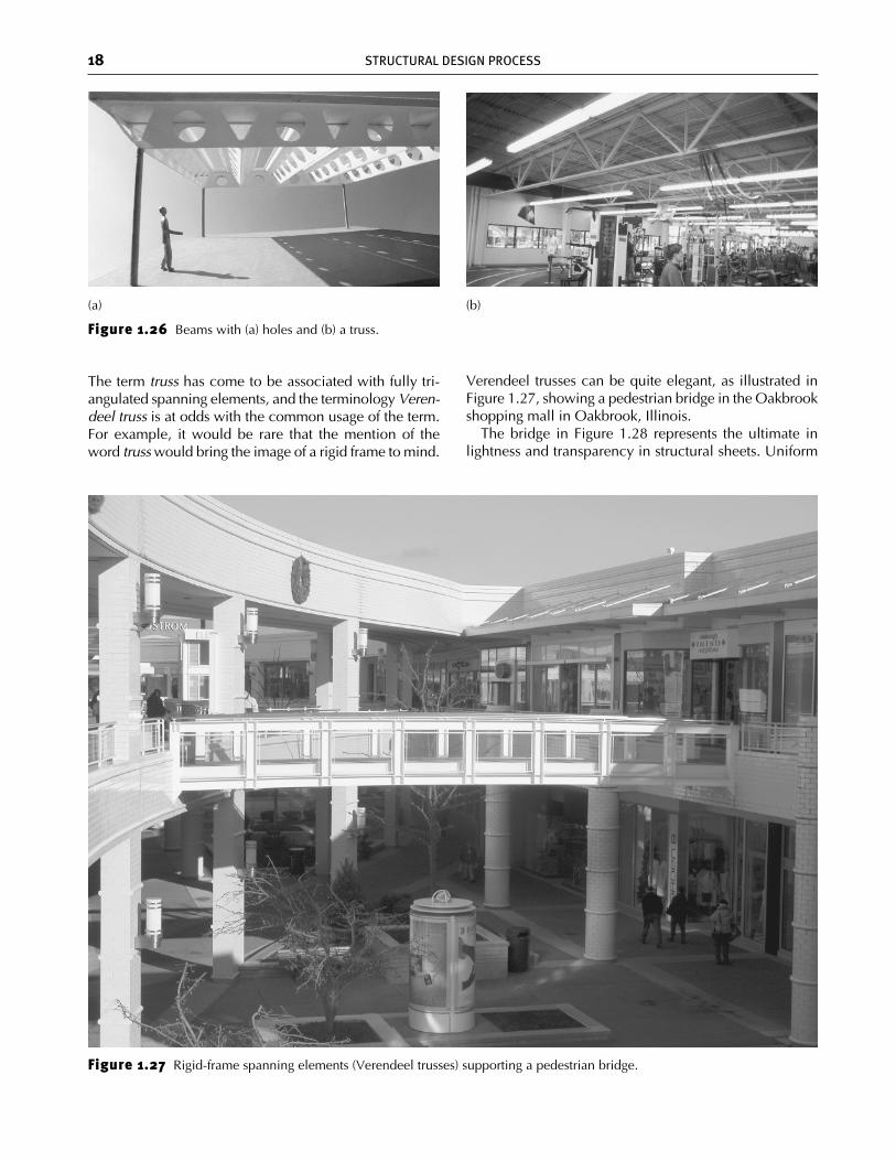
Thus far, the focus has been on the structural benefitsof mutually bracing, perpendicular sheets of material.These sheets can have openings in them to serve a vari-ety of purposes. For example, in walls, door and windowopenings are normally desired. Typically, doors are rec-tangular because that shape is simple to frame and fits thehuman body. Windows are usually rectangular simplybecause of the simplicity of framing. From a structuralpoint of view, other shapes may be preferable to rectan-gles. For example, circular or triangular holes can be cutin the solid web of a beam, as shown in Figure 1.26(a),or, for maximum lightness and transparency, slenderstruts can be used in a triangular pattern, like the truss inFigure 1.26(b). In (a), the beams are triangular in cross-section, consisting of three sheets of mutually bracingmaterial. No additional bracing material is required. In
(b), the truss supports the roof diaphragm, which in turnprovides lateral stabilization for the top edge, or topchord, of the truss. The bottom edge, or bottom chord, ofthe truss needs lateral bracing struts because there is nosheet of material available at the bottom of the truss to sta-bilize the bottom of the truss.
These spanning elements can have large rectangularopenings, although this configuration is far from optimalfrom a structural point of view. In this case, the portionsof the structure that remain must be very strong beamlikeelements that are joined with rigid connections to producesomething called a rigid frame. A rigid joint is defined asa joint that maintains the angle between the elementsbeing joined, even under full loading on the structure. Arigid frame that is used to span is sometimes called a Ver-endeel truss. Rigid frames tend to be much heavier andmore difficult to fabricate than triangulated trusses. As aconsequence, they are rarely used for resisting gravity forces.
ch01_4643 2/5/07 12:14 PM Page 17
18 STRUCTURAL DESIGN PROCESS
Figure 1.27 Rigid-frame spanning elements (Verendeel trusses) supporting a pedestrian bridge.
Figure 1.26 Beams with (a) holes and (b) a truss.
(b)(a)
The term truss has come to be associated with fully tri-angulated spanning elements, and the terminology Veren-deel truss is at odds with the common usage of the term.For example, it would be rare that the mention of theword truss would bring the image of a rigid frame to mind.
Verendeel trusses can be quite elegant, as illustrated inFigure 1.27, showing a pedestrian bridge in the Oakbrookshopping mall in Oakbrook, Illinois.
The bridge in Figure 1.28 represents the ultimate inlightness and transparency in structural sheets. Uniform
ch01_4643 2/5/07 12:14 PM Page 18
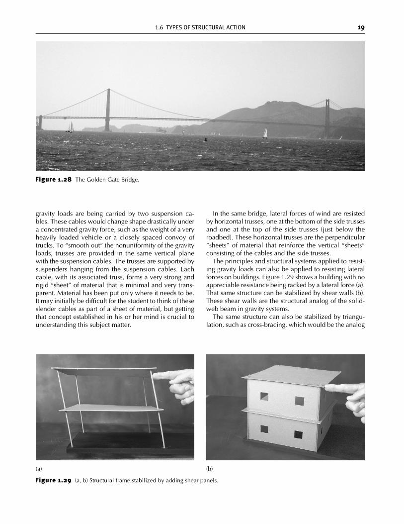
gravity loads are being carried by two suspension ca-bles. These cables would change shape drastically undera concentrated gravity force, such as the weight of a veryheavily loaded vehicle or a closely spaced convoy oftrucks. To “smooth out” the nonuniformity of the gravityloads, trusses are provided in the same vertical planewith the suspension cables. The trusses are supported bysuspenders hanging from the suspension cables. Eachcable, with its associated truss, forms a very strong andrigid “sheet” of material that is minimal and very trans-parent. Material has been put only where it needs to be.It may initially be difficult for the student to think of theseslender cables as part of a sheet of material, but gettingthat concept established in his or her mind is crucial tounderstanding this subject matter.
In the same bridge, lateral forces of wind are resistedby horizontal trusses, one at the bottom of the side trussesand one at the top of the side trusses (just below theroadbed). These horizontal trusses are the perpendicular“sheets” of material that reinforce the vertical “sheets”consisting of the cables and the side trusses.
The principles and structural systems applied to resist-ing gravity loads can also be applied to resisting lateralforces on buildings. Figure 1.29 shows a building with noappreciable resistance being racked by a lateral force (a).That same structure can be stabilized by shear walls (b).These shear walls are the structural analog of the solid-web beam in gravity systems.
The same structure can also be stabilized by triangu-lation, such as cross-bracing, which would be the analog
1.6 TYPES OF STRUCTURAL ACTION 19
Figure 1.28 The Golden Gate Bridge.
Figure 1.29 (a, b) Structural frame stabilized by adding shear panels.
(b)(a)
ch01_4643 2/5/07 12:14 PM Page 19
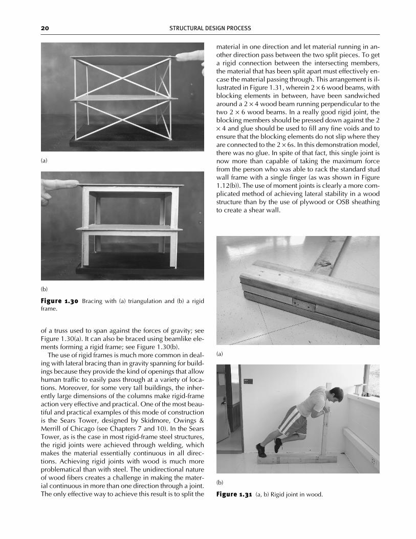
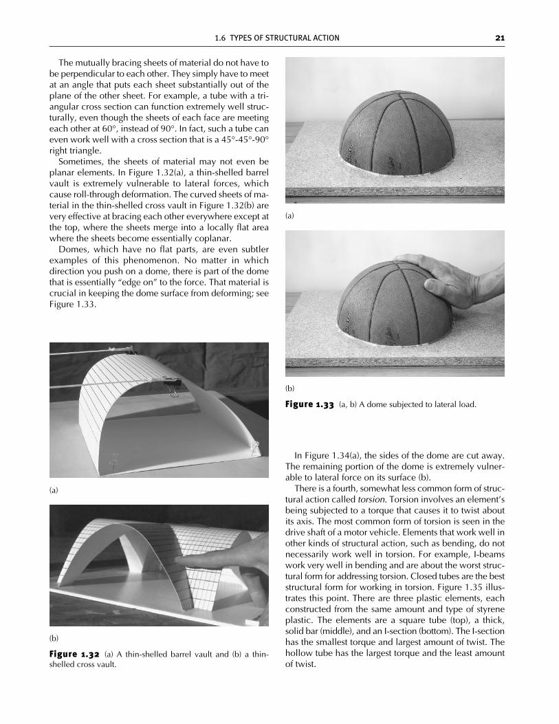
of a truss used to span against the forces of gravity; seeFigure 1.30(a). It can also be braced using beamlike ele-ments forming a rigid frame; see Figure 1.30(b).
The use of rigid frames is much more common in deal-ing with lateral bracing than in gravity spanning for build-ings because they provide the kind of openings that allowhuman traffic to easily pass through at a variety of loca-tions. Moreover, for some very tall buildings, the inher-ently large dimensions of the columns make rigid-frameaction very effective and practical. One of the most beau-tiful and practical examples of this mode of constructionis the Sears Tower, designed by Skidmore, Owings &Merrill of Chicago (see Chapters 7 and 10). In the SearsTower, as is the case in most rigid-frame steel structures,the rigid joints were achieved through welding, whichmakes the material essentially continuous in all direc-tions. Achieving rigid joints with wood is much moreproblematical than with steel. The unidirectional natureof wood fibers creates a challenge in making the mater-ial continuous in more than one direction through a joint.The only effective way to achieve this result is to split the
material in one direction and let material running in an-other direction pass between the two split pieces. To geta rigid connection between the intersecting members,the material that has been split apart must effectively en-case the material passing through. This arrangement is il-lustrated in Figure 1.31, wherein 2 × 6 wood beams, withblocking elements in between, have been sandwichedaround a 2 × 4 wood beam running perpendicular to thetwo 2 × 6 wood beams. In a really good rigid joint, theblocking members should be pressed down against the 2× 4 and glue should be used to fill any fine voids and toensure that the blocking elements do not slip where theyare connected to the 2 × 6s. In this demonstration model,there was no glue. In spite of that fact, this single joint isnow more than capable of taking the maximum forcefrom the person who was able to rack the standard studwall frame with a single finger (as was shown in Figure1.12(b)). The use of moment joints is clearly a more com-plicated method of achieving lateral stability in a woodstructure than by the use of plywood or OSB sheathingto create a shear wall.
20 STRUCTURAL DESIGN PROCESS
Figure 1.30 Bracing with (a) triangulation and (b) a rigidframe.
(b)
(a)
Figure 1.31 (a, b) Rigid joint in wood.
(b)
(a)
ch01_4643 2/5/07 12:14 PM Page 20
The mutually bracing sheets of material do not have tobe perpendicular to each other. They simply have to meetat an angle that puts each sheet substantially out of theplane of the other sheet. For example, a tube with a tri-angular cross section can function extremely well struc-turally, even though the sheets of each face are meetingeach other at 60°, instead of 90°. In fact, such a tube caneven work well with a cross section that is a 45°-45°-90°right triangle.
Sometimes, the sheets of material may not even beplanar elements. In Figure 1.32(a), a thin-shelled barrelvault is extremely vulnerable to lateral forces, whichcause roll-through deformation. The curved sheets of ma-terial in the thin-shelled cross vault in Figure 1.32(b) arevery effective at bracing each other everywhere except atthe top, where the sheets merge into a locally flat areawhere the sheets become essentially coplanar.
Domes, which have no flat parts, are even subtlerexamples of this phenomenon. No matter in whichdirection you push on a dome, there is part of the domethat is essentially “edge on” to the force. That material iscrucial in keeping the dome surface from deforming; seeFigure 1.33.
In Figure 1.34(a), the sides of the dome are cut away.The remaining portion of the dome is extremely vulner-able to lateral force on its surface (b).
There is a fourth, somewhat less common form of struc-tural action called torsion. Torsion involves an element’sbeing subjected to a torque that causes it to twist aboutits axis. The most common form of torsion is seen in thedrive shaft of a motor vehicle. Elements that work well inother kinds of structural action, such as bending, do notnecessarily work well in torsion. For example, I-beamswork very well in bending and are about the worst struc-tural form for addressing torsion. Closed tubes are the beststructural form for working in torsion. Figure 1.35 illus-trates this point. There are three plastic elements, eachconstructed from the same amount and type of styreneplastic. The elements are a square tube (top), a thick,solid bar (middle), and an I-section (bottom). The I-sectionhas the smallest torque and largest amount of twist. Thehollow tube has the largest torque and the least amountof twist.
1.6 TYPES OF STRUCTURAL ACTION 21
Figure 1.32 (a) A thin-shelled barrel vault and (b) a thin-shelled cross vault.
(b)
(a)
Figure 1.33 (a, b) A dome subjected to lateral load.
(b)
(a)
ch01_4643 2/5/07 12:14 PM Page 21
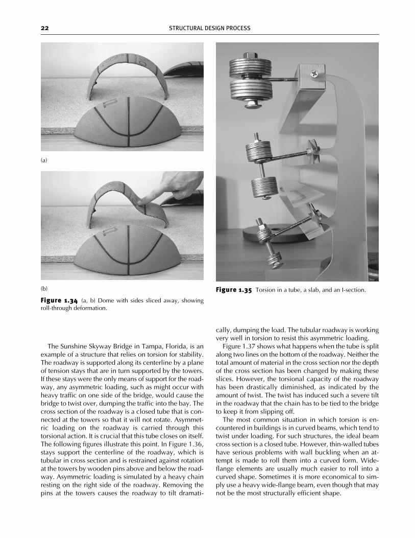
The Sunshine Skyway Bridge in Tampa, Florida, is anexample of a structure that relies on torsion for stability.The roadway is supported along its centerline by a planeof tension stays that are in turn supported by the towers.If these stays were the only means of support for the road-way, any asymmetric loading, such as might occur withheavy traffic on one side of the bridge, would cause thebridge to twist over, dumping the traffic into the bay. Thecross section of the roadway is a closed tube that is con-nected at the towers so that it will not rotate. Asymmet-ric loading on the roadway is carried through thistorsional action. It is crucial that this tube closes on itself.The following figures illustrate this point. In Figure 1.36,stays support the centerline of the roadway, which istubular in cross section and is restrained against rotationat the towers by wooden pins above and below the road-way. Asymmetric loading is simulated by a heavy chainresting on the right side of the roadway. Removing thepins at the towers causes the roadway to tilt dramati-
cally, dumping the load. The tubular roadway is workingvery well in torsion to resist this asymmetric loading.
Figure 1.37 shows what happens when the tube is splitalong two lines on the bottom of the roadway. Neither thetotal amount of material in the cross section nor the depthof the cross section has been changed by making theseslices. However, the torsional capacity of the roadwayhas been drastically diminished, as indicated by theamount of twist. The twist has induced such a severe tiltin the roadway that the chain has to be tied to the bridgeto keep it from slipping off.
The most common situation in which torsion is en-countered in buildings is in curved beams, which tend totwist under loading. For such structures, the ideal beamcross section is a closed tube. However, thin-walled tubeshave serious problems with wall buckling when an at-tempt is made to roll them into a curved form. Wide-flange elements are usually much easier to roll into acurved shape. Sometimes it is more economical to sim-ply use a heavy wide-flange beam, even though that maynot be the most structurally efficient shape.
22 STRUCTURAL DESIGN PROCESS
Figure 1.34 (a, b) Dome with sides sliced away, showingroll-through deformation.
(b)
(a)
Figure 1.35 Torsion in a tube, a slab, and an I-section.
ch01_4643 2/5/07 12:14 PM Page 22
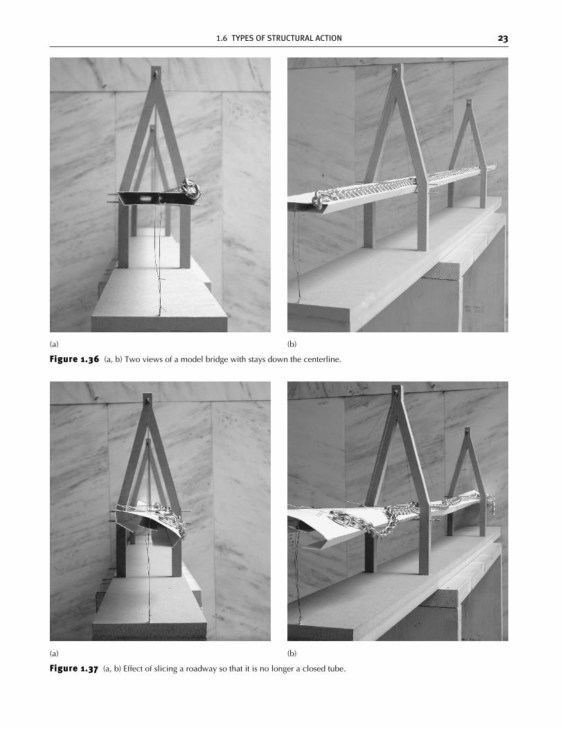
Figure 1.37 (a, b) Effect of slicing a roadway so that it is no longer a closed tube.
(a) (b)
1.6 TYPES OF STRUCTURAL ACTION 23
Figure 1.36 (a, b) Two views of a model bridge with stays down the centerline.
(a) (b)
ch01_4643 2/5/07 12:14 PM Page 23
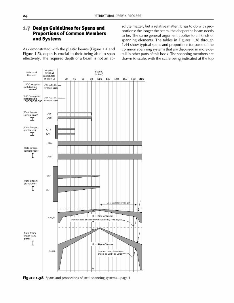
1.7 Design Guidelines for Spans andProportions of Common Membersand Systems
As demonstrated with the plastic beams (Figure 1.4 andFigure 1.5), depth is crucial to their being able to spaneffectively. The required depth of a beam is not an ab-
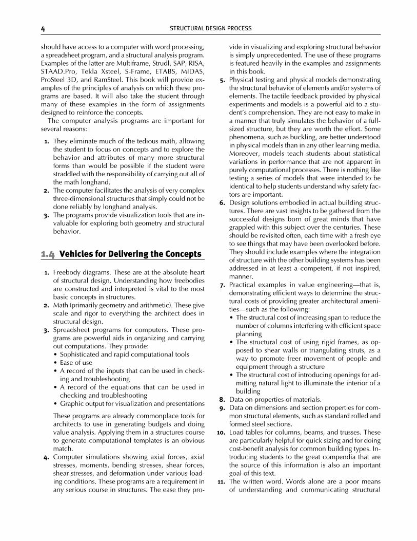
solute matter, but a relative matter. It has to do with pro-portions: the longer the beam, the deeper the beam needsto be. The same general argument applies to all kinds ofspanning elements. The tables in Figures 1.38 through1.44 show typical spans and proportions for some of thecommon spanning systems that are discussed in more de-tail in other parts of this book. The spanning members aredrawn to scale, with the scale being indicated at the top
24 STRUCTURAL DESIGN PROCESS
Figure 1.38 Spans and proportions of steel spanning systems—page 1.
ch01_4643 2/5/07 12:14 PM Page 24
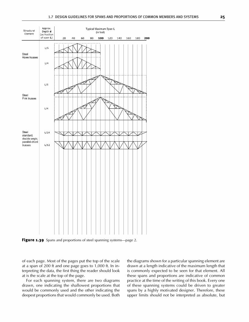
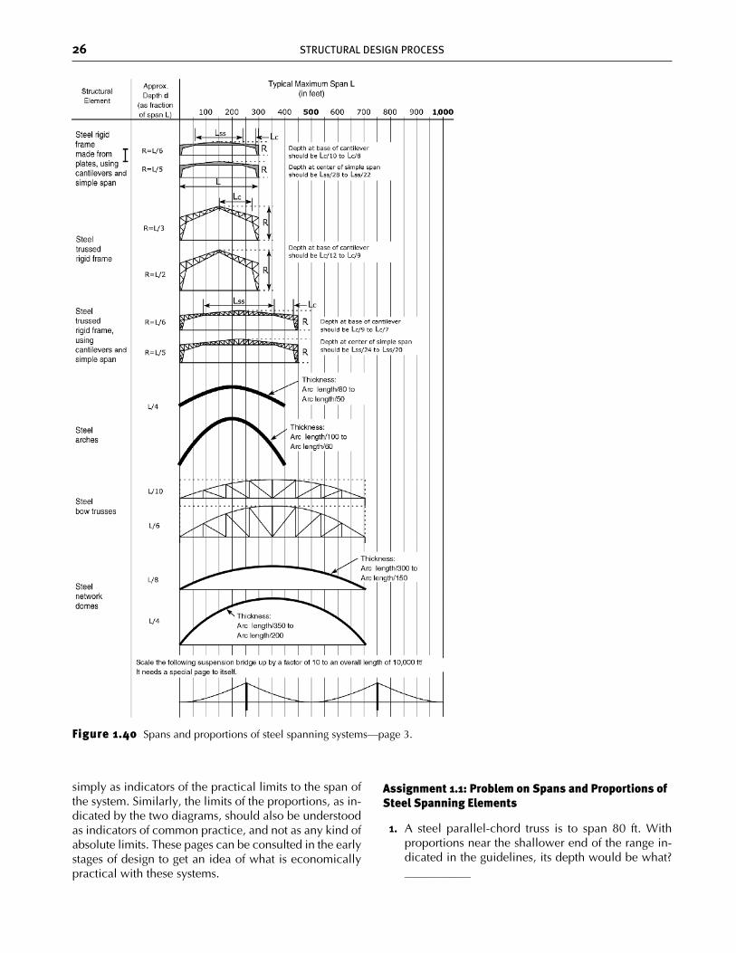
of each page. Most of the pages put the top of the scaleat a span of 200 ft and one page goes to 1,000 ft. In in-terpreting the data, the first thing the reader should lookat is the scale at the top of the page.
For each spanning system, there are two diagramsdrawn, one indicating the shallowest proportions thatwould be commonly used and the other indicating thedeepest proportions that would commonly be used. Both
the diagrams shown for a particular spanning element aredrawn at a length indicative of the maximum length thatis commonly expected to be seen for that element. Allthese spans and proportions are indicative of commonpractice at the time of the writing of this book. Every oneof these spanning systems could be driven to greaterspans by a highly motivated designer. Therefore, theseupper limits should not be interpreted as absolute, but
1.7 DESIGN GUIDELINES FOR SPANS AND PROPORTIONS OF COMMON MEMBERS AND SYSTEMS 25
Figure 1.39 Spans and proportions of steel spanning systems—page 2.
ch01_4643 2/5/07 12:14 PM Page 25
26 STRUCTURAL DESIGN PROCESS
Figure 1.40 Spans and proportions of steel spanning systems—page 3.
simply as indicators of the practical limits to the span ofthe system. Similarly, the limits of the proportions, as in-dicated by the two diagrams, should also be understoodas indicators of common practice, and not as any kind ofabsolute limits. These pages can be consulted in the earlystages of design to get an idea of what is economicallypractical with these systems.
Assignment 1.1: Problem on Spans and Proportions ofSteel Spanning Elements
1. A steel parallel-chord truss is to span 80 ft. With proportions near the shallower end of the range in-dicated in the guidelines, its depth would be what?___________
ch01_4643 2/5/07 12:14 PM Page 26
1.7 DESIGN GUIDELINES FOR SPANS AND PROPORTIONS OF COMMON MEMBERS AND SYSTEMS 27
Typical Maximum Span L(in feet)
20 40 60 80 100 120 140 160 180 200
StructuralElement
2 1/4� actual(3� nominal)
wood planking
3� actual(4� nominal)
wood planking
3 3/4� actual(5� nominal)
wood planking
Solid-sawnwood joists
Stressed-skinwood panels
(fastenedand glued)
Wood I-joist(glued)
Laminated-veneerlumber
(LVL)
Glue-laminated
beams(glulams)
Woodbox beams
(fastenedand glued)
Plywoodfolded plates
(fastenedand glued)
Woodroof
trusses
Woodparallel-chord
floortrusses
Cross-sectionalShape
L/52
L/52
L/52
L/20
L/16
L/30
L/24
L/26
L/20
L/15
L/20
L/16
L/20
L/16
L/18
L/9
L/6
L/4
L/20
L/12
L/18
Approx.Depth d
(as fraction
of span L)
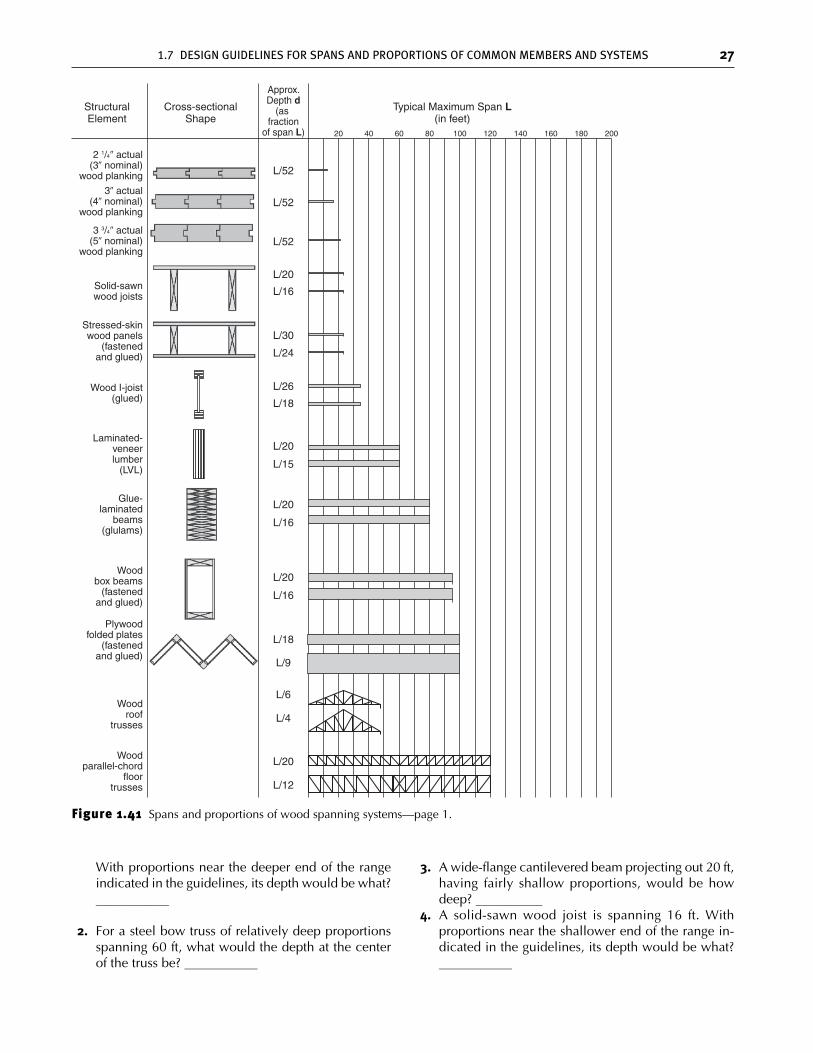
Figure 1.41 Spans and proportions of wood spanning systems—page 1.
With proportions near the deeper end of the rangeindicated in the guidelines, its depth would be what?___________
2. For a steel bow truss of relatively deep proportionsspanning 60 ft, what would the depth at the centerof the truss be? ___________
3. A wide-flange cantilevered beam projecting out 20 ft,having fairly shallow proportions, would be howdeep? __________
4. A solid-sawn wood joist is spanning 16 ft. Withproportions near the shallower end of the range in-dicated in the guidelines, its depth would be what?___________
ch01_4643 2/5/07 12:14 PM Page 27
28 STRUCTURAL DESIGN PROCESS
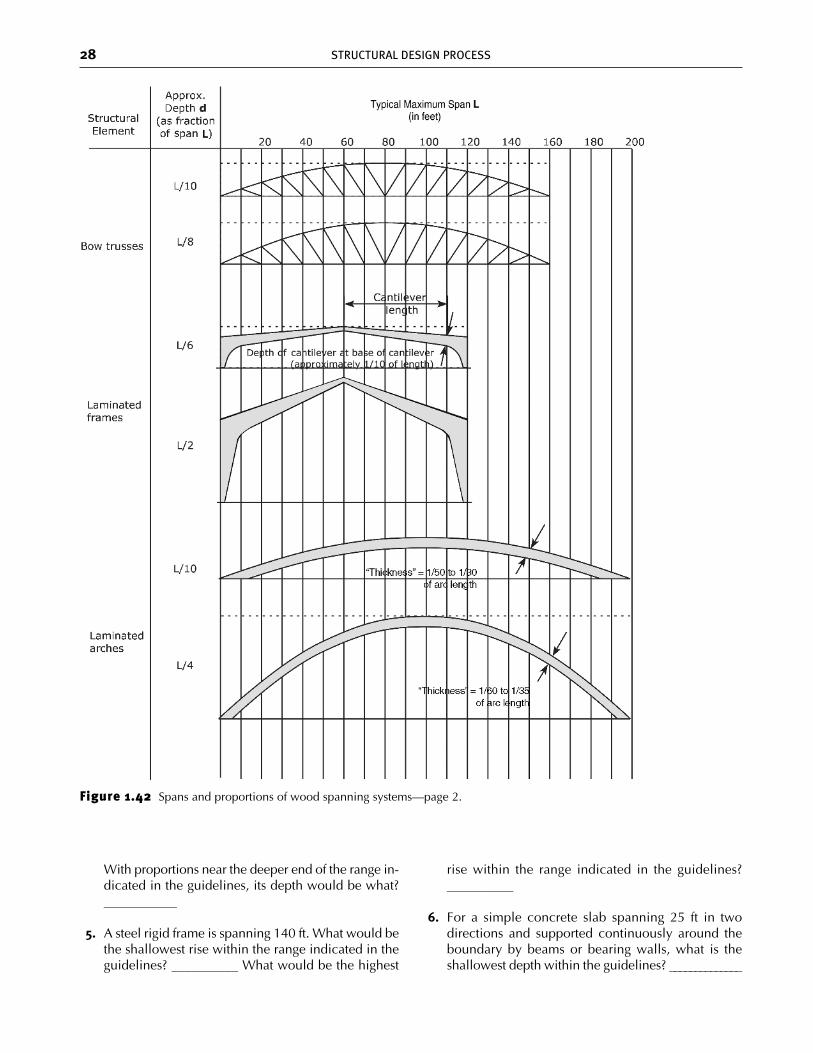
Figure 1.42 Spans and proportions of wood spanning systems—page 2.
With proportions near the deeper end of the range in-dicated in the guidelines, its depth would be what?___________
5. A steel rigid frame is spanning 140 ft. What would bethe shallowest rise within the range indicated in theguidelines? __________ What would be the highest
rise within the range indicated in the guidelines?__________
6. For a simple concrete slab spanning 25 ft in twodirections and supported continuously around theboundary by beams or bearing walls, what is theshallowest depth within the guidelines? ______________
ch01_4643 2/5/07 12:14 PM Page 28
1.7 DESIGN GUIDELINES FOR SPANS AND PROPORTIONS OF COMMON MEMBERS AND SYSTEMS 29
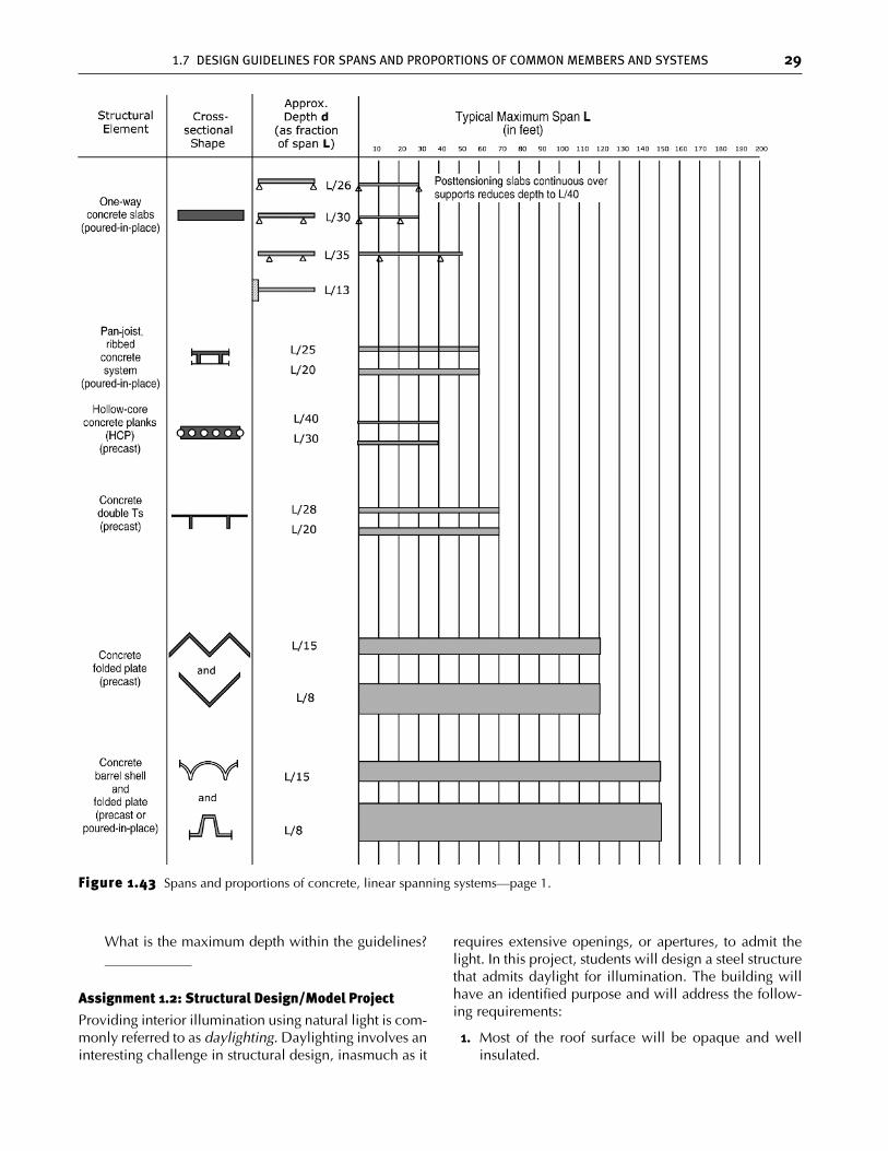
Figure 1.43 Spans and proportions of concrete, linear spanning systems—page 1.
What is the maximum depth within the guidelines?____________
Assignment 1.2: Structural Design/Model Project
Providing interior illumination using natural light is com-monly referred to as daylighting. Daylighting involves aninteresting challenge in structural design, inasmuch as it
requires extensive openings, or apertures, to admit thelight. In this project, students will design a steel structurethat admits daylight for illumination. The building willhave an identified purpose and will address the follow-ing requirements:
1. Most of the roof surface will be opaque and wellinsulated.
ch01_4643 2/5/07 12:14 PM Page 29
30 STRUCTURAL DESIGN PROCESS
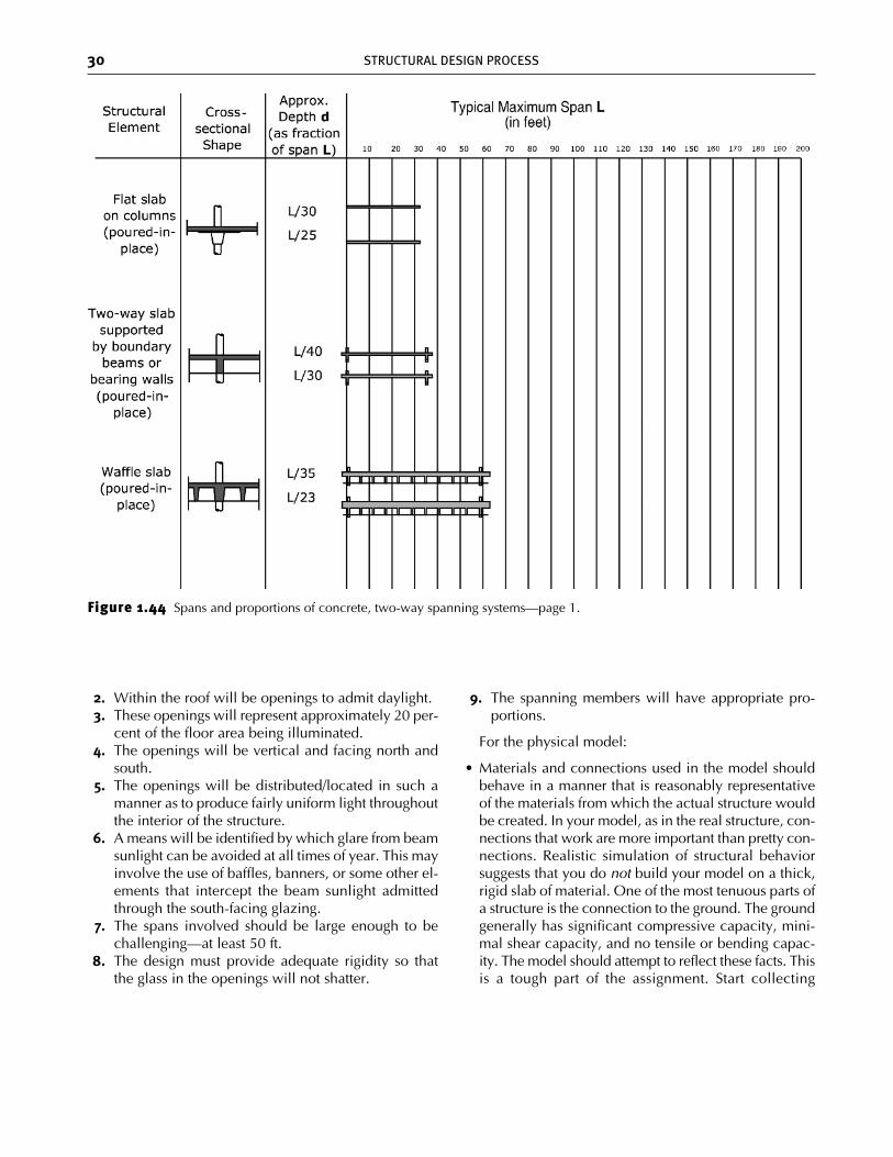
Figure 1.44 Spans and proportions of concrete, two-way spanning systems—page 1.
2. Within the roof will be openings to admit daylight.3. These openings will represent approximately 20 per-
cent of the floor area being illuminated.4. The openings will be vertical and facing north and
south.5. The openings will be distributed/located in such a
manner as to produce fairly uniform light throughoutthe interior of the structure.
6. A means will be identified by which glare from beamsunlight can be avoided at all times of year. This mayinvolve the use of baffles, banners, or some other el-ements that intercept the beam sunlight admittedthrough the south-facing glazing.
7. The spans involved should be large enough to bechallenging—at least 50 ft.
8. The design must provide adequate rigidity so thatthe glass in the openings will not shatter.
9. The spanning members will have appropriate pro-portions.
For the physical model:
• Materials and connections used in the model shouldbehave in a manner that is reasonably representativeof the materials from which the actual structure wouldbe created. In your model, as in the real structure, con-nections that work are more important than pretty con-nections. Realistic simulation of structural behaviorsuggests that you do not build your model on a thick,rigid slab of material. One of the most tenuous parts ofa structure is the connection to the ground. The groundgenerally has significant compressive capacity, mini-mal shear capacity, and no tensile or bending capac-ity. The model should attempt to reflect these facts. Thisis a tough part of the assignment. Start collecting
ch01_4643 2/5/07 12:14 PM Page 30
1.7 DESIGN GUIDELINES FOR SPANS AND PROPORTIONS OF COMMON MEMBERS AND SYSTEMS 31
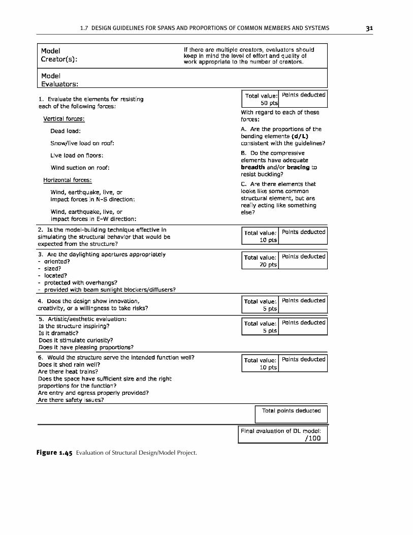
Figure 1.45 Evaluation of Structural Design/Model Project.
ch01_4643 2/5/07 12:14 PM Page 31
32 STRUCTURAL DESIGN PROCESS
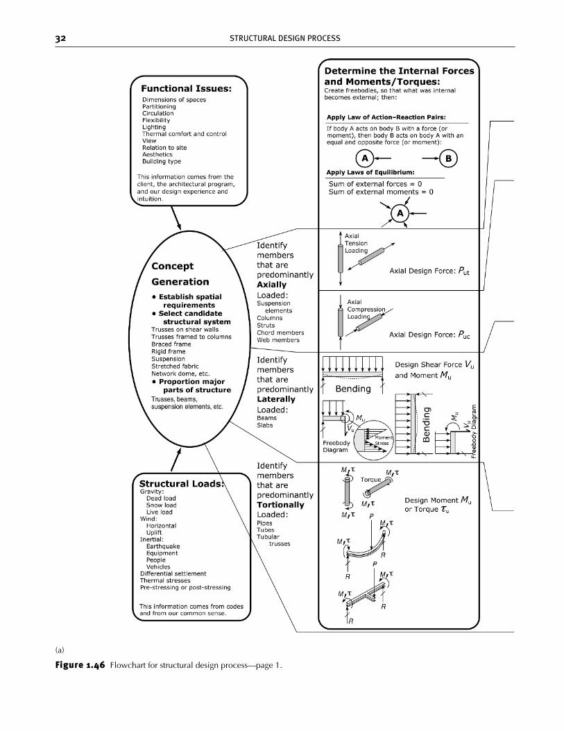
Figure 1.46 Flowchart for structural design process—page 1.
(a)
ch01_4643 2/5/07 12:14 PM Page 32
1.7 DESIGN GUIDELINES FOR SPANS AND PROPORTIONS OF COMMON MEMBERS AND SYSTEMS 33
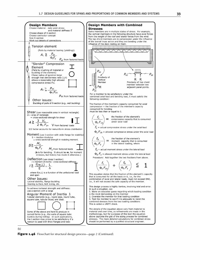
Figure 1.46 Flowchart for structural design process—page 2 (Continued).
(b)
ch01_4643 2/5/07 12:14 PM Page 33
materials early and do experiments to see how best toconnect those materials. Explore how best to expressthe structural behavior of your design.
• A sequence of models in partially completed stateswould be useful if you are exploring a new structuralconcept. In this manner, the structural function of eachpart can be demonstrated as it is added to the structure.If you want to build several good models, group pro-jects will be considered. Discuss your team plan withthe instructor before proceeding. The additional levelof effort needed to justify additional team membersshould be apparent in the project.
• Write a succinct one-page description of the rationalesunderlying your design. This should include a de-scription of which elements bear primary responsibil-ity for each of the common loads that would have tobe addressed, especially gravity and wind in all direc-tions, including wind suction on the roof. See the loadschecklist at the beginning of Chapter 2. Discuss mate-rials, methods of connection, and fabrication and con-struction issues.
• Put a scale figure in the model to indicate its size.
Make your design something that excites you. It shouldrepresent structural beauty, as you define it at this stagein your development as a designer.
Assignment 1.3: Structural Model Analysis/Evaluation
To stimulate active student participation in the discussionand analysis of the structural models, the class will be di-vided into groups. (Three students per group seems to bea manageable size that offers diversity of ideas withoutbeing so large that voices get lost. The instructor willmake the final decision on the size of the groups.) Eachgroup will prepare a detailed (but concise) written analy-sis of four models other than their own.
The student groups will be formed by students signingup together. The sign-up sheet will indicate the methodby which three models will be assigned to each group.In addition to the three assigned models, each group willselect one other model for review. Each group is en-couraged to select a model that is as different as possiblefrom the models that are assigned. If a group has been as-signed a model that is substantially incomplete, the groupis encouraged to choose another model to replace it.
Each group is to choose a location in which to workand to mark that location with a sheet of paper with theletter representing the group (A, B, C, etc.). Then, eachperson in the class is responsible for taking his or hermodel to the location of the group that will be review-ing it.
To bring some structure and discipline to this process,an evaluation sheet has been provided (see Figure 1.45).On the evaluation sheet, various design issues are listed
and point values are assigned. This evaluation sheet willbe the point of departure for all discussions of the mod-els. As you proceed in your discussions, you may wantto make suggestions regarding additional issues thatshould be included on the sheet or for changes in the as-signment of points. It is recommended that you use apencil so that you can edit your work.
When the instructors do the final grading of the mod-els, they will simultaneously grade these reviews. Serious,thoughtful reviews will get high marks.
In each group, all three individuals will participate in allfour reviews. A review should reflect the sentiments of allthe members of the group. Moreover, the grade for allgroup members will be the same, so it is truly a collectiveeffort. To ensure that the work is fairly distributed, eachgroup member should assume responsibility for the actualwrite-up of at least one of the model projects.
Each group member should review all write-ups andprovide editorial comments to the person primarily re-sponsible for the write-up.
One week later, lab time will be allocated for studentsto present their evaluations to the class and to lead classdiscussion of the projects. As you write up the evalua-tions, think about what you consider important to presentto the class. Prioritize the issues for each model. Thesepresentations should not ramble. They must get to key is-sues and should focus on a few key points, such as: “Thisaspect of the design/model is particularly deficient” or“one of the really strong points of this design/model was . . .” Think of your task as being to enlighten your fel-low students—not to fill time.
1.8 Flowchart of the Structural DesignProcess
The flowchart in Figure 1.46 describes the structuraldesign process that is followed in practice. Some of theconcepts outlined here will be fully understood only asthe reader goes through each of the chapters of thisbook. However, the gist of the process should be ap-parent in what is shown. This flowchart will be a kindof road map for the process. As you learn new things,you will periodically return to this road map to help youknow where you stand in learning about the process. Atthis first encounter with the road map, you are encour-aged to study it and try to understand its salient features.Even though its details will in some ways exceed yourunderstanding at first encounter, it is still worth begin-ning the process of getting the map in your head. Oth-erwise, there will be a tendency to see each chapter ofthis book as isolated and episodic, rather than as part ofa coherent process.
34 STRUCTURAL DESIGN PROCESS
ch01_4643 2/5/07 12:14 PM Page 34