Embed Size (px)
DESCRIPTION
Structural Integrity of Hybrid Metal Composite Structures in a Fighter Aircraft. Presented at Flygteknik 2010 – Stockholm, October 18-19, 2010. NFFP – Structural Assessment of Hybrid Structures - PowerPoint PPT Presentation
Citation preview

Structural Integrity of Hybrid Metal Composite Structures in a Fighter Aircraft
Presented at Flygteknik 2010 – Stockholm, October 18-19, 2010

NFFP – Structural Assessment of Hybrid Structures
Research programme aiming to develop the required methodology and data to certify complex metal/composite hybrid assemblages subjected to in-flight coupled thermo-mechanical load spectra.
Focused on test verification techniques to cover the significant effects of:
Thermal induced stresses - dissimilar thermal expansion - heat transfer into structure - speed & altitude - surrounding temperature
Load sequences - rare high peak loads - frequent small load ranges

Wing – Fuselage Attachment
A/B/C/D - versions
E/F - versions

Full-scale fatigue test of complete airframeand sub assemblages

xyFlight
yFlight y
Temp
P low LT
yFlight
xTemp
xyFlight
P high LT
Coupled thermo-mechanicalload cases

Typical temperatures (MIL-STD-1530C)
Gripen E/F – temperatures for static loads
Sustained – through all structure: -40oC +94oC
85oC 100oC
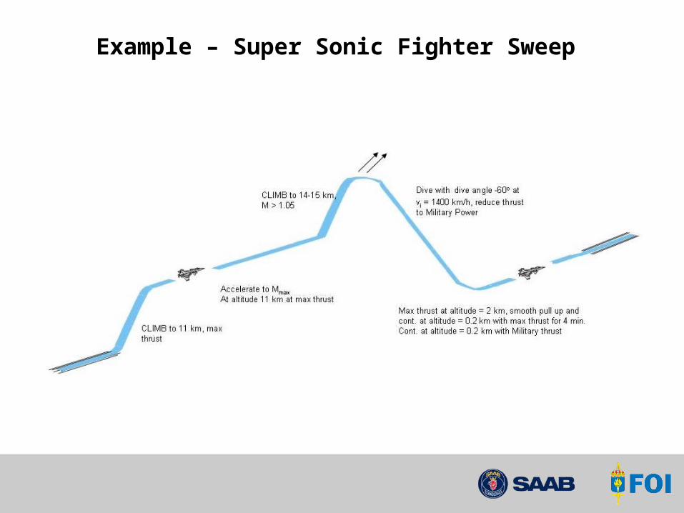
Example – Super Sonic Fighter Sweep

2
0 211 MTT
yFlight
xTemp
xyFlight
P LT
Flight and temperature loads
Heattransfer
StagnationTemperature To

Detailed FE-analysis of complete wing

156
2032
20
228
1632
64
156
D= 8
10Aluminium
9,4 9,4
2 x composite
2032
16
36
160
70
3650 22
8
232
D = 8
Fatigue testing of specimens exposed to heating

Dissimilar failure mechanisms – metal / compositeLoad sequence effects – retardation / accelerations
1E-7
1E-6
1E-5
1E-4
0.001
0.01
0.1
0.01 0.1 1 10 100
Energy Release Rate Range GI (N/mm)
Cra
ck/D
elam
inat
ion
Gro
wth
Rat
e (m
m/c
ycle
)
CFRP IM7/8552Layup 24/24-0-0Interface 0/0
Al-Alloy 7475-T761
R = 0.05
Sheet, t = 2 mmOrientation L-T
Metal predominating singel crack
Composites matrix cracking delamination fiber breakage interfacial debonding

Truncation or extension of high loads
composites (to verify life also for aircraft exposed to rare high loads)
composites
metals
metals (to verify life also for aircraft not exposed to rare high loads)
Elimination of insignificantload cycles
Fatigue test verification of metal and composite structure
Mean maneuver load spectra forone service life e.g. 8,000 hrs.
Load
rang
es
Log number of cycles

Zlatan KapidzikLars DjärvMartin EkströmHans EllströmJonas WahlbäckHans Ansell
Joakim SchönRolf JarlåsAnders BlomBörje Andersson
Participants – NFFP project