Embed Size (px)
Citation preview

Structural Investigation of Historic Buildings
ffirs.indd iffirs.indd i 12/18/08 10:26:01 PM12/18/08 10:26:01 PM
Structural Investigation of Historic Buildings: A Case Study Guide to Preservation Technology for Buildings,Bridges, Towers, and Mills. David. C. Fischetti © 2009 John Wiley & Sons, Inc.

Structural Investigation of
Historic BuildingsA Case Study Guide to Preservation Technology for Buildings, Bridges,
Towers, and Mills
David C. Fischetti
John Wiley & Sons, Inc.
ffirs.indd iiiffirs.indd iii 12/18/08 10:26:02 PM12/18/08 10:26:02 PM

This book is printed on acid-free paper. �
Copyright © 2009 by John Wiley & Sons, Inc. All rights reserved.Published by John Wiley & Sons, Inc., Hoboken, New JerseyPublished simultaneously in Canada
No part of this publication may be reproduced, stored in a retrieval system, or transmitted in any form or by any means, electronic, mechanical, photocopying, recording, scanning, or otherwise, except as permitted under Section 107 or 108 of the 1976 United States Copyright Act, without either the prior written permission of the Publisher, or authorization through payment of the appropriate per-copy fee to the Copyright Clearance Center, 222 Rosewood Drive, Danvers, MA 01923, (978) 750-8400, fax (978) 646-8600, or on the web at www.copyright.com. Requests to the Publisher for permission should be addressed to the Permissions Department, John Wiley & Sons, Inc., 111 River Street, Hoboken, NJ 07030, (201) 748-6011, fax (201) 748-6008, or online at www.wiley.com/go/permissions.
Limit of Liability/Disclaimer of Warranty: While the publisher and the author have used their best efforts in preparing this book, they make no representations or warranties with respect to the accuracy or completeness of the contents of this book and specifi cally disclaim any implied warranties of merchantability or fi tness for a particular purpose. No warranty may be created or extended by sales representatives or written sales materials. The advice and strategies contained herein may not be suitable for your situation. You should consult with a professional where appropriate. Neither the publisher nor the author shall be liable for any loss of profi t or any other commercial damages, including but not limited to special, incidental, consequential, or other damages.
For general information about our other products and services, please contact our Customer Care Department within the United States at (800) 762-2974, outside the United States at (317) 572-3993 or fax (317) 572-4002.
Wiley also publishes its books in a variety of electronic formats. Some content that appears in print may not be available in electronic books. For more information about Wiley products, visit our web site at www.wiley.com.
Library of Congress Cataloging-in-Publication Data:
Fischetti, David C. Structural investigation of historic buildings : a case study guide to preservation technology for buildings, bridges, towers, and mills / David C. Fischetti. p. cm. Includes index. ISBN 978-0-470-18967-2 (cloth) 1. Building inspection. 2. Historic buildings—Conservation and restoration—Case studies. 3. Historic preservation—Conservation and restoration— Case studies. 4. Structural engineering—United States. I. Title. TH439.F55 2008 720.28'8—dc22
2008038581
Printed in the United States of America10 9 8 7 6 5 4 3 2 1
ffirs.indd ivffirs.indd iv 12/18/08 10:26:03 PM12/18/08 10:26:03 PM

v
Contents
Introduction vii
Acknowledgments x
CHAPTER 1 Historic Structures: The Role of the Structural Engineer 1
CHAPTER 2 Preservation and Public Safety: Structural Safety of Historic Timber Structures 15
CHAPTER 3 Simplifi ed Engineering 21
CHAPTER 4 Conservation and the Specialty Contractor 41
CHAPTER 5 Historic Timber Structures 57
CHAPTER 6 Watauga Hall and the Montague Building 71
CHAPTER 7 The Restoration of St. Helena’s Church 91
CHAPTER 8 Market Hall Rehabilitation 115
CHAPTER 9 Differential Settlement at St. Philip’s Moravian Church at Old Salem 123
CHAPTER 10 James Madison’s Montpelier 139
CHAPTER 11 Timber, Glulam, and Conservation 149
ftoc.indd vftoc.indd v 12/18/08 10:25:42 PM12/18/08 10:25:42 PM

vi Contents
CHAPTER 12 Tabby: Engineering Characteristics of a Vernacular Construction Material 169
CHAPTER 13 Relocating the Cape Hatteras Lighthouse 181
CHAPTER 14 Crisis in American Covered Bridges 207
CHAPTER 15 The Timber Trusses of Burr, Town, and Haupt 211
CHAPTER 16 The Cornish-Windsor Covered Bridge 227
CHAPTER 17 A New Covered Bridge for Old Salem 241
CHAPTER 18 The Tohickon Aqueduct 253
CHAPTER 19 The Current State of Historic Preservation Engineering: One Engineer’s Point of View 263
Index 271
ftoc.indd viftoc.indd vi 12/18/08 10:25:43 PM12/18/08 10:25:43 PM

Introduction
I In North America, our built environment of what is commonly referred to as historic structures typically includes everything 50 years of age or older. These
structures are as diverse as Montezuma Castle, a cliff dwelling of mud and stone constructed in Arizona about 1150 A.D., to Dorton Arena, the world ’ s fi rst cable - supported roof system, built in Raleigh, North Carolina, in 1952.
The purpose of this book is to help prepare consulting structural engineers and others to deal with issues unique to historic structures. This book will also explore the reasons why engineering practitioners tend to shy away from these projects. Unfortunately, for liability concerns, and other reasons, few American structural engineers have embraced a preservation philosophy that allows for the continued use of our architectural and structural heritage. And yet, with the possible exception of the absence of timber design in some programs, civil engineering curricula in most North American universities should adequately equip the graduate engineer with suffi cient skills to address the varied chal-lenges posed by evaluation and condition assessment through observation, measurement, analysis, and testing.
The case studies in this book are not totally representative of the full array of possible building types that may be encountered by the great majority of structural engineers. As case studies, they represent the particular experience encountered in one consulting structural engineer ’ s practice. The building types may be somewhat skewed by my experience in timber design and my geographic location, and specifi cally, the states where I am registered to prac-tice engineering.
This book can serve as a text in preservation courses for students of many disciplines. Whether the curriculum is history, architecture, art history, plan-ning, engineering, construction management, or materials based, there is a need for the students who are anticipating a preservation career to know what to expect from their structural engineer team members or consultants. The seasoned structural engineer will fi nd information useful to projects involving existing buildings to the extent that one may wish to obtain continuing educa-tion credits in the fi eld to fulfi ll registration obligations, or obtain some certifi -cate or advanced degree in historic preservation.
vii
flast.indd viiflast.indd vii 12/18/08 10:25:25 PM12/18/08 10:25:25 PM

viii Introduction
Conservation of our existing structures has obvious economic and social value. The success of various structural engineering solutions can be told through case studies to a wider audience, so that potential candidates for res-toration, rehabilitation, or adaptive reuse, do not meet the wrecking ball with-out a second chance.
EVALUATING A TIMBER STRUCTURE
Our procedure for evaluating an existing framed building or roof structure, historic or not, is to apply today ’ s code mandated snow, live, and wind and seismic loads to various component systems, assuming that no deterioration has occurred. In this way, the original structure can be tested with specifi c load criteria, against reasonable allowable design values so that the amount of stress in various elements can be tabulated and compared to allowables.
By performing a computer analysis, the stiffness in various components, and the continuity, or lack of continuity, through joints, can be included, resulting in accurate theoretical defl ections. The computed defl ections can then be compared to today ’ s code mandated limits for structures. Once this process is completed, then a review of the amount of stress in particular elements can be compared against reasonable values that could be expected from the materials used at the time the building was constructed. After structural analysis is complete, then a condition analysis can be made on the basis of fi eld observation, measurement, and testing. Ideally, it is best to have at least a preliminary analysis in hand prior to actually observing conditions in the fi eld. In reality, we often are responding to the client ’ s wishes to inspect the structure as soon as possible, without benefi t of measured drawings from the architect or prior information of any kind.
Through analysis and engineering judgment, the capacity of various compo-nents can be tabulated to account for deterioration. The theoretical defl ection can be compared to the actual deformation of the structure as measured in the fi eld.
Each study will be presented with emphasis on the structural evaluation and condition assessment. Each section will include a description of the project and its history, a condition assessment, structural analysis, discussion, recommendations and a description of the subsequent intervention as executed with drawings and photographs.
WHY THE BOOK IS NEEDED
Tasks as simple as determining the grades and applicable design values for tim-ber components and how to apply the effects of load duration to the evaluation of historic timber structures need to be included in a preservation engineering
flast.indd viiiflast.indd viii 12/18/08 10:25:26 PM12/18/08 10:25:26 PM

Introduction ix
text. Reservations in the evaluation of wrought iron, and the unknowns associ-ated with determining the capacity of unreinforced historic masonry or archaic concrete systems, are but a few of the issues leading to the wholesale destruc-tion of potentially serviceable buildings and bridges. For example, not knowing the effects on strength of slag inclusions in wrought iron has caused structural engineers to automatically call for the replacement, with new steel, of all the possibly perfectly serviceable wrought iron tension rods in many building trusses and historic bridges.
This book will also raise some questions that will be of interest to the research community. Historic structures provide an excellent laboratory to study aspects of structural engineering, materials science, forensic engineering, and building design.
This book emphasizes a preservation philosophy that stresses achieving structural safety using traditional materials, based on modern analysis, meas-urement, and testing techniques. It is not a compilation of available ASTM tests or a documentation of various archaic structural systems. Lessons learned in historic preservation make us better designers of new structures.
flast.indd ixflast.indd ix 12/18/08 10:25:27 PM12/18/08 10:25:27 PM

Acknowledgments
My career has been infl uenced by many people who do not appear in these case histories who need to be acknowledged. Some, such as Wm. C. Vick
and Tommy Vick of Wm. C. Vick Construction Co. in Raleigh, NC afforded me the opportunity to work on projects with some of these same design issues. Robert C. Browning, P.E. was an engineer interested, early on, on the work I was doing.
My parents Rose and Constantine Fischetti, of course, encouraged me in my career. My grandfather Luigi Rinaldi, Master Brickmason, gave me my fi rst job in construction. I graduated from Brooklyn Technical High School thirty years after my father. The teachers at Brooklyn Tech, most with industrial or construction experience, had a positive infl uence, particularly Angelo Amatelli, Head of the Structural Course of study. My timber design experience began at Koppers Company, Inc. in Pittsburgh in the Unit Structures Department of the Forest Products Division. I would like to thank Harry C. Smith, P.E. and Einar Orsett, P.E. for their guidance.
Over the years many people have typed the various manuscripts which enabled this book to be published: Denise Bowles, Beckie Mitchem, Dolly Foster, Lynn McBride, Tami Wahl, and Connie Harrison. Most important is Gretchen Moog Tippett whose work was crucial in the fi nal production of the manuscript. I want to also acknowledge Jim Harper, my editor, and Nancy Cintron, production editor, at Wiley.
This book would not be possible without the work of my daughter Stephanie A. Fischetti who assembled the initial outline and proposal.
Most of all I would like to thank my wife Joyce and our family for all of their love and support.
x
flast.indd xflast.indd x 12/18/08 10:25:27 PM12/18/08 10:25:27 PM

FIGURE 6-7 Floors were replaced in the Eagle Block (ca. 1835) in similar fashion to Watauga Hall. (See page 87 for discussion.)
FIGURE 7-10 Lateral bracing consisting of timber poles and framing was installed on both side-walls. (See Chapter 7 for discussion of St. Helena’s Church.)
bins.indd 1bins.indd 1 12/18/08 3:44:32 PM12/18/08 3:44:32 PM
Structural Investigation of Historic Buildings: A Case Study Guide to Preservation Technology for Buildings,Bridges, Towers, and Mills. David. C. Fischetti © 2009 John Wiley & Sons, Inc.

FIGURE 7-19 All exterior surfaces were renewed, including the steeple. (See Chapter 7 for dis-cussion of St. Helena’s Church.)
FIGURE 8-4 The technology used is common to the timber period of original construction. (See Chapter 8 for discus-sion of Market Hall.)
bins.indd 2bins.indd 2 12/18/08 3:44:40 PM12/18/08 3:44:40 PM

FIGURE 8-5 The iron work was restored to its original confi guration and color. (See Chapter 8 for discussion of Market Hall.)
FIGURE 8-6 This completed building again houses the Confederate Museum. (See Chapter 8 for discussion of Market Hall.)
bins.indd 3bins.indd 3 12/18/08 3:44:48 PM12/18/08 3:44:48 PM

FIGURE 9-5 The log church has a false chimney and cupola. (See pages 131 to 134 for discussion of the St. Philip’s Log Church.)
FIGURE 10-1 View of the surrounding property from the attic. (See Chapter 10 for discussion of James Madison’s Montpelier.)
FIGURE 9-16 The masonry wall was supported by the mini-piles. Steel bands were used to provide under-slung support to the wall. (See Chapter 9 for discussion of St. Philip’s Church.)
bins.indd 4bins.indd 4 12/18/08 3:44:54 PM12/18/08 3:44:54 PM

FIGURE 10-10 Arnold Graton (shown here) temporarily braced the chimney prior to removing soil and installing jacks. (See Chapter 10 for discussion of Montpelier.)
FIGURE 10-12 The chimney extension provided duct access into the vertical spaces within the chimney. (See Chapter 10 for discussion of Montpelier.)
FIGURE 12-7 The Horton-DuBignon House on Jekyll Island (ca. 1738) is one of the oldest tabby structures in Georgia. (See Chapter 12 for discussion on Tabby.)
bins.indd 5bins.indd 5 12/18/08 3:45:09 PM12/18/08 3:45:09 PM

FIGURE 15-3 The deteriorated members in the Utica Road Covered Bridge were replaced in kind. (See page 213 for discussion.)
FIGURE 15-4 The Old Salem Covered Bridge is a modifi ed Burr. A partial arch is shown here during construction. (See Chapter 17 for discussion.)
FIGURE 15-8 The Bunker Hill Covered Bridge with repairs almost completed. (See pages 219–225 for discussion.)
bins.indd 6bins.indd 6 12/18/08 3:45:28 PM12/18/08 3:45:28 PM

FIGURE 16-3 The cable stayed system allowed for an orderly rehabilitation of the roof structure. (See Chapter 16 for discussion of the Cornish-Windsor Bridge.)
FIGURE 16-8 The governors of both New Hampshire and Vermont attended the dedication ceremony. (See Chapter 16 for discussion of the Cornish-Windsor Bridge.)
FIGURE 17-1 The acrylic panels provided a weathertight sidewall closure. (See Chapter 17 for discussion of the Old Salem Covered Bridge.)
bins.indd 7bins.indd 7 12/18/08 3:45:38 PM12/18/08 3:45:38 PM

FIGURE 18-1 The aqueduct consists of three equal spans of 66 feet. (See Chapter 18 for discussion of the Tohickon Aqueduct.)
FIGURE 18-7 The completed aqueduct won a National Timber Bridge Award in 2002. (See Chapter 18 for discussion of the Tohickon Aqueduct.)
bins.indd 8bins.indd 8 12/18/08 3:45:48 PM12/18/08 3:45:48 PM

1
C H A P T E R 1 Historic Structures: The Role of the Structural Engineer
THE STRUCTURAL ENGINEER AS A PRESERVATIONIST
S Services of the structural engineer may include planning, estimating, mak-ing structural evaluations, conducting feasibility studies, designing, and
consulting. Adaptive use, the practice of renovating or rehabilitating a struc-ture for a use other than that for which it was fi rst designed, involves, for the structural engineer, several opportunities to be of service. Although the fi nal construction cost may include as little as 5 to 12 percent of the total project cost for structural work, the structural engineer may play a pivotal role in determining whether a project will be economically feasible. A structural eval-uation will indicate whether structural elements are reused, reinforced, or replaced.
Often, adapting a building to a new use requires extensive structural changes to be made in order to make the building conform to current needs and code requirements. A common challenge for the structural engineer is how to construct, within a historic structure, an elevator shaft so that upper fl oors may be accessible. Seismic retrofi t is an important concern facing historic structures in areas where retroactive seismic building code requirements are in force. The services provided by a structural engineer associated with moving a
c01.indd 1c01.indd 1 12/18/08 10:06:12 PM12/18/08 10:06:12 PM
Structural Investigation of Historic Buildings: A Case Study Guide to Preservation Technology for Buildings,Bridges, Towers, and Mills. David. C. Fischetti © 2009 John Wiley & Sons, Inc.

historic building might include a structural evaluation to determine whether the structure can be moved intact, partially disassembled, or relocated in sec-tions. Structural reinforcement or the design of a new foundation might also be required. Registered land surveyors are the most qualifi ed to provide accurate base measurements when the extensive documentation of a historic structure is required.
REHABILITATION GUIDELINES
All structural engineers should obtain a copy of The Secretary of the Interior ’ s Standards for Rehabilitation . Under these standards, rehabilitation means “ the process of returning a property to a state of utility, through repair or alteration, which makes possible an effi cient contemporary use while preserving those portions and features of the property that are signifi cant to its historic, archi-tectural, and cultural value. ” Minimum alteration of the building, its environ-ment, and its distinguishing architectural qualities is required for a project to qualify as a “ certifi ed rehabilitation ” benefi ting from the provisions of the tax act. Archeological resources must be protected, as well as signifi cant historical, architectural, or cultural material. An understanding of the historical signifi -cance of a building must be obtained to enable the engineer to provide an acceptable solution to a particular design problem while following the “ secre-tary ’ s standards. ”
The guidelines for applying The Secretary of the Interior ’ s Standards for Rehabilitation recommend recognition of the “ special problems inherent in the structural system of historic buildings, especially where there are visible signs of cracking, defl ection, or failure. ” In addition, “ stabilization and repair of weakened structural members and systems when damaged or inadequate ” are recommended. “ Historically important structural members ” are to be replaced “ only when necessary. ” 1
BUILDING CODES AND HISTORIC STRUCTURES
The structural engineer must make a realistic judgment when applying modern building code live - load requirements to a historic structure. For example, how much snow can adhere to a steeply pitched slate or tin roof? How does one rationalize the successful service of a hundred - year - old church roof struc-ture when the forces obtained from the frame analysis appear too great for the
2 Historic Structures: The Role of the Structural Engineer
c01.indd 2c01.indd 2 12/18/08 10:06:13 PM12/18/08 10:06:13 PM

connections involved? As in the review and evaluation of any structure, the engineer must make a judgment, based on available information, of the safety of such a structure. Should the engineer call for the reinforcing of a timber fl oor structure with steel beams when it is safe in bending and shear but exceeds defl ection requirements when loaded with a required minimum live - load based on occupancy?
The 2006 North Carolina State Building Code, which is the Standard Building Code with North Carolina amendments, includes several provisions for historic structures. In Section 1009, “ Historic Buildings for Public Display or Exhibition ” and Section 1010, “ Historic Buildings for Adaptive Use, ” the defi nition of historic buildings is as follows:
General (a) Historic buildings means buildings designated as historic properties. (1) By the state historic preservation offi cer acting on behalf of the North
Carolinian Historical Commission in accordance with the provisions of G.S. 121.8 and NCAC 46.0600.
(2) Or by a local historic properties commission constituted in accordance with G.S. 160A.399.2 subject to review and approval by the Building Code Council. 2
Included in the code are provisions regarding repairs, additions, sprinkler systems, means of egress, and the moving of historic buildings.
In recent years several codes have adopted the innovations and principles of the New Jersey Rehabilitation Subcode commonly know as the New Jersey Rehab Code which was fi rst published in 1997. Chapter 34, Existing Struc-tures in the 2003 International Building Code also includes Section 3407 enti-tled Historic Buildings states that, “ The provisions of this code relating to the construction, repair, alteration, addition, restoration, and movement of struc-tures, and change of occupancy shall not be mandatory for historic buildings where such buildings are judged by the building offi cial to not constitute a distinct life safety hazard. ” 2
THE STRUCTURAL EVALUATION
Structural engineers have been reluctant to become involved with historic preservation projects, often because of the potential liability imposed on the engineer. By merely providing a structural evaluation of a historic structure, the engineer may become “ the engineer of record ” for a building constructed
The Structural Evaluation 3
c01.indd 3c01.indd 3 12/18/08 10:06:14 PM12/18/08 10:06:14 PM

with “ primitive ” methods and materials. Many historic structures were not rigorously analyzed, but proportioned by the eye of an experienced builder or simply built as was the custom.
If the engineer becomes involved in even a small portion of a historic pres-ervation project, there must be adequate compensation for the assumed liabil-ity. The engineer must be completely satisfi ed that a structure meets the loading requirements for its intended occupancy, as well as all external forces.
Structural evaluations usually include a determination of the ability of a fl oor or roof system to support these service loads. An existing structure might have to be monitored in order to obtain data for such an evaluation. Testing programs may have to be designed to aid in determining the strength of com-ponent materials or complete assemblies. Methods may consist of destructive or nondestructive testing of component materials or load tests of structural members such as beams or assemblies such as trusses. It will likely be neces-sary to adapt current testing methods for fi eld use on historic structures.
Accurate fi eld measurements are essential in defi ning the structure and its condition. Surveying methods have been successfully utilized in determining the stiffness of defl ected beams and trusses. A topographic plan of the fl oor surface of a historic structure will yield a useful visual representation of an irregular fl oor if the contour interval is small. Irregular fl oors in a historic structure could be caused by movement in the supporting soils, timber decay or shrinkage, or defl ection of structural components. The ability to interpret the response of a structure to background vibrations and induced vibrations has made vibratory testing a valuable historic preservation tool. X - ray, liquid penetrant, nuclear particle density meters, and ultrasonic techniques are being used to evaluate various construction materials.
The correct interpretation of masonry cracks may yield accurate informa-tion regarding the location and amounts of settlement or thermal movement. Monitoring such cracks is possible with “ telltales ” such as glass slides epoxied to the wall surface on each side of a fi ssure. Even slight movement can be detected by using such a strategy. Accurate monitoring of cracks is possible with calibrated telltales accurate to within one millimeter and electronic strain gauges.
Load testing a historic structure may be the only reasonable way to justify conditions or materials that are diffi cult to analyze. In designing a load test, the engineer must call for the application of realistic loads carefully applied.
Great care should be taken before applying twice the design live load, as required by many building codes, to a historic structure. For timber structures it may be unrealistic to apply full live load plus an increase for a period such as 24 or 48 hours, when the structure actually will never reach that service loading for
4 Historic Structures: The Role of the Structural Engineer
c01.indd 4c01.indd 4 12/18/08 10:06:14 PM12/18/08 10:06:14 PM

that length of time. Applying a known, safe load to a historic structure is an excellent method for determining the stiffness characteristics of various materi-als. This is of special value when evaluating timber structures. It is important to realize that because of the variation in the strength characteristics of timber, a load test of one member of a structure may not be indicative of the true capacity in other areas of the building.
For any material, before a load test is undertaken, the engineer must be cer-tain that all lateral bracing and slenderness requirements are satisfi ed. A prelimi-nary analysis must be performed to ensure that the structure will not be loaded past the elastic limit or further to destruction. The application of strain gages and other instrumentation is highly desirable in monitoring a load test. Through the use of monitoring techniques, testing, measurements, observation, and structural calculations, an accurate interpretation of the structural capability of a historic structure can be presented in a carefully written report.
MATERIALS RESEARCH
Research may yield information useful in the evaluation, rehabilitation, or ren-ovation of the historic structure. Original plans, construction photographs, and written or oral accounts may provide clues to the original design or con-struction methodology. Old textbooks or materials handbooks may provide design methods and design strengths of various materials.
FIGURE 1-1 This load test utilized water to determine the average stiffness of a series of recycled joists.
Materials Research 5
c01.indd 5c01.indd 5 12/18/08 10:06:14 PM12/18/08 10:06:14 PM

The structural engineer must be familiar with the properties of materials such as timber, steel, cast iron, wrought iron, stone, brick masonry, terra cotta, and reinforced concrete. Patented fl oor or roof systems composed of various materials might appear only in manufacturer ’ s literature, with little or no design information available.
THE EVALUATION OF CONCRETE
Reinforcing steel in older concrete buildings may be square, round, or hexago-nal in cross - section with various types of deformations and exhibiting various physical properties. Early reinforcing steel was produced as plain and deformed steel in structural, intermediate, and hard grades. Structural grade was nor-mally used unless specifi ed otherwise. Structural engineers should obtain a copy of CRSI Engineering Data Report, no. 11, titled “ Evaluation of Reinforc-ing Steel in Old Reinforced Concrete Structures. ” 3
The fi rst specifi cations for reinforcing steel were developed in 1910 by the Association of American Steel Manufacturers. In 1911, the American Society for Testing and Materials adopted standard specifi cation A15 for billet steel concrete reinforcing bars. Minimum working stresses and yield strengths for these and other early specifi cations are presented in the CRSI report.
The most diffi cult problem in evaluating historic reinforced concrete struc-tures is determining the size and location of the reinforcing steel. Various instru-ments now available may be used for such purposes, but should be verifi ed by exposing the reinforcing steel in noncritical locations to visual inspection.
Development lengths, bending and cutoff details, and effective depths must be determined. The material properties of both the steel and concrete should be determined by testing. Samples of reinforcing steel suitable for test-ing can usually be obtained without affecting the structural adequacy of an existing structure if the locations are carefully selected. A preliminary struc-tural analysis aids in locating areas of low stress suitable for sampling. Nonde-structive load testing of complete fl exural members can be employed to verify calculated defl ections. Accurate methods are still needed to aid engineers in evaluating the effects of voids, cracks, and deteriorated reinforcing.
BRICK MASONRY RESTORATION
Lime - sand mortar, commonly used in structures located above water level, is of great importance in the repair and restoration of historic buildings. The structural engineer interested in historic preservation should be familiar with masonry restoration specifi cations.
6 Historic Structures: The Role of the Structural Engineer
c01.indd 6c01.indd 6 12/18/08 10:06:15 PM12/18/08 10:06:15 PM

Mortar for face brick should match the original mortar in color, texture, density, and porosity. It should have strength equal or less than that of the original mortar. New mortar should have hardness equal to or less than that of the original brick, as determined by testing. The color of mortar used for repointing should be matched to the original by matching the color of original aggregates and mortar components as closely as possible. An archeological search may uncover ingredients of the original job mixed mortar, such as oyster shells, in the soil strata at the site in the builder ’ s trench, which contains other construction debris.
The density and strength of historic brick units are a function of their position in the kiln and how well they were fi red. Salmon brick, which are lightly burned, were typically reserved for the center of a wall and the harder, better burned, brick used as exterior face brick. Because of the extreme vari-ations in their strength and durability, the use of salvaged brick should be discouraged.
There are manufacturers who can match old brick very accurately and several manufacturers who are making bricks by the old methods. These bricks and a compatible lime mortar design mix are what is required to match the brick masonry of historic buildings. Repointing brick masonry is a waterproof-ing procedure and not a solution for structural problems. The repointing process is a critical procedure that should be done in carefully selected areas with great care. 4
Materials engineers should become familiar with the components of his-toric mortars, and in that light review the methods for sampling and testing of masonry. The Brick Institute of America, Technical Notes on Brick Construc-tion , no. 39A, reviews procedures for testing brick prisms. 5 The standard ASTM methods of tests for masonry assemblages are especially applicable to the testing of historic masonry because of the possible variation in the mortar and brick strengths. The performance of historic mortar and brick can be eval-uated in this way, not as individual components, but as they would perform together in the wall. Of course, obtaining suitable undisturbed samples for testing can be a problem with fragile materials.
Once a replacement brick is selected and the original mortar approxi-mated, prism testing of replacement masonry should yield information regard-ing allowable stresses that may be used in design. Mortar analysis and mix design should be accompanied by strength tests that can be evaluated by a materials testing engineer. There has been a tendency in the fi eld of historic preservation to select brick and mortar so that they merely “ look ” right when placed alongside original masonry. The structural engineer can best determine that strength characteristics of replacement masonry materials are as compatible as the color and texture.
Brick Masonry Restoration 7
c01.indd 7c01.indd 7 12/18/08 10:06:16 PM12/18/08 10:06:16 PM

The use of grinders, sandblasting, sanding discs, or other abrasives normally are not permitted in the cleaning of brick. Irrevocable damage has been done to historic masonry by abrasive cleaning. For example, removal of the outer surface of old brick may expose the more porous inner portion of the brick, which may lead to spalling due to moisture penetration and subsequent freezing.
TIMBER DESIGN AND HISTORIC PRESERVATION
Often, the proper analysis and evaluation of a historic structure requires that the structural engineer have extensive timber design experience. Many historic structures in the United States are timber framed. Masonry construction is generally used for foundations, exterior wall support, and building enclosure. A thorough knowledge of the physical and mechanical properties of wood is necessary.
Many historic structures were constructed of green timber because of the considerable time required to air dry large timbers. In the seasoning process, timber gives off or takes on moisture from the surrounding atmosphere with changes in temperature and relative humidity until it attains a balance relative to the atmospheric conditions. Historic structures have had time to reach this point of balance, known as the equilibrium moisture content.
FIGURE 1-2 The entrance gates for Camden (Railroad) Yards in Charleston, South Carolina, were restored and the stucco was renewed.
8 Historic Structures: The Role of the Structural Engineer
c01.indd 8c01.indd 8 12/18/08 10:06:16 PM12/18/08 10:06:16 PM

Moisture content is the weight of the water contained in wood, expressed as a percentage of the weight of the oven - dried wood. As wood loses moisture, the water in the cell cavity evaporates fi rst. The condition at which the water in the cell cavity has been evaporated but the cell wall is still saturated is known as the “ fi ber saturation point. ” This point is usually assumed to be at approximately 30 percent. When the moisture content is reduced below this point, shrinkage will occur. 6
Builders of heavy timber structures usually made allowances for shrinkage in the design of members and connections. The amount of shrinkage may be calculated using tables that give amounts of radial, tangential, and volumetric shrinkage from green to the oven oven - dried moisture content for various spe-cies. A moisture meter is an important tool for the structural engineer. What has been misinterpreted as defl ection or settlement in historic structures may be due to the across - the - grain shrinkage of large timber girders that were installed in a green condition and subsequently dried to low moisture content.
An increment borer can be used by the structural engineer to obtain core samples 0.2 of an inch in diameter, which can be used to determine the species, the number of growth rings per inch, the oven - dried weight, the moisture con-tent, and the specifi c gravity of the wood sampled.
Often, certain parts of a structure will indicate a moisture content that is considerably higher than the equilibrium moisture content determined by the dry bulb temperature and relative humidity. Usually, close contact of timber with moisture - containing masonry or earth will cause elevated moisture con-tent at the bearing points of timber purlins, joists, beams, columns, or trusses. The moisture is most readily absorbed through end grain. Once the moisture content rises above 20 percent, decay will probably occur. Strength - reducing effects of decay and termite infestation commonly occur at support points. Repairing these areas of high shear is a challenge to the structural engineer involved in historic preservation.
The structural engineer evaluating the heavy timber frame of a historic structure should be intimately familiar with the causes and signifi cance of checking and the structural considerations.
The structural engineer evaluating a timber structure should become famil-iar with the grading rules of the various species of wood that he may encounter. A familiarity with timber - grading rules and the strength reduction properties of various natural growth characteristics can be obtained from The Wood Handbook of the U.S. Forest Products Laboratory. 7 Obviously, the purpose here is not to transform the engineer into a grading - rules expert, but to provide suffi cient knowledge so that the engineer is comfortable in assigning a particu-lar grade to the timber framing under consideration in order for the engineer
Timber Design and Historic Preservation 9
c01.indd 9c01.indd 9 12/18/08 10:06:17 PM12/18/08 10:06:17 PM

10 Historic Structures: The Role of the Structural Engineer
to assume reasonable design values to be used in the analysis. Certainly, in historic structures, species and density play a most signifi cant role in determin-ing the strength of a particular timber. Of course, the timber ’ s history is critical also. Wood that appears to be of a superior grade may have been subjected to overstressing, cyclic loading, elevated temperatures, or other environmental conditions. The true capacity of a historic timber is often less than one would expect based on a visual inspection.
The testing of representative samples to destruction is the surest way to determine reasonable design values. Results from such tests can be used to establish appropriate design values in a simplifi ed manner or through statisti-cal analysis of the results.
Certainly, the old - growth, dense, clear timber found in many existing struc-tures built before World War II, in North America, should be judged on the quality of the wood and not on published design values assigned for timber cut today. In spite of the insistence of the forest products industry that today ’ s timber is in every way equal to previously cut old - growth timber, I have observed a consistent difference in the density of today ’ s timber used for con-struction and that of the past.
FIGURE 1-3 Cutting through the fl oor joists at Market Hall in Charleston, South Carolina, revealed the material to be dense southern pine.
The past practice of excessively notching fl oor or roof joists into carrying members must be reviewed by the structural engineer using the end - notched beam formulae presented in various timber design manuals and textbooks. 8
c01.indd 10c01.indd 10 12/18/08 10:06:17 PM12/18/08 10:06:17 PM

A joist might be perfectly adequate in bending and defl ection and be critical in horizontal shear at a notched support. This condition may be easily remedied by installing custom - sized nailed joist hangers to transfer vertical forces from the joist to the supporting member.
THE TIMBER TRUSS COMPUTER MODEL
Slippage, rotation, shrinkage, or the lack of continuity in a timber joint is dif-fi cult to allow for in a computer analysis of a timber truss. Multiple - chord trusses will invariably appear stiffer when analyzed, even when all joints are free to rotate in the computer model. Structural engineers are aware that it is very diffi cult to produce a true hinge or a true fi xed joint in the actual struc-ture. Joints in timber trusses may act somewhere between the two, causing a very different distribution of forces than produced by the analysis. How does one model a half - lapped and notched joint in an indeterminate frame? What about the problem of describing the intersecting member of a multiple chord truss where half of the member section in each direction passes through a joint and all pieces nailed together with wrought iron nails?
HISTORIC HIGHWAY BRIDGES
Highway bridge inspection, rehabilitation, and replacement programs have involved many structural engineers in the evaluation of older, sometimes his-toric, highway bridges. Many times these bridges are found defi cient because of deterioration of structural elements, the increased magnitude of service loads, inadequate lane width, or a geometry or confi guration of the highway or the bridge itself that makes the passage of vehicles unsafe at normal speeds.
The structural engineer plays a pivotal role in the determination of possible methods to retain a historic bridge structure. Many two - lane bridges have been converted to one - lane bridges with addition of an adjacent span to carry traffi c in the opposite direction. The lacing and cover plates of built - up members and the eyebolts and pinned connections of older steel truss spans provide the structural engineer with the opportunity to study design details that are uncommon today.
Repairs and reinforcement can be made to deck, abutments, and super-structure. When this cannot be justifi ed, truly historic spans may be removed from service by rerouting traffi c to a replacement span. Many historic bridges have been successfully adapted for reuse for pedestrians in areas such as parks and downtown redevelopment projects.
Historic Highway Bridges 11
c01.indd 11c01.indd 11 12/18/08 10:06:18 PM12/18/08 10:06:18 PM

12 Historic Structures: The Role of the Structural Engineer
DISMANTLING HISTORIC RIVETED STEEL STRUCTURES
There is a method for carefully dismantling a historic riveted steel structure. Rivets may be removed by drilling a pilot hole into the center of the rivet head, reaming the head to the same diameter of the rivet shank, and chipping the head off by means of a chisel or cutting tool held in a pneumatic hammer. The remaining portion of the rivet may then be driven from the hole with a drift pin and sledgehammer.
Although this method is not as fast as torch cutting and resplicing by weld-ing, it preserves the original confi guration of connections, does not require splice plates, and does not subject the steel to excessively high temperatures. Field rivets can usually be identifi ed by their heads, which may not be as well formed as shop rivets.
Field splice locations can be determined so that a structure can be disman-tled in much the same way it was fi rst erected.
FIGURE 1-4 The presence of fi eld bolts provide an opportunity to dismantle a historic bridge in the same way it was assembled.
Reassembly in the original manner of construction is possible, with rivets, if a source for rivets, rivet heaters, and other tools can be secured and if steel workers experienced in riveted construction are available.
c01.indd 12c01.indd 12 12/18/08 10:06:19 PM12/18/08 10:06:19 PM
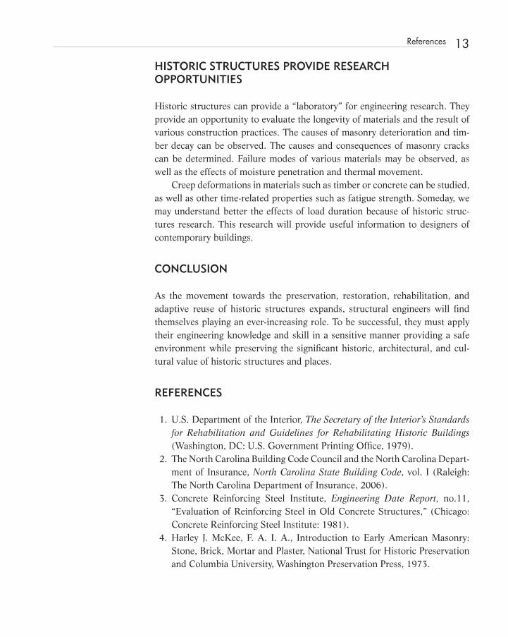
HISTORIC STRUCTURES PROVIDE RESEARCH OPPORTUNITIES
Historic structures can provide a “ laboratory ” for engineering research. They provide an opportunity to evaluate the longevity of materials and the result of various construction practices. The causes of masonry deterioration and tim-ber decay can be observed. The causes and consequences of masonry cracks can be determined. Failure modes of various materials may be observed, as well as the effects of moisture penetration and thermal movement.
Creep deformations in materials such as timber or concrete can be studied, as well as other time - related properties such as fatigue strength. Someday, we may understand better the effects of load duration because of historic struc-tures research. This research will provide useful information to designers of contemporary buildings.
CONCLUSION
As the movement towards the preservation, restoration, rehabilitation, and adaptive reuse of historic structures expands, structural engineers will fi nd themselves playing an ever - increasing role. To be successful, they must apply their engineering knowledge and skill in a sensitive manner providing a safe environment while preserving the signifi cant historic, architectural, and cul-tural value of historic structures and places.
REFERENCES
1. U.S. Department of the Interior, The Secretary of the Interior ’ s Standards for Rehabilitation and Guidelines for Rehabilitating Historic Buildings (Washington, DC: U.S. Government Printing Offi ce, 1979).
2. The North Carolina Building Code Council and the North Carolina Depart-ment of Insurance, North Carolina State Building Code , vol. I (Raleigh: The North Carolina Department of Insurance, 2006).
3. Concrete Reinforcing Steel Institute, Engineering Date Report, no.11, “ Evaluation of Reinforcing Steel in Old Concrete Structures, ” (Chicago: Concrete Reinforcing Steel Institute: 1981).
4. Harley J. McKee, F. A. I. A., Introduction to Early American Masonry: Stone, Brick, Mortar and Plaster, National Trust for Historic Preservation and Columbia University, Washington Preservation Press, 1973.
References 13
c01.indd 13c01.indd 13 12/18/08 10:06:20 PM12/18/08 10:06:20 PM
14 Historic Structures: The Role of the Structural Engineer
5. Brick Institute of America, Technical Notes on Brick Construction, No. 39A (City: Publisher: 1975).
6. American Institute of Timber Construction, Timber Construction Manual 2nd ed. (New York: John Wiley and Sons, Inc.: 1974).
7. U.S. Department of Agriculture, Forest Service. Forest Products Labora-tory , Handbook, no. 72, Wood Handbook (Washington, DC: U.S. Govern-ment Printing Offi ce, 1974).
8. National Forest Products Association, National Design Specifi cation for Wood Construction (Washington D.C.: National Forest Products Association: 1977).
c01.indd 14c01.indd 14 12/18/08 10:06:20 PM12/18/08 10:06:20 PM
15
C H A P T E R 2 Preservation and Public Safety : Structural Safety of Historic Timber Structures
M Meeting the requirements of the building code is not the same as assuring the public of a safe structure. Structural engineers have the training and expe-
rience to make the necessary judgments needed to keep a historic structure in service when parameters appear to fall short of minimum code requirements.
TIMBER MISUNDERSTOOD
Timber is the primary structural component for most historic structures in the United States and Canada. Although the structures might also include brick and stone masonry, iron, steel, or concrete, timber is often the most misunder-stood construction material of all. Part of the misunderstanding lies in our educational system. Many structural engineers earn degrees in structural engi-neering without ever taking a course in timber design. It is unfortunate that in North America, with our tremendous stock of timber - framed buildings and our strong forest products industry, more structural engineering curricula do not include at least introductory courses in timber design.
c02.indd 15c02.indd 15 12/18/08 10:06:55 PM12/18/08 10:06:55 PM
Structural Investigation of Historic Buildings: A Case Study Guide to Preservation Technology for Buildings,Bridges, Towers, and Mills. David. C. Fischetti © 2009 John Wiley & Sons, Inc.

16 Preservation and Public Safety : Structural Safety of Historic Timber Structures
In today ’ s residential market, timber is primarily of importance as dimension lumber. Most timber production consists of dimension framing, prefabricated trusses, stress - rated panels, and other components. The size of residential fram-ing members is dictated by building codes for various spans and conditions.
Manufacturers provide the design for prefabricated components such as wood trusses and joist substitutes. As a result, the glued laminated timber industry is one of the few areas where structural engineers are practicing the design of heavy timber structures on a daily basis.
PRESERVATION PHILOSOPHY
It is hoped that by learning more about timber design, structural engineers will develop a preservation philosophy that demands rigorous analysis in order to justify “ doing nothing ” to a historic timber structure that has been performing satisfactorily for many years. Buildings that analysis (and observation) clearly indicate are unsafe would be reinforced in the most sensitive manner in an attempt to retain as much historic fabric as possible. Buildings that require extensive modifi cation or reconstruction would be restored in a way that is in keeping with the original construction if possible, while fulfi lling safety require-ments. Often, engineers are asked to evaluate framing members to determine the capacity of an existing fl oor structure in a historic structure. This review process differs considerably from design.
STRUCTURAL REVIEW
Members in the horizontal plane — such as fl oor sheathing, joists, purlins, and beams — are stressed principally in bending. The resisting bending moment is a measure of the strength of such an element. This measure, stiffness, and hori-zontal shear make up the three qualities that are normally checked during the process of selection that we call design. Because timber is available in certain standard lumber sizes, the designer selects from the available sizes, grades, and species those that most economically meet the predetermined standards for bending stress, defl ection, and horizontal shear. When the engineer reviews the capacity of an existing member, many parameters complicate the process of selecting appropriate lumber. Size, span, and spacing of members are dictated by the structure. It is the engineer ’ s task to determine the size, orientation, species, grade, and end condition of all of the structural elements in a building that already exists. Between the factors of limited availability of types of lumber,
c02.indd 16c02.indd 16 12/18/08 10:06:56 PM12/18/08 10:06:56 PM
economic considerations, existing standards, and the structure of the building itself, freedom of choice is eliminated.
ENGINEERING JUDGMENT
Often, the structural engineer must pass judgment on a structure that has endured far beyond what we consider to be a normal period of service. The timbers of such a structure were not selected on the basis of modern engineer-ing analysis. They certainly do not bear inspection marks attesting to their grade and species.
It should be obvious to the engineer that a safe fl oor structure should not fail in bending due to the actual loads imposed. But it is important to recognize that excessive defl ection, excessive vibration, or a lack of stiffness, should not auto-matically categorize a fl oor structure as “ unsafe ” . Strict defl ection limitations should be set for fl oors that support plaster ceilings in lieu of wood or tin ceil-ings, or no ceilings at all. But for comfort, the defl ection limitation set in most building codes for fl oors, no matter what the ceiling, is 1/360th of the span.
It must be said that overstressed structural members may also be perfectly safe. It is important for the engineer to evaluate the basis for his conclusion regard-ing the safety of the structure. When making such an evaluation, the loads assumed for design should be reconciled with the actual loads that will occur in service. The design values that we assume are critical to the computed capacity of some fl oor systems include factors of safety of 2.5 to 3.0. For structures such as mill build-ings, average design values yield results that fall well above the minimum code requirements for adaptive reuse occupancy, such as residential, offi ce, or retail.
The actual distribution of loads in a structure, similar to live load reduc-tion factors for tributary area, can account for the continued service for heavily loaded members such as stair and fi replace headers, and summer beams that may appear to the engineer to be grossly undersized. Many times, these mem-bers defl ect more than is desirable for comfort.
LOAD DURATION AND HISTORIC STRUCTURES
The concept of load factor design is currently making its way into the fi eld of timber design. This concept is most appropriate for application to timber design because of the long history of the concept of live load duration . Early timber research found that timber reacts quite well to short applications of
Load Duration and Historic Structures 17
c02.indd 17c02.indd 17 12/18/08 10:06:56 PM12/18/08 10:06:56 PM

18 Preservation and Public Safety : Structural Safety of Historic Timber Structures
load. The duration of load was found to be as critical as the magnitude of the load. Presumably, this sensitivity to the duration of load is a result of the natu-ral composition of timber, which consists of a tightly bound bundle of cells that tend to stretch or elongate with time. The larger and more constant the load, the more stretching of fi bers occurs. The effects of this creep can be seen in many timber structures through excessive defl ection. For short durations of load, allowable design values are increased substantially.
Research into this time - versus - stress relationship is of paramount impor-tance. Only through evaluating historic timber structures can we solve this puzzle, which is complicated by cyclic loading, original moisture content, mem-ber size, span, species, grade, temperature, humidity, and magnitude of stress.
REPLACEMENT - IN - KIND
Often, replacement - in - kind is not economically feasible. More advances are being made in the fi eld of timber design than in any other area of structural engineering. Recent products include laminated veneer lumber and numerous other beam and joist substitutes. The most important benefi ts of these recon-stituted wood products is the availability of long lengths, higher design values, and greater stiffness. Preservationists and preservation engineers must deter-mine the appropriateness of these materials to each case.
CASE HISTORIES
Presented here are several projects that required us to determine the load capacity or safety of an existing fl oor structure. The Montague Building is dis-cussed further in Chapter 6 .
Chowan County Courthouse In a 1988 structural evaluation report, we concluded that the large second fl oor assembly hall of the Chowan County Courthouse in Edenton, North Caro-lina (c.1767), could be used for public occupancy if the area would be posted to limit the number of people to 200. A defl ection limitation of 1/360th of a span governed the design, producing a bending stress as high as 2,292 psi in large, dense southern pine timber fl oor joists and beams.
Walker Building Sometime later, we reviewed the fl oor structure of the 1917 Walker Building at the State Hospital in Concord, New Hampshire. Assuming a reasonable set of
c02.indd 18c02.indd 18 12/18/08 10:06:57 PM12/18/08 10:06:57 PM

design values equivalent to No. 1D SR southern pine, based on examination of a wood sample obtained from the building, and a visual inspection of the fram-ing, we concluded that the existing 7 ½ � 11 timber beams were adequate to support a live load of 86 psf. This is well within the 50 psf required for offi ce occupancy with fi xed partitions. The live load defl ection limitation of 1/360th of the span controlled the design. Of course, we concluded that this was a safe structure that met minimum code requirements. The calculations were based on reasonable assumptions of design values.
Montague Building In 1985, at my direction, six fl oor joists from the 1903 Montague Building in Raleigh, North Carolina, were tested to destruction. Of the fi ve joists tested (of six joists selected; one was found not suitable for testing), the average bending stress at rupture was in excess of 5,000 psi. The average modulus of elasticity was 1,295,000 psi. These measures of strength and stiffness were used to evaluate the capacity of the fl oor structure. To meet tenant loads for possible retail occupancy in this speculative offi ce building, I recommended that all of the existing fl oor joists be reinforced. (The Montague Building is also discussed in Chapter 6 ).
Moorfi elds At Moorfi elds, a 1792 house in Hillsborough, North Carolina, the excessive defl ection of a summer beam was evaluated by measuring offsets in the fl oor surface above the beam. Based on fi eld measurements and computer analysis, I was convinced that the summer beam had failed. Indeed, when exposed to view during construction by removing the ceiling plaster, the summer beam contained a severe fracture consistent with a typical bending failure. The only replacement beam available of suffi cient stiffness and strength that would fi t between in the space between the fl oor sheathing and the ceiling was a steel tube section approximately equal to the original timber beam in size.
CONCLUSION
Only through specialized knowledge and experience can structural engineers make the necessary judgments needed to properly evaluate historic timber structures. The engineer must be convinced that the structural model in the computer is an accurate representation of actual conditions. Once that is clear, the application of rigorous analysis, testing, and engineering judgment may be necessary to explain why the historic timber structure in question has per-formed adequately for many years.
Conclusion 19
c02.indd 19c02.indd 19 12/18/08 10:06:57 PM12/18/08 10:06:57 PM

21
C H A P T E R 3 Simplifi ed Engineering *
INTRODUCTION
T T he fi eld of structural engineering has grown more complex as we begin the twenty - fi rst century. The profession of structural engineering evolved from
principles fi rst developed in the 1840s by American pioneers such as Squire Whipple (1804 – 1888) and Herman Haupt (1817 – 1905). These men were among the fi rst to publish engineering pamphlets and textbooks based on rational mathematical or graphical analysis of simple structures. At that time, the unparalleled growth of the railroads required that reliable methods of anal-ysis be invented for bridge construction.
In the last few years, events and certain attitudes have combined to pro-duce a highly complicated world for practicing engineers. Methods of analysis have grown more complex. For many years, the fundamental principles neces-sary for the design of simple structures did not change. Now, advances in com-puter technology, applications, and usage, stronger materials, composite and orthotropic materials, and plastic or load [resistance] factor design applica-tions have changed the ways buildings and bridges are designed. Other require-ments, such as continuing education, peer review, and changes in registration laws are thrust upon the engineer in an effort to obtain more accountability.
* This paper was originally written for the Fall 1995 Lecture Series, Sponsored by The Structural Group Boston Society of Civil Engineers, Section American Society of Civil Engineers.
c03.indd 21c03.indd 21 12/18/08 10:07:30 PM12/18/08 10:07:30 PM
Structural Investigation of Historic Buildings: A Case Study Guide to Preservation Technology for Buildings,Bridges, Towers, and Mills. David. C. Fischetti © 2009 John Wiley & Sons, Inc.

22 Simplifi ed Engineering
In order to be more productive and effi cient in the areas that we can control, engineers might consider the concept of simplifi ed engineering.
WHAT IS SIMPLIFIED ENGINEERING?
Simplifi ed engineering is a method of reducing the complexity of a problem by exercising the engineering judgment of an experienced designer in order to eliminate unnecessary procedures and methods not essential to arriving at a solution.
When pressed, designers are tempted to take shortcuts in order to produce an acceptable set of plans and specifi cations in the shortest length of time. In recent years, consulting structural engineers have, during the design process, received fewer dimensions, details, wall sections, and building sections pro-duced by architects. The consulting structural engineers are fi lling in some of the gaps, because we have no choice but to describe the complete structure. There are few shortcuts to producing a complete set of structural design docu-ments. As a result, many engineers are practicing simplifi ed engineering.
Many in the engineering profession look toward the medical and legal professions as a gauge of our success. Unfortunately, engineers are rapidly los-ing ground in the one area that offers a quantitative comparison: monetary compensation. Unlike medical and legal fees, which are cumulative, engineer-ing fees are usually based on fi xed fi nancial considerations and represent a slice of a pie. In most instances, owners, developers, fi nancial institutions or architects decide what size the pie will be and how it will be divided among the consultants.
In certain projects, the slice for the structural designer becomes even thinner when complexity dictates that additional consultants be added. A project may have building code, seismic, geotechnical, acoustical, lighting, roofi ng, landscape, waterproofi ng, theater, natatorium, security, curtain wall, sprinkler, and other spe-cialty consultants. Not only can the limits of responsibility become ambiguous, but also, coordination between the various specialties is often diffi cult or nonexistent.
For most ordinary buildings, analysis is a very small part of the effort. The production of a fully coordinated set of plans and specifi cations employs most of our time. Often, a project is drawn fi rst, and then engineered. At a time of rising expectations and diminishing returns, engineers need methods of expe-diting their work without reducing quality. By rapidly advancing the produc-tion of plans and specifi cations through the initial stages of design, simplifi ed engineering may be one method of reaching the goal of producing a design that
c03.indd 22c03.indd 22 12/18/08 10:07:30 PM12/18/08 10:07:30 PM

meets all of the requirements of the project. This can be a shortcut to a solution based on sound engineering judgment, resulting in the appropriate effort applied to various tasks.
Simplifi ed engineering becomes a critical issue when it is practiced as a response to unwieldy or diffi cult computer software. To use most structural software, the designer requires a block of uninterrupted time. If this time is not available, the designer may abandon the software in favor of a less accurate hand calculation. In some cases simplifi cation may actually yield more accurate fi nal results. For example, a plane frame analysis of a three - dimensional steeple structure may afford the engineer an opportunity to “ get the feel ” of the structure when compared to a three - dimensional analysis with its complicated coordinate system, which results in reams of pages of output. The cost of increased accuracy in engineering calcula-tions is a decreased sense and understanding, or feel for the numbers — particularly, the results. It is reasonable to expect that the design engineer will have a sense of an expected range of results prior to performing the calculations.
The computer industry lags far behind in the production of effi cient user - friendly software for structural engineers. Although great advances have been made in the development of faster general plane frame analysis programs with more capacity, design programs for individual beam and column members are often unwieldy. For example, some Composite Steel Beam Design programs require two pages of printout for each beam analyzed. Traditionally, structural engineers have “ batched ” tasks, analyzing all columns at one time, or all simi-larly loaded beams together. One 8 ½ � 11 sheet of printout should be suffi -cient to display the output for 12 to 24 beams or columns. Anton Tedesko pointed out in a recent issue of Civil Engineering magazine that computers have not “ diminished the value of back - of - an - envelope calculations. ” 6
Computer analyses are of great help when used in the proper context, when modeling of the structure is correct, when the actual boundary condi-tions are taken into account and the output is examined and interpreted by an experienced engineer. It is a misconception, however, that sophisticated com-puter analyses through greater accuracy will lead to better designs. The quality of a design is not a function of the exactness of the calculations, and it is not necessary to strive for great accuracy in a numerical analysis when the accuracy of the assumption is not known.
Many of the calculations made today are not necessary. Sometimes calcula-tions are produced because the analyst is fascinated with the program or is taken in by the sheer beauty of the analysis. At other times, someone wants to show how many pages of calculations have been produced; sometimes this is done to impress a client.
What is Simplifi ed Engineering? 23
c03.indd 23c03.indd 23 12/18/08 10:07:31 PM12/18/08 10:07:31 PM

24 Simplifi ed Engineering
A complicated analysis performed on a computer may not necessarily be an accurate model of the structure to be designed. The engineer must use judg-ment to decide what elements should be removed from the overall structure in order to simplify the problem. Computer analysis allows the designer to search for various solutions in a matter of seconds. Boundary conditions such as springs can be tried. The computer allows us to achieve a very reasonable model in a short period of time. Our best designs may still be simplifi ed ver-sions of parts of a structure with added opportunities to input nonprismatic sections and sophisticated boundary conditions. Antonio M. Garcia, P.E., described this state of affairs in an August 1993 issue of Civil Engineering magazine:
With available structural design software, we can represent any structure on a screen, apply any load in any direction, and receive output on stresses at any or all nodes. We can also pictorially represent the defl ected structure or, by use of color variations, picture the intensities of tensile and compressive stresses. In essence, much of what used to be intuition or “ feel ” based on experience has been replaced by highly sophisticated software and extremely fast hard-ware: Anyone with funds and little experience can achieve what once took years of training. The fallacy lies in believing that reams of output providing every bit of incredibly accurate information are enough to solve the problem. Experience cannot be purchased; it must be acquired. The fact that an answer is achieved does not necessarily mean that it is the right answer.
No matter how sophisticated the computer, the engineer needs to under-stand the materials and construction methods used. The fi nished plans represent the designer ’ s intentions, and they must be realistic. 1
The computer, used by an experienced designer, becomes a powerful tool. Carelessly used, it can result in a dangerous sense of well being and satisfaction in a design that may have serious shortcomings. As the computer reduces cal-culation time, it also reduces the time spent on a project, thereby reducing the time we spend thinking about the project with all of its intricacies and details. We thus lose the time spent “ sleeping on it ” that can give us a clearer picture of a project and its idiosyncrasies.
HOW CAN SIMPLIFIED ENGINEERING BE PRACTICED?
Simplifi ed engineering is practiced every day on thousands of projects when we choose what to analyze and how to approach the analysis. The more experienced an engineer is, the greater the latitude should be.
c03.indd 24c03.indd 24 12/18/08 10:07:31 PM12/18/08 10:07:31 PM
Engineers have simplifi ed their work for many years through the use of handbooks. Often the use of handbooks requires the engineer to interpolate between tabulated values. In many cases a code mandated requirement will govern the design. For example, in concrete, #4 reinforcing steel spaced 12 inches on center may be the minimum reinforcing recommended by the American Concrete Institute for a specifi c application. A designer might make the mini-mum steel beam size a W10x14 to allow suffi cient depth for clip angle connec-tions with space for a minimum of two rows of bolts. The Underwriters Laboratory might require a minimum composite beam size of W8x28 to obtain a certain fi re resistance rating. With minimum requirements in place, the design effort is simplifi ed by omitting the design of elements, which, by inspection, exceed the minimum requirements for stiffness and strength.
The Hyatt - Regency walkway collapse in Kansas City and recent economic forces have changed the way structural engineers work. Previously, the engi-neer of record had more back - up. Steel companies were then staffed with com-plete engineering departments. The steel company ’ s engineers would review a project prior to bidding and construction, adding their input to the estimating and detailing efforts.
Now, with steel companies employing minimal engineering staffs consist-ing of contract drafters located at remote sites, the engineer of record does not benefi t from “ another pair of eyes ” looking at a project. The profession and the steel industry have redefi ned the roles of the various parties. From connection design to “ standard details, ” the steel fabricator assumes no responsibility. Many fabricators do not check shop drawings prior to submittal, thus shifting more of the burden onto the structural designer of record.
WHEN IS SIMPLIFIED ENGINEERING A VALID METHOD?
Simplifi ed engineering is a valid method to use when the result produces an adequate design. If the engineer is responsible when designing, there is not a problem with this method as it has been used traditionally. Our natural tendency has been to simplify everything into a model that is complex enough to accu-rately describe the structure to be designed, yet is simple enough to be analyzed. For example, truss analysis for many years assumed members to be prismatic sections with pinned joints. This facilitated analysis by such means as the method of joints. Now that we can create more complex models by computer, introduc-ing some rigidity at joints and continuity in individual pieces, are we irresponsi-ble when we abandon the computer and do a quick hand calculation?
When is Simplifi ed Engineering a Valid Method? 25
c03.indd 25c03.indd 25 12/18/08 10:07:31 PM12/18/08 10:07:31 PM

26 Simplifi ed Engineering
WHO CAN PRACTICE SIMPLIFIED ENGINEERING?
Any engineer can practice some form of simplifi ed engineering. Even the new-est EIT (Engineer - in - training) can be faced with a problem, for which his edu-cation did not prepare him, the fi rst day on the job. Ideally, he would be working under the direct supervision of a more experienced engineer who would guide him toward a simplifi ed approach. The more experience an engi-neer has, the more ability the engineer would obviously have for simplifying calculations based on knowledge of the subject and feel for the numbers and expected outcome.
ADVANTAGES, DISADVANTAGES AND POTENTIAL PROBLEMS
Percival White wrote the following in the July 1920 issue of The Atlantic Monthly:
Effi ciency is fondly regarded in the American mind as the greatest contribu-tion of this age to civilization. It is deemed an agency for good, a thing one cannot have too much of.
Effi ciency is a lightning calculator, by which you may convert time into anything you like, and read the answer in percentages, to the third decimal place. By its means, for example, you may change minutes into dollars, which is, after all, the thing most of us are trying to do.
Yet there is danger in these glib conversions. Money is a tangible thing. The more you save, the more you have. But time is far more subtle stuff. Sav-ing it does not imply having it. As soon as a man seriously starts saving time, make up your mind that he will no longer have a moment to spare. 2
The greatest advantage of simplifi ed engineering is the time it saves. The greatest disadvantage is that the solution may not be accurate. Potential problems may arise when drawings or calculations are reviewed at a later date. Simplifi ed engineering may cause great diffi culty to a peer reviewer unable to follow the thinking of the engineer of record or not in agreement with the methodology. Certainly, if the design has to be defended because of an observed problem in the fi eld during construction or after completion, simplifi ed engineering can result in lawsuits on the basis of negligence. Sim-plifi ed engineering, practiced as a response to outside pressure such as fee or time constraints, does a great disservice to the project. Most clients are con-cerned with schedule. However, quality is infrequently discussed. It is assumed that any structural engineer will produce basically the same design.
c03.indd 26c03.indd 26 12/18/08 10:07:32 PM12/18/08 10:07:32 PM

Does the client care whether the columns in a building frame are to be designed by computer considering bi - axial bending due to possible eccentric-ity, or merely selected from a handbook?
Discussion of simplifi ed engineering with owners, clients, and non - engineering professionals is risky. The decision of whether to simplify a portion of the analysis should be left to the engineer of record. Discussion with nonengineering profes-sionals of simplifi ed engineering may lead them to think that engineering design is simple or that it can be simplifi ed. The client ’ s natural conclusion would be that they should expect a quick turnaround for a reduced fee.
HISTORICAL PERSPECTIVE: RULES OF THUMB VERSUS ANALYSIS
In American structural engineering, analysis as we know it today grew out of the work of many engineers practicing in the fi rst half of the nineteenth cen-tury. They attempted to determine accurate methods of analysis to solve prob-lems that had previously been solved using rules of thumb. Rigorous mathematical methods of analyzing the forces and stresses in framed struc-tures, such as bridges, were unknown until the 1840s. Structural engineers Squire Whipple and Herman Haupt independently developed mathematical truss design methods. In 1842, Haupt produced a small pamphlet, Hints on Bridge Construction by an Engineer.
Whipple is credited with developing the scientifi c basis of bridge design in the United States with his 1847 publication, “ A Work on Bridge Building. ” In 1851, Haupt produced his major work, General Theory of Bridge Construc-tion . Earlier bridge builders such as Timothy Palmer, Theodore Burr, Lewis Wernwag, and Ithiel Town very likely used various methods to determine stresses and strains. It is not now known whether their methods of proportion-ing members were based on mathematics or rules of thumb. However, in 1820, Town advertised his patent for the plank lattice truss by inviting potential investors to “ examine the model and the mathematics. ”
Code of Design Often, mandated code requirements force engineers to design beyond the limits of good engineering judgment. For example, it may be obvious to the designer that certain loading conditions will not be necessary because of the confi gura-tion, construction type, location, or occupancy of a building.
We have seen wind - , snow - , and seismic - mandated code requirements increase in complexity in recent years. Wind load factors, snowdrift coeffi cients,
Historical Perspective: Rules of Thumb Versus Analysis 27
c03.indd 27c03.indd 27 12/18/08 10:07:32 PM12/18/08 10:07:32 PM
28 Simplifi ed Engineering
and seismic analysis methods have greatly increased the complexity of structural design for the typical building. Supposedly, complicated and unwieldy loading conditions are a result of more accurate scientifi c or engineering research. But, at the same time, the coeffi cients provided in the current building codes often result in less snow, wind, or seismic force being applied to a structure com-pared to what the previous codes would have required. Most practicing engi-neers, if given the choice, would opt for the simpler series of loads, knowing full well that they might be conservative.
From a structural engineer ’ s standpoint, there should be provisions in the code for alternate simple load provisions for wind, snow, and seismic design at this time when fees for architectural and engineering services are shrinking, and the expectations of our clients are rising. It is debatable whether the design community is designing safer structures today because of the complicated snow-drift, wind loads, and seismic requirements than we did with the earlier codes.
Timber Design Although wood is a very complicated building material, for 150 years it has been simple to design. The 1991 National Design Specifi cation for Wood Con-struction (NDS) changed what was for many years a simple column formula into a more complex mathematical expression — an example of increased com-plexity in timber design. The previous design procedure shown in the 1985 edition of the Timber Construction Manual and earlier editions of the NDS was recently revised to include a column - stability factor based on a procedure proposed by A. Yline in 1956.
This method permits estimation of the buckling stress and the required cross - sectional area for concentrically applied loads on straight columns in the elastic and inelastic ranges. The column stability factor is a complicated equa-tion. Bruce Pooley, director of technical services for the American Institute of Timber Construction, admits, “ Calculating Cp is lengthy when done by hand, but quickly computed with a programmable calculator, a computer spread-sheet, or any one of a number of software programs developed for wood design. ” He indicated that the new design method was “ equation based, ” mean-ing that it was assumed that practicing engineers would program the equation into their computers, thus reducing the pain of dealing with such a compli-cated set of mathematical expressions. 7
Load Resistance Factor Design For many applications, load factor design seems to be a design methodology that overly complicates the design process for the average engineer. Some proponents
c03.indd 28c03.indd 28 12/18/08 10:07:32 PM12/18/08 10:07:32 PM

believe that now that we have computers, it does not matter how complicated the math is. Programs are viewed as a black box, a sort of mixing bowl, where the ingredients are placed without regard to the internal process but with com-plete confi dence in the results.
To the practicing engineer, LRFD is an unwieldy method of design pro-moted by the academic community and various large engineering fi rms. Allow-able stress design gives the designer “ real ” numbers for use in a simple world where the design is either “ OK ” or “ no good. ” Working stress design is simple and commonly understood. Stress is proportional to strain below the elastic limit. Why would an engineer want to delve into that domain above which elastic materials begin to yield? Ultimate strength design, which originated for concrete in the 1956 and 1963 American Concrete Institute specifi cations, required nearly a quarter of a century to replace working stress design.
Vibratory Analysis Several years ago, the issue of fl oor vibration was considered by the North Carolina State Building Code Council for incorporation into the building code. This came at a time when the expectations of consumers were rising. In North Carolina, complaints regarding excessive fl oor vibration in residential struc-tures caused the Structural Committee of the Building Code Council in 1991 to consider making vibratory analysis part of the building code at roughly the same time that the CABO code was being adopted.
At the time, some argued that the Building Code Committee should not recommend that a vibratory analysis, by a professional engineer, be a required part of the code because the vibratory response of a fl oor is independent of its structural capacity. The vibratory response of a fl oor is diffi cult to quantify, and requiring a vibratory analysis in the building code would lead to increased liti-gation for real or imagined problems that are not a measure of safety. A sugges-tion was made to simplify the problem by placing in the code minimum depth - to - span recommendations that have been shown to minimize vibratory problems. That advice was not implemented, and code mandated vibratory analysis was avoided for the time being.
Seismic Design In light of the earthquakes in Northridge, California, and Kobe, Japan, engi-neering researchers are rethinking the current approach to seismic design. Research undertaken at the present time will result in almost immediate changes in the building codes. Seismic design is a market to exploit. Grant monies for studies and research is fl owing from Washington in response to
Historical Perspective: Rules of Thumb Versus Analysis 29
c03.indd 29c03.indd 29 12/18/08 10:07:33 PM12/18/08 10:07:33 PM

30 Simplifi ed Engineering
major earthquake activity. Large design fi rms armed with grants can target areas of the country susceptible to seismic activity and market their specialized expertise, fi lling a void the local consultants may have discounted. Seismic damage makes great television press. Municipal, hospital, school, and other administrators cannot ignore the risks associated with a major earthquake. The more complicated the analysis needs to be, the more important it is to hire specialists to design seismic resistant foundations and buildings, and to deter-mine how to modify the underlying soils or isolate the foundations of existing buildings. Will the academic community and code offi cials recommend simple methods of analysis that can be applied easily to new and existing buildings in order to reduce the risk of damage during a seismic event? Probably not.
Several questions should be asked before we adopt complicated or exces-sive seismic requirements into our building codes. First, what is the risk of injury, death, or property damage in the United States due to a seismic event? Second, how much will seismic provisions add to the cost of rehabilitating or adding to existing structures? Third, how much will a seismic analysis add to the cost of engineering and architectural fees for new or existing structures? Fourth, how many clients will be willing to pay extra for a seismic analysis?
History since 1750 indicates that in most of the United States, the risk of death or property damage from a seismic event is extremely small. There are many reasons for the low seismic mortality rate. Population density, construc-tion methods and materials, geotechnical conditions, and climate are some of the factors that affect the number of deaths that may occur as a result of a seismic event. North American building codes and zoning ordinances limit population density in our cities. Cultural factors tend to limit the number of children living in single - family dwellings in North America.
Construction methods in North America tend to limit the risk of earth-quake - related deaths. One of the methods worth mentioning involves the use of mortar and unit masonry, which is far superior to the unit masonry used in many less - developed countries today or in any country in the past. Joint rein-forcing is included in most commercial masonry walls built in North America. Many residential buildings in North America are framed with dimensional lumber, which is light and strong. Except in certain regions, North American builders tend to not roof buildings with heavy concrete or clay tile products.
Buildings constructed in North America today are required by building codes to bear on properly proportioned footings resting on an adequate subgrade. In many overpopulated parts of the world, housing is constructed on steep slopes or fi lled in land not suited for agriculture or other activities. In American cities, such as Charleston, Boston, and San Francisco, which are underlaid with soft clays, pile, or caisson foundations are typically provided for large buildings.
c03.indd 30c03.indd 30 12/18/08 10:07:33 PM12/18/08 10:07:33 PM

All of the existing buildings in North America are new when compared to many of the buildings found in other parts of the world. But the most impor-tant single factor pertaining to absence of property damaged or deaths during past seismic events is the absence of large seismic events.
The East Coast has, no doubt, experienced many earthquakes, although the Appalachian mountain chain is one of the oldest, seismically inert ranges in the world. Records dating from 1750 indicate that although 2,750,000 people have died as a result of earthquakes worldwide, the record in the United States is very good and most states have not yet recorded a fatality.
Table 3 - 1 Major Earthquakes in the United States Since 1750
State # of major earthquakes
Largest number of deaths in one event Date Total # of deaths
Alaska 4 131 March 27, 1962 134
California 10 667 April 18, 1906 1049
Idaho 1 2 Oct. 28, 1983 2
Hawaii 2 173 April 01, 1946 234
Massachusetts 1 0 Nov. 18, 1755 0
Missouri 3 10 Dec. 16, 1811 10
Montana 3 2 Oct. 11, 1936 30
Nevada 3 0 Dec. 16, 1954 0
Oregon 2 2 Dec. 4, 1993 2
South Carolina 1 83 Aug. 31, 1886 83
Texas 1 0 August 16, 1931 0
Utah 1 0 March 12, 1934 0
Total 32 1544
The total number of deaths from earthquakes since 1750 in the United States is 1544. The earthquake - related deaths in Hawaii were the result of tidal waves. The 1886 earthquake in Charleston, South Carolina, is the only major earthquake to be located on the East Coast. The deep layer of marl beneath Charleston is one reason for the heavy damage. St. Philip ’ s and St. Michael ’ s Churches in Charleston, South Carolina, were both badly damaged. Although the heavy steeples of both churches settled almost a foot, both buildings were repaired and have continued in service since 1886. Similarly, they were repaired after tornadoes and hurricanes such as Hugo in 1989. In the Winter 1990 issue
Historical Perspective: Rules of Thumb Versus Analysis 31
c03.indd 31c03.indd 31 12/18/08 10:07:34 PM12/18/08 10:07:34 PM
32 Simplifi ed Engineering
of Wood Design Focus , Ario Ceccotti presented an earthquake performance challenge to researchers, code writers, and designers:
It is evident that thorough knowledge and planned balance of the positive and negative aspects will yield a proper design that guarantees structural safety at a reasonable cost.
Researchers have the challenge of quantifying the factors that yield duc-tile behavior and energy dissipation in the structure. They can determine how to design and detail connections that lead to ductile systems, rather than brit-tle failures.
Code writers have the challenge of combining the often - disparate results of research. They must present a few relatively simple and conservative design rules, which are easy to apply, for the most common structural forms (those with known ductility and dissipation levels). Yet, for less common structures, for which experience has demonstrated good structural performance, code writers must provide simple rules or guidelines based on the engineering judgment.
Designers have the challenge of fi nding the best solution among the vari-ous ductility classes, creating the most convenient design from technical and economical points of view. 3
The application of complicated seismic requirements, which are subject to wide interpretation, will only cause the demolition of many existing buildings. For example, to accurately determine the seismic resistance of an existing building, the unit weight and shear capacity of the existing masonry must be known. This requires expensive testing in the fi eld to obtain design values to be used in the analysis, which owners are often not willing to pay for.
Proposed seismic provisions for building additions will affect the historic preservation and the renovation and rehabilitation segments of the construc-tion industry. Many owners faced with rehabilitating or adding to an older or historic structure will elect to demolish when faced with engineering fees for evaluation, or potentially unknown construction costs, required to bring a building into conformance with seismic provisions. For example, to construct a structurally independent stair and elevator tower addition is a diffi cult and expensive task. Usually, part of the new elevator lobby is supported by the existing structure at each fl oor level.
Upcoming changes to the seismic provisions of the building code should exempt existing one - story buildings with wood framing or unit masonry load - bearing walls from the seismic provisions of the code and all other buildings in the Seismic Hazard Exposure Group I category. However, structures with pre-cast concrete structural systems or unusually heavy roof systems should be included in a special hazard category. Certain elements such as architectural
c03.indd 32c03.indd 32 12/18/08 10:07:35 PM12/18/08 10:07:35 PM

stone cladding, large chimneys, and masonry parapets above a certain height should be subject to seismic review in all cases.
Based on the limited risk of a seismic event in most of the United States, it is in the best interest of the public, the construction industry, and architectural and engineering professions, to limit the complexity of the seismic code and its application to existing buildings.
When California and Hawaii are excluded, we have suffered a total of 261 deaths from earthquakes in 245 years. More structural engineers in the United States will die from heart attacks due to stress — caused, in part, by an effort to implement a complicated seismic code — than all of the earthquake victims combined.
Code versus Creativity In the movie Brazil , Robert De Niro ’ s character, Harry Tuttle, is a heating engi-neer illegally providing mechanical repairs outside the government ’ s inept Central Services branch. When Sam Lowery questions why he chose to work outside the system, Harry Tuttle replies that he “ couldn ’ t stand the paperwork . . . you can ’ t make a move without a form. ” “ Get in, get out, travel light . . . a man alone . . . ” is his philosophy as he provides much - needed emergency repair services, which are considered by the government to be sabotage.
As we dictate methodologies in our building codes in an effort to ensure uniformity in approach, do we stifl e creativity? Do we remove humanity from the design process as mandated design is implemented? Are mandated design meth-ods an attempt by some in the design community to ensure that designers con-form to a certain analysis - based ideal? In the future, will we have to depend on the Harry Tuttles, working outside of the system, to keep the system running?
Legal Implications The greatest legal implication of using simplifi ed engineering methods is the potential needed to defend our designs should they be challenged for whatever reason. Unfortunately, modern - day structural engineering is so complex that it is very easy for a sharp attorney armed with the testimony of expert witnesses to prove negligence.
Engineering Judgment: Engineer of Record The engineer of record should have some leeway with regard to analysis meth-ods used for a particular problem. At this time, we in the design professions are faced with the rising expectations of our clients, as well as a reluctance on their part to pay for professional engineering services. Schedules are often
Historical Perspective: Rules of Thumb Versus Analysis 33
c03.indd 33c03.indd 33 12/18/08 10:07:35 PM12/18/08 10:07:35 PM

34 Simplifi ed Engineering
compressed, leaving the designers very little time to produce documents, let alone time to cogitate and coordinate. The engineer of record has the ultimate responsibility for the design. Suffi cient time must be provided in the schedule for a thorough fi nal check and review of all the documents prior to bidding.
Third - Party Review Simplifi ed engineering can result in real problems in a project with third - party review if the reviewer does not understand the methodology or does not agree that the simplifi ed model is suffi ciently accurate to produce a correct result. Simplifi ed engineering can be a valuable tool for checking or verifying a design by others.
EXAMPLES OF SIMPLIFIED ENGINEERING: BUILDINGS
Residential structures constructed in the United States today are an example of simplifi ed engineering. The great majority of residential structures are not engineered, but built to minimum code standards that are based on standard tables developed for timber and masonry elements. The standard tables are often the results of empirical data derived from observing the behavior of structures over time.
As a result of Hurricane Andrew, we have complicated our codes with various wind - load factors and unrealistic loading conditions in order to pre-vent future damage from a similar storm as if a defi ciency in the code were the problem. Studies have shown that the code in South Florida was more than adequate, if followed, to produce buildings constructed well enough to resist wind forces generated by Hurricane Andrew.
The obvious defi ciency was in the execution of the design by the building contractors. Endwalls of gable - roofed buildings were pushed in by high wind forces because of the absence of endwall bracing required by code. Roof trusses lacked suffi cient tiedowns in spite of code requirements. In many damaged buildings, plywood sheathing was insuffi ciently attached and blocked to resist uplift and shear forces due to wind. The conclusion of the 1992 American Plywood Association report, no. T92 - 21, is not that we need to change the design requirements, but that a more thorough inspection is required during the construction phase to ensure that fasteners are installed as specifi ed:
Within a week after Hurricane Andrew battered the southern Florida region on August 24, 1992, American Plywood Association technical and fi eld pro-motion staff visited the region to inspect damaged and evaluate structural performance of residential and low - rise commercial structures.
c03.indd 34c03.indd 34 12/18/08 10:07:35 PM12/18/08 10:07:35 PM

The inspections were conducted in conjunction with inspections carried out under the auspices of a Damage Assessment Team, coordinated and arranged by the Florida Concrete and Concrete Products Association and endorsed by the state of Florida, Department of Community Affairs. The 45 - member team consisted of structural engineers, government and university scientists, build-ing code offi cials and technical representative of the building construction industry.
Conventionally built residential structures constructed with wood sys-tems performed satisfactorily when the structures were built to meet building code provisions. Residential structures constructed with masonry block walls also performed well, in general.
Failures involving plywood or oriented strand board (OSB) roof sheath-ing or wood - framed roof or wall systems could be traced to improper or inad-equate fastenings of connections to other components. Although extensive use of steel tension straps connecting roof - wall - fl oor framing was observed, the structural advantages offered by such connectors could not overcome defi cien-cies caused by omission of other code - required connections between building components. 4
When, as a consulting structural engineer, have you walked a deck prior to roofi ng, to count the number of fasteners and verify their correct attachment to the structural system below? To reduce wind damage during a meteorological event, all buildings should be given a structural review to verify that the correct fasteners were properly installed in suffi cient quantity. Is this task the responsi-bility of the building offi cial, an independent consultant, the contractor, or the designer of record? It is obvious that code - mandated inspections that compli-cate the design or construction process for the engineer of record will not solve the problem. It is unlikely that fees for structural engineers will increase to cover additional code mandated assurances placed on the designer.
An example of simplifi ed engineering with which few would argue is the analysis of an unequal - sided suspended two - way fl at concrete slab by assuming a square or rectangular shape with roughly the same proportions as the poly-gon. By setting a minimum thickness to ensure defl ection control and obtain-ing reinforcing steel size and spacing to resist the bending forces, an adequate slab can be designed. At no time would the exact long - term defl ection or exact maximum bending moment at any location be calculated. A serviceable design can thus be obtained without performing a sophisticated analysis.
BRIDGES
Bridges are built using simplifi ed engineering when components such as pre-stressed, precast concrete are selected from tables for short standard spans.
Bridges 35
c03.indd 35c03.indd 35 12/18/08 10:07:35 PM12/18/08 10:07:35 PM

36 Simplifi ed Engineering
Of course, the tables are produced by the most rigorous analysis methods. This type of simplifi ed engineering is often used at the Type Study Phase of bridge design as a tool for comparison of structure types and costs. Simplifi ed engi-neering, however, is not likely to be used in the fi nal design phase of a bridge. The standard code for bridges published by the American Association of State Highway and Transportation Offi cials (AASHO) has, like the building codes, increased in complexity. One example of the increased complexity can be found in the change of the distribution factor for wheel loadings on interior bridge girders. The spacing factor of S/11 will soon be changed to a much more com-plex expression. Fortunately for the designer, computer programs can be used for the calculation. However, the “ feel ” for the number becomes lost, if not nonexistent.
DESIGN PHILOSOPHY: DESIGN OF STRUCTURES
As present - day designers, we often are so immersed in our day - to - day operations that we seldom have the opportunity to formulate a rigorous design philosophy. We know how to perform our services, but do not always think much about the process. If asked, most of us would describe the methods we use in order to illustrate our philosophy. Most of us design structures from the top to the bottom for vertical loads fi rst. Then, after the horizontal and vertical members are selected, we determine which system to use to resist lateral forces. Although most engineers have three - dimensional design capability, we design buildings through analysis by separating orthogonal systems into components.
ENGINEERING EDUCATION
In the 1960s, the computer became the modern tool for analysis, and many practical courses disappeared from the structural engineering curriculum. First, Surveying was eliminated. Then, Mechanical Drafting and Freehand Drawing were combined into Graphic Analysis. Some design and drafting courses were dropped from the curriculum in favor of basic computer pro-gramming. The Maxwell diagram, the string polygon, and Bow ’ s notation are unknown to the younger generation of engineers. Yet, what simple but beau-tiful methods of analysis these were! Graphical analysis was so simple and logical that many truss manufacturers employed drafters to do this work. Pier Luigi Nervi remarked, “ I believe that graphical statics should play an important role in this last educational phase, since its procedures give a direct
c03.indd 36c03.indd 36 12/18/08 10:07:36 PM12/18/08 10:07:36 PM

understanding — much better than that afforded by analytical methods — of force systems and their composition, decomposition, and equilibrium. ” 5
Nervi is well known for his ideas regarding mathematical analysis in build-ing design. In the early 1950s, he wrote:
It is highly regrettable that some of the highest qualities of the human mind, such as intuition and direct apprehension, have been banned from our schools and have been overwhelmed by abstract and impersonal mathematical formu-las. We cannot forget that in the distant past intuition allowed the execution of works which cannot be analyzed today by the most modern theoretical meth-ods, and before which we must bow in reverent and humble admiration.
We cannot deny that the potentialities of mathematical methods are soon exhausted, even when their application is diffi cult and complex. Special, skin - resistant, and highly indeterminate structures cannot be analyzed by mathemati-cal theories, although they are extremely effi cient from a technical, economical, and architectural viewpoint.
Moreover, the most advanced chapters of theory of structures, which deal with the solution of statically indeterminate systems, can be used only to check the stability of a structure. They can be used only to analyze numeri-cally a structure already designed, not only in its general outline, but in all its dimensional relations. The formative stage of a design, during which its main characteristics are defi ned and its quality and faults are determined once and for all (just as the characteristics of an organism are clearly defi ned in the embryo), cannot make use of structural theory and must resort to intuition and schematic simplifi cations. 5
The essential part of the design of a building consists in conceiving and proportioning its structural system; in evaluating intuitively any dangerous thermal conditions and support settlements, in choosing materials and con-struction methods best adapted to the fi nal purpose of the work and to its environment; and, fi nally, in seeking economy. When all these essential prob-lems have been solved and the structure is thus completely defi ned, then and only then can we and should we apply the formulas of the mathematical theory of elasticity to specify with greater accuracy its resisting elements.
ANALYSIS OF EXISTING STRUCTURES
The analysis of existing structures, such as in the fi eld of historic preservation, requires that we have an appreciation for traditional methods of construction that may have been based on simplifi ed engineering. It is only through testing, observation, and measurement that we can gather enough information to build an accurate model of the structure.
Analysis of Existing Structures 37
c03.indd 37c03.indd 37 12/18/08 10:07:36 PM12/18/08 10:07:36 PM

38 Simplifi ed Engineering
DESIGN OR MODIFICATION TO EXISTING STRUCTURES
Most historic structures are constructed of timber and masonry. Simplifi ed engineering is justifi ed in dealing with these materials when accurate design values cannot be ascertained. The absence of construction documentation and quality control in the manufacture and construction of the component ele-ments requires that analysis be based, at least in part, on judgment. Of course this being the case, one ’ s analysis can only be as good as one ’ s judgment, as well as the initial assumptions that are made. A thorough testing program can narrow the range of applicable design values, but engineering judgment must still be applied. Many historic structures will often times not stand close engi-neering scrutiny, yet they survive, providing adequate service for many years.
CONCLUSION
It is now time to pause for a moment and study how structural engineering will be practiced in the twenty - fi rst century. The engineers of record must be allowed some leeway to determine load criteria and methods of analysis, free from third - party interference. We should demand the freedom to simplify our work in order to satisfy our own requirements for structural safety while meet-ing increased client expectations of time, quality, and cost.
If we are not careful, practicing structural engineers will become mere technicians designing structures with prepackaged software written by pro-grammers, on the basis of methods and formulas developed by academics and prescribed by code offi cials, in accordance with criteria set by architects who have little to no knowledge of structure whatsoever. Now, it is not enough just to do the design and bear the responsibility; we must also perform the analysis in a prescribed manner to the satisfaction of others, all the while assuring them of our continued professional development.
REFERENCES
1. Antonio M. Garcia, “ Computers, Creativity, and the Engineer, ” Civil Engi-neering , 63 (8) (August 1993): 6.
2. Percival White, “ The July Almanac, ” The Atlantic Monthly , 276 (1) (July 1995).
3. Ario Ceccotti, “ The Earthquake Performance Challenge, ” Wood Design Focus , 1 (4) (Winter 1990).
c03.indd 38c03.indd 38 12/18/08 10:07:36 PM12/18/08 10:07:36 PM

4. Edward L. Keith and John D. Rose, “ Hurricane Andrew, ” American Plywood Association (APA), APA Report T92 - 21, Tacoma, WA, September 1992
5. Pier Luigi Nervi, Structures Aesthetics & Technology in Building (New York: McGraw - Hill, 1956).
6. Anton Tedesko, “ Computer Analysis No Substitute for Experience, ” Civil Engineering, 64 (2) (February 1994).
7. Bruce D. Pooley, “ Design of Glued Laminated Timber, ” Wood Design Focus , 5(1) (Spring 1994): 3 – 8.
BIBLIOGRAPHY
American Association of State Highway and Transportation Offi cials (AASHTO) , Standard Specifi cations for Highway Bridges , 15th ed. ( Wash-ington, D.C. : AASHTO , 1995 ).
American Concrete Institute (ACI) , Building Code Requirements for Rein-forced Concrete ( Detroit : ACI , 1956 and 1965).
American Institute of Timber Construction (AITC) , Timber Construction Man-ual , 3rd ed. ( New York : John Wiley & Sons , 1985 ).
American Society of Civil Engineers , “ American Wooden Bridges , ” ASCE His-torical Publication no. 4, 1976 .
ASCE Standard: Minimum Design Loads for Buildings and Other Structures (ASCE 7 - 95) . Public Ballot Draft Copy. ASCE Washington, D.C.
Conrad P Roberge and Glenn R. Bell , “ Regulated Structural Peer Review , ” Civil Engineering Practice (Fall/Winter 1994 ).
Gerry Gilliam , Brazil , Movie by Embassy International Pictures, starring Jonathan Pryce, Robert De Niro, Catherine Helmond, Terry Gilliam, MCA produced . 1985 .
Herman Haupt , Reminiscences of General Herman Haupt (July 1901 ). Wright , John W. ed. The Universal Almanac . Kansas City : Andrews & McMeel
Publishing , 1995 . pp. 566 – 567 . National Forest Products Association (NFPA) , National Design Specifi cation
for Wood Construction ( Washington, D.C. : NFPA , 1991 ), pp. 103 – 104 , and 125.
National Forest Products Association , National Design Specifi cations for Wood Construction , ( Washington, D.C. : National Forest Products Association , 1991 ).
Squire Whipple , A Work on Bridge Building: Consisting of Two Essays (Utica, NY: H. H. Curtiss, Printer, Devereux Block, 1847 ).
Bibliography 39
c03.indd 39c03.indd 39 12/18/08 10:07:37 PM12/18/08 10:07:37 PM

41
C H A P T E R 4 Conservation and the Specialty Contractor
PRESERVATION PHILOSOPHY
A A proper preservation philosophy requires that repairs to timberframe struc- tures respect the work of the original framer. Through observation, meas-
urement, testing, and analysis the structural engineer must select and design a repair that is appropriate to the task. It is often the structural engineer who makes the decision to repair or replace. Sometimes that decision is a response to the desires of the architect working in concert with the owner or a require-ment of the contract, based on state or federal funds, or based on a particular grant, or the necessity to obtain tax credits for historic preservation. How the design is communicated to owner, architect, and general contractor often determines whether a project is successful. It is important to persuade stake-holders that craftpersons with specifi c skills are required, as well as materials that may not be readily available. Suggestions for temporary shoring and brac-ing, must be transmitted to those doing the work when such bracing has struc-tural implications. Specifi c solutions involving traditional connections and materials must be thoroughly detailed and specifi ed.
c04.indd 41c04.indd 41 12/18/08 10:08:32 PM12/18/08 10:08:32 PM
Structural Investigation of Historic Buildings: A Case Study Guide to Preservation Technology for Buildings,Bridges, Towers, and Mills. David. C. Fischetti © 2009 John Wiley & Sons, Inc.

42 Conservation and the Specialty Contractor
My preservation philosophy starts with structural safety and stability, with the realization that providing a structurally safe building may be independent of satisfying building code requirements. Second, repairs should be in the same fashion as the original construction as much as possible. If traditional methods will not provide adequate strength, then reinforcing may require other tech-nologies in order to preserve the maximum amount of historic fabric. Timber structures should be rehabilitated as timber structures. Reinforcing and repairs should deal directly with the inadequacies in a way that would be easily understood by the original builder.
SPECIALTY CONTRACTORS
We have caused various owners and general contractors to engage specialty contractors and conservation professionals to accomplish tasks that are not common in today ’ s construction market. We have recommended manufactur-ers of handmade brick, restoration masons, timber framers, structural movers, stone masons, specialty lumber suppliers, glued laminated timber manufactur-ers, foundries, preservation architects, testing laboratories, surveyors, histori-ans, wood scientists, grant writers, marine contractors, specialists in ground modifi cation and the installation of mini or pipe pile foundations, and other conservation professionals.
These days, many general contractors are uncomfortable with aspects of projects that involve jacking, shoring, or underpinning. Often, the only answer is to engage a specialty contractor to undertake this work. For many projects, we have provided qualifi cation - based specifi cations causing the general con-tractor to obtain the services of such contractors. Certainly, the standard spec-ifi cations for shoring and bracing are applicable for projects involving patent scaffolding used in the typical applications. In these cases, engineers working for the scaffolding fi rms expect to receive from the engineer of record a tabula-tion of the loads to be supported by the patent scaffolding system. They are very uncomfortable when approached for a project that involves jacking as well as shoring, or the use of patent scaffolding in unusual ways, such as in a condition that will require the system to be braced to resist lateral loads.
Although the engineer of record should not become responsible for means and methods at the construction site, enough information must be provided in the contract documents to describe the work in suffi cient detail for it to be accomplished. We have received pressure from owners, who should know bet-ter, such as state departments of transportation, to provide shoring and bracing details in the structural drawings. In other cases, we decided to include “ suggested ” information regarding shoring and bracing in the plans, with a
c04.indd 42c04.indd 42 12/18/08 10:08:33 PM12/18/08 10:08:33 PM

disclaimer stating that “ means and methods of construction, shoring and bracing shall remain the responsibility of the general contractor and that the details shown in the drawings are suggestions only. ” In several cases, we have specifi ed that the specialty contractor be a member of the International Association of Structural Movers. Members of IASM are well versed in shoring, bracing, jack-ing, and cribbing and the effects on buildings and their components.
Trinity United Methodist Church We saved several owners considerable expense by simply requiring the general contractor to either perform these tasks themselves or engage a structural mover. Trinity United Methodist Church in Darlington, South Carolina, origi-nally contained a roll - up partition that separated a Sunday School annex from the main portion of the sanctuary. In this fl exible scheme, the Sunday School annex could be opened to the main sanctuary for overfl ow seating. Unfortu-nately, the sight lines were not ideal, with many of the congregants unable to view the chancel platform, choir, or the pulpit. Since, the operation of the roll - up partition had long ceased, the building committee was interested in expand-ing the main sanctuary into this area. Unfortunately, the fl oor of this ancillary space was fl at with a step dividing it from the sanctuary, which had a sloped fl oor. This made a smooth transition between the two fl oor areas impossible without major reframing. As an alternate to demolition and reframing, we sug-gested that the fl at fl oor be reorientated to match the main fl oor of the sanctu-ary. Inspection of the crawl space beneath this area revealed that the fl oor framing was supported by brick piers in the interior and a four inch brick ledge at the perimeter. After observing these conditions, we issued a brief report that included the following:
In the sanctuary, a step separates the sloped fl oor from the fl at fl oor. It is origi-nal to the building, and is required to form a closure for the pull down roll - up partition. The 2 � 12 framing of the fl at fl oor can be sloped to match the main fl oor by removing the fl oor sheathing, removing the fl oor joists, cutting down brick piers and adjusting bearing conditions of beams and joists. The existing 2 � 12s can be reinstalled. The existing fl oor sheathing can be re - installed, supplementing the existing with new to replace the damaged. Care should be taken not to damage the sheathings and joists to be reused.
Alternately, it should be possible to cut the boundary of the fl oor so that the fl at fl oor can be dropped in one piece to match the slope of the main fl oor. Piers would need to be cut down, temporary support jacks added, and the mechanical ducts would need to be removed during construction. The crawl space height of 46 inches would be reduced by approximately 13 inches in the chancel area. This solution would require pier work to occur in the crawl space with its limited headroom.
Specialty Contractors 43
c04.indd 43c04.indd 43 12/18/08 10:08:34 PM12/18/08 10:08:34 PM

44 Conservation and the Specialty Contractor
Fortunately, we were able to convince the general contractor that the fl oor could be separated from its supports, and the supporting conditions modifi ed in such a way, that with very little effort, the existing fl oor structure could be reused. It helped that the crawl space had suffi cient headroom and that the perimeter - wall baseboards were easily removed prior to jacking the fl oor.
Incorporating the Sunday School annex into the sanctuary increased the square footage by 75 percent. Existing fl oor joists that were embedded in the pockets in the exterior brick wall had to be cut along the face of the wall so that a double pressure - treated nailer could be inserted as support for the joists. Joist hangers were supplied to reattach the joists to the nailer, which was bolted to the brick masonry wall.
The structural aspects of this project included plans and specifi cations to describe structural engineering requirements for the new chancel platform; to design solutions to eliminate the step at the existing roll - down and sloping the fl oor of the Sunday School annex; to design miscellaneous framing at a new pipe organ as well as engineering tasks related to creating an opening in the existing archway, to address raising the lintel above the arch and cutting the second fl oor of the education wing; and to revise walls and openings at the chancel wall/choir loft. To accommodate a new pipe organ, a Gothic archway had to be created and the chancel platform enlarged. For all of this to work, the discontinuity between the sanctuary and Sunday School annex had to be removed.
At Trinity United Methodist Church, the local general contractor was able to adjust the slope of the fl at fl oor to match the main fl oor, once we explained what we had in mind. Fortunately, very little input was required by us during construction of this portion of the project. With the church located approxi-mately 120 miles from our offi ce, extensive jobsite observation and consulta-tion would have been diffi cult.
United Church of Chapel Hill The sanctuary of the United Church of Chapel Hill, North Carolina, had struc-tural issues that caused the church leaders to make the decision to sell the property. The roof - framing system consisted of lightly framed, nail - connected, scissors trusses that, over time, had defl ected horizontally, causing the top of the wood - framed east wall of the nave to translate toward the east fi ve and one half inches.
The wood - framed wall was actually an interior wall that supported a choir loft located between it and the exterior brick masonry wall. Obviously, scissors trusses, in similar fashion to all scissors trusses and pitched roof trusses with raised bottom chords, tend to defl ect in the horizontal direction. In this case,
c04.indd 44c04.indd 44 12/18/08 10:08:34 PM12/18/08 10:08:34 PM
because the interior wood - framed wall was less stiff than the opposite brick masonry wall, all of the defl ection occurred in the easterly direction. It was my understanding that the church leaders, rather than soliciting a condition assess-ment from an architect or structural engineer, responded to the building inspec-tor, who was concerned that the defl ection was an indication of great weakness in the superstructure that had to be repaired. The building inspector went so far as to say that the building was unsafe. Apparently, rather than obtaining second and third opinions, they decided to sell this fairly valuable property consisting of the church sanctuary, fellowship hall, parking lots, and educa-tional and administrative spaces. Faced with unknown expenses associated with replacing of the roof system and reframing the choir wall, choir loft, and narthex, they felt justifi ed in selling, at below market value, the property to a developer team consisting of several real estate investors.
We became involved when the developer, upon the recommendation of a local architect, decided that we might be able to determine how to repair or replace the roof system. Our initial contact was a phone call from one of the investors. The following phone memo was in my “ in ” box:
“ Just bought a historic church in Chapel Hill wants you to look @ the extent of the roof damage. ”
We met several of the investors at the church. After a brief inspection, we discussed the fi ner points of horizontal defl ection in scissors trusses and how the roof could be fi xed. I had no idea whether or not they understood a word I said. Almost two years had passed when they called again. By then, they had received their Zoning Compliance Permit and approval from the Historic District Com-mission and had selected an architect and contractor and construction work was underway. After measuring the trusses, we performed a plane frame analysis.
The 29 scissors trusses that frame the roof were built with 2 " � 5 ¾ " chords and 1 ¼ " � 8 " collar ties. The pitch of the top chord was approximately 10 to 12 and the pitch of the bottom chord was approximately 7 to 12. The design span used for analysis was slightly less than 32 feet. The spacing between trusses averaged about 19 inches.
We compared the calculated defl ection against fi eld measurements and reviewed the capacity of the nailed connections against the calculated member forces. Surprisingly, the analysis indicated that the member sizes and connec-tions were adequate. The actual horizontal defl ection was compared to the long - term calculated defl ection.
The total load defl ection in the horizontal direction at the right support was calculated to be 7.47 inches, assuming the left support hinged and the
Specialty Contractors 45
c04.indd 45c04.indd 45 12/18/08 10:08:35 PM12/18/08 10:08:35 PM

46 Conservation and the Specialty Contractor
right support provided with a roller bearing in the x (horizontal) direction. Horizontal defl ection due to dead load only was equal to 3.77 inches. This compared well to a measured defl ection of 5.5 inches. When one considers that for a 30 - foot span, the long - term dead load defl ection of a timber structure is taken as 1.5 times the calculated dead load defl ection. For trusses, the actual measured dead load defl ection often exceeds the calculated defl ection by a fac-tor of three or four. With a small amount of resistance added to the roller in the horizontal direction, of 2 kips per inch, the total load horizontal defl ection dropped to 0.41 inches. Obviously, the analysis indicated that the defl ected shape of the roof truss was dependent on the boundary conditions, which in this case included support on a wood partition able to yield in the horizontal direction. The roof trusses were carefully modeled in the computer using sec-tion properties calculated for the actual dimensions of the truss components, and a modulus of elasticity of 1,600,000 psi. Lapped members were modeled as lapped members with a link connector to provide for continuity through the member intersection as well as rotation.
Long - term defl ection in timber scissors trusses is often magnifi ed for a number of reasons. As in all wood - framed trusses in attics, the reduction in moisture content over timber affects the members and the joints. Normal creep is magnifi ed if the roof structure was built from green timbers and high stresses were sustained over time due to dead loads only. Also, the types of connections have an effect on amount of defl ection experienced. Shrinkage across the grain and the elongation of metal fasteners and the relaxation of wood fi bers all con-tribute to movement in roof trusses.
At the same time, the developer indicated that he was planning to demol-ish the sloped fl oor of the sanctuary because he was renovating the church as offi ce space to be used for research. He had obtained as a tenant, a private scientifi c laboratory. They could only utilize the sanctuary as offi ce space if the fl oor was not sloped. Again, we observed that the fl oor was simply framed and supported in the partial crawl space and basement on brick walls and piers. The fl oor joists of the sanctuary were 2 " � 9 ¾ " southern pine joists spaced approximately 18 inches on center. This fl oor area was approximately 30 feet by 43 feet in size, with half of the fl oor sloping down to a 15 - inch step at the chancel platform.
At the time of our fi rst visit we recommended that the developer obtain the services of one of two specialty contractors. We explained to the structural mov-ing fi rm of Blake Moving Company of Greensboro, North Carolina, what we had in mind. The idea was to shore the roof trusses, separate them from their supports at the top of the wood partition, plumb up the partition and then reat-tach the trusses. We also explained what would be required to level the sloping
c04.indd 46c04.indd 46 12/18/08 10:08:35 PM12/18/08 10:08:35 PM

fl oor of the sanctuary in one piece. Charlie Blake of Blake Moving Company understood exactly what to do, and accomplished the task in short order.
So the adaptive reuse of this historic church facility into laboratory and administrative offi ce space required very little new material, although 1,096 days passed from the fi rst contact to completed project, most of the construc-tion involved things other than the structural aspects of the work. We were able to certify the “ adjusted ” roof structure as structurally adequate and the building retained its historic fl oor structure.
One interesting note occurred at the dedication of the new laboratory facil-ity. The developer invited the church membership to attend the dedication. Several of them were less than happy to see their old sanctuary in like - new condition with the old millwork, fl ooring, and ceiling still intact. Apparently, one of the investors described to them how little was required to “ fi x ” their former church sanctuary.
At the United Church of Chapel Hill, it was fortunate that we were con-tacted early enough in the process to recommend a solution, and in particular, a specialty contractor capable of doing the job. In both of these cases, consider-able historic fabric was retained, and money was saved for the owners by pro-viding a unique solution to those capable of executing the design.
TIMBER FRAMER SELECTION
Our most successful projects have been ones where we were able to select the timber framer in advance, or where we proposed several qualifi ed bidders for consideration, or where we were able to insert prequalifi cation language into a technical specifi cation prior to bid. These have included new structures as well as the restoration and rehabilitation of existing buildings.
Tohickon Aqueduct For the rehabilitation of the Tohickon Aqueduct in Point Pleasant, Pennsylvania, we fi rst designed the structure as a timber - frame Burr arch - truss system with mechanically laminated two - hinged arches. Bill Collins and I consulted with Jan Lewandowski to predetermine the constructability of the three span continu-ous timber system on site. As an aqueduct structure with an impervious liner, because of possible condensation and splash issues on the underside, we spec-ifi ed the material to be pressure treated. The original structure, which carried the Delaware Canal over Tohickon Creek, was a Town lattice truss. It was replaced with a riveted iron truss, which collapsed in 1931. The replacement steel and concrete aqueduct deteriorated to the point where it had to be
Timber Framer Selection 47
c04.indd 47c04.indd 47 12/18/08 10:08:35 PM12/18/08 10:08:35 PM

48 Conservation and the Specialty Contractor
replaced to maintain the viability of the canal. Bill Collins proposed that the latest incarnation be built as a Town lattice structure, similar to the original. For several reasons, I determined that a Burr arch structure would be prefera-ble. We courted several timber - frame companies as possible bidders, including Blue Ridge Timberwrights and Pocopson Industries. When the project bid, neither of the two fi rms that we were counting on turned in a price. Appar-ently, construction of the three - span structure in the fi eld, within the right - of - way of the canal, was problematic. This was the single issue we had wrestled with during the initial stages of the design.
In a value engineering process, we converted the timber - frame arches to glued laminated timber and deleted the saw - tooth splices resulting in three identical simple spans that could be shop fabricated, preassembled, and shipped to the site in sections.
From a philosophical standpoint, we deviated from the original system to ensure a better structure and a longer service life. Although the Town lattice is a tough system because of its redundancy, we concluded that a wet environ-ment would cause shrink swell problems in the tightly pinned lattice connec-tions. If the chords and lattice were to be treated, moisture content would also be an issue for the pinned connections. From a maintenance standpoint, we concluded that the Burr arch would allow easier replacement of primary ele-ments. ( See Chapter 18 for additional discussion of the Tohickon Aqueduct.)
Market Hall The restoration of the 1841 Market Hall in Charleston, South Carolina, required that the general contractor hire craftsmen with timber - frame skills. MBM Construction of Charleston insisted that its carpenters were fully capa-ble of executing the work described in the plans, in spite of its reluctance to submit qualifi cations as required by the specifi cations. Eventually, we pre-vailed. It was necessary for us to obtain a list of timber framers willing to travel to Charleston for the duration of the work. I played matchmaker between Mike Goldberg and Peter Bull and MBM Construction. Within a few days of the initiation of work, I received a phone call from the superintendent. He said, more or less the following: “ Dave! You were right. These guys are fast. Our carpenters would have not been able to do this. ” ( See Chapter 8 for further description of the Restoration of Market Hall.)
There is a tendency for general contractors to think that there is nothing special or diffi cult about timber - frame work. It is precisely what cannot be eas-ily seen that is critical to the structural engineer. Square and tight joints with critical surfaces fully bearing are what the typical timber - frame demands. Trun-nels and pins must be properly installed without damage to them or the
c04.indd 48c04.indd 48 12/18/08 10:08:36 PM12/18/08 10:08:36 PM

members joined. Obviously, connections that rely on multiple surfaces being engaged at the same time, such as saw - tooth or bolt - o - lightning splices, require great precision. Of course, prior to scribing and cutting the fi rst joint, the proper grade of timber must be obtained and properly seasoned. Often, it requires a timberframer ’ s eye to determine the actual quality of the timber in spite of the specifi ed lumber grades, which may be quite stringent.
In most cases, fees to the structural engineer fall quite short of allowing for the complete detailing of all the connections in a new structure or the repair details in a restoration project. Certainly, there are a few clients willing to pay an engineer ’ s fee to thoroughly study over a period of time, an existing building with problems.
Bunker Hill Covered Bridge For the repairs to the Bunker Hill Covered Bridge in Catawba County, North Carolina, we convinced the Catawba County Historical Society to allow us to obtain bids from two qualifi ed timber framers or bridgewrights based on a site visit where we would all agree on the scope of work. I arranged to meet Arnold Graton and Jan Lewandowski at Douglas Airport in Charlotte and drove them to Catawba County. In that way, based on an analysis and a minimum set of plans, after and informal bid process, we were able to engage lower bidder Arnold Graton to restore the only remaining covered bridge built in accord-ance with Herman Haupt ’ s patent for the improved lattice. (See Chapter 15 for additional discussion of the Bunker Hill Covered Bridge.)
Yates Mill Both Jan Lewandowski and Arnold Graton worked on various stages of Yates Mill (ca. 1778) in Raleigh, North Carolina. As a member of the Yates Mill Associates, I did not have a contract for structural engineering plans and spec-ifi cations. In an advisory role, I prevailed upon Yates Mill Associates to hire Jan and Arnold for various portions of the work. When Hurricane Fran destroyed the sawmill portion of Yates Mill, we were engaged by North Carolina State University to design the repairs.
Again, we inserted prequalifi cation language into the specifi cations. My pres-ervation philosophy was enhanced while following Jan ’ s work around the mill as he cut out deteriorated wood and inserted all sizes and shapes of inserts and Dutchmen into posts and beams. At one, point I asked Jan about some notched - end cuts at some new fl oor joists that did not appear terribly good. He replied that those end cuts looked that way because his crew was mimicking the work of the original framer. I thought, of course! The original builder was a miller inter-ested in grinding some corn as soon as possible. He was not a timberwright.
Timber Framer Selection 49
c04.indd 49c04.indd 49 12/18/08 10:08:36 PM12/18/08 10:08:36 PM

50 Conservation and the Specialty Contractor
A Tale of Two Plantations Two very different projects, involving two similar historic structures, illustrate the impact that a structural engineer can have on a project, only if the owner is willing to act on the advice of the engineer.
For Burnside Plantation, in Henderson, North Carolina, at my recommen-dation, the owners agreed to hire Arnold Graton to replace a 26 - foot - long portion of a white oak sill in the traditional manner, using a timber cut from a very large white oak tree on the property previously knocked down by Hurri-cane Fran. In contrast, in Wake County, North Carolina, the relocation of Mid-way Plantation (ca.1848), the house, and all of its dependencies, had sills replaced by “ carpenters ” using pressure - treated 2 � 8s scabbed and nailed together. For the Midway project, we were able to recommend Michael Blake as the structural mover but had no infl uence with the owners with regard to the timberframe aspects of the work.
From a philosophical standpoint, total replacement of a badly deteriorated sill in a traditional manner or scabbing a piece onto a partially decayed sill is much more satisfying than merely nailing a bunch of boards together in place of missing sill material.
Connecticut Barn One of our most satisfying projects was the reconstruction and expansion of a barn in Connecticut. The client desired an indoor space suffi cient in size to accommodate basketball. Our solution was to span the large space with two Town lattice trusses.
FIGURE 4-1 Yates Mill required the services of a timber framer.
c04.indd 50c04.indd 50 12/18/08 10:08:36 PM12/18/08 10:08:36 PM

The architect selected me to assist with the design, and I recommended Arnold Graton as the best craftsman to undertake the project.
FIGURE 4-3 The 73-foot-long Town lattice trusses provided a clear span of almost 45 feet.
FIGURE 4-2 The Barn was greatly expanded by adding two Town lattice trusses parallel to the ridge.
Timber Framer Selection 51
c04.indd 51c04.indd 51 12/18/08 10:08:38 PM12/18/08 10:08:38 PM

52 Conservation and the Specialty Contractor
Miles Brewton House In spite of a lack of control, sometimes we have been pleasantly surprised by the skill that craftsmen previously unknown to us have brought to a project. I met Tommy Graham of McClellanville, South Carolina, at the Miles Brewton House (ca. 1769) in Charleston in 1988. The two - story portico of the Miles Brewton House features four columns of Oxford (England) limestone. It was thought that cracks in the columns were the result of the corrosion of the iron pins between drum sections. We determined by a review of historic photo-graphs that the cracks more likely were caused by the 1886 earthquake. A survey of earthquake damage included a historic photograph of damage to the capital of one column. A subsequent historic photograph showed a newly installed iron band, most likely made by a blacksmith. There was considerable damage to the second level portico. A lack of bracing indicated that with move-ment in the north - south direction, during a seismic event, the portico could easily rack. Analysis indicated that the Oxford columns contained enough mass to produce a large lateral force when accelerated during an earthquake. Examination of nearby properties indicated that movement was in the north - south direction. Damage to nearby parapets, chimneys, garden walls, store-fronts and porticos indicated that this was true. Tommy Graham and his crew brought timber frame, carpentry, and painting skills to the Miles Brewton House.
St. Michael ’ s Episcopal Church In the steeple of St. Michael ’ s (ca. 1756 – 1761), Charleston, South Carolina, Tommy Graham provided the necessary craftsmen to rehabilitate a steeple con-structed of cypress timbers. Initially, we proposed that several of the 6 � 8 framing timbers be replaced. Tommy pointed out that although he could mine large dense cypress timbers in nearby rivers, lakes, and swamps, acquisition of dry cypress timbers might be problematic. He instead proposed epoxy repairs to the steeple framework. In response, we instructed him to have his crew prepare a dozen lap joint samples under fi eld conditions that could be tested in a laboratory. With segmental in - fi ll and the installation of Dutchmen we were able to rehabilitate the deteriorated timbers in a systematic way while maxi-mizing the retention of historic fabric.
Darrah Hall After our experience at St. Michael’s, we recommended Tommy Graham to undertake the rehabilitation of Darrah Hall at Penn School (ca. 1882) on St. Helena Island, South Carolina. Darrah Hall had totally collapsed due to an unchecked long - term roof leak.
c04.indd 52c04.indd 52 12/18/08 10:08:40 PM12/18/08 10:08:40 PM

Again, using epoxy techniques, we restored the structural system of the building with a minimum loss of the original material.
FIGURE 4-4 Darrah Hall in St. Helena’s Island, South Carolina, had totally collapsed.
FIGURE 4-5 Darrah Hall was restored using 90 percent of the original material.
Timber Framer Selection 53
c04.indd 53c04.indd 53 12/18/08 10:08:40 PM12/18/08 10:08:40 PM

54 Conservation and the Specialty Contractor
Bloomsbury We also recommended Tommy Graham to rehabilitate a pair of two story porch columns at Bloomsbury in Camden, South Carolina. This home was the city home of Sarah Chesnut (1813 – 1889) during the Civil War. Tommy transported each column, in turn, to the shop where they were rehabilitated by segmental infi ll while controlling the moisture content of the pie shaped Dutchmen inserts and the solid timber cypress columns.
Montpelier Recently, we provided design to Mesick, Cohen, Wilson, and Baker, Architects of Albany, New York, for the restoration of James Madison ’ s Montpelier in Orange, Virginia. Although the array of craftsmen included several with tim-ber - frame experience, most considered themselves furniture makers. Three tasks required special know - how that generated uncertainty among the assem-bled crew. Again, we recommended Arnold Graton to underpin the 1750s chimney, providing space for underground mechanical ducts to make a transi-tion to the vertical space within the chimney. Also, leveling the fl oors required some expertise with shoring that the staff was not prepared to undertake. With a topographic map of the surface of the fl oors in hand, Arnold installed towers of 6 � 7, by 4 foot long, spruce cribbing. Floors were leveled starting at the attic fl oor, moving downward in stages, in one portion of the building at a time. Montpelier consists of a central portion with wings added on both sides. Between theses sections are masonry walls that served as the division between the phases in the fl oor leveling effort. We also asked Arnold to provide a price to rehabilitate a 12 " � 16 " deteriorated fi rst fl oor timber by routing out the decayed wood in its core and replacing it by segmental infi ll with laminated veneer lumber. The advantages of using laminated veneer lumber are similar to glued laminated timber in that the timber possesses considerable strength and the moisture content is strictly controlled. We also brought wood scientist Ron Anthony to the project to do some investigative resistance drilling. His work in the basement was critical in fi nding this deteriorated beam, which felt hard to the touch and appeared to be sound. (See Chapter 10 for additional discus-sion of James Madison ’ s Montpelier.)
PLAN STAMPING
You would think that the ideal project for a structural engineer is one that the timber framer initiates. Unfortunately, most of timber framer work involves the requirement that the shop drawings for new timber - frame buildings bear
c04.indd 54c04.indd 54 12/18/08 10:08:42 PM12/18/08 10:08:42 PM

the seal of a professional engineer attesting to the design. In those cases, the engineer is hired after the fact. In some cases, it is an afterthought, or seems to be, or it was simply a requirement of the project from the beginning, but the general contractor and timber - frame company chose to ignore it, hoping that it would go away.
In these cases, it is important to provide the specialty structural engineer with all of the project requirements. It is not suffi cient to provide only the shop drawings in the expectation that they will be sealed without much of a review. Besides live loads, the structural engineer should be informed of the grade and species of the wood and of any unusual conditions such as fragile fi nishes, defl ection requirements at large openings such as above - glass partitions, or retractable folding doors, or unusually heavy roofi ng or fl ooring materials.
Standard practice should involve providing a full set of plans and specifi ca-tions to the specialty structural engineer. Without complete information, the structural engineer can review the design on the shop drawings based only on what is provided. It is then the timber framer who is responsible for transmit-ting the project requirements. Structural engineers and timber framers alike should be aware of stringent requirements place on specialty engineers by the building code and the engineer ’ s board of registration in such states as Florida.
It is becoming increasingly more diffi cult to practice as a registered profes-sional engineer in multiple states. Variations in the method of sealing a sheet of drawings and what information must be provided are becoming more com-plicated. Many states require the engineer ’ s corporation to be registered as a business entity and/or pay license. In Tennessee, it is not possible to hire an engineer to seal shop or submittal drawings after the initiation of the project.
The board of registration has consistently interpreted this section of the law to mean that a registrant is prohibited from sealing or stamping any docu-ment for which the registrant was not responsible for the original design. To merely review and seal or stamp drawings is most commonly referred to as plan stamping; the board ’ s discipline for plan stamping ranges from a warning or reprimand, to the imposition of civil penalties, to the suspension or revoca-tion of a certifi cate of registration.
Ironically, it is often the large engineering fi rms that initiate specifi cations requiring the timberframe or glued laminated timber manufacturer to produce the fi nal design, the design of connections, and an engineer ’ s seal on the shop drawings. In many cases, calculations must be submitted for approval. Of course, the board of registration members who are horrifi ed at the thought of “ plan stamping ” are usually principals of these same large fi rms.
So, in an era of globalization, the states are becoming more provincial in a rigorous effort to eliminate “ plan stamping. ” Unfortunately, they don ’ t recognize
Plan Stamping 55
c04.indd 55c04.indd 55 12/18/08 10:08:43 PM12/18/08 10:08:43 PM

56 Conservation and the Specialty Contractor
the timber engineer as a rare individual willing to review drawings for timber structures serving the timber frame and glued laminated timber industries where other engineers are not.
The best projects initiated by timber framers are the ones requiring the engineer to exercise his skills in developing a design solution in the initial stages. In the preliminary design effort, the engineer often can produce a unique solution. This is a valuable service that provides the engineering designer great satisfaction; it also may provide the timber framer with a com-petitive edge.
BLUE RIDGE TIMBERWRIGHTS AND AL ANDERSON
We utilized the services of Blue Ridge Timberwrights and Al Anderson for several projects. Blue Ridge Timberwrights provided the superstructure for the New Covered Bridge at Old Salem and two, two - story replicated buildings at Somerset Place State Historic Site in Washington County, North Carolina. Blue Ridge Timberwrights were one of several fi rms that met the prequalifi cation requirements of the specifi cations. Al Anderson also provided timber - frame services for Single Sisters House in Old Salem and White ’ s Mill in Abington, Virginia.
CONCLUSION
To ensure success of many of our projects, we have had to prevail upon the owner, architect, contractor, and others in decision - making roles to engage subcontractors and craftsmen with specifi c skills. Structural engineers must take this proactive role to ensure that the work has the best chance to be com-pleted in accordance with the engineer ’ s intent. In cases where this process was derailed for one reason or another, the results were less than satisfactory. For all concerned, it is best for the engineer to simply walk away from these projects if contractual relationships will permit him to do so.
c04.indd 56c04.indd 56 12/18/08 10:08:43 PM12/18/08 10:08:43 PM

57
C H A P T E R 5
Historic Timber Structures
INTRODUCTION
T T hrough specialized knowledge and experience, engineers can make the judgments needed to properly evaluate historic timber structures.
The structural engineer may also be called on to utilize his or her skills to rein-force, rehabilitate, or restore historic structures.
This chapter will deal with timber as the primary structural component for most historic structures in the United States and Canada. Although timber is but one component of a historic structure, which may consist of brick and stone masonry, iron, steel, or concrete; it often is the most misunderstood con-struction material of all.
The engineer must be convinced that the structural model is an accurate representation of actual conditions. Once that is clear, the application of rigor-ous analysis, testing, and engineering judgment may be necessary to explain why the historic structure in question has performed adequately for many years.
Structural engineers must play an integral role in historic preservation efforts. Although architects, planners, art historians, city offi cials, real estate developers, investment bankers, politicians, and conservators have been in the forefront of the preservation movement, it is the structural engineer who
c05.indd 57c05.indd 57 12/18/08 10:09:28 PM12/18/08 10:09:28 PM
Structural Investigation of Historic Buildings: A Case Study Guide to Preservation Technology for Buildings,Bridges, Towers, and Mills. David. C. Fischetti © 2009 John Wiley & Sons, Inc.

58 Historic Timber Structures
possesses the knowledge and skills necessary to solve many of the problems associated with renovation, restoration, rehabilitation, and adaptive reuse of historic structures. The structural engineer is best qualifi ed to measure, moni-tor, analyze, and evaluate historic structures.
The Economic Recovery Tax Act of 1981 eliminated an economic bias in favor of new construction. Tax incentives for rehabilitating older build-ings were simplifi ed and substantially improved, especially in the case of historic buildings. The tax act gave impetus to the historic preservation movement. Structural engineers found themselves more involved in historic preservation projects as owners and developers discovered the benefi ts of the 1981 tax act.
TIMBER DESIGN AND HISTORIC PRESERVATION
Often the proper analysis and evaluation of a historic structure requires that the structural engineer have extensive timber design experience. Many historic struc-tures in the North America are timber framed. Masonry construction is generally utilized for foundations, exterior wall support, and building enclosure.
FIGURE 5 - 1 Hurricane Fran destroyed the sawmill portion of Yates Mill in Raleigh, North Carolina.
c05.indd 58c05.indd 58 12/18/08 10:09:29 PM12/18/08 10:09:29 PM

A thorough knowledge of the physical and mechanical properties of wood is a necessity. Many historic structures were constructed of green timber because of the considerable time required to air dry large timbers. In the seasoning proc-ess timber gives off or takes on moisture from the surrounding atmosphere with changes in temperature and relative humidity until it attains a balance relative to the atmospheric conditions. Historic structures have had time to reach this point of balance known as the equilibrium moisture content.
Moisture content is the weight of the water contained in wood, expressed as a percentage of the weight of the oven dry wood. As wood loses moisture, the water in the cell cavity is evaporated fi rst. The condition at which the water in the cell cavity has been evaporated but the cell wall is still saturated is known as the fi ber saturation point . This point is usually assumed to be at approximately 30 percent. When the moisture content is reduced below this point, shrinkage will occur.
Builders of heavy timber structures usually make allowances for shrinkage in the design of members and connections. The amount of shrinkage may be calculated by utilizing tables that give amounts of radial, tangential, and volu-metric shrinkage from green to oven - dry moisture content for various species. A moisture meter is an important tool for the structural engineer. What has been misinterpreted as defl ection or settlement in historic structures may be due to the across - the - grain shrinkage of large timber girders that were installed in a green condition and subsequently dried to low moisture content.
An increment borer can be utilized by the structural engineer to obtain core samples 0.2 of an inch in diameter, which can be used to determine the species, the number of growth rings per inch, the oven - dried weight, the moisture con-tent, and the specifi c gravity of the wood sampled. Many times in old, dry build-ings with dense wood, the increment borer is ineffective because the wood is too hard to penetrate or the sample crumbles upon extraction. In those cases, larger samples can be cut out that, upon testing, will yield more accurate test results.
Many times, certain parts of a structure will indicate a moisture content that is considerably higher than the equilibrium moisture content determined by the dry bulb temperature and relative humidity.
Usually, close contact of timber with moisture containing masonry or earth will cause elevated moisture content at the bearing points of timber purling, joists, beams, columns, or trusses. The moisture is most readily absorbed through end grain. Once the moisture content rises above 20 percent, decay may occur. Strength - reduction effects of decay and termite infestation many times occur at support points. Repairing these areas of high shear is a chal-lenge to the structural engineer involved in historic preservation.
Timber Design and Historic Preservation 59
c05.indd 59c05.indd 59 12/18/08 10:09:30 PM12/18/08 10:09:30 PM

60 Historic Timber Structures
The structural engineer evaluating the heavy timber frame of a historic struc-ture should be intimately familiar with the causes and signifi cance of checking and the structural considerations. A familiarity with timber - grading rules and the strength - reduction properties of various natural growth characteristics can be obtained from The Wood Handbook of the U.S. Forest Products Laboratory. 1
The structural engineer must review the past practice of excessively notch-ing fl oor or roof joists into carrying members using the end - notched beam formulae presented in various timber design manuals and textbooks. A joist might be perfectly adequate in bending and defl ection and be critical in hori-zontal shear at a notched support. This condition may be easily remedied by installing custom - sized nailed joist hangers to transfer vertical forces from the joist to the supporting member.
Checking is caused by the difference in the moisture content between the inner and outer wood fi bers of timber members. As timber dries from the fi ber saturations point (approximately 30 percent moisture content) to zero mois-ture content, it shrinks. As the outer wood fi bers dry, large stresses form between the inner and outer wood fi bers. Checking is merely the separation of the wood fi bers that occur as shrinkage stresses are relieved. In general, shrink-age is greater in larger timbers than in small timbers of the same species and greater in hardwoods than in softwoods.
Although season checks affect the horizontal shear strength in timber, the design values for various grades and species have to be set up anticipating season checking in excess of the grading limitations. Season checks at mid - depth of a beam near a support are important to shear strength. Compression or tension members are normally not affected. In Japan, a common practice is to cut a saw kerf, or artifi cial check, along the centerline of one face of a large timber half the depth of the timber (to the pith) in order to relieve stresses due to differential shrinkage before they cause checking.
TIMBER MISUNDERSTOOD AS A CONSTRUCTION MATERIAL
Almost all buildings constructed during the fi rst 300 years of settlement in the New World were of timber - frame construction. Even brick, stone, and log buildings had timber - framed roof and fl oor systems. This form of construction is characterized by the use of substantial pieces of timber, of square and rectan-gular sections, fabricated into a braced frame. The timbers in the frame are connected to each other by timber joints such as the mortise and tenon, half lap, dovetail, wedged half - dovetail, birdsmouth, and scarf. Joints may be pinned with wood pins, sometimes called pegs, treenails, or trunnels.
c05.indd 60c05.indd 60 12/18/08 10:09:31 PM12/18/08 10:09:31 PM

Although timber is but one component of a historic structure, which may consist of brick and stone masonry, iron, steel, or concrete; it often is the most misunderstood construction material. Part of the misunderstanding lies in our educational system. Many structural engineers earn degrees in civil engineering without ever taking a course in timber design. It is unfortunate in North America, with our tremendous stock of timber - framed buildings and our strong forest products industry, that more civil engineering curricula do no include mandatory courses in timber design.
In the 1990s, timber in most important to the residential market as dimen-sion framing, prefabricated trusses, stress - rated panels, and other components. The size of residential framing members is dictated by building codes for vari-ous spans and conditions.
TRADITIONAL TIMBER JOINERY
The key to timber frames and timber - framed trusses is the connections between members. The Achilles ’ heel of timber joinery is tension connections. Early truss builders learned to provide iron straps at connections that were suscepti-ble to failure. Consider the king post connection of a simple truss. Many post - to - bottom - chord connections in king post trusses were furnished with iron straps and pins, especially where the bottom chord carried a suspended plaster ceiling or attic fl oor.
Engineers evaluating timber frames and trusses should pay particular attention to tension joints. Sometimes the orientation of members is perpen-dicular, parallel, or of some angle in between. Usually, timber frames include braces that are oriented close to a 45 - degree angle between posts and beams. It is important to consider the connection of the braces in the analysis of a frame. If a plane frame analysis results in high - tensile forces at brace end joints that appear inadequate, it may be appropriate to reanalyze without the tension braces included or provide a certain amount of slip in the joint. In many frames it can be assumed that only knee braces in compression are capable of resisting lateral loads.
Joints may rely on pins (hardwood or iron), bearing surfaces, or side plates to transfer load. Tension splices of large timbers may be lapped or scarf joints with shear blocks, keys, shear pins, splice plates, fi sh plates, iron dogs, or a combination of two or more elements.
The modern engineer can learn much from historic timber splice joints. Today ’ s shear plate, split ring, and spike grip timber connectors can maximize the capacity of a splice because a relatively small cross - section is removed in
Traditional Timber Joinery 61
c05.indd 61c05.indd 61 12/18/08 10:09:31 PM12/18/08 10:09:31 PM

62 Historic Timber Structures
order to install such connectors. Only in recent years has the design code rec-ognized that long lines of connectors may result in unequal sharing of load due to drilling and punching tolerances.
FIGURE 5 - 3 Simple scarf joints were provided to extend the ends of the ceiling joists at Montpelier.
FIGURE 5 - 2 At James Madison ’ s Montpelier, a simple fork and loose tongue connection provided suffi cient strength.
c05.indd 62c05.indd 62 12/18/08 10:09:31 PM12/18/08 10:09:31 PM

Connection of posts and beams in many buildings may contain mortise and tenon joints of various confi gurations. Continuity in the frame may be accom-plished with long tie beams with splines and pins.
Rafters may be tenoned into a ridge member, a supporting plate, a tie beam, or a post. Joints, purlins, and beams may be connected to girders, raft-ers, beams, or trusses with mortise and tenon joists or housed or unhoused dovetail joints.
STRUCTURAL EVALUATION
Engineers are most commonly asked to examine the timber frames of public structures, such as courthouses, churches, and bridges. Although wall posts, interior columns, sills, and plates are usually found adequate to their tasks ac-cording to modern engineering criteria, roof systems and trusses, bracing, joists, and tension joinery, when quantitatively analyzed, often appear barely able to carry their own dead load. Since most of the frames being examined have been successfully carrying dead and live loads for a hundred years or more, the conclusion that they will not work indicates that there may be some-thing wrong with our analysis.
Accurate fi eld measurements are essential in defi ning the structure and its condition. Surveying methods have been successfully utilized in determining the stiffness of defl ected beams and trusses. A topographic plan of the fl oor surface of a historic structure will yield a useful visual representation of an irregular fl oor if the contour interval is small. Irregular fl oors in a historic structure could be the result of movement in the supporting soils, timber decay or shrinkage, or defl ection of structural components. Obtain accurate measurements.
Apply some engineering judgment when standard procedures do not fi t the situation. For example, you might assume that the original wood in use in a historic structure, unless inspection tells you otherwise, has design values that are as high as possible for the species. The straight - grained timber from the old - growth forest, with its small and scattered knots, was almost always much better material than the samples that modern design values are based on. Keep in mind that quality may be more important than species. Most of the great railroad bridges built in the northeast in the nineteenth century were of white pine, which is not favored for structural purposes today, but was favored then because it was available in great quantity as clear and dense growth.
Structural evaluations usually include a determination of the ability of a fl oor or roof system to support service loads. Monitoring of an existing structure may be required in order to obtain data for such an evaluation. Testing programs
Structural Evaluation 63
c05.indd 63c05.indd 63 12/18/08 10:09:34 PM12/18/08 10:09:34 PM

64 Historic Timber Structures
may have to be designed to aid in determining the strength of component materials or complete assemblies. Methods may consist of destructive or nondestructive testing of component materials or load tests of structural mem-bers (such as beams) or assemblies (such as trusses). Adaptation of current testing methods for fi eld use on historic structures will be necessary.
Computer models used to analyze steel trusses may not be totally appropri-ate for analyzing wood trusses. A timber member is often moved away from its ideal point of bearing in order that there be room to construct the joint. The original builder was building a truss, and it probably functions like one. The problem for us today is to model it correctly.
Obtain the advice of an engineer with experience evaluating timber struc-tures, particularly in cases where maintaining the historic integrity of a frame was a parallel goal to ensuring structural stability. Ask your state Historic Preservation Offi ce or the National Park Service, or a timber framer, for rec-ommendations to locate an engineer qualifi ed to undertake the structural evaluation.
LIVE LOAD DURATION AND HISTORIC STRUCTURES
This is a most appreciated concept to apply to timber design because of the long history of the concept of live load duration . Early timber research found that timber reacts quite well to short applications of load. The duration of load was found to be as critical as the magnitude of the load. Presumably, the natu-ral composition of timber consists of a tightly bound bundle of cells that tend to stretch or elongate with time. The larger and more constant the load, the more the stretching of fi ber occurs. The effects of this creep can be seen in many timber structures through extensive defl ection. For short durations of load, allowable design values will be increased substantially.
This timber verses stress relationship is a most important research area. Only through evaluating historic timber structures can we solve this puzzle, which is complicated by cyclic loading, original moisture content, member size, span, species, grade, temperature, humidity and magnitude of stress.
ENGINEERING JUDGMENT
Members in the horizontal plane such as fl oor sheathing, joists, purlins, and beams are stressed principally in bending. The resisting bending moment is a measure of the strength of such and element. This, together with stiffness and
c05.indd 64c05.indd 64 12/18/08 10:09:34 PM12/18/08 10:09:34 PM

horizontal shear, are the three qualities that are normally determined during the process of selection we call design . Because timber is available in certain standard lumber sizes, the designer selects from those available, the size, grade, and species that most economically meets the preordained standards for bend-ing stress, defl ection, and horizontal shear.
When the engineer reviews the capacity of an existing member, many parameters complicate this process. Size, span, and spacing of members are dictated by the existing structure. It is the engineer ’ s task to determine the size, orientation, species, grade, and end condition of all the structural elements in a building that already exists. The freedom of choice afforded by design is therefore reduced in the review process.
Often, the structural engineer must pass judgment on a structure that has served far beyond what we consider to be a normal period of service. The tim-bers were not selected on the basis of modern engineering analysis. They cer-tainly do not bear inspection marks attesting to their grade and specie.
It should be obvious to the engineer that a safe fl oor structure should not fail in bending due to the actual loads imposed. But it is important to recognize that excessive defl ection, excessive vibration, or lack of stiffness, should not automatically categorize a fl oor structure as “ unsafe ” .
Strict defl ection limitations should be set, however, for fl oors that support plaster ceilings in lieu of wood or tin ceilings, or no ceilings at all. But for com-fort, the live load defl ection limitation set in most building codes for fl oors, no matter what the ceiling, is 1/360th of the span.
It must be said that overstressed structural members may also be perfectly safe. It is, however, important to evaluate the basis for the conclusion. The loads assumed for design should be reconciled with the actual loads that will occur in service.
The design values that we assume are very critical to the computed capac-ity of some fl oor systems. For structures such as mill buildings, average design values yield results that fall well above the minimum code requirements for an adaptive reuse occupancy such as offi ce or retail.
LOAD TESTS
Load testing a historic structure may be the only reasonable way to justify con-ditions or materials that are diffi cult to analyze. In designing a load test, the engineer must call for the application of realistic loads carefully applied. Great care should be taken before applying twice the design live load, as required by many building codes, to a historic structure. For timber structures, it may be
Load Tests 65
c05.indd 65c05.indd 65 12/18/08 10:09:35 PM12/18/08 10:09:35 PM

66 Historic Timber Structures
unrealistic to apply full live load plus an increase for a period such as 24 or 48 hours, when the structure actually will never reach that service loading for that length of time.
Applying a known, safe load to a historic structure is an excellent method to determine the stiffness characteristics of various materials. This is of special value when evaluating timber structures. It is important to realize that because of the variation in the strength characteristics of timber, a load test of one member of a structure may not be indicative of the true capacity in other areas of the building.
For any material, before a load test is undertaken, the engineer must be certain that all lateral bracing and slenderness requirements are satisfi ed. A pre-liminary analysis must be performed to ensure that the structure will not be loaded past the elastic limit or further to destruction. The application of strain gages and other instrumentation is highly desirable in monitoring a load test.
Through the use of monitoring techniques, testing, measurements, obser-vation, and structural calculations, an accurate interpretation of the structural capability of a historic structure can be presented in a carefully written report.
THE TIMBER TRUSS COMPUTER MODEL
Slippage, rotation, shrinkage, or the lack of continuity in a timber joint is dif-fi cult to allow for in a chord - plane frame analysis of a timber truss. Multiple chord trusses will invariably appear stiffer when analyzed, even when all joints are free to rotate in the computer model. Structural engineers are aware that it is very diffi cult to produce a true hinge or a true fi xed joint in the actual struc-ture. Joints in timber trusses may act somewhere between the two causing a very different distribution of forces than produced by the analysis. How does one model a half - lapped and notched joint in an indeterminate frame? How about the problem of describing the intersecting member of a multiple chord truss where half of the member section in each direction passes through a joint and all pieces nailed together with wrought iron spikes?
When analyzing a timber structure, the structural engineer must remem-ber that wood is a orthotropic material with unique properties parallel and per-pendicular to grain. Not only are properties in tension, compression, and shear unique for various species, but also the modulus of elasticity varies with grain direction.
The moduli of elasticity along longitudinal, radial, and tangential axes of wood vary between species and with specifi c gravity and moisture content. A computer program for the analysis of wood structures should include the
c05.indd 66c05.indd 66 12/18/08 10:09:35 PM12/18/08 10:09:35 PM

12 constants needed to describe the elastic behavior of wood. Three moduli of elasticity (E), three moduli of rigidity (G), and six Poisson ’ s ratios can be found in the Wood Handbook for some common species. For timber design and anal-ysis, today ’ s computer programs should be using the relationships between stress and strain, which have been worked out for homogenous, orthotropic materials.
The ideal timber analysis program would input species, specifi c gravity, and moisture content. Obviously, with such a tool we could vary the moisture content to refl ect the drying out of a timber frame or truss during a long period of service. We could then better understand the effects of shrinkage in mem-bers and joints.
A REPAIR PHILOSOPHY
When repairing timber trusses it is better to reinforce than replace members or connections. Epoxy has been used with success to fi ll and consolidate areas of decayed wood. If it is necessary to replace individual members, it is important to not modify the confi guration of the existing truss unless the action of the truss is easily understood.
In many timber structures it is not the members themselves which are critical elements but rather the connections. Connections made with cut or wrought nails are diffi cult to evaluate. Hardwood dowels, iron pins, cast iron seats or keys, saw - tooth splices, scarf joints, mortise and tenon joints, shear connectors, metal hangers, and anchors vary in capacity, depending on the direction of the load with respect to the angle of the grain.
A review of the lateral bracing of historic roof trusses in many cases will indicate that although the members and connections can withstand very high forces, the mode of failure would be buckling of the truss at much lower stress levels. The addition of appropriate bracing may be the only required repair.
Because of its availability, controlled moisture content, and known design values, glued laminated timber should not be overlooked as a replacement for large timber members. Pressure - treated wood should be specifi ed as replace-ment material for timbers in contact with masonry or in an area susceptible to moisture.
In reinforcing members or connections, the structural engineer must be very familiar with the National Design Specifi cation for Wood Construction of the National Forest Products Association. 2 Design values, edge distances, and installation procedures are specifi ed for shear plates, split rings, nails, screws, lag screws, and bolts.
A Repair Philosophy 67
c05.indd 67c05.indd 67 12/18/08 10:09:35 PM12/18/08 10:09:35 PM

68 Historic Timber Structures
The reinforcement or repair of a historic timber truss should be treated with sensitivity and care. The ideal reinforcement or repair would involve the fewest modern fasteners and utilize ring - shank nails and lag screws instead of bolts, if possible.
In many cases, supplemental structural framing has to be introduced into a historic structure in order to relieve the original structural framework, which may be defi cient. Not only must methods and locations of support for the new structure are determined, but also methods and locations for support of the existing structure, and the effects of the interaction of the two. The problem of erecting the new framework within the confi nes of the existing structure may present the most diffi cult challenge to the structural engineer.
REPLACEMENT - IN - KIND
Of course “ modern ” timber products should not automatically replace tradi-tional timber framing and joinery. Replacement - in - kind of members with mortise and tenon, dovetail, tongue and fork, slotted, or oak - pinned joint con-nection is a possibility that must be considered.
In recent years many designs for new post - and - beam frames have been produced containing little or no metal connectors. Traditional technology is available through timber framers located in many areas of the United States and Canada.
Often, replacement - in - kind is not economically feasible. More advances are being made in the fi eld of timber design than any other area of structures. Recent products include laminated veneer lumber and numerous other beam and joist substitutes. The most important benefi ts of these reconstituted wood products is the availability of long lengths, higher design values, and greater stiffness.
Preservationists and preservation engineers must determine the appropri-ateness of these materials to each case.
PRESERVATION PHILOSOPHY
All structural engineers should obtain a copy of The Secretary of the Interior ’ s Standards for Rehabilitating Historic Buildings. Under these standards, reha-bilitation means “ the process of returning a property to a state of utility, through repair or alteration, which makes possible an effi cient contemporary use while
c05.indd 68c05.indd 68 12/18/08 10:09:36 PM12/18/08 10:09:36 PM

preserving those portions and features of the property which are signifi cant to its historic, architectural, and cultural value. ” 3 Minimum alteration of the building, its environment, and its distinguishing architectural qualities are re-quired for a project to qualify as a “ certifi ed rehabilitation ” benefi ting from the provisions of the tax act. Archeological resources must be protected, as well as signifi cant historical, architectural, or cultural material. An understanding of the historical signifi cance of a building must be obtained to enable the engineer to provide an acceptable solution to a particular design problem while follow-ing the “ secretary ’ s standards. ” 3
The guidelines for applying the Interior Department ’ s standards for reha-bilitation recommend that the “ special problems inherent in the structural sys-tem of historic buildings, especially where there are visible signs of cracking, defl ection, or failure ” be recognized. 3 “ Stabilization and repair of weakened structural members and systems when damaged or inadequate ” are also recom-mended. “ Historically important structural members ” are to be replaced “ only when necessary. ” 3
The actual distribution of loads in a structure, similar to live load reduc-tion factors for tributary area, can account for the continued service for heavily loaded members such as stair and fi replace headers, and summer beams, which may appear to the engineer to be grossly undersized. Many times, these mem-bers defl ect beyond comfortable amounts.
These excesses are often dismissed because “ this house is old. ” The failure rate of historic structures form sudden structural collapse is very small. Even when deterioration due to decay or termites is accounted for, the sudden col-lapse of an old timber structure is rarely reported. The reports usually involve accidents, such as collision of an automobile with a cast - iron column in the storefront of a commercial structure.
SUMMARY
By learning more about timber design, engineers will develop a preservation philosophy that demands rigorous analysis in order to justify “ doing nothing ” to a historic timber structure that has been performing satisfactorily for many years. Buildings that analysis, testing, and observation clearly indicate are un-safe should be reinforced in the most sensitive manner in an attempt to retain as much historic fabric as possible. Buildings that require extensive modifi ca-tion or reconstruction should be treated in a way that is in keeping with the original construction if possible, while fulfi lling safety requirements.
Summary 69
c05.indd 69c05.indd 69 12/18/08 10:09:36 PM12/18/08 10:09:36 PM

70 Historic Timber Structures
REFERENCES
1. U.S. Department of Agriculture, Forest Service. Forest Products Labora-tory Handbook, no. 72. Wood Handbook . Washington D.C.: U.S. Govern-ment Printing Offi ce, 1974.
2. National Forest Products Association, National Design Specifi cation for Wood Construction , Washington D.C.: National Forest Products Associa-tion, 1977).
3. U.S. Department of the Interior, The Secretary of the Interior ’ s Standards for Rehabilitation and Guidelines for Rehabilitating Historic Buildings. Washington D.C.: U.S. Government Printing Offi ce. 1979.
FIGURE 5 - 4 The sawmill portion of Yates Mill was replaced in kind, except that positive anchorage of the timber frame was added.
c05.indd 70c05.indd 70 12/18/08 10:09:36 PM12/18/08 10:09:36 PM

71
C H A P T E R 6
Watauga Hall and the Montague Building
O Over the years I have noticed, or maybe simply imagined, that there appeared to be incredible leeway given by state preservation offi ces
regarding the acceptability of certain architectural and structural decisions involving historic structures. As the structural consultant on many design teams, it often appeared that “ the other guy, ” usually a developer with minimal professional design input, was allowed to do certain things that our team was not. Was it because our team, headed by a competent and conscientious archi-tect, was able to deal with various requirements while the developer could plead ignorance? Did the developer have more political pull, or was the suc-cess of his project more important for the community than ours? Most of the controversies seem to involve architectural decisions such as whether to replace or restore the windows.
Although I cannot present a situation where a controversy regarding a similar issue occurred on two different projects, I can present two similar projects with very different outcomes. The Montague Building and Watauga Hall were both built in the early twentieth century with exterior load - bearing brick masonry walls and an interior load - bearing structure of wood. The fl oors of Watauga Hall consisted of 2 � 12 framing supported by load - bearing wood studs. The Montague Building was not much different, with fl oors consisting of 2 � 12 joists supported by a timber post and beam system.
c06.indd 71c06.indd 71 12/18/08 10:11:27 PM12/18/08 10:11:27 PM
Structural Investigation of Historic Buildings: A Case Study Guide to Preservation Technology for Buildings,Bridges, Towers, and Mills. David. C. Fischetti © 2009 John Wiley & Sons, Inc.

72 Watauga Hall and the Montague Building
The rehabilitations of the two buildings were different in that Watauga Hall was a university project administered in part by the North Carolina Department of Administration with no oversight by federal offi cials. The Mon-tague Building was a privately owned building restored by a developer with oversight by the United States Department of the Interior acting through the state preservation offi ce (SHPO).
OVERVIEW OF WATAUGA HALL AND THE MONTAGUE BUILDING
Sometimes decisions regarding the existing structural system of a building are made of the basis of issues other than structural. Upgrades required to address fi re safety concerns may be due to changes in occupancy or the need to separate tenants by a enhanced fi re rated wall or fl oor system. The restora-tions for Watauga Hall and the Montague Building can be judged by The Secretary of the Interior ’ s Standards for Guidelines for Historic Preservation , last amended in 1983, and the Standards for the Treatment of Historic Proper-ties , dated 1995. The Standards are not technical or prescriptive, but provide a philosophical basis for the decisions that structural engineers should make regarding historic properties. Whether or not Watauga Hall and the Mon-tague Building are on the National Register of Historic Place is irrelevant. They both are certainly old enough to qualify, and important enough from a cultural standpoint.
Deterioration, damage, and defects should, more often than not, be mitigated through reinforcing, or the replacing - in - kind critical elements, or by supplement-ing the original structure. The standards for preservation, rehabilitation, and res-toration require that the historic character of a structure including, distinctive materials and examples of craftsmanship, be retained or preserved, repairing deteriorated features rather than replacing them.
Although Watauga Hall and the Montague Building are similar in size, age, and type of construction, their histories are quite different. In 1985, the reno-vation of Watauga Hall was completed at a cost of $ 2.5 million. The renova-tion of the oldest dormitory on the campus of North Carolina State University, in Raleigh, North Carolina, has been judged a success. The project converted a 1903, three - story, wood framed, underutilized building into a noncombustible, four - story, steel and concrete dormitory for graduate students at a cost almost 8 percent below budget.
The renovations to Watauga Hall may have been somewhat heavy handed with regard to the recommendations of The Secretary of the Interior ’ s Standards
c06.indd 72c06.indd 72 12/18/08 10:11:28 PM12/18/08 10:11:28 PM

for Guidelines for Historic Preservation . As a design team, we did what was necessary to stabilize the building and accommodate the needs of a modern graduate student dormitory.
At Watauga Hall we demonstrated that historic timber - frame buildings can be renovated using a cast - in - place two - way fl at plate concrete fl oor system. Historic timber - frame buildings can also be rehabilitated by reinforcing, with steel, every undersized joist and beam if testing and analysis require this. The service life of these two methods of construction can be vastly different, with the former proving more satisfactory in the long run, and the latter barely meeting current building codes in the short term. The challenge for structural engineers is to advise owners, architects, and developers about the aspects of each solution. Although the latter method will certainly not jeopardize the tax credits so necessary in converting a historic structure into a serviceable building, the resulting building may not be the best system for the building.
FIGURE 6 - 1 The attic of Watauga Hall was converted into dormitory space by raising the elevation for the new roof structure.
Overview of Watauga Hall and the Montague Building 73
c06.indd 73c06.indd 73 12/18/08 10:11:29 PM12/18/08 10:11:29 PM

74 Watauga Hall and the Montague Building
Obtaining historic certifi cation from governmental agencies that administer the tax credit status of the project is crucial to the success of a project.
WATAUGA HALL
Watauga Hall refl ects much of the character and tradition of North Carolina State University, as it is named for the Watauga Club. The Watauga Club was a small but infl uential group of North Carolinians who were instrumental in the establishment of the land grant agricultural and mechanical arts college commonly known as “ State College, ” which is now North Carolina State U niversity.
Watauga Hall, originally constructed in 1896, was destroyed by fi re during Thanksgiving weekend in 1901. The existing Romanesque Revival building was constructed in 1903 on the foundations of the original building. It is the only survivor of several dormitory structures built in 1896 to serve an expand-ing student body. Watauga Hall functioned, at various times, as the kitchen and dining hall, laundry, and offi ce space for Campus Planning, Personnel, and Information Services. It functioned as a dormitory until 1968. For its last years of use as a dormitory, it provided the fi rst housing on campus for women. Watauga Hall remained empty, between 1968 and 1983, when renovation began.
Watagua Hall Structural Evaluation Conditions inside of the long vacant Watauga Hall were discouraging. The interior was wood framed, including a monumental wood - framed stairway between the fi rst and second levels. The room layout, governed by the loca-tion of load - bearing stud walls, was not ideally suited for a modern dormitory containing suites to house graduate students. The square footage was limited for the minimum number of beds that the university housing offi cials were requiring for effi ciency. The architectural and structural response to the limi-tations of Watauga Hall included replacing the wood - framed fl oor system, raising the level of the roof to provide an additional fl oor in the former attic, and converting some of the crawl space to basement for ancillary functions. This was accomplished without underpinning and without extensive shoring and bracing.
The original structure for Watauga Hall consisted of 3 � 12 fl oor joists spaced at 16 inches on center in some areas and 2 � 12 fl oor joists spaced at 18 inches apart in the great majority of the building.
c06.indd 74c06.indd 74 12/18/08 10:11:30 PM12/18/08 10:11:30 PM

The roof structure consisted of 2 � 12 rafters, 18 to 24 inches on center. Although the upper fl oors were supported by timber - stud corridor walls at interior locations, the basement and crawl space support consisted of 10 � 10 timber girders on iron pipe columns or brick masonry piers.
A computer - aided analysis was used to evaluate fl oor joists in an area where the 10 � 10 timbers and iron columns supported the parallel corridor walls above. Opposing 3 � 12 fl oor joists lapped each other as they cantilev-ered over the central timber beam support below. Analysis indicated that the existing fl oor joists were capable of supporting a 40 psf live load in rooms and at least 100 psf live load in corridor areas. The 10 � 10 timber beams beneath the fi rst fl oor were generally inadequately sized, supporting an average fl oor live load of no more than 20 psf on the fl oors above.
Interestingly, the center of each portion of the building exhibited consider-able settlement in the fl oor system. This settlement increased in amount from the fi rst fl oor upwards. At the same time, the perimeter of the fl oor at each level varied by less than three one - hundredths of a foot in elevation on any one fl oor. I determined that the settlement in the center of each fl oor area was due to the cumulative vertical shrinkage across the grain of load - bearing beams, joists, headers, and plates. This contradicted a previous report from a geotech-nical/structural engineer, who indicated that the depression in the fl oor system was due to subsurface settlement in the soils.
FIGURE 6 - 2 Watauga Hall was a wood - framed dormitory building.
Watauga Hall 75
c06.indd 75c06.indd 75 12/18/08 10:11:30 PM12/18/08 10:11:30 PM

76 Watauga Hall and the Montague Building
The moisture content of the existing timber framing was measured in the fi eld with a Delmhorst J - 1 moisture meter. The moisture content registered 5 percent or less in all areas. The total amount of shrinkage was calculated assuming average 19 percent initial moisture content for the 66.0 inches cumu-lative depth of joists, beams, and girders for the full height of the building. The total shrinkage across the grain for all these members computed to be 4.158 inches.
A 19 percent initial moisture content was assumed because of the ten-dency of large timbers to retain moisture for a long period of time. In fact, the larger 10 � 10 timbers were probably installed close to a green state (30 per-cent moisture content). Obviously, the load - bearing timber structure shrank while the exterior brick masonry bearing walls did not. The computed value agreed closely with the 4.0 inches of settlement measured by a Registered Land Surveyor on the fourth fl oor.
For Watauga Hall, samples of the timber framing were obtained with a 0.20 - inch - diameter incremental boring tool. Laboratory tests consisting of moisture content, unit weight, and specifi c gravity were performed on each sample. The specifi c gravity values of the wood samples were somewhat erratic because of the variations to the size of the specimens, which often broke or crumbled when removed from the hollow auger of the incremental borer. The use of an incremental borer proved less acceptable than merely obtaining larger samples cut from the structure in noncritical locations. Typically, the incremen-tal borer is a tool foresters use to obtain samples from living trees. Advancing such a tool into dry wood is much more diffi cult and is not recommended.
Brick Masonry Evaluation Several large cubes of brick masonry were obtained from Watauga Hall with a hammer drill from an abandoned masonry pier in the crawl space. Two prism sections were sawed from the cube sample in the laboratory and compressive strength tests were performed. Seven individual bricks were tested in accord-ance with ASTM C67 - 80a for compressive strength and modulus of rupture (fl exure test).
The compressive strength tests of the brick masonry from Watauga Hall indicated that the existing bricks complied with the compressive strength requirements set forth in ASTM C62 - 80, standard specifi cations for building brick, Grade SW brick. The compressive strength tests performed on the prism samples indicated that the masonry specimens exceeded the ASTM strength requirements for Type S mortar.
In both Montague Building and Watauga Hall the pullout capacity of epoxy capsule bonded 3 / 4 - inch diameter threaded rod anchors placed into the interior
c06.indd 76c06.indd 76 12/18/08 10:11:32 PM12/18/08 10:11:32 PM

wythes of brick of the exterior wall was evaluated by testing in the fi eld. A calibrated hydraulic jack, anchored to the fl oor surface, was utilized to apply incremental loads. The average pullout force of less than 600 pounds indicated that satisfactory anchorage to the walls would require that the ties extend through the walls to be fastened to large washers placed on the exterior face of the building.
The New Structural System for Watauga Hall The rehabilitation of Watauga Hall was bid on December 5, 1983, with eight general contractors participating. The low bid for general construction was $ 1,440,550, with all bid alternates taken. The general, plumbing, electrical and mechanical low bid total was $ 2,016,209, or approximately 8 percent below the architect ’ s estimate.
The new structural system selected for Watauga Hall consisted of a two - way fl at - plate cast - in - place reinforced concrete slab supported by steel tube section columns with shear heads. The concrete slab was placed on the existing timber fl oor surface to be used as a temporary form.
FIGURE 6-3 Column splices and shear heads were positioned at the existing fl oor level.
The steel columns were threaded through openings cut into the existing fl oors and braced prior to placing reinforcing and concrete. The existing tim-ber joists were also supported with additional shoring placed at mid - span loca-tions. The steel columns were carried down to new isolated column footings in the basement or crawl space.
Watauga Hall 77
c06.indd 77c06.indd 77 12/18/08 10:11:32 PM12/18/08 10:11:32 PM

78 Watauga Hall and the Montague Building
Almost the entire suspended fl oor load for the renovated structure was supported by the steel columns, while the edge of the fl oor slab provided lat-eral bracing to the original exterior brick walls.
Replacing the existing fl oor system with a two - way fl at - plate structure had structural advantages in that a 6 - inch - thick slab could easily support a 100 psf live load with the spans anticipated. An important advantage was the three - hour fi re rating easily obtained between fl oors of the building to be used as a dormi-tory. The major construction advantage of this system is that once the columns, which are spliced with a simple connection at each fl oor level, are erected and braced, the other construction materials are easily fabricated and placed. Concrete placed for the fl oor slab can take any shape contained within the exterior walls without a lot of fi eld measurements required to verify that fabri-cated components will actually fi t into the space to be reframed.
The typical reinforcing in the fl oor system consisted of straight #4 bars. Cast - in - place concrete was conveyed into the building by pumping. Construc-tion was simple in the horizontal direction in that large prefabricated struc-tural shapes, diffi cult to erect inside an existing building, were not required. Although accurate steel column placement was required for the new structural steel roof system to fi t, perimeter dimensions between the columns and the periphery of the building were not critical.
The most important advantage is that erection of a new structural system within the brick envelope did not require the complete “ gutting ” of the building,
FIGURE 6-4 New steel columns were set on new isolated footings in the crawl space/basement.
c06.indd 78c06.indd 78 12/18/08 10:11:33 PM12/18/08 10:11:33 PM
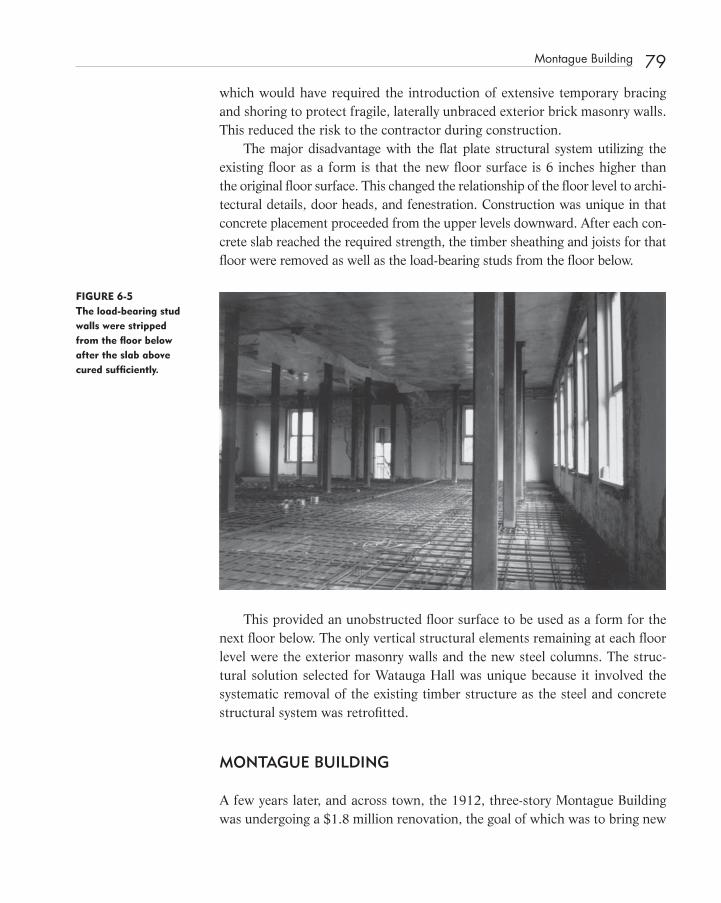
which would have required the introduction of extensive temporary bracing and shoring to protect fragile, laterally unbraced exterior brick masonry walls. This reduced the risk to the contractor during construction.
The major disadvantage with the fl at plate structural system utilizing the existing fl oor as a form is that the new fl oor surface is 6 inches higher than the original fl oor surface. This changed the relationship of the fl oor level to archi-tectural details, door heads, and fenestration. Construction was unique in that concrete placement proceeded from the upper levels downward. After each con-crete slab reached the required strength, the timber sheathing and joists for that fl oor were removed as well as the load - bearing studs from the fl oor below.
FIGURE 6-5 The load-bearing stud walls were stripped from the fl oor below after the slab above cured suffi ciently.
This provided an unobstructed fl oor surface to be used as a form for the next fl oor below. The only vertical structural elements remaining at each fl oor level were the exterior masonry walls and the new steel columns. The struc-tural solution selected for Watauga Hall was unique because it involved the systematic removal of the existing timber structure as the steel and concrete structural system was retrofi tted.
MONTAGUE BUILDING
A few years later, and across town, the 1912, three - story Montague Building was undergoing a $ 1.8 million renovation, the goal of which was to bring new
Montague Building 79
c06.indd 79c06.indd 79 12/18/08 10:11:34 PM12/18/08 10:11:34 PM

80 Watauga Hall and the Montague Building
life to a wood - framed offi ce building that had been vacant for at least 15 years. The Montague Building is on the National Register of Historic Places. Located in the central business district of Raleigh, it had been the subject of several architectural and engineering analyses during prior years because of the poten-tial value of leasible offi ce space in the rapidly growing Sunbelt city.
FIGURE 6-6 The south face of the Montague Building contained severely deteriorated brick masonry.
The three - story Montague Building was constructed in 1912. The fi rst fl oor was divided into six retail bays with storefronts on the north side. The upper two fl oors were, for the most part, offi ce space separated by a double - loaded central corridor. Architectural features included tin ceilings in all areas except the base-ment. Glass sidewalk prisms allowed natural light into the basement area on three sides of the building. The basement area extends to approximately 4 feet beyond the outside face of the building below the glass prism grates. The glass prisms on the north side had an unusual purple tint. The magnesium content of the glass prisms reacted with the ultraviolet rays in the sunlight to provide the purple color, according to information obtained from the Corning Glass Museum in Corning, New York.
The builder of the Montague Building, Benjamin F. Montague, built in a developing section of downtown Raleigh, near the new City Sanitary Farmers Market and Tabernacle Baptist Church on Moore Square. It never reached its potential as an income producing property because Mr. Montague could not fi nd enough satisfactory tenants.
c06.indd 80c06.indd 80 12/18/08 10:11:36 PM12/18/08 10:11:36 PM

The upper fl oors of the Montague Building were used as offi ce space until the 1950s. The lower retail bays were in use until the mid - 1960s. Insuffi cient egress and the absence of a sprinkler system and a fi re - rated fl oor system pre-vented the upper fl oors of the Montague Building from being used in more recent times.
MONTAGUE BUILDING STRUCTURAL SYSTEM REINFORCED
On February 14, 1986, we forwarded the following report to the developer of the Montague Building:
Based upon our observation on January 25, 1985, February 4, 1986, and sev-eral other times, we have performed a design analysis of the existing fl oor joists which frame the fl oor structure of the Montague Building.
The Montague Building structural system is a three - story timber post and beam structure consisting of 6 � 6 timber columns, 8 � 10 beams and 1 5 ⁄ 8” � 11 5 ⁄ 8 ” timber joists, 12 inches on center, which span 19 ’ - 6 ” between frames.
There is considerable deterioration of the structural system due to roof leaks. A fi re damaged a portion of the fl oor system in the basement area in the east end of the building.
Utilizing a dead load of 23 psf which includes the addition of one inch of Gypcrete topping, a sprinkler system, and a layer of sheetrock to the underside of the joists, it appears that the fl oor joists cannot safely support a live load of 50 psf in accordance with the 1978 edition of the NC State Building Code. Allowable live load for the fl oor joists was computed to be 36 psf.
We utilized a modulus of elasticity of 1400 ksi and an allowable bending stress of 1400 psi for repetitive member use in accordance with the tabulated design values for Southern pine as found in the 1982 edition of the National Design Specifi cation for Wood Construction. These values were modifi ed by the test results of Froehling and Robertson, Inc. report number RM66 - 079 date February 1985.
Froehling and Robertson ’ s geotechnical exploration and materials testing report indicates the following:
1. The basement fl oor slab is inadequate. The thickness of the basement fl oor slab is 3 / 4 to 1 ¼ inches. There is no vapor barrier beneath the slab.
2. The underlying soils are stiff, providing and allowable bearing capac-ity of 3,000 psf. The site is dry with the water table located probably at an elevation of 30 feet below grade.
Montague Building Structural System Reinforced 81
c06.indd 81c06.indd 81 12/18/08 10:11:37 PM12/18/08 10:11:37 PM

82 Watauga Hall and the Montague Building
3. Pull - out tests of masonry anchors indicate that the existing masonry is quite soft with a low bearing capacity. The condition of the south wall is critical. Masonry deterioration due to water damage and the number of large window openings combine to make the south wall a critical structural element.
4. The six timber joists tested indicate that the existing fl oor joists are equivalent to No. 2 southern pine except in defl ection.
Note that the following minimum uniformly distributed live loads will require reinforcement or replacement of the structure in certain areas:
Offi ce (fi xed partitions) 50 psf Offi ce (movable partitions) 80 psf
Retail, fi rst fl oor, 100 psf
Lobbies, offi ce buildings, 100 psf
Corridors, above fi rst fl oor, 80 psf
Business machine equipment, 100 psf
Library stack rooms, 150 psf
File Room, 80 psf
Rest Rooms, 60 psf Public Rooms, 100 psf
Also note that the 36 psf allowable live load for the Montague Building is less than most of the uniformly distributed live loads tabulated above.
As in many historic buildings, modifi cation to this structure will be neces-sitated by fi re code requirements as well as the inability of the structure to support minimum required design live loads in all fl oor areas. Joists, columns, and beams are all undersized for minimum offi ce occupancy live loads.
We have made a full exploration of options resulting from an in - depth investigation which, in the judgment of this engineer, justifi es structurally reconstructing the interior of the building.
After providing a detailed description of the new interior structural con-crete fl at - plate system that we proposed, we concluded our report with the following:
Reinforcement of the very defi cient structural system, in a building which has been vacated for 15 to 20 years, is a diffi cult, risky and costly endeavor. With no question, the existing structural system of the Montague Building should be replaced.
••
•
•
•
•
•
•
••
c06.indd 82c06.indd 82 12/18/08 10:11:37 PM12/18/08 10:11:37 PM

It is hoped that the recommended structural solution will be seriously considered during the evaluation for integrity by the United State Department of Interior and that the 25% tax credit status will be maintained. We would not want the issue of the loss of tax credits to affect what we believe to be our best judgment as professional engineers when that decision affects the life, health, and safety of the public.
In the Montague Building, this same system of fl at - plate concrete slabs and steel columns could have been used to an advantage in that the original note-worthy tin ceilings could have been reinstalled at their proper elevations, close to the existing window heads, while the space previously occupied by the fl oor-ing, subfl oor, and joists could have accommodated mechanical ducts. In order to accomplish this, the tin ceiling would be taken down, cleaned, paint primed, stored, and then reinstalled on a ceiling framing system suspended from the completed concrete fl oor structure above.
The original structural system for the Montague Building was a three - story post and beam structure consisting of 8 � 8 timber columns, 8 � 10 beams, and 2 � 12 timber joists, spaced at 12 inches on center. Considerable deterio-ration to the timber structural system was due to roof leaks and fi re damage.
Although I recommended the fl at - plate concrete structure with steel col-umns for the Montague Building, the developer argued that the replacement of the existing structure would jeopardize the 25 percent tax credit incentive for a certifi ed rehabilitation.
The reinforcement of the existing structure of the Montague Building for minimum offi ce occupancy live loads required the reinforcement of every joist and every fl oor beam. The fl oor beams were reinforced by applying steel side angles to the outside face of each member with hardened annular threaded, ring shank nails. Reinforcing the joists required the application of a composite metal cover plate to the underside of all joists. The design of this reinforcing was based on transformed section combining the wood joists with the steel cover plate acting in tension. To ensure composite action, the installation of the straps required the contractor to jack the joists above level and fasten the straps to the underside of the joists in a sequential and symmetrical manner starting from mid - span of the joists. The carpenters were less than happy, hav-ing to drive thousands of screws, overhead, into the underside of the joists using 1980s - era (very heavy) screw guns. Two types of screws were tested at the North Carolina State University Department of Wood and Paper Science Laboratory to obtain reliable design values in shear for the threaded fasteners. Thirteen assemblies were prepared using 14 gauge by 2 - inch - long slotted hex-head screws. Twelve specimens were assembled with 14 gauge by 1 ¾ - inch hexhead self - tapping screws. The specimens were fabricated by the general
Montague Building Structural System Reinforced 83
c06.indd 83c06.indd 83 12/18/08 10:11:38 PM12/18/08 10:11:38 PM

84 Watauga Hall and the Montague Building
contractor under jobsite conditions using wood samples from the Montague Building and then transported to the laboratory. The tapping screws were selected based on test results and ease of installation.
GEOTECHNICAL EVALUATIONS
Testing of the existing building components prior to design was a part of the structural assessment for both the Montague Building and Watauga Hall. Sub-surface evaluation at each building included test (or observation) pits dug by hand to establish footing depth and confi guration, hand auger borings, and test borings drilled with a truck mounted drill rig.
Geotechnical testing at Watauga Hall consisted of seven standard penetra-tion test borings drilled to a depth of 25 feet, one hand - auger boring drilled in the crawl space to a depth of 10 feet, and fi ve test pits dug around the perim-eter of the building.
With respect to underlying geology, both Watauga Hall and the Montague Building are located in the Piedmont physiographic province of Wake County, North Carolina. The in - place chemical weathering of the mica gneiss of the parent bedrock has produced an upper mantel of residual soils with clayey soils confi ned to the upper stratum.
For the Montague Building, a total of six hand - auger borings with dynamic cone penetration tests ranging 2 to 8 feet in depth were made in the basement area. Eight test pits were hand excavated to determine footing confi guration, elevation, dimensions, and soil consistence immediately below the footing base. To the exterior of the building, a truck - mounted drill rig was used to advance borings made in accordance with ASTM Specifi cation D - 1586 utiliz-ing a hollow stem auger. Soil samples were obtained with a split - barrel sam-pler driven to a depth of 18 inches or to a blow count of 100 blows with a 100 - pound hammer falling 30 inches. The standard penetration resistance N , denoting the number of blows per foot, is an indication of the in - place density strength and foundation support capacity. The soil samples were placed in glass jars, sealed, transported, and visually classifi ed in accordance with ASTM D - 2488.
In the basement, where access was prohibited to the truck - mounted drill-ing machine, hand augers were utilized. Handheld penetration testing was per-formed through the augured holes with a portable dynamic cone electrometer which utilizes a 15 - pound steel ring weight falling 20 inches on an “ E ” rod slide guide. The blows for 1 ¾ - inch increments were recorded. These cone resistance values were correlated to the standard penetration values to
c06.indd 84c06.indd 84 12/18/08 10:11:38 PM12/18/08 10:11:38 PM

determine the stiffness of the underlying soils. At the time, the use of the portable dynamic cone penetrometer had shown to be most reliable in four geologic regions, including the sandy or clayey sandy micaceous silts of the P iedmont geologic province of the southeastern United States.
In addition, relatively undisturbed soil samples were obtained by hydrauli-cally forcing sections of 3 - inch diameter, 16 - gauge steel, thin wall, or Shelby tube samplers into the soil at desired sampling levels. The samples were removed in the laboratory by a hydraulically operated extrusion press, meas-ured, sampled in accordance with ASTM D - 1587, “ Standard Method for Thin - Walled Tube Sampling of Soils. ” The tabulated laboratory test data for the various soil samples included the percentage of natural moisture, Atterberg limits, grain size analysis, the unifi ed soil classifi cation, and a cyclic shear stress versus strain curve for one sample.
I requested that the Raleigh offi ce of Froehling & Robertson, Inc. provide materials testing and geotechnical exploration for both Watauga Hall and the Montague Building. Included were geotechnical exploration as well as wood and masonry materials testing. The geotechnical exploration consisted of bor-ings, test pits, and laboratory analysis. The two geotechnical evaluations indi-cated that the Montague Building and Watauga Hall were both constructed on underlying soils that were stiff, providing a bearing capacity of 3,000 psf. Both sites were dry, with the water table located at an elevation of 30 feet or more below grade
TIMBER MATERIALS EVALUATION
Evaluation of the timber joists in the Montague Building required the sampling of six full - length joists selected at random. Field - obtained moisture meter read-ings were compared with the oven - dried moisture content measurements made in the laboratory on 4 - inch square samples in accordance with ASTM D - 2016. Tabulated data included specifi c gravity measured in accordance with ASTM D - 2395, annual timber growth rings per inch, of the slope of grain, unit weight of the timber samples, and cross - sectional dimensions of each sample.
The 2 � 12 timber joists were tested to failure in a laboratory utilizing a calibrated hydraulic jack that applied a concentrated load at the midpoint of an 11 - foot span. The load was applied in 500 - pound increments and defl ection was recorded to the nearest .001 of an inch utilizing an Ames Dial D efl ectometer.
Although the timber samples were visually classifi ed as one of the seven spe-cies of southern pine with a grade equal to a high quality No. 2, the test results indicated that the actual stiffness of this material was less than expected.
Timber Materials Evaluation 85
c06.indd 85c06.indd 85 12/18/08 10:11:39 PM12/18/08 10:11:39 PM
86 Watauga Hall and the Montague Building
The average modulus of elasticity of fi ve samples tested was 1,395,600 psi or approximately 7 percent less than the published modulus of elasticity used for No. 2 southern pine at the time the tests were conducted.
TAX CREDITS
The potential loss of historic integrity and the subsequent loss of tax credits in the latter stages of a project could prove disastrous to a developer. A structural engineer ’ s report should represent a full exploration of options for structurally reconstituting the building. In exercising professional judgment, the designers should consult with the reviewing agency to determine the acceptability of the various options as they relate to historically signifi cant features.
The tax status of the Montague Building was retained because the rein-forcement option was selected. It appears that if the preferred structural solu-tion for the Montague Building had been a suspended two - way concrete fl oor slab, the project would have been decertifi ed and not eligible for preservation tax incentives.
Although there is a need to develop methods of evaluating the probable service life of structural solutions, we must also be able to identify the other decision - making factors inherent in rehabilitating buildings.
Designers must walk a narrow path with regard to renovation options so as to not cause the decertifi cation of a historic property and the loss of tax credits. They must deal sensitively with the feeling of the building so as not to destroy the quality of the building that evokes an aesthetic or historic sense of a past period of time. This feeling may depend on the presence of surviving physical characteristics such as timber - framed fl oors or exposed roof trusses. Historic authenticity can be lost through extensive replacement of historic material and cannot be recaptured by reconstruction with new material in the rehabilitation.
The U.S. Department of Interior has issued interim guidelines for evaluating deteriorated building in order to amplify previously published National Park Service requirements and guidance for the Preservation Tax Incentives Program.
How will the serviceability of the reinforced Montague Building compare with the restructured Watauga Hall? The steel and concrete structure within Watauga Hall is a complete structural system supported by new column foot-ings, while the three - story reinforced wood frame of the Montague Building is supported on its original corbelled brick and rubble stone fi ll column footings and exterior brick masonry walls.
The Montague Building is an example of a project in which the original struc-tural system was reinforced in order to meet minimum design load requirements.
c06.indd 86c06.indd 86 12/18/08 10:11:39 PM12/18/08 10:11:39 PM

I proposed a solution similar to the successful fl at - plate system used for Watauga Hall, but it was rejected by the owner. The State Historic Preservation offi cer did not render a clear judgment with regard to the acceptability of the proposed con-crete fl oor system. Although the general contractor preferred the fl at - plate approach, suffi ciently accurate cost estimates of the two alternate systems were not generated prior to construction.
Clearly, our preservation philosophies need to recognize the potential lia-bility inherent in the diffi cult decisions made by design professionals such as structural engineers. Aesthetics weighs heavily in the decision - making process utilized by governmental agencies administering tax act preservation projects. A solution that requires the designer to reinforce a marginal timber structure, rather than replace the structure with a new system, involves additional risk to the owner, designer, and contractor.
The structural engineer is responsible for the structural adequacy for the renovated building through its service life no matter the solution. Rein-forcing a structure requires utilization of existing materials, which may not be reliable. The reinforcement of existing structures is more diffi cult, requir-ing innovative solutions. When the renovation of a building requires rein-forcing of the existing structure, adequate testing of the existing materials is critical.
Unfortunately, it is not always possible for the structural engineer to make the best decision with regard to future serviceability and building safety. Con-straints imposed by owners and lenders, eager to obtain tax credits, may sway an engineer toward the solution of meeting minimum code requirements for the short term. Success of an historic preservation project depends on many related and unrelated factors. The engineering judgment of the structural engi-neer should be given considerable weight in making decisions that affect the desired result.
Time will tell which solution was best. At the present time, Watauga Hall is fully occupied, limiting space to graduate - level students based on an applica-tion process. The Montague Building now houses Caf é Luna, several offi ces, and a branch offi ce of a large consulting engineering fi rm.
SUBSEQUENT FLAT - PLATE APPLICATIONS
I have recommended that use of the existing fl oor framing as a form to support a two - way cast - in - place fl at - plate system on fi ve occasions. We used it for the Garrett Hotel in Ahoskie, North Carolina, and more recently with great suc-cess at the Eagle Block Hotel in Newport, New Hampshire.
Subsequent Flat - Plate Applications 87
c06.indd 87c06.indd 87 12/18/08 10:11:39 PM12/18/08 10:11:39 PM

88 Watauga Hall and the Montague Building
The structural system utilizes the existing wood - framed fl oor structure as a form for a fl at - plate (two - way) concrete fl oor system. Steel - tube section col-umns on isolated spread footings support the concrete fl oor slabs. These are installed and braced prior to placement of concrete. Shear heads transfer the fl oor loads to the steel columns at each level. Cast - in - place perimeter angles connect the concrete fl oor slabs to the exterior masonry walls.
There are many advantages to this structural system for a renovation such as this. The most important advantage is that the existing fl oor system can be used as formwork. It is not necessary to deal with tall, unbraced masonry walls during construction.
The Concrete Reinforcing Steel Institute states the following advantages of a fl at - plate structural system:
The two - way fl at plate is one of the most effi cient structural systems for econ-omy. Flat plates can be constructed in minimum time with minimum fi eld labor because the fl at plate utilizes the simplest possible formwork and rein-forcing steel layout. Flat plates result in minimum story height for required clear headroom, and provide for most fl exibility in layout of columns, parti-tions, small openings, etc. Where job requirements permit direct application of the ceiling fi nish to the fl at plate soffi t, elimination of ceiling construction permits additional substantial cost and construction time savings compared to other structural systems. Flat plates have become increasingly economical and widely used as the cost of fi eld labor has increased relative to materials.
FIGURE 6-7 Floors were replaced in the Eagle Block (ca. 1835) in similar fashion to Watauga Hall. (See color insert.)
c06.indd 88c06.indd 88 12/18/08 10:11:40 PM12/18/08 10:11:40 PM
They have been applied with particular advantage to multi - story motel, hotel, hospital, dormitory, and apartment buildings 1
As in many historic buildings, modifi cation to the Eagle Block Hotel was necessitated by fi re code requirements, as well as the inability by the structure to support minimum required design live loads in certain areas.
There are many advantages of a solid two - way fl at - plate concrete fl oor system for the renovation of historic structures. The use of a fl at - plate system enables the contractor to utilize the existing fl oor framing and sheathing as formwork and existing load - bearing walls as shoring. Steps in this process would be as follows:
1. Remove of plaster and millwork from the interior stud walls and ceilings.
2. Construct interior column footings and erect new steel columns with shear heads through the existing fl oors.
3. Brace the steel columns and apply additional shoring and bracing to the formwork and original structure as needed.
4. Install continuous shelf angles with masonry and concrete tie systems between the perimeter of the fl at slab and the existing exterior masonry wall.
5. Place reinforcing steel on the upper level fl oor structure.
The process of setting reinforcing steel, and placing the slab, proceeds, by stages, downward until all levels are in place. At all times the structure is later-ally braced by existing or new fl oor systems. Removal of original vertical sup-ports proceeds from the top fl oor downward as each concrete slab above reaches suffi cient strength.
A fl at - plate system works well in historic buildings because of the short spans involved. A fl at - plate system gives considerable fl exibility to the contrac-tor with regard to actual fi eld dimensions that can be a problem when utilizing a framing system of shop - fabricated components. Rectangular or odd bays of varying dimensions can be easily accommodated. The advantages of pumped concrete can also be utilized. This will minimize the amount of vertical fl oor load transferred by the fl oor system to the existing walls by providing for can-tilevers wherever possible. Usually the use of a fl at - plate system eliminates the need for a fi re - rated ceiling or spray - on fi reproofi ng.
The south wall of the Eagle Block Hotel in Newport, New Hampshire, had a considerable bow in it that had been reinforced early in its history by bolting
Subsequent Flat - Plate Applications 89
c06.indd 89c06.indd 89 12/18/08 10:11:41 PM12/18/08 10:11:41 PM

90 Watauga Hall and the Montague Building
two channels to the outside face of the wall. We described how the steel and concrete system could be used to pull the south wall into alignment so that the existing reinforcing channels could be removed. When the contractor priced this operation as an add alternate of $ 150,000, it was very quickly deleted from the project by the developer as too costly.
In conclusion, the two - way fl at - plate system provides a structural system to accommodate the requirements of a modern building without the risk of working within an open masonry shell requiring considerable temporary brac-ing. This structural system will satisfy all fl oor live - load and fi re - separation requirements. The existing timber roof and attic framing systems can remain in place, as they did at the Eagle Block.
REFERENCE
1. Concrete Reinforcing Steel Institute (CRSI). CRSI Design Handbook , 9th ed. Schaumburg, IL: Concrete Reinforcing Steel Institute, 2002.
BIBLIOGRAPHY
Froehling & Robertson, Inc. , “ Subsurface Exploration & Materials Testing of Watauga Hall , ” Report #RJ66 - 179 , July 9, 1982 .
Froehling & Robertson, Inc. , “ Supplementary Report, Watauga Hall Renova-tion , ” July 23, 1982 .
Froehling & Robertson, Inc. , “ Geotechnical Exploration and Materials Testing of the Montague Building , ” Report #RM66 - 079 , February 11, 1985 .
Froehling & Robertson, Inc. , “ Tension Test, Restoration of the Montague Building , ” Report #RN66 - 195 , June 11, 1986 .
United States Department of the Interior, National Park Service, Interagency Resources and Reservation Assistance Divisions and Offi ce of the Solici-tor, “ Interim Guidance on Evaluating Damaged/Deteriorated Buildings in Registered Historic Districts for Purposes of the Preservation Tax Incen-tives Program . ”
U.S. Forest Products Laboratory , Wood Handbook: Wood as an Engineering Material , ( Washington, DC : USDA Agr. Handbk. 72, Rev. 1974 ).
c06.indd 90c06.indd 90 12/18/08 10:11:42 PM12/18/08 10:11:42 PM

91
C H A P T E R 7 The Restoration of St. Helena ’ s Church
T T he restoration of St. Helena ’ s Episcopal Church in Beaufort, South Carolina (1724), grew out of a preliminary structural evaluation we
provided regarding the deterioration of one end of one queenpost roof truss. The deterioration occurred next to a sidewall chimney fl ue, which penetrated the roof.
A leak in the vicinity of this roof penetration caused severe deterioration to the heel of one of the roof trusses where the top and bottom chords engage each other at the sidewall bearing point. Shortly after the completion of the structural report regarding the roof truss, George T. Fore, Materials Conserva-tor of Raleigh, North Carolina, was engaged by the vestry to study the exterior of the church.
Concerns raised in George Fore ’ s November 1994 “ Conditions Analysis and Conservation Studies ” report became the focus of additional study and debate. 1 They included a question regarding settlement of the sidewalls due to the bearing capacity of the underlying soils. Planned repair of the roof trusses based on the 1993 study needed to be expanded to include repairs to individual truss connec-tions in other locations and the lateral support of some individual truss members that had bowed out of alignment.
c07.indd 91c07.indd 91 12/18/08 10:12:16 PM12/18/08 10:12:16 PM
Structural Investigation of Historic Buildings: A Case Study Guide to Preservation Technology for Buildings,Bridges, Towers, and Mills. David. C. Fischetti © 2009 John Wiley & Sons, Inc.

92 The Restoration of St. Helena’s Church
Fore pointed out that tower work including repair of millwork, the bell support frame, and miscellaneous bracing of several elements was also required. Replacement of the Portland cement stucco at the base of exterior walls with a lime based stucco was identifi ed in the Fore report as a task sensitive to seasonal changes in temperature. Stucco repairs required in areas affected by structural repairs to the truss would be a part of the stucco portion of a large construction contract anticipated by the vestry.
In 1997, we provided a more thorough structural evaluation of the masonry and timber structure, including tabby foundations, balcony, framing, steeple, and roof structure, based on information obtained on April 7 and 8, 1997. We also included additional fi ndings based on our inspection with George Fore in August 1994 and our previous work in 1993 with regard to the roof trusses. We described repairs that emphasized the use of traditional materials compati-ble with the original construction. In this way, the interaction of dissimilar materials would not be an issue. We pointed out that the use of reinforced con-crete, structural steel, and epoxy - reinforcing methods have all been shown to result in less than perfect structural systems when combined with timber, brick masonry, and lime - based stuccos and mortars. By utilizing traditional materi-als, a certain sensitivity is achieved that is more in the spirit of The Secretary of the Interior ’ s Standards for Rehabilitation and Guidelines for Rehabilitating
FIGURE 7 - 1 The end of one queenpost truss was badly deteriorated.
c07.indd 92c07.indd 92 12/18/08 10:12:17 PM12/18/08 10:12:17 PM

Historic Buildings. We argued that building systems such as St. Helena ’ s Church can be made structurally sound by applying the usual engineering prin-ciples to those materials and the existing building geometry.
DESCRIPTION
St. Helena ’ s Episcopal Church is a building with a timber - framed roof, balcony, and second - fl oor level supported on load - bearing brick masonry exterior walls and interior timber columns. The main fl oor is framed with joists that run across in the transverse direction. The major expansions to the original 1724 building was an 1817 reconstruction of the sanctuary in brick and a large side balcony expansion in 1842, which included sidewalls, balconies, and a new roof structure, resulting in a sanctuary plan approximately 66 feet square with projections at each end for a narthex and sacristy. The steeple was rebuilt in 1940. A steel structural system was added to the steeple at that time. The underframing and platforms of the side balconies were reworked in 1969 to accommodate air - conditioning ducts.
OBSERVATION
In August 1994 we measured a relative humidity of 72.3 percent and a tempera-ture of 76.3 ̊ F inside the church at the balcony level. The principle balcony beams 8 by 11 inches in size had a moisture content of 10 percent. We observed the fram-ing of the bell tower and revisited the attic to observe the condition of the queen-post trusses. We observed the condition of the steel beam above the choir loft.
ROOF TRUSSES
The condition of the roof - framing system had not changed since our previous inspection.
We concentrated our efforts in determining the condition of the exterior load - bearing walls that supported the balconies and roof trusses. We verifi ed overall dimensions and wall thickness. It was determined that, based on mar-riage marks, the truss numbers ran from I to VI. Upon closer examination, it appeared that the roof trusses had suffered some recent wind damage. Besides the repairs to truss number IV, which had a deteriorated bottom chord, there were other members and connections that deserved attention.
Roof Trusses 93
c07.indd 93c07.indd 93 12/18/08 10:12:19 PM12/18/08 10:12:19 PM

94 The Restoration of St. Helena’s Church
BALCONIES
In August 1994, with Mr. B.J. Pinckney of the church, George Fore and I opened the sidewall balcony framing for observation by removing some boards. We were able to observe the condition of the bearing seat at the upper end of the balcony framing beams.
The principal framing of the balconies consisted of sloped 8 - inch by 11 - inch timbers that ran from the interior columns to the exterior wall where they rested on a 10 ¼ - by 10 ½ - inch sill plate supported and enveloped by the exterior wall. The exterior sidewalls had deformed outward over time. The maximum move-ment was at the balcony sill beam level. George Fore ’ s report showed that the maximum horizontal deformation of the wall was 2 5⁄8 inches on the north side and 3 9⁄16 inches on the south side. A horizontal crack had formed that ran along the full length of the sidewall, except at the ends where the masonry was tied back into the corners of the building.
The great concern with regard to the adequacy of the balconies was based on the deformation shown in George Fore ’ s report. Two disturbing possibilities were put forward by others regarding this movement. First, the underlying soils might be overstressed, allowing the sidewalls to settle and rotate about the toe of the footing.
This appeared to be a possibility because of the settlement observed in the fl oor joists and the door openings in endwalls, which had deformed into a
FIGURE 7-2 At this time the roof structure appeared unchanged from our previous visit.
c07.indd 94c07.indd 94 12/18/08 10:12:19 PM12/18/08 10:12:19 PM

FIGURE 7-3 The balcony framing was exposed for additional examination.
FIGURE 7-4 The horizontal cracks in the sidewalls had been patched many times.
parallelogram shape indicating movement of the sides of the nave down in a vertical direction. The second explanation was that the sloping balconies themselves were exerting pressure on the exterior walls, causing them to crack at the balcony level and forcing the now - hinged wall to rotate outward. A sloped end condition would tend to push the exterior wall outward because
Balconies 95
c07.indd 95c07.indd 95 12/18/08 10:12:20 PM12/18/08 10:12:20 PM

96 The Restoration of St. Helena’s Church
there would be a horizontal component of the beam reaction normal to the bearing surface.
The masonry wall is 27 inches thick below the balcony sill beam. If the beam was installed green, shrinkage would have occurred across the grain as much as a quarter of an inch. A small amount of shrinkage at the sill could act as a notch, causing a hinged effect in the masonry wall. The eccentricity of the notch, combined with rotation at the top of the wall due to truss defection, would be suffi cient to cause the amount of rotation that was observed in the wall. This, I determined, was the principal mechanism causing the balcony wings to rotate away from the building. It was signifi cant that the horizontal crack is located at the thinnest portion of the masonry wall at the top of the sill beam.
FIGURE 7-5 The sidewalls appeared to have settled, although diagonal settlement cracks were not visible.
c07.indd 96c07.indd 96 12/18/08 10:12:23 PM12/18/08 10:12:23 PM

One of the two balcony beams observed had a sloped bearing surface at upper end rather than a horizontally cut seat. The stucco at the “ hinge ” in the exterior wall had been patched several times. This indicated that the move-ment of the wall had been progressive over time.
In the computer, the north and south sidewalls were modeled as an inte-gral part of the building cross - section. We utilized a low modulus of elasticity of 350,000 psi for the brick masonry. Assumed allowable design values for the masonry are as follows:
Compressive strength, 56 psi Bearing, 100 psi Shear, 9 psi
The 12 - foot spacing of the building cross - section modeled in the computer included one roof truss, a bay of balcony framing, and the masonry sidewalls with window openings.
Overall building stability in the cross - section appeared tenuous, except for the balcony acting as a deep horizontal beam fastened to the endwalls. In the analysis we included the horizontal contribution of the balcony as a spring sup-port based on the stiffness of the plywood sheathing on the balcony steps. There was evidence that the balcony, with its considerable plywood sheathing,
•••
FIGURE 7-6 The 10 � 10 sills embedded in the masonry sidewalls were somewhat decayed.
Balconies 97
c07.indd 97c07.indd 97 12/18/08 10:12:24 PM12/18/08 10:12:24 PM

98 The Restoration of St. Helena’s Church
was performing well in that there was no cracking of the plaster ceiling under the balcony. Of course, all of the lateral loads applied to the sidewalls needed to be resolved through the balcony sheathing, roof sheathing, and ceiling fram-ing into the endwalls of the nave.
I argued that through jacking, the exterior wall could be forced back into alignment. In order to do this, both the balcony and roof loads would have to be temporarily relieved and the sidewall temporarily braced. All mortar joints that had opened over time and have been fi lled, in the vicinity of the fold, would have to be raked out in order to reverse the alignment. The gap above the balcony sill would have to be fi lled and the end of the balcony beam fl at cut, blocked, or tied in where the sloped bearing conditions exist. The balcony sill beam would have to be replaced where deteriorated, with a dry timber that would not shrink over time.
TOWER
The tower was rebuilt in 1940 in accordance with architectural drawings by architect Albert Simmons of Charleston. The 1940 architectural tracings (drawings) for the tower were stored in the Fireproof Building in Charleston in fl at fi les. The tower as built included wood siding on diagonal sheathing on wood studs attached to a steel framing system.
FIGURE 7-7 The bell tower was reframed in 1940 with wood on a steel frame.
c07.indd 98c07.indd 98 12/18/08 10:12:25 PM12/18/08 10:12:25 PM

The steel frame provided great rigidity to the steeple up to the transition level where the framing changes to timber. The bell support system appeared to be much older than the 1940s work. The new tower structure was apparently designed to accommodate the geometry of the bell and its framing system.
The lantern and spire sections were framed in timber in a confi guration similar to St. Michael ’ s in Charleston. The west side of the tower rested on two cast - in - place concrete blocks supported by the original west wall. The east side of the tower rested on a 30 - inch - deep steel beam that spanned the masonry opening between the narthex and the nave.
Critical to the bell tower were loading conditions that included north - south wind, which would tend to place unbalanced loads onto the supporting wall or the W30 beam. Wind in the east - west direction would impose the great-est total load on the 30 - inch - deep steel beam.
In the computer analysis of the tower, we applied a 120 mph wind in accord-ance with ASCE - 7, except that a shape factor of 0.8 was used for the spire and lantern levels. The bell and bell frame were included as a 1,500 - pound load. The analysis was performed in the north - south and east - west directions.
The calculations indicated that the steel structure was rigid and that most of the movement in the spire is a result of the open lantern level. Diagonal sheathing was simulated in the timber - framed portion of the steeple to provide a reasonable amount of rigidity. A theoretical defl ection of 4 ½ inches at the top of the spire was calculated with these assumptions. The 30 - inch - deep steel beam, steel tower legs, and the steel cross - bracing appeared to be adequate in size. Critical to the performance of the steeple in a 120 mph wind load was its anchorage to the top of the outside wall and the anchorage of the 30 - inch - deep steel beam to the inside wall on either side of the choir loft. The 22,000 pounds of resistance to hold the steeple legs down could be achieved by assuring that the tie - down points contained a minimum of 150 cubic feet of concrete, or 225 cubic feet of brick masonry. The bearing pressures at all support points were adequate as long as each location has 240 square inches of contact against the brick. The uplift capacity of the steeple could be enhanced by rebuilding the beam and tower bearing points with a compatible but harder brick rather than concrete and facilitating a tie that engages at least 225 cubic feet of masonry.
CHURCH GARDEN WALL
The church property is surrounded by a brick wall that defi nes the perimeter of the block that contains the sanctuary and churchyard. This free - standing brick wall contains portions built at various times. Differences in grade causing
Church Garden Wall 99
c07.indd 99c07.indd 99 12/18/08 10:12:26 PM12/18/08 10:12:26 PM

lateral earth pressure and pressure from trees have pushed the wall out of alignment. The wall contains settlement and temperature cracks, as well as shear cracks at various locations. At the time of our inspection, mortar was missing or deteriorated in areas, and bricks were deteriorated, broken, or miss-ing. Unsuitable repairs with Portland cement mortar and stucco had been made. We recommended that a tree survey that notes not only species, size, condition, and location, but also location in regard to present or potential dam-age to the church wall or monuments be undertaken. This would require the services of an architect, landscape architect, structural engineer, and materials conservator working together. The condition of the garden wall varied greatly along its length and required various types of repairs.
MASONRY
The masonry of the existing walls of the church consisted of a lime - based mortar and oversized bricks. The bricks appeared to be of medium hardness and the mor-tar medium to soft. The interior plaster and exterior stucco served to provide a fi n-ish, while protecting the wall on the exterior from the weather. Historic walls with plaster on the inside surface tend to provide better service than unplastered walls. In an unplastered wall, mortar joints tend to deteriorate at a more rapid rate with a loss of bond within the lime mortar causing the sand component to spill from the joints. Obviously, even with deterioration of mortar joints in a plastered wall, the sand component would be contained. Deterioration in a masonry wall with a plaster fi nish will eventually be obvious, as the plaster will crack and sepa-rate from the face of the brick wall as the wall disintegrates. In contrast, at St. Helena ’ s we had a building in which the existing interior plaster was well bonded to the brick walls except at a few notable locations. The service life of lime - based mortar in historic walls is dependent on the structure remaining relatively dry. The roof of St. Helena ’ s had been well maintained, and the crawl space was dry. The soil beneath St. Helena ’ s consisted of well - drained light gray or brown sands and clayey sands. In August 1995, S & ME, a geotechnical fi rm from Mt. Pleasant, South Caro-lina, reported that the water table was at 15 feet below the ground surface.
Historic lime - based masonry walls can be reinforced after construction by installing pencil rod or all thread rods reinforcing into horizontal masonry joints during deep repointing. In this manner, common thermal stress cracks can be “ stitched ” back together at locations such as above the numerous window open-ings in St. Helena ’ s. Such stitch reinforcing, although disruptive to walls cov-ered with plaster or stucco, work well in repairing cracks in masonry walls that have been troublesome for many years.
100 The Restoration of St. Helena’s Church
c07.indd 100c07.indd 100 12/18/08 10:12:27 PM12/18/08 10:12:27 PM

In the past, we have also applied metal lath to historic masonry walls as a reinforcing procedure, which when plastered, acts to seal the mortar joints from extremes in moisture and temperature. The wall over the Chancel arch at St. Philip’s in Charleston was treated in this manner. Besides serving to struc-turally tie the wall together and bridge cracks, this system provides a “ tell - tale ” system to indicate future movement in the wall. The inside faces of the interior walls of one wing of the circa 1903 Kivett Hall at Campbell University, in Buie ’ s Creek, North Carolina, were covered with metal lath and plaster in 1976. During a recent inspection, no cracks were observed in these walls, which con-sisted of interior wythes of very soft brick and lime mortar.
The large cracks in the endwalls of the nave of St. Helena ’ s Church resulted from an inadequate masonry tie between sections of walls built at various times.
FIGURE 7-8 Very little bonding connected walls built at various times.
The large cracks beneath the 30 - inch - deep steel beam were the result of just such a discontinuity due to faulty construction. To properly “ tooth ” a wall together requires that the original and new bricks match in size, that the addi-tion courses with the original, and that suffi cient skill and effort is expended to ensure that as many of the original bricks are engaged by the new brickwork.
In the large crack that was exposed between the walls constructed at dif-ferent times, only one tie brick was observed. The joint between wall sections was quite wide, indicating that the tendency of the balconies to move outward
Masonry 101
c07.indd 101c07.indd 101 12/18/08 10:12:27 PM12/18/08 10:12:27 PM

could not be restrained across the joint. The wildly random coursing of the brick in the two sections of wall could be corrected by reworking a suffi cient width of masonry to obtain coursing, or by stitching across the crack with joint reinforcing.
The clay tile in the east and west gable walls of the attic obviously did not course with previous brick masonry when used to rebuild gable ends blown out by a storm.
FIGURE 7-9 The gable walls were rebuilt in 1940 with clay tile instead of brick masonry.
This material was used because it is light, economical, and a popular method of construction in the 1940s. We recommended that the clay tile be replaced with brick units to match the original in size.
PLASTER AND STUCCO
Traditional plaster and stucco applied to brick masonry is an excellent “ tell - tale ” system for crack evaluation. Any discontinuity or crack that causes move-ment will telegraph through the plaster or stucco system. The history of a crack can be determined by observing its progression in historic photographs and evaluating the materials used as crack fi llers in the past. The fi ne cracks in the sidewalls above the windows were, for the most part, thermal in nature, typical
102 The Restoration of St. Helena’s Church
c07.indd 102c07.indd 102 12/18/08 10:12:28 PM12/18/08 10:12:28 PM

of cracks in eighteenth and nineteenth century un - reinforced brick masonry walls with large window openings. Most of the sidewall cracks in St. Helena ’ s were thin hairline cracks. They were observed to be running in a vertical direc-tion usually above or near window head locations. These cracks were located above most of the windows in the sidewalls of the nave.
TABBY
Tabby is an early cast - in - place construction material consisting of sand, lime (from shells and wood ash), and water. The foundations of the 1842 addition to St. Helena ’ s consist of a 26 - inch - deep unreinforced footing of tabby on which rested the brick masonry walls. The original foundation walls are of brick con-struction extending to a greater depth than the foundations of the addition.
Because of its relatively low strength, tabby performs well when uniformly loaded. The support of a post or beam is problematic when concentrated loads are not distributed such as on a wood plate or brick masonry - bearing block. The computed design pressure for the combined dead load and live load of 6.8 psi was low when compared to the 350 psi compressive strength obtained by Sickels - Taves. In St. Helena ’ s we had a fairly uniform load. There were no cracks in the sidewalls related to settlement caused by failure in the tabby.
SUBSURFACE EVALUATION
To determine the nature and consistency of underlying soils in the vicinity of the exterior wall, in 1994 we requested that the S & ME offi ce in Charleston provide a proposal to the church for a geotechnical investigation and analysis consisting of borings, small test pits and laboratory analysis. S & ME ’ s proposal was accepted and fi eld exploration occurred in August of 1995. The purpose of the soils inves-tigation was to determine the amount of settlement that had occurred, its cause, and how much future settlement was anticipated. We also wanted to determine the probable response of the underlying soils during a seismic event.
S & ME ’ s subsurface exploration Report No. 1131 - 95 - 034 dated August 18, 1995, presented the results of the exploration and analysis. We were in contact with Billy Camp, P.E. of S & ME, during this procedure and also con-sulted with George Fore prior to, and after, obtaining the results from S & ME.
The purpose of the exploration work was to determine the nature and con-sistency of the soils directly below the balcony sidewalls of the church and the confi guration of the wall at the bearing elevation. It was thought by others that this might explain the outward rotation of the walls. The question of whether
Subsurface Evaluation 103
c07.indd 103c07.indd 103 12/18/08 10:12:30 PM12/18/08 10:12:30 PM

the movement was due to settlement or rotation in loose or unconsolidated soils was important to answer because foundation underpinning solutions are very expensive.
The results of the settlement analysis indicated that the supporting soils are sands that are relatively dense. Settlement occurred during construction as load was gradually applied. The report concluded that there is no reason to believe that the foundation soils have caused ongoing settlement. In the report, S & ME proposed that a 1,500 psf allowable bearing pressure be used for design. This compared well with the calculated wall loads.
At this point, we discarded underpinning as a part of the work. Monitoring was recommended to study the problem further. The results of a monitoring pro-gram would indicate whether the movement shows seasonal fl uctuations due to temperature or moisture changes. This would determine how active the hinge point was.
The crack and wall movement was an indication of a problem. As long as the balcony remained attached, there was no danger of collapse due to vertical loads. The weakened (open) horizontal joint was a possible problem with regard to high wind forces acting outward on the exterior wall.
SEISMIC ANALYSIS
Previous comments by other structural engineers had raised the level of con-cern in the congregation with regard to seismic safety. As a result of those dis-cussions, we included in the evaluation report a rather extensive discussion of seismic issues affecting St. Helena ’ s.
We insisted that several broad questions be asked before we would recom-mend or adopt a complicated or excessive seismic mitigation. First, what is the risk of injury, death, or property damage in Beaufort due to a seismic event? Second, how much would seismic provisions add to the cost of rehabilitating St. Helena ’ s? Third, what were the current requirements of the state and fed-eral building codes with regard to seismic reinforcing and repairs to historic structures?
From this, it was apparent that the risk of death or injury in a seismic event for a person in St. Helena ’ s Church is extremely small. Although the building code required that higher seismic factors be used when reviewing an assembly type building such as St. Helena ’ s, which seats 300 or more people in one room, in reality the building is fully occupied for only a very few hours each week. As part of the geotechnical analysis, we asked S & ME to review the
104 The Restoration of St. Helena’s Church
c07.indd 104c07.indd 104 12/18/08 10:12:30 PM12/18/08 10:12:30 PM
potential for the liquefaction of the soils underlying St. Helena ’ s in a seismic event because the greatest amount of damage is often caused by the subsid-ence of masonry buildings on soils as occurred in Kobe, Japan, and in nearby Charleston in 1886.
To enhance the wind and seismic capacity of St. Helena ’ s, the exterior walls could be rehabilitated by repairing cracks. The balcony fl oor and roof framing had to be securely anchored to the exterior walls. Repairs had to include a posi-tive anchorage to all of the exterior walls in accordance with the “ Bolts - Plus ” philosophy of seismic reinforcing. This method of seismic reinforcing relies on traditional methods to tie building elements together. The seismic (and wind) resistance of a building can be greatly enhanced by simply providing a positive connection between the fl oor and roof framing and the exterior walls. The earthquake anchor, developed in Charleston as a result of the 1886 earthquake, is an example of a “ Bolts - Plus ” type seismic repair. For “ Bolts - Plus ” to work, we insisted that deteriorated masonry and timber be repaired.
LIQUEFACTION
Liquefaction, the loss of a soil ’ s shear strength due to the increase in water pore pressure resulting from seismic vibrations, is always a concern in the Charleston area. Liquefi able soils are commonly found in South Carolina, and much of the geological evidence suggests that liquefaction has occurred during past earthquakes. The potential for liquefaction depends on the nature of the soils, groundwater potential, and the magnitude of the earthquake. Using standard methods of analyzing liquefaction, based on the seismic risk of the Beaufort area, the probability of liquefaction or the liquefaction potential for a given exposure time can be predicted. The amount of ground settlement due to liquefaction can also be predicted.
The S & ME report indicated that assuming an earthquake magnitude of about 5.9 and a base acceleration of 0 to 12g, the liquefaction potential of the underlying soils beneath St. Helena ’ s was within acceptable limits.
Based on the above assumptions, factors of safety against liquefaction were calculated for the potentially liquefi able deposits. Standard Penetration data ( N values) from the soil test borings indicated that the factors of safety were greater than 1.5 and, consequently, the risk of liquefaction would be acceptable by today ’ s standards. The report concluded that some densifi cation of the loose sands above the water table, and therefore settlement, could occur during an earthquake even without liquefaction.
Liquefaction 105
c07.indd 105c07.indd 105 12/18/08 10:12:30 PM12/18/08 10:12:30 PM

The liquefaction potential can be reduced in one of six ways: base isolation, deep foundations, drainage wells, chemical grouting, jet grouting, or compac-tion grouting. These methods range in cost from the most expensive to the least expensive. The fi rst two are structural modifi cations to the foundation of the building; the others affect the subsoils. At that time, recent experience from the West Coast indicated that seismic events varied to such a degree that predicting the response of a building that has been modifi ed or that rests on remedied soils was almost impossible.
Since the costs for mediation were high and the benefi ts unpredictable, a reasonable solution was to not do anything if the potential for liquefaction and the amount of settlement was determined to be tolerable. Damage from a major seismic event can be controlled by ensuring that wall and fl oor systems are tied together and masonry is contained and reinforced. In this manner, set-tlement due to liquefaction can be tolerated and structural stability does not depend on soils mediation or foundation modifi cation. In fact, the summary of S & ME ’ s report concluded that the underlying soils were resistant to liquefac-tion, and that modifi cation to the foundation was not necessary.
Based on the soil conditions encountered at the site, there was no reason to believe that the foundation soils were settling. However, settlement would be expected if the foundation loads or soil stresses were increased. Conse-quently, from a geotechnical standpoint, ground modifi cation or foundation underpinning was not necessary.
RECOMMENDATIONS
Based on our analysis, and by applying engineering judgment relating to other historic structures such as St. Helena ’ s, we offered the following recommenda-tions for the building committee and vestry to consider:
The sidewalls of the building should be jacked into a vertical alignment and the masonry reworked, reducing the eccentricity of the wall and increasing the net section of the masonry at the critical juncture with the balcony while reestablishing vertical continuity. At the same time, the bal-conies should be securely tied into the masonry sidewalls in a manner often referred to as “ bolts - plus ” reinforcing. This will require the instal-lation of a new balcony header sill in accordance with sketches enclosed with our report. Roof truss number IV should be repaired by replacing the deteriorated lower chord. This will require the shoring of the curved plaster ceiling
•
•
106 The Restoration of St. Helena’s Church
c07.indd 106c07.indd 106 12/18/08 10:12:31 PM12/18/08 10:12:31 PM

and ceiling framing. Other repairs are required to individual truss joints and members. Additional bracing should be applied to the ceil-ing structure to tie the roof structure into the endwalls. Lateral bracing added to the top chord of the trusses will greatly increase their capacity to resist buckling.
The bell tower will require miscellaneous repairs to various items, such as the bell support frame. A proper paint restoration specifi ca-tion should be followed to renew the exterior millwork and siding, which is very important in protecting the structural system of steel and wood. To properly anchor the tower will require the reworking of the two concrete - bearing blocks at the corner of the front wall and at the bearing of the 30 - inch - deep steel beam. Suffi cient masonry should be reworked to ensure that an adequate amount of masonry is engaged with an anchor bolt tie to prevent the overturning of the tower by strong winds. The greatest portion of the work will involve masonry restoration by rebuilding and reinforcing weakened or inadequate sections of wall. A masonry restoration and repair program consisting of compatible brick units and lime mortar should be implemented to repair the joints in the endwalls and the horizontal balcony level joints in the sidewalls. Minor temperature cracks should be stitch reinforced.
In summary, the following items of work were required to structurally sta-bilize St. Helena ’ s Church. All of these tasks were completed, resulting in a structural shell and building envelope that should provide continued service for many years:
Protect interior plaster work. Shore the roof structure.
Use cribbing temporarily to support balcony.
Make timber repairs to the roof trusses.
Laterally brace sidewalls.
Replace the balcony sill plate.
Jack balconies, sidewalls.
Repair masonry and stucco at sidewall cracks.
Rework brick at endwall cracks.
Repoint the brick masonry . Paint exterior at steeple.
•
•
••
•
•
•
•
•
•
•
••
Recommendations 107
c07.indd 107c07.indd 107 12/18/08 10:12:31 PM12/18/08 10:12:31 PM

FIGURE 7-10 Lateral bracing consisting of timber poles and framing was installed on both sidewalls. (See color insert.)
FIGURE 7-11 Great care was taken to protect the monuments in the church yard.
108 The Restoration of St. Helena’s Church
c07.indd 108c07.indd 108 12/18/08 10:12:31 PM12/18/08 10:12:31 PM

FIGURE 7-12 JR Graton provided much of the labor required to build and set the temporary lateral bracing.
In fact, the project included several other work components, resulting in a comprehensive and coordinated project that was bid in the traditional manner. These other work items included rebuilding the fl oor of the narthex, anchoring the supports of the steeple to resist wind forces, and providing a lateral bracing system in the attic to ensure resistance to wind acting in the transverse direc-tion across the sanctuary.
The general contractor for the renovations to St. Helena ’ s Episcopal Church was Ruscon of Charleston, South Carolina. Their bid was based on a set of architectural and structural drawings compiled by architect J. Stephen Smith of Camden, South Carolina. When it was apparent that the building could be fi xed by pulling the sidewalls inward to a plumb position, I recom-mended that the church contact Arnold M. Graton, Master Bridgewright (of covered bridges), who was engaged at the time rebuilding the Auchumpkee Creek Covered Bridge in Thomaston, Georgia, which had been destroyed in a fl ood. After a visit to Georgia to meet Arnold, the building committee stipu-lated that Ruscon include Arnold M. Graton & Associates as the subcontractor to perform this work.
Temporary vertical supports of 6 � 8 spruce cribbing were installed inside the church, through the balconies, to support the roof.
The sidewalls were laterally supported by braced timber frames, placed on the outside of the building, and the sidewalls were gently and carefully pulled
Recommendations 109
c07.indd 109c07.indd 109 12/18/08 10:12:34 PM12/18/08 10:12:34 PM

FIGURE 7-13 Cribbing consisted of 6 � 7 (actual dimension) by 4-foot-long eastern white spruce.
FIGURE 7-14 The timber frames were used to stabilize the sidewalls during the straightening operation.
inward using a large number of Griphoists ® (cable ties with come - alongs) placed across the sanctuary.
Arnold Graton secured the Griphoists ® to timber framing secured to the outside of the sidewalls.
110 The Restoration of St. Helena’s Church
c07.indd 110c07.indd 110 12/18/08 10:12:35 PM12/18/08 10:12:35 PM

FIGURE 7-15 Griphoists® were used to pull the sidewalls together.
FIGURE 7-16 The Griphoists® were secured to timbers that straddled the window openings.
The renovation of St. Helena ’ s Episcopal Church won a 2001 South Carolina Honor Award by the Palmetto Trust for Historic Preservation.
Recommendations 111
c07.indd 111c07.indd 111 12/18/08 10:12:37 PM12/18/08 10:12:37 PM

FIGURE 7-17 The completed project won an award from The Palmetto Trust for Historic Preservation.
FIGURE 7-18 The underside of the side balconies were replastered.
112 The Restoration of St. Helena’s Church
c07.indd 112c07.indd 112 12/18/08 10:12:40 PM12/18/08 10:12:40 PM

FIGURE 7-19 All exterior surfaces were renewed, including the steeple. (See color insert.)
REFERENCE
1. George Fore ’ s November 1994 “ Conditions Analysis and Conservation Studies ” report
Reference 113
c07.indd 113c07.indd 113 12/18/08 10:12:42 PM12/18/08 10:12:42 PM

115
C H A P T E R 8 Market Hall Rehabilitation
N Not only did Charleston ’ s 1841 Market Hall survive war, tornados, hurri-canes, fi re, and the 1886 earthquake, but also it suffered underutilization
and neglect forced by Reconstruction and the Depression that hit South Carolina ’ s economy especially hard. During the bombardment of the city from Morris Island by federal forces, an artillery shell burst through the roof, graz-ing the bottom chord of one kingpost roof truss.
Damage by historic events such as the Civil War and the 1886 earthquake, combined with the low country ’ s harsh climate of sun, rain, and humidity, were abundantly evident when Phillips & Oppermann, PA obtained the architec-tural design contract for its restoration in 1992.
This chapter will relate the design team ’ s struggle to apply conservation prin-ciples by integrating high - tech solutions of analysis and materials testing with simple traditional approaches of timber framing and masonry restoration.
Once the strategy for structural rehabilitation was developed, it had to be defended on several occasions prior to the start of construction and through a construction period that lasted more than three years. Major items of discussion were shoring and bracing, masonry rehabilitation, and timber framing. Although Charleston, being a port city, is hardly isolated, much of the expertise for the rehabilitation was obtained at a distance from the project. The Winston - Salem – based architect Joseph K. Oppermann assembled a team consisting of a struc-tural engineer, materials conservator, and a mechanical engineer from such diverse locations as Raleigh, North Carolina; Philadelphia, Pennsylvania; and East Norwalk, Connecticut.
c08.indd 115c08.indd 115 12/18/08 10:13:27 PM12/18/08 10:13:27 PM
Structural Investigation of Historic Buildings: A Case Study Guide to Preservation Technology for Buildings,Bridges, Towers, and Mills. David. C. Fischetti © 2009 John Wiley & Sons, Inc.

116 Market Hall Rehabilitation
The structural engineer ’ s decision to pull the fl oor structure out and reha-bilitate timber - bearing pockets was a much - debated issue. To enhance Market Hall ’ s resistance to wind and seismic forces, the design strategy called for the existing fl ooring to be temporarily removed and the fl oor joists lifted out to be rehabilitated or replaced. A diagonal subfl oor consisting of 5/4 sheathing boards was specifi ed to be installed between the original joists and fl ooring forming a structural diaphragm. Both shear and axial forces had to be trans-ferred between the two elements of wall and fl oor.
The number of fl oor joists requiring replacement or rehabilitation was a question of debate. I insisted that the contractor ’ s carpenters could best make that determination after the joists were pulled out and examined. The contractor wanted, in advance, to be provided with the exact number of timbers to order.
Much of the masonry had to be rebuilt with loose bricks pulled out and relaid. The masonry restoration contractor questioned the scope of the work after their bid proposal was accepted.
Construction management issues such as these greatly impacted the over-all preservation plan. A diverse team of designers led an extensive construction team through a diffi cult rehabilitation tempered by constraints inherent in municipal capital projects. Through friendly persuasion, the design team ulti-mately prevailed in rehabilitating Market Hall as designed and detailed.
The rehabilitation of the main fl oor system required that the original 4 � 14 fl oor joists be reinforced, supplemented, or replaced. The original span of 34 feet
FIGURE 8-1 The Civil War was especially hard on Charleston. An artillery shell penetrated the roof of Market Hall.
c08.indd 116c08.indd 116 12/18/08 10:13:27 PM12/18/08 10:13:27 PM

was excessive by modern standards for any application including the intended Confederate Museum. The ends of the fl oor joists in the masonry pockets were severely deteriorated, especially beneath the wide window openings.
FIGURE 8-2 The ends of the joists were exposed for examination.
Most of the joists were sound immediately beyond the inside face of the masonry with few exceptions. One or two joists were severely deteriorated for their full length.
The original survey of the fl oor framing was made through gaps in the fl ooring where the architect had arranged to remove the fi rst one or two fl oor-boards on each side of the building. Access to the fl oor framing from below was limited by the presence of four retail establishments on the fi rst fl oor that continued to operate during the design phase.
The ceiling in the lower level was tongue - and - groove 1 3 4 beaded - ceiling boards nailed directly to the joists. The fl ooring of the main room was one - inch - thick dense pine tongue - and - groove boards nailed to the fl oor joists. Attachment of the fl oor system consisted of the simple embedment of the joist ends into the wall approximately 8 to 10 inches. The joists rested on a 3 - inch - thick timber plate that was severely deteriorated, especially below the window-sills. Termite tracks were visible on the face of several joists.
To maximize the use of existing fabric, I recommended that the fl oor system of north – south joists be reinforced with two lines of support running east – west.
Market Hall Rehabilitation 117
c08.indd 117c08.indd 117 12/18/08 10:13:29 PM12/18/08 10:13:29 PM
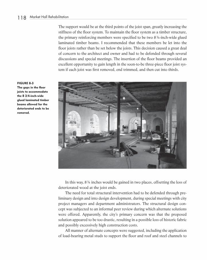
118 Market Hall Rehabilitation
The support would be at the third points of the joist span, greatly increasing the stiffness of the fl oor system. To maintain the fl oor system as a timber structure, the primary reinforcing members were specifi ed to be two 8 ¾ - inch - wide glued laminated timber beams. I recommended that these members be let into the fl oor joists rather than be set below the joists. This decision caused a great deal of concern to the architect and owner and had to be defended through several discussions and special meetings. The insertion of the fl oor beams provided an excellent opportunity to gain length in the soon - to - be three - piece fl oor joist sys-tem if each joist was fi rst removed, end trimmed, and then cut into thirds.
FIGURE 8-3 The gaps in the fl oor joists to accommodate the 8 3/4-inch-wide glued laminated timber beams allowed for the deteriorated ends to be removed.
In this way, 8 ¾ inches would be gained in two places, offsetting the loss of deteriorated wood at the joist ends.
The need for total structural intervention had to be defended through pre-liminary design and into design development, during special meetings with city project managers and department administrators. The structural design con-cept was subjected to an informal peer review during which alternate solutions were offered. Apparently, the city ’ s primary concern was that the proposed solution appeared to be too drastic, resulting in a possible loss of historic fabric and possibly excessively high construction costs.
All manner of alternate concepts were suggested, including the application of load - bearing metal studs to support the fl oor and roof and steel channels to
c08.indd 118c08.indd 118 12/18/08 10:13:30 PM12/18/08 10:13:30 PM

act as ledgers epoxy bolted to the masonry to support the fl oor joists and tie the fl oor system to the perimeter walls.
My intent to transform the fl oor system into a diaphragm had to be explained. Floor joist removal was integral to this effort also because the appli-cation of 5/4 (1 inch thick) diagonal fl ooring as a subfl oor was key to that effort. For the fi nish fl oor to remain at the original level, the fl oor joists would have to be lowered to compensate for the inch - thick diagonal fl oor sheathing. This could only be accomplished by temporarily removing all fl ooring and joists, and reworking the masonry joist pockets and bearing plates. Obviously, this would also require the installation of temporary shoring and bracing dur-ing construction to ensure stability of the masonry walls.
Various forms of cross - bracing or sheathing were suggested to be installed beneath the fl oor system by the architect, peer reviewers and city offi cials. All suggestions were aimed at not disturbing the fl oor joists in their original state. Unfortunately, decay and deterioration had greatly impacted a severely under-sized fl oor system, which would be required to support the display cases and exhibits of a newly minted Confederate Museum.
City managers insisted that the existing fl ooring would be diffi cult to remove without destroying it. To be fair, their concerns were fueled by the advice of peer review engineers and consulting contractors.
All of the suggested alternates seemed to contain either steel or plywood as a primary ingredient. Many of the suggestions were verbally transmitted without benefi t of a written report or calculations. Each was required to be debunked as we progressed over many months into the construction document phase. In my opinion, the steel - stud support system would not work because it would forever change the original structural system of the building. Often, structural engineers propose this solution without considering that the stability of the building depends on the weight of the fl oor system resting on the masonry walls. Take that away, and the original, thick masonry walls become unstable. Their answer, to tie the masonry to the studs, further debases the original system.
Although the American Plywood Association credits the ancient Egyptians with the invention of plywood by alternating the direction of grain of wood veneers in the construction of mummy cases, I did not want to use a twentieth - century construction material in the restoration of Market Hall. One concern of using plywood for such an application is that the layers of adhesive, although thin, might act as an improved vapor barrier, retarding the move-ment of moisture through a building. A practical reason for resisting the use of plywood is that traditional framing rarely is at an even spacing, accommo-dating 8 - or 12 - foot sheets of plywood without trimming. This leads to waste and additional labor.
Market Hall Rehabilitation 119
c08.indd 119c08.indd 119 12/18/08 10:13:32 PM12/18/08 10:13:32 PM

120 Market Hall Rehabilitation
Most structural engineers feel very comfortable designing steel structures. As a result, many reach for the Steel Manual when rehabilitating historic build-ings. There are places where structural steel is most appropriate, and often it is the only workable solution. For Market Hall, a masonry box with a timber lid, a traditional approach utilizing technology similar to the original, was called for.
FIGURE 8-4 The technology used is common to the timber period of original construction. (See color insert.)
Key to my concept was the utilization of restoration masons and timber framers in the restoration of Market Hall. The general contractor embarked on the project with the intention of utilizing his own forces to undertake the timber - frame portion of the work.
Many of the timber frame tasks were unique and diffi cult to execute. Besides rehabilitating the kingpost trusses in a traditional way utilizing through bolted splices and shear blocks, a seismic resisting X - bracing system had to be inte-grated into the attic to transmit shear forces between the masonry walls and the timber structure. Timber plates were keyed into the masonry with timber shear blocks that had to be laid up in the masonry and dapped into the timber plates. This work was required both at the main fl oor level and at the ceiling level.
Discussions between the design team, contractor, and the city managers fi nally resulted in subcontractor proposals being solicited from among a few qualifi ed individuals with timber frame credentials. The project specifi cations attempted to pre - qualify the timber framer component by requiring membership in the Timber Framers Guild of North America or other prerequisite experience. From the start, the work of timber framers Michael Goldberg of Woodstock,
c08.indd 120c08.indd 120 12/18/08 10:13:32 PM12/18/08 10:13:32 PM

Georgia and Peter Bull of Cleveland, Georgia greatly impressed project superin-tendent Tom Magee of NBM Construction.
Once the structural design concept was accepted by the County and the contractor was on board, work a Market Hall proceeded smoothly.
FIGURE 8-6 This completed building again houses the Confederate Museum. (See color insert.)
FIGURE 8-5 The iron work was restored to its original confi guration and color. (See color insert.)
Timber framers and masons worked together to rehabilitate a landmark building that had suffered greatly.
Market Hall Rehabilitation 121
c08.indd 121c08.indd 121 12/18/08 10:13:33 PM12/18/08 10:13:33 PM

122 Market Hall Rehabilitation
AWARDS
The Restoration of the 1841 Market Hall received the following honors:
Restoration and Renovation 2004 Palladio Award for the Restoration of Market Hall, Charleston, South Carolina 2003 South Carolina Historic Preservation Honor Award for the Resto-ration of Market Hall, Charleston, SC
2003 South Carolina Historic Preservation Honor Award — The Palmetto Trust for Historic Preservation SC Department of Archives & History Governors Offi ce for the Restoration of Market Hall, Charleston, South Carolina
2003 National Preservation Honor Award National Trust for Historic Preservation for the Restoration of Market Hall, Charleston, South Carolina
2002 Samuel Gaillard Stoney Conservation Craftsmanship Award by the Historic Charleston Foundation for work on the Restoration of 1841 for the Restoration of Market Hall, Charleston, South Carolina
2002 Carolopolis Award presented by The Preservation Society of Charleston for the Restoration of Market Hall, Charleston, South Carolina
•
•
•
•
•
•
c08.indd 122c08.indd 122 12/18/08 10:13:35 PM12/18/08 10:13:35 PM

123
C H A P T E R 9 Differential Settlement at St. Philip ’ s Moravian Church at Old Salem
D Differential settlement caused by the degradation of underlying organic materials is a common occurrence in many building sites. Often, a build-
ing is placed on marginally adequate soils without the benefi t of a deep founda-tion or the removal of pockets of organic material. A similar occurrence often happens when an addition to a church building is placed on top of a cemetery. The consolidation of these features can produce quite dramatic amounts of differential settlement. Correcting the problems associated with differential settlement is but one aspect of the Old Salem project, which included restora-tion of the existing church and replication of a previous log church known only through a single photograph, church history, and archeology.
HISTORY
The Salem community was founded in 1766 by the Moravians, a Protestant sect from Bethlehem, Pennsylvania, with origins in the Czech states of Moravia and Bohemia. How the Moravians came to North Carolina is quite interesting. In November of 1751, leaders of the Moravian church met in London to consider the offer of one of the Lords Proprietors, John Carteret, the Earl of Granville, to sell them a large tract of land in North Carolina. Under the leadership of
c09.indd 123c09.indd 123 12/18/08 10:14:39 PM12/18/08 10:14:39 PM
Structural Investigation of Historic Buildings: A Case Study Guide to Preservation Technology for Buildings,Bridges, Towers, and Mills. David. C. Fischetti © 2009 John Wiley & Sons, Inc.

124 Differential Settlement at St. Philip ’ s Moravian Church at Old Salem
FIGURE 9-1 Historical photograph provided by Old Salem, Inc.
FIGURE 9-2 The termite damaged fl oor joists were removed to provide access for the archeologist.
Count Zinzendorf, the Moravians accepted the offer and directed Bishop August Gottlieb Spangenberg to lead a small exploratory expedition into the interior of North Carolina to select a suitable tract of land. After much effort, the explorers staked out a tract containing 98,985 acres to be known as Wachovia. 1
c09.indd 124c09.indd 124 12/18/08 10:14:40 PM12/18/08 10:14:40 PM

From almost the beginning, enslaved and free African Americans lived in Salem. The African American congregation of St. Philip ’ s Moravian Church in the community of Salem was formed in 1822. In 1823, the Moravians con-structed for their black citizens a simple log church a few blocks south of Salem Square adjacent to the Stranger ’ s Graveyard. In 1861, the congregation moved into a newly constructed Greek Revival brick church, again built by the Moravians, which is now the oldest standing African American church build-ing in North Carolina. The black church prospered so well after the Civil War that the Moravian Church agreed to enlarge the building in 1890. The 1890 addition to the 1861 St. Philip ’ s Moravian Church in Winston - Salem was con-structed on a portion of the preexisting Stranger ’ s Graveyard. The addition contains two fi rst - fl oor rooms, a central corridor, and a balcony above. 2
REPLICATION AND RESTORATION
Work at St. Philip ’ s included the reconstruction of a replica of the 1823 log church based on photographic and archeological evidence. Restoration of the brick church included replication of the original steeple and underpinning repairs to the 1890 addition. The other major structural issue was to provide adequate support inside the attic of the log church for the addition of a repli-cated belfry and the additional weight of a mechanical unit.
FIGURE 9-3 The log church was replicated based on one photograph and archeological evidence.
Replication and Restoration 125
c09.indd 125c09.indd 125 12/18/08 10:14:42 PM12/18/08 10:14:42 PM

126 Differential Settlement at St. Philip ’ s Moravian Church at Old Salem
Between the two projects, structural engineering tasks at St. Philip ’ s included the design of traditional timber frames and connections, structural steel, under-pinning, masonry restoration and repair, and a number of construction details. Drawings for the log church were executed by John Milner Architects, Inc. of Chadds Ford, Pennsylvania, based on review, input, and sketches provided by us.
FIGURE 9-4 A pair of structural steel trusses was designed to support the replicated belfry.
FIGURE 9-5 The log church has a false chimney and cupola. (See color insert.)
c09.indd 126c09.indd 126 12/18/08 10:14:43 PM12/18/08 10:14:43 PM

For St. Philip ’ s, we provided comprehensive drawings depicting suggested underpinning, means and methods for the underpinning, and complete detail-ing of the steeple frame and supporting trusses.
DESCRIPTION OF THE CHURCH
St. Philip ’ s is approximately 40 feet wide by 85 feet long with exterior brick masonry walls and fi rst - fl oor framing above a crawl space. 3 We estimated that the 2 � 10 fl oor joists, spaced at 24 inches on center in the 1861 build-ing, were equivalent to No. 1 dense or better timber and the 1890 fl oor joists equivalent to No. 2 or No. 3 dense southern pine. The 1890 fl oor joists and fl oor sheathing were removed from the front portion of the building prior to construction so that archeologist could map the features without interference.
The roof of the 1861 church is framed with “ queen rod trusses ” consisting of 5 � 8 timber top chords, double 7/8 - inch square iron queen rods, 2 ¾ - inch by 3 ½ - inch braces (webs), and a bottom chord consisting of double 4 � 10 timbers spliced together with trunnels (wood pegs).
FIGURE 9-6 The bottom chord consists of two 4 � 10s.
Description of The Church 127
c09.indd 127c09.indd 127 12/18/08 10:14:46 PM12/18/08 10:14:46 PM

128 Differential Settlement at St. Philip ’ s Moravian Church at Old Salem
The exterior walls and the corridor walls of the 1890 addition are con-structed of brick masonry, with very shallow footings. Obviously, when setting the bearing elevation for the walls, the builders were well aware of the numer-ous burial sites in the area of the addition.
Subsidence of the remains within disturbed pockets in the stiff clay caused major cracks to form in the exterior walls at the northwest corner of the 1890 building addition. Numerous settlement cracks in the masonry of the north-west corner of the 1890 addition were obvious by the 1980s.
The cracks extended from the base to the top of the wall on both the front face and north side of the building. The cracks were through - wall cracks as much as 1 ½ to 2 inches in width.
During the exploratory phase, distance from the underside of the fl oor joists to the bottom of the walls was measured to be from 17 ¾ inches to 26 inches. The bases of the walls were found to be rectangular in shape without projec-tions or footings of any kind. The foundation walls, as found, were approxi-mately 17 ½ inches thick at the exterior locations and 8 inches thick at the corridors. The oversized brick units of the 1890 addition measured 3 inches high, by 4 inches wide, by 8 inches in length.
FIGURE 9-7 The connection at the queen rod joint appears to have been reworked during the original construction.
Technically, these members constitute an assembly better described as tied and braced principal rafters with sag rods.
c09.indd 128c09.indd 128 12/18/08 10:14:48 PM12/18/08 10:14:48 PM

FIGURE 9-8 The northwest corner was temporarily braced prior to our involvement with this project.
FIGURE 9-9 The cracks extended to the top of the wall and were up to 2 inches in width.
RECOMMENDATIONS FOR REPAIR
Our involvement in this “ little church repair ” spanned a period of more than 10 years. The original preliminary structural evaluation report was based on a January 1993 jobsite observation made for architect Charles A. Phillips of the
Recommendations for Repair 129
c09.indd 129c09.indd 129 12/18/08 10:14:50 PM12/18/08 10:14:50 PM

130 Differential Settlement at St. Philip ’ s Moravian Church at Old Salem
fi rm Phillips & Oppermann, P.A. of Winston - Salem. In a condition assessment report of that visit, we stated the following:
Although the walls of the 1890 addition can be successfully underpinned, it will require considerable engineering to accomplish the task. Consideration should be given to removing the 1890 addition altogether.
The two reasons for recommending this alternative are that the 1890 addition should not have been built over a cemetery to begin with, and sec-ond, replacing the steeple with the 1890 addition intact would result in a church with a steeple located at the third point of its length in lieu of directly above the narthex 3 .
By 1995 it was made clear to me that St. Philips would have to be inter-preted as an 1890s building and the addition could not be removed. In a letter to John Larson of Old Salem, Inc., we listed “ the order of tasks required to repair the front section of the church . . . ” 4 First, the cracks in the masonry needed to be located, in the drawings, on the building elevations. The location of the graves under the addition needed to be mapped, noting the depth of these features and the extent of undisturbed soil. With the benefi t of an archeological base map and a geotechnical report, the type, number, location, and depth of the mini piles (or other ground modifi cation techniques) would be determined so that budget prices could be derived. By this time, John Milner had been retained to execute the design of both the log church and St. Philip ’ s Moravian Church restoration.
In 1993, we had recommended that a subsurface investigation be under-taken “ to determine the relative depth and confi guration of the 1861 and 1890 wall footings, as well as the nature of the soils located directly beneath the footings in both areas. ” 3 Successful underpinning of a wall requires that it be uniformly supported continually along its length. It was obvious that support needed to be provided along the wall by bridging the less consolidated pockets of soil without disturbing those areas. The main purpose of the proposed soils investigation was to determine the capacity of the fi rm soils to support a con-tinuous grade beam with, or without, the installation of soil modifi cation or support elements, such as piles. If suffi cient support could be obtained in the undisturbed locations, then a continuous concrete grade beam could be designed to span the archeological features. The underpinning approach that we devised was to install the mini piles fi rst so that they could be used for tem-porary support of the building and act as “ hard points ” to jack against in lifting the badly cracked masonry walls. In order to be successful, the walls would have to be lifted and pulled together simultaneously. In this way, the maximum amount of existing masonry could be retained by merely closing the cracks.
c09.indd 130c09.indd 130 12/18/08 10:14:53 PM12/18/08 10:14:53 PM

The project documents included structural details and notes that spelled out a suggested sequence of work, a suggested method for execution, and a layout of the mini piles.
SUBSURFACE EXPLORATION
Froehling & Robertson, Inc. of Raleigh, North Carolina, was fi nally authorized to undertake a subsurface exploration in April of 2002 to evaluate subsurface conditions for underpinning of the west wall of the addition. At our request, it had provided a proposal for this work in 1993. F & R drilled two 40 - foot - deep borings approximately 5.5 to 6 feet west of the exterior face of the west wall at locations cleared by the project archeologist. Borings were drilled with an all - terrain CME - 550 drill rig using hollow stem augers to advance the borings. 5
The usual approach of including “ test ” pits, also known as observation pits , in the soils exploration was not necessary because the work of the arche-ologist exposed the bottom of the walls in the interior of the 1890 addition. The confi guration of the base of the wall and the nature of the supporting soils could be observed without the need for observation pits.
General engineering characteristics of the subsurface soils were deter-mined from samples obtained at selected intervals in accordance with Stand-ard Penetration Tests (SPT) procedures (ASTM D - 1586). Beneath a thin veneer of topsoil and approximately 2 feet of fi rm, silty clay residual soil, there was 8 to 12 feet of very stiff micaceous, fi ne sandy silts. Extending for the remain-ing 40 feet of depth, fi rm to stiff slightly micaceous to very micaceous, fi ne sandy silts were encountered. After 24 hours, a piezometer installed in Boring B - 1 detected no groundwater. F & R concluded that the conditions encountered at the two borings would be favorable for the installation of friction - type mini piles to a depth approximately 25 to 35 feet below existing grades. F & R anticipated that steel mini piles could develop a design skin friction of 300 to 400 pounds per square foot. 5
THE LOG CHURCH
The schedule for the reconstruction of the 1823 log church, which included historical research, archeology, design reviews and approvals, and construc-tion, was developed by John Larson of Old Salem, Inc. The log church was scheduled to be opened for visitors as the plans and specifi cations for the 1861/1890 masonry church were completed. Most of this work occurred in
The Log Church 131
c09.indd 131c09.indd 131 12/18/08 10:14:53 PM12/18/08 10:14:53 PM

132 Differential Settlement at St. Philip ’ s Moravian Church at Old Salem
1996 and 1997. Starting in July 1991, archeologist Dr. Leland Ferguson from the University of South Carolina and his team of students had verifi ed the orig-inal location of the 1823 log church and located 120 to 130 graves of people buried in the Stranger ’ s Graveyard between 1775 and 1890. 4
Although Old Salem had photographic and archeological evidence of the log church, the confi guration of the structural system to support the roof was based on conjecture and other similar buildings. Structural design issues at the log church included the design of an A - frame roof structure, support of the false chimney clad with brick veneer, bracing of the gable endwalls, design and support of the open belfry, determination of porch and balcony details, tie - down details connecting the log structure to the foundation and the design of the roof structure. The principal element in the roof structure for the log church is partially exposed to view tied A - frame, with the collar tie located approximately midway between the apex of the frame and the level of the supports.
FIGURE 9-10 The A-frames with collar ties were pre-fabricated in a shop.
Three horizontal ties were placed across the building at the top of the log walls to resist the horizontal thrust of the A - frames. A traditional timber joint consisting of a tongue and fork type connection was inadequate for the loads involved in these tie members, and the end connections had to be reinforced with steel.
c09.indd 132c09.indd 132 12/18/08 10:14:54 PM12/18/08 10:14:54 PM
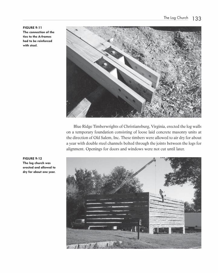
Blue Ridge Timberwrights of Christiansburg, Virginia, erected the log walls on a temporary foundation consisting of loose laid concrete masonry units at the direction of Old Salem, Inc. These timbers were allowed to air dry for about a year with double steel channels bolted through the joints between the logs for alignment. Openings for doors and windows were not cut until later.
FIGURE 9-11 The connection of the ties to the A-frames had to be reinforced with steel.
FIGURE 9-12 The log church was erected and allowed to dry for about one year.
The Log Church 133
c09.indd 133c09.indd 133 12/18/08 10:14:55 PM12/18/08 10:14:55 PM

134 Differential Settlement at St. Philip ’ s Moravian Church at Old Salem
At one point, the partially complete (under construction) church structure, with roof structure installed, was moved off its foundation by high winds. The building was lifted and pushed by the wind, causing the bottom log at the rear to fall out and others to be displaced. The roof suffered no damage. The damage was relatively easy to fi x, and construction resumed.
UNDERPINNING WITH MINI PILES
Foundation Services, Inc., which at the time was a division of Hayward Baker, Inc. located in Greensboro, North Carolina, was contacted regarding possible approaches to underpinning the west end of the church. Scott Harshman of Foun-dation Services determined that the existing door openings into the church were large enough to permit the passage of the equipment required to install mini piles. A pile is a long, slender, timber, steel, or concrete structural element driven, augered, jetted, or otherwise embedded on end into the ground for the purpose of support, or to modify or stabilize the earth. In this case, Hayward Baker, Inc. recommended the use of relatively small - diameter piles called mini piles, pipe piles, pin piles, pen-cil piles, or tubular steel piles. The advantages of mini piles are that they can be drilled or driven through virtually any subsurface condition with drill rigs small enough to access diffi cult areas with low headroom. In some cases, similar pier and pile systems are hydraulically advanced depending on the nature of the soil.
FIGURE 9-13 The shoring beams are supported on the mini piles
c09.indd 134c09.indd 134 12/18/08 10:14:58 PM12/18/08 10:14:58 PM

Once the gaps in the masonry walls were closed, the cracks could be “ healed ” by a combination of rebuilding and stitching. The stitching process relies on the installation of retrofi tted joint reinforcing placed into raked - out horizontal mortar joints straddling the cracks. By necessity, the masonry repairs had to occur after the walls were fully supported by the underpinning system consisting of temporary steel beams and mini piles. A new cast - in - place rein-forced concrete footing served as both pile cap and grade beam, spanning between the piles while supporting the wall above. The piles were inserted between the features mapped by the archeologist into stiff soil. The archeologist pro-vided an AutoCAD ® layout of the Stranger ’ s Graveyard, which we incorporated into the structural drawings, enabling us to direct the placement of the piles in undisturbed locations. To avoid confl ict, the concrete footing was set as high as possible, but comfortably below grade.
CONSTRUCTION
Structural drawings included photographs of existing conditions showing repairs to the masonry and suggested ways to brace the building. These draw-ings, as well as specifi cations — including a section describing mini piles — were included in the bid package. The low bidder for the restoration, general contrac-tor H. M. Kern Corporation, selected Foundation Services, Inc. of Greensboro (now Hayward Baker, Inc.) and Blake Moving Company of Greensboro, North Carolina, as the subcontractors.
Hayward Baker, Inc. utilized a KB1 Drill Rig with a hydraulic generator and a diesel powered grout mixer. A 2.2 - to - 1 Portland cement - to - water ratio was used to achieve a grout design mix with a compressive strength of 4,000 psi at three days. The design capacity of the 4 - inch outside diameter micropiles was 5 tons, with a factor of safety of 2.2. The 4 - inch O.D. piles had a wall thickness of 0.525 inches, with a yield strength of Fy � 36 ksi. Piles were inserted in accordance with our layout with the exception of three, which had to be offset slightly to avoid obstructions to the drill rig.
Charlie Blake of Blake Moving Company used a simple and direct method to pull the walls together.
Sets of fl at steel bands were placed horizontally around straight sections of wall.
Head joints in the masonry were knocked out so that the bands could pass through each section of wall, encompassing the portion to be pulled together. This operation required that the open cracks be cleared of debris so that the cracked sections of wall could be leveled and moved while “ fl oating ” on steel.
Construction 135
c09.indd 135c09.indd 135 12/18/08 10:14:59 PM12/18/08 10:14:59 PM

136 Differential Settlement at St. Philip ’ s Moravian Church at Old Salem
FIGURE 9-14 The mortar in the cracks had to be removed prior to pulling the wall together.
FIGURE 9-15 Bands of steel were installed through mortar joints. Building corners were protected with wood.
Using the “ banding system, ” the discontinuous sections of wall were slowly and carefully pulled together so that the mason could heal the cracks using common masonry restoration techniques.
The reconstruction of the belfry of the masonry church proved to be inter-esting. Its confi guration was determined by Philips & Oppermann, using the
c09.indd 136c09.indd 136 12/18/08 10:14:59 PM12/18/08 10:14:59 PM

early photograph that showed it and the log church. Other evidence included the remnants of the belfry support timbers and framed out openings in the attic. We determined that without supplemental support, the existing structure was inadequate to resist forces derived from wind acting on a new belfry. The solu-tion was to design a wood - framed belfry supported by a pair of steel trusses to span the width of the church.
FIGURE 9-16 The masonry wall was supported by the mini-piles. Steel bands were used to provide under-slung support to the wall. (See color insert.)
FIGURE 9-17 The steel trusses were designed to be lightweight with bolted connections to ease assembly within the attic space.
Construction 137
c09.indd 137c09.indd 137 12/18/08 10:15:02 PM12/18/08 10:15:02 PM

138 Differential Settlement at St. Philip ’ s Moravian Church at Old Salem
These trusses were located in the attic, spaced to avoid the original framing. An added consideration was the erection of this structural system in an tight space. To accommodate the geometry and allow for assembly in place, the steel truss components and lateral bracing consisted of structural angles fi eld - bolted together.
SUMMARY
The underpinning fi x for St. Philip ’ s consisting of strategically placed mini piles, concrete grade beams, and the efforts of a general contractor and his subcontractors consisting of a foundation specialty contractor, a structural mover, and a masonry restoration contractor to provide permanent support for the building while avoiding the archeological features beneath the building that were the source of its distress.
REFERENCES
1. C. Daniel Crews, Villages of the Lord, The Moravians Come to Carolina (Winston - Salem: Moravian Archives, 1995).
2. Old Salem, St. Philip’s Church, An Overview, (Winston - Salem: Old Salem, Inc., June 11, 2003).
3. Fischetti, David C. “ Preliminary Structural Evaluation ” Report, January, 1993.
4. Fischetti, David C., Letter to John Larson, 1995. 5. Charles A. Phillips, St. Philip ’ s Moravian Church, Report of Findings,
(Winston - Salem: Phillips & Oppermann, P.A., 1993).
BIBLIOGRAPHY
John Sensbach , Preserving North Carolina ’ s Old Surviving Black Church , North Carolina Preservation , #86 Summer 1992 .
Ralph E. Sanders , Report of Subsurface Exploration , Froehling & Robertson , Inc., No. D66 – 002, April 15, 2002 .
c09.indd 138c09.indd 138 12/18/08 10:15:05 PM12/18/08 10:15:05 PM

139
C H A P T E R1 0 James Madison ’ s Montpelier
J James Madison ’ s Montpelier is a historic building, with great cultural value, now undergoing a $ 60 million dollar transformation, restoring it to the size
and form it was in the 1820s. This is no small task. The rural Virginia home of James Madison, fourth president of the United States had been altered in the mid - and late nineteenth century and greatly expanded after William DuPont Sr. purchased it in 1901.
The ninth owner of Montpelier, the National Trust for Historic Preserva-tion, engaged the architectural department of Colonial Williamsburg in 1997 to undertake a study to determine how the building evolved. This, and other studies, contributed to a body of knowledge that expanded during construction to include information gleaned through the hands - on work of archeologists, architectural historians, architects, engineers, and the various craftsmen engaged to undertake the work.
Restoring Montpelier to an earlier time has involved many complex struc-tural issues. These had an array of solutions ranging from traditional repairs, to the application of modern materials, depending on the overall goals of the project. For example, the roof structure consisting of braced principal frames, which had been partially cut out to convert the attic into habitable space.
Replacing the missing parts and reinforcing the heel, brace, and post connec-tions of the principal frames to compensate for deterioration and defects involved the application of traditional timber joinery, as well as modern connectors.
c10.indd 139c10.indd 139 12/18/08 10:17:00 PM12/18/08 10:17:00 PM
Structural Investigation of Historic Buildings: A Case Study Guide to Preservation Technology for Buildings,Bridges, Towers, and Mills. David. C. Fischetti © 2009 John Wiley & Sons, Inc.
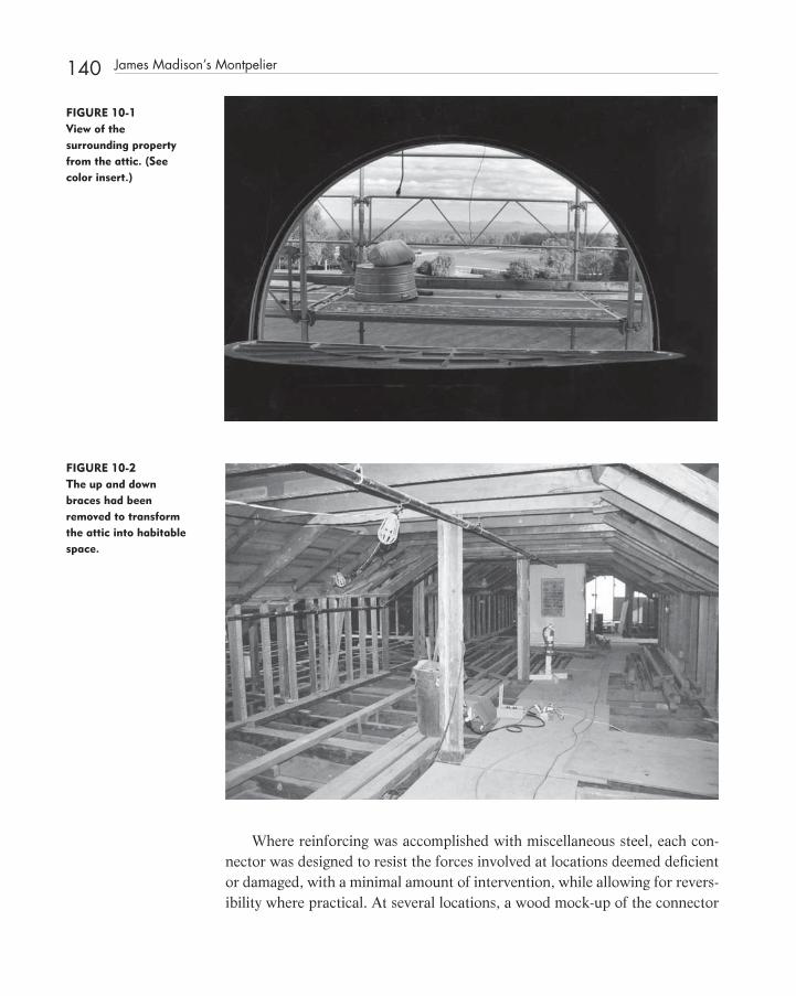
140 James Madison ’ s Montpelier
FIGURE 10-1 View of the surrounding property from the attic. (See color insert.)
FIGURE 10-2 The up and down braces had been removed to transform the attic into habitable space.
Where reinforcing was accomplished with miscellaneous steel, each con-nector was designed to resist the forces involved at locations deemed defi cient or damaged, with a minimal amount of intervention, while allowing for revers-ibility where practical. At several locations, a wood mock - up of the connector
c10.indd 140c10.indd 140 12/18/08 10:17:01 PM12/18/08 10:17:01 PM

assembly was made to ensure an adequate fi t. The actual wood mock - ups were provided to the steel fabricator, along with the engineer ’ s drawings. The small fabrication shop had tool - and - die capabilities, and was not strictly a miscella-neous steel fabrication shop. As a result, reinforcing connections were made with great precision, in stainless steel, to suit each individual situation.
FIGURE 10-3 The braces were replaced in kind.
FIGURE 10-4 The post-to-beam connection was damaged in several locations.
James Madison ’ s Montpelier 141
c10.indd 141c10.indd 141 12/18/08 10:17:05 PM12/18/08 10:17:05 PM

142 James Madison ’ s Montpelier
Some rafters, beams, and purlins required reinforcing with steel knife plates where a simple traditional scarf joint would not suffi ce.
FIGURE 10-5 Each reinforcing connection was custom fabricated by providing a wood mockup to the steel fabricator for each location.
FIGURE 10-6 The proposed knife plate connection was load tested.
c10.indd 142c10.indd 142 12/18/08 10:17:07 PM12/18/08 10:17:07 PM

In these cases, the knife - plate connection actually preserved the maximum amount of historic fabric.
FIGURE 10-7 Several rafters were spliced with knife plates to maximize the retention of original fabric.
Deterioration in several beams and timber plates and sills was verifi ed, and in some cases discovered, through the use of resistance drilling.
FIGURE 10-8 Wood scientist Ron Anthony used resistance drilling to discover deterioration in timber member.
James Madison ’ s Montpelier 143
c10.indd 143c10.indd 143 12/18/08 10:17:10 PM12/18/08 10:17:10 PM

144 James Madison ’ s Montpelier
Segmental infi ll using laminated veneer lumber was used at two locations. The serrated roofs of the wings were reconstructed on the basis of histori-
cal writings, prints, architectural evidence, and knowledge of similar construc-tion at other sites contemporary to Montpelier, such as Thomas Jefferson ’ s Monticello, Poplar Forest, and the University of Virginia. Anchorage of the plates supporting the serrated roof joists to the masonry included tie - down anchors and shear keys to resist lateral loads such as wind and seismic.
FIGURE 10-9 The serrated roof followed Thomas Jefferson’s original design, which was verifi ed by “ghost” marks.
The structural interventions typically were exposed to a process that included review by the architects (The architectural fi rm of Mesick Cohen Wilson Baker Architects of Albany New York), the on - site project superintendent, John Jeanes (Director of Restoration) for Montpelier, Inc., the various craftsmen undertak-ing the work, and the Restoration Advisory Committee engaged by the owner.
Structural concerns at Montpelier included reconstructing the sawtooth roofs, reconstructing the portions of the hipped roof structures modifi ed by DuPont, and reinstalling roof framing, consisting of posts and up and down braces, which were removed to create an apartment from the attic space. In reverting that space back to an attic, fl oor joists that had been added were removed. Two dormers were removed and the associated framing was replaced by splicing. Timber plates were installed after the two - story wings were lowered to their original one - story condition. Anchors were installed throughout the structure to ensure resistance against wind.
Every area of the building required some timber repair or reconstruction and masonry reconstruction, underpinning, or repair. We persuaded John Jeanes to
c10.indd 144c10.indd 144 12/18/08 10:17:12 PM12/18/08 10:17:12 PM

engage Arnold M. Graton of Ashland, New Hampshire, to level the fl oors. Arnold also underpinned the 1750 chimney to provide a 2 - foot - tall vertical clearance at its base to allow mechanical ducts to transition into the vertical space within the chimney.
FIGURE 10-10 Arnold Graton (shown here) temporarily braced the chimney prior to removing soil and installing jacks. (See color insert.)
Arnold used 16 jacks to support the chimney mass.
FIGURE 10-11 The jacks consisted of 20-ton air jacks with dial gauges.
James Madison ’ s Montpelier 145
c10.indd 145c10.indd 145 12/18/08 10:17:14 PM12/18/08 10:17:14 PM

146 James Madison ’ s Montpelier
The mason constructed the chimney, fi lling the gap between the original chimney and a new concrete footing.
The newer fl oor openings had to be closed up and the original stair open-ings reconstituted. In some cases, framing for fl oor openings became quite complex. Joist hangers, splice plates, and laminated veneer lumber were all utilized in an effort to make more than adequate repairs while removing as lit-tle historic fabric as possible. We utilized Dutchman inserts with epoxy to repair some deteriorated timbers.
In the lower level, one large deteriorated beam was repaired by removing the deteriorated center of the beam and replacing it with laminated veneer lumber.
Many of the original connections required enhancement for the members joined to carry the required load. The connection between the attic posts and the ceiling and dragon beams became a very complicated connection of stain-less steel, which was fi rst patterned in wood and then built by a small tool and die shop using the wood pattern as a guide.
FIGURE 10-12 The chimney extension provided duct access into the vertical spaces within the chimney. (See color insert.)
c10.indd 146c10.indd 146 12/18/08 10:17:17 PM12/18/08 10:17:17 PM
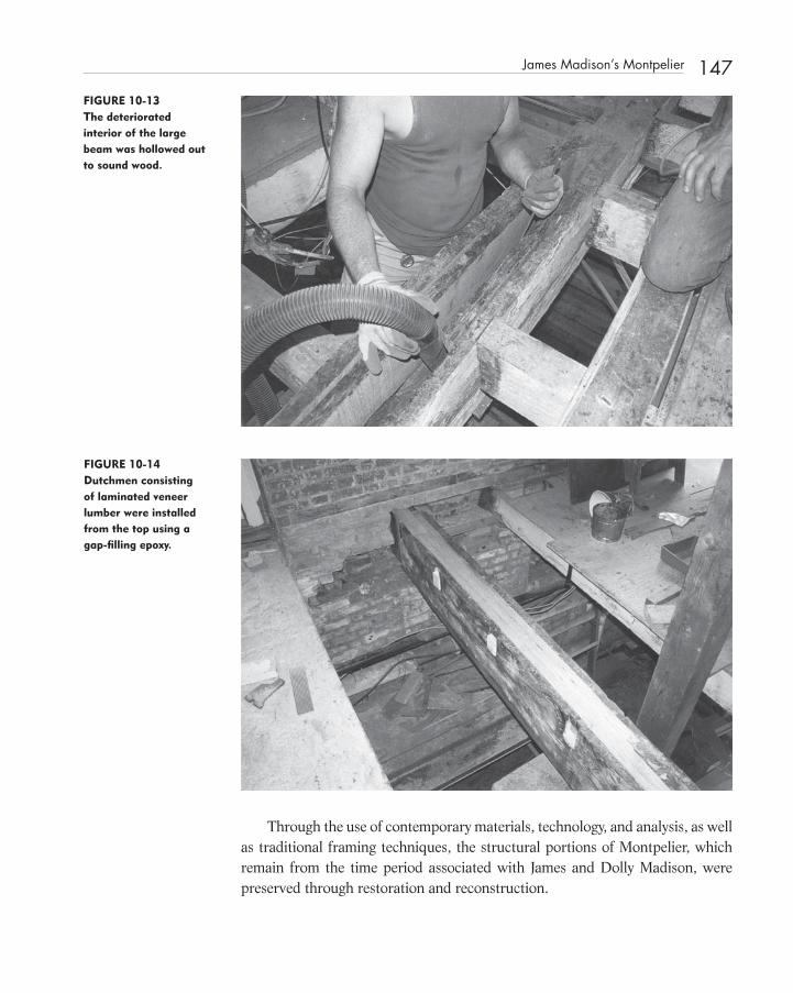
FIGURE 10-13 The deteriorated interior of the large beam was hollowed out to sound wood.
FIGURE 10-14 Dutchmen consisting of laminated veneer lumber were installed from the top using a gap-fi lling epoxy.
Through the use of contemporary materials, technology, and analysis, as well as traditional framing techniques, the structural portions of Montpelier, which remain from the time period associated with James and Dolly Madison, were preserved through restoration and reconstruction.
James Madison ’ s Montpelier 147
c10.indd 147c10.indd 147 12/18/08 10:17:18 PM12/18/08 10:17:18 PM

149
C H A P T E R1 1 Timber, Glulam, and Conservation
M Meeting the requirements of the building code is not the same as assuring the public of a safe structure. As structural engineers, it is critical that we
make the judgments needed to keep a historic structure in service when param-eters appear to fall short of minimum code requirements.
In this chapter we will discuss timber structures in general and the struc-tural repair of glued laminated timber structures and the use of laminated timber in the conservation of other timber structures.
TIMBER MISUNDERSTOOD
Timber is the primary structural component for most historic structures in the United States and Canada.
In today ’ s residential market, timber is primarily of importance as dimen-sion lumber. Most timber production consists of dimension framing.
Manufacturers provide the design for prefabricated components such as wood trusses for the complete framing of fl oors and roofs. Other manufac-tured products, such as laminated veneer lumber and joist products, are selected on the basis of load tables provided by the manufacturer. As a result, the glued laminated timber industry is one of the few areas where structural engineers are practicing the design of heavy timber structures on a daily basis. Some timber - frame manufacturing fi rms have in - house engineers, but most use the services of private consulting engineers.
c11.indd 149c11.indd 149 12/18/08 10:17:59 PM12/18/08 10:17:59 PM
Structural Investigation of Historic Buildings: A Case Study Guide to Preservation Technology for Buildings,Bridges, Towers, and Mills. David. C. Fischetti © 2009 John Wiley & Sons, Inc.
150 Timber, Glulam, and Conservation
PRESERVATION PHILOSOPHY
It is hoped that by learning more about timber design, structural engineers will develop a preservation philosophy that demands rigorous analysis in order to justify “ doing nothing ” to an historic timber structure that has been perform-ing satisfactorily for many years. Buildings that analysis (and observation) clearly indicates are unsafe should be reinforced in the most sensitive manner in an attempt to retain as much historic fabric as possible. Buildings that require extensive modifi cation or reconstruction should be restored in a way that is in keeping with the original construction if possible, while fulfi lling safety requirements. Often, engineers are asked to evaluate framing members to determine the capacity of an existing fl oor structure in an historic structure. This review process differs considerably from design.
STRUCTURAL REVIEW
Members in the horizontal plane, such as fl oor sheathing, joists, purlins, and beams, are stressed principally in bending. The resisting bending moment is a measure of the strength of such an element. This measure, stiffness and hori-zontal shear make up the three qualities that are normally checked during the process of selection that we call design. Because timber is available in certain standard lumber sizes, the designer selects from the available sizes, grades, and species those that most economically meet the predetermined standards for bending stress, defl ection, and horizontal shear. When the engineer reviews the capacity of an existing member, many parameters complicate the process of selecting appropriate lumber. Size, span and spacing of members are dictated by the structure. It is the engineer ’ s task to determine the size, orientation, spe-cies, grade, and end condition of all of the structural elements in a building that already exists. Between the factors of limited availability of types of lum-ber, economic considerations, existing standards, and the structure of the building itself, freedom of choice is eliminated.
ENGINEERING JUDGMENT
Often, the structural engineer must pass judgment on a structure that has served far beyond what we consider to be a normal period of service. The timbers of such a structure were not selected on the basis of modern engineering analysis. They certainly do not bear inspection marks attesting to their grade and species.
c11.indd 150c11.indd 150 12/18/08 10:18:00 PM12/18/08 10:18:00 PM

It should be obvious to the engineer that a safe fl oor structure should not fail in bending due to the actual loads imposed. But it is important to recognize that excessive defl ection, excessive vibration, or a lack of stiffness, should not automatically categorize a fl oor structure as “ unsafe. ” Strict defl ection limita-tions should be set for fl oors that support plaster ceilings in lieu of wood or tin ceilings or no ceilings at all. But for comfort, the defl ection limitation set in most building codes for fl oors, no matter what the ceiling, is 1/360th of the span.
It must be said that overstressed structural members may also be perfectly safe. It is important for the engineer to evaluate the basis for his or her conclu-sion regarding the safety of the structure. When making such an evaluation, the loads assumed for design should be reconciled with the actual loads that will occur in service. For example, if we think about the uniform design live load of 40 psf for residential fl oors used as living areas, packing a group of people weighing 160 pounds each into a room and allocating four square feet of space each would be equal to 40 psf. In reality, it is diffi cult to imagine such a situa-tion, and when one considers that most furniture weighs less per square foot, it is very diffi cult to see how residential fl oor loading could attain 40 psf.
The design values that we assume are critical to the computed capacity of some fl oor systems. For structures such as mill buildings, average design values yield results that fall well above the minimum code requirements for adaptive reuse occupancy, such as Offi ce or Retail.
LOAD DURATION AND HISTORIC STRUCTURES
The procedures of load factor design in timber were developed over a period of 10 years based on 20 years of research. In 1996, the American Forest & Paper Asso-ciation published the fi rst Load and Resistance Factor Design (LRFD) manual.
This concept is most appropriate for application to timber design because of the long history of the concept of Live Load Duration. Early timber research found that timber reacts quite well to short applications of load. The duration of load was found to be as critical as the magnitude of the load. Presumably, this sensitivity to the duration of load is a result of the natural composition of timber, which consists of a tightly bound bundle of cells that tend to stretch or elongate with time. The larger and more constant the load, the more stretching of fi bers occurs. The effects of this creep can be seen in many timber structures through excessive defl ection. For short durations of load, such as impact, allowable design values are substantially increased.
Research into this time - versus - stress relationship is of paramount impor-tance. Only through evaluating historic timber structures can we solve this
Load Duration and Historic Structures 151
c11.indd 151c11.indd 151 12/18/08 10:18:00 PM12/18/08 10:18:00 PM

152 Timber, Glulam, and Conservation
puzzle, which is complicated by cyclic loading, original moisture content, member size, span, species, grade, temperature, humidity and magnitude of stress. Although the concepts of LRFD design are most appropriately applied to timber structures, the vast majority of practicing timber engineers continue to use working stress design (WSD).
CASE HISTORIES
The portico of the Miles Brewton House in Charleston, South Carolina (c.1757), required a timber 6 � 18 in size and 52 feet long. Glued laminated timber was specifi ed because of the need for such a large member. The replace-ment roof structure for the Thomas Day/Union Tavern (c.1850) in Milton, North Carolina, includes laminated veneer lumber. The tapered rafter, collar tie, and ceiling joist system duplicates the profi le of the original structural ele-ments, which were destroyed in a fi re three years before we fi rst inspected the building in 1977. Of course “ modern” timber products should not automati-cally replace traditional timber framing and joinery. Replacement - in - kind of members with mortise and tenon, dovetail, tongue and fork, slotted, or oak - pinned joint connections is a possibility that must be considered. In recent years, various designs for new post - and - beam frames have been produced con-taining few or no metal connectors. Traditional technology is available through timber framers located in many areas of the United States and Canada.
In a 1988 structural evaluation report, we concluded that the large second fl oor assembly hall of the Chowan County Courthouse in Edenton, North Caro-lina (c.1767), could be used for public occupancy if the area was posted to limit the number of people to 200. A defl ection limitation of 1/360th of a span governed the design, producing a bending stress as high as 2292 psi in large, dense southern pine timber fl oor joists and beams.
In 1991, we reviewed the fl oor structure of the 1917 Walker Building at the State Hospital in Concord, New Hampshire. Assuming a reasonable set of design values equivalent to No. 1D SR southern pine, based on examination of wood samples obtained from the building, we concluded that the existing 7 ½ � 11 timber beams were adequate to support a live load of 86 psf, which is well within the 50 psf required for offi ce occupancy. The live load defl ection limita-tion of 1/360th of the span controlled the design. Of course, we can conclude that this is a safe structure that meets minimum code requirements. The calcula-tions were based on reasonable assumptions of design values.
In 1985, half a dozen fl oor joists from the 1903 Montague Building in Raleigh, North Carolina, were removed from the building and tested to destruction. Of the
c11.indd 152c11.indd 152 12/18/08 10:18:00 PM12/18/08 10:18:00 PM

fi ve joists tested, (of six joists selected, one was found not suitable for testing) the average bending stress at rupture was in excess of 5000 psi. The average modulus of elasticity was 1,295,000 psi. These measures of strength and stiffness were used to evaluate the capacity of the fl oor structure. To meet tenant requirements for possible retail occupancy in this speculative offi ce building, we recommended that all of the existing fl oor joists be reinforced.
At Moorfi elds, a 1792 house in Hillsborough, North Carolina, we evaluated the excessive defl ection of a summer beam by measuring offsets in the fl oor sur-face above the beam. Based on fi eld measurements and computer analysis, we were convinced that the two - span summer beam had failed. Indeed, when exposed to view by removing the ceiling plaster, during construction in 1980, the summer beam contained a severe fracture consistent with a typical bending failure. The only replacement beam available of suffi cient stiffness and strength that would fi t in the space between the fl oor sheathing and the plaster ceiling below was a steel tube section of a dimension approximately equal to the original timber beam.
St. Michael ’ s Episcopal Church in Charleston, South Carolina was built between 1752 and 1761. Architect unknown, it resembles English pattern book designs, which were popular in the colonies. St. Michael ’ s, is similar to James Gibbs ’ design for St. Martin - in - the - Fields in London. St. Michael ’ s sur-vived wars, hurricanes, tornadoes, fi res, and the 1886 earthquake. During the Revolutionary War, St. Michael ’ s was the center of British resistance, and as such, the tower was a target for British naval gunners. The 186 foot tall steeple served as an observation post and navigational landmark in this and subse-quent military confl icts. As a result of the 1886 earthquake, the steeple settled 8 inches, while leaning 18 inches towards the west requiring reconstruction of the portico below. Repaired cracks in the brick masonry can be observed today from the inside of the tower.
Hurricane Hugo, which struck near Charleston at the Isle of Palms on September, 22, 1989 caused damage to St. Michael ’ s resulting in an insurance settlement of $ 6,000,000. An indication of the strength of the winds was the damage to the weather vane at the top of the steeple. Consisting of a tapered 2 ½ inch square wrought iron bar, it was bent by the winds of this category 4 storm.
The steeple of St. Michael ’ s consists of fi ve stages above the roof. Its base, square in plan, forms the center portion of the vestibule. These brick masonry walls vary from 4 feet - 9 ½ inches to 5 feet - 3 inches in thickness. The masonry box, translating from square to octagon in stages; it extends to the underside of the gallery level.
Since the spire consists of four intersecting frames, we applied a 48 to 55 psf wind load to a pie shaped portion of the plan. At the same time, preliminary observation indicated that the eight posts at the open lantern level had various
Case Histories 153
c11.indd 153c11.indd 153 12/18/08 10:18:01 PM12/18/08 10:18:01 PM

154 Timber, Glulam, and Conservation
amounts of deterioration in their bases. The analysis indicated that the steeple frame acted much less stiff with one or both these joints disconnected.
Subsequent to Hurricane Hugo, I was contacted by Craig Bennett, P.E. of Cummings and McCrady, Inc. architects, in Charleston through a recommenda-tion from materials conservator George T. Fore of Raleigh, North Carolina. George Fore produced a condition analysis and conservation study of the carpentry, masonry, plaster and fi nishes, and various details. He also provided framing details for the steeple as well as evidence of racking of the upper structure due to Hurricane Hugo. His report located areas of deteriorated wood within the framework.
To determine the amount of lean in the steeple a surveying instrument was set in the window of a nearby offi ce building, but measurements were incon-clusive. Upon inspection on a day with fi ve to ten mile per hour gusts, Craig Bennett led the author on a tour up into the tower in similar fashion to the tours afforded through the years to dignitaries visiting Charleston such as George Washington and the Marquis de Lafayette. On those occasions appar-ently it was common practice to afford such dignitaries “ a view of the city “ .
The analysis of a steeple should consider wind pressure in four directions. Overall, stability depends on anchorage to the building ’ s foundations. Some stee-ples consist of a spire connected to a bell tower. In these cases, the analysis must include the steeple frame and its connection to the bell tower, whether masonry or stone. Steeples may consist of freestanding timber structures or timber struc-tures where one or two walls are integrated into endwall framing. Many steeples bear on the endwall of the church with two supports and with two supports on the fi rst interior roof truss. In many cases the two interior posts may pass through a balcony structure. Endwalls may be timber frames or masonry walls.
No matter what the confi guration, wind and seismic forces should be applied in the transverse direction across the ridge and in the longitudinal direction parallel to the ridge. Many steeples lean towards the nave in situa-tions where support is shared between an endwall and a less stiff roof truss. Even with a rigid support of timber posts and balcony or narthex wall framing, a steeple will lean if the endwall support is a non - yielding masonry wall. In these cases, a small amount of shrinkage across the grain in several large tim-ber plates can cause a dramatic lean in a tall steeple towards the nave.
For ease of analysis the timber frame of a steeple may be reduced to its primary and secondary framing. Rigidity may depend on x - braces, or up or down braces, or knee braces. A preliminary analysis will reveal whether the braces are resisting tension or compression forces. If the computed tension is high, with the ability of the connection to resist tension insuffi cient, all such tension members should be deleted and the program run again. The computer model must account for continuity or discontinuity through joints. For steeples
c11.indd 154c11.indd 154 12/18/08 10:18:01 PM12/18/08 10:18:01 PM

with securely fastened sheathing or panels, this additional stiffness afforded to the frame should be accounted for in the computer model.
Some steeples, consisting of square, hexagonal, and octagonal sections, which were erected in a telescoping fashion, sometimes with transitional sections between, are diffi cult to accurately analyze without three dimensional capability.
In our report on May 11, 1992 we presented a simple analysis of the stee-ple which allowed us to consider a replacement - in - kind option which does not rely on supplemental steel reinforcing.
We applied a 48 to 54 psf wind load to the vertical projection of one frame. From the 1988 Standard Building Code, we utilized a Use Factor of 1.00 because it is highly unlikely that failure of the steeple would affect 300 or more occupants in the sanctuary. The limited use of a church sanctuary to primarily one day a week is another reason for selecting the lower Use Factor.
To the steeple frame, we applied a support condition which consisted of the approximate stiffness of the two portal frames. Each portal frame consisted of two gallery level columns and two 2 ¾ inch � 8 ¾ inch knee braces. We deleted the contribution of the knee brace which was in tension in determining the stiffness of the portal frame.
We applied a horizontal 1000 pound unit load to the portal frame in order to derive the spring constant. To simulate the steeple with the base of the gal-lery columns not tied down, we placed a roller support with a spring constant in the Y direction at the bottom of the windward column in the portal frame. Using the stiffness of the “ deteriorated ” portal frame we re - ran the steeple frame with new spring constant and the lantern column on the windward side omitted. We used a Modulus of Elasticity of 1600 ksi and limited Fc (compres-sion parallel to grain) to between 1200 psi and 1700 psi and Ft to 1100 psi.
The analysis provided the following computed horizontal defl ection of the top of the steeple frame:
Horizontal defl ection due to a 100 mph wind load
As - built 2.13 inches
Deteriorated 5.43 inches
This response seems to be in line with actual conditions. If the steeple was experiencing much larger movements, then sheathing, cladding and architec-tural feature would be rupturing. Each of the eight faces of the gallery level contains decorative millwork consisting of an arch with keystone, engaged columns and an entablature with exceptional carved ornaments. The molded architrave of the gallery was planed into the horizontal planks forming the arch. George Fore ’ s investigation did point out that this level of the steeple
Case Histories 155
c11.indd 155c11.indd 155 12/18/08 10:18:01 PM12/18/08 10:18:01 PM

156 Timber, Glulam, and Conservation
racked causing the horizontal planks to slip past one another breaking the paint bond which covered the joints.
Stresses in the members appeared to be relatively low in the net sections of various members. This seemed consistent with a timber framed structure where the connections at joint locations govern the design. The highest stress appeared to be in the interior vertical post at the top of the lantern level because a large amount of bending was applied to a small net section.
This analysis appeared to set the stage for a replacement - in - kind solution where severely deteriorated members are replaced and the deteriorated ends of other members are repaired.
About two years before, at the Miles Brewton House in Charleston, I had met Tommy Graham of McClellanville, South Carolina. He had been selected by Hill Construction Corporation of Charleston to provide the restoration of the timber portion of St. Michael ’ s steeple. My fi rst inclination was to replace in - kind the deteriorated timbers and portions of timbers using mechanical splices.
As an alternative, Tommy suggested that we make repairs using Dutchmen and a gap fi lling epoxy adhesive to maximize the retention of historic fabric. Besides, he said that the acquisition of large dense cypress timbers dried to the moisture content compatible with the timber inside the tower was problem-atic. To test the epoxy, I directed Tommy to have his crew prepare six 1 inch by 3 inch long half lapped joints, under fi eld conditions, which could be trans-ported to a testing laboratory. With the assistance of Froehling & Robertson, Inc. we tested the specimens at North Carolina State University ’ s Forestry Department utilizing a Tinius - Olsen testing machine. The results tabulated in F & R ’ s October 8, 1992 report of tensile tests were fairly uniform.
Specimen No. Breaking Load (lbs.) Stress p.s.i Moisture %
1 2,510 846 10.4
2 2,500 842 10.3
3 2,855 973 10.2
4 3,040 1,035 10.6
5 2,390 812 10.4
6 1,845 634 10.5
(Avg. 857)
The results of the tensile tests indicated that wood failure occurred along the plane with sidegrain contact and total glue failure occurred at endgrain to endgrain surfaces. This indicated to us that our Dutchmen and built - up repairs should include only scarf joints. In one case, we discovered a horizontal strut which was totally deteriorated. To replace it we vertically laminated fi ve cypress boards together.
c11.indd 156c11.indd 156 12/18/08 10:18:02 PM12/18/08 10:18:02 PM

New tenons and boat shaped Dutchmen were fabricated from dense cypress with a moisture content of 14 percent to 16 percent which was close to the moisture content of the original frame of 11 percent to 14 percent.
FIGURE 11-1 Deteriorated wood has been cut away from a beam in St. Michael’s Episcopal Church in Charleston, South Carolina.
Case Histories 157
FIGURE 11-2 The repair was completed using cypress infi ll pieces similar to the original in density and moisture content.
Where radiating 8 � 10 timber beams below the fl oor of the gallery were severely deteriorated we replaced them with pressure treated Southern Pine hav-ing a 2.5 pcf retention of Copper Chromated Arsenate (CCA) water borne pre-servative. These members, cantileved towards the center across brick corbels
c11.indd 157c11.indd 157 12/18/08 10:18:02 PM12/18/08 10:18:02 PM

158 Timber, Glulam, and Conservation
provided vertical support to the central spine of the tower. The ends of these members were embedded in the masonry wall approximately 3 feet. Wrought iron straps throughout the steeple which had disintegrated and could not be reworked were replaced with stainless steel.
LEED AND TIMBER
In the Leadership in Energy and Environmental Design (LEED), Green Building Rating System ™ developed by the U.S. Green Building Council, glued lami-nated timber should be rated far above other materials. To assemble smaller pieces of our only truly renewable construction material into massive and effi -cient structural units, saving large solid timbers for other uses is a powerful green advantage. The LEED system should immediately propel the abundant array of forest products of all types to the pinnacle of “ greenness. ”
First, how does one put a value on the renewable aspects of wood? Of what value is the production of oxygen from carbon dioxide through photosynthesis, a process that we do not understand? Other construction products consume millions of BTUs during production, while trees simply produce oxygen — and moderate the climate, provide habitat for birds and animals, and enrich and secure the soil.
So what we have in trees, at the least, are massive and numerous carbon reservoirs, which can easily be harvested and utilized as a construction mate-rial. In fact, timber components are easily connected using simple means. The ability of wood to hold a nail or spike in the tight grip of its fi bers is basic and not easily duplicated with other materials. The act of inserting a screw into a massive timber (although we have almost perfected powder actuated fasteners and self drilling and self tapping screws) is basic to life as we know it, when one considers that the screw is simply an inclined plane wrapped around a shaft.
Forget the old - growth forest where the elderly simply die and return their carbon to the forest fl oor. If we want to remove carbon from the atmosphere and store it where it will do the most good, we need to manage our forest resources so that we maximize utilization while conserving the timber struc-tures that exist. Many conservationists agree that the greenest building is the one that already exists. Actually, the “ greenest ” building is the one that exists which contains timber components.
LAMINATED TIMBER
At initial glance, it would seem incongruous for glued laminated timber to be mentioned in a discussion of preservation and conservation. In fact, glued lam-inated timber may be the “ greenest “ construction product available, used in a
c11.indd 158c11.indd 158 12/18/08 10:18:05 PM12/18/08 10:18:05 PM
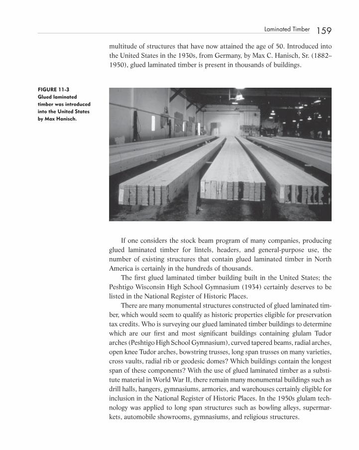
multitude of structures that have now attained the age of 50. Introduced into the United States in the 1930s, from Germany, by Max C. Hanisch, Sr. (1882 – 1950), glued laminated timber is present in thousands of buildings.
FIGURE 11-3 Glued laminated timber was introduced into the United States by Max Hanisch.
If one considers the stock beam program of many companies, producing glued laminated timber for lintels, headers, and general - purpose use, the number of existing structures that contain glued laminated timber in North America is certainly in the hundreds of thousands.
The fi rst glued laminated timber building built in the United States; the Peshtigo Wisconsin High School Gymnasium (1934) certainly deserves to be listed in the National Register of Historic Places.
There are many monumental structures constructed of glued laminated tim-ber, which would seem to qualify as historic properties eligible for preservation tax credits. Who is surveying our glued laminated timber buildings to determine which are our fi rst and most signifi cant buildings containing glulam Tudor arches (Peshtigo High School Gymnasium), curved tapered beams, radial arches, open knee Tudor arches, bowstring trusses, long span trusses on many varieties, cross vaults, radial rib or geodesic domes? Which buildings contain the longest span of these components? With the use of glued laminated timber as a substi-tute material in World War II, there remain many monumental buildings such as drill halls, hangers, gymnasiums, armories, and warehouses certainly eligible for inclusion in the National Register of Historic Places. In the 1950s glulam tech-nology was applied to long span structures such as bowling alleys, supermar-kets, automobile showrooms, gymnasiums, and religious structures.
Laminated Timber 159
c11.indd 159c11.indd 159 12/18/08 10:18:05 PM12/18/08 10:18:05 PM

160 Timber, Glulam, and Conservation
Pertinent to this, were the recent remarks of a very infl uential structural engineer during a keynote address at a symposium on the treatment of modern historic structures. He stated that modern structures were defi ned by the mod-ern materials from which they are constructed. These, according to him, are steel, glass, and concrete.
CONSERVATION OF GLUED LAMINATED TIMBER STRUCTURES
It is important for conservationists to consider the particular aspects inherent to the design and construction of glued laminated timber structures when, in the coming years, so many of these buildings will be certifi ed as historic.
Glued laminated timber is an important 20 th century building material. It can be produced in longer lengths and larger sizes than solid timber and has higher allowable design values and stiffness. Laminated timber can also be curved. The deterioration of glulam is somewhat different from that of ordinary wood, because of the glue joint. However, repair of glulam is similar to that of
FIGURE 11-4 The Peshtigo High School Gymnasium was built in 1934.
c11.indd 160c11.indd 160 12/18/08 10:18:06 PM12/18/08 10:18:06 PM
solid timber, except for that one must take into account different allowable design values, fabrication and connection techniques, and the larger sizes and special shapes common in glued laminated timber construction.
DETERIORATION
The repair or rehabilitation of glued laminated timber structures requires the expertise of a structural engineer familiar with glulam design. In order to design an appropriate repair which meets the requirements of the Secretary of the Interior ’ s Guidelines, the engineer of record must determine as much as possible about the building under investigation. This information is best found in the shop drawings. Observation and measurement is required to determine how the building has performed during its service life. Rigorous analysis is required to determine the capacity of glued laminated timber structures and how to best reinforce, repair or rehabilitate them if necessary.
Laminated timber deteriorates in the same manner as solid timber except for a few unique characteristics. Termites and fungi will destroy wood that has moisture content greater than 20 percent. In glulam, deterioration may follow certain laminations because of moisture variations. The glue line, although thin, will act as a boundary with termites found in one or two laminations for a certain distance while adjacent laminations may be free of infestation. Because laminated timber members are large, deterioration can be very serious, requir-ing intervention on a major scale.
As in other structural materials, glued laminated timber can fail due to defi ciencies in design or fabrication or changes in service conditions. Failures in glued laminated timber members can be in horizontal shear, radial tension, bending or defl ection. Horizontal shear usually occurs at connections, notched ends or highly loaded beam ends. The failure mode includes horizontal splits in the end of a member where wood fi bers slide past one another. An inade-quate glue bond can cause horizontal shear failure to occur at a glue joint.
DIAGNOSTICS AND CONDITION ASSESSMENT
The fi rst step in assessing a glued laminated timber structure is to determine species of wood, design criteria, type of adhesive, and treatments if any. If the shop drawings survive, many of these questions can easily be answered.
Shop drawings provide information such as design loads, design values, and lumber combinations, the amount of camber, building geometry, member sizes and lengths, and connection details. Concealed or hidden connections are
Diagnostics and Condition Assessment 161
c11.indd 161c11.indd 161 12/18/08 10:18:07 PM12/18/08 10:18:07 PM

162 Timber, Glulam, and Conservation
most easily determined by reviewing the shop drawings. Shop drawings are very important to the evaluation, because they refl ect what was actually built. Certain dimensions such as the tangent depths of two - hinged Tudor arches are very dif-fi cult to measure in the fi eld.
The date of construction will establish the full range of design values asso-ciated with a particular lumber combination. Many changes in design with respect to adjustments to design values or stresses have occurred since the 1930s. It is important to determine which set of design standards were used.
Waterproof adhesives usually are dark, while water - resistant adhesives are white or gray in color. Treatments, type and the amount of retention, may require that samples be laboratory tested.
By tapping with a carpenter ’ s hammer, a deteriorated glulam can be “ sounded out. “ The extent of deterioration on the surface of a member can be easily recog-nized because of discoloration. Often, termite tubes or small pinholes caused by borer insects may be visible on the surface. Ultrasonic devices may also be of value. A moisture meter can be used to determine areas likely to contain deterioration.
By measuring defl ection, members that have lost stiffness due to deteriora-tion or failure can be identifi ed.
Possible causes of damage from excessive moisture include termites and fungi. Defi ciencies in design or fabrication or changes in service conditions can cause glued laminated timber structures to fail. Horizontal shear, radial tension, bending, and defl ection are areas of investigation for the structural engineer.
CONSERVATION METHODS
Methods of conservation include reinforcement or repair with steel and epoxy systems, segmental infi ll, fi eld lamination, and steel or wood cover plates nailed, screwed, lag screwed, or bolted into place.
Damaged timber members can also be replaced. Of course, the cause of the original deterioration must be eliminated.
In North America, glued laminated timber usually consists of 1- or 2 - inch - thick (nominal thickness) Douglas fi r or southern pine boards with a waterproof adhesive applied to the face of each board. After drying, natural growth charac-teristics are removed and individual boards are end joined, with fi nger joints, to form long laminations. Individual laminations are then laid up according to a pattern and clamped under pressure until cured, forming structural members that are then dressed in a double - faced planner.
In the fabrication of glued laminated timber, the moisture content can be controlled while many strength reducing characteristics found in solid timber
c11.indd 162c11.indd 162 12/18/08 10:18:07 PM12/18/08 10:18:07 PM

members are eliminated. In the cross - section of a glulam timber, higher - grade laminations are placed in areas of high stress. For example, the bottom of a simple beam in bending will receive higher grade boards to resist tension at the extreme fi ber. So will the top of the beam cross - section more dense, straight - grained boards where higher stresses in compression are found.
Glued laminated timber allows increased freedom of design and is com-monly associated with the fabrication of large engineered wood components, which can be curved or shaped in unique ways. By gluing, timber can be fabri-cated into sophisticated structural shapes or into systems such as lamella struc-tures or geodesic domes. Tudor arches and curved tapered beams are structural components unique to glulam technology. Glued laminated timber has been used in conjunction with wire cables and fabric to form tensile structures.
Until the late 1960s, waterproof and water - resistant adhesives were both available. Various preservative pressure treatments have been used, either treat-ing individual laminations prior to gluing or the fi nished member after fabrica-tion. The most popular pressure treatment for glulam has been pentachlorophenol (in a liquid petroleum) or methylene chloride. These treatments avoid the problems of warping or checking associated with the wetting and drying process used in waterborne treatments such as Chromated Copper Arsenate (CCA).
Since its introduction into the United States in the 1930s, laminated timber has most often been a custom prefabricated construction material completely engineered by the seller. The shop drawings, submitted for the contractor ’ s approval by the laminator and reviewed by the original design team, often survive. It is very important for the architect/engineer team evaluating such structures to obtain a copy of the shop drawings. Designers often place the responsibility for the design on the laminator. Although contract documents may indicate one set of sizes and connections, the shop drawings may refl ect a “ minimum design ” with different member sizes, and a framing system optimized by the laminator.
Although laminators often destroy project fi les after a few years, depending on the legal statute of limitations, shop - drawing tracings may survive. Sometimes the owner or contractor will have a copy of the shop drawing prints. Often the original structural engineer or architect of record will have old shop drawings on fi le.
CONSERVATION TECHNIQUES
Repair and conservation techniques range from replacement in kind to rein-forcement with steel and/or epoxy systems. Many structural repairs require the replacement of the decayed ends of arches or A - frames with moment resisting steel legs connected with fi eld - applied shear plates.
Conservation Techniques 163
c11.indd 163c11.indd 163 12/18/08 10:18:08 PM12/18/08 10:18:08 PM

164 Timber, Glulam, and Conservation
The usual repair for a horizontal shear problem is to replace the member if it is badly split. Shear reinforcing of other overstressed members that have not failed may include lag screws used to “ stitch ” the beam together. These are normally inserted through the roof or fl oor deck, perpendicular to the axis of the beam. Stitch lags are inserted into pre - bored lag lead holes, which may extend almost the full depth of the beam. Three - quarter - inch diameter lag screws are available up to 30 inches in length. Other shear reinforcing may include an exposed joist hanger to support the bottom of a notched beam, steel side plates, or steel or fi ber reinforced plastic dowels inserted in vertical holes and epoxied in place with a gap fi lling epoxy formulated for wood repairs. The zone around the bored hole may be strengthened with an epoxy consolidant prior to inserting a dowel and a split member may be clamped under pressure prior to adding epoxy.
Radial tension is a failure similar to horizontal shear that occurs in the curved portion of curved tapered beams and Tudor arches. Again, the typical repair requires insertion of lag screws or reinforcing rods inserted perpendicular to the failure lines. In a curved member, insertion would be on a radial pattern.
Bending failures may require the full replacement of a member. If the fail-ure is confi ned to a few tension laminations, the glulam member can be relieved of its load by jacking. The damaged wood can then be carefully cut away. New high - quality boards obtained from a laminator, planed to the actual thickness of the exiting laminations, can be glued in place using a fi eld - applied, gap - fi lling epoxy. This work requires the skill of a craftsman and the cooperation of a glulam manufacturer who can furnish long, fi nger - joined replacement stock. Of course, the cause the failure must be removed. The repair, to be successful, may require the addition of one or more laminations to increase the depth of the member. A bending failure may require that the member be reinforced with steel side plates, bottom plates, or fl itch plates.
Any repair with steel requires that the engineer balance the load carried by steel with that carried by the glulam timber. The engineer must design the shear transfer between the two materials. Most engineers will ignore the con-tribution of the glulam and design the steel to carry the full load. In many glued laminated timber buildings, steel side plates have been painted to match the wood fi nish. If appearance is a major problem, a steel fl itch plate can be inserted into a kerf or rout cut into the center of the beam. Often, these cuts are made with a chain saw attached to a guide. The fl itch plate must then be securely attached to the wood with a suitable epoxy - bonding agent. Determining plate thickness, height, length and connection method requires a thorough struc-tural analysis. Glued laminated timber beams with inadequate bending capac-ity can also be reinforced by adding tie rods or bottom plates of steel.
c11.indd 164c11.indd 164 12/18/08 10:18:08 PM12/18/08 10:18:08 PM

Defl ection failures, cause by inadequate stiffness, usually lead to bending failures. For example, inadequate stiffness can cause excessive ponding of water on a fl at roof leading to failure bending. Of course, the most straightforward repair would be to put a lightweight tapered insulation on the roof and offset the defl ection. Most laminated timber beams are cambered to offset dead load defl ection. Excessive defl ection may indicate that a large overstress is present in existing beams due to dead load only. Certainly, on more than one occasion, cambered glued laminated timber beams have been installed up - side down.
Since glued laminated timber is a material that depends upon adhesives, epoxy repairs would be compatible with requirements of the Secretary of the Interior ’ s Guidelines. Replacement - in - kind of deteriorated laminations is rela-tively easily accomplished in the fi eld if the moisture content can be controlled and if glulam stock is available. Boards can be planed to width of the member in the fi eld after attachment.
In many glued laminated timber structures, the bases of Tudor or radial arches become deteriorated if exposed to moisture.
FIGURE 11-5 Severe deterioration is evident in the leg of a Tudor arch, which was not protected.
Conservation Techniques 165
c11.indd 165c11.indd 165 12/18/08 10:18:09 PM12/18/08 10:18:09 PM

166 Timber, Glulam, and Conservation
The connection of the laminated timber arch to its supporting steel shoe is critical because the shoe transfers vertical forces and horizontal thrust through anchor bolts to the foundation.
FIGURE 11-6 In this case, axial and bending forces are transferred to a steel leg.
Repairing this type of connection often requires that steel plates be welded to the existing shoe and connected to the glued laminated timber member to resist all forces.
FIGURE 11-7 The steel side plates transfer axial loads and bending moment to the support.
The connection of steel side plates to glued laminated timber may require the fi eld installations of 2 5⁄8 - or 4 - inch - diameter shear plates.
c11.indd 166c11.indd 166 12/18/08 10:18:09 PM12/18/08 10:18:09 PM

FIGURE 11-8 Nine sets of holes and grooves have been installed to accept 4-inch-diameter shear plates.
Shear plates are inserted fl ush to the face to the member in a dapcut by a special cutter.
Conservation Techniques 167
FIGURE 11-9 Providing a metal covering and blocking to allow moisture to escape will ensure the serviceability of the repair.
c11.indd 167c11.indd 167 12/18/08 10:18:11 PM12/18/08 10:18:11 PM

168 Timber, Glulam, and Conservation
REPLACEMENT - IN - KIND
Because laminated timber structures are composed of many components, sometimes the replacement in kind of a damaged or deteriorated beam, purlin, column or arch half span may be a more cost - effi cient solution that an in - place structural repair or reinforcing.
Often, replacement - in - kind is not economically feasible. More advances are being made in the fi eld of timber design than in any other area of structural engineering. Recent products include laminated veneer lumber and numerous other beam and joist substitutes. The most important benefi ts of these recon-stituted wood products is the availability of long lengths, higher design values, and greater stiffness. Preservationists and preservation engineers must deter-mine the appropriateness of these materials to each case.
CONCLUSION
Only through specialized knowledge and experience can structural engineers make the judgments needed to properly evaluate historic timber structures. The engineer must be convinced that the structural model in the computer is an accurate representation of actual conditions. Once that is clear, the applica-tion of rigorous analysis, testing, and engineering judgment may be necessary to explain why the historic timber structure in question has performed ade-quately for many years.
c11.indd 168c11.indd 168 12/18/08 10:18:12 PM12/18/08 10:18:12 PM

169
C H A P T E R1 2 Tabby: Engineering Characteristics of a Vernacular Construction Material *
INTRODUCTION
T T abby, like historic brick masonry, receives little attention among the general public, as well as within the construction industry. At the present time,
research funds for construction - related topics involving coastal issues fl ow toward wind design, exterior insulation systems, and the geophysical interaction of wind and ocean on shoreline development. In general, historic materials research takes a back seat to other structural engineering endeavors. A discus-sion of tabby as a construction material must always begin with a defi nition or a description, because it is unknown to most people in the construction industry.
Tabby is an early cast - in - place construction material consisting of sand, lime (from shells and wood ash), and water. Tabby can be considered a lime - based concrete, unreinforced, with shell and shell fragments serving as the coarse aggregate.
* This chapter was originally written for The Conservation and Preservation of Tabby: A Symposium on Historic Building Material in the Coastal Southeast, Jekyll Island, GA (February 1998).
c12.indd 169c12.indd 169 12/18/08 10:19:10 PM12/18/08 10:19:10 PM
Structural Investigation of Historic Buildings: A Case Study Guide to Preservation Technology for Buildings,Bridges, Towers, and Mills. David. C. Fischetti © 2009 John Wiley & Sons, Inc.

170 Tabby: Engineering Characteristics of a Vernacular Construction Material
As an unreinforced concrete product, methods used for the analysis of unreinforced concrete can be applied. As in the evaluation of any historic structure, the evaluation of tabby depends on fi eld observation and measure-ment, testing, analysis, and engineering judgment.
Historically, the quality of tabby construction was dependent on word - of - mouth tradition, as well as the quality of local materials available and the skill and knowledge of the workmen and their supervisor. The recipe, based on oral tradi-tion, usually varied from the Spanish, Portuguese, or Dutch - speaking Caribbean region to the English colonies and was infl uenced by African traditions.
TABBY MATERIALS AND PROPORTIONS
The reprint of the 1867 edition of The Encyclopedia of Architecture gives the following defi nition for concrete: Concrete is a compound of ballast, or stone chippings, and lime mixed together. It is so called from the speedy concretion that takes place between these particles. 1 Since ancient times, chemists and others have formed various opinions about the effects of sand and lime in the formation of mortar. Nineteenth - century publications detail various methods of making mortars and cements of lime. Coal cinders, furnace slag, brick dust, wood ashes, and other ingredients fi nd their way into various recipes for lime mortar.
FIGURE 12-1 Church wall at St. Helena’s Episcopal Church in Beaufort, SC is a tabby wall with a brick cap.
c12.indd 170c12.indd 170 12/18/08 10:19:11 PM12/18/08 10:19:11 PM
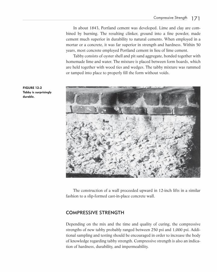
In about 1843, Portland cement was developed. Lime and clay are com-bined by burning. The resulting clinker, ground into a fi ne powder, made cement much superior in durability to natural cements. When employed in a mortar or a concrete, it was far superior in strength and hardness. Within 50 years, most concrete employed Portland cement in lieu of lime cement.
Tabby consists of oyster shell and pit sand aggregate, bonded together with homemade lime and water. The mixture is placed between form boards, which are held together with wood ties and wedges. The tabby mixture was rammed or tamped into place to properly fi ll the form without voids.
The construction of a wall proceeded upward in 12 - inch lifts in a similar fashion to a slip - formed cast - in - place concrete wall.
COMPRESSIVE STRENGTH
Depending on the mix and the time and quality of curing, the compressive strengths of new tabby probably ranged between 250 psi and 1,000 psi. Addi-tional sampling and testing should be encouraged in order to increase the body of knowledge regarding tabby strength. Compressive strength is also an indica-tion of hardness, durability, and impermeability.
FIGURE 12-2 Tabby is surprisingly durable.
Compressive Strength 171
c12.indd 171c12.indd 171 12/18/08 10:19:13 PM12/18/08 10:19:13 PM

172 Tabby: Engineering Characteristics of a Vernacular Construction Material
Samples of historic tabby, when tested, have yielded fairly good compres-sive strengths. Dr. Lauren B. Sickels - Taves tested tabby samples from the Cumberland Island National Seashore for the National Park Service. The results of the tests were as follows:
Analysis of Original Tabby:
Compressive Strength — 350 psi
Absorption — 84.58
Specifi c gravity — 2.013
Formula — 1:3:1 lime:sand:shell with wood ash
Stereology — inland beach sand
The analysis of tabby ruins or tabby buildings begins with the determination of compressive strength. A preliminary evaluation might depend on nothing more than an assumption, based on engineering judgment, for compressive strength.
TENSILE STRENGTH
Tensile strength of tabby is probably 10 to 15 percent of the compression strength. In an unreinforced tabby structure, low tensile strength would sig-nifi cantly affect serviceability. Considerable cracking would occur during both initial shrinkage and subsequent seasonal cycles in temperature.
All walls supporting lightly loaded roofs are subjected to tensile forces due to lateral loads or uplift due to wind. For this reason, the tensile strength of tabby must be determined.
Most tabby ruins are the remains of buildings that were destroyed by high winds. Presumably, the roofs of these structures were pulled off by high winds causing the collapse of some walls.
The low tensile strength of tabby and the lack of anchorage of the roof structure to resist uplift and the absence of continuous vertical ties contributed to these failures.
SHEAR STRENGTH
The shear strength of tabby is probably about 50 percent of the compressive strength, ranging from 35 to 80 percent. Shear strength must be determined when evaluating a tabby structure for lateral loads such as wind and earthquake. The model codes are beginning to mandate that suffi cient testing be undertaken
c12.indd 172c12.indd 172 12/18/08 10:19:14 PM12/18/08 10:19:14 PM

FIGURE 12-3 Typical tabby ruins, Coastal Georgia.
in historic buildings to determine the shear strength of unreinforced masonry buildings for seismic evaluation.
Although tabby is not a ductile material, seismic enhancement of tabby structures can be accomplished by increasing the ductility of the total system of walls, fl oors, and roofs acting together. By tying fl oor and roof framing to tabby walls while allowing subtle yielding of the joints between the compo-nents, the ductility of the total system can be enhanced.
STRESS – STRAIN CURVE
Concrete is usually tested by fi lling 6 - inch - diameter by 12 - inch - high cylindrical molds with concrete during job placement. These cylinders are allowed to set at the jobsite and are then transported to a testing laboratory to cure for 7 or 28 days. Out of a quantity of fi ve cylinders, two usually are tested at 7 days, two tested at 28 days, and one held in reserve. The samples are molded in accordance with ASTM C - 31 and tested in accordance with ASTM C - 39 by breaking them in a hydraulically powered compression machine that records load applied versus deformation. The strength at 28 days is the compressive strength, which is specifi ed for concrete. For example: “ 3000 psi ” concrete is actually “ 3000 psi @ 28 days ” concrete. Obviously, historic tabby cannot be sampled fresh and must be removed by being cut or cored from the structure.
Stress – Strain Curve 173
c12.indd 173c12.indd 173 12/18/08 10:19:15 PM12/18/08 10:19:15 PM
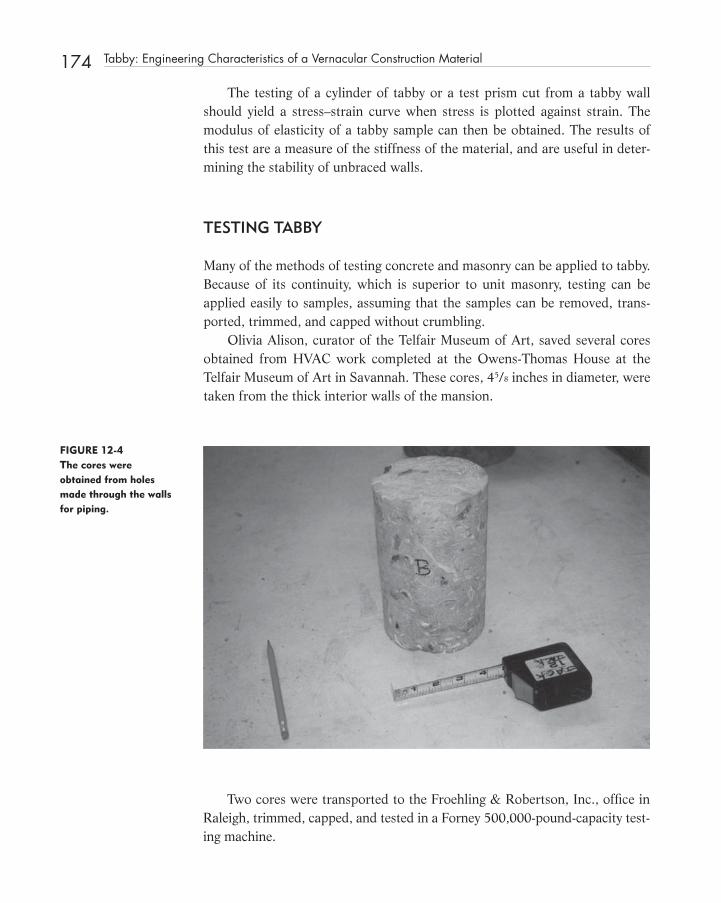
174 Tabby: Engineering Characteristics of a Vernacular Construction Material
The testing of a cylinder of tabby or a test prism cut from a tabby wall should yield a stress – strain curve when stress is plotted against strain. The modulus of elasticity of a tabby sample can then be obtained. The results of this test are a measure of the stiffness of the material, and are useful in deter-mining the stability of unbraced walls.
TESTING TABBY
Many of the methods of testing concrete and masonry can be applied to tabby. Because of its continuity, which is superior to unit masonry, testing can be applied easily to samples, assuming that the samples can be removed, trans-ported, trimmed, and capped without crumbling.
Olivia Alison, curator of the Telfair Museum of Art, saved several cores obtained from HVAC work completed at the Owens - Thomas House at the Telfair Museum of Art in Savannah. These cores, 45/8 inches in diameter, were taken from the thick interior walls of the mansion.
FIGURE 12-4 The cores were obtained from holes made through the walls for piping.
Two cores were transported to the Froehling & Robertson, Inc., offi ce in Raleigh, trimmed, capped, and tested in a Forney 500,000 - pound - capacity test-ing machine.
c12.indd 174c12.indd 174 12/18/08 10:19:16 PM12/18/08 10:19:16 PM

The core samples A and B failed at an ultimate load of 14,945 pounds, or 890 psi, and 15,499 or 923 psi, respectively.
FIGURE 12-5 The two samples were capped in similar fashion to concrete cylinders.
FIGURE 12-6 The tabby cores were tested in a 500,000-pound-capacity machine.
In situ tests that have been developed for masonry can be applied to tabby. As with masonry and concrete, obtaining accurate values for compression and shear is important. Unit weight is a physical property often overlooked, but important for analysis.
Testing Tabby 175
c12.indd 175c12.indd 175 12/18/08 10:19:17 PM12/18/08 10:19:17 PM

176 Tabby: Engineering Characteristics of a Vernacular Construction Material
WALL CONSTRUCTION
Tabby walls are proportioned so that buckling due to slenderness is not a prob-lem. Use of the basic equation for unreinforced masonry or concrete walls shows that a height to thickness ratio of 10 to 1 does not cause a reduction in strength due to slenderness. The eccentric loading due to timber trusses or large fl oor beams probably can be ignored if distributed on a thick wood plate.
Because of its relatively low strengths, tabby performs well when uniformly loaded. The support of a post or beam on a tabby wall is problematic when concen-trated loads are not distributed, such as on a wood plate or brick masonry block.
At St. Helena ’ s Episcopal Church in Beaufort, South Carolina, the brick masonry sidewalls are supported on a tabby foundation wall that is 26 inches thick. The computed design pressure for the combined dead load and live load of 6.8 psi is low when compared to the 350 psi compressive strength obtained by Sickels - Taves. In St. Helena ’ s we have a fairly uniform load. There are no cracks in the sidewalls related to settlement caused by failure in the tabby.
Stucco and plaster applied to tabby walls not only protect them but give them greater strength. A thorough analysis would include these materials in a composite section. The reapplication of these surface treatments provides an opportunity for reinforcing a tabby wall with metal lath, although corrosive environments may dictate that a stainless steel lath be used. The stucco layer can conceal earthquake or wind anchors, which may be required to tie fl oor and roof structures to tabby walls.
TABBY REINFORCING
Inset wood grounds, nailers, or plates can provide the horizontal continuity in a tabby wall capable of resisting tensile forces due to lateral loads. Often, these elements in historic structures are badly deteriorated and are in need of replace-ment. The tensile capacity of such elements is dependent on the net cross - sec-tional area of sound material, bond capacity, and continuity through joints.
SERVICEABILITY
Tabby is a surprisingly durable construction material when kept dry and free from freeze – thaw degradation.
During construction, the formula of lime, sand, shell, and wood ash mixed and placed under fi eld conditions was subject to variation. In tabby, because it is
c12.indd 176c12.indd 176 12/18/08 10:19:20 PM12/18/08 10:19:20 PM

an unreinforced lime - based cementacious product, only low strengths can be achieved compared to modern - day Portland cement concrete. It is a durable mate-rial when protected by stucco, actually hardening with time due to carbonation.
FIGURE 12-7 The Horton-DuBignon House on Jekyll Island (ca. 1738) is one of the oldest tabby structures in Georgia. (See color insert.)
FIGURE 12-8 The intersecting interior wall provides stability to the two-story Horton House ruins.
Serviceability 177
c12.indd 177c12.indd 177 12/18/08 10:19:21 PM12/18/08 10:19:21 PM
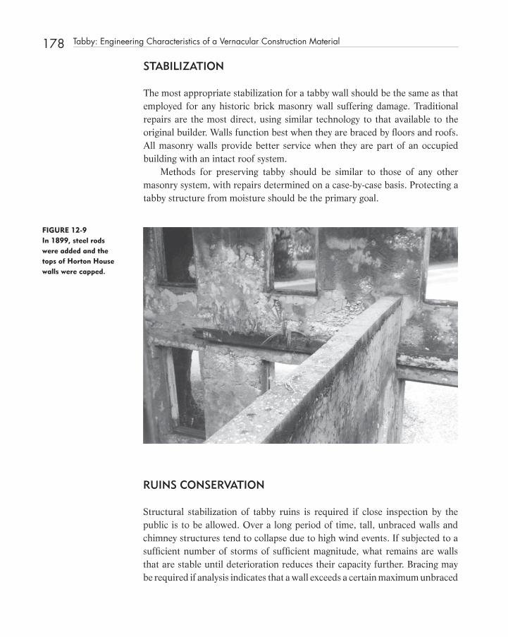
178 Tabby: Engineering Characteristics of a Vernacular Construction Material
STABILIZATION
The most appropriate stabilization for a tabby wall should be the same as that employed for any historic brick masonry wall suffering damage. Traditional repairs are the most direct, using similar technology to that available to the original builder. Walls function best when they are braced by fl oors and roofs. All masonry walls provide better service when they are part of an occupied building with an intact roof system.
Methods for preserving tabby should be similar to those of any other masonry system, with repairs determined on a case - by - case basis. Protecting a tabby structure from moisture should be the primary goal.
FIGURE 12-9 In 1899, steel rods were added and the tops of Horton House walls were capped.
RUINS CONSERVATION
Structural stabilization of tabby ruins is required if close inspection by the public is to be allowed. Over a long period of time, tall, unbraced walls and chimney structures tend to collapse due to high wind events. If subjected to a suffi cient number of storms of suffi cient magnitude, what remains are walls that are stable until deterioration reduces their capacity further. Bracing may be required if analysis indicates that a wall exceeds a certain maximum unbraced
c12.indd 178c12.indd 178 12/18/08 10:19:23 PM12/18/08 10:19:23 PM

length, which has been calculated, or if calculations indicate that suffi cient wind can be applied to overstress the free - standing wall. Because of the open nature of ruins, a free - standing wall is subject to wind forces from two direc-tions normal to its face. Analysis is similar to a sign or solid fence, using build-ing - code wind - load factors for such structures.
DESIGN AND ANALYSIS
Soil cement or terracrete requires pressure to help bind the ingredients because moisture and cement are both limited. Soil cement has been used in the manu-facture of unit masonry by ramming the mixed ingredients by hand into a mold. The design and analysis of tabby, soil cement, and adobe are similar.
CONCLUSION
Tabby is a traditional construction material important to the coastal areas of the southeastern United States and the Caribbean. Conserving historic tabby build-ings and ruins that remain will require that we undertake suffi cient research to better understand this construction material. Tabby can be analyzed in much the same way as unreinforced Portland cement concrete is analyzed. Through observation, measurement, testing, and analysis, tabby structures can be evalu-ated to determine their structural serviceability.
REFERENCE
1. Gwilt, Joseph. The Encyclopedia of Architecture, the Classic 1867 Edition, The Complete Guide to Architecture from Antiquity to Nineteenth Century. New York: Crown Publishers, 1982.
Reference 179
c12.indd 179c12.indd 179 12/18/08 10:19:24 PM12/18/08 10:19:24 PM

181
C H A P T E R1 3 Relocating the Cape Hatteras Lighthouse
INTRODUCTION
T T he relocation of the Cape Hatteras Lighthouse and dependencies involved structural issues related to lifting, transporting, and supporting the various
buildings at the new location. The International Chimney Corporation (ICC) of Buffalo, New York, won the design - build contract from the National Park Service. The relocation team included fi ve subcontracting consulting fi rms, a structural mover, and a unifi ed hydraulics system expert.
Any relocation transportation system must deal with the act of lifting the structure off the ground, transferring the load to a transport system, moving the structure along the move route, and transferring the load of the structure from the transport/support system to the new foundation.
The 208 - foot - tall brick and granite masonry tower completed in 1872 was originally constructed 1,600 feet from the shoreline.
It rested on a double layer mat of 6 � 12 southern pine timbers, laying fl at. The timber mat was located approximately 4 feet below the water table, keeping it safe from deterioration. On the timber mat rested the base of the lighthouse consisting of hard, dressed stones of pink Vermont granite grouted into place.
c13.indd 181c13.indd 181 12/18/08 10:20:04 PM12/18/08 10:20:04 PMc02.indd 15c02.indd 15 12/18/08 10:06:55 PM12/18/08 10:06:55 PM
Structural Investigation of Historic Buildings: A Case Study Guide to Preservation Technology for Buildings,Bridges, Towers, and Mills. David. C. Fischetti © 2009 John Wiley & Sons, Inc.

182 Relocating the Cape Hatteras Lighthouse
BACKGROUND
The case for moving the Cape Hatteras Lighthouse was made in a paper, by this author, titled “ Straight Line Move Necessitated by the Migration of the Barrier Islands, ” presented at the Annual APT Conference, October 1986, in Austin, Texas. That paper discussed the inevitable migration of the barrier islands, the original construction of the lighthouse, examples of other similar large build-ings moved successfully in the United States and elsewhere, and the technology available to accomplish the task.
A lighthouse is by nature obstinate and stubborn, standing as it does on the edge of the earth, subject to the ravages of the sea. When a lighthouse is threatened by time and the environment, it is popular to rally to its defense, often with the same obstinacy that the lighthouse exhibits daily. So it is with the Cape Hatteras Lighthouse in North Carolina.
This wonderful structure was designed in the 1860s painstakingly by hand, without benefi t of computers. The bricks were made and laid by hand. Beautifully
FIGURE 13 - 1 The Cape Hatteras Lighthouse is 208 feet tall. It weights 4,800 tons.
c13.indd 182c13.indd 182 12/18/08 10:20:05 PM12/18/08 10:20:05 PM

proportioned and crafted, this lighthouse has symbolized North Carolina ’ s Outer Banks for years. Now it was threatened by the relentless surf and the westward migration of the barrier island on which it stood.
By 1988, the black and white diagonally striped Cape Hatteras Lighthouse had warned mariners for 116 years of the treacherous waters that have given North Carolina ’ s Outer Banks the nickname “ Graveyard of the Atlantic. ” The Light Station at Buxton is a symbol of the Outer Banks and of maritime culture and may be the best known of American lighthouses. Because of its historical importance in the region and, indeed, the nation, the distinctive tower is included on the National Register of Historic Places. In much the same way that the structure dominates the landscape, so too is the lighthouse prominent in the local culture.
It was obvious that migration of the North Carolina barrier islands would, in time, undermine this historic structure. Dr. Orrin H. Pilkey, a Duke University geologist and noted authority on the Outer Banks, stated many times that “ the attempts to save the lighthouse in place are doomed. ”
On May 19, 1985, a Cape Hatteras Shoreline Erosion Workshop was held at Buxton, North Carolina. Participants included representatives from the National Park Service, North Carolina State University, the University of Vir-ginia, the Army Corps of Engineers, and the North Carolina Department of Natural Resources and Community Development. The purpose of the work-shop was to review the patterns and frequency of ocean shoreline changes in the vicinity of the Cape Hatteras Lighthouse.
Regardless of the database or study used, it was clear to the participants that the long - term change in this shoreline is characterized by erosion. This erosion trend appears to be consistent with changes reported for most of the mid - Atlantic coast. They concluded that causes were a combination of long - term sea level rise, storms, and both manmade and natural reduction in sedi-ment supply. The erosion of the beach was documented by reviewing 18 publications dealing with the quantifi cation of erosion and accretion. The information reviewed was based on aerial photographs and bathymetric charts for a period of 100 years. Shoreline erosion is a manifestation of the whole island changing shape and position.
Migration of the Barrier Islands is a well - documented natural condition caused by the forces of waves, tides, and wind. As the Barrier Islands roll over themselves in tank - tread fashion, nature maintains the dynamic equilibrium of the beaches through unceasing trade - offs of material, energy, topology, and the rising sea level.
For thousands of years, the traditional methods of protecting shorelines have centered around stabilizing the natural system. The construction of marine
Background 183
c13.indd 183c13.indd 183 12/18/08 10:20:06 PM12/18/08 10:20:06 PM

184 Relocating the Cape Hatteras Lighthouse
structures such as groins and jetties perpendicular to the shoreline attempt to stabilize shorelines by trapping sand carried by littoral currents running paral-lel to the shoreline. Structures constructed parallel to the shoreline, such as seawalls, bulkheads, and revetments, are built to protect a shoreline by absorb-ing the impact of the breaking waves, while breakwaters are designed to dampen wave energy before it reaches shore. Many millions of dollars have been spent replenishing or “ nourishing ” beaches by pumping new sand onto the beach or into longshore currents.
Since anything built on the beach usually increases the rate of erosion, relocation of the Cape Hatteras Lighthouse would be the preferred alternative to construction of an encircling revetment wall. Relocation of such a structure would demonstrate the feasibility of a coastal management policy that would respect the natural migration of the Barrier Islands in an area where the rapid development of permanent structures is sure to lead to disaster. The long - term history at Cape Hatteras has been shoreline erosion at an average of approxi-mately 11 feet per year.
More than 1,200 shipwrecks have occurred in the waters off Cape Hatte-ras since the fi rst recorded wreck in 1526. Hatteras is the point where two major ocean currents off the east coast, the northbound Gulf Stream and the southbound remnant of the Labrador Current, collide head on. This collision causes constant turbulence of Cape Hatteras, which has resulted in the forma-tion of a shifting mass of underwater sand bars that stretch eastward into the Atlantic from the cape for some 14 miles, creating Diamond Shoals, dreaded by mariners the world over.
Congress heeded the call of coastal captains for navigational aids specifi -cally designed to assist offshore vessels by passing an act in 1794 that provided for the drafting of construction plans for a fi rst - rate lighthouse to be built at Cape Hatteras. The fi rst Cape Hatteras Lighthouse was a 90 - foot high, octago-nal shaped, sandstone structure completed in 1802.
In 1850, complaints to a newly formed Light House Board regarding the inadequacy of the Cape Hatteras light were heard. The light was inadequate to be seen a great distances, and the tower was not tall enough to penetrate a blanket of haze that formed over nearby Diamond Shoals and the cape itself.
In March 1867, Congress appropriated $ 75,000 for the construction of a new lighthouse at Hatteras. The Light House Board insisted that ” (in) a tower so exposed as the new one proposed for Cape Hatteras, it is desirable to take every measure to secure the very best materials. ” 1 The materials included one million “ prime dark red brick ” at a cost of $ 12.35 per thousand supplied by Nicholas M. Smith of Baltimore. The brick and stone for the foundation were transported by schooners or shallow - draft steamers to a point in the open
c13.indd 184c13.indd 184 12/18/08 10:20:06 PM12/18/08 10:20:06 PM

sound where materials were transferred to lighters. These scows could not get all the way to shore, so a long wharf had to be built into the sound. A tram railway was constructed from the wharf to the construction site to transport building materials over mucky marsh and soft sand.
David Stick, in his book North Carolina Lighthouses , describes the laying of the foundation of the Cape Hatteras Lighthouse. 1
Instead of contracting with a private fi rm for the project, the Light House Board took on the job with its own crew, hired a foreman, and employed day labor, all under the general direction of a district engineer. The foreman selected for the Cape Hatteras project was Dexter Stetson, a man ingenious enough to fi gure out new ways of getting things done and capable of doing them.
Dexter Stetson ’ s working party was on the job in early November 1868. Construction began on quarters and a messroom for the crew, a blacksmith shop, two derricks, and storage buildings for cement and other perishable materials, as well as the wharf, tram railway, and scows.
Because the lighthouse was to be constructed on a relatively low beach covered with soft sand, there was special concern about the foundation. Origi-nal plans had called for driving heavy pilings into the sand as support for the huge blocks of granite that were to serve as a base for the tower, but Stetson found that he could a drive a sounding rod only 9 feet into the sand. He then discovered one of those contradictions of nature that coastal residents tend to take for granted. The very same sand that is so dry and soft near the surface that a man ’ s foot will sink to a depth of an inch or two with every step is almost invariably damp and compact only a couple of feet down. It thus forms an exceptionally sturdy foundation capable of supporting tremendous weight. 1
Accordingly, Stetson proceeded to excavate a wide hole 6 feet deep. Find-ing that he could drive the pilings only 6 more feet below that level as a result of “ the sand being very hard and compact, ” he devised an entirely different method of supporting the structure. Because his 6 - foot hole had rapidly fi lled with water, he took advantage of another phenomenon of nature: the resist-ance of certain types of wood to decay so long as they are totally submerged in water and thus not exposed to the air. By building a cofferdam around his huge hole in the sand, he was able to keep the hole free of water with the use of “ powerful steam engines. ” He then laid a course of 6 - by - 12 - inch southern pine timbers in the bottom of the hole and placed a second course of 6 � 12s cross-way on top of the fi rst layer. Using the timbers as a base, he then “ laid a mas-sive octagonal foundation, composed of large blocks of granite laid in cement mortar, a rubble masonry, the interstices being fi lled with smaller stone of the same kind. ” 1 When this was done, he turned off the steam engines and let the water seep back into the hole, covering the pine timbers. 1
Background 185
c13.indd 185c13.indd 185 12/18/08 10:20:07 PM12/18/08 10:20:07 PM
186 Relocating the Cape Hatteras Lighthouse
From the ground level, four more octagonal courses of cut granite were added, each narrower than the preceding one, thus giving the outward appear-ance of huge stone steps surrounding the exposed foundation. Above this foun-dation for a height of approximately 10 feet cut granite was laid at each corner with solid brick between, thus providing a base suffi cient to support the weight of the massive circular brick tower that was to rise above it.
As the crew of masons continued to lay course after course of brick, grad-ually reducing the diameter of the tower as they worked skyward, metal stair-ways were installed. When at last the structure was completed, the Light House Board shipped down a fi rst - order fl ashing lens of the most modern design with a lampist named George J. Crossman to install it properly.
The current tower, round and 208 feet tall, was completed 600 feet north of the original 1802 sandstone structure and 1,600 feet from the shoreline; the older light was demolished. Yet by 1919, the shoreline had eroded to within 300 feet of the second tower. In an effort to arrest the trend, the Lighthouse Service installed 900 linear feet of interlocking groins in 1930. Within two years, though, the shoreline was 100 feet from the light station, prompting the construction of more groins, which also proved ineffective.
In 1935, land was acquired for a new light station, and a metal frame tower 150 feet in height was completed the following years. Upon exhibiting the new light, the 44 acres comprising the old site were turned over to the Department of the Interior for use by the National Park Service.
In the following decade, the erosion was reversed by accretion along the shoreline. As a result, in 1950 the National Park Service and the Coast Guard entered into an agreement that allowed the light to be moved back to the striped tower. Basically, the agreement specifi ed that the National Park service controls the light station, while the Coast Guard was obligated to take appro-priate action to maintain a light, whether in the tower or elsewhere.
Since 1950, though, erosion rather than accretion had affected the coast in the vicinity of the station, and again the Cape Hatteras Lighthouse was threat-ened with destruction by the sea.
In 1979, the National Park Service commissioned a study for the feasibility and cost estimate for relocating the lighthouse. 2 The proposed method called for the relocation of the complete light station to an area 2,800 feet southwest from its present site. Two keeper ’ s quarters and an oilhouse would be relocated along with the 2,600 - ton lighthouse. For that study, MTMA Design Group of Raleigh, an architectural fi rm, hired the author to provide consulting structural engineering services to assist in determining the means and methods of such a relocation and assist in the cost estimating. Previously in 1978 we had provided consultation to MTMA Design Group for a similar study for the Cape Lookout
c13.indd 186c13.indd 186 12/18/08 10:20:07 PM12/18/08 10:20:07 PM

Lighthouse which was also threatened by erosion. 3 For the Cape Lookout study we naively concluded that the lighthouse could be cut into four to fi ve pieces to be moved separately. It was obvious that for the Cape Hatteras Lighthouse there would have to be another approach because the base alone weighed more than 700 tons.
The 208 - foot - tall lighthouse is a brick masonry cylinder enclosed by a trun-cated cone. The inner and outer walls are connected by numerous shear walls. The center of gravity of the lighthouse is only 56 feet above the base. Propor-tioning the lighthouse with a low center of gravity enables it to withstand high wind forces tending to overturn such a tall structure. Its inherent stability against overturning is critical to the feasibility of relocating this massive struc-ture in one piece.
Because of economics, the relocation of very large masonry structures is usually made in a straight line or along a smooth horizontal curve on fi xed rails. Even though the lighthouse was at that time estimated to weigh 2,600 tons above grade, it was more feasible to move the structure in one piece rather than several. The cylindrical tower could have been cut into manageable sections, but the octagonal base, weighing 768 tons, would remain a very heavy piece to relocate intact. Thus, the proposed method to move the lighthouse in its entirety, in a straight line, along steel and concrete rails to a new foundation was judged to be a more simple and practical solution once the structure is lifted from its foundation.
The new site, as selected by the National Park Service for the relocation study, would be 2,800 feet southwest of the current site and 2,400 feet from the shoreline. Factors infl uencing site selection include soil - bearing capacity and water table depth, elevation and stability of the landscape, number of years before coastal erosion again would affect the structure, and ease of moving across the intervening landscape.
To lift the lighthouse from its foundation, we proposed that heavy - steel needle beams would be horizontally inserted in two directions through the octagonal base. The beams would be connected to steel girders, forming a square in plan; numerous struts would brace the girders to each other. The structural steel would weigh an estimated 150 tons, with the largest piece weighing 33 tons. 2
The lighthouse, along with the steel framework, would then be raised by twenty - two 150 - ton hydraulic jacks. Suffi cient cutting of brick and stone would be required to ensure a relatively clean separation from the foundation, which would then be relocated to the new site.
The proposed procedure would require that two parallel rails be con-structed to the new site. The rails would consist of 1 ¼ - inch continuous steel
Background 187
c13.indd 187c13.indd 187 12/18/08 10:20:07 PM12/18/08 10:20:07 PM

188 Relocating the Cape Hatteras Lighthouse
plates bearing, on concrete grade beams, on a wide band of sand stabilized with Portland cement.
Upon visiting the structure on September 13, 1986, Mr. Kenneth Adair, a building mover contractor from Boynton Beach, Florida, stated to this author that there is “ no question ” that the Cape Hatteras Lighthouse can safely be moved.
FIGURE 13-2 Kenneth Adair (right) consulted with the author in September 1986.
The solution proposed by Mr. Adair would require that fi ve to six parallel rails be construction to spread the weight of the moving load more evenly on the supporting sand layers below. This discussion validated the assumptions we made regarding the feasibility of location made seven years before.
Machinery available to move a large masonry structures include hydraulic cylinder jacks, industrial rollers, and cable pulling machines to provide the force needed to overcome static friction at the initiation of movement and to sustain a constant rate of movement.
The Simplex Division of Templeton, Kenly & Company of Broadview, Illinois, had been manufacturing high tonnage hydraulic cylinders for 40 years.
c13.indd 188c13.indd 188 12/18/08 10:20:08 PM12/18/08 10:20:08 PM
Simplex/Pine hydraulic cylinders are available from stock in capacities, ranging from 150 to 500 tons with piston travels from 3 to 12 inches. Higher capacities and longer travels can be engineered into the hydraulic cylinder jacks. High - tonnage hydraulic cylinder jacks, manufactured by many companies, have been used in countless applications throughout the world for many years. 4
Hillman Incorporated, of Wall, New Jersey, manufactures large industrial rollers with load capacities of 300 to 500 tons per unit. Constructed of hard-ened steel, these rollers can move very heavy loads with a 5 percent coeffi cient of friction between bearing surfaces. 5
The Lucker Manufacturing Company is a division of the American Hoist and & Derrick Company Manufactures Pulling Machines, which pull wire rope with a continuous, steady, smooth motion. The hydraulic power unit, powered by electric motor, gasoline, or diesel engine, can exert pulling up to one million pounds at a normal speed of 3 feet per minute. Pull machine controls provide for precise and full control of the pulling operation. A direct reading calibrated gauge tells the operator the actual pounds or kilograms pulling on the wire rope at all times. Force of pull and speed are fully adjustable from zero to maximum. It was obvious that the equipment required to accomplish the task was available in several forms by many vendors.
The physics involved in the horizontal moving of any object is rather sim-ple. In the horizontal direction, the force required to produce movement is a function of the mass of the structure and the acceleration required to overcome the friction forces between the surface of the rollers and the rails. In other words, in the case of the Cape Hatteras Lighthouse, a 130 - ton force would be required to move the 2,600 - ton structure from a stationary position to a very slow velocity in the horizontal direction.
The stability of the lighthouse is a question of simple statics. In the vertical direction, the underlying sands will “ push up ” with an opposite force equivalent to the weight of the lighthouse, thus providing stability in the vertical direction. This is no problem as the underlying geology is composed of very dense sands.
The overturning forces imposed on the lighthouse due to small horizontal accelerations during the moving operation would be insignifi cant compared to the overturning forces produced by a 120 mph wind. The overturning stability of the lighthouse is excellent because its proportions were determined to spe-cifi cally resist horizontal wind load forces.
The successes, for many years, of building movers in the United States is well documented in such periodicals as Scientifi c American, Engineering News Record, and House and Building Mover magazine.
In 1923 the fi rm of John Eichleay, Jr., Company, of Pittsburgh, Pennsylvania, moved the 3,200 - ton St. Nicholas Roman Catholic Church on East Ohio Street in
Background 189
c13.indd 189c13.indd 189 12/18/08 10:20:08 PM12/18/08 10:20:08 PM

190 Relocating the Cape Hatteras Lighthouse
Pittsburgh, a distance of 20 feet. The church consisted of heavy brick walls with timber - framed fl oors and roof structure. The building measured 110 feet by 65 feet with two towers fl anking the narthex. The contractor utilized 85 - pound steel rails, 3 - inch rollers, and numerous screw jacks, as well as a considerable amount of tim-ber cribbing and “ running timbers. ” There was no interruption in the use of the building and no damage to the delicate plaster or stained glass windows. 6
This same contractor, in 1903, moved the 600 - ton Col. Brown mansion 160 feet vertically from the banks of the Monongahela River in Pittsburgh to the top of the bluff overlooking the river.
FIGURE 13-3 The Col. Brown Mansion was moved in Pittsburgh, Pennsylvania, in 1903.
The brick house measuring 85 feet by 40 feet was lifted in stages to four benches cut into the face of the cliff. Again, the technology was similar, utilizing steel needle beams, screw jacks, and timber cribbing. 7
More recently, in 1975, the sixteenth - century Church of the Virgin Mary at Most, Czechoslovakia, weighing 12,000 tons, was moved because it prevented access to large underground coal deposits. It was moved 800 yards on rails at 0.0013 mph over a period of 4 weeks at a cost of $ 15,300,000.
c13.indd 190c13.indd 190 12/18/08 10:20:09 PM12/18/08 10:20:09 PM

FIGURE 13-4 The Church of the Annunciation of the Virgin Mary, Most, Czech Republic.Source: Courtesy of the City of Most, Michal Hornof.
FIGURE 13-5 The Church of the Virgin Mary moved along a curved route.Source: Courtesy of the City of Most, Michal Hornof.
In 1966, the 3,200 - year old Temples of Ramesses II, at Abu Simbel in Egypt, were moved to site 212 feet above and 690 feet back from the approaching shore-line of Lake Nasser. Italian engineers, in 1965, proposed to move each of the temples in a single piece. One weighing 291,500 tons and the other 60,500 tons.
Background 191
c13.indd 191c13.indd 191 12/18/08 10:20:10 PM12/18/08 10:20:10 PM

192 Relocating the Cape Hatteras Lighthouse
The estimated cost for this proposal was $ 90 million. Alternatively, the temples were cut into 950 pieces weighing 30 tons or less. The relocation effort that res-cued these ancient structures was chronicled in the May 1966 issue of National Geographic in an article titled “ Saving the Ancient Temples at Abu Simbel. ” 8
FIGURE 13-6 The Temples of Ramses were moved in 1966.Source: Courtesy of Denise Chan’s Flickr stream, Creative Commons License Attribution-Share Alike 2.0 Generic.
The relatively simple structure of the lighthouse and its location are two aspects that contribute to the technical feasibility of relocation. It is not an ancient structure. Detailed plans showing the construction of the lighthouse are fi led with the Coast Guard in New London, Connecticut. 9
We argued that the relocation of the Cape Hatteras Lighthouse would be benefi cial to the State of North Carolina in terms of tourism not only during the moving operation, but also thereafter; the value of the lighthouse as a historic site would be enhanced because this would be the lighthouse that was “ moved. ” It would have an impact on our policy regarding coastal management and zon-ing that would recognize the migrating nature of the barrier islands and the feasibility of relocating large structures.
The philosophy/argument that if a structure is moved its historic signifi -cance is compromised was invalid here. To the contrary, the revetment is a traditional “ hold back the sea ” approach, which denies the migrating nature of the barrier islands. It would have permanently changed the site, creating within 50 to 70 years a new island, restricting access, and obscuring the view of the
c13.indd 192c13.indd 192 12/18/08 10:20:11 PM12/18/08 10:20:11 PM
lighthouse. Building a wall is a primitive, expensive, and ultimately futile attempt to save the lighthouse because when the island itself is undercut by the sea, there will be no more alternatives. In this case, moving the lighthouse 1,000 yards preserved its historic setting among the dunes, with its outbuild-ings surrounding it, for at least 200 years. It was a valid approach, since the technology to move it was readily available. This was a project worthy of national attention and of size suffi cient to demonstrate new approaches to preservation. We were concerned about having our preservationist ideals entrenched within the bureaucracy to such an extent that valid, economical solutions are ignored to the detriment of the structure. In an amazing reversal, the National Park Service embraced the idea of relocation as the best solution for saving the Cape Hatteras Lighthouse.
It was important that the citizens of the United States to have an opportunity to save the Cape Hatteras Lighthouse in a manner that would result in the least amount of disruption, the most permanent solution, and the lowest possible cost.
The Move the Lighthouse Committee, a small, nonprofi t, group dedicated to the relocation of the Cape Hatteras Lighthouse, was created shortly after the National Park Service announced that it intended, with the U.S. Army Corps of Engineers as consultant, to build a seawall revetment to protect the light-house in place. During a jobsite visit in Raleigh I mentioned to Barrett Wilson that the proposed revetment wall would not work, and that furthermore, I knew that relocation was feasible because, as consultant to MTMA, we had determined that the cost for relocation was estimated to be 2.74 million dol-lars. Barrett thought that we should organize an effort to pressure the National Park Service to reverse their decision. We wrote many letters to the National Park Service, the US Army Corps of Engineers, and our elected offi cials and infor-mally published the document “ Move It or Lose It! ” This organization, consist-ing of Barrett Wilson of Raleigh, North Carolina, David M. Bush, formerly of Duke University, Dr. Orrin Pilkey of Duke University, and this author began to lobby against the seawall revetment, and for relocation. In 1988, the Park Service revisited its decision with the assistance of the National Research Council ’ s Committee on Options for Preserving Cape Hatteras Lighthouse. The National Research Council ’ s agreed with the Move the Lighthouse Com-mittee and selected relocation as the preferred option.
DESIGN ISSUES
The Park Service fi rst solicitated design proposals for the relocation of the Cape Hatteras Lighthouse. We participated in the brainstorming part of that effort and our team was selected for the project. During the design proposal
Design Issues 193
c13.indd 193c13.indd 193 12/18/08 10:20:13 PM12/18/08 10:20:13 PM

194 Relocating the Cape Hatteras Lighthouse
our team considered, and then quickly rejected, two possible alternatives for primary elements of the project. First, we considered the idea that the light-house required a gantry or bracing structure to provide stability during trans-port. We reasoned that by its inherent service as a navigational aide, subjected to high wind forces, the lighthouse is proportioned to be highly stable and thus did not require a supplemental bracing structure. Our analysis showed that the factor of safety against overturning, in a 120 mph wind, was at least 17 to 1. At no point in a 120 mph wind does the lower portion of the windward side of the masonry structure develop tensile forces due to overturning. We estimated that a stiff gantry structure of steel would weigh at least 200 tons. Construction of such a tower would negatively affect the schedule and the budget with little or no benefi t in return. Unfortunately this project did not move forward because the funding was not in place.
The selected alternative in the International Chimney Corporation design - build proposal consisted of steel cross beams, main carrying beams, and a steel cradle at the base of the lighthouse. This is the critical area that must be con-tained while a controlled application of force is applied to the bearing surfaces at the lift points. Our team considered and rejected the idea that a continuous hard rail system had to be built along the total length of travel. We instead agreed that a set of steel rails and a steel mat which would be advanced in leap - frog fashion along the route would have many advantages. For strength, ease of handling, availability, and salvage value, a mat consisting of W10 � 54 steel beams was selected.
LIFTING THE LIGHTHOUSE
The ICC team considered separating the lighthouse at the fl oor level, at mid - height of the base above grade, and below the base of the lighthouse. Interna-tional Chimney Corporation rejected all alternatives in favor of lifting the lighthouse from several feet below grade. Separating the lighthouse at fl oor level was rejected because it would require considerable rehabilitation of brick and stone and separate the work into essentially two large moves. The second alternate was rejected for the same reason. Although work would be more effi cient above grade, the cost for rehabilitation of the stonework and brick masonry above grade would negatively impact the project. A lift of the total structure from below the base was also rejected because of the much greater weight involved, the large vertical distance for the lift, and the expense of working below the water table. Although the total lift alternative is an attrac-tive possibility because of the retention of historic fabric, the overall cost
c13.indd 194c13.indd 194 12/18/08 10:20:13 PM12/18/08 10:20:13 PM

would be 30 to 50 percent greater than the selected scheme. The selected alternative allowed us to perform the majority of work between grade and the water table. Cutting through the base with a cable saw provided an opportu-nity to observe conditions within the stone base and mitigate adverse condi-tions prior to the lift.
The builder, Dexter Stetson, did an exceptional job of placing and grouting the Vermont granite stones. Cable saw cuts by International Chimney revealed a solid, well - grouted base consisting of large semidressed granite blocks. Com-pressive strength tests made of cores obtained from the granite were in the 16,000 psi range. So hard was the granite that cutting through the base required much more time than originally scheduled.
The ICC team considered and rejected a deep foundation for the rail sys-tem as unnecessary. Preliminary soil borings indicated that hard stiff sands are fairly close to the ground surface. We agreed that the most cost - effective approach was to mitigate the loose soils utilizing vibratory compaction meth-ods. This technique provides a wide path of uniformly dense sands. We rejected the deep pile solution because of the variable support provided in the system. Hard supports at pile locations would have contrasted with intermediate sup-port points, depending on the stiffness of the grade beams that would have to span between. The cost of grade beams to span even short distances would be prohibitively high. The cost for the removal of piles after construction would also negatively affect the schedule and budget.
We also considered, and then rejected, a new foundation supported by piles. Again, the presence of near surface dense sands made a deep foundation unnec-essary. Our team agreed that the original builder Dexter Stetson ’ s method of building a raft or mat as support for the lighthouse was the most cost - effective alternative. He utilized a double mat of 6 � 12 southern pine timbers as support for a granite base of large, semi - dressed stones grouted in place.
Jobsite inspection, monitoring, and testing services for the lighthouse relocation included geotechnical engineering associated with the rail support system along the relocation alignment and at the new relocated lighthouse site, as well as testing and inspection services during the preparation and construction of the rail system and the new lighthouse foundation site, and also continuous monitoring of the stress and strain within the structure during the actual move.
Field and laboratory testing by Law Engineering and Environmental Services Inc. (MACTEC) was presented in a geotechnical report describing the fi ndings of the investigation. Included were recommendations for subgrade preparation and foundation support along the route and at the new lighthouse location. The pro-cedures for subgrade preparation, along with subgrade performance during the
Lifting the Lighthouse 195
c13.indd 195c13.indd 195 12/18/08 10:20:14 PM12/18/08 10:20:14 PM

196 Relocating the Cape Hatteras Lighthouse
relocation, were addressed. The geotechnical investigation for the new lighthouse location included recommendations for site preparation and requirements for foundation support.
Full - time testing and inspection was required in order to verify the conti-nuity of subsurface conditions indicated in the geotechnical report and to mon-itor construction activities to verify that adequate foundation subgrade conditions were achieved. In addition to monitoring of the subsurface condi-tions, on - site geotechnical personnel provided in - place density tests of sub-grade soils.
The on - site monitoring provided information, on a continuous basis, to on - site personnel as to the motion and strains to which the lighthouse was being subjected and issue warnings if the established parameters had been approached or exceeded. Data was also compiled at three locations for various team members in Buffalo, Chicago, and Atlanta.
ROUTE PREPARATION
After excavation and dewatering, the base of the lighthouse was “ mined ” by cutting through with a stone cutting cable saw.
FIGURE 13-7 After the excavation, of the original foundation had to be dewatered.
c13.indd 196c13.indd 196 12/18/08 10:20:14 PM12/18/08 10:20:14 PM
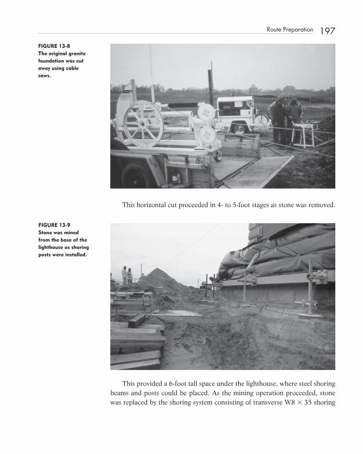
FIGURE 13-8 The original granite foundation was cut away using cable saws.
This horizontal cut proceeded in 4 - to 5 - foot stages as stone was removed.
FIGURE 13-9 Stone was mined from the base of the lighthouse as shoring posts were installed.
This provided a 6 - foot tall space under the lighthouse, where steel shoring beams and posts could be placed. As the mining operation proceeded, stone was replaced by the shoring system consisting of transverse W8 � 35 shoring
Route Preparation 197
c13.indd 197c13.indd 197 12/18/08 10:20:15 PM12/18/08 10:20:15 PM

198 Relocating the Cape Hatteras Lighthouse
beams and 5 - inch - diameter, double extra strong, shoring posts on heavy bear-ing plates supported by one layer of 6 � 8 oak cribbing.
FIGURE 13-10 A steel mat was installed to support the pipe column shoring posts.
Supporting the oak cribbing was a continuous steel mat of W10 � 54s that rested on the original timber mat. The 70 - foot - long steel mats were inserted fi rst. After the cribbing and plates were placed, the shoring posts were installed, spaced 4 foot on center in one direction and 4 foot, 6 inches on center in the other direction. After installing cross - bracing angles, the W8 � 35 shoring beams were installed on top of the posts. Built into each post was a Simplex ™ 50 - ton hydraulic jack with a 10 - inch stroke. As each section was completed, the hydraulic jacks were pressurized to support their share of the total weight transferred to the shoring steel, the next section was sawed through, and the stone removed. Steel mats, cribbing, bearing plates, posts, and shoring beams followed the mining of each section until the lighthouse was supported on steel in its entirety.
Heavy cross steel consisting of 60 - foot - long W14 � 145 beams were inserted parallel to and between the shoring beams. Gaps above the shoring beams were grouted and shimmed. Below the 13 cross beams, seven main beams consisting of seventy, 72 - foot - long double W24 � 162 beams were inserted transverse to the shoring steel and parallel to the move direction. The main beams contained inverted hydraulic cylinders that rested on Hillman ™ indus-trial rollers. This assembly was the heart of the system. Repeated 100 times,
c13.indd 198c13.indd 198 12/18/08 10:20:16 PM12/18/08 10:20:16 PM

the 100 - ton hydraulic jacks had more than suffi cient capacity to support the lighthouse during the move.
The lighthouse was lifted in stages using the synchronized hydraulic system. After the cylinders were suffi ciently extended, 6 � 8 oak cribbing was installed as a temporary support. The load was transferred from the jacks to the cribbing, and then the posts, jacks, and plates were reset at higher elevation on additional cribbing. In this manner the lighthouse was lifted out of its original excavation to a height that would allow it to move horizontally on the track of densifi ed soils, stone subbase, steel mats, and track beams. Five hydraulic push jacks con-nected to the track beams and the double main beams were used to propel the lighthouse and its supporting steel. Each push jack was connected to a track beam with a hydraulic clamp. The 4,800 tons quietly moved along the tracks, pushed in 4 - to 5 - foot increments. After the push jacks were extended, the hydraulic clamps would release to allow the push jacks to retract for the next push. As the mat and track steel were passed over and cleared, these items were picked up and relocated in front of the lighthouse. This “ leapfrogging ” of stone and steel was the limiting factor to the rate of travel for the lighthouse.
FIGURE 13-11 The main steel “leapfrogged” along the route to the new site.
Moving the lighthouse from the prepared travel route onto the new foun-dation essentially reversed of the process used to move it off the old founda-tion. A transition zone of stepped cribbing was used to carry the track steel across the new foundation.
Route Preparation 199
c13.indd 199c13.indd 199 12/18/08 10:20:17 PM12/18/08 10:20:17 PM

200 Relocating the Cape Hatteras Lighthouse
Once the correct position was reached, a sequential operation of placing steel support columns between the cross steel to the foundation allowed for the removal of the track beams and main beams. Support columns were installed while the lighthouse was still elevated; setting the lighthouse to its proper ele-vation, and allowing the columns to support the load of the lighthouse, while the support frame was sequentially dismantled from the mains down.
FOUNDATION DESIGN
Eighty percent of the weight of the lighthouse was estimated to lie within a donut - shaped footprint. This load pattern was used to distribute the weight to the shoring beams and towers, cross beams and main steel, and the new foun-dation. The new foundation was proportioned by applying the load from the lighthouse in three stages across the footing. The Portland Cement Association concrete design software PCA - Mats ™ was used to check footing thickness and reinforcing quantities. Although the original footing mat had been a double criss - cross layer of 6 � 12 dense southern pine timbers, laying fl at, the new foundation was 60 feet wide to accommodate the moving system. It was designed to subgrade parameters provided by the geotechnical consultant. Footing thicknesses reviewed included 36, 48, and 60 inches. Final parameters used for design consisted of a subgrade modulus (Ks) of 50 kcf and an allowable
FIGURE 13-12 The Lighthouse was lifted out of its original position to the proper grade.
c13.indd 200c13.indd 200 12/18/08 10:20:18 PM12/18/08 10:20:18 PM

soil bearing pressure (Qa) of 6,000 psf. Analysis indicated that a 48 - inch thickness provided a balanced design between concrete and reinforcing steel with a comfortable factor of safety in bending and shear for the various loading conditions during and after the move.
FIGURE 13-13 The new founda-tion consisted of a 4-foot-thick reinforced concrete mat 60 feet square in plan.
NEW FOUNDATION
The original timber mat provided satisfactory support for over 125 years. Available soils data, experience, and testing in the Buxton area indicated that soil conditions at the new location were very similar to those at the original location. A concrete mat foundation 4' - 0 " thick by 60' - 0 " square was designed to distribute the weight of the lighthouse uniformly across a wide area with the least amount of internal stress in the foundation structure. The foundation mat was proportioned to impart relatively low stresses to the underlying soils. Because the load of the lighthouse was applied nonuniformly to the new con-crete mat as the lighthouse was moved onto it, the new mat contained addi-tional reinforcing to accommodate the changing stress pattern.
Reinforcing consisted of epoxy coated #10 (1 ¼ - inch diameter) bottom bars spaced at 8 inches on center each way and #10 reinforcing bars spaced at 14 inches on center each way in the top of the mat. Strips through the middle of the footing had additional reinforcing to accommodate bending stresses imparted
New Foundation 201
c13.indd 201c13.indd 201 12/18/08 10:20:19 PM12/18/08 10:20:19 PM
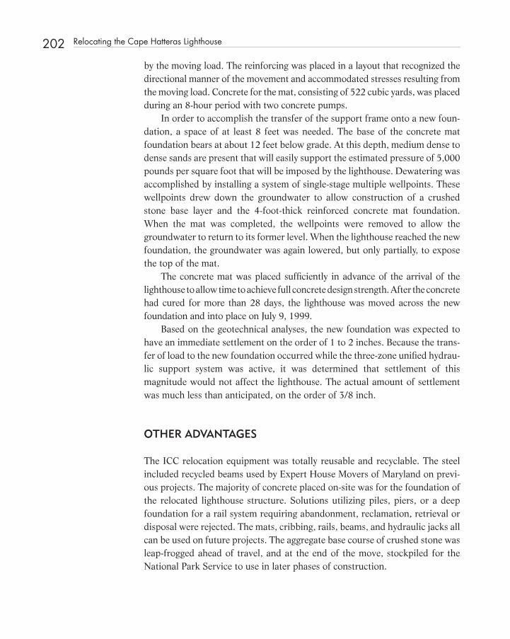
202 Relocating the Cape Hatteras Lighthouse
by the moving load. The reinforcing was placed in a layout that recognized the directional manner of the movement and accommodated stresses resulting from the moving load. Concrete for the mat, consisting of 522 cubic yards, was placed during an 8 - hour period with two concrete pumps.
In order to accomplish the transfer of the support frame onto a new foun-dation, a space of at least 8 feet was needed. The base of the concrete mat foundation bears at about 12 feet below grade. At this depth, medium dense to dense sands are present that will easily support the estimated pressure of 5,000 pounds per square foot that will be imposed by the lighthouse. Dewatering was accomplished by installing a system of single - stage multiple wellpoints. These wellpoints drew down the groundwater to allow construction of a crushed stone base layer and the 4 - foot - thick reinforced concrete mat foundation. When the mat was completed, the wellpoints were removed to allow the groundwater to return to its former level. When the lighthouse reached the new foundation, the groundwater was again lowered, but only partially, to expose the top of the mat.
The concrete mat was placed suffi ciently in advance of the arrival of the lighthouse to allow time to achieve full concrete design strength. After the concrete had cured for more than 28 days, the lighthouse was moved across the new foundation and into place on July 9, 1999.
Based on the geotechnical analyses, the new foundation was expected to have an immediate settlement on the order of 1 to 2 inches. Because the trans-fer of load to the new foundation occurred while the three - zone unifi ed hydrau-lic support system was active, it was determined that settlement of this magnitude would not affect the lighthouse. The actual amount of settlement was much less than anticipated, on the order of 3/8 inch.
OTHER ADVANTAGES
The ICC relocation equipment was totally reusable and recyclable. The steel included recycled beams used by Expert House Movers of Maryland on previ-ous projects. The majority of concrete placed on - site was for the foundation of the relocated lighthouse structure. Solutions utilizing piles, piers, or a deep foundation for a rail system requiring abandonment, reclamation, retrieval or disposal were rejected. The mats, cribbing, rails, beams, and hydraulic jacks all can be used on future projects. The aggregate base course of crushed stone was leap - frogged ahead of travel, and at the end of the move, stockpiled for the National Park Service to use in later phases of construction.
c13.indd 202c13.indd 202 12/18/08 10:20:20 PM12/18/08 10:20:20 PM

The transportation scheme designed by the ICC team provided system redun-dancy. No other system offers a comparable safety margin and system redundancy as the selected design. With regard to weight variables, inconsistencies in the move route, protection against storms, and variations in subgrade support, a hydraulic system on steel rails was judged the best solution for moving the Cape Hatteras Lighthouse.
FIGURE 13-14 The Lighthouse was moved on steel rails.
SUMMARY
The relocation of the Cape Hatteras Lighthouse utilized technology known to few people, mostly in the structural moving industry, to lift, transport, and set the 4,800 - ton lighthouse. The unifi ed hydraulic system allowed the structure to be uniformly supported while traversing a support system consisting of beams, mats, and compacted soils. Structural issues involved vertical support of the lighthouse as its base was incrementally removed by mining, support during transport by a system of cross beams and main beams, and temporary and permanent support at the new location. The inherent stability of the lighthouse dictated that once supported on steel the lighthouse would remain stable. The 5 - inch double extra strong steel pipe shoring towers had to be laterally braced to resist wind and seismic forces.
Summary 203
c13.indd 203c13.indd 203 12/18/08 10:20:20 PM12/18/08 10:20:20 PM

204 Relocating the Cape Hatteras Lighthouse
This, we determined, was the most critical condition of the move. Mindful of liability and budget constraints while working within a design -
build framework, the National Park Service was most cooperative in its admin-istration of the project. Overall, the Cape Hatteras Lighthouse Relocation was a well - considered and executed project. It is a direct refl ection of the Interna-tional Chimney Corporation ’ s overall team expertise in the relocation of his-toric structures.
CONCLUSION
The successful relocation of the Cape Hatteras Lighthouse should resolve once and for all the technical feasibility of moving large structures. In this case, engineering and construction expertise combined to solve the National Park Service ’ s dilemma regarding the management of an important cultural icon.
CREDITS
DCF Engineering, Inc. of Cary, North Carolina, produced the structural draw-ings for the lifting and transporting of the lighthouse, and the new foundation. Law Engineering (now MACTEC) of Raleigh, North Carolina, and Atlanta, Georgia, provided geotechnical services and material testing. Randy Knott, P.E., and Al Tice, P.E., were the primary managers for Law Engineering and
FIGURE 13-15 Temporary support shoring posts consisting of 5 x-strong pipes had to be laterally braced.
c13.indd 204c13.indd 204 12/18/08 10:20:21 PM12/18/08 10:20:21 PM

Environmental Services, Inc. (now MACTEC). Wiss, Janney, Elstner Associates (WJE) of Northbrook, Illinois, provided the monitoring system and the his-torical architect. Harry Hunderman, FAIA, and Jerry Stockbridge, P.E., over-saw the architectural and materials testing effort for WJE. Joseph Jakubik, project manager, and George Gardner, P.E., of International Chimney Corpora-tion (ICC), and Peter Friesen (hydraulics expert) of Washington state worked out the logistics for the move and devised details for temporary shoring and jacking with Jerry and Jim Matyiko of Expert House Movers. Rick Lohr, led the ICC team, and Skellie Hunt was the ICC jobsite superintendent.
REFERENCES
1. Stick, David. North Carolina Lighthouses, North Carolina Department of Cultural Resources, Division of Archives and History, Raleigh, North Carolina, 1983, 3 rd printing.
2. “ Study and Report, Cape Hatteras Lighthouse, ” for National Park Service, MTMA Design Group, P.A. Raleigh, NC, December 1980.
3. “ Cost Estimate: Relocate the Cape Lookout Lighthouse, Cape Lookout National Seashore, North Carolina, ” MTMA Design Group, P.A., Raleigh, NC, November 15, 1978.
4. “ Simplex/Pine Design Features and Applications, “ Kenly, Templeton & Company, Broadview, Illinois 60143.
5. “ Wire Rope and Jack Pulling Systems, ” Lucker Manufacturing, An Amhoist Company, King of Prussia, PA 19406.
6. “ Moving a Church of 3200 Tons, ” Scientifi c American , March 1923, p. 186. 7. “ A Great Engineering Feat, ” Scientifi c American , July 1, 1916. p. 17. 8. Gerster, Georg, Robert W. Nicholson. “ Saving the Ancient Temples at Abu
Simbel, “ National Geographic, Vol. 129, No. 5, May 1966. 9. Offi ce of the Lighthouse Superintendent Fifth District – Baltimore, MD,
Cape Henry Lighthouse Station. “ Architectural and Engineering Drawings for First Order Lighthouse for Cape Hatteras, North Carolina, ” United States Coast Guard Academy Library, New London, CT 06320.
BIBLIOGRAPHY
Pilkey , Orrin H. Jr. , William J. Neal , Orrin H. Pilkey , Sr. , Stanley R. Riggs . From Currituck to Calabash, Living with North Carolina ’ s Barrier Islands , North Carolina Science and Technology Research Center, Research Triangle Park, North Carolina 27701, 1978 .
Bibliography 205
c13.indd 205c13.indd 205 12/18/08 10:20:22 PM12/18/08 10:20:22 PM

207
C H A P T E R1 4 Crisis in American Covered Bridges
D During the past few years, historic preservationists have been successful in convincing highway department administrators and other state offi cials of
the importance of saving historic bridge structures. State bridge engineers have been given the task of rehabilitating and upgrading bridge structures that, sev-eral years ago, would have been replaced without question. State highway departments now have in - house preservation planners who work closely with the State Preservation Department and local preservation groups.
With this emphasis on historic preservation, the rehabilitation of our tim-ber - covered bridges should be much easier. Unfortunately, this does not appear to be the case.
Between 1805 and 1885, an estimated 10,000 covered bridges were built in the United States. Today, approximately 800 remain. In order to save our remaining historic timber - covered bridges, we must embark on a program that involves evaluation, rehabilitation, upgrading, and maintenance.
Too often, covered bridges are taken out of service without the benefi t of a complete structural analysis and testing program. Too many bridges have been victims of well - intentioned repairs, designed to upgrade the bridge ’ s structural capacity, but have instead, actually destroyed the “ essence ” of the bridge. The use of precast concrete, steel, or glued laminated timber girders to supplement the existing trusses, or schemes that remove the bridge trusses from service altogether, are a poor refl ection on a structural engineering pro-fession capable of solving many diffi cult problems.
c14.indd 207c14.indd 207 12/18/08 10:20:47 PM12/18/08 10:20:47 PM
Structural Investigation of Historic Buildings: A Case Study Guide to Preservation Technology for Buildings,Bridges, Towers, and Mills. David. C. Fischetti © 2009 John Wiley & Sons, Inc.

208 Crisis in American Covered Bridges
There are many structural engineers in the United States with extensive timber design experience. Unfortunately, many of these engineers do not have experience designing or analyzing highway structures. Fewer still are profi cient in the area of historic preservation.
Timber is an excellent material for highway bridge construction. If maintained, a timber bridge structure can give good service for many years. In Pennsylvania, Vermont, New Hampshire, Ohio, and Indiana, there are many examples of cov-ered bridges that have provided good service for 100 years or more. These bridges are often neglected or inadvertently abused by well - intentioned highway mainte-nance personnel, and yet they continue to serve an ever - increasing traffi c demand until they are ultimately removed from service.
The structural engineer engaged in the evaluation of historic timber cov-ered bridges should focus on the evaluation of the primary structural elements. A complete and thorough analysis of the bridge truss must be performed. Included should be a realistic computer analysis that accurately models, as best as possible, continuous and discontinuous joints, as well as the various compo-nents members. First, the structural materials should be identifi ed. It may require that small samples of the wood be provided to the forestry department of a local university or to a full service - testing laboratory. Some species of wood cannot be identifi ed without a “ thin section ” being examined under a microscope. The density and grade of the component materials must be deter-mined by observation and testing.
Laboratory testing of components of the bridge may indicated that allowable design values vary from those currently published in the National Design Speci-fi cation for Wood Construction of the National Forest Products Association. 1
Some components of the original truss may have to be sacrifi ced to a destructive testing program to obtain information used to justify realistic design values. Nondestructive bending tests of components can be utilized to establish an accurate modulus of elasticity, or stiffness, of component materials.
Load testing the bridge can easily be accomplished by driving a vehicle of known weight onto the bridge.
Accurate defl ection measurements must be obtained directly off the truss with a surveyor ’ s instrument or defl ection gauge.
A reasonable and fair design philosophy must be established that provides for bridge safety, while justifying the continued service of historic bridge struc-tures. A timber design philosophy that recognizes, for example, the critical nature of buckling and tension failures versus less critical conditions, associ-ated with a perpendicular - to - grain overstress at a bearing connection, must be developed by the engineer.
c14.indd 208c14.indd 208 12/18/08 10:20:48 PM12/18/08 10:20:48 PM

Crisis in American Covered Bridges 209FIGURE 14-1 A Delaware County (New York) truck of known weight was used to test the Downsville Covered Bridge.
FIGURE 14-2 Readings were obtained before, during, and after the loading of the bridge.
Structural upgrading of a bridge, if needed may involve the substitution of larger pieces in certain areas of a truss or fl oor structure. The lateral bracing of the bridge truss or a radial stiffening arch may have to be increased or modifi ed. Wherever possible, the upgrading of an historic timber bridge should
c14.indd 209c14.indd 209 12/18/08 10:20:48 PM12/18/08 10:20:48 PM

210 Crisis in American Covered Bridges
utilize members and connections similar to the original bridge fabric. Steel cover plates, stiffeners, ties and modern connectors should be avoided wher-ever possible.
The timber bridge trusses of Reuban L. Partridge (c.1823 – 1900) in Ohio appear to be designed to allow for the easy replacement of web compression members and the outboard chord material. Only the tension diagonals that are notched through the multiple chord members are impossible to replace with-out extensive shoring or the bridge.
Mr. Partridge ’ s bridges, less than 100 feet in span, can be structurally upgraded by substituting full - length glued laminated timber members for exist-ing bottom - chord material. This substitution will increase the tensile capacity of the bottom chord in three ways. The use of full - length glued laminated tim-ber removes the reduction to the multichord net section due to shear block notches and butt splices. Also, higher allowable design values in tension are available with glued laminated timber materials.
These kinds of solutions would bring to these projects timber design exper-tise capable of evaluating and analyzing historic bridges as timber structures.
Historic timber structures provide an excellent laboratory for the timber industry. Information regarding the long - term performance of wood would be of great assistance to structural engineers faced with the problem of evaluating historic structures. Research opportunities such as these would add to our knowledge of modern timber engineering, as we utilize this renewable construc-tion material, so important to our forest products and construction industries.
Structural engineers with timber design experience must become actively involved in historic preservation in order to save our remaining historic cov-ered bridges. Highway department bridge engineers must seek out consultants with timber design expertise. By working together, we can save an important part of our civil engineering heritage.
REFERENCE
National Forest Products Association, National Design Specifi cations for Wood Construction, Washington, D.C.: National Forest Products Association, 1977.
c14.indd 210c14.indd 210 12/18/08 10:20:50 PM12/18/08 10:20:50 PM
211
C H A P T E R1 5 The Timber Trusses of Burr, Town, and Haupt
O One cannot offer a good summary of the engineering aspects of covered bridge design without discussing the work of Theodore Burr (1771 –
1822), Ithiel Town (1784 – 1844), and Herman Haupt (1817 – 1905). This discussion is illustrated by several case histories in this chapter and in
other places in this book. In recent years, the attention of state DOT bridge - engineering departments
has been focused on historic timber - framed covered bridges. Transportation enhancement funds made available in the past 10 years, and the Historic Covered Bridge Preservation Program, have suddenly provided opportunities to rehabilitate these historic timber structures.
Many people during most of the twentieth century considered covered bridges to be primitive, unengineered systems. After all, the designer/builders did not have access to sophisticated methods of structural analysis. These were mere timber structures, often built in remote areas of the country, far from industrialized cities, usually constructed with locally grown timber. They were built in an era when wrought and cast iron, and steel and concrete, eclipsed timber as the construction materials of choice. Even today, few recognize the environmental advantages of constructing such monumental structures from our most important renewable resource. Indeed, many sustainable construction advocates and some members of the forest products industry do not fully realize the benefi ts of heavy timber construction.
c15.indd 211c15.indd 211 12/18/08 10:21:14 PM12/18/08 10:21:14 PM
Structural Investigation of Historic Buildings: A Case Study Guide to Preservation Technology for Buildings,Bridges, Towers, and Mills. David. C. Fischetti © 2009 John Wiley & Sons, Inc.

212 The Timber Trusses of Burr, Town, and Haupt
The timber trusses that form the primary structural systems of covered bridges take many forms. Some of the most common, such as the Burr arch - truss and the Town lattice, are based on patents that can be attributed to particular inventor/builders of the fi rst half of the nineteenth century. Long service history has shown that these two, the most popular covered bridge truss confi gurations of the nineteenth century, were the best structural solutions for building these monumental timber structures. In this chapter we will discuss the bridge designs of Burr, Town, and Haupt.
THEODORE BURR
Theodore Burr ’ s addition of the two - hinged arch to the multiple kingpost truss was a technical breakthrough in bridge construction.
His 1817 patent prompted much discussion in engineering circles about the interaction of the arch with the truss. His patent, which was simply a combination of a two - hinged arch with a multiple king post truss, demonstrated
FIGURE 15-1 General Herman Haupt.
c15.indd 212c15.indd 212 12/18/08 10:21:15 PM12/18/08 10:21:15 PM

the stiffening ability of the arch. The Burr arch - truss was often criticized for being statically indeterminate. Critics attempted to analyze the system of arch and truss together, while the attitude of the builders was to proportion each separately to carry the total load and merely “ yoke ” the two together.
FIGURE 15-2 The Utica Road Covered Bridge contains modifi ed Burr trusses.
FIGURE 15-3 The deteriorated members in the Utica Road Covered Bridge were replaced in kind. (See color insert.)
Theodore Burr 213
c15.indd 213c15.indd 213 12/18/08 10:21:16 PM12/18/08 10:21:16 PM

214 The Timber Trusses of Burr, Town, and Haupt
With modern computers, the analysis of the Burr arch - truss can be accomplished in elegant ways to mimic its actual action.
FIGURE 15-4 The Old Salem Covered Bridge is a modifi ed Burr. A partial arch is shown here during construction. (See color insert.)
The success of the Burr arch - truss is proven by its popularity. Within the few years, between the granting of his patent and his tragic fi nancial failure and death in 1822, Burr accomplished some incredible feats of construction such as the 400 - foot - span bridge across the Hudson River at Waterford, New York.
ITHIEL TOWN
The Town lattice has also been criticized for being structurally indeterminate and wasteful of material. Actually, it is the best possible truss confi guration for a covered bridge because of its redundancy and the repetitive nature of its construction. The system provides for relatively close spacing between lattice and chord intersections, usually 4 feet on center. This provides the opportunity for close spacing of the transverse fl oor beams without overstressing the bottom chord in bending. The nature of highway loadings requires that the fl oor of a bridge be tested for concentrated wheel and axle loads. In other confi gurations of timber trusses, widely spaced truss panel points greatly limit the capacity of the bridge requiring extra heavy fl oor stringers, beams, and fl ooring, or panels. The combined tensile and bending forces in the bottom chord of a covered bridge are critical to its capacity.
c15.indd 214c15.indd 214 12/18/08 10:21:18 PM12/18/08 10:21:18 PM
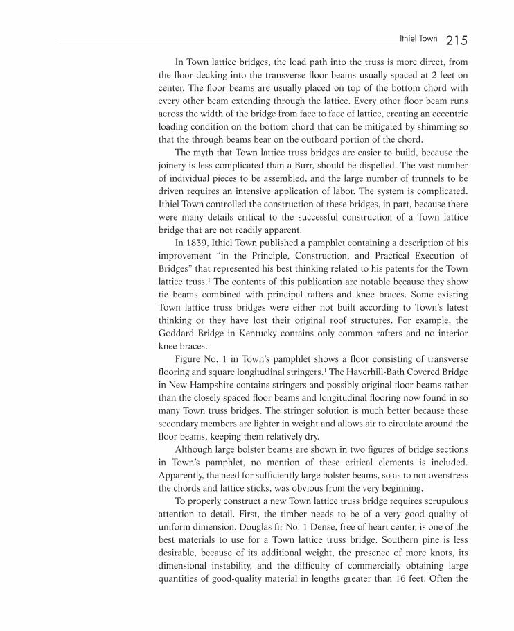
In Town lattice bridges, the load path into the truss is more direct, from the fl oor decking into the transverse fl oor beams usually spaced at 2 feet on center. The fl oor beams are usually placed on top of the bottom chord with every other beam extending through the lattice. Every other fl oor beam runs across the width of the bridge from face to face of lattice, creating an eccentric loading condition on the bottom chord that can be mitigated by shimming so that the through beams bear on the outboard portion of the chord.
The myth that Town lattice truss bridges are easier to build, because the joinery is less complicated than a Burr, should be dispelled. The vast number of individual pieces to be assembled, and the large number of trunnels to be driven requires an intensive application of labor. The system is complicated. Ithiel Town controlled the construction of these bridges, in part, because there were many details critical to the successful construction of a Town lattice bridge that are not readily apparent.
In 1839, Ithiel Town published a pamphlet containing a description of his improvement “ in the Principle, Construction, and Practical Execution of Bridges ” that represented his best thinking related to his patents for the Town lattice truss. 1 The contents of this publication are notable because they show tie beams combined with principal rafters and knee braces. Some existing Town lattice truss bridges were either not built according to Town ’ s latest thinking or they have lost their original roof structures. For example, the Goddard Bridge in Kentucky contains only common rafters and no interior knee braces.
Figure No. 1 in Town ’ s pamphlet shows a fl oor consisting of transverse fl ooring and square longitudinal stringers. 1 The Haverhill - Bath Covered Bridge in New Hampshire contains stringers and possibly original fl oor beams rather than the closely spaced fl oor beams and longitudinal fl ooring now found in so many Town truss bridges. The stringer solution is much better because these secondary members are lighter in weight and allows air to circulate around the fl oor beams, keeping them relatively dry.
Although large bolster beams are shown in two fi gures of bridge sections in Town ’ s pamphlet, no mention of these critical elements is included. Apparently, the need for suffi ciently large bolster beams, so as to not overstress the chords and lattice sticks, was obvious from the very beginning.
To properly construct a new Town lattice truss bridge requires scrupulous attention to detail. First, the timber needs to be of a very good quality of uniform dimension. Douglas fi r No. 1 Dense, free of heart center, is one of the best materials to use for a Town lattice truss bridge. Southern pine is less desirable, because of its additional weight, the presence of more knots, its dimensional instability, and the diffi culty of commercially obtaining large quantities of good - quality material in lengths greater than 16 feet. Often the
Ithiel Town 215
c15.indd 215c15.indd 215 12/18/08 10:21:19 PM12/18/08 10:21:19 PM

216 The Timber Trusses of Burr, Town, and Haupt
design of a Town lattice requires lengths of bottom chord material in the 32 to 36 foot range.
Arnold Graton of Ashland, New Hampshire, has built more Town lattice timber truss bridges than anyone else now living. Working with his father, Milton Graton, for 37 years, he learned the particulars of the Town lattice truss as if he had sat at the knee of Ithiel Town himself.
FIGURE 15-5 Arnold Graton (left) with his son “JR” Graton in Thomaston, Georgia.
The Town lattice requires a wide bearing surface for the truss so that bottom chord, lattice, and connections are not overstressed. The general rule of thumb is that the truss should extend beyond the center of the bearing equal to the depth (height) of the truss. Town lattice trusses usually terminate at a built - up end post. If the end of the truss is close to the bearing point, the endpost may greatly affect the forces in the lattice braces and counter braces. Bearing blocks, bed timbers and bolster beams can be confi gured to enhance the capacity of a Town lattice truss. The Auchumpkee Covered Bridge in Thomaston, Georgia, was originally built with very heavy double - cantilevered bolster beams that tapered down in depth from their supports. These were reused in Arnold Graton ’ s 1996 reconstruction of the bridge that had been destroyed in a fl ood. The tapered confi guration is not only visually pleasing, it provides a gentle transition between the main span and the supports.
A Town lattice truss will be substantially stronger if the chord sticks are as long as possible. By scattering the end joints in the bottom chord in a rational manner, there is less chance that a joint will fall precisely at midspan or at the most critical point in the bottom chord. A more subtle consideration is load
c15.indd 216c15.indd 216 12/18/08 10:21:19 PM12/18/08 10:21:19 PM

sharing between individual leaves. The trunnels not only connect chords and lattice together, they also allow for load sharing within the individual chord sticks to provide continuity through joint locations. Drawings for new or existing Town lattice trusses should show the distribution of joints in all chords with the length of the chord sticks noted. Replacement chord sticks installed in a bridge should respect the original joint locations.
During the fi rst Covered Bridge Conference held in Burlington, Vermont, in February 2003, we observed and briefl y reviewed the analysis of several covered bridges as performed by universities for government agencies, and by traditional highway bridge engineers as consultants. In the fi rst case, the effort is academic, resulting in an educational tool used to transfer knowledge to the design community. In the second case, there are serious gaps in the understanding of how these timber structures perform by some members of the highway bridge design community. Some engineers demonstrate their lack of knowledge of timber design when they talk of “ shear planes ” in the design of trunnels. The capacity of trunnels used as the primary connector in Town lattice trusses is governed by the bearing in the trunnel perpendicular to grain. Timber elements do not fail in shear across the grain. When a load is applied perpendicular to the longitudinal axis of a timber pin, it may fail in bearing perpendicular to grain, in horizontal shear, or bending; but not in shear through its cross - section. Since bearing in the pin controls the design, increased capacity in Town lattice connections can be achieved by increasing the diameter of the pins or by
FIGURE 15-6 The original double-cantilevered bolster beams were reused at the Auchumpkee Creek Covered Bridge.
Ithiel Town 217
c15.indd 217c15.indd 217 12/18/08 10:21:21 PM12/18/08 10:21:21 PM
218 The Timber Trusses of Burr, Town, and Haupt
selecting trunnel material with a high allowable design value in bearing perpendicular to grain such as live oak, locust, or mesquite.
Many highway, county, and consulting engineers, considering ways to increase the capacity of Town lattice trusses, have added steel splice plates at bottom chord joints. Connections such as these may be effective if the drilling is very accurate, the holes not more than 1/16th of an inch larger than the bolt diameter, the connection consists of two plates with the connection in double shear, and the connections are prestressed by jacking some camber into the bridge prior to drilling the holes. In actual practice, none of these conditions are met.
The iron and steel dogs, found in Town lattice railroad bridges, to fasten chord sticks together, work much better because they were installed with great precision during original construction. In some cases they are adjustable and can be tightened.
RETROFITTED ARCHES
In this chapter we must discuss the use of the retrofi tted nail laminated timber arch as stiffening and strengthening devise installed in many covered bridges of the multiple kingpost design. Obviously, these bridges should not be categorized as Burr arch - trusses for they do not follow the Burr patent.
The considerable structural advantages of retrofi tted two - hinged nail or bolted laminated arches offer a strong case for not restoring a bridge to the earlier time period that does not include the arches. It can easily be demonstrated that retrofi tted nail laminated two - hinge arches do not share load - carrying capacity equally with the truss system. If properly built and maintained, the nail or bolt laminated two - hinged arch adds considerable stiffness to the bridge structure.
The capacity of the arches depends on the supports being nonyielding and the arches being held in line to avoid buckling out of plane. For the arches to work, the arch ends must bear against a thrust block capable of resisting all horizontal and vertical forces without movement. This is one “ Achilles ’ heel ” of retrofi tted nail laminated stiffening arches. The second possible defect in nailed or stitch bolted arches is the lack of suffi cient fastening to resist shear forces between individual laminations caused by bending moments induced by unbalanced loads.
If a bridge retrofi tted with two hinged laminated arches is raised to avoid fl oods or ice in the river, then the stone abutments and piers will have to be modifi ed or rebuilt to accommodate the horizontal thrust of the arches.
c15.indd 218c15.indd 218 12/18/08 10:21:21 PM12/18/08 10:21:21 PM

The boundary (support) conditions for both the arches and the trusses are very important to the evaluation and condition assessment of the bridge. The ability of the pier and abutments to resist the horizontal thrust of the arches without movement is critical.
The reconfi guration of bed timbers, bearing blocks and bolster beams at supports is a powerful tool in strengthening an historic covered bridge because the truss superstructure is not affected. These elements are among the fi rst to deteriorate because of their proximity to stone, earth, and water. Because of this, these pieces are rarely original to the period of construction. Often, the current timbers are creosote treated replacements. Enlarging bed timbers can reduce the span of a bridge, greatly reducing member forces.
HERMAN HAUPT
From an engineering standpoint, it could be argued that the best form for a new covered timber bridge would be a double Town lattice with a stiffening arch. For any refi nement of the Town lattice truss, the designer should simply look to General Herman Haupt ’ s Improved Lattice Truss. General Haupt (1817 – 1905), a noted bridge designer from Pennsylvania, graduated from West Point and became chief of military railroads during the Civil War.
Rigorous mathematical methods of analyzing the forces and stresses in framed structures, such as bridges, were unknown until the 1840s. Civil engineers Squire Whipple and Herman Haupt independently developed mathematical methods of truss design. In 1842, Herman Haupt produced a small pamphlet, “ Hints on Bridge Construction by an Engineer. ” 2
Squire Whipple is credited with developing the scientifi c basis of bridge design in America with his 1847 publication, “ A Work on Bridge Building. ” In 1851, Herman Haupt produced his major work, General Theory of Bridge Construction. 2
THE BUNKER HILL COVERED BRIDGE
In North Carolina, the Bunker Hill Covered Bridge, owned by the Catawba County Historical Society, was built in 1895 in general accordance with General Haupt ’ s 1839 design patent.
The Bunker Hill Bridge is 80 feet, 2 inches long (out - to - out) and 10 feet wide. The fl oor consists of two layers of 2 � 8 and 2 � 10 deck boards supported by 3 � 10 fl oor beams spaced approximately 34 inches on center. The Bunker
The Bunker Hill Covered Bridge 219
c15.indd 219c15.indd 219 12/18/08 10:21:22 PM12/18/08 10:21:22 PM

220 The Timber Trusses of Burr, Town, and Haupt
Hill Covered Bridge is the only remaining example of Herman Haupt ’ s 1839 patent for the Improved Lattice Truss. It is the older of only two remaining historic covered bridges in North Carolina and is on the National Register of Historic Places. It is located approximately one mile east of a former stagecoach stop in Catawba County.
The trusses consist of 3 � 12 posts (vertical web members) and double 2 � 12 braces (diagonal compression web members) in a lattice design where the braces cross two panels. The top chord consists of two 2 � 12s on each side of the braces that contain the posts at the centerline of the truss. The bottom chord consists of four 3 � 12 members. The end post is a 6 � 12. The fi rst brace is a notched 12 � 6 with the second post passing through a rectangular hole in the brace. Connections between members are wood trunnels (pegs), usually three per joint. Two of the four members that form the chords are cut at the same splice locations, resulting in a net cross - sectional area in tension members equal to one - half of the gross cross - sectional area.
In 1987, we provided an accurate analysis of the Haupt truss confi guration of the Bunker Hill Covered Bridge. The axial forces in individual webs and chords were obtained, as well as local bending moments in continuous members.
We performed an analysis on an AT & T PC 6300 computer using a plane frame analysis program to model the truss. The computer model contained of 55 joints and 94 members.
The computer model included “ link ” connections at interior web intersections to simulate the continuity of lapped member connections where there is shear transfer between members, but each of the intersecting members maintains its continuity through the joint. The links are one - thousandth of a foot in length. We used for the link connections, the section properties equivalent to one, two - inch diameter trunnel.
The chords were modeled as continuous members, as were individual web “ sticks. ” This is more accurate than the usual truss design assumption that all members are pinned at their intersections, including chord members. The supports were modeled as idealized hinge or roller supports.
It is important to note that the truss model analyzed assumed a theoretical truss containing no deterioration or damage. Defects in individual timber members, as well as slippage in connections and shrinkage in connections or members, were not accounted for in the computer model.
Design Loads Although the bridge is located in Conner Park in Claremont, North Carolina, and is used for pedestrian traffi c only, we analyzed the trusses for both pedestrian traffi c and uniform lane loading equivalent to AASHTO H15 - 44.
c15.indd 220c15.indd 220 12/18/08 10:21:22 PM12/18/08 10:21:22 PM

The pedestrian traffi c load combination consists of 100 psf fl oor live load in accordance with the 1978 edition of the North Carolina State Building Code for Catawba County.
Timber Member Evaluation The capacities of the members, and of the spliced connections were evaluated using the forces obtained from the computer program. We did not visually identify the species of wood used in the constructions of this bridge, other than to tentatively identify it as dense red oak for lattice sticks and southern pine for chords. We assumed conservative design values of E � 1500 ksi, F b � 1400 psi, F t � 1100 psi, and F c � 1700 psi (parallel) for this evaluation.
The computer analysis indicated that the critical areas of the truss were at the splices in the bottom chord and at the second brace. We computed tension forces for net cross - sectional areas not containing a splice as well as sections assumed to contain two splice joints in the critical bottom chord.
Analysis The preliminary structural analysis did not include a detailed analysis of the connections. The truss and fl oor beams were adequately sized to support uniform loads imposed by pedestrian traffi c as well as an H15 vehicular loading for a one - lane bridge. Defl ection under these loads was computed to be less than one - half of an inch across the full span.
The support of the bridge by the abutments was close to the second post location. This support condition reduced the overall stresses in the truss by reducing the span but overstressed the second diagonal somewhat under the design loads.
Condition Survey In 1987, we pronounced the Bunker Hill Covered Bridge to be in good condition. The tin roof did not leak. Roof rafters, truss members, fl oor beams, fl oor decking, and lateral cross - bracing were generally in good to excellent condition. Some posts and braces contained unusual holes and notches, which may have been misdrilled holes or notches made by vandals. Although the concrete and stone abutments that were repaired or rebuilt by the Department of Transportation were not an authentic restoration, the structural condition of the abutments appeared good.
Although the abutments are well constructed, backfi ll on the sides of the abutments and at the ends of the bridge constituted a decay problem to the wood in close contact with soil or concrete. A concrete swale use to divert runoff around the sides of the abutments was located too close to the siding. The ends
The Bunker Hill Covered Bridge 221
c15.indd 221c15.indd 221 12/18/08 10:21:22 PM12/18/08 10:21:22 PM

222 The Timber Trusses of Burr, Town, and Haupt
of the siding boards were decayed in several areas. The powder post beetle or some similar boring insect had attacked the truss members.
At the time, we made fi ve recommendations:
1. We recommend maintaining the existing tin roof rather than reroofi ng with wood shingles. Tin is economical, noncombustible, light in weight, and sheds snow. For these reasons, it remains the roofi ng material of choice for many New England covered bridges.
2. The wood of the bridge at the abutments should be “ insulated ” from direct contact with earth or concrete. The concrete swale should be rebuilt so that it is not in contact with the superstructure or siding. The ends of the bridge fl oor and chord members should be protected from direct contact with earth.
3. Consideration should be given to installing an automatic fi re - protection system.
4. The bridge should be swept or blown clean with compressed air on a periodic basis to remove debris that has accumulated on and around the bottom chord.
5. Consideration should be given to nominating the Bunker Hill Covered Bridge for inclusion in the American Society of Civil Engineer ’ s National Historic Landmark Program.
We concluded that the Bunker Hill Covered Bridge, is a very signifi cant example of nineteenth - century bridge technology, is in excellent condition, and is well maintained.
Herman Haupt was involved in so many emerging technologies for so many years, his early timber bridge design work is almost forgotten. His autobiographical Reminiscences of General Herman Haupt overshadows much of his previous work and many of his later accomplishments.
Haupt ’ s improved lattice truss bridge was a response to Ithiel Town ’ s 1820 and 1835 patents for the plank lattice timber truss. Haupt used the analytical methods he developed in the 1840s to design a more effi cient lattice truss, which consisted of web members positioned only at locations that required support. Redundant members were removed, resulting in the improved lattice truss as described in his book General Theory of Bridge Construction published in 1851. 2
The Bunker Hill Covered Bridge is the only remaining example of the bridge truss design by Herman Haupt in 1840 and illustrated in his 1851 book General Theory of Bridge Construction , Fig 90, Page 153. 2
c15.indd 222c15.indd 222 12/18/08 10:21:23 PM12/18/08 10:21:23 PM

General Haupt was keenly aware that his knowledge and ability as a civil engineer was vital in ensuring the health, safety, and welfare of the general public:
“ With even greater simplicity and economy than the ordinary lattice, it appears to be entirely free from its defects; and possessing many of the essential requi-sites of a good bridge, with a capability of extension to spans of considerable length, it seems to be unusually well adapted to the wants of a community with whom economy is an object. ” 2
In the Bunker Hill Covered Bridge, with the skin removed, we see the handiwork of Herman Haupt.
FIGURE 15-7 An illustration of the Haupt Truss is on the fi rst page of the chapter titled “Improved Lattice” from General Theory of Bridge Construction (Ref. 2).
FIGURE 15-8 The Bunker Hill Covered Bridge with repairs almost completed. (See color insert.)
The Bunker Hill Covered Bridge 223
c15.indd 223c15.indd 223 12/18/08 10:21:23 PM12/18/08 10:21:23 PM

224 The Timber Trusses of Burr, Town, and Haupt
This opportunity came when a windstorm uprooted a tree next to the bridge, smashing the south portal. The damage revealed considerable damage where the ends of the bridge had been encapsulated by concrete when the bridge was previously repaired. Having completed a recent evaluation, Sidney Halma gave us the call to assist with the repairs. With Mr. Halma pleading poverty on behalf of the Catawba County Historical Society, we were limited in what we could provide within our negotiated fee. As a result, we decided that we would produce a minimal set of drawings and invite two or more bridgewrights or qualifi ed timber framers to the site to observe the damage for the purpose of determining the scope of work. To limit my time traveling, and to have the bidders agree on scope, I decided to invite Arnold M. Graton and Jan Lewandoski to visit the site at the same time. Fortunately, they both fl ew from Manchester, New Hampshire to Douglas Airport at Charlotte, North Carolina, aboard the same plane, where I met them, transporting them by automobile to the bridge site. After the three of us spent three to four hours observing conditions, we agreed on a scope of work. Arnold Graton was the successful bidder, and soon he went to work.
During the 1987 rehabilitation, Arnold Graton, removed the side boarding and roofi ng from the bridge in order to gain access to chord members that required repair.
FIGURE 15-9 Deterioration was apparent at all four corners of the bridge.
Deteriorated chord members that were replaced in kind consisted of bottom chord members at the four bearing corners of the bridge. Arnold Graton
c15.indd 224c15.indd 224 12/18/08 10:21:25 PM12/18/08 10:21:25 PM
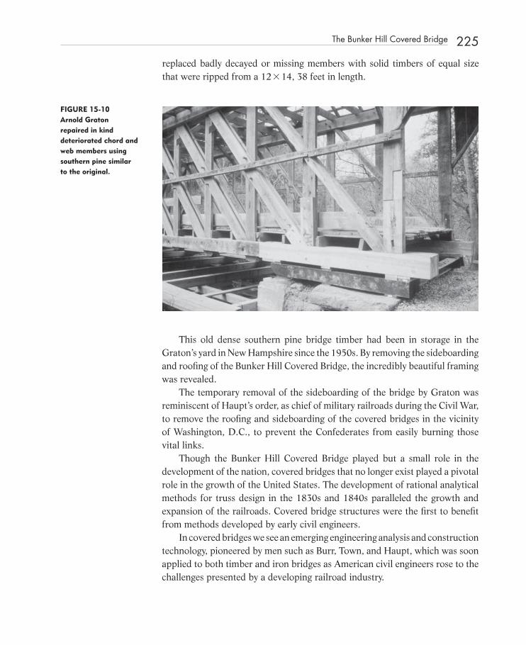
replaced badly decayed or missing members with solid timbers of equal size that were ripped from a 12 � 14, 38 feet in length.
FIGURE 15-10 Arnold Graton repaired in kind deteriorated chord and web members using southern pine similar to the original.
This old dense southern pine bridge timber had been in storage in the Graton ’ s yard in New Hampshire since the 1950s. By removing the sideboarding and roofi ng of the Bunker Hill Covered Bridge, the incredibly beautiful framing was revealed.
The temporary removal of the sideboarding of the bridge by Graton was reminiscent of Haupt ’ s order, as chief of military railroads during the Civil War, to remove the roofi ng and sideboarding of the covered bridges in the vicinity of Washington, D.C., to prevent the Confederates from easily burning those vital links.
Though the Bunker Hill Covered Bridge played but a small role in the development of the nation, covered bridges that no longer exist played a pivotal role in the growth of the United States. The development of rational analytical methods for truss design in the 1830s and 1840s paralleled the growth and expansion of the railroads. Covered bridge structures were the fi rst to benefi t from methods developed by early civil engineers.
In covered bridges we see an emerging engineering analysis and construction technology, pioneered by men such as Burr, Town, and Haupt, which was soon applied to both timber and iron bridges as American civil engineers rose to the challenges presented by a developing railroad industry.
The Bunker Hill Covered Bridge 225
c15.indd 225c15.indd 225 12/18/08 10:21:26 PM12/18/08 10:21:26 PM

226 The Timber Trusses of Burr, Town, and Haupt
REFERENCE S
1. Town, Ithiel. A Description of Ithiel Town ’ s Improvement in the Construc-tion of Wood and Iron Bridges: Intended as a General System of Bridge - Building for Rivers, Creeks, and Harbours of Whatever Kind of Bottoms; and for any Practicable Width of Span or Opening, in Every Part of the County. New Haven: S. Converse, 1821.
2. Haupt, H. General Theory of Bridge Construction, New York: Appleton and Co., 1851.
c15.indd 226c15.indd 226 12/18/08 10:21:27 PM12/18/08 10:21:27 PM

227
C H A P T E R1 6 The Cornish - Windsor Covered Bridge
T T he conservation of the Cornish - Windsor Bridge was a compromise among rehabilitation - in - kind proponents, authentic restoration advocates, and
Vermont and New Hampshire governmental offi cials. This compromise replaced overstressed wood with glued laminated timber, a modern - day forest product. The fi ne - grained virgin eastern white spruce timber that was used originally is no longer grown. The use of glued laminated timber preserved the appearance of the bridge, preserved the Town lattice structural system, minimized the use of steel, and met modern highway standards.
It has been estimated that at one time, the United States contained at least 10,000 covered timber bridges 1 . In 1980, six states contained 78 percent of our remaining 893 covered bridges 2 . Certainly, the remaining covered bridges enhance the quality of life for artists, tourists, and preservationists who seek out these romantic reminders of past technology.
What kind of preservation philosophy is needed in order for us to conserve our remaining covered bridges? Perhaps the Cornish - Windsor case study will provide insight into a conservation process of engineering analysis and preser-vation philosophy that led to the compromise solution that was completed in November 1989.
The 460 - foot - long Cornish - Windsor Covered Bridge, which links Cornish, New Hampshire, with Windsor, Vermont, is a special covered bridge. The bridge,
c16.indd 227c16.indd 227 12/18/08 10:21:56 PM12/18/08 10:21:56 PM
Structural Investigation of Historic Buildings: A Case Study Guide to Preservation Technology for Buildings,Bridges, Towers, and Mills. David. C. Fischetti © 2009 John Wiley & Sons, Inc.
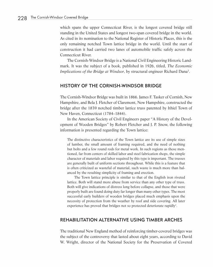
228 The Cornish-Windsor Covered Bridge
which spans the upper Connecticut River, is the longest covered bridge still standing in the United States and longest two - span covered bridge in the world. As cited in its nomination to the National Register of Historic Places, this is the only remaining notched Town lattice bridge in the world. Until the start of construction it had carried two lanes of automobile traffi c safely across the Connecticut River.
The Cornish - Windsor Bridge is a National Civil Engineering Historic Land-mark. It was the subject of a book, published in 1926, titled, The Economic Implications of the Bridge at Windsor , by structural engineer Richard Dana 3 .
HISTORY OF THE CORNISH - WINDSOR BRIDGE
The Cornish - Windsor Bridge was built in 1866. James F. Tasker of Cornish, New Hampshire, and Bela J. Fletcher of Claremont, New Hampshire, constructed the bridge after the 1839 notched timber lattice truss patented by Ithiel Town of New Haven, Connecticut (1784 – 1844).
In the American Society of Civil Engineers paper “ A History of the Devel-opment of Wooden Bridges ” by Robert Fletcher and J. P. Snow, the following information is presented regarding the Town lattice:
The distinctive characteristics of the Town lattice are its use of simple sizes of lumber, the small amount of framing required, and the need of nothing but bolts and a few round rods for metal work. In such regions as those men-tioned, far from centers of skilled labor and steel fabrication shops, the simple character of materials and labor required by this type is important. The trusses are generally built of uniform sections throughout. While this is a feature that is often criticized as wasteful of material, such waste is much more than bal-anced by the resulting simplicity of framing and erection.
The Town lattice principle is similar to that of the English iron riveted lattice. Both will stand more abuse from service than any other type of truss. Both will give indications of distress long before collapse, and those that were properly built are found doing duty far longer than many other types. The most successful early builders of wooden bridges placed much emphasis upon the necessity of protection from the weather by roof and side covering. All later experience has proved that bridges not so protected deteriorate rapidly 1 .
REHABILITATION ALTERNATIVE USING TIMBER ARCHES
The traditional New England method of reinforcing timber - covered bridges was the subject of the controversy that lasted about eight years, according to David W. Wright, director of the National Society for the Preservation of Covered
c16.indd 228c16.indd 228 12/18/08 10:21:57 PM12/18/08 10:21:57 PM

Bridges. The laminated timber arch retrofi t proposed by the Committee for the Authentic Restoration of the Cornish - Windsor Bridge required traditional meth-ods and materials as practiced by Milton S. Graton, craftsman, of Ashland, New Hampshire. Mr. Graton ’ s proposed timber arch solution had a long history.
In a letter to Mr. J. W. Storrs, Consulting Engineer, dated August 1908, J. P. Snow, bridge engineer of the Boston & Maine Railroad, recommended arches for the Cornish - Windsor Bridge. In another letter to Mr. Storrs dated September 15, 1908, Snow stated the following:
. . . regarding Windsor Bridge: — An arch of 20 ’ rise could be used and the fi gures would give a section of 9 � 42 or 10 � 38. . . .
The foot of the arches would need to be very strongly secured to the masonry and timbers would need to be framed between the arches to prevent ice catching on the lower one and to make both of them act together. I think it can be absolutely safe. 4
J. P. Snow co - authored paper No. 1864 (Proceeding, ASCE, November, 1932, Vol. LVIII, pp. 1455 – 1498) of the American Society of Civil Engineers, “ A History of the Development of Wooden Bridges, ” which discussed the con-struction of supplemental arches in timber bridges:
Combinations of arch and truss have been disproved by school men because of the impossibility of determining the theoretical distribution of stress between the truss and the arch; but if there is strength enough in both, and they are properly yoked together, the safe elasticity of the wood and the connections will take care of the distribution. The Town lattice is the best of the various types of wooden trusses to serve as an arch stiffener because its web mem-bers serve either as counters or main braces. The value of arches framed with trusses, if heeled against the masonry, has been amply demonstrated by other types of trusses, some of which have stood for a century. 1
In 1984, Mr. Graton proposed the following as detailed in Plans for the Authentic Restoration of the Cornish - Windsor Covered Bridge . The bridge would be retrofi tted with four radial arches, built up with 2 � 14 ’ s of dense select structural untreated Douglas fi r, mechanically laminated with stitch bolts and spikes. The location of the reinforcing arches at the outside of the trusses of the Cornish - Windsor Bridge would maintain the interior width of the bridge at its original two lanes. Concrete thrust block supports would have to be built into the tops of the two abutments and the central pier in order to create suf-fi cient bearing area. Raising the bridge would be necessary in order to provide the additional clearance needed to place the arches above damaging winter ice. Additional longitudinal fl oor beams and transverse needle beams would also be
Rehabilitation Alternative Using Timber Arches 229
c16.indd 229c16.indd 229 12/18/08 10:21:57 PM12/18/08 10:21:57 PM

230 The Cornish-Windsor Covered Bridge
required to increase the structural capacity of the bridge to HS15 - 44 (the des-ignation for a standard highway design and the minimum live load for high-ways which carry, or may carry, heavy truck traffi c). Load sharing between the new radial rib arches and the trusses would be attained by adjusting threaded hangers or suspender rods, which connected the two elements. 5
Objections to Mr. Graton ’ s arch solution were based on preservation phi-losophy, as well as other issues. Because the arches were to be 20 feet deep, they would spring from a point 4 feet below the bottom of the bridge. The visual impact of the partially exposed curved arches was objectionable to many peo-ple, particularly the Vermont Agency of Transportation, the Vermont Division of Preservation, and the Town of Windsor. In addition, with the arches placed to the outside of the trusses, the bridge cross - section and end appearance would have to change. Probably the greatest objection was the necessity of raising the bridge 4 feet above its original location so that the arches would avoid the win-ter ice that forms in the upper Connecticut River. The bridge raising would change the historic relationship of the bridge to grade at both ends. The street in Windsor and the highway in Cornish would have to be elevated, along with several residential structures. The arch supports would also have extended, beyond the protecting envelope of the bridge, to bear against stone masonry and a concrete thrust block. This critical connection would have been subject to wet-ting by driving rain, high water, and moisture derived from contact with the stone and concrete, as well as ice damage. Protection of the spring point of the arch was a major concern of the opponents of the timber arch retrofi t.
REHABILITATION ALTERNATIVE USING REPLACEMENT - IN - KIND
The solution preferred by the transportation departments and preservation offi ces of both New Hampshire and Vermont was a replacement - in - kind retrofi t that would substitute larger, stronger timbers for existing fabric. The replacement - in - kind solution was shown through analysis not to be feasible for two reasons. First, solid timbers of suffi cient strength were not available. That is, to maintain a cross - section similar to the original chords, new timbers would require design values in tension far exceeding those published for the grades and species of timbers available. Second, the presence of butt joists and shear blocks, which would be required in any replacement chord confi guration of the truss, would reduce the net section in tension. The original chords consisted of four members connected together in such a way that many of the end splices in the 32 - foot - long pieces occurred in areas of high stress.
c16.indd 230c16.indd 230 12/18/08 10:21:58 PM12/18/08 10:21:58 PM

REHABILITATION ALTERNATIVE USING GLUED LAMINATED TIMBER REPLACEMENT CHORDS
In January 1988, I proposed a solution requiring replacement of the original chords with glued laminated timber members in very long lengths, to bridge areas of high stress. Although it was presented with reservations, this solution was immediately accepted by the two departments of transportation. The glued laminated timber replacement chord solution provided the Cornish - Windsor Bridge with an HS15 - 44 capacity without the addition of retrofi tted laminated timber arches. This alternative required the installation of architectural grade, prefabricated, structural glued laminated timber chords and fl oor beams in areas of high tensile stress in the bridge. 6
Structural glued laminated timber, commonly referred to as glulam, was introduced into the United States in 1936 from Germany. In glued laminated timber products, higher design values are obtained by providing clear, dense laminations in areas of high stress. Strength - reducing defects such as large knots are removed. Natural growth characteristics such knots, wane, and checks normally found in all timber materials are considered to be “ defects ” because of their strength - reducing capabilities. 7 In the production of structural glued laminated timber, laminations are glued together with waterproof glue. The surface appearance of structural glued laminated timber does not have to be the slick - planed fi nish often seen in architectural applications. A cross - sanded fi nish approximating a rough sawn appearance can be furnished. 7
For the Cornish - Windsor Bridge, the use of prefabricated glued laminated timber offered fi ve advantages:
1. Because glued laminated timber consists of a number of pieces of laminate glued together, it can be fabricated in longer lengths than solid materials.
2. It can usually be fabricated and shipped within 8 to 10 weeks. This period is less than the total time required for ordering, cutting, and drying large solid timber materials.
3. The moisture content of structural glued laminated material is rigidly controlled. Constant moisture content throughout the cross section of 15 percent or less is provided at the time of shipment. This aspect of glued laminated timber is signifi cant because the shrinkage of truss members after construction can cause additional defl ection as a result of the open-ing of critical joints.
4. Unlike solid timber, structural glued laminated timber is an engineered, stress - rated product of a timber laminating plant. Plant fabrication
Rehabilitation Alternative Using Glued Laminated Timber Replacement Chords 231
c16.indd 231c16.indd 231 12/18/08 10:21:58 PM12/18/08 10:21:58 PM

232 The Cornish-Windsor Covered Bridge
ensures quality control, which is impossible to obtain by fi eld laminating or by using solid materials.
5. Also, glued laminated timber members of southern pine can be pres-sure treated before gluing with complete penetration of the preserva-tive. This is desired to extend the life of members subjected to wetting. Complete penetration of preservative is not obtainable in some species such as Douglas fi r or in the heartwood of most other species.
The advantages of the laminated timber chord replacement design over the timber arch retrofi t immediately became apparent. Modifi cation of the founda-tions of the buttresses and central pier was not required. The cross - section of the bridge would also remain essentially the same. All live and dead loads would be supported by the rehabilitated lattice trusses, thus preserving the use of the original structural technology.
Additional continuity would be built into the bridge by using the longer chord material. This continuity would help to limit future defl ection by elimi-nating splices and shear block connections. Additional transverse and longitu-dinal carrying beams would not be required if laminated timber fl oor beams were substituted for the existing 4 � 16 fl oor beams.
DISADVANTAGES OF THE GLULAM CHORD REPLACEMENT ALTERNATIVE
There are four disadvantages of the laminated timber chord replacement design:
1. The use of structural glued laminated materials integrated into an historic bridge structure may not be acceptable to some historic preservationists.
2. Overall bridge stiffness is not as great as can be achieved with retrofi tted laminated timber arches.
3. Overall bridge safety would depend on relatively few mechanical splices. These critical splices would integrate the new laminated timber chord material with existing bridge fabric. Such work would require a very high level of skill among the timber framers.
4. Long timber pieces are diffi cult to handle, ship, and integrate into the bridge. Precise coordination of fi eld cuts and daps is necessary so that lattice web members fi t as required between the chords.
Early in 1988, the design and construction of the glued laminated timber chord replacement alternative was implemented. In making this decision, the
c16.indd 232c16.indd 232 12/18/08 10:21:58 PM12/18/08 10:21:58 PM

key for us was the confi dence expressed by Jan Lewandowski of Greensboro Bend, Vermont, that he could successfully integrate the glued laminated timber chords into the bridge by scribing and notching. At each lattice to chord con-nection, the members were both notched 1 ¼ inches and pinned. The snug fi t of these joints was critical to the performance of the rehabilitated trusses.
The analysis for the Cornish - Windsor Bridge in 1989 was executed on a personal computer using a STRAAD three - dimensional frame analysis pro-gram. It involved 1,600 members and 2,800 joints for one truss and required approximately 13 hours to run. We modeled joints to allow rotation and conti-nuity at lattice intersections using links.
FIGURE 16-1 The analysis provided forces for 1,600 members.
To obtain realistic support conditions, we modeled springs. It was a frus-trating ordeal because often the 13 - hour process would yield incorrect results. I would start the program at the end of the workday, expecting results the next morning. Too often, summer electrical storms would interrupt the power and I would have to start again.
The results of the analysis were magnifi cent. All of the lattice member and chord forces were produced. We could see the effects of bolster beam supports and accurately determine the optimum locations for chord splices for an array of loading conditions.
A temporary cable - stayed support system was designed to allow construc-tion to proceed while the Connecticut River was fi lled with ice. The design of
Disadvantages of the Glulam Chord Replacement Alternative 233
c16.indd 233c16.indd 233 12/18/08 10:21:59 PM12/18/08 10:21:59 PM

234 The Cornish-Windsor Covered Bridge
the cable stayed temporary support system was an adventure in itself. Origi-nally, Chesterfi eld Associates was planning to shore the bridge from the river. Unfortunately, the Upper Connecticut often freezes during the winter. Moving ice would simply destroy any temporary supports standing in the river. During a meeting with NHDOT engineers and offi cials, Dave Allen, of Chesterfi eld Associates, the contractor, explained that the two - year construction schedule would require work to be phased in such a way to avoid the ice. The plan was to work on the two spans of the bridge independently. While the discussion ensued, I was quietly sketching on the proverbial, “ back of an envelope. ” I quickly sketched the bridge with a two - span cable stayed structure to allow the symmetrical two - span bridge to be rehabilitated in a symmetrical manner. After presenting the sketch and interjecting a few comments into the discus-sion, the advantages of such a system became apparent to all. It was immedi-ately embraced. The cable - stayed system had to be fast tracked. We designed the three 80 - foot towers using 10HP42 steel piles, which were available to the contractor. The steel system consisted of transverse needle beams, two longitu-dinal carrying beams, built - up towers, and an array of 140 ksi Dywidag ® bars for stays. The design was handsketched on notebook paper and faxed to the jobsite on a “ just in time ” schedule so that welders would not be waiting.
FIGURE 16-2 The towers were fabricated in a fi eld on the Cornish, New Hampshire, side of the river.
Two towers were erected on opposite banks, and one on the central pier.
c16.indd 234c16.indd 234 12/18/08 10:21:59 PM12/18/08 10:21:59 PM

Larger concrete dead men with earth anchors were installed to resist the pull of the stays on the end towers. The needle beams provided a perfect sup-port for a rail and rolling hoist.
FIGURE 16-3 The cable stayed system allowed for an orderly rehabilitation of the roof structure. (See color insert.)
FIGURE 16-4 The glued laminated timber chords were as much as 116 feet in length.
Disadvantages of the Glulam Chord Replacement Alternative 235
c16.indd 235c16.indd 235 12/18/08 10:22:00 PM12/18/08 10:22:00 PM

236 The Cornish-Windsor Covered Bridge
This enabled the long glued laminated timber chord replacement members and other materials to be pulled into the bridge.
FIGURE 16-6 The cable stayed system allowed work to proceed through the winter.
The cable - stayed system allowed work to continue through the winter and the repairs to be made in a symmetrical manner that was important for a two - span continuous truss with very high tensile stresses in the top chord over the central pier.
FIGURE 16-5 Glued laminated timber was used for chord replacement material, fl oor beams, and bolster beams.
c16.indd 236c16.indd 236 12/18/08 10:22:03 PM12/18/08 10:22:03 PM
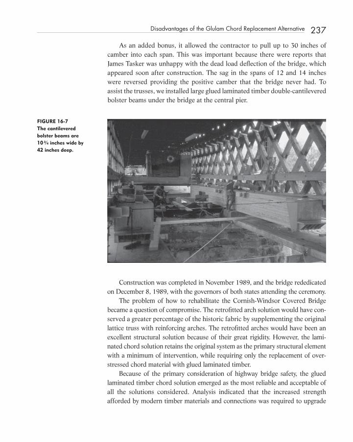
As an added bonus, it allowed the contractor to pull up to 30 inches of camber into each span. This was important because there were reports that James Tasker was unhappy with the dead load defl ection of the bridge, which appeared soon after construction. The sag in the spans of 12 and 14 inches were reversed providing the positive camber that the bridge never had. To assist the trusses, we installed large glued laminated timber double - cantilevered bolster beams under the bridge at the central pier.
FIGURE 16-7 The cantilevered bolster beams are 10 ¾ inches wide by 42 inches deep.
Construction was completed in November 1989, and the bridge rededicated on December 8, 1989, with the governors of both states attending the ceremony .
The problem of how to rehabilitate the Cornish - Windsor Covered Bridge became a question of compromise. The retrofi tted arch solution would have con-served a greater percentage of the historic fabric by supplementing the original lattice truss with reinforcing arches. The retrofi tted arches would have been an excellent structural solution because of their great rigidity. However, the lami-nated chord solution retains the original system as the primary structural element with a minimum of intervention, while requiring only the replacement of over-stressed chord material with glued laminated timber.
Because of the primary consideration of highway bridge safety, the glued laminated timber chord solution emerged as the most reliable and acceptable of all the solutions considered. Analysis indicated that the increased strength afforded by modern timber materials and connections was required to upgrade
Disadvantages of the Glulam Chord Replacement Alternative 237
c16.indd 237c16.indd 237 12/18/08 10:22:04 PM12/18/08 10:22:04 PM

238 The Cornish-Windsor Covered Bridge
FIGURE 16-8 The governors of both New Hampshire and Vermont attended the dedication ceremony. (See color insert.)
FIGURE 16-9 Key to the project was the ability to successfully integrate glulam sticks into the notched Town lattice system.
the Cornish - Windsor Bridge to a level that would allow it to be kept in service as a highway bridge. Conservation of our historic timber bridges can become a real-ity when the solution combines the ultimate goal of highway safety with a sound preservation philosophy. Only through rigorous structural analysis, which recog-nizes the special conditions inherent in historic timber structures, does suffi cient information on which to base sensitive preservation decisions become available.
c16.indd 238c16.indd 238 12/18/08 10:22:05 PM12/18/08 10:22:05 PM

REFERENCES
1. FitzSimons, L. Neal, et al. American Wooden Bridges, ASCE Historical Publication No. 4. New York: American Society of Civil Engineers, 1976.
2. Donovan, Richard T., ed. World Guide to Covered Bridges. Boston: National Society for the Preservation of Covered Bridges, Inc. 1980.
3. Dana, Richard T. The Bridge at Windsor, Vt., and Its Economic Implications. New York: Codex Book Co., Inc., 1926. Copy in Wilbur Collection, University of Vermont Library.
4. Snow, J.P. (Bridge Engineer, Boston and Maine Railroad, Boston), letter to J.W. Storrs (Consulting Engineer, Concord, NH), Aug. 22, 1908, Engineering Society Library, New York, NY
5. Graton, Milton S. and Wright, David W. Plans for the Authentic Restoration of the Cornish - Windsor Covered Bridge. Unpublished report, 1984; revised, 1987.
6. Fischetti, David C. “ Glulam Chord Replacement Alternative, Cornish - Windsor Covered Bridge ” report, Jan. 19, 1988.
7. American Institute of Timber Construction. Timber Construction Manual. 3 rd ed. New York: John Wiley and Sons, 1985.
FIGURE 16-10 Camber remained in the completed bridge for several years.
References 239
c16.indd 239c16.indd 239 12/18/08 10:22:06 PM12/18/08 10:22:06 PM

241
C H A P T E R1 7 A New Covered Bridge for Old Salem
A A unique covered bridge has been built in the United States. The North Carolina Department of Transportation project provided a pedestrian
overpass over Highway 52 at Old Salem, the site of North Carolina ’ s fi rst Moravian community. Moravian settlers arrived in North Carolina from Bethlehem, Pennsylvania, in 1753.
To enhance and blend with the cultural landscape and historic architecture of Old Salem, several types of covered bridge structures were considered. The fi nal choices were the Burr arch - truss and the Town lattice. The Burr arch - truss is a two - hinged arch combined with a multiple kingpost truss. The arch affords great stiffness. The Town lattice has many redundant members, providing a truss with great toughness. Although Theodore Burr ’ s (1771 – 1822) patent of 1817 claimed nothing but the arch, combined with the multiple kingpost truss, it became the most popular covered bridge structural system in the United States.
Of the seven surviving covered bridges in Lehigh and Northampton coun-ties near Bethlehem, Pennsylvania, all are Burr arch - trusses. In 1970, nearly 300 Burr arch - trusses were still standing, with 175 located in Pennsylvania; this was the type of bridge that the Moravians would have constructed for themselves in Salem during the fi rst half of the nineteenth century. For this reason, it was decided that the Burr arch - truss was the logical choice for the
c17.indd 241c17.indd 241 12/18/08 10:23:01 PM12/18/08 10:23:01 PM
Structural Investigation of Historic Buildings: A Case Study Guide to Preservation Technology for Buildings,Bridges, Towers, and Mills. David. C. Fischetti © 2009 John Wiley & Sons, Inc.

242 A New Covered Bridge for Old Salem
covered bridge built at Old Salem. This paper will discuss the development of the design for the Old Salem Bridge and the application of covered bridge technology to both the preservation of historic structures and the construction of modern transportation structures.
THE CONCEPT
Why build a covered bridge at Old Salem? As a tourism destination, Old Salem needed a pedestrian overpass structure to enhance and blend with its cultural landscape and historic architecture. The choice of a covered bridge conforms to the traditional technology of covered bridge building in North America. At the same time, it was important to Old Salem planners, such as John Larson, that the structure not be mistaken for an original artifact. To differentiate, the bridge is clad with transparent panels that give a modern appearance while exposing the traditional interior construction.
FIGURE 17-1 The acrylic panels provided a weathertight sidewall closure. (See color insert.)
The bridge serves as a gateway for vehicular traffi c entering Old Salem as the museum community expands westward.
c17.indd 242c17.indd 242 12/18/08 10:23:02 PM12/18/08 10:23:02 PM

DESCRIPTION
The bridge is a 120 - foot span Burr arch covered bridge that spans business Highway 52 through the city of Winston - Salem, enabling pedestrians to gain access to Old Salem from a visitors parking lot. Pedestrians using this bridge enter Old Salem adjacent to the Museum of Early Southern Decorative Arts.
The bridge is framed with two massive Burr arch - trusses, 15 feet, 10 inches in height with a 5 - foot rise. The chords and arch are built up from several mem-bers with staggered splices to provide continuity. Individual chord members are 5 inches square in cross - section. The braces are rectangular in section. The posts are large, cut to shape timbers, which contain offsets at brace - bearing points.
FIGURE 17-2 The brace to chord connections had to be made tight in the fi eld.
The roof deck is 2 � 6 (1 ½ by 5 ¼ ) tongue and groove decking. The fl oor deck is 3 � 6 (1 ½ by 5 ¼ ) double tongue and groove decking. All of the timber materials are various species of southern pine. The bridge is protected by a standing seam copper roof and transparent acrylic wall panels.
The arches spring from two cast - in - place concrete, stone - faced abutments. To conform to the Americans with Disabilities Act, the 5 - foot rise was
confi gured into a system of ramps and platforms.
Description 243
c17.indd 243c17.indd 243 12/18/08 10:23:03 PM12/18/08 10:23:03 PM

244 A New Covered Bridge for Old Salem
FIGURE 17-3 The bridge is protected by a standing seam copper roof.
FIGURE 17-4 The arches spring from stone-clad concrete abutments.
There is no historical precedent for a covered bridge at this location or in the vicinity of Old Salem. Certainly, however, North Carolina had many cov-ered bridges, which spanned nearby rivers such as the Deep, Catawba, Haw, Dan and the Yadkin. 1
c17.indd 244c17.indd 244 12/18/08 10:23:04 PM12/18/08 10:23:04 PM

HISTORY
In 1751, the land now occupied by the city of Winston - Salem in North Carolina was a wilderness crossed by the hunting trails of the Cherokee, Creek, and Catawba Indian tribes. In London, leaders of the Moravian Church were con-sidering an offer of John Carteret, the Earl of Granville, to sell them a large tract of land from his holdings in the North American colony. The Moravians, the spiritual descendants of the Czech priest Jan Hus who was martyred in 1415, had established in 1741, the town of Bethlehem, Pennsylvania, as their chief center in North America. It is from Bethlehem that Moravian explorers set out in August 1752 to search for suitable land. 2
A small group of fi ve men left Pennsylvania traveling down the coast past the Chesapeake Bay to Edenton, North Carolina. Their leader was Bishop August Gottlieb Spangenberg, whose task it was to search for the 100,000 acres of land for the church to purchase from the Earl of Granville. Accompa-nied by the Earl of Granville ’ s chief surveyor and three local inhabitants, they traveled westward. 2
After a wrong turn that led them into the North Carolina mountains, the group found the tract of land they were searching for. They had surveyed several plots that proved to be unsuitable prior to locating a large tract of land, which they named Wachovia. 2 In the following year, 1753, a group of Single Brethren
FIGURE 17-5 The 5-foot rise had to be confi gured into a series of ramps and landings to conform with ADA.
History 245
c17.indd 245c17.indd 245 12/18/08 10:23:07 PM12/18/08 10:23:07 PM

246 A New Covered Bridge for Old Salem
(unmarried Moravian men) journeyed from Pennsylvania, down the Shenandoah River Valley, and into North Carolina to establish a new settlement. 2 In 1755, the fi rst married couples arrived to take up residence in the temporary town of Bethabara. The permanent settlement of Salem was established in 1766.
For many decades, overland travel between the two Moravian communities was common. This historical link between Pennsylvania and North Carolina is important in the justifi cation of the type of truss system selected for the new Salem Bridge.
PROJECT JUSTIFICATION
The following time line is provided to show that a Burr arch - truss is the most logical choice for this particular span.
1753 The fi rst Moravian settlers arrive from Bethlehem, Pennsylvania. They establish Bethabara as a temporary community.
1771 Theodore Burr, a Harrisburg, Pennsylvania engineer and contrac-tor is born in Connecticut.
1776 The residents of Bethabara move to Salem.
1784 Ithiel Town, a New Haven, Connecticut, architect, engineer, and bridge promoter is born.
1804 Theodore Burr builds a 400 - foot span bridge across the Hudson River at Waterford, New York.
1817 Theodore Burr ’ s patent of 1817 claimed nothing but the arch com-bined with the multiple kingpost truss. This became the most pop-ular covered bridge structural system.
1820 Ithiel Town ’ s plank - lattice design patent.
1822 Financial failure and death of Theodore Burr.
1835 Ithiel Town (1784 – 1884) secured a patent for a lattice bridge with double webs and secondary chords.
1835 The Humpback bridge is built near Covington, Virginia. The 120 - foot - long multiple kingpost bridge has an 8 - foot rise.
1842 The pamphlet “ Hints on Bridge Construction by an Engineer ” is published by Herman Haupt of Pennsylvania.
1844 Ithiel Town dies.
1894 Bunker Hill Covered Bridge is built in Claremont, North Carolina, after Herman Haupt ’ s improved lattice.
c17.indd 246c17.indd 246 12/18/08 10:23:08 PM12/18/08 10:23:08 PM

1970 The oldest covered bridge in the United States, built in 1812, is a Burr located near Lewisburg, Pennsylvania.
1971 Nearly 300 Burr arch - trusses are still standing, with 175 located in Pennsylvania, more than in any other state.
1980 Of 893 historic covered bridges remaining in the United States, 231 are in Pennsylvania and 6 in North Carolina.
1989 Surviving Covered Bridges in Northampton County near Bethlehem, Pennsylvania include:
Name SpanType Date Built
Solts Mill/Kreidersville 115 ft. Burr arch 1840
1989 Surviving covered bridges in Lehigh County near Bethlehem, Penn-sylvania include:
Name SpanType Date Built
Bogert 187 ft. Burr - arch 1841
Wehr 236 ft. Burr - arch 1841
Manassas Guth 127 ft. Burr arch 1858
Rex 136 ft. Burr - arch 1858
Geiger 130 ft. Burr - arch 1858
Schlicher 127 ft. Burr arch 1882
The Burr arch - truss was the logical choice for a covered bridge in Old Salem. This is the type of bridge that Moravian settlers would have built during the fi rst half of the nineteenth century as their community matured. During this period, many Burr arch - trussed bridges were built in Northampton and Lehigh Counties in Pennsylvania near the Moravian settlement of Bethlehem. In 1970, nearly 300 Burr arch - trusses were still standing, with 175 located in Pennsylvania. Of the seven surviving covered bridges in Lehigh and Northampton counties near Bethlehem, Pennsylvania, all are Burr arch - trusses 3 . Although a Town lat-tice bridge was proposed to be constructed on the plank road near Old Salem, this type of bridge was not desirable as a pedestrian bridge because it does not provide suffi cient open space between chords to produce an open appearance. The Town lattice is distinctive in its use of simple sizes of lumber, and the small amount of framing. The resulting simplicity of framing requires less skilled labor but produces a closed tunnellike structure that must overshoot its sup-ports in order to distribute its end reactions. The Burr arch - truss requires great
Project Justifi cation 247
c17.indd 247c17.indd 247 12/18/08 10:23:09 PM12/18/08 10:23:09 PM

248 A New Covered Bridge for Old Salem
skill in timber framing, like the large Dutch barns found in many German communities. In chapter 15 , we dispel the common belief that the Town lattice is simpler to build than a Burr arch - truss.
Louis Wernwag (1770 – 1843), who was born in Germany, and Timothy Palmer (1751 – 1821) of Newburyport, Massachusetts, built many great timber bridges. Their bridges varied in design and construction, each being designed for a specifi c span, using a one - of - a - kind trussed arch. Because of their com-plexity, a pedestrian bridge built after the designs of Wernwag and Palmer was judged impractical for this project. For these reasons, it was decided that the Burr arch - truss was the logical choice for a covered bridge at Old Salem.
RECYCLED TIMBER
Originally, the drawings indicated that the large posts were to be recycled mate-rial. The intent was to obtain these members with reasonable moisture content so that shrinkage in the posts would not affect the stiffness of the trusses. These members were assumed to be more available as recycled material because of their large cross - section and relatively short lengths. At one point, Al Anderson, of Blue Ridge Timberwrights, suggested that his company could furnish all of the material in the bridge as recycled timber. I agreed with the request as long as a dependable method of quality control could be instituted.
During the process of material acquisition, BRTW revealed that it was una-ble to locate posts of a suffi cient size in suffi cient quantity. BRTW offered several solutions for mechanically attaching blocks to the posts. I considered mechani-cal attachment, but rejected it as inadequate. Alternatively, to fabricate the posts from glued laminated timber was not in keeping with the original intent of the project. I suggested that the blocks be attached by gluing in a glulam plant if quality control could ensure the integrity of the joint. Fabricating the large posts from new material would require extensive drying, if timbers so large could be found at all. It appeared at one point that the bridge would be furnished with recycled timber for everything but the posts. This change would have reversed the plans, which required new material with only the posts of recycled timber.
MATERIAL GRADING
Recycled material posed a problem in grading. The Southern Pine Inspection Bureau (SPIB) does not have criteria for grading recycled material. Criteria for certain types of deterioration, damage, manmade holes, daps, notches, and mortises are not accounted for in the grading rules. There is no way to account for the history of recycled timber. The effects of long exposure to high loads or
c17.indd 248c17.indd 248 12/18/08 10:23:10 PM12/18/08 10:23:10 PM

elevated temperatures are unknown. NCDOT and I agreed that some sort of mechanical testing would be required to verify that each piece had the neces-sary integrity for its role in the bridge.
It was agreed that fi rst all timbers should be graded in accordance with SPIB Grading Rules. Drilled holes would be considered to be open knots with the same criteria applied regarding size, location, and frequency. After grading, all suitable timbers would be load tested by applying a known load and measuring the defl ec-tion across a given span in order to compute the modulus of elasticity. This would provide a measure of stiffness for each piece, presumably enabling us to discard pieces that fell below the published values for the grade. Certainly, knowing the modulus of elasticity for compressive members is particularly valuable. For tension members, it was thought that the recycled material, being extremely dense, would be at least as strong as published values for the same grade of new material.
MOISTURE CONTENT
It became clear that moisture measurement using meters would be problematic. Because of accumulated salts in the recycled timbers, moisture contents varied widely. The history of the timbers, according to BRTW, included some that were taken from a marine structure and others that came from a building that stored agricultural chemicals. Several samples were oven dried, establishing that the average moisture content was much less than what the handheld moisture meters had indicated. Storage at the job site was critical to the moisture content of these materials. Timbers were stored at the site off the ground, but uncovered. Rain affected the top surface of the timbers. Water - fi lled mortise holes and areas around shakes and checks resulted in high moisture readings in various locations.
Through numerous conversations between the North Carolina Depart-ment of Transportation, the timber frame subcontractor BRTW and I suggested that materials could evaluated and approved using a combination of handheld moisture readings verifi ed with oven - dry tests.
AWARDS
The New Covered Bridge for Old Salem won several awards for design, includ-ing the following:
2002 Biennial Awards — Excellence in High Design, Award of Merit for the Pedestrian Bridge over Old Salem Bypass, Old Salem, North Carolina Community Appearance Commission of Winston - Salem and Forsyth County — 1999 – 2000 Count Zinzendorf Award
•
•
Awards 249
c17.indd 249c17.indd 249 12/18/08 10:23:10 PM12/18/08 10:23:10 PM

250 A New Covered Bridge for Old Salem
CONCLUSION
The Salem Bridge revives traditional timber framing and bridge building as it was applied to the construction of covered bridges in North America during the fi rst half of the nineteenth century.
FIGURE 17-7 The bridge is an authentic covered bridge built in the traditional manner.
FIGURE 17-6 The end view displays the complexity inherent in extending the two-hinged arch to the bearing point without interrupting the bottom chord.
The project required the application of modern timber engineering to the design and construction of a cultural heritage structure.
c17.indd 250c17.indd 250 12/18/08 10:23:10 PM12/18/08 10:23:10 PM

REFERENCES
1. Richard Sanders Allen, Covered Bridges of the Middle Atlantic States . (Brattleboro, Vermont: The Stephen Green Press, 1959).
2. C. Daniel Crews, Villages of the Lord: The Moravians Come to Carolina (Winston - Salem: Moravian Archives, 1995).
3. Susan M. Zacher, The Covered Bridges of Pennsylvania (Harrisburg, PA: Commonwealth of Pennsylvania and Museum Commission, 1994).
BIBLIOGRAPHY
American Wooden Bridges ( New York : American Society of Civil Engineers , 1976 ).
Bibliography 251
c17.indd 251c17.indd 251 12/18/08 10:23:13 PM12/18/08 10:23:13 PM

253
C H A P T E R1 8 The Tohickon Aqueduct
I I fi rst became aware of the Tohickon Aqueduct project when contacted by William J. Collins, a landscape architect and timber framer from Point Pleas-
ant, in Bucks County, Pennsylvania. We agreed to meet and discuss the pro-posed project at the annual meeting of the Timber Framers Guild of North America in Guelph, Ontario, in 1992. Bill Collins, a resident of Point Pleasant and a principal in the fi rm Simon Jaffe Collins Incorporated Landscape Archi-tecture of Berwyn and Doylestown, Pennsylvania, had worked several years as project manager, landscape architect, and designer for the local sponsor, the Point Pleasant Community Association. The design concept he presented to me in Guelph was an aqueduct framed with Town lattice trusses, in keeping with the original 1834 construction.
The Delaware Canal was constructed in the early 1830s with the primary goal of transporting anthracite coal from northeastern Pennsylvania to cities on the eastern seaboard. The Tohickon Aqueduct is a vital link in the 60 - mile - long Delaware Canal carrying the canal over Tohickon Creek in Point Pleasant, Pennsylvania. The canal climbs 164 feet between Bristol and Easton through a series of 23 locks, over nine aqueducts. The Tohickon Aqueduct, originally built as a timber - framed Town lattice truss structure was replaced in the 1890s with an iron riveted structure containing a wood - framed trunkway. This aqueduct col-lapsed in 1931. After World War II, the canal was transformed into a Pennsylvania state park and the aqueduct reconstructed with steel girders supporting a cast - in - place concrete trunkway. By 1990, the badly deteriorated concrete and steel
c18.indd 253c18.indd 253 12/18/08 10:23:47 PM12/18/08 10:23:47 PMc02.indd 15c02.indd 15 12/18/08 10:06:55 PM12/18/08 10:06:55 PM
Structural Investigation of Historic Buildings: A Case Study Guide to Preservation Technology for Buildings,Bridges, Towers, and Mills. David. C. Fischetti © 2009 John Wiley & Sons, Inc.
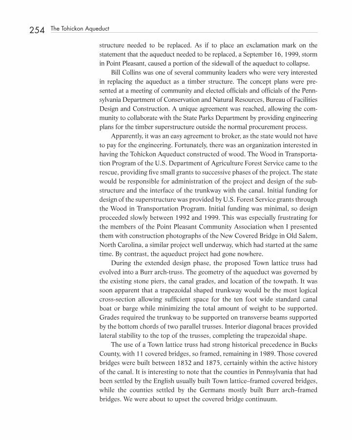
254 The Tohickon Aqueduct
structure needed to be replaced. As if to place an exclamation mark on the statement that the aqueduct needed to be replaced, a September 16, 1999, storm in Point Pleasant, caused a portion of the sidewall of the aqueduct to collapse.
Bill Collins was one of several community leaders who were very interested in replacing the aqueduct as a timber structure. The concept plans were pre-sented at a meeting of community and elected offi cials and offi cials of the Penn-sylvania Department of Conservation and Natural Resources, Bureau of Facilities Design and Construction. A unique agreement was reached, allowing the com-munity to collaborate with the State Parks Department by providing engineering plans for the timber superstructure outside the normal procurement process.
Apparently, it was an easy agreement to broker, as the state would not have to pay for the engineering. Fortunately, there was an organization interested in having the Tohickon Aqueduct constructed of wood. The Wood in Transporta-tion Program of the U.S. Department of Agriculture Forest Service came to the rescue, providing fi ve small grants to successive phases of the project. The state would be responsible for administration of the project and design of the sub-structure and the interface of the trunkway with the canal. Initial funding for design of the superstructure was provided by U.S. Forest Service grants through the Wood in Transportation Program. Initial funding was minimal, so design proceeded slowly between 1992 and 1999. This was especially frustrating for the members of the Point Pleasant Community Association when I presented them with construction photographs of the New Covered Bridge in Old Salem, North Carolina, a similar project well underway, which had started at the same time. By contrast, the aqueduct project had gone nowhere.
During the extended design phase, the proposed Town lattice truss had evolved into a Burr arch - truss. The geometry of the aqueduct was governed by the existing stone piers, the canal grades, and location of the towpath. It was soon apparent that a trapezoidal shaped trunkway would be the most logical cross - section allowing suffi cient space for the ten foot wide standard canal boat or barge while minimizing the total amount of weight to be supported. Grades required the trunkway to be supported on transverse beams supported by the bottom chords of two parallel trusses. Interior diagonal braces provided lateral stability to the top of the trusses, completing the trapezoidal shape.
The use of a Town lattice truss had strong historical precedence in Bucks County, with 11 covered bridges, so framed, remaining in 1989. Those covered bridges were built between 1832 and 1875, certainly within the active history of the canal. It is interesting to note that the counties in Pennsylvania that had been settled by the English usually built Town lattice – framed covered bridges, while the counties settled by the Germans mostly built Burr arch – framed bridges. We were about to upset the covered bridge continuum.
c18.indd 254c18.indd 254 12/18/08 10:23:47 PM12/18/08 10:23:47 PM
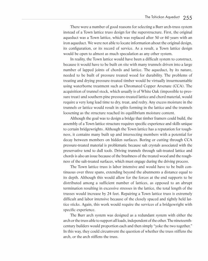
There were a number of good reasons for selecting a Burr arch - truss system instead of a Town lattice truss design for the superstructure. First, the original aqueduct was a Town lattice, which was replaced after 50 or 60 years with an iron aqueduct. We were not able to locate information about the original design, its confi guration, or its record of service. As a result, a Town lattice design would be open to almost as much speculation as any other system.
In reality, the Town lattice would have been a diffi cult system to construct, because it would have to be built on site with many trunnels driven into a large number of lapped joints of chords and lattice. The aqueduct, by its nature, needed to be built of pressure treated wood for durability. The problems of treating and drying pressure - treated timber would be virtually insurmountable using waterborne treatment such as Chromated Copper Arsenate (CCA). The acquisition of trunnel stock, which usually is of White Oak (impossible to pres-sure treat) and southern pine pressure - treated lattice and chord material, would require a very long lead time to dry, treat, and redry. Any excess moisture in the trunnels or lattice would result in splits forming in the lattice and the trunnels loosening as the structure reached its equilibrium moisture content.
Although the goal was to design a bridge that timber framers could build, the assembly of a Town lattice structure requires specifi c experience and skills unique to certain bridgewrights. Although the Town lattice has a reputation for tough-ness, it contains many built up and intersecting members with a potential for decay between members on hidden surfaces. Boring or cutting through CCA pressure - treated material is problematic because salt crystals associated with the preservative tend to dull tools. Driving trunnels through salt - treated lattice and chords is also an issue because of the brashness of the treated wood and the rough-ness of the salt - treated surfaces, which must engage during the driving process.
The Town lattice truss is labor intensive and would have to be built con-tinuous over three spans, extending beyond the abutments a distance equal to its depth. Although this would allow for the forces at the end supports to be distributed among a suffi cient number of lattices, as opposed to an abrupt termination resulting in excessive stresses in the lattice, the total length of the trusses would increase by 24 feet. Repairing a Town lattice truss is extremely diffi cult and labor intensive because of the closely spaced and tightly held lat-tice sticks. Again, this work would require the services of a bridgewright with specifi c experience.
The Burr arch system was designed as a redundant system with either the arch or the truss able to support all loads, independent of the other. The nineteenth - century builders would proportion each and then simply “ yoke the two together. ” In this way, they could circumvent the question of whether the truss stiffens the arch, or the arch stiffens the truss.
The Tohickon Aqueduct 255
c18.indd 255c18.indd 255 12/18/08 10:23:48 PM12/18/08 10:23:48 PM

256 The Tohickon Aqueduct
In this case, the truss and arch were analyzed separately and then also together. Instead of superimposing the arch on the truss, in the computer we actually sus-pended the less stiff continuous truss from three two - hinged arch spans. The Burr arch structural system was designed to support a total weight of 8000 plf.
FIGURE 18-1 The aqueduct consists of three equal spans of 66 feet. (See color insert.)
Although the superstructure was covered and protected with a membrane liner in the trunkway, all wood was specifi ed to be pressure treated to resist decay. The aqueduct, by its very nature and environment, is susceptible to decay caused by moisture derived from condensation, leaks, and splash.
The fi rst design was as traditional as possible using timber - framed connec-tions for splices and to build up the arches. The arches were detailed with mechanically fastened laminated members with shear blocks and stitch bolts with timber washers. The posts and braces were solid timbers, while the criti-cal chord members were glued laminated timber members to ensure quality control and long continuous lengths. To minimize the amount of steel in the structure, posts and braces were notched to fi t notches in the chord members. To provide continuity as the supports, the chords were connected with tradi-tional bolt - o - lightning splices.
The trunkway was fi tted with a membrane liner to ensure the water - tightness of the aqueduct. We suggested that a second layer of wood consisting of large panels be placed on top of the liner to conceal it and provide puncture protection.
An aqueduct is unique because it is uniformly loaded on a constant basis. A vessel traversing the aqueduct displaces an amount of water equal to its weight,
c18.indd 256c18.indd 256 12/18/08 10:23:48 PM12/18/08 10:23:48 PM

and thus, does not increase the load to the structure. Aqueduct structures provide an opportunity to test the concept of load duration, which is central to the design of timber structures.
The Tohickon Aqueduct was bid in 1999 with J.D. Eckman, Inc. of Chester County, Pennsylvania, submitting the low bid of $ 3.1 million. Several timber - frame companies that were heavily courted by the designers declined to submit a bid. Because the low bid exceeded the state ’ s proposed budget, the Depart-ment of Conservation and Natural Resources was directed by the state to develop an alternative design in concrete. Again, on behalf of the Point Pleasant Community Association, Bill Collins petitioned the Department of Conserva-tion and Natural Resources to consider a timber aqueduct. This time it would be a “ value engineered ” version of the fi rst design, bid as an alternative to a concrete structure designed by the department. Again, it agreed, on similar terms, that value engineering would proceed without funding from the state. As before, the Forest Service agreed to fund the engineering design with the condi-tion that the project include fi ber - reinforced polymers to reduce cost. Fiber - reinforced polymers were introduced as a research project of the Advanced Engineered Wood Composites Center at the University of Maine.
The structural system was value engineered to reduce costs by simplifying details, remove requirements for traditional timber framer qualifi cations, and introduce more glued laminated timber into the project, in particular, for the two - hinged arches.
FIGURE 18-2 The arches were replaced through “value engineering” by glued laminated timber.
The Tohickon Aqueduct 257
c18.indd 257c18.indd 257 12/18/08 10:23:50 PM12/18/08 10:23:50 PM

258 The Tohickon Aqueduct
Traditional hand - crafted joinery was deleted, including the complicated bolt - o’ - lightning splices. The three spans were designed to be individual trussed systems identical in geometry. The use of Pennsylvania red oak was deleted as an alternative and the more easily obtained southern pine was specifi ed.
The goal of the value engineering was to reduce construction costs by $ 500,000. The revised project bid in 2000, with J.D. Eckman, Inc. again emerging as the low bidder, was $ 2.1 million, approximately $ 1 million less than the original.
The aqueduct as built is a skewed structure, 201 feet, 10 inches in length with trusses that are 12 feet in height, out to out of the chords.
FIGURE 18-3 The skewed structure is 201 feet, 10 inches in length.
It includes three 66-foot spans with double 6 ¾ inch by 23 3⁄8 inch glued laminated two - hinged arches yoked to a multiple kingpost truss with double 6 ¾ inch by 16 ½ inch and single 8 ¾ inch by 16 ½ inch glued laminated timber chords, top and bottom.
Although the Tohickon Aqueduct was formally reopened on September 15, 2001, and was eligible for nomination for the special Palladio Award Com-petition for Covered Bridge Restoration announced by Clem Labine ’ s Tradi-tional Building magazine, I was persuaded by one of the jurors not to enter it since it was a reconstruction and would not qualify.
The Palladio Awards program launched in 2000 by Traditional Building mag-azine and Period Homes magazine included “ covered bridge repair, preservation,
c18.indd 258c18.indd 258 12/18/08 10:23:51 PM12/18/08 10:23:51 PM

FIGURE 18-4 The chords are pressure-treated glued laminated timber.
FIGURE 18-5 The superstructure was constructed of pressure-treated southern pine.
restoration, or reconstruction completed between 1998 and 2003. ” 1 It appeared that the twin dilemmas of whether the aqueduct would qualify as a covered bridge and whether a total reconstruction of the superstructure in an alternate system would render it unlikely to earn honors. Of course, there were historic examples
The Tohickon Aqueduct 259
c18.indd 259c18.indd 259 12/18/08 10:23:52 PM12/18/08 10:23:52 PM

260 The Tohickon Aqueduct
FIGURE 18-6 The Tohickon Aqueduct was reopened on September 15, 2001.
FIGURE 18-7 The completed aqueduct won a National Timber Bridge Award in 2002. (See color insert.)
of aqueducts with Town lattice and Burr arch structural systems included in Richard Sanders Allen ’ s series of covered bridge books. Some structural engineers favor demolition of a historic covered bridge, only to reconstruct it new, as a viable preservation solution. They argue that the new rebuilt bridge is still historic
c18.indd 260c18.indd 260 12/18/08 10:23:54 PM12/18/08 10:23:54 PM

because the original “ idea ” remains. Certainly, the reconstruction from scratch of the superstructure of a long - gone timber framed aqueduct does not trample on preservation sensibilities. In fact, prior to the Palladio Awards, the Tohickon Aqueduct had won a fi rst place National Timber Bridge Award in 2002 for “ Reha-bilitation of an Existing Bridge. ”
The most remarkable aspect of the Tohickon Aqueduct project was the ability of Bill Collins to move a state agency toward a solution in which they had no initial interest, and then obtain, through negotiation, interested third parties to pay for the engineering.
REFERENCE
1. Cesa, Edward A., News Release USDA Forest Service, January, 2003.
Reference 261
c18.indd 261c18.indd 261 12/18/08 10:23:56 PM12/18/08 10:23:56 PM

263
C H A P T E R1 9 The Current State of Historic Preservation Engineering: One Engineer ’ s Point of View *
INTRODUCTION
A A s we ease into the twenty - fi rst century, it is useful to refl ect on the last 30 years of preservation engineering in the United States, as well as the
current status of the profession. One organization, the Association for Preser-vation Technology, has been at the forefront, raising awareness and providing a forum for a wide spectrum of preservation - engineering issues. There is, how-ever, additional work to be done. Knowledge of preservation and materials technology, increased ability to communicate and exchange ideas, and both successes and failures in practice have enabled preservation engineers to make the necessary judgments in evaluating historic structures. The engineer must be convinced that the structural model in the computer is an accurate repre-sentation of the building, or the building components, being considered. Once that is clear, the application of rigorous analysis, test, and engineering judgment
* This chapter was originally written for the APT Bulletin Vol. XXIX, No. 3-4, Thirtieth-Anniversary Issue, The Journal of Preservation Technology, The Association of Preservation Technology.
c19.indd 263c19.indd 263 12/18/08 10:24:34 PM12/18/08 10:24:34 PM
Structural Investigation of Historic Buildings: A Case Study Guide to Preservation Technology for Buildings,Bridges, Towers, and Mills. David. C. Fischetti © 2009 John Wiley & Sons, Inc.
264 The Current State of Historic Preservation Engineering: One Engineer ’ s Point of View
is necessary to explain why the structure has performed adequately for many years, rather than simply explaining why it is not working.
CURRENT PRACTICE
Within the construction industry it is architects who have assumed leadership in historic preservation. A relatively small portion of structural engineers in private practice consult with architects on building design. Of these, very few provide engineering services for National Historic Landmark or National Reg-ister properties. Often, when engineers, as consultants to architects, respond to the particular program established for a project, the amount of sensitivity brought to bear is directly proportional to the architect ’ s direction. Fortunately, there are numerous projects where the engineer has introduced sensitivity to the benefi t of the whole team. The creative preservation engineer can make a major difference in the overall success of a project by being sensitive to the original historic fabric.
Structural engineers may become embroiled in confl icts over preservation philosophy with architects, clients, approving agencies, state preservation offi ces, and third - party reviewing organizations. In many cases, the engineer ’ s responsi-bility is to ensure that all structural code requirements are met with a minimum of intervention. At the same time, money allocated for testing may be limited.
The tendency is to opt for a retrofi tted independent structural system, such as a steel or concrete frame, which will support all vertical and lateral struc-tural loads, including the building ’ s own weight. This, to many engineers, is the most appropriate solution because it circumvents the issue of the capacity of the existing structure, particularly in buildings with timber structural compo-nents and masonry walls. One would assume that suffi cient fi eldwork would be undertaken to verify defi ciencies and deterioration before replacing the existing structural system with the new. Often, however, this is not the case. In many cases, the decision is based on insuffi cient testing, observation, and analysis.
The philosophy of analyzing the structural system of a building suffi ciently to justify doing little or nothing to the historic fabric is contrary to current practice, which establishes design fees on the basis of how much work needs to be done. An innovative, creative solution including research, job - site obser-vation and measurement, long - term monitoring, and extensive analysis of the existing system and potential solutions may be beyond the fee structure in the standard contractual arrangement between architect and engineering consult-ant, since fees are usually determined as a percentage of construction cost. Unfortunately, an intrusive solution requiring major intervention may result.
c19.indd 264c19.indd 264 12/18/08 10:24:35 PM12/18/08 10:24:35 PM

Our society, which demands immediate solutions, does not tolerate unforeseen costs and does not forgive errors or omissions in construction or design. This forces the design engineer to follow the path of least risk, although this approach may result in the highest overall project cost. For construction fi nancing pur-poses, cost must be predictable. To prevent possible cost overruns due to unfore-seen conditions, the design engineer is often forced into major intervention involving great quantities of new materials, which are far more predictable. The perceived risk extends to the serviceability of the rehabilitated historic structure and is based on “ not knowing. ” Lack of information originates with the absence of a thorough investigative program involving observation, testing, and analysis.
Some architects may be tardy in bringing the preservation engineer on board. Selection of a qualifi ed engineer early in the project is crucial. Accord-ing to Martin Weaver (1993): “ Although structural surveys should involve qualifi ed structural engineers, the conservator is frequently going to encounter evidence of structural problems when no engineer is present and in situations where it is unlikely that anybody is going to be able to return for a second look until much later in the project when it may be too late. ” 1
Some architects may be unsure of which consultants they should hire. Rather than hire both a conservator and a structural engineer, they engage one of them, until it is apparent that the needs of the project dictate additional assistance. As an organization, the Association for Preservation Technology is built on the premise that an interdisciplinary relationship must exist for a project to succeed. The concept of minimum intervention was confi rmed in the special APT Bulletin (XXIII, 1991) on preservation engineering. 2 APT mem-bers have also engaged in interdisciplinary exchanges with such organizations as the American Concrete Institute, the American Society for Testing Materi-als, the American Society of Civil Engineers, the American Society for Non - Destructive Testing, and others. APT is one of few organizations that serve as a forum for technical issues, as well as preservation philosophy.
Many times, it is the conservator and structural engineer working together who strike a balance between structural adequacy and the maximum retention of historic fabric.
PRESERVATION ENGINEERING EDUCATION
In many ways, the engineering profession is slighting preservation practice in that engineering education applies the latest in research and thought to new construction. Very little time is given to historical perspectives relating to the built environment, regardless of when it was built.
Preservation Engineering Education 265
c19.indd 265c19.indd 265 12/18/08 10:24:35 PM12/18/08 10:24:35 PM

266 The Current State of Historic Preservation Engineering: One Engineer ’ s Point of View
Academic training for engineers in North America is lacking in several crucial areas of preservation technology. Courses in history, history of technology, materi-als science, masonry, timber design, and preservation are the minimum core sub-jects for a program in preservation engineering. Other courses, such as industrial processes, would provide students with an appreciation of basic manufacturing methods uncommon in today ’ s construction industry. For economic and environ-mental reasons, many manufacturing methods have disappeared or have been relocated outside of North America. As a result, engineers are not being trained in such areas as pattern making and foundry practice. This puts them at a disad-vantage when such mundane items as earthquake washers must be specifi ed.
Some universities are providing appropriate courses for preservation engi-neering undergraduates. This direction should be encouraged. However, the nationwide push toward mandatory continuing education for engineers presents the best opportunity so far to ensure that practicing engineers are equipped with preservation knowledge and skills. In the United States, preser-vation engineers and trainers must become aware of the professional develop-ment requirements in each state in order to address shortcomings.
Moreover, APT, an organization composed mostly of architects and con-servators and an excellent repository of research and experience, is in an ideal position to help provide continuing education to practicing engineers.
RESEARCH IN HISTORIC STRUCTURES
Historic structures provide the best laboratories for basic research in materi-als. The service life of a material or system can best be observed in an installa-tion that has experienced cycles of thermal and moisture changes, long periods of sunlight, and gravitational force. Accumulated knowledge in preservation technology offers a broader palette of solutions. For example, a structural sys-tem to replace a historic hammer - beam truss in a church could be a steel frame clad in wood, a glued laminated timber frame with bolted connections and steel side plates, or a traditional timber frame with dovetail and mortise - and - tenon connections, or multiple leaves of prefabricated nail plate trusses. The structural system could be built with precast concrete or extruded aluminum box sections, or the frame could consist of fi ber - reinforced plastic resin struc-tural elements simply grained to look like wood. The fi nal decision should depend on what is most appropriate for the project, rather than what is most comfortable for the engineer.
Unfortunately, there is little incentive for the construction - material indus-try to spend money on historic - materials research. Basic research focuses on
c19.indd 266c19.indd 266 12/18/08 10:24:35 PM12/18/08 10:24:35 PM

bringing new products to market. For example, basic research into the load - duration factor for timber design as it applies to timber structures that have been in service for a very long time will not help sell new products for the for-est - products industry. The clay - products industry has little or no interest in doing research into what might be considered archaic systems, such as lime - based mortars, terra cotta, and structural clay tile. Smaller specialty suppliers are still the primary source of replacement materials for preservation projects.
BUILDING CODES
Building codes continue to change in response to disasters. The terrible Trian-gle Shirtwaist Company factory fi re of March 25, 1911, affected building codes in New York City, as well as other North American cities. The 1981 Kansas City Hyatt Regency walkway failure changed the way steel structures are designed and detailed by shifting more of the burden for the design of shop details to the engineer of record. As a result of Hurricane Andrew, which bat-tered south Florida in 1992, codes have been complicated with various wind - load factors and unrealistic loading conditions in order to prevent future damage from a similar storm, as if a defi ciency in the code were the problem (studies have shown that the code in South Florida was more than adequate, had it been followed, to produce buildings constructed well enough to resist wind forces generated by Hurricane Andrew). The Northridge, California, earthquake of 1994, as well as the one in Kobe, Japan, a year later, will greatly affect seismic requirements of the building codes to be published in the next few years.
New textbooks, handbooks, design codes, and building codes regularly replace the old. In recent years, there has been an accelerated transfer of basic research regarding the application of loads — wind, snow, and seismic — from the graduate - school laboratories directly into model building codes. Building codes are not the proper forums for this exchange of ideas; rather, they should be a distillation of the best and simplest requirements, which have been proven. Only time will tell how these more complex building codes will affect the exist-ing stock of buildings as they become candidates for restoration, rehabilitation, or demolition.
Instead of being of repository of minimal, yet simple, requirements for the construction of the safe structures, building codes are prescribing complicated methods of analysis, forcing engineers into a “ cookbook ” methodology from which they cannot vary, except at their own peril. An engineer evaluating the seismic resistance of a historic structure must fi t in into a certain building type.
Building Codes 267
c19.indd 267c19.indd 267 12/18/08 10:24:36 PM12/18/08 10:24:36 PM

268 The Current State of Historic Preservation Engineering: One Engineer ’ s Point of View
In a 1990 issue of Wood Design Focus , Arlo Ceccotti presented an earthquake - performance challenge to researchers, code writers, and designers:
It is evident that thorough knowledge and planned balance of the positive and negative aspects will yield a proper design that guarantees structural safety at a reasonable cost.
Researchers have the challenge of quantifying the factors that yield ductile behavior and energy dissipation in the structure. They can determine how to design and detail connections that lead to ductile systems, rather than brittle failures.
Code writers have the challenge of combining the often disparate results of research. They must present a few relatively simple and conservative design rules, which are easy to apply, for the most common structural forms (those with known ductility and dissipation levels). Yet, for less common structures, for which experience has demonstrated good structural performance, code writers must provide simple rules or guidelines based on the engineering judg-ment. Designers, have the challenge of fi nding the classes, creating the most convenient design from technical and economical points of view. 3
Having participated in a building code review committee, it is apparent that code writers ultimately accept the fi ndings of academia, possibly due to liability concerns, As Ceccotti has explained, these issues will not go away, and their impact on historic structures cannot be denied. Proposed seismic provi-sions for building additions will affect the historic preservation and the renova-tion and rehabilitation segments of the construction industry. The application of complicated seismic requirements, which are subject to wide interpretation, will cause the demolition of many existing buildings. For example, to deter-mine the seismic resistance of an existing building accurately, the unit weight and shear capacity of the existing masonry must be known. This may require extensive testing in the fi eld to obtain design values to be used in the analysis, for which owners often are not willing to pay.
Seismic strengthening should not automatically require the installation of a retrofi tted steel or concrete structural system into a building. Bernard Feilden (1982) has discussed methods of strengthening historic buildings to retain as much historic fabric as possible: “ Examination of earthquake damage shows that bonding of walls together at the corners is vital, together with the tying of fl oors and roofs to walls. The insertion of tensile reinforcement with some degree of prestressing to bond elements together give the masonry of historic buildings greater earthquake resistance. ” 4
Photographs of heavily damaged buildings in Friuli, Italy, after the 1979 earthquake demonstrate the effi ciency of temporary timber bracing. Similar bracing can be employed during repairs to stabilize tall masonry walls.
Many owners faced with rehabilitating or adding to an older or historic structure will elect to demolish when faced with engineering fees for evaluation
c19.indd 268c19.indd 268 12/18/08 10:24:36 PM12/18/08 10:24:36 PM

or potentially unknown construction costs required to bring a building into conformance with the seismic code.
ENGINEERING JUDGMENT
Preservation engineering is quite different from designing new structures. Free-dom of choice is eliminated. The preservation engineer must evaluate an existing system, which in some cases was not designed but merely proportioned accord-ing to a pattern book based on rules of thumb. Meeting the requirements of the building code is not the same as ensuring a safe structure. Structural engineers must make the judgments necessary to keep a historic structure in service when parameters appear to fall short of minimum code requirements. For example, in reviewing the capacity of an existing structural member, many parameters com-plicate the process. Size, span, and spacing of members are dictated by the struc-ture. It is the engineer ’ s task to determine the size, orientation, material, properties, and boundary conditions of all the structural elements in an existing building.
It must be recognized that structural members that are determined to be “ overstressed ” may in fact be perfectly safe. It is important to evaluate the basis for the conclusion. The loads assumed for design should be reconciled with the actual loads. A safe fl oor structure should not fail in bending due to the actual loads imposed, but excessive defl ection, excessive vibration, or a lack of stiff-ness should not automatically categorize a fl oor structure as unsafe.
Strict defl ection limitations should be set for fl oors that support plaster ceilings in lieu of wood, or tin ceilings, or no ceilings at all. For comfort, the defl ection limitation set in most building codes for fl oors, no matter what the ceiling, as 1/360th of the span.
Today we have the technology to analyze loose - laid stone walls, obtaining a quantitative methodology that utilizes lateral earth and hydrostatic pressures, unit weights, friction and roughness coeffi cients, shape factors, and wall dimen-sions. Yet engineers insist on building replacement stone walls with reinforced concrete faced with a stone veneer while knowing that the serviceability of a loose - laid stone wall, properly constructed of a suitable stone material, can easily outlast the reinforced concrete wall.
CONCLUSION
Preservation engineers dare to meet challenges that engineers engaged in new construction never encounter. The knowledge that is being accumulated through these experiences needs to be shared with engineers entering the fi eld through
Conclusion 269
c19.indd 269c19.indd 269 12/18/08 10:24:36 PM12/18/08 10:24:36 PM

270 The Current State of Historic Preservation Engineering: One Engineer ’ s Point of View
undergraduate education and with practicing engineers, who must continue to educate colleagues in architecture, government, and the community about proper preservation techniques so that the body of knowledge and the physical inventory of historical structures will remain for those who follow.
REFERENCES
1. Martin E. Weaver, Conserving Buildings, Guide to Techniques and Materi-als (New York: John Wiley & Sons, 1993), 5.
2. Stephen J. Kelley, “ Overview: The Role of the Engineer in Preservation, “ APT Bulletin XXIII (1991): 6.
3. Arlo Ceccotti, “ The Earthquake Performance Challenge, ” Wood Design Focus 1 (1990): 3.
4. Feilden, Bernard M. Conservation of Historic Buildings (New York: Butterworth & Co. Ltd., 1982), 104 - 105, 121.
BIBLIOGRAPHY
Fitch , James Marston. Historic Preservation: Curatorial Management of the Built World ( New York : McGraw - Hill , 1982 ), 128 – 129 , 146 – 147, 350 – 355.
Harvey , John. Conservation of Buildings ( London : John Baker, Ltd. 1972 ), 116 – 125 .
Hosner , Jr. , Charles B. Preservation Comes of Age – From Williamsburg to the National Trust, 1926 – 1949 ( Virginia : The University Press of Virginia , 1981 ).
The Preservation Press, National Truss for Historic Preservation , Preservation: Toward an Ethic in the 1980 ’ s ( Washington, D.C. : National Preservation Conference Williamsburg, Va. , 1980 ).
c19.indd 270c19.indd 270 12/18/08 10:24:37 PM12/18/08 10:24:37 PM
271
Index
AASHO. See American Association of State Highway and Transportation Offi cials
Abington, VA, 56ACI. See American Concrete InstituteAdair, Kenneth, 188African American, 125Ahoskie, NC, 87AITC. See American Institute of Timber ConstructionAlison, Olivia, 174Allen, Richard Sanders, 260American Association of State Highway and Transportation
Offi cials, 36American Concrete Institute (ACI), 25, 29, 265American Institute of Timber Construction (AITC), 28American Plywood Association (APA), 34, 119Ames Dial Defl ectometer, 85Anderson, Al, 56, 248Anthony, Ron, 54, 143APA See American Plywood AssociationAppalachian Mountains, 31Aqueduct, 47Archeological evidence, 125, 132ASTM, ix, 7, 76, 84–85, 131, 173The Atlantic Monthly, 26Auchumpkee Covered Bridge, 109, 216, 217AutoCAD®, 135
Beaufort, SC, 91, 104–105, 170, 176Bending stress, 16, 18–19, 65, 81, 152–153, 201Bethlehem, PA, 123, 241, 245, 246, 247Blake, Charlie, 47, 135Blake Moving Company, 46–47, 50, 135Blue Ridge Timberwrights, 48, 56, 133, 248Bolt-o-lightning, 49, 256, 258Bolts-plus, 105–106Bow’s Notation, 36Brazil, 33Brick, 7–8, 43–46, 76–79, 86, 99–103, 125, 182, 190Brick masonry, 6–8, 44–45, 75–76, 97, 102–103, 127–128,
160, 178, 187Brick piers, 43
Bridges, 27, 35–36, 63, 211–226 covered, 49–56, 207–210, 219–220, 227–239, 241–251 highway, 11 historic, ix, 11–12 one-lane, 11 two-lane, 11Buie’s Creek, NC, 101Bull, Peter, 48, 121Bunker Hill Covered Bridge, 49, 219–225, 246Burnside Plantation, 50Burr, Theodore, 27, 212–214Bush, David M., 193Buxton, NC, 183, 201
Cable-stayed, 233, 234, 236CABO code, 29Caisson foundations, 30Campbell University, 101Camp, Billy, 103Canada, 15, 57, 68, 149, 152Cape Hatteras Lighthouse, 181–205Carteret, John, 123, 245Cast iron, 6, 67, 211Catawba County, NC, 49, 219–221, 224CCA. See Copper Chromated ArsenateCeccotti, Ario, 32, 268Certifi ed rehabilitation, 2, 69, 83Chapel Hill, NC, 45Charleston, SC, 8, 10, 30–31, 48, 52, 98–109, 115, 122,
152–157Charlotte, NC, 49, 224Chesterfi eld Associates, 234Chesnut, Sarah, 54Chowan County Courthouse, 18, 152Church of the Virgin Mary, 190–191Civil Engineering, 23–24Civil War, 54, 115–116, 125, 219, 225Clay tile, 30, 102, 267Code Mandated Vibratory Analysis, 29Collins, Bill, 47–48, 253–254, 257, 261Computer model, 11, 64, 66, 154, 220
bindex.indd 271bindex.indd 271 12/18/08 10:05:13 PM12/18/08 10:05:13 PM
Structural Investigation of Historic Buildings: A Case Study Guide to Preservation Technology for Buildings,Bridges, Towers, and Mills. David. C. Fischetti © 2009 John Wiley & Sons, Inc.

272 Index
Concord, NH, 18, 152Concrete Reinforcing Steel Institute (CRSI), 6, 88Connecticut, 50, 115, 192, 228, 234, 246Conservation, viii, 41–56, 115, 149–168, 178–179Continued professional development, 38Continuity, viii, 11, 25, 46, 63, 106, 154, 176,
217, 233Contour interval, 4, 63Copper Chromated Arsenate (CCA), 157, 163, 255Corning Glass Museum, 80Cornish-Windsor Bridge, 227–239Count Zinzendorf, 124Crack monitoring, 4–5Crawl space, 43–46, 74–78, 84, 100, 127Cribbing, 43, 54, 107, 109–110, 190, 198–199, 202CRSI. See Concrete Reinforcing Steel InstituteCyclic loading, 10, 18, 64, 152
Darlington, SC, 43Darrah Hall, 52–53Defl ection, viii, 2–6, 16–19, 45–46, 63–65, 151–155, 165,
231–232, 269Delaware Canal, 47, 253De Niro, Robert, 33Design philosophy, 36, 208Diamond Shoals, 184Differential settlement, 123Dorton Arena, viiDrift pin, 12Drill rig, 84, 131, 134, 135DuPont, William, 139Dutchmen, 49, 52, 54, 147, 156–157Dywidag®, 234
Eagle Block Hotel, 87–90Economic Recovery Tax Act, 58Engineering education, 36–37 preservation, 265–266Engineering judgment, 17, 33, 64, 150, 269Engineer of record, 3, 25–27, 33–35, 42, 161, 267Epoxy, 52–53, 67, 76, 119, 146–147, 162–165, 201Equilibrium moisture content, 8–9, 59, 255
Factor of safety, 17, 135, 194, 201Fees, 22, 28Feilden, Bernard, 268Fiber saturation point, 9, 59–60Fish plates, 61Flat-plate, 87–90Fletcher, Bela J., 228Florida, 34–35, 55, 188, 267Fore, George T., 91–92, 94, 103, 154–155, 186, 205Foundation Services, Inc., 134–135Freeze-thaw, 176Froehling & Robertson (F&R), 81, 85, 131, 156, 174Fungi, 161, 162
Garcia, Antonio M., 24Garrett Hotel, 87Geotechnical testing, 84Globalization, 55Glued laminated timber, 16, 48, 54–56, 118, 149,
152, 160–166, 210, 227, 231–237, 248, 257–259Glulam, 149–168, 231, 232–239, 248Goddard Bridge, 215Goldberg, Mike, 48, 120Grade beams, 138, 188, 195Grading rules, 9, 60, 248–249 grading rules expert, 9Graham, Tommy, 52, 54, 156Grant writers, 42Graphic analysis, 36Graton, Arnold, 49–51, 54, 109–110, 145, 216, 224–225Graton, JR, 109, 216Graton, Milton, 216, 229Greensboro, NC, 46, 134–135, 233Griphoists®, 110, 111Ground modifi cation, 42
Halma, Sidney, 224Hand-auger borings, 84Hanisch, Max C., 159Harshman, Scott, 134Haupt, Herman, 21, 27, 49, 211–219, 225, 246Hawaii, 31, 33Hayward Barker, Inc., 134, 135Henderson, NC, 50Hillman Incorporated, 189, 198Hillsborough, NC, 19, 153Historic Covered Bridge Preservation Program, 211Historic District Commission, 45Historic Preservation Offi ce, 64H.M. Kern Corporation, 135Horizontal defl ection, 45–46, 155Horizontal shear, 11, 16, 60, 65, 150, 161–162, 217Hurricane Fran, 49–50, 58Hurricane Hugo, 31, 153–154Hyatt-Regency, 25, 267
IASM. See International Association of Structural MoversImproved lattice, 49, 219–220, 222–223, 246Increment borer, 9, 59, 76–77In Situ, 175International Association of Structural Movers
(IASM), 43International Building Code, 3International Chimney Corporation, 181, 194, 195,
204, 205Iron dogs, 61
Jacking, 42–44, 98, 164, 205, 218James Madison’s Montpelier, 54, 62, 139–147Jeanes, John, 144
bindex.indd 272bindex.indd 272 12/18/08 10:05:15 PM12/18/08 10:05:15 PM
Index 273
Jobsite observation, 44, 129John Milner Architects, Inc., 126, 130Joints dovetail, 60, 63, 68, 152, 266 tenon, 60, 63, 68, 152, 157, 266Joist hangers, 11, 44, 60, 146, 164Joist substitutes, 16, 18, 68, 168
Kivett Hall, 101Knots, 63, 215, 231, 249Kobe, Japan, 29, 105, 267
Laminated veneer lumber, 18, 54, 68, 146–147Lateral bracing, 5, 66–67, 78, 107–109, 138, 209Larson, John, 130, 131, 138, 242LEED, 158Lehigh, PA, 241, 247Lewandowski, Jan, 47, 49, 233Lime mortar, 7, 100, 101, 107, 170Live load duration, 17, 64, 151Load duration, viii, 13, 17–18, 64, 151–152, 257Load and Resistance Factor Design (LRFD), 29, 151–152Load testing, 4, 6, 65–66, 208Long-term defl ection, 35, 46LRFD. See Load and Resistance Factor DesignLumber grades, 49
MACTEC, 195, 204–205Magee, Tom, 121Market Hall, 10, 48–49, 115–122Marl, 31Maxwell diagram, 36MBM Construction, 48Mesick, Cohn, Wilson, and Baker Architects, 54, 144Methylene chloride, 163Midway Plantation, 50Miles Brewton House, 52, 152, 156Milner, John, 126, 130Mini piles, 130, 131, 134–135, 137–138Modulus of elasticity, 19, 46, 66, 97, 174, 208, 249Moisture content, 8–9, 18, 46, 54, 59–60, 67, 76, 249Moisture penetration, 8, 13Montague Building, 18–19, 71–90, 152Montezuma Castle, viiMoorfi elds, 19, 153Moravians, 123, 123, 125, 241, 245Morris Island, 115Mortar, 6–7, 30, 76, 92, 100–101, 136, 170–171, 267MTMA Design Group, 186, 193Museum of Early Southern Decorative Arts, 243
National Design Specifi cation for Wood Construction (NDS), 28, 67, 81, 208
National Park Service, 64, 86, 172, 181, 186–187,193, 204
Negligence, 26, 33
The New Jersey Rehab Code, 3NC State Building Code, 81. See also North Carolina State
Building CodeNDS. See National Design Specifi cation for Wood
ConstructionNervi, Pier Luigi, 36New London, CN, 192Newport, NH, 87, 89North Carolina State Building Code, 3, 29, 221.
See also NC State Building CodeNorth Carolina State University, 49, 72, 74, 83, 56, 183Northampton County, 241, 247Northridge, CA, 29, 267
Old-growth, 10Old-growth forest, 63, 158Old Salem, 56, 123, 241Oppermann, Joseph K. 115Orange, VA, 54Original plans, 5, 185Outer Banks, 183Oven-dried weight, 9, 59, 85, 249Owen-Thomas House, 174Oxford Limestone, 52
Palladio Awards, 122, 258, 261Palmer, Timothy, 27, 248Partridge, Reuben L., 210Penetration tests, 131Peshtigo, 159–160Phillips, Charles A. 129Phillips & Oppermann, 115, 130Piles pencil, 134 piles, 134 pin, 134Pilkey, Orrin H., 183, 193Pinckney, B.J., 94Pith, 60Pittsburgh, PA, 189, 190Plan stamping, 54–56Pocopson Industries, 48Point Pleasant, PA, 47, 253–254, 257Pooley, Bruce, 28Portland cement, 92, 100, 135, 171, 177, 179,
188, 200Preservation engineers, 18, 68, 168, 263, 269Preservation philosophy, 16, 41–42, 68–69, 150,
227, 238, 264–265Purlin, 9, 16, 59, 63–64, 142, 150, 168
Rehabilitation, 2, 68–72, 115, 161, 194, 228–232, 235Relative humidity, 8–9, 59, 93Replacement-in-kind, 18, 68, 152, 155–156, 168, 230Resistance drilling, 54, 143Restoration, 6–7, 49, 72, 91, 125–127, 135–138, 229
bindex.indd 273bindex.indd 273 12/18/08 10:05:15 PM12/18/08 10:05:15 PM

274 Index
Restoration mason, 42, 120Riveted iron truss, 47Riveted steel structures, 12Roller bearing, 46Romanesque Revival, 74Ruscon, 109
Saw kerf, 60Scarf joint, 60–62, 67, 156Screws, 67–68, 83–84, 158, 164Season checks, 60The Secretary of the Interior’s Guidelines, 161, 165. See also
The Secretary of the Interiors Standards for Rehabilita-tion
The Secretary of the Interiors Standards for Rehabilitation, 2, 68, 73, 92. See also The Secretary of the Interior’s Guidelines
Seismic design, 29–33Seismic Hazard Exposure Group, 32Scissors trusses, 44–46Shear blocks, 61, 120, 230, 256Shear heads, 77, 88, 89Shop drawings, 25, 54, 55, 161–163Shoreline erosion, 183, 184Shoring, 41–43, 54, 74, 77–79, 115, 134, 197–198,
203–205, 210Shrinkage radial. 9, 59, 66 tangential, 9, 59, 66 volumetric, 9, 59Sickles-Taves, 103, 172, 176Simbel, Abu, 191, 192Simmons, Albert, 98Simplifi ed engineering, 21–40S & ME, 100, 103, 104, 106Smith, J. Stephen, 109Snowdrift, 27–28Snow, J.P., 228, 229Southern pine, 10, 18–19, 46, 81–82, 127, 157, 215, 225,
232, 248, 259Specialty contractor, 41–56, 138Specifi c gravity, 9, 59, 66–67, 76, 85, 172SPIB, 248, 249Split Rings, 67Standard penetration, 84, 105, 131Statically indeterminate, 37, 213Steel, 6, 12, 25, 77–79, 83–90, 99, 136–142, 162–164, 166,
197–203, 264–268Steeple, 23, 52, 93, 99, 109, 113, 123, 153–158Stetson, Dexter, 185, 195St. Helena’s Episcopal Church, 91–113, 170St. Helena Island, SC, 52Stick, David, 185St. Michael’s, 31, 52, 99, 153, 156–157St. Philip’s Episcopal Church, 101
Stone, vii, 6, 15, 33, 42, 57, 154, 184–187, 195–199, 230, 269
Storrs, J.W. 229Strain gauges, 4Stucco, 8, 92, 102–103, 176–177Structures existing, viii, 3, 10, 30, 37–38, 87, 159 historic, 1–14, 17–18, 64, 151–152, 266–267Surveyor, 2, 42, 76, 208, 245
Tabby, 92, 103, 169–179Tasker, James F., 228, 237Tax credit, 86–87Tax credit status, 74, 83Tedesko, Anton, 23Telfair Museum of Art, 174Tenon, 60, 63, 68, 152, 157, 266Termites, 69, 161, 162Terra cotta, 6, 267Testing laboratory, 156, 173, 208Thomaston, GA, 109, 216Thermal movement 4, 13Timber, viii, 4–6, 8–13, 15–19, 28, 47–51, 57–70, 85–86,
149–168, 221–225, 231–232Timber design, 8–11, 15–18, 28–29, 58–60Timber framer, 42, 47–56, 64, 120–121, 224, 232, 255Timber Framers Guild of North America, 120, 253Timber joinery, 61–63, 139Tinius-Olsen, 156Tohickon Aqueduct, 47–48, 253–261Tongue and groove decking, 243Topographic plan, 4, 63Town, Ithiel, 27, 211, 214–219, 222, 228, 246Town lattice, 47–51, 212, 214–219, 227–229, 238, 241,
247–248, 253–255, 260Treenails, 60Triangle Shirtwaist Company, 267Trinity United Methodist Church, 43–44Trunnels, 48, 60, 127, 215, 217, 220, 255Tudor arches, 159, 162–165Tuttle, Harry, 33
Ultimate stress design, 29Underpinning, 42, 74, 106, 125–127, 130–131,
134–135, 138Underwriters Laboratory, 25United Church of Chapel Hill, 44–47United hydraulic system, 181, 202, 203Use factor, 155Utica Road Covered Bridge, 213
Wachovia, 124, 245Wake County, NC, 50, 84Walker Building, 18–19, 152Watagua Club, 74
bindex.indd 274bindex.indd 274 12/18/08 10:05:16 PM12/18/08 10:05:16 PM

Index 275
Watagua Hall, 71–90Weaver, Martin, 265Wernwag, Louis, 27, 248Whipple, Squire, 21, 27, 219White, Percival, 26White’s Mill, 56Wilson, Barrett, 193Winston-Salem, NC, 115, 125, 130, 243,
245, 249Wood Design Focus, 32, 268
The Wood Handbook, 9, 60, 67Wood scientist, 42, 54, 143Working stress design, 29, 152Wright, David W., 228Wrought iron, ix, 6, 11, 66, 153, 158 nails, 11
Yates Mill, 49–50, 58, 70Yates Mill Associates, 49Yline, A., 28
bindex.indd 275bindex.indd 275 12/18/08 10:05:17 PM12/18/08 10:05:17 PM