Embed Size (px)
Citation preview
DEPARTMENT OF THE NAVY
DAVID TAYLOR MODEL BASIN WASHINGTON 7. D.C.
STRUCTURAL DESIGN LOADS AND CRITERIA
FOR 500 TON HYDROFOIL SHIP
(A study of an approach to this goal)
STRUCTURAL MECHANICS LABORATORY TECHNICAL NOTE
SML-700-2
March 18, 1963
Encl (1) to DTME3 J_tr Ser 7
ABSTRACT
This study discusses the factors to be considered as
they would apply to the structural design of a 500-ton, go-knot
ship. A second section covers suggestions' for theoretical
development to obtain an understanding of the phenomenon
involved. The third portion discusses full scale test craft
program objectives while the final section concerns materials
for the hull and hydrofoils, The program envisioned to
establish design loads will pursue development of theoretical
predictions with verification by full scale tests.
INTRODUCTION
The Bureau of Ships assigned to the Model Basin
the task for development of structural design loads a,nd
design criteria as applied to a fSOO-ton, go-knot hydrofoil
ship. A research program is presently underway to explore
some aspects of this problem. The following review was
carried out as a background study to be used for amplifying
the present program, reference 4, and modifying it where
it would appear necessary,
DESIGN CONCEPT
After the PCH demonstrates its capability, it
is probably that operational requirements will be developed
for both larger and faster hydrofoil ships. The design of
such ships will require a refinement in the assumptions and
criteria used to permit optimizing performance with a rational
design procedure. Report, reference 1, presents
a theoretical discussion of, such structural design
requirements based, in part, on airplane design practices. Paper, reference 2, gives an abbreviated summary of these
considerations. Paper, reference 3, is still another note on the many new considerations in design of hydrofoil
ships in contrast to present surface ship methods. All of these reports indicate an urgent need for reliable
load data. A principle objective of this program is to
obtain verification of these procedures,
The concept for a 500-ton, PO-knot ship is
still vague, The actual mission of such a ship will influence the design criteria, For instance, the sea state to be negotiated at a given speed, and possibility
of topside weapons and electronics will effect the struc-
tures through the hydrodynamic stability requirements,
However, this program to develop criteria is to be broad
so that these variables can be covered by the data to be
obtained. The concept of the 500-ton, go-knot ship
structure in this report is developed to illustrate the
relations of various parameters and will be subject to
changes to suit a particular set of requirements,
The general characteristics of a 500-ton ship
capable of 90 knots have to be established, based on
existing designs and test results. Incidental data on arrangements, weight of equipment, machinery, etc., can
be derived from either or both the PCH and AGEH Contract
plans, which are available. The hull structure and weight will have to be scaled and modified according to informa-
tion developed by this program,
Some questions still exist as to the optimum
hydrofoil configuration for the 500-ton ship, The SEA LEGS and PCH have the main lifting surface aft and supported by
two struts.
The AGEH design has hydrofoils port and starboard, just
forward of amidship, to support most of the weight,, The AGEH also has a large hull overhang forward which may be
unacceptable. This test program will help to provide a basis to establish an acceptable design for the 500-ton
ship. The hydrofoil configuration might be scaled
from an alternate high speed supercavitating foil design required for the AGEH under the rules for awarding contract by Bureau of Ships. The supercavitating foil design could also be based on tests carried out by the Bureau of Ships test craft %RESH Ifs for evaluating supercavitating hydrofoils,, The Hydrodynamics Laboratory can assist with this selection,
The structural design for the lifting foils and the supporting struts is limited by hydrodynamic
considerations which will present very serious problems for a go-knot %upercavitating" ship, Considerable problems also arise in the shafting inside the struts
during turns when struts are highly loaded and deflect, bending the shafts. The connections between the struts and lifting foils bave to be made compatible with mini- mum drag design and the propulsion gearing has to be
incorporated at this point also. This location at the juncture between foil and strut is usually the highest stressed material,, It can be seen that any structural study of these members has to follow and be closely coordinated with hydrodynamic design criteria.
The structural design loads and design criteria to be developed must accomplish the following:
a. It must be possible to analyze the hull and hydrofoil structures developed for the 500-ton, go-knot
craft. These calculations are to cover normal operating
3
loads in kaves as determined by theoretical approach
such as in report, reference '1, and verified by test
program.
b, It must be possible to calculate ship survival from unusual loads such as impact with non-yielding obstacles while flying and from underwater explosions;
CO Procedures are to be included for approximate checks of hydroelastic and vibration problems during
the preliminary design formative stages of ship, Use of exact procedures for these calculations shall be indicated where developed and the relative accuracy
noted, An explanation of the use of the data
presented is to be shown as it would apply to the 500-ton ship, It is recommended that upon completion of this assignment, sample design calculations for this ship be included in the appendix,
The summary or appendix is to have a series of charts, tables, or other means of showing data so that the the designer can enter them with operational require- ments such as limiting acceleration, speed, deadrise of hull, and determine parameters like hull clearance or wave
induced hull pressures for a range of sea states. If the data is presented in form of equations, th,ey should be solveable by use of desk calculating machines and without
use of complicated mathematics,,
THEORETICAL CONSIDERATIONS
Paper, reference 1, presents a proposed rational procedure for the ship structural design. Further informa- tion needs to be developed on the actual ship environment and related response of the ship with the loading involved,
4
Additional areas needing theoretical investigation are actual foil spanwise lift distribution, autopilot control,
impacts with objects in water, weapons effects, and vibra: tion considerations,
Hull During take-off and landing operations, and
on occasions when ship meets waves larger than the design height, the hull of the ship will slice through waves and crests, An autopilot failure could cause the hull to be
rldroppede' back into the water at high speeds, either on even keel. or at some inclination, During take-off and
landing operations, in large seas, the ship will ship
"green water88 aboard, The loadings from these conditions
(Load distribution) have to be established, Various size and weight of objects may be at
the water surface in harbors, A procedure is required to
permit assessing of damage to hull which would result when such objects are hit by the hull or the struts, As
an examples what mass (size) would displace the hull-st,rut
foundation structure beyond elastic deformation? Impact
loads from such objects need to be estimated, The impact forces on the hull passing through
wave crests need to be defined in terms of both magnitude, distribution, and duration, As an example> it should be
possible to predict the load on a panel of shell plating and the total force at the bow and the duration of this condition, With this data, a method for determining the
,overalL effect on the hull girder is to be shown with a procedure for estimating the whipping stresses along the hull,
5
Hydrofoils
The steady-state Lift and drag forces on
hydrofoils and their supporting struts are determined
by hydrodynamic calculations, Forces on the hydrofoils
and the struts (Lateral areas) during turns are also
primarily hydrodynamic calcuLationsO However, the exact
spanwise distribution of these loadings and possible variations in turns, which are not steady state normally,
is not estabLished and makes further development 0%
hydrodynamic procedures desirable. The loading on foils wi.PLl not be steady state
when the ship is proceeding through waves,, The ship
commander will have an optlon in autopilot adjustment to regulate the vertical accelerations of the ship and so control foil lift (through foLiE flaps) and optimize ship operation under existing wake conditions, This acceptable
accelerationS value has been considered to be less than one-half G for personnel operation efficj,ency. With this
control, wave impacts on huJ_I w1l.l. 'be a function of' sea
state and designed hull clearance of ships.,
Dynamic Factors Based on the given steady-state Loading of
foils, a procedure has 6 .+&$I developed to determine the
dynamic factor to account for operation in random seas., This dynamic action wiLk come about whenever the nominal. wave heights become greater than the designed hull
clearance plus about one-half foil submergence, The
results of this study should show in form of tables,
graphs B or nomographs, the variation of s@CDc loading under
various sea states and hull clearance with an approximate
number of each "G"* during a given period,
6
The maximum strut loads will be during turning
of ship. Based on hydrodynamic data to be requested,
charts9 tables, graphs or other means should be developed
to show the factors above static load, which will result
i.n turns of various rad1.i and at di.fferent speeds, Thi.s
data wil.1 have to include both the side load on the struts
and the increased loads transmitted to the strut by hydro-
foils in turns.
Hydrofoil Explosive Loading
A combat operational ship will be subject to
explosive loadings from its own weapons or enemy action,
The effects of these poss%bilities need to be evaluated
for underwater weapons with respect to:
a, The effect on the foil. structure and foil lift,
b, The effect on struts and huLL foundations.
The hydrofoil. li.ft is developed by flow circula-
ti.on around the selected shape and by a cavity for the
supercavitatlng Zype foil. Wi,th the hollow foil construc-
tion (used for PCH and AGEH), the foi.1 plating and
possibly the whole foil could be deformed, A method to
predict the extent of such damage, and in case of the
supercavitating foil, the effect of collapse of the
cavit.y needs to be developed, The explosive loads on the foils will be trans-
mitted to the hull structure, Th:is combined foil I,if t
change and strut column force prediction procedure will
be requi.red to determine the requirements for the strut-
hull foundation design.

The results of this investigation must be
condensed to procedure for predictions of high explosives
or nuclear weapons effects for the full, range of possible
a0tacl-c severity, To assess the lift change it will be
necessary to predict the ex,tent) of foil damage or dis-
tortions also o
Ob$tacl.es
There have been reports of” the Russian hydro-
foils running aground i.n the rfvers, back.j.ng off and
continuing their trip. A Supramar hydrofoil (surface
piercing with steel foils) hit a solid railroad tie and
sliced it in half at 45=-degree angle, In this case the
pieces hit the propeller and bent it so as to cause
excessive vibration, There were cases of the impacts
where the Supramar hydrofoil, ferry hS,t a floating Log
causing foils to be forced out of” adjustment, but without
destroying the foils, The LCW hydrofoil test craft
‘“HalobatesPswith submerged, pivoted, forward foi,ls hit a
dock and broke the foil pivot and I.ost the foil, probably
without damage to t.he foil itself. It, should be noted
that. the extent of foil or” hull. damage from immovable
objects depends a great deal on how strong the foil-hull
foundati.on is de si,gned ‘,
Unless th,e hydrofoil-,st~ut is made yetractable,
it wi.l.1 project out. beyond the con.f”ines of the hull. As
in case of ‘iHal.obatesP”g this will present a problem comi.ng
al.ong side and going aground in shallow wat;er as En the
case of” Russian experience, When the struts and foil are
retractable, they are not. as rigidly supported and wi.l.1
probably deflect if a large imrnobil,e object is hit, In
this event i.t will require adjustment of foil, but will.
not mean that t.he ship will be i,ost,
8
Hydrofoil (Obstacles)
In addition to normal operating loads, the
hydrofoils or supporting struts could hit floating
objects in the water where the ship is foil borne, As
suck-i objects are more likely in harbors9 these possi-
bi.lir,ies would be at less than normal speed, The effect
of resultant impact Es a, function of the size of ship
and direction of impact, A procedure is required to
permit an est.imate of the mass of a floating object
and the resulting forces on hydrofoil. structulaes from
an i.mpact 0
The hydrofoils extend for a considerable
distance below the bottom of shl,p “s hull, Thi,s added
draft makes it possible that the ship would run aground
on occasion just before take-off in shal,low harbors.
It is possible that the ship ~1.13. hit some fixed under-
water obstruction when flyfng also, In the event that
t.he bottom. of channel i.s yl,eI,ding, a method shtiuld be
provided to determine the drag forse on strut while
the ship is being stopped, If th.e underwater object
i.s unyielding, a procedure for an estimate of the impact
force is needed to design the huI.I, fou.ndation of st.rut,
Hydrofoi.I, (Vibration)
The ba.sic design of hyd~ofo~,I~ structure has
been different. on each boat 01” sl~lp built, There have
not been any noticeable hydroelastic problems except on
propellers Q However3 the experience is with subcavitat-
ing hydlaofoil shapes which are not subject to as high
loading as proposed on hfghes spe:3d supercavitating type,
9
The supercavitating foil sections are also relatively
thin and flexable,
A study of proposed hydrofoil designs using
supercavitating shapes is required to determine natural
frequency and relative SLutter psobl.ems. On the basis of this survey either an exact, or a simple, short
approximate procedure is to be developed to permit a
check of proposed new designs for problem areas before
the design has progressed too far.
Problems could arise on supercavitating foils during take-off before a stable cavity can develop,
The procedure to be developed should permit a check of
vibration with speed and to indicate if and what resultant transitlon conditions could exist, The effect of a preload as on foil strust is to be determined and included in the
design method e
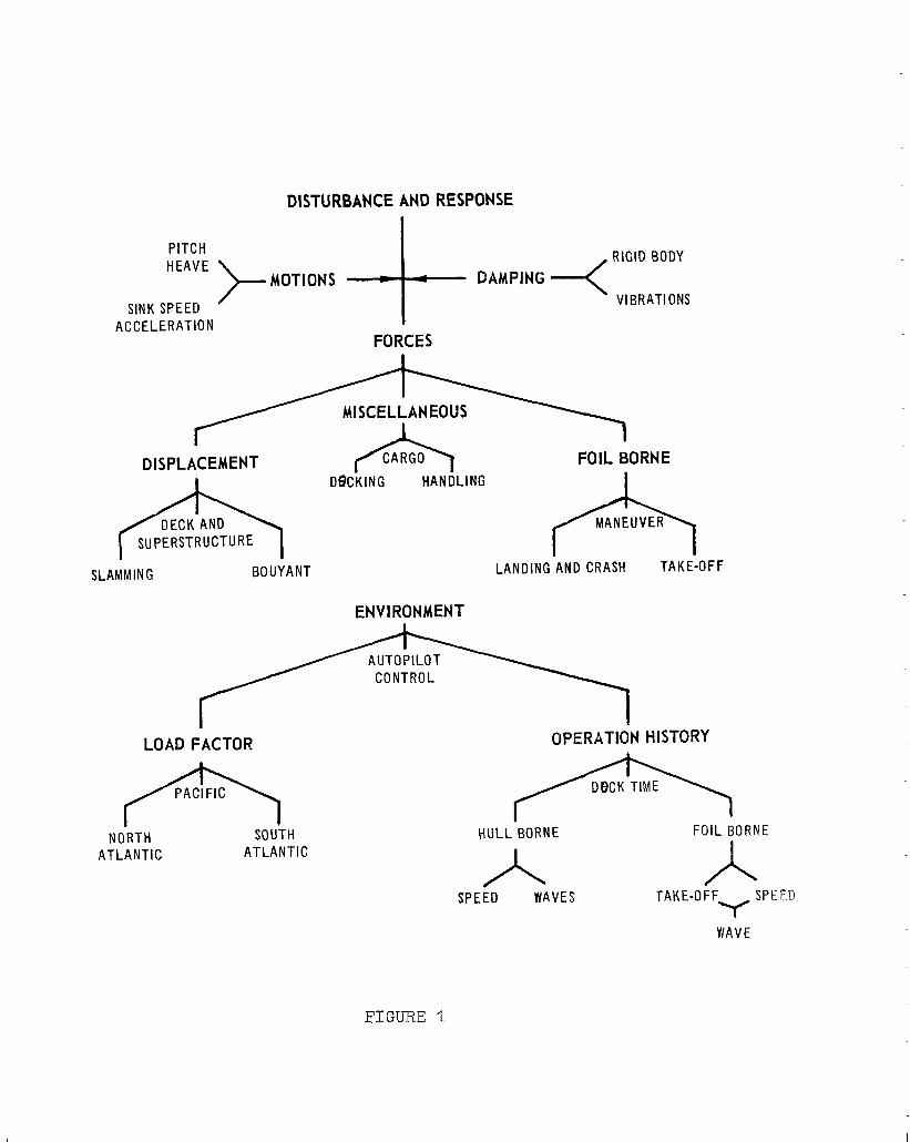
TEST PROGRAMS
There is an urgent need to obtain ship
performance and enviro~snent data to check assumptions made in design and needed in theo1~2tisal procedures,
Figure 1, gives "the major areas involved, The test
program has to include comprehensive data ccrrelating loads and craft motiorz2 with a pa22ticular sea state and aLso long term accumulated information on operational histories to establish env%ronment factors,
An example of ZLoadfng assumption made and
tc be checked is frequency and steepness OS waves and the direction of relat%ve ship course,which strongly inf%uenses the critical landing loads at high speed, A rational design needs to establish the number and type cf such loads expected during the I%fetime of ships
to determine proper fatigue factors, Further assumptions
a.re the point. of Empac', * during, landing and usual landing
t.ime ad speeds ta determirke the number of impacts,
There are or will be six hydrofoi% boats or ships which merl.*, consideration for use in program
to get the desired test information. These are :
1, 0 SEA LEGS, a 28-foot sd.xne:rged foil test craft
20 PCH, a IlO-fact subme:rged fofbl WSW ship
3. FRESH-l, a SO-%sc?t submerged foil supercavitating
expe,rimental boat, a 0 AGEH, a ZOO-foe'& submerged fo5.1, experimenta
ship,
"JO LCVP (higk,ZLander) 3 a 38-feet: surface-piercing foil boat,
6, DENISON, a lOO-foot,, eontroLe~~, surface piercing
roia boat 0
Some tests have 'been made 0% the stresses in the crai.f'c- huLS. and struts and pressure data on the SEA
E;EGS o 15" good wave heights and h.rlL clearance data was or" can be obtai.ned, s3me ,reI.ation betweefi craft vertical mo%fsn and foS% stress dynamic factors for an approximate wave height may be deter9Wr32d. This data would be of considerab3.e help to des;fgner in estabPishfng strut Pengths,
SEA LEGS tests could also help jG.0 obtain verification of strut forces and moments during tuPn%ngj especiallly in non-steady state c.ondltions and in waves as compared to calm water conditions used In design caEculat%ons, IIf landing ve%oc.ities can he obtained in tests, with associated h,unEl impact on pressuses and dist,ributions, a check of hull, pressure pred%cti.on procedure may be possible, Vibration hnfoxmation on thl.s Graft with the type of installX.ed machhery and PoL9 s~~pports is not representa-
tive of u, so Navy pmctice and is therefore of only academic interest.
The PCH is an operational ship, built for a
specifl,c operational ASW requirement \7 However, a
limited test. evaluation period has been assigned for
it0 The presently planned instrumented program should
give much useful data on the Disturbance and Response
questions as listed by Figure I., However, there is
some doubt on the avaIlabiLity of stress instrumenta-
tion and more pressure gages than now planned would
be needed to obtain complete bow pressure distributions,
A fulather automatic recording program should
be prepared for the ship to obtain a sampLe history of
operational use loading oy1 factors listed under
P’Envi.ronment’9 in Fi,gure 1, witlh a few key response measure-
ments (as done for alI modern ai,rpl.anes). In any event,
sspecial. note should be made on the influence and adjust-
ment. of the autopilot on the resultant. recorded data.
The AGEK experimental shi~p construction is
start,.ing O This ship is to be used t.o evaILuat,e the benefit
of hydrofoils for tasks to be determined, At the present
t I.me ,3 Ghere does not appear to be any USN program to
obt.ain a record of hull a& foil performance during this
pcri,od or during ix?itial. tests, A program similar to the
$CH program3 but pknned specifically for particular data
such as needed in desi.g:Y; an,d pY”oposed by report, reference
l,9 has to be establi,shed, This program planning should
be completed at. the earli.est time so as to permit an
orderly planning and installation of test instrumentation
on the ship while it is being b,uilt.
The FRESH-L is a test craft for evaluation of
supercavitating hydrofoi,i configurations O The equipment
on this craft includes a very extensive recording appara-
tus for h,ydrodynami~c and st.ruckural t.ests O The foils
are support.ed by special balances to permit measuring
forces and moments on the struts, However, to date,
there does not. appear Co be any planned program to
utilize thi,s craft for obtaining st.ruct+ural dat.a, The craft is being checked-o,llt with cambered, parabolic,
foils 0 The Grumman Aircraft Company is building a set
of supescavitatin g f0il.s for installation on this craft.
It is understood t.hat the Lift control will be by foil
rotati,on about a strut pivot,
Pls craft could be used in present vibration
program to eval.uar,e the performance of supercavitating
foils by investigating possible flutter occurrence as
from torsi.on and hinge pi,~ suppoaat desi.gn. Further
problems in fatigue may arise due to the relatively
flexible shape of foi.1 and- the possible cavity instability
at lower speeds i.r! waves,
The LCVP has fcur surface piercing foi.ls, design-
ed to high stlaess levels, These foils are scaled-up
versions of the YlXigh-~pos:k~t~ Ii type previously tested by
the David Taylor Mode.1 Basin.. The tests of this boatRs
foils wou.1.d provide useful, data to check, scale effects,
dyn.amic factors on foi.1 I.oad 1~. waves, and fatigue
property of the alumLnum foil msteria.l,
The Maritime Admi.nistrati.on had an extensive
test and evaluation progr;am @SP the BENISON. This program
and results should be monitored to check any data which
would be useful to the desi,gl^;ep.
Performance (Hull) -_
There are some basic criteria on the selection
of hydrofoi.l, ship design which rec,lLaires a compromise between
st~ructural and hydrodynamic aspects,
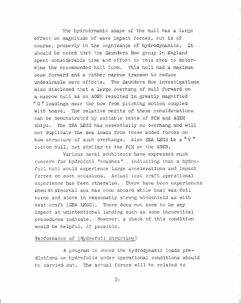
The hydrodynamic shape of the hull has a large
effect on magnitude of wave impact forces, but is of
course 9 properly in the cognUance of hydrodynamics, It
should be noted that the Saunders Roe group in England
spent considerable time and effort in this area to det.er-
mine the recommended hul.1 form. This hull, had a maximum
beam forward and a rather narrow transom to reduce
undesirable wave effects, The Saunders Roe investigations
also disclosed that a large overhang of hull forward on
a narrow hull as on AGEH resulted En greatly magnified
“G” loadings near the bow from pitching motion coupled
with heave. The relative meri.ts of these considerations
can, be demonstrated by suitable tests of PCH and AGEH
ships D The SEA LEGS has essentiall,y no overhang and wi1.l
not duplicate the sea loads from these added forces on
bow structure of such overhangs, Also SEA I.J%S 1s a “Y ”
bott,om huUI.1., not similar to the BCH or the AGEH.
Various naval architects have expressed much
concern for hydrofoil “crashes”’ .9 indicati,ng that a hydro-
foil. hull. would experience large accelerations and impact
forces on such. occasions, Actual test craft operatlonaa
experience has been otherwise O There have been experiences
whenanabnormal sea has come aboard while boat was foil
borne and stove in reasonably strong wi.ndshield as wi.th
test craft (SEA I;EGtS). There does not seem to be any
impact at unintentional Landing such as some theoretical
procedures indicate, HoweverS a check: of this condition
would be helpful, if possible,
Performance of (Rydrofo1.l. Structure)
A program to check the hydrodynamic loads pre-
dictions on hydrofoils under operat‘ional, condbtions should
be carried out, The actual. forces wi,ll be related to
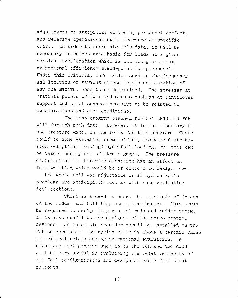
adjustments of autopilots conT.rols, personnel. comfort,
and relative operational hull clearance of specific
craft, I,n order to correlate this data, it will1 be
necessary to select some basis for loads at a given vertical acceleration which Is not too great from
operational efficiency stand-point for personnel.
Under this criteria, information such as the frequency and location of various stress levels and duration of
any one maximum need to be determined, The stresses at critical points of foil and struts such as at cantilever support and s'crut connections have to be related to
accelerations and wave conditions,
The test program planned for SEA LEGS and PCH will furnish such data, However, it Is not necessary to use pressure gages in the foils for this program. There could be some varfat..ion from uniform,P spanwise distribu-
tion (el,iptical loading) hydrofoi.l. loading;, but this can
be determined by use of strain gages, The pressure distribution in chordwise direction has an effect on
foil twisting which wouid be of concern in design wl-.en
the whole foil was adjustable or if hydroelastic
problems are ant.lcipated such as with supercavitating
foil sections,
There .is a need to check t.he magnitude of forces on the rudder and foi,l f".lap control mechanism. This would be required to design f.l_ap control. rods and rudder stock,
It is also useful to the designer of the servo control
devices, An automatic recorder should be installed on the
PCH to accumulate t.he cyclles of loads above a certain value
at critical. pcints during operational evaluation, A
structure test program such as on the PCH and Lhe AGEH
will be very useful in evaluating the relative merits of
the foil configuratlons and design of basic foil strut
supports,
16

MATEREALS
A review is to be conducted on the fabrication
and performance of the hul.l and foil structures of
hydrofoil cl?aft 0 This investigation is to determine what t;he permissible stresses are and the Limits which
fabrication problems impose on the designers freedom
in select.ing materials, IJnder certain conditions, as in the installation of transmission and foil connections,
optimum structure is not feasible. The problems of
surface protection and ga1vanj.c interaction with install-
ed equipment in huEl is also more easily determined by
inspecting and monitoring performances on the operational
ships,
Principle objectives are CO be:
1, CompiLe data on use of any problems in use of
aluminum and other materials,
2, Prepare comparison of aluminum with alternate
possi.bi.1,1,ti,es such as g.l.ass reinforced plastic or
titanium,
30 Specify acceptable values of stress to be used
for recommended material.,
Hydrofoil Construct3,on
The structural requisements for material fncrease
with both size and speed, Use of" aluminum appears to be
acceptable for boats up to about .I5 tons and 37 feet in
length, Larger craft require material of higher stress
levels and st,:iffness r,han.prov-l..ded by al.loys of aluminum
thaO can be immersed in sa1.t watePO High strength steels and certain titanium alloys have possible use provided
fabricat.ion techniques are developed for them,
J-7
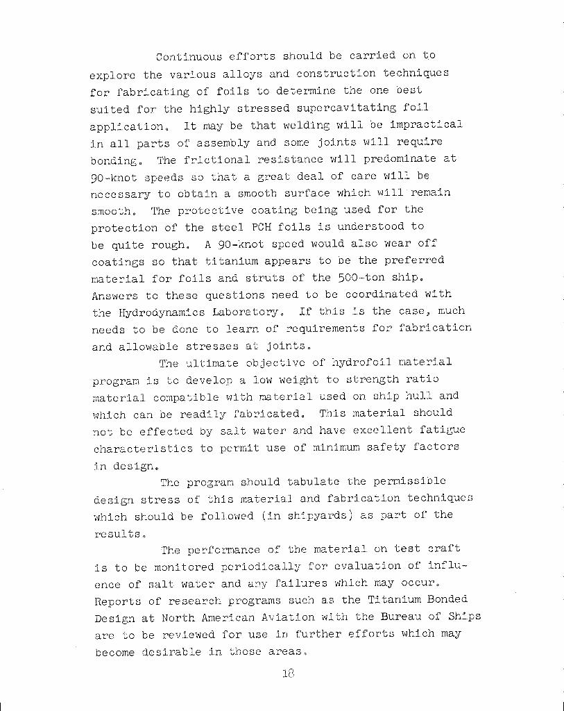
Continuous efforts should be carried on to
explore the varli,ous all.oys and construction techniques
for fabricating of foils to determine the one best
suited for the highly stressed supercavitating foil
application, Et may be that welding will be impractical
in all parts of assembly and some joints will require
bonding, The frictionall. resistance will predominate at
go-knot speeds so t:hat a great deal of care will. be
necessary to obtain a smooth su,rface which will remain
smooth, The protective coating being used for the
protection of the steel NH foils is understood to
be quite rough, A go-knot speed would also wear off
coatings so that titanium appears to be the preferred
material for foils and struts of the 500-ton ship,
Answers to these questions need to be coordinated with
the Hydrodynamics Laboratory, I,f this is the case9 much
needs to be done to learn of requirements for fabrication
and allowa'ble stresses at Joints, The ultimate obJectfve of hydrofoil material
program is to develop a low weight to strength ratio
material compatible with material used on ship hull and
which can be readily fabricated, This material should
not be effected by salt water and have excelllent fatigue
characteristics to permit use of minimum safety factors
in design, The program should tabulate the permissi,ble
design stress of this mater%al and fabrication techniques
which should be foll,owed (in shipyards) as part of the
resul.ts, The performance of the material, on test craft
is to be monit.ored periodically for evaluation of influ-
ence of salt water and any failures which may occur,
Reports of research programs such as the Titanium Bonded
Design at North Ameri,can Aviation with the Bureau of Ships
are to be reviewed for use in @u:rther efforts whi.ch may
become desirable hn those areas.
REFERENCES
1. Martin Company, Hydrofoil Craft Structural Design
Study I CONFIDENTIAL
2, Stevehs, Banko, and Arrone, Bureau of Ships,
Structural Load Criteria for Hydrofoil Ships
3. Merritt, R. G,, Boeing Airplane Co., Structural
Design for Safety in High Speed Ships 4. DTMB Technical Note SML-760-17, Progress Report No. 1, An Investigation of'loadings Experienced by
Hydrofoil Craft. Progress Report No. 1
DTlYB Technical Note SML-760-17
Prepared by
Approved by R Pete-r BeLerl, USN
DISTURBANCE AND RESPONSE
PITCH HEAVE
ACCELERATION FORCES
;
DISPLACEMENT CARGO FOIL BORNE
p&&q DeCK’NG HANDL’NG &*oFF
SLAMMING BOUYANT LANDING AND CRASH
ENVIRONMENT
LOAD FACTOR OPERATION HISTORY
(5Gky IBORNE
NORTH SOUTH HULLBORNE
ATLANTIC ATLANTIC
A A SPEED WAVES TAKE-OFF
“f SPEED
WAVE