Embed Size (px)
Citation preview
Proceedings IRF2018: 6th International Conference Integrity-Reliability-Failure
Lisbon/Portugal 22-26 July 2018. Editors J.F. Silva Gomes and S.A. Meguid
Publ. INEGI/FEUP (2018); ISBN: 978-989-20-8313-1
-1011-
PAPER REF: 7237
STRUCTURAL VALIDATION OF INTRAMEDULLARY NAILS: FROM
EXPERIMENTATION TO VIRTUAL TESTING
D. Croccolo, M. De Agostinis(*)
, S. Fini, S. Funaioli, G. Olmi, F. Robusto
Department of Industrial Engineering, University of Bologna, Italy (*)
Email: [email protected]
ABSTRACT
Closed intramedullary nailing has become the “gold standard” in the treatment of displaced
fractures of the tibial shaft. The material of choice for the manufacturing of intramedullary
nails is Ti-alloy, while the structural performance requested to these components is steadily
growing. Validation procedures pertaining to these components comprehend both
compression and torsion tests. Finite element analysis could help shrinking down the time
required for new product development, as fewer full scale experimental tests would be needed
in the early design stages. In order for numerical models to be representative of the actual test,
a number of parameters has to be accurately chosen: particularly, contact modeling must be
fine-tuned based on experimental data. This contribution provides guidelines for the correct
contact settings to use, referring to the Ansys software.
Keywords: intramedullary nail, FEA, contact, joint.
INTRODUCTION
Closed intramedullary nailing has become increasingly popular in the treatment of displaced
fractures of the tibial shaft [Leung et al., 2006]. Due to their comparatively compact
dimensions, intramedullary nails require high performance materials in terms of mechanical
properties. Both titanium alloys and stainless steels have been used for the construction of
such devices, even if, there has recently been evidence of better performance of titanium alloy
nails, versus stainless-steel counterparts [Riemer et al., 1995]. In accordance with relevant
international standards, two tests are required for the validation of a new nail: a static four-
point bending test and a torsional test. Moreover, manufacturers usually run internal
validation tests also for the loading case of axial compression. The development of an
accurate finite element analysis would allow performing a quick identification of the most
critical combination of nail size and testing conditions. This would in turn mean to shrink
down the development time needed for the release of new products. Besides adequate
modeling of the material response, a proper contact modeling strategy is critical in order for
the numerical model to accurately represent the experimental test. The present contribution
focuses on non-linear contacts and their formulation: although some authors provided
contributions describing finite element models of intramedullary nails [Simpson et al., 2008],
none focused on how to properly choose the contact settings between the nail and the fixtures.
This contribution aims at filling such a lack of information. Although the data provided in the
present contribution is referred to the Ansys software, it can easily be extended to other
commercial FEA softwares.
Symp-06: Fastening and Joining Technology
-1012-
MATERIALS AND METHODS
The intramedullary nail object of the present investigation is made of Ti6Al4V ELI [ASTM,
2013] according to the general dimensions reported in Figure 1. The test fixtures used in the
experimentation, are manufactured from AISI 304 [EN, 2014]. The mechanical properties of
the materials are reported in Table 1.
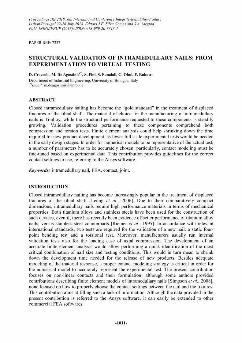
Fig. 1 - Geometry of the tibial intramedullary nail object of this study
Table 1 - Mechanical properties of the materials
Torsional tests have been performed on a “MTS 858 mini bionix II” axial and torsional
servohydraulic machine. Three repetitions for each of the following constraint configurations
were executed, using nominally identical specimens: (i) proximal pins and distal pins
(PP_DP), (ii) proximal pins and distal screws (PP_DS), (iii) proximal screws and distal pins
(PS_DP), (iv) proximal screws and distal screws (PS_DS). The rationale behind this different
configurations is that, during testing, the screws (which are actually used to secure the nail to
the bone) may be conveniently replaced by parallel pins. Then it is interesting to check
whether the simplifications adopted during testing entail significant differences in terms of
overall stiffness with respect to the actual application.
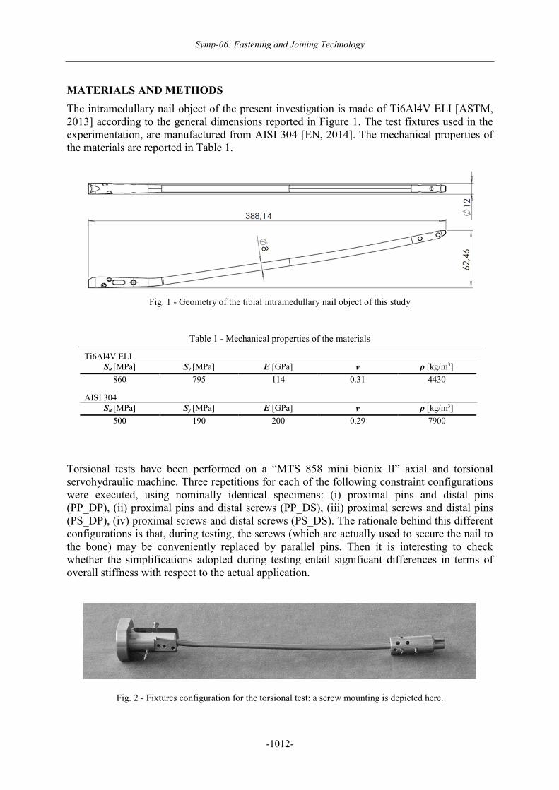
Fig. 2 - Fixtures configuration for the torsional test: a screw mounting is depicted here.
Ti6Al4V ELI
Su [MPa] Sy [MPa] E [GPa] ν ρ [kg/m3]
860 795 114 0.31 4430
AISI 304
Su [MPa] Sy [MPa] E [GPa] ν ρ [kg/m3]
500 190 200 0.29 7900
Proceedings IRF2018: 6th International Conference Integrity-Reliability-Failure
-1013-
Fig. 3 - Proximal constraints - Screws (left) and pins (right)
A screw mounting of the nail can be seen in Figure 2, whereas the difference between screw
and pin mounting at the distal end of the nail can be appreciated by looking at Figure 3.
In order to avoid a statically indeterminate system, the distal end has been connected to the
actuator by a double universal joint. The tests have been executed under displacement control,
by imposing a rotation equal to ϴ = 5 ° at a constant angular velocity of ω = 5 °/min. Results
in terms of torsional moment Mt at the fixed end have been measured.
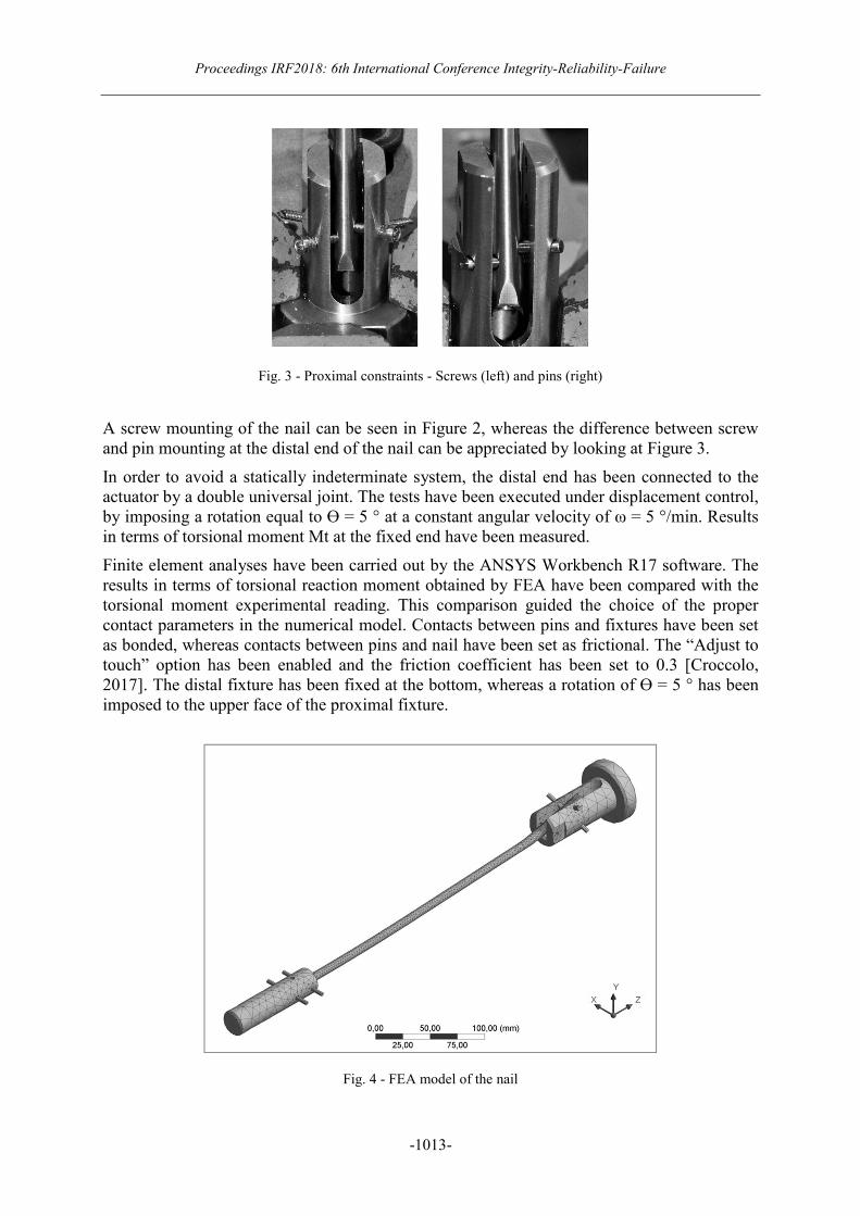
Finite element analyses have been carried out by the ANSYS Workbench R17 software. The
results in terms of torsional reaction moment obtained by FEA have been compared with the
torsional moment experimental reading. This comparison guided the choice of the proper
contact parameters in the numerical model. Contacts between pins and fixtures have been set
as bonded, whereas contacts between pins and nail have been set as frictional. The “Adjust to
touch” option has been enabled and the friction coefficient has been set to 0.3 [Croccolo,
2017]. The distal fixture has been fixed at the bottom, whereas a rotation of ϴ = 5 ° has been
imposed to the upper face of the proximal fixture.
Fig. 4 - FEA model of the nail
Symp-06: Fastening and Joining Technology
-1014-
Frictional contacts have been detected on Gauss’ points. The mesh has a general element size
equal to 3 mm: a refinement in the contact regions has been applied, with an element size of 1
mm. The result is a total element count of 49,415 SOLID186 and SOLID187, for a total
number of nodes equal to 83,697: the meshed geometry is shown in Figure 4. By tuning the
normal stiffness factor of the frictional contacts, a comparison with the experimental results
has been carried out.
RESULTS AND CONCLUSIONS
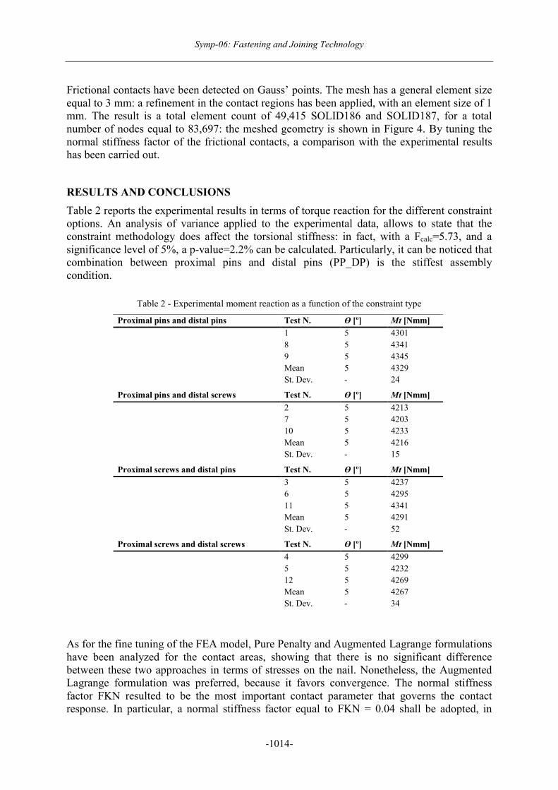
Table 2 reports the experimental results in terms of torque reaction for the different constraint
options. An analysis of variance applied to the experimental data, allows to state that the
constraint methodology does affect the torsional stiffness: in fact, with a Fcalc=5.73, and a
significance level of 5%, a p-value=2.2% can be calculated. Particularly, it can be noticed that
combination between proximal pins and distal pins (PP_DP) is the stiffest assembly
condition.
Table 2 - Experimental moment reaction as a function of the constraint type
As for the fine tuning of the FEA model, Pure Penalty and Augmented Lagrange formulations
have been analyzed for the contact areas, showing that there is no significant difference
between these two approaches in terms of stresses on the nail. Nonetheless, the Augmented
Lagrange formulation was preferred, because it favors convergence. The normal stiffness
factor FKN resulted to be the most important contact parameter that governs the contact
response. In particular, a normal stiffness factor equal to FKN = 0.04 shall be adopted, in
Proximal pins and distal pins Test N. ϴ [º] Mt [Nmm]
1 5 4301
8 5 4341
9 5 4345
Mean 5 4329
St. Dev. - 24
Proximal pins and distal screws Test N. ϴ [º] Mt [Nmm]
2 5 4213
7 5 4203
10 5 4233
Mean 5 4216
St. Dev. - 15
Proximal screws and distal pins Test N. ϴ [º] Mt [Nmm]
3 5 4237
6 5 4295
11 5 4341
Mean 5 4291
St. Dev. - 52
Proximal screws and distal screws Test N. ϴ [º] Mt [Nmm]
4 5 4299
5 5 4232
12 5 4269
Mean 5 4267
St. Dev. - 34
Proceedings IRF2018: 6th International Conference Integrity-Reliability-Failure
-1015-
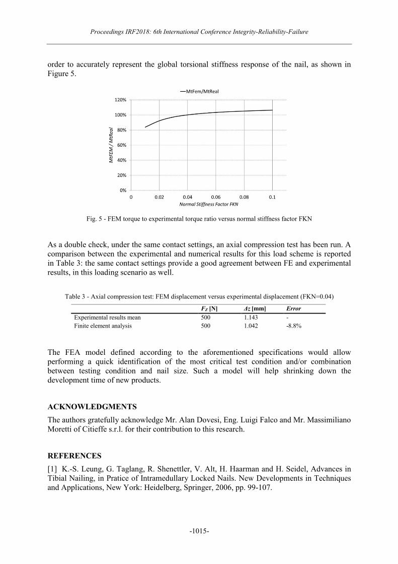
order to accurately represent the global torsional stiffness response of the nail, as shown in
Figure 5.
Fig. 5 - FEM torque to experimental torque ratio versus normal stiffness factor FKN
As a double check, under the same contact settings, an axial compression test has been run. A
comparison between the experimental and numerical results for this load scheme is reported
in Table 3: the same contact settings provide a good agreement between FE and experimental
results, in this loading scenario as well.
Table 3 - Axial compression test: FEM displacement versus experimental displacement (FKN=0.04)
The FEA model defined according to the aforementioned specifications would allow
performing a quick identification of the most critical test condition and/or combination
between testing condition and nail size. Such a model will help shrinking down the
development time of new products.
ACKNOWLEDGMENTS
The authors gratefully acknowledge Mr. Alan Dovesi, Eng. Luigi Falco and Mr. Massimiliano
Moretti of Citieffe s.r.l. for their contribution to this research.
REFERENCES
[1] K.-S. Leung, G. Taglang, R. Shenettler, V. Alt, H. Haarman and H. Seidel, Advances in
Tibial Nailing, in Pratice of Intramedullary Locked Nails. New Developments in Techniques
and Applications, New York: Heidelberg, Springer, 2006, pp. 99-107.
FZ [N] ∆z [mm] Error
Experimental results mean 500 1.143 -
Finite element analysis 500 1.042 -8.8%
Symp-06: Fastening and Joining Technology
-1016-
[2] B. Riemer, D. DiChristina, C. A, S. Sagiv, S. B. C. Butterfield, J. Lucke and J. Schlosser,
Nonreamed nailing of tibial diaphyseal fractures in blunt polytrauma patients, J. Orthop
Trauma, vol. 9, no. 1, pp. 66-75, 1995.
[3] D. Simpson, C. Brown, A. Yettram, P. Procter and G. Andrew, Finite element analysis of
intramedullary devices: The effect of the gap between the implant and the bone, Proceedings
of the Institution of Mechanical Engineers, Part H: Journal of Engineering in Medicine, vol.
222, no. 3, pp. 333-345, 2008.
[4] ASTM F136-13, Standard Specification for Wrought Titanium-6Aluminum-4Vanadium
ELI (Extra Low Interstitial) Alloy for Surgical Implant Applications (UNS R56401), 2013.
[5] EN 10088-1, Stainless steels - Part 1: List of stainless steels, 2014.
[6] D. Croccolo, M. De Agostinis, S. Fini and G. Olmi, "Tribological properties of bolts
depending on different screw coatings and lubrications: An experimental study," Tribology
International, vol. 107, pp. 199-205, 2017.

![Experimental study of friction in aluminium bolted joints Experimental study of friction in aluminium bolted joints D . Croccolo 1,a, M . De Agostinis 1, N . ... Motosh [7] and VDI2230](https://img.pdfslide.net/doc/110x75/5b9967e509d3f29c338c3f23/experimental-study-of-friction-in-aluminium-bolted-joints-experimental-study-of.jpg)


![FatigueCrack GrowthBehaviourof Nitridedand Shot PeenedSpecimens · In [Croccolo, and etc., 2002] the fatigue strength of a shot-peened nitrided low-alloy steel is investigated and](https://img.pdfslide.net/doc/110x75/5c66e36409d3f2e33b8cc1a3/fatiguecrack-growthbehaviourof-nitridedand-shot-in-croccolo-and-etc-2002.jpg)


![DETECTION OF DEFECTS IN COMPOSITE HELMETS USING …irf/Proceedings_IRF2018/data/papers/7143.pdf[4] Wang Y.M., Wu Q. Experimental Detection of Composite Delamination Damage based on](https://img.pdfslide.net/doc/110x75/5f0341257e708231d4084d98/detection-of-defects-in-composite-helmets-using-irfproceedingsirf2018datapapers7143pdf.jpg)