Embed Size (px)
Citation preview
StructuralWelding CodeSeismicSupplement
—
AWS D1.8/D1.8M:2016An American National Standard
AWS D1.8/D1.8M:2016An American National Standard
Approved by theAmerican National Standards Institute
August 3, 2016
Structural Welding Code—
Seismic Supplement
3rd Edition
Supersedes AWS D1.8/D1.8M:2009
Prepared by theAmerican Welding Society (AWS) D1 Committee on Structural Welding
Under the Direction of theAWS Technical Activities Committee
Approved by theAWS Board of Directors
Abstract
This code supplements the requirements of AWS D1.1/D1.1M, Structural Welding Code—Steel. This code is intendedto be applicable to welded joints in Seismic Force Resisting Systems designed in accordance with the AISC SeismicProvisions. Clauses 1–7 constitute a body of rules for the regulation of welding in Seismic Force Resisting Systems.There are seven mandatory annexes in this code. A commentary of the code is included with the document.
ii
AWS D1.8/D1.8M:2016
ISBN: 978-0-87171-894-5© 2016 by American Welding Society
All rights reservedPrinted in the United States of America
Photocopy Rights. No portion of this standard may be reproduced, stored in a retrieval system, or transmitted in anyform, including mechanical, photocopying, recording, or otherwise, without the prior written permission of the copyrightowner.
Authorization to photocopy items for internal, personal, or educational classroom use only or the internal, personal, oreducational classroom use only of specific clients is granted by the American Welding Society provided that the appropri-ate fee is paid to the Copyright Clearance Center, 222 Rosewood Drive, Danvers, MA 01923, tel: (978) 750-8400; Internet:<www.copyright.com>.
iii
AWS D1.8/D1.8M:2016
Statement on the Use of American Welding Society Standards
All standards (codes, specifications, recommended practices, methods, classifications, and guides) of the AmericanWelding Society (AWS) are voluntary consensus standards that have been developed in accordance with the rules of theAmerican National Standards Institute (ANSI). When AWS American National Standards are either incorporated in, ormade part of, documents that are included in federal or state laws and regulations, or the regulations of other governmen-tal bodies, their provisions carry the full legal authority of the statute. In such cases, any changes in those AWS stan-dards must be approved by the governmental body having statutory jurisdiction before they can become a part of thoselaws and regulations. In all cases, these standards carry the full legal authority of the contract or other document thatinvokes the AWS standards. Where this contractual relationship exists, changes in or deviations from requirements of anAWS standard must be by agreement between the contracting parties.
AWS American National Standards are developed through a consensus standards development process that bringstogether volunteers representing varied viewpoints and interests to achieve consensus. While AWS administers the pro-cess and establishes rules to promote fairness in the development of consensus, it does not independently test, evaluate,or verify the accuracy of any information or the soundness of any judgments contained in its standards.
AWS disclaims liability for any injury to persons or to property, or other damages of any nature whatsoever, whetherspecial, indirect, consequential, or compensatory, directly or indirectly resulting from the publication, use of, or relianceon this standard. AWS also makes no guarantee or warranty as to the accuracy or completeness of any information pub-lished herein.
In issuing and making this standard available, AWS is neither undertaking to render professional or other services for oron behalf of any person or entity, nor is AWS undertaking to perform any duty owed by any person or entity to someoneelse. Anyone using these documents should rely on his or her own independent judgment or, as appropriate, seek theadvice of a competent professional in determining the exercise of reasonable care in any given circumstances. It isassumed that the use of this standard and its provisions is entrusted to appropriately qualified and competent personnel.
This standard may be superseded by new editions. This standard may also be corrected through publication of amend-ments or errata, or supplemented by publication of addenda. Information on the latest editions of AWS standards includ-ing amendments, errata, and addenda is posted on the AWS web page (www.aws.org). Users should ensure that theyhave the latest edition, amendments, errata, and addenda.
Publication of this standard does not authorize infringement of any patent or trade name. Users of this standard acceptany and all liabilities for infringement of any patent or trade name items. AWS disclaims liability for the infringement ofany patent or product trade name resulting from the use of this standard. AWS does not monitor, police, or enforce com-pliance with this standard, nor does it have the power to do so.
Official interpretations of any of the technical requirements of this standard may only be obtained by sending a request,in writing, to the appropriate technical committee. Such requests should be addressed to the American Welding Society,Attention: Managing Director, Technical Services Division, 8669 NW 36 St, # 130, Miami, FL 33166 (see Annex I).With regard to technical inquiries made concerning AWS standards, oral opinions on AWS standards may be rendered.These opinions are offered solely as a convenience to users of this standard, and they do not constitute professionaladvice. Such opinions represent only the personal opinions of the particular individuals giving them. These individualsdo not speak on behalf of AWS, nor do these oral opinions constitute official or unofficial opinions or interpretations ofAWS. In addition, oral opinions are informal and should not be used as a substitute for an official interpretation.
This standard is subject to revision at any time by the AWS D1 Committee on Structural Welding. It must be reviewedevery five years, and if not revised, it must be either reaffirmed or withdrawn. Comments (recommendations, additions,or deletions) and any pertinent data that may be of use in improving this standard are requested and should be addressedto AWS Headquarters. Such comments will receive careful consideration by the AWS D1 Committee on StructuralWelding and the author of the comments will be informed of the Committee’s response to the comments. Guests areinvited to attend all meetings of the AWS D1 Committee on Structural Welding to express their comments verbally. Pro-cedures for appeal of an adverse decision concerning all such comments are provided in the Rules of Operation of theTechnical Activities Committee. A copy of these Rules can be obtained from the American Welding Society, 8669 NW36 St, # 130, Miami, FL 33166.

This page is intentionally blank.
iv
AWS D1.8/D1.8M:2016
iv
v
AWS D1.8/D1.8M:2016
Personnel
AWS D1 Committee on Structural WeldingA.W. Sindel (Chair) GE Power-Steam Power Systems
T. L. Niemann (Vice Chair) Minnesota Department of TransportationR. D. Medlock (2nd Vice Chair) High Steel Structures, LLC
J. Molin (Secretary) American Welding SocietyF. G. Armao The Lincoln Electric Company
E. L. Bickford Acute Technological ServicesT. W. Burns Airgas
H. H. Campbell, III Pazuzu EngineeringR. D. Campbell Bechtel
R. B. Corbit CB&IM. A. Greico Massachusetts Department of TransportationJ. J. Kenney Shell International E&PJ. H. Kiefer ConocoPhillips (Retired)S. W. Kopp High Steel Structures, LLC
V. Kuruvilla Genesis Quality SystemsJ. Lawmon American Engineering and Manufacturing, Incorporated
N. S. Lindell VigorD. R. Luciani Canadian Welding Bureau
P. W. Marshall MHP Systems EngineeringM. J. Mayes Mayes Testing Engineers, A Terracon Company
D. L. McQuaid D. L. McQuaid & Associates, IncorporatedJ. Merrill Caltrop Corporation
D. K. Miller The Lincoln Electric CompanyJ. B. Pearson, Jr. LTK Engineering Services
D. C. Phillips Hobart Brothers CompanyD. D. Rager Rager Consulting, Incorporated
T. J. Schlafly AISCR. E. Shaw, Jr. Steel Structures Technology Center, Incorporated
R. W. Stieve Parsons CorporationM. M. Tayarani Pennoni
P. Torchio, III Williams Enterprises of Georgia, IncorporatedD. G. Yantz Canadian Welding Bureau
Advisors to the AWS D1 Committee on Structural Welding
W. G. Alexander WGAPEN. J. Altebrando STV, Incorporated
E. M. Beck AMECB. M. Butler Walt Disney World Company
G. L. Fox ConsultantH. E. Gilmer Tampa Tank—Florida Structural Steel
G. J. Hill G. J. Hill & AssociatesM. L. Hoitomt ConsultantC. W. Holmes Modjeski & Masters, Incorporated
G. S. Martin GE—Power
vi
AWS D1.8/D1.8M:2016
J. W. Post J. W. Post & Associates, IncorporatedK. K. Verma ConsultantB. D. Wright Advantage Aviation Technologies
AWS D1L Subcommittee on Seismic IssuesM. J. Mayes (Chair) Mayes Testing Engineers, A Terracon CompanyJ. Molin (Secretary) American Welding Society
S. E. Anderson HRV Conformance VerificationD. A. Koch Bechtel National, Incorporated
J. Malley Degenkold EngineersB. R. Manning Schuff Steel
D. W. Meyer ESAB Welding & Cutting ProductsD. K. Miller The Lincoln Electric Company
D. C. Phillips Hobart Brothers CompanyT. J. Schlafly AISC
R. E. Shaw, Jr. Steel Structures Technology Center, IncorporatedR. H. Tide Wiss Janney Elstner Associates
Advisors to the D1L Subcommittee on Seismic Issues
N. J. Altebrando STV, IncorporatedT. Green WJE
R. Hamburger Simpson Gumpertz & HegerD. K. Panda TMK IPSCO
J. W. Post J. W. Post & Associates, IncorporatedD. D. Rager Rager Consulting, Incorporated
D. Rees-Evans Steel Dynamics
Advisors to the AWS D1 Committee on Structural Welding (Continued)
vii
AWS D1.8/D1.8M:2016
Foreword
This foreword is not part of this standard but is included for informational purposes only.
This is the third edition of the AWS D1.8/D1.8M, Structural Welding Code—Seismic Supplement.
Editorial and technical revisions from the previous edition are indicated by underlining text. Changes in tables andfigures have a single, vertical line in the margin. The following is a list of the most significant revisions from the 2009edition:
Clause 6 entitled “Fabrication” has been reorganized for user read ability. This reorganization has required renumberingof the majority of the subclauses within Clause 6 as well as extensive reference changes throughout this supplement.
Clause 3: Doubler is now defined.
Clause 4.3: A new clause that defines when joint details for doublers are suitable for use in a prequalified WPS. Theclause also states when macroetch tests are required and acceptance criteria for macroetch specimens.
Figure 4.3: A new figure that depicts the doubler to column flange joint detail was added.
5.1.1(1): The words “complete joint penetration groove weld” were added for clarification.
5.1.1(3): The words “in the groove” were added for clarification.
5.1.2: The words “in the flat position” were added for clarification.
6.2.1(2): Solid GMAW electrodes classified in AWS A5.18/A5.18M or AWS A5.28/A5.28M as ER70 or ER80 [ER48or ER55] tensile strength have been added to the list of exempt filler metals.
6.2.1(4): AWS A5.29/5.29M E70 or E80 [E49 or E55] low alloy FCAW electrodes have been added to the list of exemptfiller metals.
6.2.1(5): A new subclause added to the list of exempt filler metals for AWS A5.36/A5.36M:2012, Specification forCarbon and Low-Alloy Steel Flux Cored Electrodes for Flux Cored Arc Welding and Metal Cored Electrodes for GasMetal Arc Welding.
6.2.1(6): A new subclause was added to the list of exempt filler metals regarding E90 [E62] Low Alloy SMAW, FCAW,GMAW composite (metal cored) and solid electrodes, and low alloy electrode/flux SAW combinations that have beenoptionally tested by the filler metal manufacturer in accordance with AWS A5.20/A5.20M:2005 Clause 17.
6.2.2: Additional parameters were added to the Lowest Anticipated Service Temperature for 70 ksi, 80 ksi, and 90 ksi[490 MPa, 550 MPa, and 620 MPa] filler metals.
6.3.1.3: ER70 and ER80 [ER48 and ER55] GMAW solid electrodes were added to the list of exceptions.
6.8.1(2): For carbon steel FCAW electrodes classified with the supplemental designator “-D” the heat input range pre-scribed in Clause 17 of AWS A5.20/A5.20M:2005 was added to the list of acceptable heat input limits.
6.8.1(3): The tensile strength was clarified.
6.8.1(4): For low alloy electrodes classified as 90 ksi [620 MPa] tensile strength, SMAW, GMAW metal core and solidelectrodes, FCAW electrodes, and SAW electrode/flux combinations were added to the list of acceptable heat input limits.
6.8.1(5): For AWS A5.36/A5.36M:2012 Clause 16 for carbon and low alloy steel FCAW and GMAW-metal core elec-trodes classified with the supplemental designator “-D” was added to the list of acceptable heat input limits along with anote offering further explanation.
viii
AWS D1.8/D1.8M:2016
6.12.3: A new clause regarding tack welds that attach steel backing in the protected zone.
6.14: The words “weld root” were replaced with back weld for clarification.
6.18.6: A new clause regarding the repair of mislocated holes.
6.18.7: A new clause regarding the repair of mislocated stud welds.
6.18.8: A new clause regarding the repair of mislocated screws and shot pins.
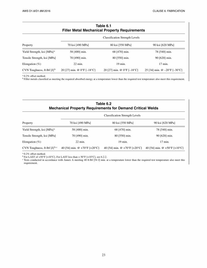
Table 6.1: The addition of parameters for 90 ksi [620 MPa] filler metal and a new footnote regarding the offset method.
Table 6.2: The addition of parameters for 90 ksi [620 MPa] filler metal. New footnotes regarding the offset method andadditional parameters for LAST.
Table 6.3: AWS A5.36/A5.36M:2012 was added to the table.
Figure 6.1(B): New text depicting the figure was added for clarification.
A4: New text regarding the qualification of E90 [E62] filler metals.
Table A.2: Electrode Classification Strength E90 [E62] was added to the table.
B3: New text regarding the evaluation of E90 [E62] filler metal combinations.
B7: Additional text regarding CVN toughness for welds using 70 ksi, 80 ksi, and 90 ksi [490 MPa, 550 MPa, and 620 MPa].
E3.2: AWS A5.36/A5.36M:2012 Clause 15, Diffusible Hydrogen Test was added as an additional testing procedureoption for diffusible hydrogen levels.
G10: Subclause modified for clarification.
Background. Damage sustained by welded steel moment-frame buildings in the 1994 Northridge earthquake, andextensive research conducted by the FEMA/SAC program following that earthquake, demonstrated that in order toobtain adequate performance of welded steel structures under conditions of severe earthquake-induced inelastic strain-ing, additional controls on design, detailing, materials, workmanship, testing, and inspection are necessary. Thisresearch resulted in substantive changes to the AISC Seismic Provisions, which control the design of steel Seismic ForceResisting Systems (SFRS) designed to withstand severe inelastic straining as well as certain aspects of the materials anddetailing of these systems. The provisions contained in this standard complement the AISC Seismic Provisions and areintended to ensure that welded joints that are designed to undergo significant repetitive inelastic strains as a result ofearthquakes, or that are used to connect members designed to resist such inelastic strains, have adequate strength, notchtoughness, and integrity to perform as intended. This code, together with AWS D1.1/D1.1M, specifies the acceptablematerials, procedures, and workmanship for constructing welded joints in SFRS designed in accordance with the AISCSeismic Provisions as well as the procedures and acceptance criteria for quality control and quality assurance inspectionof welded joints in the SFRS. In some regions of the U.S., with low risk of intense earthquake shaking, building codespermit design of steel Seismic Force Resisting Systems that do not conform to the requirements of the AISC SeismicProvisions. The requirements of this code apply only to the SFRS in structures designed in accordance with the AISCSeismic Provisions and need not be applied to structures not designed to those provisions.
Commentary. The Commentary is nonmandatory and is intended only to provide insight, information, and provisionrationale.
Normative Annexes. These annexes address specific subjects in the code and their requirements are mandatory require-ments that supplement the code provisions.
Errata. All errata to a standard shall be published in the Welding Journal and posted on the AWS website(www.aws.org/standards/page/errata).
Suggestions. Comments and suggestions for the improvement of this standard are welcome. They should be sent to theSecretary, D1L Subcommittee on Seismic Provisions, American Welding Society, 8669 NW 36 St, # 130, Miami, FL33166.
ix
AWS D1.8/D1.8M:2016
Table of Contents
Page No.
Personnel ......................................................................................................................................................................vForeword .....................................................................................................................................................................viiList of Tables................................................................................................................................................................xiList of Figures.................................................................................................................................................................xi
1. General Requirements ........................................................................................................................................11.1 Scope.............................................................................................................................................................11.2 Standard Units of Measurement ...................................................................................................................11.3 Safety Precautions.........................................................................................................................................11.4 Responsibilities .............................................................................................................................................21.5 Limitations ....................................................................................................................................................31.6 Welding Symbols ..........................................................................................................................................3
2. Normative References .........................................................................................................................................5
3. Terms and Definitions .........................................................................................................................................7
4. Welded Connection Details.................................................................................................................................94.1 Corner Clips of Continuity Plates and Stiffeners..........................................................................................94.2 Transitions in Thicknesses and Widths.........................................................................................................94.3 Joint Details for Doublers .............................................................................................................................9
5. Welder Qualification .........................................................................................................................................135.1 Supplemental Welder Qualification Testing ...............................................................................................135.2 Welder Qualification Period........................................................................................................................135.3 Welder Performance Qualification Record Information.............................................................................13
6. Fabrication .........................................................................................................................................................15Part A—Filler Metal and Weld Metal..................................................................................................................156.1 Filler Metal and Weld Metal .......................................................................................................................15
Part B—Additional Requirements for Demand Critical Filler Metal and Weld Metal .......................................156.2 Heat Input Envelope....................................................................................................................................156.3 Production Lot Control ...............................................................................................................................166.4 FCAW Electrode Packaging, Storage, and Exposure .................................................................................17
Part C—Welding Procedure Specifications .........................................................................................................186.5 Welding Processes ......................................................................................................................................186.6 Welding Procedure Specifications (WPSs).................................................................................................186.7 Maximum Interpass Temperature ...............................................................................................................186.8 Heat Input ...................................................................................................................................................196.9 Bottom Flange Welding Sequence..............................................................................................................196.10 Welder Identification...................................................................................................................................19
Part D—Details ...................................................................................................................................................206.11 Weld Access Holes .....................................................................................................................................206.12 Tack Welding Requirements .......................................................................................................................206.13 Removal of Backing and Weld Root Treatment .........................................................................................216.14 Reinforcing Fillet Welds at Removed Weld Backing Locations ................................................................216.15 Fillet Welds at Left-In-Place Steel Backing................................................................................................21
x
Page No.
AWS D1.8/D1.8M:2016
6.16 Weld Tabs....................................................................................................................................................216.17 End Dams....................................................................................................................................................21
Part E—Protected Zone.......................................................................................................................................226.18 Protected Zone ............................................................................................................................................22
7. Inspection ...........................................................................................................................................................297.1 Inspection Task Assignment .......................................................................................................................297.2 Inspector Qualifications ..............................................................................................................................297.3 Quality Assurance Agency Written Practice ..............................................................................................307.4 Wide-Flange k-Area Inspection ..................................................................................................................307.5 Lamellar Tearing.........................................................................................................................................307.6 Beam Copes and Weld Access Holes .........................................................................................................307.7 Repaired Weld Access Holes in the Protected Zone...................................................................................307.8 NDT of Repaired Tab Removal Sites..........................................................................................................307.9 Magnetic Particle Testing Requirements ....................................................................................................307.10 Ultrasonic Testing .......................................................................................................................................30
Annex A (Normative)—WPS Heat Input Envelope Testing of Filler Metals for Demand Critical Welds ................33Annex B (Normative)—Intermix CVN Testing of Filler Metal Combinations (where one of the
filler metals is FCAW-S)......................................................................................................37Annex D (Normative)—Supplemental Welder Qualification for Restricted Access Welding...................................45Annex E (Normative)—Supplemental Testing for Extended Exposure Limits for FCAW Filler Metals ..................51Annex F (Normative)—Supplemental Ultrasonic Technician Qualification .............................................................53Annex G (Normative)—Supplemental Magnetic Particle Testing Procedures ..........................................................55Annex H (Normative)—Flaw Sizing by Ultrasonic Testing ......................................................................................59Annex I (Informative)—Requesting an Official Interpretation on an AWS Standard ...............................................61Annex J (Informative)—Informative References .......................................................................................................63
Commentary ...............................................................................................................................................................65Foreword.....................................................................................................................................................................67
Index .........................................................................................................................................................................113
List of AWS Documents on Structural Welding.......................................................................................................123
xi
AWS D1.8/D1.8M:2016
List of Tables
Table Page No.
6.1 Filler Metal Mechanical Property Requirements ........................................................................................236.2 Mechanical Property Requirements for Demand Critical Welds ................................................................236.3 Diffusible Hydrogen Testing Requirements ................................................................................................24A.1 Heat Input Envelope Testing—Heat Input, Preheat, and Interpass Temperatures.......................................35A.2 All Weld Metal Mechanical Properties; Yield Strength, Tensile Strength, Elongation, and CVN
Toughness Requirements.............................................................................................................................35B.1 Filler Metal Essential Variables—FCAW-S Substrate/Root .......................................................................39B.2 Filler Metal Essential Variables—FCAW-S Fill..........................................................................................39
CommentaryC-1.1 Removal of Tabs and Backing.....................................................................................................................73
List of Figures
Figure Page No.
4.1 Transition of Butt Joints in Parts of Unequal Thicknesses..........................................................................104.2 Transition of Butt Joints in Parts of Unequal Widths..................................................................................114.3 Doubler to Column Flange Joint Detail.......................................................................................................116.1 Reinforcing Fillet Weld Requirements ........................................................................................................256.2 Alternate Geometry—Beam Flange Weld Access Hole Detail...................................................................266.3 Acceptable Tab Removal Conditions ..........................................................................................................276.4 Acceptable and Unacceptable Use of End Dams ........................................................................................28A.1 Heat Input Envelope Test Plate....................................................................................................................36B.1 Intermix Test Plate.......................................................................................................................................40B.2 Interface Scribe Line Location ....................................................................................................................41B.3 Intermix CVN Test Specimen Location ......................................................................................................41D.1 Test Plate Configuration for Option A ........................................................................................................48D.2 Test Plate Configuration for Option B.........................................................................................................49D.3 Test Plate Configuration Illustration............................................................................................................49D.4 Location of Side Bend Specimens on Test Plates—Supplemental Welder Qualification ...........................50
CommentaryC-1.1 Example RBS/Column Strong Axis Connection.........................................................................................74C-1.2 Example Eccentric Brace/Link/Column Connection ..................................................................................75C-1.3 Example WUF-W/Column Strong Axis Connection ..................................................................................76C-4.1 Curved Corner Clip .....................................................................................................................................80C-4.2 Straight Corner Clip ....................................................................................................................................80C-6.1 Measurement of Preheat and Interpass Temperature...................................................................................93C-6.2 Beam Flange to Column—Fillet Welds at Left-in-Place Steel Backing .....................................................93C-6.3 Continuity Plate Copes without Weld Tabs .................................................................................................94

This page is intentionally blank.
xii
AWS D1.8/D1.8M:2016
xii
AWS D1.8/D1.8M:2016
1
1.1 Scope
The provisions of this code supplement the provisions of AWS D1.1/D1.1M, Structural Welding Code—Steel, and shallapply to the design, fabrication, quality control, and quality assurance of welded joints designed in accordance with theAISC Seismic Provisions for Structural Steel Buildings. All provisions of AWS D1.1/D1.1M for statically loaded struc-tures shall apply to the designated welds, except as specifically modified herein.
1.2 Standard Units of Measurement
This standard makes use of both U.S. Customary Units and the International System of Units (SI). The latter are shownwithin brackets ([ ]) or in appropriate columns in tables and figures. The measurements may not be exact equivalents;therefore, each system must be used independently.
1.3 Safety Precautions
Safety and health issues and concerns are beyond the scope of this standard and therefore are not fully addressed herein.Safety and health information is available from the following sources:
American Welding Society:
(1) ANSI Z49.1, Safety in Welding, Cutting, and Allied Processes
(2) AWS Safety and Health Fact Sheets
(3) Other safety and health information on the AWS website
Material or Equipment Manufacturers:
(1) Safety Data Sheets supplied by materials manufacturers
(2) Operating Manuals supplied by equipment manufacturers
Applicable Regulatory Agencies
Work performed in accordance with this standard may involve the use of materials that have been deemed hazardous,and may involve operations or equipment that may cause injury or death. This standard does not purport to address allsafety and health risks that may be encountered. The user of this standard should establish an appropriate safety programto address such risks as well as to meet applicable regulatory requirements. ANSI Z49.1 should be considered whendeveloping the safety program.
Structural Welding Code—Seismic Supplement
1. General Requirements
2
CLAUSE 1. GENERAL REQUIREMENTS AWS D1.8/D1.8M:2016
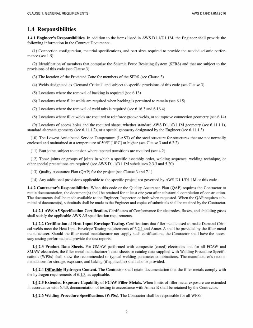
1.4 Responsibilities1.4.1 Engineer’s Responsibilities. In addition to the items listed in AWS D1.1/D1.1M, the Engineer shall provide thefollowing information in the Contract Documents:
(1) Connection configuration, material specifications, and part sizes required to provide the needed seismic perfor-mance (see 1.5)
(2) Identification of members that comprise the Seismic Force Resisting System (SFRS) and that are subject to theprovisions of this code (see Clause 3)
(3) The location of the Protected Zone for members of the SFRS (see Clause 3)
(4) Welds designated as “Demand Critical” and subject to specific provisions of this code (see Clause 3)
(5) Locations where the removal of backing is required (see 6.13)
(6) Locations where fillet welds are required when backing is permitted to remain (see 6.15)
(7) Locations where the removal of weld tabs is required (see 6.16.3 and 6.16.4)
(8) Locations where fillet welds are required to reinforce groove welds, or to improve connection geometry (see 6.14)
(9) Locations of access holes and the required shape, whether standard AWS D1.1/D1.1M geometry (see 6.11.1.1),standard alternate geometry (see 6.11.1.2), or a special geometry designated by the Engineer (see 6.11.1.3)
(10) The Lowest Anticipated Service Temperature (LAST) of the steel structure for structures that are not normallyenclosed and maintained at a temperature of 50°F [10°C] or higher (see Clause 3 and 6.2.2)
(11) Butt joints subject to tension where tapered transitions are required (see 4.2)
(12) Those joints or groups of joints in which a specific assembly order, welding sequence, welding technique, orother special precautions are required (see AWS D1.1/D1.1M subclauses 2.3.3 and 5.20)
(13) Quality Assurance Plan (QAP) for the project (see Clause 3 and 7.1)
(14) Any additional provisions applicable to the specific project not governed by AWS D1.1/D1.1M or this code.
1.4.2 Contractor’s Responsibilities. When this code or the Quality Assurance Plan (QAP) requires the Contractor toretain documentation, the document(s) shall be retained for at least one year after substantial completion of construction.The documents shall be made available to the Engineer, Inspector, or both when requested. When the QAP requires sub-mittal of document(s), submittals shall be made to the Engineer and copies of submittals shall be retained by the Contractor.
1.4.2.1 AWS A5 Specification Certification. Certificates of Conformance for electrodes, fluxes, and shielding gasesshall satisfy the applicable AWS A5 specification requirements.
1.4.2.2 Certification of Heat Input Envelope Testing. Certifications that filler metals used to make Demand Criti-cal welds meet the Heat Input Envelope Testing requirements of 6.2.1 and Annex A shall be provided by the filler metalmanufacturer. Should the filler metal manufacturer not supply such certifications, the Contractor shall have the neces-sary testing performed and provide the test reports.
1.4.2.3 Product Data Sheets. For GMAW performed with composite (cored) electrodes and for all FCAW andSMAW electrodes, the filler metal manufacturer’s data sheets or catalog data supplied with Welding Procedure Specifi-cations (WPSs) shall show the recommended or typical welding parameter combinations. The manufacturer’s recom-mendations for storage, exposure, and baking (if applicable) shall also be provided.
1.4.2.4 Diffusible Hydrogen Content. The Contractor shall retain documentation that the filler metals comply withthe hydrogen requirements of 6.1.3, as applicable.
1.4.2.5 Extended Exposure Capability of FCAW Filler Metals. When limits of filler metal exposure are extendedin accordance with 6.4.3, documentation of testing in accordance with Annex E shall be retained by the Contractor.
1.4.2.6 Welding Procedure Specifications (WPSs). The Contractor shall be responsible for all WPSs.
AWS D1.8/D1.8M:2016 CLAUSE 1. GENERAL REQUIREMENTS
3
1.4.2.7 Supplemental Welder Qualification Testing Documentation. The Contractor shall retain documentationthat welders performing Demand Critical complete joint penetration groove welding of beam bottom flange to columnT-joints have passed the Supplemental Welder Qualification for Restricted Access Welding test described in Annex D.
1.5 LimitationsThis code is intended to apply to the following:
(1) Structures made of steels with minimum specified yield strengths of 70 ksi [490 MPa] or less
(2) Structures that utilize steel with a minimum specified yield strength of 55 ksi [380 MPa] or less for the beams orbraces in which inelastic behavior is expected
1.6 Welding SymbolsWelding symbols shall be those shown in AWS A2.4:2007, Standard Symbols for Welding, Brazing, and NondestructiveExamination. Special conditions shall be fully explained by added notes or details.

This page is intentionally blank.
AWS D1.8/D1.8M:2016
4
AWS D1.8/D1.8M:2016
5
2. Normative References
The documents listed below are referenced within this publication and are mandatory to the extent specified herein. Forundated references, the latest edition of the referenced standard shall apply except where a specific edition is included inthe citation. For dated references, subsequent amendments to, or revisions of, any of these publications do not apply.
American Welding Society (AWS) Standards:
(1) AWS A2.4:2007, Standard Symbols for Welding, Brazing, and Nondestructive Examination
(2) AWS A3.0, Standard Welding Terms and Definitions, Including Terms for Adhesive Bonding, Brazing, Solder-ing, Thermal Cutting, and Thermal Spraying
(3) AWS A4.3, Standard Methods for Determination of the Diffusible Hydrogen Content of Martensitic, Bainitic,and Ferritic Steel Weld Metal Produced by Arc Welding
(4) AWS A5.01M/A5.01, Welding Consumables—Procurement of Filler Metals and Fluxes
(5) AWS A5.1/A5.1M, Specification for Carbon Steel Electrodes for Shielded Metal Arc Welding
(6) AWS A5.5/A5.5M, Specification for Low-Alloy Steel Electrodes for Shielded Metal Arc Welding
(7) AWS A5.17/A5.17M, Specification for Carbon Steel Electrodes and Fluxes for Submerged Arc Welding
(8) AWS A5.18/A5.18M, Specification for Carbon Steel Electrodes and Rods for Gas Shielded Arc Welding
(9) AWS A5.20/A5.20M, Specification for Carbon Steel Electrodes for Flux Cored Arc Welding
(10) AWS A5.23/A5.23M, Specification for Low-Alloy Steel Electrodes and Fluxes for Submerged Arc Welding
(11) AWS A5.25/A5.25M, Specification for Carbon and Low-Alloy Steel Electrodes and Fluxes for Electroslag Welding
(12) AWS A5.26/A5.26M, Specification for Carbon and Low-Alloy Steel Electrodes for Electrogas Welding
(13) AWS A5.28/A5.28M, Specification for Low-Alloy Steel Electrodes and Rods for Gas Shielded Arc Welding
(14) AWS A5.29/A5.29M, Specification for Low-Alloy Steel Electrodes for Flux Cored Arc Welding
(15) AWS A5.36/A5/36M:2012, Specification for Carbon and Low-Alloy Steel Flux Cored Electrodes for Flux CoredArc Welding and Metal Cored Electrodes for Gas Metal Arc Welding
(16) AWS B4.0, Standard Methods for Mechanical Testing of Welds
(17) AWS B5.1:2003, Specification for the Qualification of Welding Inspectors
(18) AWS C4.1, Criteria for Describing Oxygen-Cut Surfaces, and Oxygen Cutting Surface Roughness Gauge
(19) AWS D1.1/D1.1M, Structural Welding Code—Steel
(20) AWS QC1, Standard for AWS Certification of Welding Inspectors
American Institute of Steel Construction (AISC) Standards:
(1) AISC 341, Seismic Provisions for Structural Steel Buildings
6
CLAUSE 2. NORMATIVE REFERENCES AWS D1.8/D1.8M:2016
(2) AISC 358, Prequalified Connections for Special and Intermediate Moment Frames for Seismic Applications
(3) AISC 360, Specification for Structural Steel Buildings
(4) AISC Steel Construction Manual
American Society for Nondestructive Testing (ASNT) Standards:
(1) ASNT SNT-TC-1A, Recommended Practice for the Qualification and Certification of Nondestructive TestingPersonnel
(2) ASNT CP-189, Standard for the Qualification and Certification of Nondestructive Testing Personnel
Canadian Standards Association (CSA):
(1) CSA W178.2, Certification of Welding Inspectors
AWS D1.8/D1.8M:2016 CLAUSE 3. TERMS AND DEFINITIONS
7
3. Terms and Definitions
AWS A3.0, Standard Welding Terms and Definitions, Including Terms for Adhesive Bonding, Brazing, Soldering, Ther-mal Cutting, and Thermal Spraying, provides the basis for terms and definitions used herein. However, for the purposesof this document, the following terms and definitions apply:
demand critical welds. Welds designated by the Engineer in the contract documents, and required to meet specificrequirements of this code.
doubler. Plate added to, and parallel with, a beam or column web to increase the strength at locations of concentratedforces.
k-Area. The region of the web that extends from the tangent point of the web and the flange-web fillet (AISC k dimen-sion) a distance 1-1/2 in [40 mm] into the web beyond the k detail dimension.1
lowest anticipated service temperature (LAST). The lowest one (1) hour average temperature with a 100-year meanrecurrence interval.
protected zone. That portion of a member of the SFRS, designated by the Engineer in Contract Documents in whichinelastic straining is anticipated to occur and to which special limitations in these provisions apply with regard toattachments and fabrication.
quality assurance plan (QAP). The written description of qualifications, procedures, quality inspections, resources,and records to be used to provide assurance that the structure complies with the Engineer’s quality requirements,specifications, jurisdictional requirements, and Contract Documents.
seismic force resisting system (SFRS). The assembly of structural elements in the building that resists seismic loads, asindicated by the Engineer in the Contract Documents. Included in the SFRS are the columns, beams, girders andbraces, and the connections between these elements, specifically designed to resist seismic loads, either alone or incombination with other loads. The SFRS does not include other structural members not designed to resist seismicloads.
1 See AISC Specification for Structural Steel Buildings for formal definition of k detail dimension.

This page is intentionally blank.
AWS D1.8/D1.8M:2016
8
AWS D1.8/D1.8M:2016
9
4. Welded Connection Details
4.1 Corner Clips of Continuity Plates and Stiffeners
Corners of continuity plates and stiffeners shall be clipped as follows (see Figures C-4.1 and C-4.2):
4.1.1 Along the Web. The corner clip along the web shall be detailed so that the clip extends a distance of at least 1-1/2in [40 mm] beyond the published k detail dimension for the rolled shape.2
4.1.2 Along the Flange. The corner clip along the flange shall be detailed so that the clip does not exceed a distance of1/2 in [12 mm] beyond the published k1 dimension.3
4.1.3 Facilitating Suitable Weld Terminations. The corner clip shall be detailed to facilitate suitable weld terminationsof both the flange weld and the web weld.
4.1.4 Curved Corner Clips. Curved corner clips, if used, shall have a minimum radius of 1/2 in [12 mm].
4.2 Transitions in Thicknesses and Widths
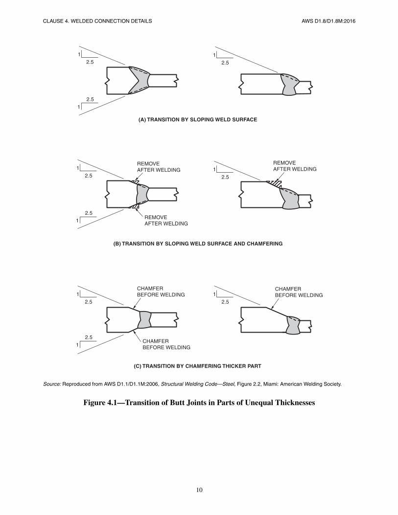
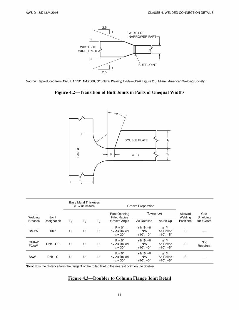
When butt joints subject to tension are required to be tapered, transitions shall be made in such manner that the slope inthe transition does not exceed 1 in 2-1/2 (see Figure 4.1 for thickness transitions and Figure 4.2 for width transitions).The transition shall be accomplished by chamfering the thicker part, tapering the wider part, sloping the weld metal orby a combination of these.
4.3 Joint Details for Doublers
Details of joints comprised of a web doubler and a hot rolled section fillet and flange that conform to Figure 4.3 shall beconsidered suitable for use in a prequalified WPS. Changes in the following joint variables in a joint which otherwise con-forms to Figure 4.3, shall require 3 macroetch tests cut at least 6 in [150 mm] from each other from a mockup assembly:
(1) a decrease in the groove angle, α
(2) a decrease in the root opening, R
4.3.1 Macroetch Specimen Acceptance Criteria.The macroetch specimens, when inspected visually, shall conform tothe following requirements:
(1) no cracks
(2) thorough fusion between adjacent layers of weld metal and between weld metal and base metal
2 See AISC 360 Specification for Structural Steel Buildings for formal definition of k detail dimension.3 See the AISC Steel Construction Manual Part 1 for k1 dimensions.
10
CLAUSE 4. WELDED CONNECTION DETAILS AWS D1.8/D1.8M:2016
Source: Reproduced from AWS D1.1/D1.1M:2006, Structural Welding Code—Steel, Figure 2.2, Miami: American Welding Society.
Figure 4.1—Transition of Butt Joints in Parts of Unequal Thicknesses
11
AWS D1.8/D1.8M:2016 CLAUSE 4. WELDED CONNECTION DETAILS
Source: Reproduced from AWS D1.1/D1.1M:2006, Structural Welding Code—Steel, Figure 2.3, Miami: American Welding Society.
Figure 4.2—Transition of Butt Joints in Parts of Unequal Widths
Figure 4.3—Doubler to Column Flange Joint Detail
Welding Process
Joint Designation
Base Metal Thickness(U = unlimited) Groove Preparation
Allowed Welding Positions
Gas Shieldingfor FCAWT1 T2 T3
Root OpeningFillet Radius
Groove Angle
Tolerances
As Detailed As Fit-Up
SMAW Dblr U U UR = 0*
r = As Rolledα = 20°
+1/16, –0N/A
+10°, –0°
±1/4As-Rolled+10°, –5°
F —
GMAWFCAW Dblr—GF U U U
R = 0*r = As Rolled
α = 30°
+1/16, –0N/A
+10°, –0°
±1/4As-Rolled+10°, –5°
F NotRequired
SAW Dblr—S U U UR = 0*
r = As Rolledα = 30°
+1/16, –0N/A
+10°, –0°
±1/4As-Rolled+10°, –5°
F —
*Root, R is the distance from the tangent of the rolled fillet to the nearest point on the doubler.
T1
T3WEB
DOUBLE PLATE
R
r
T2
FLA
NG
E
α

This page is intentionally blank.
AWS D1.8/D1.8M:2016
12
AWS D1.8/D1.8M:2016
13
5. Welder Qualification
5.1 Supplemental Welder Qualification Testing5.1.1 Required Tests. In addition to the requirements of AWS D1.1/D1.1M Clause 4, welders shall pass the Supple-mental Welder Qualification for Restricted Access Welding test as prescribed in Annex D, when the welder is requiredto make welds subject to all of the following requirements:
(1) The weld is a Demand Critical complete joint penetration groove weld.
(2) The weld joins the bottom beam flange to the column flange.
(3) The weld in the groove must be made by welding through a beam web weld access hole.
5.1.2 Testing Parameters. The Supplemental Welder Qualification for Restricted Access Welding test shall be per-formed in the flat position using the welding process that will be used in the work. The test shall be performed using adeposition rate equal to or greater than that to be used in production.
5.1.3 Backing. The Supplemental Welder Qualification for Restricted Access Welding test shall use the type of backingto be used on the project, except that, tests performed with no backing shall qualify the welder to use steel backing inproduction, but the reverse shall not be permitted.
If backing other than steel is used, or if no backing is used, the welder shall be qualified using the maximum root open-ing that will be permitted in production. If the project will use no backing, no backing shall be permitted on the qualifi-cation test.
5.1.4 Tack Welders. Tack welders are not required to perform the Supplemental Welder Qualification for RestrictedAccess Welding test described in Annex D.
5.2 Welder Qualification PeriodThe qualification for welding personnel using the Supplemental Welder Qualification for Restricted Access Weldingtest prescribed in Annex D shall remain valid for 36 months, providing the continuity requirements for process use ofAWS D1.1/D1.1M are met. Should the 36-month period elapse while welding on the project, the Supplemental WelderQualification for Restricted Access Welding qualification shall remain valid unless there is a specific reason to questionthe welder’s ability.
5.3 Welder Performance Qualification Record InformationWelder Performance Qualification Records for the Supplemental Welder Qualification for Restricted Access Weldingtest described in Annex D shall, as a minimum, provide all applicable essential variables contained in Table 4.11 ofAWS D1.1/D1.1M, and the following:
(1) Type of backing, if used
14
CLAUSE 5. WELDER QUALIFICATION AWS D1.8/D1.8M:2016
(2) Maximum root opening (if steel backing is not used)
(3) Minimum groove angle (if steel backing is not used)
(4) Maximum deposition rate
AWS D1.8/D1.8M:2016
15
6. Fabrication
Part AFiller Metal and Weld Metal
6.1 Filler Metal and Weld MetalAll welds governed by this code shall comply with all the requirements of 6.1. The requirements of 6.2.1, 6.2.2, 6.2.3,and 6.3.1 shall apply only to Demand Critical welds.
6.1.1 AWS A5 Specification Properties. Filler metals shall meet the requirements of Table 6.1 as determined from test-ing in accordance with the applicable AWS A5 specification.
6.1.2 Certification of AWS A5 Specification Properties and Diffusible Hydrogen. The manufacturer’s typical Certif-icate of Conformance shall be considered adequate proof that the supplied electrode or electrode-flux combination meetsthe requirements of 6.1.1 and 6.1.3. Testing of filler metal samples or of production welds shall not be required.
6.1.3 Diffusible Hydrogen Level. All welding electrodes and electrode-flux combinations shall meet the requirementsof Table 6.3.
6.1.4 Intermix of FCAW-S Filler Metal. When FCAW-S filler metals are used in combination with filler metals forother processes, including FCAW-G, supplemental notch toughness testing shall be conducted in accordance with one ormore of the following:
(1) Tests as described in Annex B;
(2) PQR tests that contain intermixed weld metal, wherein CVN test specimens have been taken from the intermixedzone;
(3) Alternative tests, as approved by the Engineer.
Regardless of the testing method used, the testing shall demonstrate that the acceptance criteria of Annex B are met.
Part BAdditional Requirements for Demand Critical Filler Metal and Weld Metal
6.2 Heat Input Envelope6.2.1 WPS Heat Input Envelope Testing Properties. Filler metals for Demand Critical welds shall provide themechanical properties in Table 6.2, based upon the WPS Heat Input Envelope Testing prescribed in Annex A, except thefollowing filler metals shall be exempted from the testing prescribed in Annex A when LAST is equal to or greater than+50°F [+10°C]:
16
CLAUSE 6. FABRICATION AWS D1.8/D1.8M:2016
(1) SMAW electrodes classified as E7018 [E4918], E7018-X [E4918-X], in AWS A5.1/A5.1M, and E7018-C3L[E4918-C3L], E8018-C3 [E5518-C3] in AWS A5.5/A5.5M (see 6.3.1.3);
(2) Solid GMAW electrodes classified in AWS A5.18/5.18M or AWS A5.28/A5.28M as ER70 or ER80 [ER49 orER55] tensile strength, as applicable (see 6.3.1.3);
(3) Carbon steel FCAW electrodes classified as E7X [E49X] with the “-D” designator as described in AWS A5.20/5.20M;
(4) AWS A5.29/5.29M E7X or E8X [E49X or E55X] low alloy FCAW electrodes, AWS A5.18/5.18M carbon steeland AWS A5.28/5.28M low alloy composite (metal cored) GMAW electrodes, and AWS A5.17/A5.17M carbon steel andAWS A5.23/5.23M low alloy electrode/flux SAW combinations that have been optionally tested by the filler metal man-ufacturer in accordance with AWS A5.20/A5.20M:2005 Clause 17 for the “-D” designator. The test plate for the “-D”testing of SAW filler metals may be performed on a 1 in [25 mm] test plate instead of the 3/4 in [18 mm] test plate man-dated by AWS A5.20/A5.20M.
(5) AWS A5.36/A5.36M:2012, electrodes classified to 80 ksi [550 MPa] tensile strength with the “-D” designator asdescribed in Clause 16 of AWS A5.36/A5.36M.
(6) E90 [E62] Low Alloy SMAW, FCAW, GMAW composite (metal cored) and solid electrodes, and low alloy elec-trode/flux SAW combinations that have been optionally tested by the filler metal manufacturer in accordance with AWSA5.20/A5.20M:2005 Clause 17 for the “-D” designator and meet 40 ft·lbs [54 J] at +50°F [+10°C]. The test plate for the“-D” testing of SAW filler metals may be performed on a 1 in [25 mm] test plate instead of the 3/4 in [18 mm] test platemandated by AWS A5.20/A5.20M.
6.2.2 Lowest Anticipated Service Temperature Applications. For Demand Critical welds in applications where theSeismic Force Resisting System is subjected to service temperatures below +50°F [+10°C] following completion of thestructure, the minimum CVN of 40 ft·lbf [54 J] as prescribed by 6.2.1 shall be provided at a test temperature not morethan 20°F [10°C] above the Lowest Anticipated Service Temperature for 70 ksi [490 MPa] and 80 ksi [550 MPa] fillermetals and at LAST for 90 ksi [620 MPa] filler metals. The exemptions in 6.2.1 and 6.3.1.3 shall not apply when LASTis less than +50°F [+10°C].
6.2.3 Testing Source. The WPS Heat Input Envelope Testing of Filler Metals, required for Demand Critical welds anddescribed in Annex A, shall be performed by the filler metal manufacturer, by the Contractor, or by a third party accept-able to the Engineer. The Contractor shall be responsible to ensure that this testing has been performed for the filler met-als to be used, regardless of the testing source.
6.3 Production Lot Control6.3.1 Filler Metal Production Lot Control. Each production lot of filler metal used to make Demand Critical weldsshall be tested in conformance with the applicable AWS A5 specification filler metal classification tests. In addition tothe standard AWS A5 specification testing, high and low heat input testing shall be performed in accordance with one ofthe requirements below at the Contractor’s option.
(1) Annex A;
(2) A5.20/A5.20M:2005 Clause 17 for the “-D” designator;
(3) A5.36/A5.36M:2012 Clause 16 for the “-D” designator.
6.3.1.1 Production Lots. Production lots shall be as defined in AWS A5.01M/A5.01. Production lots shall meet thefollowing requirements:
(1) Class C3 or C4 for SMAW electrodes
(2) Class S3 or S4 for solid electrodes for GMAW and SAW
(3) Class T3 or T4 for FCAW and composite electrodes for GMAW and SAW
(4) Class F2 for SAW fluxes
PART B
AWS D1.8/D1.8M:2016 CLAUSE 6. FABRICATION
17
6.3.1.2 Alternative to Production Lot Testing. Filler metals shall be exempt from production lot testing, provided aminimum of 3 different lots of material, as defined in 6.3.1.1, for each trade name and diameter to be used in production,are first tested in accordance with Annex A when produced by manufacturers audited and approved by one or more ofthe following agencies:
(1) American Bureau of Shipping (ABS)
(2) Lloyd’s Register of Shipping
(3) American Society of Mechanical Engineers (ASME)
(4) U.S. Department of Defense
(5) A quality assurance program acceptable to the Engineer
To remain exempt from production lot testing, the manufacturer shall perform the test as described in Annex A, on atleast one lot of material, at a frequency not to exceed three years, for each trade name and diameter of electrode to beused in production.
6.3.1.3 Exemptions. For LAST greater than or equal to +50°F [+10°C], SMAW with AWS A5.1/A5.1M E7018[E4918], AWS A5.1/A5.1M E7018-X [E4918-X], AWS A5.5/A5.5M E7018-C3L [E4918-C3L], and AWSA5.5/A5.5M E8018-C3 [E5518-C3] electrodes, and ER70 and ER80 [ER49 and ER55] GMAW solid electrodes shall beexempted from lot testing when the CVN toughness of the weld metal deposited with the electrode equals or exceeds 20ft·lbf [27 J] at a temperature not exceeding 0°F [–18°C], when tested in accordance with the applicable AWS A5 fillermetal specification. The manufacturer’s Certificate of Conformance shall be considered sufficient evidence of meetingthis requirement.
6.4 FCAW Electrode Packaging, Storage, and Exposure
The following provisions shall be applicable for Demand Critical welds:
6.4.1 Packaging Condition. Electrodes shall be provided in protective packaging that limits the ability of the electrodeto absorb moisture. When removed from the packaging, the electrode shall be capable of depositing weld metal with amaximum diffusible hydrogen content not to exceed the limits of 6.1.3. Electrode from packaging that has been punc-tured or torn shall be dried in accordance with the electrode manufacturer’s recommendations, or shall not be used forDemand Critical welds.
6.4.2 Modification of Electrodes. Modification or lubrication of the electrode after manufacture is prohibited, exceptthat drying as recommended by the manufacturer is permitted.
6.4.3 Exposure Time Limits for FCAW Electrodes. After removal from protective packaging, the permissible atmo-spheric exposure time of FCAW electrodes shall be limited as follows:
(1) Exposure shall not exceed the electrode manufacturer’s guidelines, when the guidelines are based upon electrodeexposure tests conducted in accordance with Annex E.
(2) In the absence of test data required in (1), the electrode may be tested in accordance with Annex E, and the resultsof such tests used as the basis for the exposure limits.
(3) In the absence of test data prescribed by (1) or (2), the total accumulated exposure time for FCAW electrodesshall not exceed 72 hours. Storage time in a protective package or cabinet shall not be included in the accumulated expo-sure time.
6.4.4 Overexposed FCAW Electrode. Electrodes that have been exposed to the atmosphere for periods that exceed thelimits of 6.4.3 shall be dried in accordance with the electrode manufacturer’s recommendations, or shall not be used forDemand Critical welds. The electrode manufacturer’s recommendations shall include time, temperature, and number ofdrying cycles permitted.
PART B
18
CLAUSE 6. FABRICATION AWS D1.8/D1.8M:2016
Part CWelding Procedure Specifications
6.5 Welding Processes
6.5.1 Approved Processes for Demand Critical Welds. SMAW, GMAW (except short circuit transfer), FCAW, andSAW may be used to make Demand Critical welds governed by this code. Other processes may be used, provided thatone or more of the following criteria is met:
(1) The process is part of the prequalified connection details, as described in AISC 341;
(2) The process is permitted for the connection in AISC 358;
(3) The process was used to perform a satisfactory connection qualification test in accordance with AISC 341;
(4) The process is approved by the Engineer.
6.6 Welding Procedure Specifications (WPSs)
6.6.1 General. WPSs shall be prequalified, or shall be qualified by test, in accordance with applicable AWSD1.1/D1.1M requirements.
6.6.2 WPS Content. The WPS shall specify all applicable essential variables of AWS D1.1/D1.1M. For Demand Criti-cal welds, the WPS shall additionally list the following essential variables:
(1) Electrode manufacturer and trade name;
(2) For filler metal types, welding processes and filler metal strength levels listed in 6.8, WPSs shall list one or morecombinations of variables that produce heat input limits listed in 6.8.1.
6.6.3 Air Velocity Limits
6.6.3.1 Gas-Shielded Processes. Welding with the GMAW and FCAW-G processes shall not be performed in windsexceeding 3 mph [5 kph]. Windscreens or shelters may be used to shield the welding operation from excessive wind.
6.6.3.2 Non Gas-Shielded Processes. SMAW, FCAW-S, and SAW may be performed without limitation to airvelocity, provided the welds meet the visual acceptance criteria.
6.7 Maximum Interpass Temperature
6.7.1 Standard Maximum Interpass Temperature. The maximum interpass temperature shall not exceed 550°F[300°C], unless an alternate value is qualified in accordance with 6.7.2. The maximum interpass temperature shall bemeasured at a distance of 1 in to 3 in [25 mm to 75 mm] from the joint.
6.7.2 Alternative Maximum Interpass Temperature. The temperature limit of 6.7.1 may be increased by qualificationtesting. The qualification testing shall be performed in accordance with AWS D1.1/D1.1M. The maximum heat input tobe used in production shall be used in the qualification testing. The qualified maximum interpass temperature shall bethe lowest interpass temperature used for any pass during qualification testing. The weld metal and HAZ shall be tested.The weld metal shall meet all the mechanical properties required by 6.1.1 and 6.2.1, as applicable. The HAZ CVNtoughness shall be tested in accordance with AWS D1.1/D1.1M Clause 4, Qualification, and shall meet the minimumrequirement shown in Table 6.1 with specimens taken at both 1 mm and 5 mm from the fusion line. The steel used forthe qualification testing shall be of the same type and grade as will be used in production.
PART C
AWS D1.8/D1.8M:2016 CLAUSE 6. FABRICATION
19
6.8 Heat Input
6.8.1 Heat Input Limits. Acceptable heat input limits on WPSs for Demand Critical welds shall include the following,at the Contractor’s option:
(1) The heat input range qualified by testing in accordance with Annex A
(2) For carbon steel FCAW electrodes classified with the supplemental designator “-D,” the heat input range pre-scribed in Clause 17 of AWS A5.20/A5.20M:2005
(3) The heat input range prescribed in AWS A5.20/A5.20M:2005 Clause 17 for the following 70 ksi or 80 ksi[490 MPa or 550 MPa] tensile strength filler metals when optionally tested to the requirements of the AWS A5.20/A5.20M “-D” supplemental designator:
(a) Low alloy FCAW electrodes, classified to AWS A5.29/A5.29M;
(b) Carbon steel GMAW composite (metal cored) electrodes, classified to AWS A5.18/A5.18M, and low alloyGMAW composite (metal cored) electrodes, classified to AWS A5.28/A5.28M;
(c) Carbon steel SAW electrode/flux combinations, classified to AWS A5.17/A5.17M, and low alloy SAW elec-trode/flux combinations, classified to AWS A5.23/A5.23M.
(4) Low alloy electrodes classified as 90 ksi [620 MPa] tensile strength, SMAW, GMAW metal core and solid elec-trodes, FCAW electrodes, and SAW electrode/flux combinations, the heat input range qualified by testing in accordancewith (1) or (3) and meet the requirements of the 90 ksi [620 MPa] classification with CVN requirement of 40 ft·lbf [54 J]@+50°F [+10°C].
(5) The heat input range prescribed in AWS A5.36/A5.36M:2012 Clause 16 for carbon and low alloy steel FCAWand GMAW-metal core electrodes classified with the supplemental designator “-D.”
NOTE: The “-D” designator of AWS A5.36/A5.36M does not have the same requirements for heat input as AWSA5.20/A5.20M “-D” designator, and therefore are not interchangeable in a WPS(s). Heat inputs of AWSA5.36/A5.36M “-D” designator requirements may overlap in some heat inputs of AWS A5.20/A5.20M “-D” desig-nator. The high heat input of AWS A5.36/A5.36M “-D” designator is a range, with the lower bounds having aminimum heat input of 65 kJ/in [2.6 kJ/mm] for both FCAW and GMAW-composite (metal core) electrodes. Thefabricator shall be limited to the low and high heat input operating range as established by the electrode manufac-turer under the AWS A5.36/A5.36M “-D” requirements.
6.9 Bottom Flange Welding Sequence
Complete joint penetration groove welds of beam bottom flanges to column flanges, or to continuity plates, using weldaccess holes shall be sequenced as follows:
(1) As far as is practicable, starts and stops shall not be directly under the beam web.
(2) Each layer shall be completed across the full width of the flange before beginning the next layer.
(3) For each layer, the weld starts and stops shall be on the opposite side of the beam web, as compared to the previ-ous layer.
6.10 Welder Identification
The Contractor shall establish and implement a means by which the welder(s) welding on each joint can be identifiedand associated with the specific joint. Stamps, if used, shall be the low-stress type.
PART C
20
CLAUSE 6. FABRICATION AWS D1.8/D1.8M:2016
Part DDetails
6.11 Weld Access Holes
Weld access holes for all Demand Critical welds shall conform to the following:
6.11.1 Shape
6.11.1.1 Standard AWS D1.1/D1.1M Geometry. Unless otherwise specified in Contract Documents, all weldaccess holes shall meet the dimensions and tolerances of AWS D1.1/D1.1M or AISC 360. At the option of the Contrac-tor, the geometry of 6.11.1.2 may be substituted for the 6.11.1.1 geometry.
6.11.1.2 Alternate Geometry. When required by Contract Documents, the weld access hole dimensions and toler-ances, and geometry shall comply with Figure 6.2.
6.11.1.3 Special Geometry. When a special geometry is required by Contract Documents, the weld access holegeometry shall comply with those dimensions and tolerances specified.
6.11.2 Quality Requirements for Weld Access Holes
6.11.2.1 Surface Roughness. Except for access holes using AWS D1.1/D1.1M standard geometry, or when other-wise specified by the Engineer, the weld access hole finish shall have a surface roughness of not more than 500 µin [13µm]. AWS C4.1, Criteria for Describing Oxygen-Cut Surfaces, and Oxygen Cutting Surface Roughness Gauge, Sample4, may be used as a guide for evaluating surface roughness of these surfaces.
6.11.2.2 Notches and Gouges. Notches or gouges in the weld access hole, including those from thermal cutting andmisaligned saw cuts, shall be removed by grinding, faired to a slope of not more than 1:5 against a straight cut surface, orto a radius of not less than 3/8 in [10 mm] if in the curved portion of the cut surface. The depth of notches and gougesthat may be repaired by grinding is not limited, provided the final shape of the weld access hole meets the requireddimensions, tolerances, and profiles.
6.11.2.3 Repair of Notches by Welding. Notches deeper than those that can be repaired by grinding (as defined in6.11.2.2) may be repaired by welding. Prior to welding, the notch or gouge shall be ground to provide a smooth contourwith a radius not less than 1/4 in [6 mm]. The repair area shall be preheated to a temperature of not less than 150°F[65°C]. A written repair WPS for this application shall be followed. Following completion of welding, the area shall beground, and the overall area made smooth and flush to meet the contour and finish requirements for the access hole, withfairing of the welded surface to adjoining surfaces.
6.12 Tack Welding Requirements
6.12.1 Preheat. Preheat for all tack welds shall be as required by the WPS.
6.12.2 Placement of Tack Welds. In the Protected Zone, unless specifically required or permitted by the Engineer andshown on detail drawings, tack welds shall be prohibited outside the weld joint.
6.12.3 Tack Welds to Steel Backing in the Protected Zone. Tack welds between backing and the beam flange outsidethe weld joint shall be prohibited. Tack welds that attach steel backing to groove welds in the Protected Zone shall beplaced within the weld joint, when practicable, with the following exception: steel backing may be tack welded to col-umns for beam flange to column flange welds.
6.12.4 Removal of Improperly Placed Tack Welds. Improperly placed tack welds shall be removed by grinding.Gouges or notches shall be repaired in accordance with 6.18.5.2.
PART D
AWS D1.8/D1.8M:2016 CLAUSE 6. FABRICATION
21
6.13 Removal of Backing and Weld Root TreatmentWhen fusible (steel) backing is required to be removed, removal shall be by air carbon arc gouging (CAG), plasma arcgouging (PAG), grinding, chipping, or other thermal cutting processes. The process shall be controlled to minimizeerrant gouging. After backing removal (both for steel and nonfusible backing), the weld root shall be backgouged tosound metal. Backgouged joints shall be filled with weld metal, as necessary, to achieve at least a flush condition. Theweld shall be deposited in accordance with an applicable WPS. Gouges that remain after any back welding or fillet weld-ing is performed shall be repaired. Notches and gouges not greater than 1/16 in [1.5 mm] deep shall be faired to a slopenot greater than 1:5. Deeper notches shall be repaired by welding in accordance with an applicable WPS.
6.14 Reinforcing Fillet Welds at Removed Weld Backing LocationsWhen reinforcing fillet welds are required at locations where steel backing has been removed, the minimum size shall be5/16 in [8 mm]. The leg of the fillet adjacent to the beam flange shall be such that the fillet toe is located on base metal,except that if the back weld and base metal is ground smooth after removal of backing, the fillet need not extend to thebase metal. See Figure 6.1.
6.15 Fillet Welds at Left-in-Place Steel Backing6.15.1 Minimum Fillet Weld Size. When a fillet weld is required between the left-in-place steel backing and the col-umn, the minimum size shall be 5/16 in [8 mm].
6.15.2 Prohibited Welds on Left-in-Place Steel Backing. Steel backing at beam flange to column flange joints shallnot be welded to the underside of the beam flange. Tack welds shall not be permitted in this area.
6.16 Weld Tabs6.16.1 Minimum Weld Tab Length. Where practicable, weld tabs shall extend a minimum of 1 in [25 mm] or thethickness of the part, whichever is greater, beyond the edge of the joint. Weld tab length need not exceed 2 in [50 mm].Where there is inadequate access for weld tabs, such as with closely spaced pieces or pieces intersecting at acute angles,weld ends may be cascaded for approximately one weld size.
6.16.2 Tack Welds Attaching Weld Tabs. Tack welds attaching weld tabs in the Protected Zone shall be made withinthe joint, and shall meet the requirements of 6.12.
6.16.3 Weld Tab Removal—General. When weld tabs are required by Contract Documents to be removed, weld tabsshall be removed and the end of the weld finished. Removal shall be by air carbon arc gouging (CAG), grinding, chip-ping, or thermal cutting. The process shall be controlled to minimize errant gouging. The edges where weld tabs havebeen removed shall have a surface roughness of not more than 500 µin [13 µm]. AWS C4.1, Criteria for DescribingOxygen-Cut Surfaces, and Oxygen Cutting Surface Roughness Gauge, Sample 4, may be used as a guide for evaluatingsurface roughness of these surfaces. Grinding to a flush condition is not required. The contour of the weld shall providea smooth transition, free of notches and sharp corners. At T-joints, a minimum radius in the corner need not be provided.The weld end shall be free of defects. Defects not greater than 1/16 in [1.5 mm] deep shall be removed by grinding andfaired to a slope not greater than 1:5. Other defects shall be excavated and repaired by welding in accordance with anapplicable WPS. See Figure 6.3.
6.16.4 Weld Tabs for Continuity Plates. Weld tabs for continuity plates shall not be used at the end of the weld adja-cent to the column web-to-flange juncture, except when permitted or required by the Engineer. Unless specified to beremoved by the Engineer, weld tabs shall not be removed when used in this location.
6.17 End Dams6.17.1 Material. End dams may be metallic or nonmetallic.
PART D
22
CLAUSE 6. FABRICATION AWS D1.8/D1.8M:2016
6.17.2 Placement. End dams shall not be placed at either end of the weld joint, except as follows: end dams may be placedat the outboard ends of the weld tabs, provided the weld tabs are removed upon completion of the weld (see Figure 6.4).
Part EProtected Zone
6.18 Protected Zone6.18.1 Attachments and Welds. Welded attachments, including stud welds and fasteners for the connection of othermaterials, shall be prohibited within the Protected Zone. Arc spot welds (puddle welds) for the attachment of metaldecking shall be permitted in the Protected Zone.
6.18.2 Erection Aids. If erection aids are required to be attached within the Protected Zone, the Contractor shall obtainthe Engineer’s approval for the use of such attachments.
6.18.3 Removal of Welds in Protected Zone. When welds in the Protected Zone are required to be removed, removalshall be by air carbon arc cutting (CAC-A), grinding, chipping, or other thermal cutting processes. The process shall becontrolled to minimize errant gouging. After removal, the area shall be ground smooth and shall be free of defects.
6.18.4 Correction of Errors. If fillet welds or tack welds are placed between the backing and the beam flange in error,they shall be repaired as follows:
(1) The weld shall be removed such that the fillet weld or tack weld no longer attaches the backing to the beam flange.
(2) The surface of the beam flange shall be ground flush and shall be free of defects.
(3) Any gouges or notches shall be repaired in accordance with 6.18.5.
6.18.5 Repair of Gouges and Notches. Gouges and notches in the Protected Zone shall be repaired as follows:
6.18.5.1 Grinding. When gouges and notches are repaired by grinding, the ground area shall provide a gradual taperto the surface of the base metal. In the direction parallel to the member axis, the taper shall not be greater than 1:5. In thedirection transverse to the member axis, the taper shall not be greater than 1:2.5.
6.18.5.2 Repair Welding of Gouges and Notches. When repairs require welding, the notch or gouge shall beremoved and ground to provide a smooth radius of not less than 1/4 in [6 mm] in preparation for welding. Welding shallbe done in accordance an applicable WPS. Preheat shall be in accordance with AWS D1.1/D1.1M, but shall not be lessthan 150°F [65°C]. Electrodes shall comply with 6.1. Following welding, the repair weld shall be ground to a smoothcontour with a surface roughness not to exceed 500 µin [13 µm]. AWS C4.1, Criteria for Describing Oxygen-Cut Sur-faces, and Oxygen Cutting Surface Roughness Gauge, Sample 4, may be used as a guide for evaluating surface rough-ness of these surfaces. After repair, the area shall be inspected using magnetic particle testing (MT). The resultantthickness of the repaired area shall be at least the base metal thickness less 1/16 in [1.5 mm].
6.18.6 Repair of Mislocated Holes. Where the Engineer requires welded restoration of holes in the Protected Zone, aprocedure shall be developed by the Contractor and approved by the Engineer. The procedure shall include an appropri-ate WPS with a minimum preheat of 150°F [65°C], a requirement to grind the weld reinforcement surface flush asdefined in AWS D1.1/D1.1M Clause 5 and verification of the soundness of the weld using both magnetic particle testingand ultrasonic testing.
6.18.7 Repair of Mislocated Stud Welds. Mislocated studs in the Protected Zone shall be cut off and ground flush.
6.18.8 Repair of Mislocated Screws and Shot Pins. Where mislocated pins or screws are required by the Engineer tobe repaired by welding, a procedure shall be developed by the Contractor and approved by the Engineer. The procedureshall include an appropriate WPS with a minimum preheat of 150°F [65°C], and shall include the shape of the excava-tion to be restored by welding. Grinding or gouging shall be performed to the depth of the pin or screw. The welded sur-face shall be ground flush. The weld soundness shall be verified by both magnetic particle testing and ultrasonic testing.
PARTS D & E
23
AWS D1.8/D1.8M:2016 CLAUSE 6. FABRICATION
Table 6.1Filler Metal Mechanical Property Requirements
Property
Classification Strength Levels
70 ksi [490 MPa] 80 ksi [550 MPa] 90 ksi [620 MPa]
Yield Strength, ksi [MPa] a 58 [400] min. 68 [470] min. 78 [540] min.
Tensile Strength, ksi [MPa] 70 [490] min. 80 [550] min. 90 [620] min.
Elongation (%) 22 min. 19 min. 17 min.
CVN Toughness, ft·lbf [J] b 20 [27] min. @ 0°F [–18°C] 20 [27] min. @ 0°F [–18°C] 25 [34] min. @ –20°F [–30°C]
a 0.2% offset method.b Filler metals classified as meeting the required absorbed energy at a temperature lower than the required test temperature also meet this requirement.
Table 6.2Mechanical Property Requirements for Demand Critical Welds
Property
Classification Strength Levels
70 ksi [490 MPa] 80 ksi [550 MPa] 90 ksi [620 MPa]
Yield Strength, ksi [MPa] a 58 [400] min. 68 [470] min. 78 [540] min.
Tensile Strength, ksi [MPa] 70 [490] min. 80 [550] min. 90 [620] min.
Elongation (%) 22 min. 19 min. 17 min.
CVN Toughness, ft·lbf [J] b, c 40 [54] min. @ +70°F [+20°C] 40 [54] min. @ +70°F [+20°C] 40 [54] min. @ +50°F [+10°C]
a 0.2% offset method.b For LAST of +50°F [+10°C]. For LAST less than + 50°F [+10°C], see 6.2.2.c Tests conducted in accordance with Annex A meeting 40 ft·lbf [54 J] min. at a temperature lower than the required test temperature also meet this
requirement.
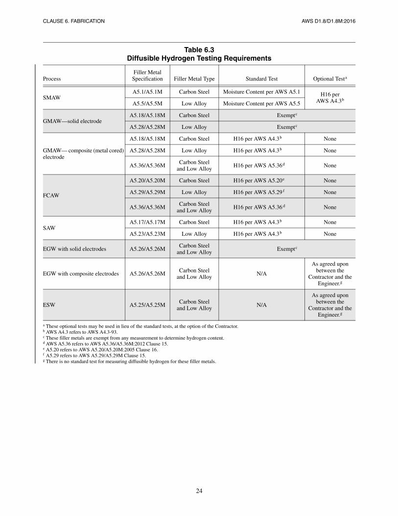
24
CLAUSE 6. FABRICATION AWS D1.8/D1.8M:2016
Table 6.3Diffusible Hydrogen Testing Requirements
ProcessFiller Metal
Specification Filler Metal Type Standard Test Optional Testa
SMAWA5.1/A5.1M Carbon Steel Moisture Content per AWS A5.1 H16 per
AWS A4.3bA5.5/A5.5M Low Alloy Moisture Content per AWS A5.5
GMAW—solid electrodeA5.18/A5.18M Carbon Steel Exemptc
A5.28/A5.28M Low Alloy Exemptc
GMAW— composite (metal cored) electrode
A5.18/A5.18M Carbon Steel H16 per AWS A4.3b None
A5.28/A5.28M Low Alloy H16 per AWS A4.3b None
A5.36/A5.36M Carbon Steeland Low Alloy
H16 per AWS A5.36d None
FCAW
A5.20/A5.20M Carbon Steel H16 per AWS A5.20e None
A5.29/A5.29M Low Alloy H16 per AWS A5.29 f None
A5.36/A5.36M Carbon Steeland Low Alloy H16 per AWS A5.36 d None
SAWA5.17/A5.17M Carbon Steel H16 per AWS A4.3b None
A5.23/A5.23M Low Alloy H16 per AWS A4.3b None
EGW with solid electrodes A5.26/A5.26MCarbon Steel
and Low Alloy Exemptc
EGW with composite electrodes A5.26/A5.26M Carbon Steeland Low Alloy N/A
As agreed upon between the
Contractor and the Engineer.g
ESW A5.25/A5.25M Carbon Steeland Low Alloy N/A
As agreed upon between the
Contractor and the Engineer.g
a These optional tests may be used in lieu of the standard tests, at the option of the Contractor.b AWS A4.3 refers to AWS A4.3-93.c These filler metals are exempt from any measurement to determine hydrogen content.d AWS A5.36 refers to AWS A5.36/A5.36M:2012 Clause 15.e A5.20 refers to AWS A5.20/A5.20M:2005 Clause 16.f A5.29 refers to AWS A5.29/A5.29M Clause 15.g There is no standard test for measuring diffusible hydrogen for these filler metals.
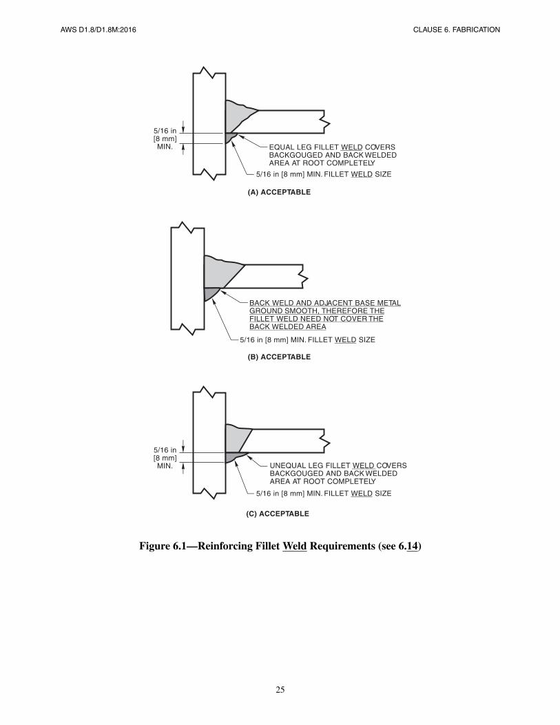
25
AWS D1.8/D1.8M:2016 CLAUSE 6. FABRICATION
Figure 6.1—Reinforcing Fillet Weld Requirements (see 6.14)
(C) ACCEPTABLE
5/16 in[8 mm]MIN. UNEQUAL LEG FILLET WELD COVERS
BACKGOUGED AND BACK WELDEDAREA AT ROOT COMPLETELY
5/16 in [8 mm] MIN. FILLET WELD SIZE
(B) ACCEPTABLE
BACK WELD AND ADJACENT BASE METALGROUND SMOOTH, THEREFORE THEFILLET WELD NEED NOT COVER THEBACK WELDED AREA
(A) ACCEPTABLE
5/16 in[8 mm]MIN. EQUAL LEG FILLET WELD COVERS
BACKGOUGED AND BACK WELDEDAREA AT ROOT COMPLETELY
5/16 in [8 mm] MIN. FILLET WELD SIZE
5/16 in [8 mm] MIN. FILLET WELD SIZE
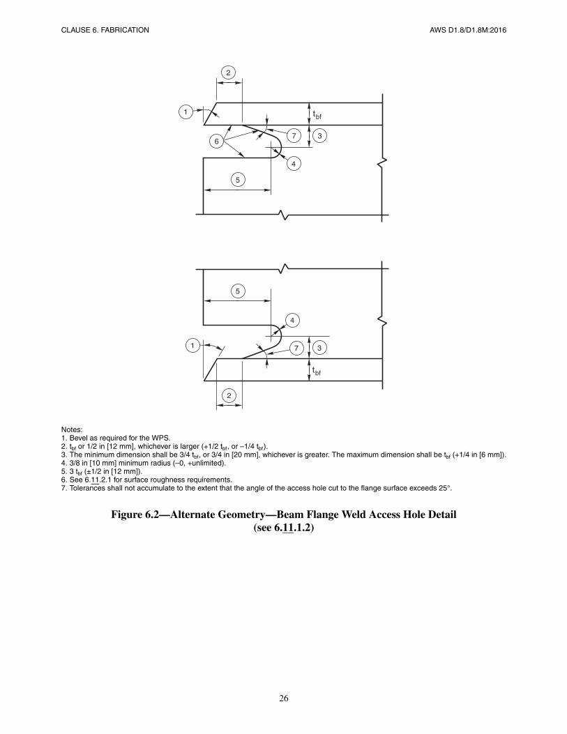
26
CLAUSE 6. FABRICATION AWS D1.8/D1.8M:2016
Notes:1. Bevel as required for the WPS.2. tbf or 1/2 in [12 mm], whichever is larger (+1/2 tbf, or –1/4 tbf).3. The minimum dimension shall be 3/4 tbf, or 3/4 in [20 mm], whichever is greater. The maximum dimension shall be tbf (+1/4 in [6 mm]).4. 3/8 in [10 mm] minimum radius (–0, +unlimited).5. 3 tbf (±1/2 in [12 mm]).6. See 6.11.2.1 for surface roughness requirements.7. Tolerances shall not accumulate to the extent that the angle of the access hole cut to the flange surface exceeds 25°.
Figure 6.2—Alternate Geometry—Beam Flange Weld Access Hole Detail(see 6.11.1.2)
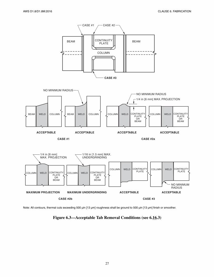
27
AWS D1.8/D1.8M:2016 CLAUSE 6. FABRICATION
Note: All contours, thermal cuts exceeding 500 µin [13 µm] roughness shall be ground to 500 µin [13 µm] finish or smoother.
Figure 6.3—Acceptable Tab Removal Conditions (see 6.16.3)
BEAM
CASE #1
COLUMN
BEAM CONTINUITYPLATE
CASE #3
NO MINIMUM RADIUS
ACCEPTABLE
BEAM WELD COLUMN
ACCEPTABLE
BEAM WELD COLUMN
ACCEPTABLE
WELD CONTINUITYPLATE
ORBEAM
1/4 in [6 mm] MAX. PROJECTION
ACCEPTABLE
WELD CONTINUITYPLATE
ORBEAM
CASE #2a
CASE #2b
MAXIMUM PROJECTION MAXIMUM UNDERGRINDING ACCEPTABLE
WELD CONTINUITYPLATE
ACCEPTABLE
CASE #3
NO MINIMUMRADIUS
WELD CONTINUITYPLATE
ORBEAM
1/4 in [6 mm]MAX. PROJECTION
1/16 in [1.5 mm] MAX.UNDERGRINDING
WELD CONTINUITYPLATE
ORBEAM
WELD CONTINUITYPLATE
COLUMN COLUMN
COLUMN COLUMN
COLUMN COLUMN
CASE #2CASE #1
NO MINIMUM RADIUS
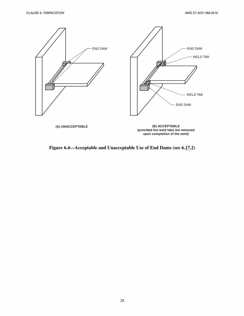
28
CLAUSE 6. FABRICATION AWS D1.8/D1.8M:2016
Figure 6.4—Acceptable and Unacceptable Use of End Dams (see 6.17.2)
(A) UNACCEPTABLE
END DAM END DAM
END DAM
WELD TAB
WELD TAB
(B) ACCEPTABLE(provided the weld tabs are removed
upon completion of the weld)
AWS D1.8/D1.8M:2016
29
7. Inspection
7.1 Inspection Task Assignment
When required by the Applicable Building Code or Contract Documents, the Engineer shall prepare a Quality AssurancePlan (QAP). The Quality Assurance Plan shall identify the specific Quality Control and Quality Assurance tasks to beperformed on the project respectively by the Contractor and the Quality Assurance (QA) Agency. The Contractor andQuality Assurance Agency shall perform those tasks as identified in the Quality Assurance Plan.
7.2 Inspector Qualifications
7.2.1 QA Welding Inspector Qualifications. QA Welding Inspectors shall be qualified in accordance with one or moreof the following:
(1) Welding Inspectors (WIs), or Senior Welding Inspectors (SWIs), as defined in AWS B5.1:2003, Standard for theQualification of Welding Inspectors, except Associate Welding Inspectors (AWIs) may be used under the direct supervi-sion of WIs, who are on site and available when weld inspection is being conducted, or
(2) Certified Welding Inspectors (CWIs), or Senior Certified Welding Inspectors (SCWIs) in accordance with therequirements of AWS QC1, Standard for AWS Certification of Welding Inspector, except Certified Associate WeldingInspectors (CAWIs) may be used under the direct supervision of CWIs, who are on site and available when weld inspec-tion is being conducted.
(3) Level 2 Welding Inspectors or Level 3 Welding Inspectors, certified in accordance with the requirements of theCanadian Welding Bureau (CWB) in conformance with the Canadian Standard Association (CSA) Standard W178.2,Certification of Welding Inspectors, except Level 1 Welding Inspectors may be used under the direct supervision ofLevel 2 Welding Inspectors, who are on site and available when weld inspection is being conducted.
7.2.2 QA NDT Personnel Qualifications. Nondestructive testing personnel shall be qualified in accordance with theiremployer’s written practice which shall meet or exceed the criteria of the American Society for Nondestructive Testing(ASNT) Recommended Practice SNT-TC-1A, Recommended Practice for the Qualification and Certification of Non-destructive Testing Personnel, or CP-189, Standard for the Qualification and Certification of Nondestructive TestingPersonnel.
7.2.3 Quality Control (QC) Welding Inspector Qualifications. QC welding inspection personnel shall be AssociateWelding Inspectors (AWI) or higher as defined in AWS B5.1:2003, or otherwise qualified under the provisions of AWSD1.1/D1.1M 6.1.4, and to the satisfaction of the Contractor’s QC program.
7.2.4 UT Technicians. Ultrasonic testing (UT) for QA shall be performed only by UT technicians:
(1) Certified as Level II or Level III by their employer, or
(2) Certified as ASNT Level III through examination by the ASNT.
Additionally, all UT technicians shall be certified by their employer as prescribed in Annex F for flaw detection.
30
CLAUSE 7. INSPECTION AWS D1.8/D1.8M:2016
7.3 Quality Assurance Agency Written PracticeThe QA Agency shall perform work in accordance with a Written Practice. The Written Practice shall contain descrip-tions of the following:
(1) The training, experience, and examination required for qualification and certification of inspection personnel;
(2) Procedures for the selection and administration of inspection personnel;
(3) The Agency’s inspection procedures, including general inspection, material controls, and visual welding inspection;
(4) The Agency’s procedures for determining the acceptability of the structure in accordance with the applicablecodes, standards, and specifications.
7.4 Wide-Flange k-Area InspectionWhen required by the QAP, MT of the member web shall be performed after welding of doubler plates, continuity plates orstiffeners in the k-area. The member web area to be tested for cracks using MT shall include the k-area base metal within3 in [75 mm] of the weld. The MT shall be performed no sooner than 48 hours following completion of the welding.
7.5 Lamellar TearingWhen required by the QAP, base metal shall be ultrasonically tested after welding for laminations and lamellar tearing.Any base metal discontinuities found within t/4 of the steel surface adjacent to the fusion line shall be accepted orrejected on the basis of criteria of AWS D1.1/D1.1M Table 6.2.
7.6 Beam Copes and Weld Access HolesWhen required by the QAP, beam copes and weld access holes shall be inspected for cracks on the cut surface prior towelding. Inspection shall be performed using MT or dye penetrant testing (PT).
7.7 Repaired Weld Access Holes in the Protected ZoneInspection of repairs to a weld access hole in the Protected Zone shall be by MT or PT.
7.8 NDT of Repaired Tab Removal SitesIf a repair to a weld tab removal site is made by additional welding, MT shall be performed in the repaired area and areaimmediately adjacent to the repair.
7.9 Magnetic Particle Testing RequirementsMagnetic particle testing (MT) shall be performed using the yoke method in accordance with written procedure that con-forms to Annex G.
7.10 Ultrasonic Testing7.10.1 Technique. Ultrasonic testing (UT) of welds required by the Quality Assurance Plan shall be performed accord-ing to the procedures prescribed in AWS D1.1/D1.1M Clause 6, Part F, following a written procedure containing the ele-ments prescribed in AWS D1.1/D1.1M Clause Q3 of Annex Q, UT Examination of Welds by Alternative Technique.
AWS D1.8/D1.8M:2016 CLAUSE 7. INSPECTION
31
AWS D1.1/D1.1M Clause 6, Part F procedures shall be qualified using weld mock-ups having 1.5 mm diameter sidedrilled holes similar to Annex Q Figure Q.3 of AWS D1.1/D1.1M.
7.10.2 Acceptance Criteria—Flaw Detection. Acceptance criteria for CJP welds subjected to UT following the proce-dures contained in AWS D1.1/D1.1M Clause 6, Part F shall be in accordance with AWS D1.1/D1.1M Table 6.2. Whenthe alternative procedures of AWS D1.1/D1.1M Annex Q, UT Examination of Welds by Alternative Techniques, areapproved by the Engineer for use, acceptance criteria shall be in accordance with AWS D1.1/D1.1M Table Q.1, WeldClass S (statically loaded structures).
7.10.3 Unacceptable Welds. Welds that fail to meet the acceptance criteria prescribed in 7.10.2 shall be repaired. Alter-natively, flaw sizing methods and acceptance criteria as prescribed in Annex H may be used with the Engineer’sapproval.
7.10.4 Left-in-Place Steel Backing. Joints shall not be rejected on the basis of the indication rating from geometricreflectors caused by left-in-place steel backing (see AWS D1.1/D1.1M 6.25.12).
7.10.5 PJP Groove Welds. When UT of PJP groove welded joints is required, rejection shall not be on the basis of theindication rating from the weld root.

This page is intentionally blank.
AWS D1.8/D1.8M:2016
32
AWS D1.8/D1.8M:2016
33
Annex A (Normative)
WPS Heat Input Envelope Testing ofFiller Metals for Demand Critical Welds
This annex is part of this standard and includes mandatory elements for use with this standard.
A1. Purpose
This annex provides testing procedures used to determine the suitability of filler metals to be used in producing DemandCritical welds in accordance with this code. These procedures are intended to assure that welds deposited with filler met-als tested in accordance with these procedures will be capable of providing welded joints with the required strength, duc-tility, and notch toughness at the anticipated service temperatures, for the range of heat input rates that may beexperienced under the production WPS.
A2. Testing Procedure
Two test plates shall be used. One test plate (“high heat input test”) shall be welded using a computed heat input level noless than the maximum level that will be used in production. A second test plate (“low heat input test”) shall be weldedusing a computed heat input level no greater than the minimum level that will be used in production.
Table A.1 provides suggested high and low heat input limits. Heat input tests may be performed at higher or lower levelsof heat input than those provided for in Table A.1.
A3. Preheat and Interpass Temperature
The preheat and interpass temperatures of Table A.1 shall apply to all low and high heat input testing.
A4. Test Plate Details
Two test plates shall be required, one for each heat input level. The test plate shall be as shown in Figure A.1. Plates forqualification of E7X [E48X] filler metals shall conform either to ASTM A36, A572 Grade 50, or A992. Plates for qual-ification of E80 [E55] filler metals shall conform to either ASTM A36, A572 Grade 50, ASTM A572 Grade 65, or A913Grade 65, at the Contractor’s option. Plates for qualification of E90 [E62] filler metals shall conform to either A572Grade 50, ASTM A572 Grade 65, A913 Grade 65, or A913 Grade 70 at the Contractor’s option. Steel backing shall beof one of the six specifications and grades listed above, but need not be the same as the base material used for the quali-fication test plates.
34
ANNEX A AWS D1.8/D1.8M:2016
A5. Welding of Test PlateThe Heat Envelope Test Plate shall be prepared as prescribed in Figure A.1.
A5.1 Preheat and Interpass Temperature. The test assembly shall be heated, when required, to the specified preheattemperature, measured at a location 1 in [25 mm] from the center of the groove at the location shown in Figure A.1. Theinterpass temperature shall be measured before each weld pass is made. When the maximum interpass temperature pre-scribed in Table A.1 is exceeded, the test plate shall be allowed to cool until the prescribed temperature is achieved. Theinterpass temperature shall be maintained for the remainder of the welding. Should it be necessary to interrupt welding,the assembly shall be heated, if necessary, to the prescribed interpass temperature before welding is resumed.
A5.2 Heat Input. The test plate shall be welded with a combination of variables that will generate the desired high orlow level of heat input. The test plate shall be completed such that the computed heat input value for each weld pass doesnot vary from the desired heat input level by more than ±20%.
A5.3 Warpage. A completed test plate that is warped more than 5° from flat shall be discarded. Welded test assembliesshall not be straightened.
A5.4 Thermal Treatment. No thermal treatment of weldment or test specimens is permitted, except that machined ten-sile test specimens may be aged at 200°F to 220°F [95°C to 105°C] for up to 48 hours, then cooled to room temperature,before testing.
A6. Test Specimens RequiredThe test specimens shall be as shown in Figure A.1. Test specimens shall include, for each test plate, five CVN test spec-imens and one all-weld-metal tensile specimen. All test specimens shall be taken near the centerline of the weld at themid-thickness location, in order to minimize dilution effects. Specimens shall be prepared in accordance with the latestedition of AWS B4.0, Standard Methods for Mechanical Testing of Welds.
A7. Acceptance CriteriaA7.1 Strength and Ductility Requirements. The all-weld-metal tensile test specimens shall meet strength and ductilityrequirements as prescribed in Table A.2, as applicable.
A7.2 CVN Toughness Requirements. The lowest and highest values obtained from the five test specimens from eachtest plate shall be disregarded. Two of the remaining three values shall equal or exceed the specified CVN toughness of40 ft·lbf [54 J] energy level at the testing temperature. One of the three may be lower, but not lower than 30 ft·lbf [40 J].The average of the three shall not be less than the requirements of Table A.2.
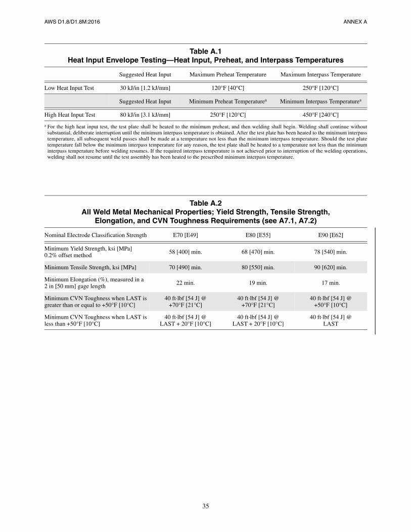
35
AWS D1.8/D1.8M:2016 ANNEX A
Table A.1Heat Input Envelope Testing—Heat Input, Preheat, and Interpass Temperatures
Suggested Heat Input Maximum Preheat Temperature Maximum Interpass Temperature
Low Heat Input Test 30 kJ/in [1.2 kJ/mm] 120°F [40°C] 250°F [120°C]
Suggested Heat Input Minimum Preheat Temperaturea Minimum Interpass Temperaturea
High Heat Input Test 80 kJ/in [3.1 kJ/mm] 250°F [120°C] 450°F [240°C]
a For the high heat input test, the test plate shall be heated to the minimum preheat, and then welding shall begin. Welding shall continue withoutsubstantial, deliberate interruption until the minimum interpass temperature is obtained. After the test plate has been heated to the minimum interpasstemperature, all subsequent weld passes shall be made at a temperature not less than the minimum interpass temperature. Should the test platetemperature fall below the minimum interpass temperature for any reason, the test plate shall be heated to a temperature not less than the minimuminterpass temperature before welding resumes. If the required interpass temperature is not achieved prior to interruption of the welding operations,welding shall not resume until the test assembly has been heated to the prescribed minimum interpass temperature.
Table A.2All Weld Metal Mechanical Properties; Yield Strength, Tensile Strength,
Elongation, and CVN Toughness Requirements (see A7.1, A7.2)
Nominal Electrode Classification Strength E70 [E49] E80 [E55] E90 [E62]
Minimum Yield Strength, ksi [MPa]0.2% offset method 58 [400] min. 68 [470] min. 78 [540] min.
Minimum Tensile Strength, ksi [MPa] 70 [490] min. 80 [550] min. 90 [620] min.
Minimum Elongation (%), measured in a 2 in [50 mm] gage length 22 min. 19 min. 17 min.
Minimum CVN Toughness when LAST is greater than or equal to +50°F [10°C]
40 ft·lbf [54 J] @+70°F [21°C]
40 ft·lbf [54 J] @+70°F [21°C]
40 ft·lbf [54 J] @+50°F [10°C]
Minimum CVN Toughness when LAST is less than +50°F [10°C]
40 ft·lbf [54 J] @LAST + 20°F [10°C]
40 ft·lbf [54 J] @LAST + 20°F [10°C]
40 ft·lbf [54 J] @LAST
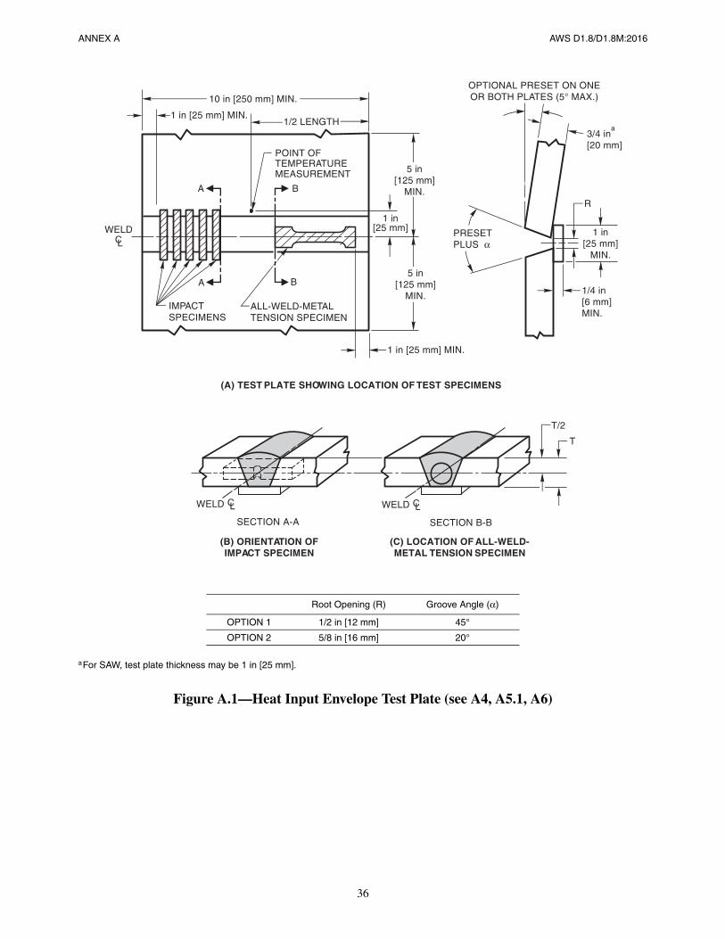
36
ANNEX A AWS D1.8/D1.8M:2016
aFor SAW, test plate thickness may be 1 in [25 mm].
Figure A.1—Heat Input Envelope Test Plate (see A4, A5.1, A6)
Root Opening (R) Groove Angle (α)
OPTION 1 1/2 in [12 mm] 45°
OPTION 2 5/8 in [16 mm] 20°
IMPACTSPECIMENS
(A) TEST PLATE SHOWING LOCATION OF TEST SPECIMENS
PRESETPLUS α
R
3/4 in[20 mm]
5 in[125 mm]
MIN.
T/2
1/4 in[6 mm]MIN.
1 in [25 mm] MIN.
(B) ORIENTATION OFIMPACT SPECIMEN
(C) LOCATION OF ALL-WELD-METAL TENSION SPECIMEN
1 in [25 mm] MIN.
10 in [250 mm] MIN.
POINT OFTEMPERATUREMEASUREMENT
ALL-WELD-METALTENSION SPECIMEN
1/2 LENGTH
1 in[25 mm]
A
A
B
B
WELD CL
CWELD L
SECTION A-A
CWELD L
SECTION B-B
OPTIONAL PRESET ON ONEOR BOTH PLATES (5° MAX.)
5 in[125 mm]
MIN.
1 in[25 mm]
MIN.
T
a
AWS D1.8/D1.8M:2016
37
Annex B (Normative)
Intermix CVN Testing of Filler Metal Combinations(where one of the filler metals is FCAW-S)
This annex is part of this standard and includes mandatory elements for use with this standard.
B1. Purpose
This annex provides testing procedures used to determine the suitability of combining FCAW-S with other welding pro-cesses in a single joint. The testing as required by this annex may be performed by the filler metal manufacturer, theContractor, or an independent testing agency.
B2. Filler Metal Variables
Filler metal essential variables for the intermix CVN testing shall be as summarized in Tables B.1 and B.2. Changes inthese essential variables shall require an additional test.
B3. Test Plate Details
A single test plate of ASTM A36, A572 Grade 50, or A992 shall be used to evaluate E70 [E49] filler metal combina-tions, and ASTM A572 Grade 65 or A913 Grade 65 shall be used to evaluate E80 [E55] filler metal combinations. A913Grade 70 shall be used to evaluate E90 [E62] filler metal combinations. The test plate shall be 3/4 in [20 mm] thick, witheither a 5/8 in [16 mm] root opening with a 20° included groove angle, or a 1/2 in [12 mm] root opening with a 45°included groove angle. The test plate and specimens shall be as shown in Figure B.1. Alternatively, a PQR test plate maybe used in accordance with 6.1.4(2).
B4. Welding of Test Plate
The sequence of placement of weld metals shall be the same as that to be employed in production. The first materialshall be known as the substrate/root material, and the subsequent material shall be known as the fill material. Approxi-mately one-third the thickness of the test joint shall be welded with the substrate/root material. The balance of the jointshall be welded with the fill material.
B5. Test Specimens Required
Five or ten CVN test specimens shall be made from the test plate, depending on the required number of tests. CVN spec-imens shall be prepared in accordance with AWS B4.0, Standard Methods for Mechanical Testing of Welds, Clause A3.
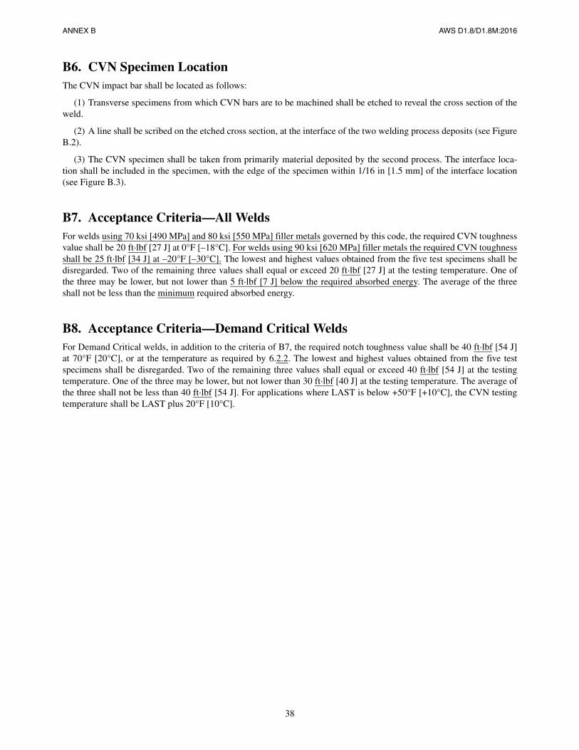
38
ANNEX B AWS D1.8/D1.8M:2016
B6. CVN Specimen LocationThe CVN impact bar shall be located as follows:
(1) Transverse specimens from which CVN bars are to be machined shall be etched to reveal the cross section of theweld.
(2) A line shall be scribed on the etched cross section, at the interface of the two welding process deposits (see FigureB.2).
(3) The CVN specimen shall be taken from primarily material deposited by the second process. The interface loca-tion shall be included in the specimen, with the edge of the specimen within 1/16 in [1.5 mm] of the interface location(see Figure B.3).
B7. Acceptance Criteria—All WeldsFor welds using 70 ksi [490 MPa] and 80 ksi [550 MPa] filler metals governed by this code, the required CVN toughnessvalue shall be 20 ft·lbf [27 J] at 0°F [–18°C]. For welds using 90 ksi [620 MPa] filler metals the required CVN toughnessshall be 25 ft·lbf [34 J] at –20°F [–30°C]. The lowest and highest values obtained from the five test specimens shall bedisregarded. Two of the remaining three values shall equal or exceed 20 ft·lbf [27 J] at the testing temperature. One ofthe three may be lower, but not lower than 5 ft·lbf [7 J] below the required absorbed energy. The average of the threeshall not be less than the minimum required absorbed energy.
B8. Acceptance Criteria—Demand Critical WeldsFor Demand Critical welds, in addition to the criteria of B7, the required notch toughness value shall be 40 ft·lbf [54 J]at 70°F [20°C], or at the temperature as required by 6.2.2. The lowest and highest values obtained from the five testspecimens shall be disregarded. Two of the remaining three values shall equal or exceed 40 ft·lbf [54 J] at the testingtemperature. One of the three may be lower, but not lower than 30 ft·lbf [40 J] at the testing temperature. The average ofthe three shall not be less than 40 ft·lbf [54 J]. For applications where LAST is below +50°F [+10°C], the CVN testingtemperature shall be LAST plus 20°F [10°C].
39
AWS D1.8/D1.8M:2016 ANNEX B
Table B.1Filler Metal Essential Variables—FCAW-S Substrate/Root
Substrate/Root Fill
FCAW-S FCAW-S FCAW-G SMAW GMAW SAW Other
AWS Classification X X X X X X
Manufacturer X X X X X
Manufacturer’s Brand and Trade Name X X X X X
Diameter X X X X X
Note: An “X” in the column indicates that the essential variable is applicable for the particular welding process and weld type.
Table B.2Filler Metal Essential Variables—FCAW-S Fill
Substrate/Root Fill
FCAW-S FCAW-G SMAW GMAW SAW Other FCAW-S
AWS Classification X X X X X X
Manufacturer X X X X X
Manufacturer’s Brand and Trade Name X X X X
Diameter X
Note: An “X” in the column indicates that the essential variable is applicable for the particular welding process and weld type.
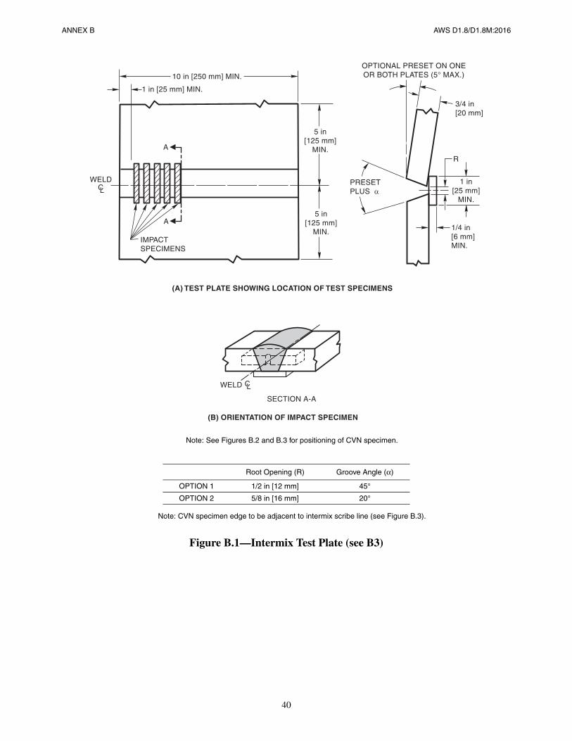
40
ANNEX B AWS D1.8/D1.8M:2016
Note: See Figures B.2 and B.3 for positioning of CVN specimen.
Note: CVN specimen edge to be adjacent to intermix scribe line (see Figure B.3).
Figure B.1—Intermix Test Plate (see B3)
Root Opening (R) Groove Angle (α)
OPTION 1 1/2 in [12 mm] 45°
OPTION 2 5/8 in [16 mm] 20°
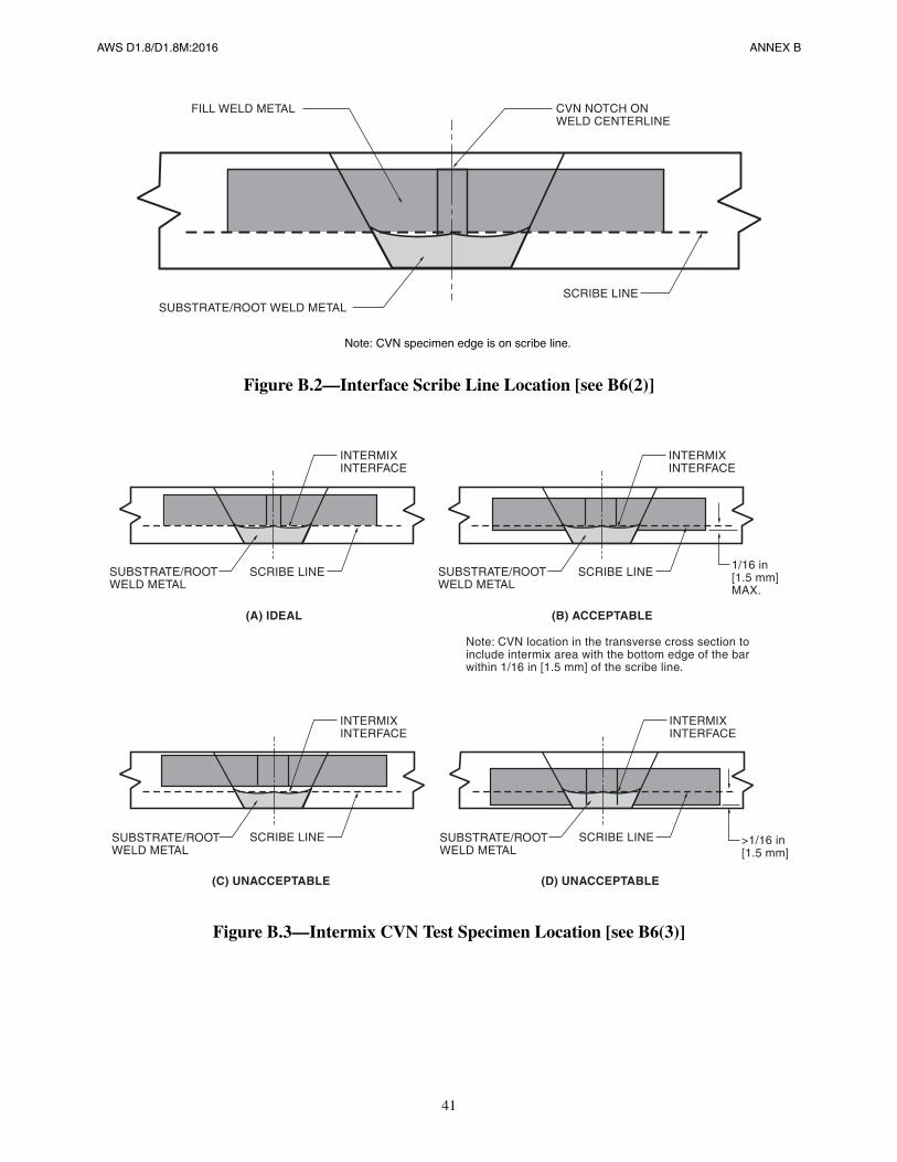
41
AWS D1.8/D1.8M:2016 ANNEX B
Note: CVN specimen edge is on scribe line.
Figure B.2—Interface Scribe Line Location [see B6(2)]
Figure B.3—Intermix CVN Test Specimen Location [see B6(3)]
CVN NOTCH ONWELD CENTERLINE
SCRIBE LINESUBSTRATE/ROOT WELD METAL
FILL WELD METAL
INTERMIXINTERFACE
SCRIBE LINESUBSTRATE/ROOTWELD METAL
(A) IDEAL
INTERMIXINTERFACE
SCRIBE LINE
(B) ACCEPTABLE
1/16 in[1.5 mm]MAX.
Note: CVN location in the transverse cross section toinclude intermix area with the bottom edge of the barwithin 1/16 in [1.5 mm] of the scribe line.
INTERMIXINTERFACE
SCRIBE LINE
(C) UNACCEPTABLE
INTERMIXINTERFACE
SCRIBE LINE
(D) UNACCEPTABLE
SUBSTRATE/ROOTWELD METAL
SUBSTRATE/ROOTWELD METAL
SUBSTRATE/ROOTWELD METAL
>1/16 in[1.5 mm]

This page is intentionally blank.
AWS D1.8/D1.8M:2016
42
AWS D1.8/D1.8M:2016
43
Annex C
There is no Annex C. Annex C has been omitted in order to avoid potential confusion with references to Commentary clauses.

This page is intentionally blank.
AWS D1.8/D1.8M:2016
44
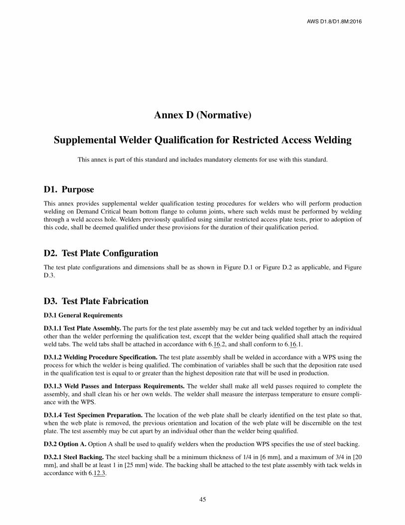
AWS D1.8/D1.8M:2016
45
Annex D (Normative)
Supplemental Welder Qualification for Restricted Access Welding
This annex is part of this standard and includes mandatory elements for use with this standard.
D1. PurposeThis annex provides supplemental welder qualification testing procedures for welders who will perform productionwelding on Demand Critical beam bottom flange to column joints, where such welds must be performed by weldingthrough a weld access hole. Welders previously qualified using similar restricted access plate tests, prior to adoption ofthis code, shall be deemed qualified under these provisions for the duration of their qualification period.
D2. Test Plate ConfigurationThe test plate configurations and dimensions shall be as shown in Figure D.1 or Figure D.2 as applicable, and FigureD.3.
D3. Test Plate FabricationD3.1 General Requirements
D3.1.1 Test Plate Assembly. The parts for the test plate assembly may be cut and tack welded together by an individualother than the welder performing the qualification test, except that the welder being qualified shall attach the requiredweld tabs. The weld tabs shall be attached in accordance with 6.16.2, and shall conform to 6.16.1.
D3.1.2 Welding Procedure Specification. The test plate assembly shall be welded in accordance with a WPS using theprocess for which the welder is being qualified. The combination of variables shall be such that the deposition rate usedin the qualification test is equal to or greater than the highest deposition rate that will be used in production.
D3.1.3 Weld Passes and Interpass Requirements. The welder shall make all weld passes required to complete theassembly, and shall clean his or her own welds. The welder shall measure the interpass temperature to ensure compli-ance with the WPS.
D3.1.4 Test Specimen Preparation. The location of the web plate shall be clearly identified on the test plate so that,when the web plate is removed, the previous orientation and location of the web plate will be discernible on the testplate. The test assembly may be cut apart by an individual other than the welder being qualified.
D3.2 Option A. Option A shall be used to qualify welders when the production WPS specifies the use of steel backing.
D3.2.1 Steel Backing. The steel backing shall be a minimum thickness of 1/4 in [6 mm], and a maximum of 3/4 in [20mm], and shall be at least 1 in [25 mm] wide. The backing shall be attached to the test plate assembly with tack welds inaccordance with 6.12.3.
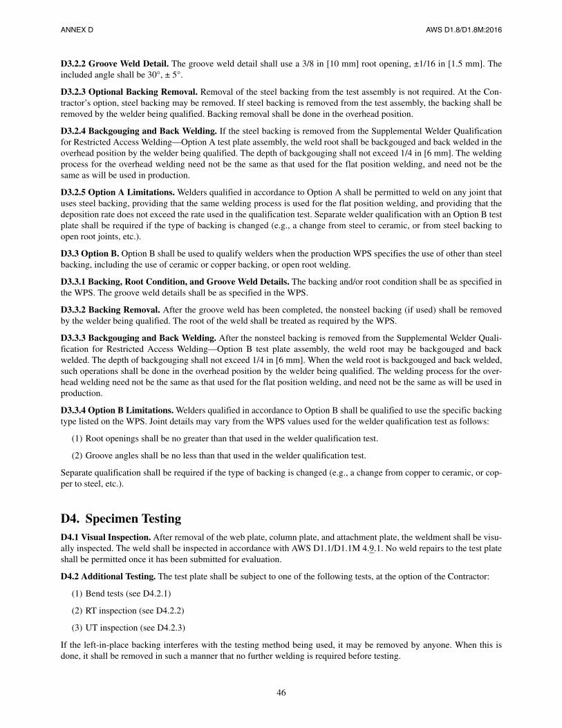
46
ANNEX D AWS D1.8/D1.8M:2016
D3.2.2 Groove Weld Detail. The groove weld detail shall use a 3/8 in [10 mm] root opening, ±1/16 in [1.5 mm]. Theincluded angle shall be 30°, ± 5°.
D3.2.3 Optional Backing Removal. Removal of the steel backing from the test assembly is not required. At the Con-tractor’s option, steel backing may be removed. If steel backing is removed from the test assembly, the backing shall beremoved by the welder being qualified. Backing removal shall be done in the overhead position.
D3.2.4 Backgouging and Back Welding. If the steel backing is removed from the Supplemental Welder Qualificationfor Restricted Access Welding—Option A test plate assembly, the weld root shall be backgouged and back welded in theoverhead position by the welder being qualified. The depth of backgouging shall not exceed 1/4 in [6 mm]. The weldingprocess for the overhead welding need not be the same as that used for the flat position welding, and need not be thesame as will be used in production.
D3.2.5 Option A Limitations. Welders qualified in accordance to Option A shall be permitted to weld on any joint thatuses steel backing, providing that the same welding process is used for the flat position welding, and providing that thedeposition rate does not exceed the rate used in the qualification test. Separate welder qualification with an Option B testplate shall be required if the type of backing is changed (e.g., a change from steel to ceramic, or from steel backing toopen root joints, etc.).
D3.3 Option B. Option B shall be used to qualify welders when the production WPS specifies the use of other than steelbacking, including the use of ceramic or copper backing, or open root welding.
D3.3.1 Backing, Root Condition, and Groove Weld Details. The backing and/or root condition shall be as specified inthe WPS. The groove weld details shall be as specified in the WPS.
D3.3.2 Backing Removal. After the groove weld has been completed, the nonsteel backing (if used) shall be removedby the welder being qualified. The root of the weld shall be treated as required by the WPS.
D3.3.3 Backgouging and Back Welding. After the nonsteel backing is removed from the Supplemental Welder Quali-fication for Restricted Access Welding—Option B test plate assembly, the weld root may be backgouged and backwelded. The depth of backgouging shall not exceed 1/4 in [6 mm]. When the weld root is backgouged and back welded,such operations shall be done in the overhead position by the welder being qualified. The welding process for the over-head welding need not be the same as that used for the flat position welding, and need not be the same as will be used inproduction.
D3.3.4 Option B Limitations. Welders qualified in accordance to Option B shall be qualified to use the specific backingtype listed on the WPS. Joint details may vary from the WPS values used for the welder qualification test as follows:
(1) Root openings shall be no greater than that used in the welder qualification test.
(2) Groove angles shall be no less than that used in the welder qualification test.
Separate qualification shall be required if the type of backing is changed (e.g., a change from copper to ceramic, or cop-per to steel, etc.).
D4. Specimen TestingD4.1 Visual Inspection. After removal of the web plate, column plate, and attachment plate, the weldment shall be visu-ally inspected. The weld shall be inspected in accordance with AWS D1.1/D1.1M 4.9.1. No weld repairs to the test plateshall be permitted once it has been submitted for evaluation.
D4.2 Additional Testing. The test plate shall be subject to one of the following tests, at the option of the Contractor:
(1) Bend tests (see D4.2.1)
(2) RT inspection (see D4.2.2)
(3) UT inspection (see D4.2.3)
If the left-in-place backing interferes with the testing method being used, it may be removed by anyone. When this isdone, it shall be removed in such a manner that no further welding is required before testing.
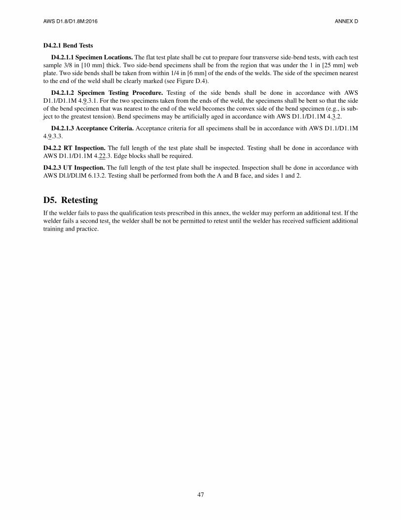
AWS D1.8/D1.8M:2016 ANNEX D
47
D4.2.1 Bend Tests
D4.2.1.1 Specimen Locations. The flat test plate shall be cut to prepare four transverse side-bend tests, with each testsample 3/8 in [10 mm] thick. Two side-bend specimens shall be from the region that was under the 1 in [25 mm] webplate. Two side bends shall be taken from within 1/4 in [6 mm] of the ends of the welds. The side of the specimen nearestto the end of the weld shall be clearly marked (see Figure D.4).
D4.2.1.2 Specimen Testing Procedure. Testing of the side bends shall be done in accordance with AWSD1.1/D1.1M 4.9.3.1. For the two specimens taken from the ends of the weld, the specimens shall be bent so that the sideof the bend specimen that was nearest to the end of the weld becomes the convex side of the bend specimen (e.g., is sub-ject to the greatest tension). Bend specimens may be artificially aged in accordance with AWS D1.1/D1.1M 4.3.2.
D4.2.1.3 Acceptance Criteria. Acceptance criteria for all specimens shall be in accordance with AWS D1.1/D1.1M4.9.3.3.
D4.2.2 RT Inspection. The full length of the test plate shall be inspected. Testing shall be done in accordance withAWS D1.1/D1.1M 4.22.3. Edge blocks shall be required.
D4.2.3 UT Inspection. The full length of the test plate shall be inspected. Inspection shall be done in accordance withAWS Dl.l/Dl.lM 6.13.2. Testing shall be performed from both the A and B face, and sides 1 and 2.
D5. RetestingIf the welder fails to pass the qualification tests prescribed in this annex, the welder may perform an additional test. If thewelder fails a second test, the welder shall be not be permitted to retest until the welder has received sufficient additionaltraining and practice.
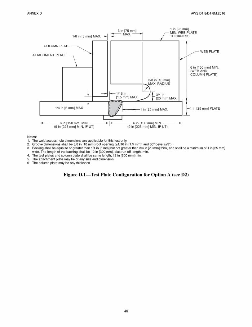
48
ANNEX D AWS D1.8/D1.8M:2016
Notes:1. The weld access hole dimensions are applicable for this test only.2. Groove dimensions shall be 3/8 in [10 mm] root opening (±1/16 in [1.5 mm]) and 30° bevel (±5°).3. Backing shall be equal to or greater than 1/4 in [6 mm] but not greater than 3/4 in [20 mm] thick, and shall be a minimum of 1 in [25 mm]
wide. The length of the backing shall be 12 in [300 mm], plus run off length, min.4. The test plates and column plate shall be same length, 12 in [300 mm] min.5. The attachment plate may be of any size and dimension.6. The column plate may be any thickness.
Figure D.1—Test Plate Configuration for Option A (see D2)
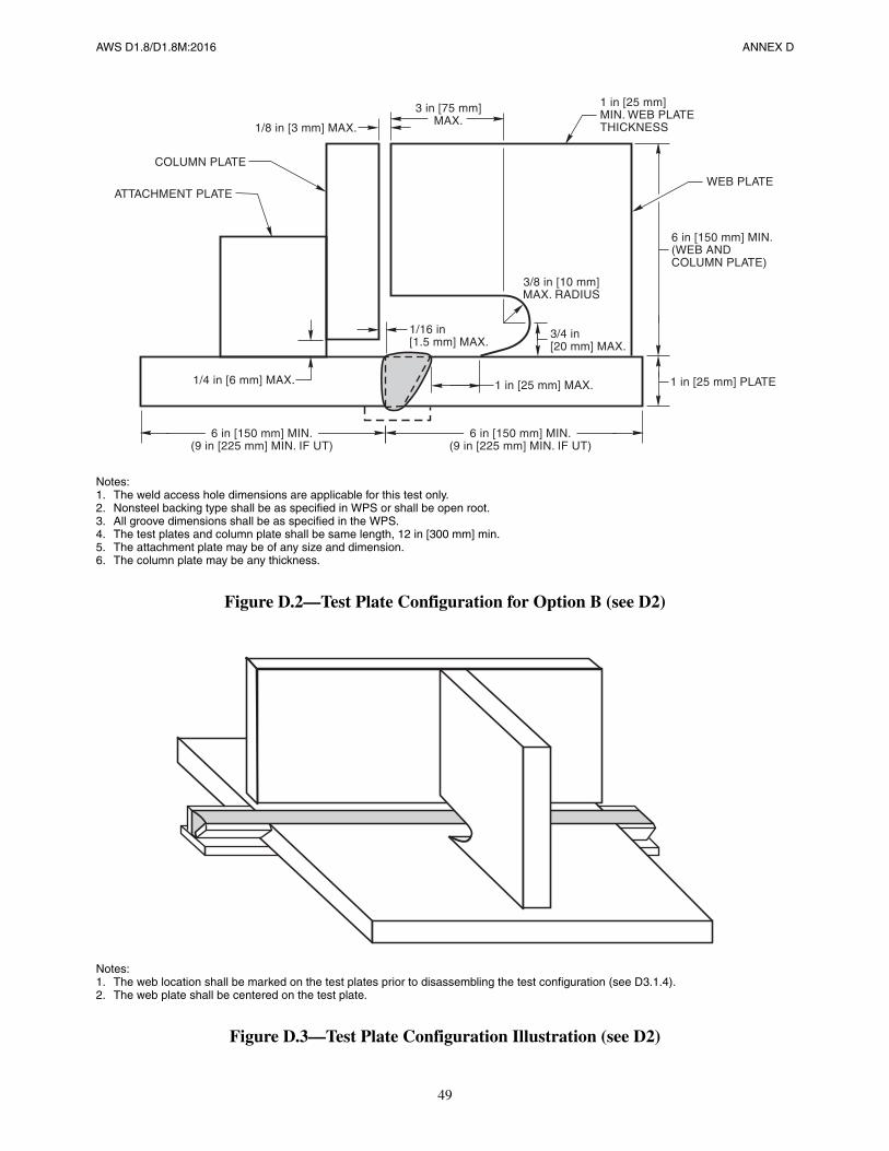
49
AWS D1.8/D1.8M:2016 ANNEX D
Notes:1. The weld access hole dimensions are applicable for this test only.2. Nonsteel backing type shall be as specified in WPS or shall be open root.3. All groove dimensions shall be as specified in the WPS.4. The test plates and column plate shall be same length, 12 in [300 mm] min.5. The attachment plate may be of any size and dimension.6. The column plate may be any thickness.
Figure D.2—Test Plate Configuration for Option B (see D2)
Notes:1. The web location shall be marked on the test plates prior to disassembling the test configuration (see D3.1.4).2. The web plate shall be centered on the test plate.
Figure D.3—Test Plate Configuration Illustration (see D2)
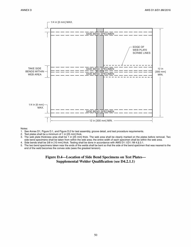
50
ANNEX D AWS D1.8/D1.8M:2016
Notes:1. See Annex D1, Figure D.1, and Figure D.2 for test assembly, groove detail, and test procedure requirements.2. Test plates shall be a minimum of 1 in [25 mm] thick.3. The web plate thickness area shall be 1 in [25 mm] thick. The web area shall be clearly marked on the plates before removal. Two
side bend specimens shall be taken from within the web area; the entire width of each specimen shall be within the web area.4. Side bends shall be 3/8 in [10 mm] thick. Testing shall be done in accordance with AWS D1.1/D1.1M 4.9.3.1.5. The two bend specimens taken near the ends of the welds shall be bent so that the side of the bend specimen that was nearest to the
end of the weld becomes the convex side (sees the greatest tension).
Figure D.4—Location of Side Bend Specimens on Test Plates—Supplemental Welder Qualification (see D4.2.1.1)
TAKE SIDEBENDS WITHIN
WEB AREA
1/4 in [6 mm]MAX.
12 in [300 mm] MIN.
SIDE BEND SPECIMEN
EDGE OFWEB PLATESCRIBE LINES
1/4 in [6 mm] MAX.
12 in[300 mm]
MIN.
SIDE BEND SPECIMEN
SIDE BEND SPECIMEN
SIDE BEND SPECIMEN
AWS D1.8/D1.8M:2016
51
Annex E (Normative)
Supplemental Testing for ExtendedExposure Limits for FCAW Filler Metals
This annex is part of this standard and includes mandatory elements for use with this standard.
E1. PurposeThe supplemental testing prescribed in this annex shall be used when exposure periods in excess of 72 hours as permit-ted by 6.4.3(3) are to be utilized for FCAW electrodes.
E2. Test Exposure ConditionsThe electrode shall be exposed to an environment of 80°F (+5°F, –0°F) [27°C (+3°C, –0°C)] and 80% (+5%, –0%) rela-tive humidity for the period of time desired to be approved for accumulated exposure. The environmental chamber shallmeet the requirements of AWS A5.5/A5.5M:2006 subclause 16.4, except for 16.4(3). Exposure time shall begin whenthe environmental chamber has reached the required temperature and humidity. Time, temperature, and humidity shallbe continuously recorded for the period that the electrodes are in the chamber.
E3. Diffusible Hydrogen TestingE3.1 Electrode Conditioning Prior to Testing. No conditioning of electrode after exposure and prior to testing shall bepermitted.
E3.2 Testing Procedures. Testing for diffusible hydrogen levels shall be performed in accordance with AWSA5.20/A5.20M:2005 Clause 16, Diffusible Hydrogen Test, or AWS A5.36/A5.36M:2012 Clause 15, Diffusible Hydro-gen Test, except the electrode diameter shall be in accordance with one of the following options:
(1) Tests are performed with electrodes a diameter larger and a diameter smaller than that used in production.
(2) Tests are performed using the diameter of electrode to be used in production.
The electrodes shall be exposed to the environment as specified in Clause E2. The AWS A5.20/A5.20M:2005 or AWSA5.36/A5.36M provisions for “previously unopened containers” and for “as received condition” shall not apply. Theexposure conditions and period shall be stated on the test report.
E4. Exposure Limitation CriteriaE4.1 Qualification of Alternate Atmospheric Exposure Criteria. The electrode shall be approved for accumulatedatmospheric exposure longer than the default exposure time period of 72 hours provided the electrode, as tested in accor-
52
ANNEX E AWS D1.8/D1.8M:2016
dance with AWS A4.3, modified by the above restrictions, satisfies the maximum diffusible hydrogen requirements forH16 or less.
E4.2 Storage and Atmospheric Exposure. Based upon test results, the manufacturer of the electrode, or a consultantapproved by the Engineer for this purpose, shall provide recommendations for storage and atmospheric exposure toensure that the diffusible hydrogen level will not exceed H16. Such recommendations may take the form of fixed expo-sure periods, or specific exposure limits based upon different temperature and humidity conditions.
E4.3 Heating, Baking, and Rebaking. Provisions may also include requirements for heated storage and/or baking ofelectrode wires. Rebaking of wire shall be included only when approved by the electrode manufacturer and documentedby testing that, after the baking procedure, the wire has returned to a diffusible hydrogen of H16 or better.
AWS D1.8/D1.8M:2016
53
Annex F (Normative)
Supplemental Ultrasonic Technician Qualification
This annex is part of this standard and includes mandatory elements for use with this standard.
F1. Personnel
Ultrasonic testing (UT) personnel shall demonstrate proficiency by satisfactory performance in a qualification examina-tion as prescribed below.
F2. Examination
The examination shall consist of practical tests that have been developed by the NDT Agency’s UT Level III, or an orga-nization approved by the Agency, and shall incorporate the specific requirements of the NDT Agency’s procedures andthe applicable weld quality acceptance standards contained in 7.10.2. The examination shall utilize the UT procedure(s)of AWS D1.1/D1.1M Clause 6, Part F for Flaw Detection. Alternatively, when AWS D1.1/D1.1M Annex Q is to beused, the examination shall utilize the UT techniques of Annex Q, UT Techniques for Flaw Detection.
In addition to the above requirements, the examination shall also test the ability of UT personnel to correctly calibrateUT equipment and complete the relevant paperwork associated with the examination. Testing procedures and examina-tion results shall be documented and available to the Engineer for review.
F3. Test Specimens
F3.1 Geometry. The test specimens shall be representative of the details of typical welded joints, but need not duplicatethe exact conditions (thickness, width, skew, root opening, groove angle, grade of steel, etc.) that will be used on theactual project. The specimens shall be mockups of welded joints, with and without steel backing. Typical joint geometryusing butt and tee configurations shall be utilized.
F3.2 Material Imperfections. All test specimen materials shall be examined by longitudinal wave techniques to iden-tify the presence or absence of laminations and/or inclusions. Materials containing detected laminations shall not be usedfor test specimens where the laminations would preclude accurate weld testing. Materials containing these planar anom-alies may be intentionally incorporated into selected coupons to evaluate the candidate’s performance on these imperfec-tions.
F3.3 Discontinuities (Natural and Artificial). Test coupons shall contain natural discontinuities and/or artificial reflec-tors consisting of nonmetallic inserts in the weld deposit, or thin steel inserts fillet welded to bevel preparations to simu-late incomplete fusion. The size of discontinuities inserted or induced into the test coupons shall be consistent with therange of flaw size acceptance criteria set forth in this document.
54
ANNEX F AWS D1.8/D1.8M:2016
F3.4 Confirmation and Categorization of Flaws. After fabrication, test specimens shall be examined by RT or UT toconfirm the location and size of flaws. Two UT Level III Technicians shall agree that each reflector in the test plates isproperly categorized as defined herein.
F3.5 Number of Flaws. At least 20 flaws shall be used for the examination of each technician.
F3.6 Test Specimen Confidentiality. Information regarding the discontinuities used for an examination shall not bediscussed with the candidate prior to or following completion of the examination, if the test pieces are to be used for laterexaminations.
F3.7 Number of Test Plates. The 20 flaws shall be distributed over multiple test plates.
F4. Candidate Scoring for Flaw Detection
This shall apply for AWS D1.1/D1.1M Clause 6, Part F and for Annex Q, UT Techniques for Flaw Detection.
F4.1 Candidate Test Report. UT candidates shall submit a written report of all detected discontinuities found duringthe test piece examination. The report shall include each detected flaw, indication rating (decibels), size (length), loca-tion along the weld, and position within the weld cross section.
F4.2 Scoring Methodology and Formulas. An indication shall be considered a “detected flaw” if at least two of the fol-lowing attributes are correctly identified within the listed tolerances:
(1) Indication Rating within ±6 dB
(2) Indication Length within +1 in to –0.5 in [+25 mm to –12 mm]
(3) Indication Depth within ±0.25 in [±6 mm]
An indication shall be considered a “false indication” if the flaw does not exist, but is reported.
The rate of flaws detected, based upon reporting of the flaw and its location, is:
D = detected flaws/total flaws
The rate of false indications, is:
F = false indications/total indications
The UT technician rating is:
R = 1/2 (1 + D – F)
To be qualified to perform flaw detection, the candidate shall achieve all of the following:
(1) An overall rating R of 0.90 or higher
(2) A detection rating D of 0.87 or higher
(3) A false indication rating F of 0.15 or less
F5. Period of Effectiveness
Previously qualified personnel shall be requalified when they have not performed UT of steel construction for a periodof 6 months or more.
AWS D1.8/D1.8M:2016
55
Annex G (Normative)
Supplemental Magnetic Particle Testing Procedures
This annex is part of this standard and includes mandatory elements for use with this standard.
G1. PurposeThe purpose of this annex is to improve the reliability of Magnetic Particle Testing (MT) to locate any surface breakingflaws such as cracks and incomplete fusion that should be readily detectable with the yoke method.
G2. Procedure QualificationWritten MT examination procedures shall be prepared, considering the geometry of the work to be inspected, yokeapplication, light levels, accessibility, safety, and other factors.
The following items shall be detailed in the written procedure:
(1) Type of weld to be examined
(2) Type of magnetizing equipment, including type of current employed
(3) Surface preparation
(4) Examination sequence
(5) Magnetization plan
(6) Magnetic particle type and color
(7) Interpretation of indications
(8) Acceptance criteria
(9) Reporting forms and procedures
G3. Visual InspectionPrior to MT, the weld shall be inspected visually for detection of imperfections. The inspected surface shall be cleanedwhere necessary.
G4. Surface ConditionThe surface shall be cleaned prior to MT by grinding, wire brushing, hand scraping, or a combination of these. Weldsshall be dry and free from foreign materials such as dirt, grease, rust, and excessive weld spatter.
56
ANNEX G AWS D1.8/D1.8M:2016
G5. MethodThe continuous method, using an AC or DC electromagnetic yoke (double-leg or single-leg configuration) with dry,white-light-visible magnetic particles, shall be used.
G6. YokeThe yoke shall be of the articulating-leg type. A single-leg yoke may be used in areas of tight access. Fixed-leg yokes arenot permitted. AC yokes shall have a lifting force of at least 10 lbs [4.5 kg] and DC yokes shall have a minimum liftingforce of at least 40 lbs [18 kg] when the legs are spaced at the maximum inspection distance.
G7. MagnetizationA magnetizing current at 50 Hz to 60 Hz AC or DC electromagnetization shall be used for detection of surface-breakingdiscontinuities.
G8. ParticlesThe magnetic particles shall be dry, finely divided high-permeability ferromagnetic material with low retentivity and asuitable size range. Their color shall provide high contrast to the background on which applied. Particles shall be freefrom rust, fillers, or other material that could interfere with their use. Magnetic particle materials shall be used onlyonce. Particle application and removal equipment (powder bulbs, aerosol sprays) shall be such that fine indications arenot removed by excessive force.
G9. Equipment Performance ChecksThe performance of the magnetic particle inspection system and procedures shall be checked at regular intervals. Theyoke lifting force shall be checked each day, prior to performing any MT examination, and shall be documented.
G10. Yoke PlacementG10.1 Extent of Examination. Examination shall be conducted with sufficient overlap to ensure 100% coverage. How-ever, if the geometry of the piece does not permit 100% evaluation of the piece, this shall be stated on the test report.
G10.2 Detection of Longitudinal Discontinuities. For detection of longitudinal discontinuities, the yoke shall beplaced astride and approximately perpendicular to the weld. The yoke legs shall be positioned such that the weld isapproximately centered between the yoke legs. Sufficient overlap shall be used to ensure 100% coverage when movingalong the weld length. Subsequent yoke positions along the weld shall be a maximum of 1/2 of the yoke leg spacing(maximum inspection distance) or 3 in [75 mm], whichever is smaller.
G10.3 Detection of Transverse Discontinuities. For detection of transverse discontinuities, the yoke shall be orientedso that the yoke legs are approximately parallel to the weld, approximately 1/2 in [12 mm] from the toe of the weld. Ifthe yoke has to be placed on top of the weld to gain access, the technician shall ensure the best contact possible of theyoke legs to the weld.
G11. Particle Application and RemovalDry particles shall be applied in such a manner that a light, uniform, dustlike coating of particles settles on the part whileit is being magnetized. Particle indications shall be observed when being formed as the particles are being applied, andwhile the excess particles are being removed.
AWS D1.8/D1.8M:2016 ANNEX G
57
Sufficient air velocity for particle removal shall be directed at the area of inspection to remove the excess particlesentrapped in areas such as weld undercut, while retaining the particles held primarily by magnetic flux leakage from thediscontinuities.
G12. Interpretation and Evaluation of IndicationsRelevant MT indications shall be defined as those that result from magnetic flux leakage fields formed by discontinuitiesthat attract and hold magnetic particles.
Testing personnel shall verify indications by performing the following steps:
(1) Retest with the yoke field perpendicular to the discontinuity indication, if not already perpendicular.
(2) Retest, confirming that excess particles are removed. If the suspect indication is removed during the retest, theindication is interpreted as nonrelevant or as a false indication.
(3) If the indication has a light particle buildup and weak particle adhesion, and if doubt exists as to whether the indi-cation is relevant or false, the area of the indication shall be lightly surface-ground and retested.
G13. Acceptance CriteriaAll relevant indications, determined by MT to be cracks or incomplete fusion, shall be unacceptable, regardless oflength.
This page is intentionally blank.
AWS D1.8/D1.8M:2016
58
AWS D1.8/D1.8M:2016
59
Annex H (Normative)
Flaw Sizing by Ultrasonic Testing
This annex is part of this standard and includes mandatory elements for use with this standard.
H1. Flaw Sizing
When flaw sizing techniques are implemented, ultrasonic testing and UT technician qualification shall be performed fol-lowing written procedures as required by AWS D1.1/D1.1M Annex Q. Acceptance criteria shall be in accordance withthis clause.
H2. Acceptance Criteria
H2.1 Near-Surface Flaws. If a flaw is at or within 1/8 in [3 mm] of the surface, it shall be rejected and repaired orremoved.
H2.2 Embedded Flaw Height. Embedded flaws, defined as those that do not come within 1/8 in [3 mm] of the surface,shall be rejected if their height exceeds 1/4 in [6 mm].
H2.3 Flaws at Steel Backing. When steel backing remains in place, the size of flaws that extend into the weld metalshall be determined. Flaws that extend more than 1/8 in [3 mm] into the thickness of the groove weld shall be rejected.
H2.4 Embedded Flaw Area. Embedded flaws shall be rejected if their area, calculated by multiplying the maximumdiscontinuity height by the maximum discontinuity length, exceeds the square of the effective weld throat. Embeddedflaws, either individually or as a group within a length of weld 12 in [300 mm] or less, shall be rejected if they exceed atotal area (the sum of the areas of individual discontinuities) equal to 10% of the effective weld throat multiplied by theweld length. The weld length used for this calculation shall not exceed 12 in [300 mm], with longer welds being evalu-ated in multiple parts. Discontinuity height and length shall be measured perpendicular to the direction of principalstress.
H2.5 Aligned Discontinuities. Aligned discontinuities of lengths L1 and L2, separated by less than (L1+L2)/2 shall beevaluated as continuous.
H2.6 Parallel Discontinuities. Parallel discontinuities of heights H1 and H2, separated by less than (H1+H2)/2 shall beevaluated as continuous.
H3. UT Technician Qualification for Flaw Sizing
H3.1 Personnel. Ultrasonic testing (UT) personnel shall be qualified in accordance with Annex F and shall demonstrateproficiency by satisfactory performance in an examination as prescribed in H3.2.
60
ANNEX H AWS D1.8/D1.8M:2016
H3.2 Examination. The examination shall consist of practical tests that have been developed by the NDT Agency’s UTLevel III, or an organization approved by the Agency, and shall incorporate the specific requirements of the NDTAgency’s procedures and the applicable weld quality acceptance standards contained in Clause H2. The examinationshall utilize a UT procedure(s) that conforms to AWS D1.1/D1.1M Annex Q for flaw sizing.
The examination shall also test the ability of UT personnel to correctly calibrate UT equipment and complete the rele-vant paperwork associated with the examination. Testing procedures and examination results shall be documented andavailable to the Engineer for review.
AWS D1.8/D1.8M:2016
61
Annex I (Informative)
Requesting an Official Interpretation on an AWS Standard
This annex is not part of this standard but is included for informational purposes only.
I1. IntroductionThe following procedures are here to assist standard users in submitting successful requests for official interpretations toAWS standards. Requests from the general public submitted to AWS staff or committee members that do not followthese rules may be returned to the sender unanswered. AWS reserves the right to decline answering specific requests; ifAWS declines a request, AWS will provide the reason to the individual why the request was declined.
I2. LimitationsThe activities of AWS technical committees regarding interpretations are limited strictly to the interpretation of provi-sions of standards prepared by the committees. Neither AWS staff nor the committees are in a position to offer interpre-tive or consulting services on (1) specific engineering problems, (2) requirements of standards applied to fabricationsoutside the scope of the document, or (3) points not specifically covered by the standard. In such cases, the inquirershould seek assistance from a competent engineer experienced in the particular field of interest.
I3. General Procedure for all RequestsI3.1 Submission. All requests shall be sent to the Managing Director of AWS Technical Services Division. For efficienthandling, it is preferred that all requests should be submitted electronically through [email protected]. Alternatively,requests may be mailed to:
Managing DirectorTechnical Services DivisionAmerican Welding Society8669 NW 36 St, # 130Miami, FL 33166
I3.2 Contact Information. All inquiries shall contain the name, address, email, phone number, and employer of theinquirer.
I3.3 Scope. Each inquiry shall address one single provision of the standard unless the issue in question involves two ormore interrelated provisions. The provision(s) shall be identified in the scope of the request along with the edition of thestandard (e.g., D1.1:2006) that contains the provision(s) the inquirer is addressing.
I3.4 Question(s). All requests shall be stated in the form of a question that can be answered ‘yes’ or ‘no’. The requestshall be concise, yet complete enough to enable the committee to understand the point of the issue in question. When the
62
ANNEX I AWS D1.8/D1.8M:2016
point is not clearly defined, the request will be returned for clarification. Sketches should be used whenever appropriate,and all paragraphs, figures, and tables (or annexes) that bear on the issue in question shall be cited.
I3.5 Proposed Answer(s). The inquirer shall provide proposed answer(s) to their own question(s).
I3.6 Background. Additional information on the topic may be provided but is not necessary. The question(s) and pro-posed answer(s) above shall stand on their own without the need for additional background information.
I4. AWS Policy on InterpretationsThe American Welding Society (AWS) Board of Directors has adopted a policy whereby all official interpretations ofAWS standards are handled in a formal manner. Under this policy, all official interpretations are approved by the techni-cal committee that is responsible for the standard. Communication concerning an official interpretation is directedthrough the AWS staff member who works with that technical committee. The policy requires that all requests for anofficial interpretation be submitted in writing. Such requests will be handled as expeditiously as possible, but due to theprocedures that must be followed, some requests for an official interpretation may take considerable time to complete.
I5. AWS Response to Requests.Upon approval by the committee, the interpretation is an official interpretation of the Society, and AWS shall transmitthe response to the inquirer, publish it in the Welding Journal, and post it on the AWS website.
I6. Telephone InquiriesTelephone inquiries to AWS Headquarters concerning AWS standards should be limited to questions of a general natureor to matters directly related to the use of the standard. The AWS Board Policy Manual requires that all AWS staff mem-bers respond to a telephone request for an official interpretation of any AWS standard with the information that such aninterpretation can be obtained only through a written request. Headquarters staff cannot provide consulting services.However, the staff can refer a caller to any of those consultants whose names are on file at AWS Headquarters.
AWS D1.8/D1.8M:2016
63
Annex J (Informative)
Informative References
This annex is not part of this standard but is included for informational purposes only.
American Welding Society (AWS) standard:
(1) ANSI Z49.1, Safety in Welding, Cutting, and Allied Processes

This page is intentionally blank.
AWS D1.8/D1.8M:2016
64
AWS D1.8/D1.8M:2016
65
Commentary on
Structural Welding Code—
Seismic Supplement
3rd Edition
Prepared by theAWS D1 Committee on Structural Welding
Under the Direction of theAWS Technical Activities Committee
Approved by theAWS Board of Directors

This page is intentionally blank.
AWS D1.8/D1.8M:2016
66
AWS D1.8/D1.8M:2016 COMMENTARY
67
ForewordThis foreword is not part of this standard but is included for informational purposes only.
This commentary on AWS D1.8/D1.8M:2016 has been prepared to generate better understanding in the application ofthe code to welded construction of steel in seismic applications. Since the code is written in the form of a specification,it cannot present background material or discuss the Structural Welding Committee’s intent; it is the function of thiscommentary to fill this need.

This page is intentionally blank.
AWS D1.8/D1.8M:2016
68
AWS D1.8/D1.8M:2016
69
Commentary on
Structural Welding Code—Seismic Supplement
C-1. General Requirements
C-1.1 Scope
This code is typically applicable to welded joints in Seismic Force Resisting Systems designed in accordance with theAISC Seismic Provisions. This code is not intended to be applicable to the design or construction of steel structures, orportions of steel structures, not designed in accordance with the AISC Seismic Provisions.
These provisions are intended to apply only to joints or members that are likely to experience yield level stresses orstrains during a design seismic event, or whose failure would likely have a significant adverse impact on the perfor-mance of the Seismic Force Resisting System (SFRS). This will typically not include all welds on members of the SFRS.Subclause 1.4.1 requires the Engineer to clearly identify on the construction documents those welds that are subject tothe provisions of this standard.
The provisions of this code are intended to provide welded steel building structures with an ability to sustain the longterm and short term loadings specified by the building codes with adequate serviceability and reliability. Seismic loadsspecified by the building codes are quite different from other loading conditions in that there is an inherent assumptionthat, when subjected to a seismic event, the building structure’s Seismic Force Resisting Systems (SFRS) will undergosubstantial inelastic response. Depending on the type of SFRS present in a building, its configuration and detailing, thisinelastic response may result in inelastic straining of individual members of the SFRS or the connections of these mem-bers. The welded joints are detailed to resist yield strength level stresses while the connections and/or members areintended to yield away from the weld.
Damage sustained by welded steel moment-frame buildings in the 1994 Northridge earthquake, and extensive researchconducted by the FEMA SAC program following that earthquake demonstrated that in order to obtain adequate perfor-mance of welded steel structures under conditions of severe inelastic straining, additional controls on design, detailing,materials, workmanship, testing, and inspection are necessary. This research resulted in substantive changes to the AISCSeismic Provisions, which control the design of steel SFRS as well as certain aspects of the materials and detailing ofthese systems. The provisions contained in this standard complement the AISC Seismic Provisions and are intended toensure that welded joints that are designed to undergo significant repetitive inelastic strains as a result of earthquakes orthat are used to connect members designed to resist such inelastic strains have adequate strength, notch toughness, andintegrity to perform as intended. In general, the AISC Seismic Provisions specify the requirements for design of mem-bers, connections and welded joints in the SFRS. AISC Seismic Provisions also specify the requirements for a QualityAssurance Plan as well as the minimum levels of Quality Assurance that are appropriate for elements of the SFRS. Thiscode, together with AWS D1.1/D1.1M, specifies the acceptable materials, procedures and workmanship for constructingwelded joints in the SFRS as well as the procedures, and acceptance criteria for quality control and quality assuranceinspection of welded joints in the SFRS.
COMMENTARY AWS D1.8/D1.8M:2016
70
Structures designed for earthquake resistance are expected to dissipate earthquake energy through extensive reversing,repetitive, inelastic straining. This is the explicit assumption of the AISC Seismic Provisions, as well as that of the build-ing codes that reference these provisions.
This is a severe loading condition, which can result in development of fractures, unless proper proportioning of themembers, detailing of the connections, control of the materials of construction, and quality control of the fabrication anderection is exercised.
In research performed following the 1994 Northridge earthquake, it was determined that analytical evaluation of thebehavior of connections is not by itself sufficient to assure reliable behavior of structures subjected to these loading con-ditions. The 1997 and later editions of the AISC Seismic Provisions require that the performance capability of connec-tions of certain structural systems designed for severe seismic service be demonstrated (qualified) through combinedprograms of analytical work and testing. The AISC Seismic Provisions permit this qualification to be performed oneither a project-specific basis or on a more general prequalification basis. Regardless, reliable performance of thesestructures requires that the conditions of design, fabrication, and erection workmanship for which a connection wasqualified be maintained in the production work. For this to occur, 1.4.1 directs the Engineer to provide the needed infor-mation to the Fabricator and Erector through the Contract Documents.
C-1.4 ResponsibilitiesC-1.4.1 Engineer’s Responsibilities. This subclause provides a detailed list of information that the Engineer is respon-sible to provide as part of the Contract Documents in order to completely delineate the design intent related to weldedconnections in the SFRS. The information to be provided should reflect the requirements of this code, the AISC SeismicProvisions, and (when applicable) the AISC Prequalified Connections requirements.
It is intended that this code be used in conjunction with AISC Seismic Provisions, and AISC Connection Prequalifica-tion. In future editions of AISC Seismic Provisions, the AISC Prequalified Connections document, and this code, it isintended that overlapping requirements will be combined for consistency between the three documents. Where conflictsexist, the Engineer should coordinate and resolve the differences.
C-1.4.1 Items 2, 3, and 4. The AISC Seismic Provisions designate the members that are to be included in the SFRS, thedefinition of Protected Zones, and welds that are subject to special requirements beyond AWS D1.1/D1.1M (see FiguresC-1.1, C-1.2, and C-1.3).
C-1.4.1 Items 5, 6, and 7. The presence of backing, weld tabs, and welds between these attachments and the membersthey are attached to may affect the flow of stresses around the connections and contribute to stress concentrations.Therefore, the AISC Seismic Provisions and AISC Prequalified Connections based on the AISC Seismic Provisionsrequire the removal of these attachments in some locations. Some backing and tabs are in positions that make them diffi-cult to remove without damaging the adjacent material and test data demonstrates that acceptable performance can beachieved without their removal. Removal of backing and tabs, and the addition of reinforcing fillet welds, are details thatshould be evaluated on a joint specific basis. The AISC Seismic Provisions and connection qualifications and prequalifi-cations based on those provisions specify these requirements. In general, it is not necessary to remove backing and weldtabs unless so specified. It is the Engineer’s responsibility to incorporate in the Contract Documents all such require-ments. Table C-1.1 shows the frequently used practice for disposition of weld tabs and backing for some common con-nections. Specific details must be verified with governing documents.
C-1.4.1 Item 5. In addition to this code, both AISC Seismic Provisions and AISC Prequalified Connections providerequirements regarding steel backing removal. Backing removal may be impractical and unnecessary in locations suchas column splices. Backing removal is impossible at the inside corners of small box sections, and at column splices ofbox sections. Some AISC connection qualifications have been performed with backing remaining in place, thus removalis not justified for those applications. It is costly, and unnecessary, to require backing to be removed from all connec-tions (see C-6.13 and combined Commentary C-1.4.1 Items 5, 6, and 7).
C-1.4.1 Item 6. In addition to this code, both AISC Seismic Provisions and AISC Prequalified Connections providerequirements regarding where steel backing may remain in place, provided a fillet weld is applied to reduce the stressconcentration associated with the left-in-place backing. Analysis and testing has demonstrated that the naturally occur-ring unfused edge of steel backing that contacts the column face in a beam to column connection constitutes a severe
AWS D1.8/D1.8M:2016 COMMENTARY
71
stress raiser. By placing a fillet weld between the steel backing and the column face, this concentration can be signifi-cantly reduced. Contract Documents are required to show where this treatment of the backing is required (see 6.15, C-6.15, and combined Commentary C-1.4.1 Items 5, 6, and 7).
C-1.4.1 Item 7. In addition to this code, both AISC Seismic Provisions and AISC Prequalified Connections providerequirements regarding weld tab removal. Such removal may be impractical, or even harmful, in some situations. In gen-eral, weld tabs should not be used in the k-area, but if used, are best left in place rather than risking the damage thatmight occur during tab removal (see 6.16.3, 6.16.4, C-6.16.4, and combined Commentary C-1.4.1 Items 5, 6, and 7.
C-1.4.1 Item 8. In addition to this code, both AISC Seismic Provisions and AISC Prequalified Connections providerequirements regarding the use of reinforcing fillet welds. Such locations are typically in tee and corner joints, where theseismically induced loads are perpendicular to the weld axis, and where the reinforcing fillet weld, applied to a CJPgroove weld, reduces the stress concentration of a nearly 90° intersection between the weld face or root, and the adjacentsteel member. A typical location is at the groove weld to column face juncture of beam to column connections. Suchreinforcement is not required for most groove welds in tee or corner joints, and is not feasible for groove welds in buttjoints, such as column splices (also see 6.13 and C-6.14).
C-1.4.1 Item 9. In addition to this code, both AISC Seismic Provisions and AISC Prequalified Connections providerequirements regarding the use of access holes. Analysis and research have shown that the shape of the weld access holecan have a significant effect on the behavior of moment connections (see 6.11.1, 6.11.2, 6.11.3, and related commen-tary). The use of different weld access holes, other than that prescribed by AWS D1.1/D1.1M, has not been found neces-sary for locations such as column splices. Care should be exercised to avoid specifying special weld access holegeometries when not justified. In some situations, no weld access holes are desirable, such as in end plate connections.
C-1.4.1 Item 10. The majority of welded connection applications in buildings are in temperature controlled settings.Where connections are subjected to temperatures of less than 50°F [10°C] during service, additional requirements forthe weld consumables may be necessary to ensure adequate resistance to fracture at the lower service temperatures.
C-1.4.1 Item 11. The 2005 AISC Seismic Provisions provide requirements beyond AWS D1.1/D1.1M for welded buttjoints in column splices to provide for smoother flow of stresses through these critical joints.
C-1.4.1 Item 12. In common frame configurations, specific assembly order, welding sequence, welding technique, andother special precautions beyond those provided in this document should not be necessary. It is anticipated that suchadditional requirements will only be needed for special cases, such as those of unusually high restraint.
C-1.4.1 Item 13. A Quality Assurance Plan (QAP) is required by many Building Codes, the AISC Seismic Provisions,and AISC Prequalified Connections. The QAP is to be prepared by the Engineer, and is to be included as part of theContract Documents. It is essential that the QAP be provided to the Contractor as part of the bid documents as any spe-cial Quality Assurance or Quality Control requirements could have substantial impact on the cost of the work. Chapter Jof the AISC Seismic Provisions specifies the minimum acceptable requirements for a QAP that apply to the constructionof welded joints in the SFRS. The QAP as contained in Chapter J is recommended for adoption without unnecessaryrevision because consistent application of the same requirements is expected to improve reliability.
C-1.4.2.3 Product Data Sheets. The welding variables, storage, exposure, and baking (if applicable) recommenda-tions for FCAW and composite GMAW electrodes are product specific. It is important to obtain the manufacturer’s rec-ommendation regarding the relation between voltage and current for FCAW and composite GMAW electrodes. TheAWS D1.1/D1.1M tolerances are permitted to be applied to these recommended values, provided other requirements,such as heat input limitations, are met.
Variables such as amperage (or wire feed speed, if used), voltage, and electrode extension (also called “stickout”) aretypically supplied by filler metal manufacturers as these variables must be balanced in order to obtain acceptable weld-ing conditions. Travel speeds are directly dependent upon the weld type being made, and filler metal manufacturers donot typically supply this data.
For SMAW, only current is required to be controlled. The welding current recommendations for SMAW electrodes areproduct specific. The AWS D1.1/D1.1M requirements for exposure, storage, and baking are considered adequate forSMAW electrodes.
Solid wire electrodes for ESW, EGW, SAW, and GMAW are generic products that do not have manufacturer uniquevoltage and current characteristics. Some information on welding variables can be found in the AWS Welding Handbook.
COMMENTARY AWS D1.8/D1.8M:2016
72
Various other “how to” booklets, and procedure guides provide information on welding current and melting rates, volt-age adjustments, and some typical applications.
Solid wire electrodes do not have exposure limits or specific storage requirements other than to be kept clean and dry.Thus, some major manufacturers of solid wire electrodes do not provide recommendations for welding variables, expo-sure, and storage on the product data sheets.
C-1.4.2.4 Diffusible Hydrogen Content. See 6.1.3 and C-6.1.3. This supplement requires documentation for somebut not all filler metals. Exemptions are contained in 6.1.3. The documentation will typically be a Certificate of Con-formance. This provision does not require lot-specific hydrogen testing of the filler metal to be used.
C-1.4.2.5 Extended Exposure Capability of FCAW Filler Metals. Subclause 6.4.3 provides two bases forextended exposure of filler metals, both of which require testing of the filler metal in accordance with Annex E. Thisdocumentation will normally consist of a test report that records the testing conditions, and the measured diffusiblehydrogen level of welds made with the exposed electrode. This provision does not require lot-specific testing of the fillermetal to be used.
C-1.4.2.7 Supplemental Welder Qualification Testing Documentation. See Annex D and corresponding commentary.
C-1.5 LimitationsThese provisions have been developed based on tests and the historic usage of beams with minimum specified yieldstrengths of 55 ksi [380 MPa] or less. Plastic hinging in steel of this strength range has been extensively tested. Thiscode additionally covers applications where steels with minimum specified yield strengths of up to 70 ksi [490 MPa] arepermitted, although members made of such steels are not expected to contain the plastic hinge region (except perhaps forpanel zone yielding in columns). Such applications of steel with minimum specified yield strengths of 70 ksi [490 MPa]would include columns. The provisions within this code are not expected to be sufficient for design, fabrication, andinspection of structures made of steels that exceed these limits.
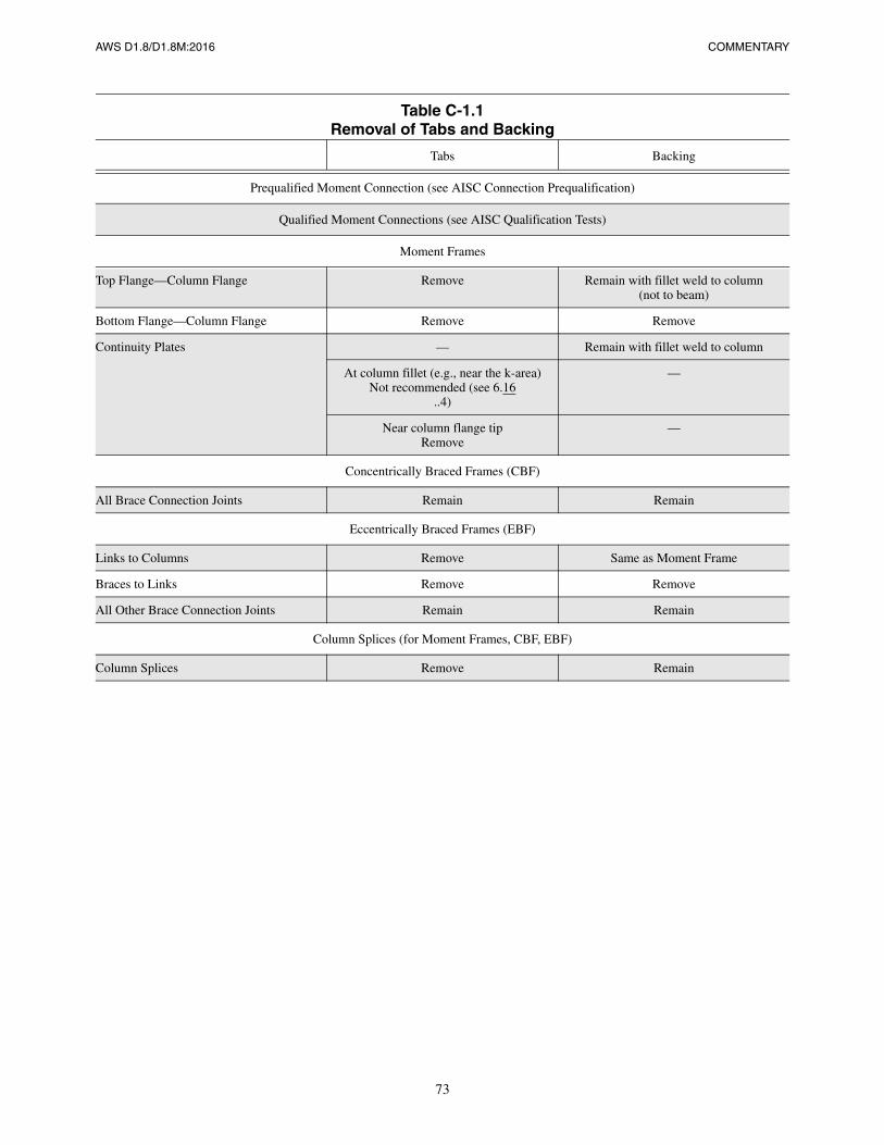
AWS D1.8/D1.8M:2016 COMMENTARY
73
Table C-1.1Removal of Tabs and Backing
Tabs Backing
Prequalified Moment Connection (see AISC Connection Prequalification)
Qualified Moment Connections (see AISC Qualification Tests)
Moment Frames
Top Flange—Column Flange Remove Remain with fillet weld to column(not to beam)
Bottom Flange—Column Flange Remove Remove
Continuity Plates — Remain with fillet weld to column
At column fillet (e.g., near the k-area)Not recommended (see 6.16
..4)
—
Near column flange tipRemove
—
Concentrically Braced Frames (CBF)
All Brace Connection Joints Remain Remain
Eccentrically Braced Frames (EBF)
Links to Columns Remove Same as Moment Frame
Braces to Links Remove Remove
All Other Brace Connection Joints Remain Remain
Column Splices (for Moment Frames, CBF, EBF)
Column Splices Remove Remain
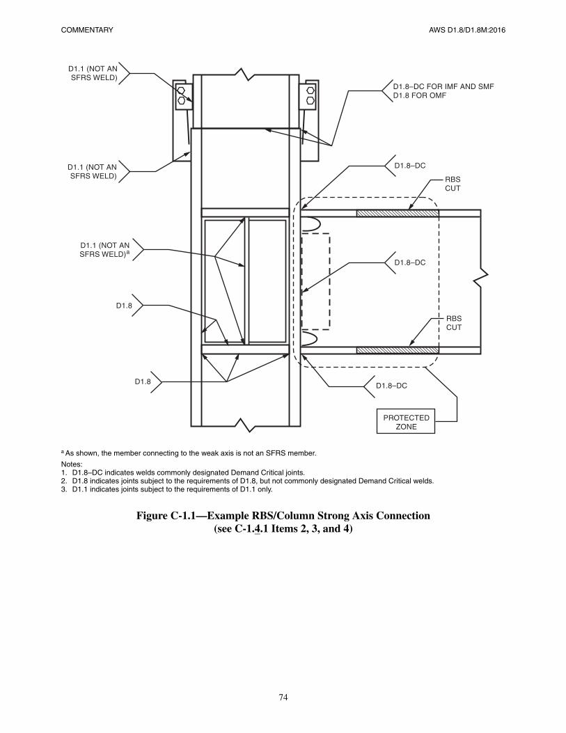
COMMENTARY AWS D1.8/D1.8M:2016
74
a As shown, the member connecting to the weak axis is not an SFRS member.
Notes:1. D1.8–DC indicates welds commonly designated Demand Critical joints.2. D1.8 indicates joints subject to the requirements of D1.8, but not commonly designated Demand Critical welds.3. D1.1 indicates joints subject to the requirements of D1.1 only.
Figure C-1.1—Example RBS/Column Strong Axis Connection(see C-1.4.1 Items 2, 3, and 4)
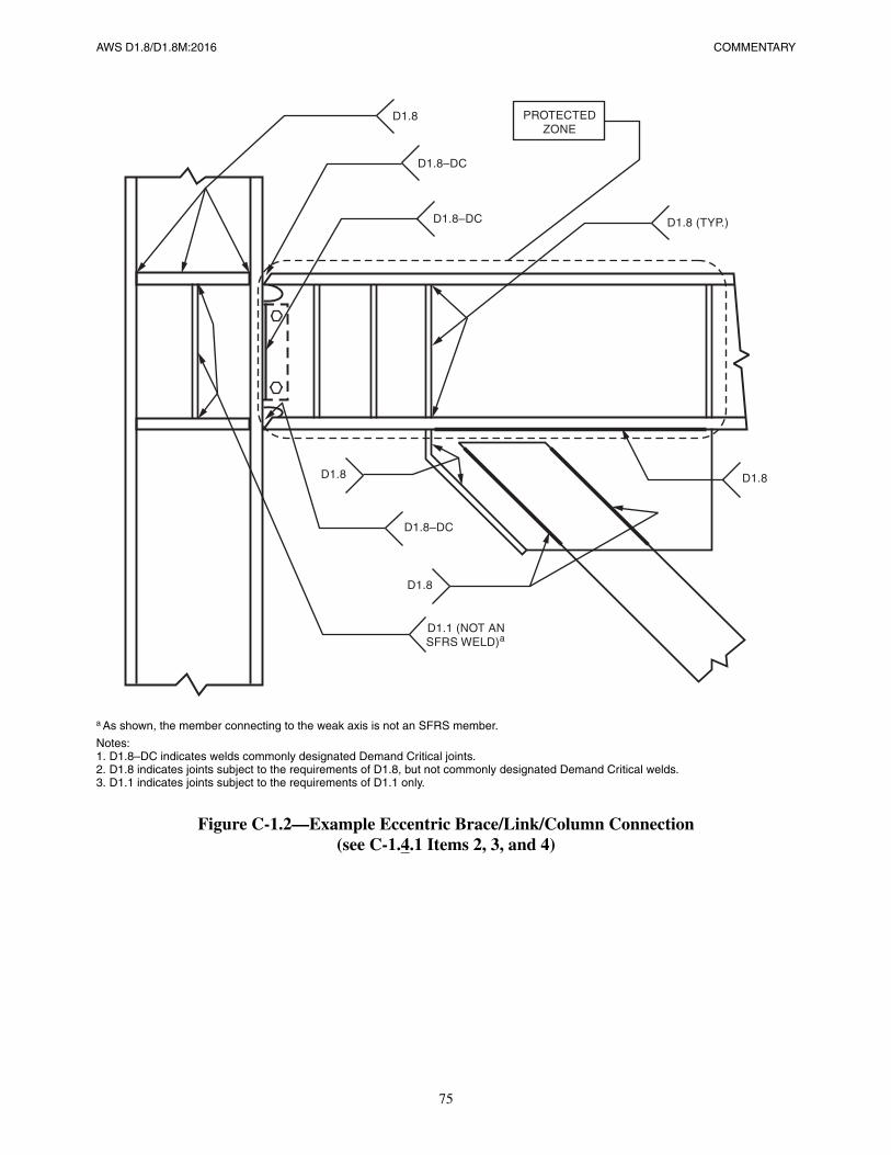
AWS D1.8/D1.8M:2016 COMMENTARY
75
a As shown, the member connecting to the weak axis is not an SFRS member.
Notes:1. D1.8–DC indicates welds commonly designated Demand Critical joints.2. D1.8 indicates joints subject to the requirements of D1.8, but not commonly designated Demand Critical welds.3. D1.1 indicates joints subject to the requirements of D1.1 only.
Figure C-1.2—Example Eccentric Brace/Link/Column Connection(see C-1.4.1 Items 2, 3, and 4)
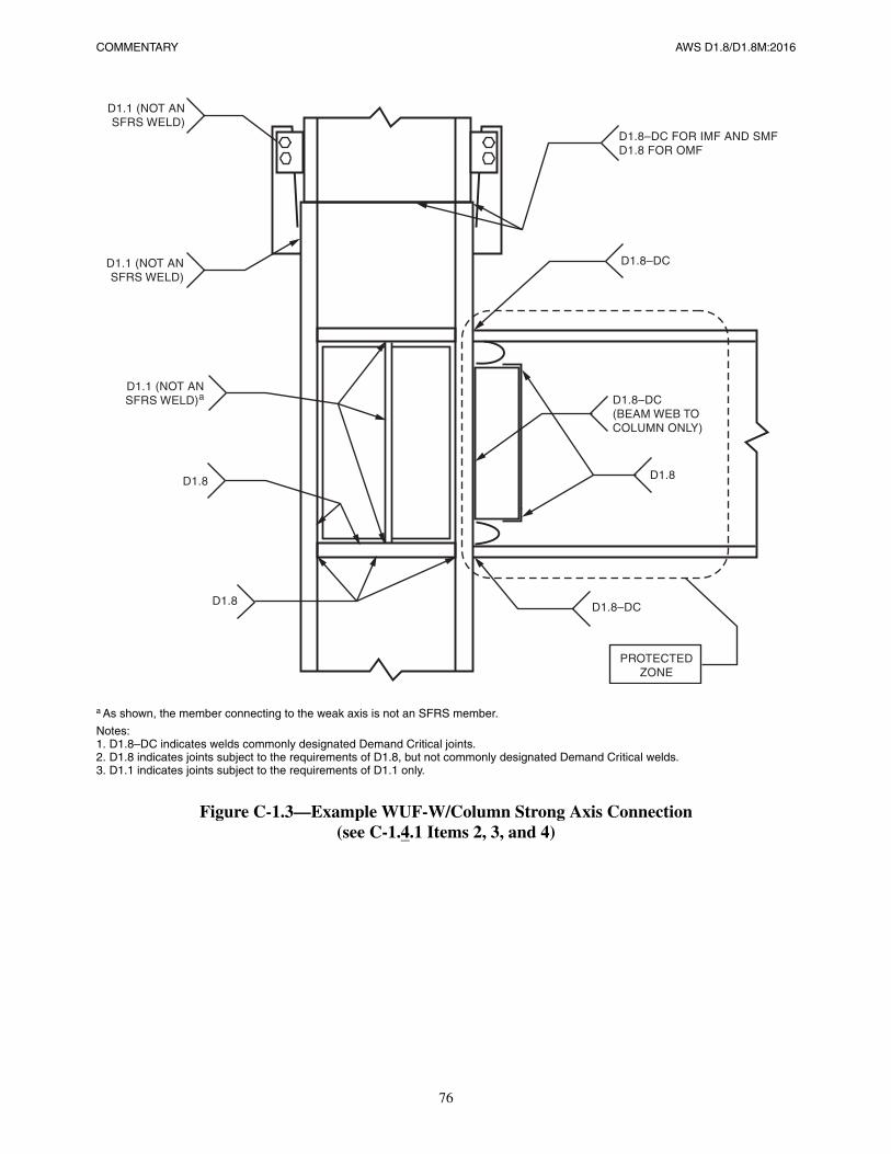
COMMENTARY AWS D1.8/D1.8M:2016
76
a As shown, the member connecting to the weak axis is not an SFRS member.
Notes:1. D1.8–DC indicates welds commonly designated Demand Critical joints.2. D1.8 indicates joints subject to the requirements of D1.8, but not commonly designated Demand Critical welds.3. D1.1 indicates joints subject to the requirements of D1.1 only.
Figure C-1.3—Example WUF-W/Column Strong Axis Connection(see C-1.4.1 Items 2, 3, and 4)
AWS D1.8/D1.8M:2016
77
C-3. Terms and Definitions
C-Demand Critical WeldsThe term “Demand Critical welds” is used to identify welds subject to extra requirements of this code. Demand Criticalwelds are further defined in AISC Seismic Provisions. The requirements are intended to reduce the likelihood of frac-ture. The requirements applicable to Demand Critical welds are identified in the text of this code. The Engineer isrequired by 1.4.1(4) to identify Demand Critical welds in the Contract Documents.
AISC Seismic Provision Commentary describes “Demand Critical Welds” as follows:
“Demand Critical Weld is a weld subjected to yield level or higher stress demand and located in a joint whose failurewould result in significant degradation in the strength or stiffness of the SFRS.” Demand Critical Joints typicallyinclude:
(1) Those identified to be Demand Critical as a result of connection prequalification analysis in accordance with AISCSeismic Provisions Chapter K,
(2) Those identified to be Demand Critical in connection qualification testing in accordance with AISC Seismic Provi-sions Chapter K,
(3) Those identified to be Demand Critical in AISC 358.
Figures C-1.1 and C-1.2 illustrate typical Demand Critical welds in moment connections and Eccentrically BracedFrames (EBFs).
C-k-AreaIn rotary straightened sections, a localized region known as the k-area may exhibit significantly altered mechanical prop-erties due to cold working during mill processing. Property changes are known to include an increase in hardness, yieldstrength, ultimate tensile strength, yield tensile ratio, and a decrease in notch toughness (see Figures C-4.1 and C-4.2).
C-lowest anticipated service temperature (LAST)LAST can conservatively be taken as the lowest outdoor temperature within the indicated recurrence interval. Condi-tions of insulation and exposure may permit a calculated increase in LAST relative to outdoor temperatures.
C-protected zoneSeismic Force Resisting Systems designed in accordance with the AISC Seismic Provisions are intended to dissipateearthquake energy through inelastic deformation in specific members and/or their connections. The locations within thestructures in which such behavior is anticipated to occur are commonly termed plastic hinges. The Protected Zone isintended to encompass those portions of the structure in which plastic hinges are anticipated to form. Special care in the
COMMENTARY AWS D1.8/D1.8M:2016
78
selection of materials, members, details, fabrication procedures, and quality control are required in these ProtectedZones to avoid failure during earthquake response (see Figures C-1.1 and C-1.2 for typical examples, see C-6.15 for fur-ther commentary).
C-quality assurance plan (QAP)The requirements for a QAP are specified by Chapter J of the AISC Seismic Provisions. The activities stipulated in thisprovision can have a significant impact in the organization of the work and cost of the project. The Quality AssurancePlan should alert the Contractor when, in the time line of construction, Quality Assurance activities are intended tooccur.
C-seismic force resisting system (SFRS)The AISC Seismic Provisions provides definitions and examples of members of the seismic force resisting system.
AWS D1.8/D1.8M:2016
79
C-4. Welded Connection Details
C-4.1 Corner Clips of Continuity Plates and Stiffeners
Some straightening processes used by mills to ensure that structural shapes are within the rolling tolerances of ASTMA6 result in extensive cold working of the webs of rolled shapes in and near the k-area. This region is defined in Clause3. This cold working can result in the altering of properties within the affected area. Property changes are known toinclude an increase in hardness, yield strength, ultimate tensile strength, yield tensile ratio, and a decrease in CVNtoughness. In some instances CVN toughness has been recorded to be less than 2 ft·lbf at 70°F [3 J at 20°C]. Fractureshave been found to extend from cuts, punches, and welds in and on these shapes in the areas of reduced notch toughness.This provision is intended to minimize the potential for such cracking during fabrication.
When the code-mandated minimum clip dimensions are imposed, the available material on which a weld may be placedmust be considered in the design and detailing of the welds to the clipped member. When fillet welds are used, the lengthof the fillet weld may be held back one to two weld sizes. For groove welds, weld tabs should not be used in the k-area(see 6.16.4). Corner clips are special cases for which minimum radii have been established by this provision and the gen-eral AWS D1.1/D1.1M requirement for reentrant corners does not apply (see Figures C-4.1 and C-4.2).
AISC and SAC investigations have shown that the locally altered properties do not negatively influence the in-servicebehavior of uncracked wide flange shapes. However, the potential for post-fabrication k-area cracking has been demon-strated in highly restrained joints at stress raisers at the termination of welds such as those associated with column conti-nuity plates, web doublers, and thermally cut coped beams. However, rare instances of k-area cracking have occurredfrom bolt holes and square cut beam ends, both with relatively smooth finishes.
To minimize the potential for k-area cracking, it is recommended, where practical, that welding into the k-area shouldnot be performed. Where k-area welding cannot be practically avoided, the reduction of residual stresses by increasedpreheat, proper weld sequencing, and minimization of weld volume is strongly suggested. The condition of beam copesand weld access holes flame cut surfaces can be improved by grinding to a smooth surface.
C-4.2 Tapered transitions are only required when specified in accordance with 1.4.1(11).
C-4.3 Joint Details for Doublers
If the doubler encroaches on the hot rolled section fillet, a space or gap is formed between the web and the doubler. Thegap between the web doubler and the web is limited as follows:
(1) For web doublers that are joined to the web with plug/slot welds, the gap is limited by the applicable code provi-sion for those welded details.
(2) For web doublers that are joined on the ends of the doubler with fillet welds, the gap is limited by the applicablecode provisions for fit up of joints to be fillet welded.
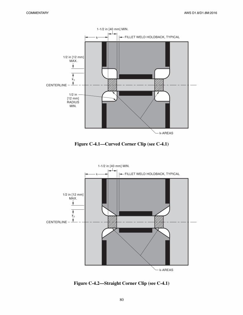
COMMENTARY AWS D1.8/D1.8M:2016
80
Figure C-4.1—Curved Corner Clip (see C-4.1)
Figure C-4.2—Straight Corner Clip (see C-4.1)
AWS D1.8/D1.8M:2016
81
C-5. Welder Qualification
C-5.1 Supplemental Welder Qualification TestingC-5.1.1 Required Tests. Some connections that fractured during the Northridge earthquake revealed problems associ-ated with the welding of bottom beam flange to column flange connections. Incomplete fusion and slag inclusions werefound concentrated in the center of the length of the weld, under the beam web. It is at this location that the welder mustwork through the weld access hole. The Supplemental Welder Qualification test described in Annex D was developed tomeasure the ability of a welder to make quality welds under these restricted conditions. The test was adapted from a sim-ilar test described in FEMA 353. The Supplemental Welder Qualification test does not replace the need for welders to bequalified in accordance with AWS D1.1/D1.1M requirements. This Supplemental Welder Qualification testing is onlyrequired for welders who will make welds meeting all three of the conditions prescribed in this provision. Welder quali-fication tests in AWS D1.1.D1.1M demonstrate ability to weld in various positions. This supplement does not requiresupplemental welder qualification tests in the various positions used in production. This qualification is not required forfillet welds or back welds of groove welds through the weld access holes.
C-5.1.2 Testing Parameters. The Supplemental Welder Qualification for Restricted Access Welding testing is requiredby this code to be performed using the same process (e.g., FCAW, GMAW, SAW, SMAW, etc.) that will be used in pro-duction. The testing is also to be performed with highest deposition rate that will be used with that process for the beamto column welds made in production. The WPS used for the qualification test is not required to be the same WPS as willbe used in production. The electrode type, diameter, amperage, voltage, electrode manufacturer, and other variables usedin production may be different than those used for the Supplemental Welder Qualification testing, providing the weldingprocess is not changed, and the deposition rate used for the qualification test is not exceeded in production.
C-5.1.3 Backing. The type of backing is an essential variable for the Supplemental Welder Qualification for RestrictedAccess Welding test. Welders must be qualified to weld on each type of backing that will be used on a project. Separatewelder qualification is required by this supplement for different types of backing (i.e., copper or ceramic), and separatequalification is required to weld open root joints, if those types of backing or joints are used in production. Separately,WPS qualification is required by AWS D1.1/D1.1M for nonsteel backing. A common test specimen can be used to qual-ify welders and the WPS, providing all the required tests for both welder qualification, and WPS qualification, can betaken from the test specimen.
C-5.2 Welder Qualification PeriodThe 36-month period was arbitrarily selected as a reasonable period for applicability. For welders that are welding on aproject and the arbitrary 36 months expires while the individual is actively making welds that meet the project weldquality standards, there is no need to requalify the welder on the Supplemental Welder Qualification for RestrictedAccess test as long as the welder continues to work on the same project.

This page is intentionally blank.
AWS D1.8/D1.8M:2016
82
AWS D1.8/D1.8M:2016
83
C-6. Fabrication
C-6.1 Filler Metal and Weld MetalC-6.1.1 AWS A5 Specification Properties. The yield, tensile, and elongation properties contained in Table 6.1 are min-imum values—higher values are acceptable. No maximum values have been placed upon the yield or tensile strength ofthe weld metal. Welds are not designed to participate in inelastic strain mechanisms, so higher weld metal strengths donot affect deformation capabilities in that inelastic strains are not expected to be concentrated in welds.
The CVN toughness properties listed in Table 6.1 are minimum values. Higher absorbed energy values (ft·lbf) [J] areacceptable. Testing at lower temperatures (such as –40°F [–40°C]) is more demanding, and therefore, filler metals testedat lower temperatures are acceptable, providing the minimum absorbed energy level is achieved.
C-Table 6.1 Filler Metal Classification Properties. A variety of weld metal CVN requirements have been developedin the post-Northridge era. FEMA 267 (August 1995) stated that “for critical joints” (later defined as beam to columnCJP groove welds), a “minimum CVN value of 20 ft·lbf at a temperature of 0°F should be required, unless more strin-gent requirements are indicated by the service conditions and/or the Contract Documents.” This testing was to be done inaccordance with the AWS filler metal specifications (see FEMA 267, page 8-11).
AISC Seismic Provisions (April 1997) incorporated the general concepts contained in FEMA 267, and incorporatedthem into provision 7.3b. This provision required that CJP groove welds in the SFRS be made with a filler metal with aminimum CVN toughness of 20 ft·lbf, but the testing temperature was changed from 0°F to –20°F.
In FEMA 353 (July 2000), the FEMA 267 recommendations for CVN notch toughness of 20 ft·lbf at 0°F was retained,but the coverage was expanded to include “all welds on members comprising the Seismic Force Resisting System.”Additionally, all welds were recommended to meet 40 ft·lbf at 70°F, when tested in accordance with procedures as pre-scribed in Appendix A of FEMA 353. These procedures are similar to those required by Annex A of this code (seeFEMA 353, Part I: 2-3).
AISC Seismic Provisions (May 2002) incorporated the general concepts contained in FEMA 353, identifying two typesof welds: type 7.3a welds (all welds that are part of the SFRS) and type 7.3b welds (certain CJP groove welds in specificsituations). For the 7.3a welds, the filler metals were required to be classified with CVN notch toughness of 20 ft·lbf at–20°F. For the 7.3b welds, an additional CVN requirement of 40 ft·lbf at 70°F was required, as determined by AppendixX of the AISC Seismic Provisions. Appendix X was similar to FEMA 353 Appendix A, and Annex A of this code.
The AISC Seismic Provisions (March 2005) revised the requirement for welds that are part of the SFRS (7.3a), changingthe filler metal classification CVN toughness to 20 ft·lbf at 0°F or a lower temperature, rather than 20 ft·lbf at –20°F. Therequirements for what was termed “Demand Critical” welds (7.3b) remained unchanged, e.g., filler metals must be clas-sified with a CVN toughness of 20 ft·lbf at –20°F or lower temperature, and an additional requirement of 40 ft·lbf at70°F or lower temperature as determined by Appendix X of the Seismic Provisions.
This code has incorporated the concepts of two weld types (part of the SFRS, and Demand Critical welds), and two CVNrequirements: 20 ft·lbf in the AWS classification test, and 40 ft·lbf [54 J] at 70°F [20ºC] in the Annex A test. Toughnessat the service temperature is the relevant property, therefore, this code requires the classification test temperature be 0°Ffor all welds as was recommended in FEMA 267 and FEMA 353, not the –20°F temperature as required for all weldspart of the SFRS by AISC Seismic Provisions (both 1997 and 2002) or for Demand Critical welds by AISC Seismic Pro-visions (2005). As specification requirements continue to develop, it is important for Contract Documents to address any
COMMENTARY AWS D1.8/D1.8M:2016
84
inconsistencies that may exist between specifications (see C-1.4.1). The 2016 edition of this supplement added provi-sions for the use of E90 [E62] filler metals to weld 70 ksi [490 MPa] yield steel that was accepted for use in seismicallyloaded structures in the AISC Seismic Provisions. In response to the higher stresses potentially in these welds the classi-fication toughness requirements were set to 25 ft·lbf at –20°F and the service temperature tests were set at the lowestanticipated temperature without a 20° shift.
C-6.1.3 Diffusible Hydrogen Level. All welding electrodes for processes approved by this code (see 6.5.1) are expectedto meet the diffusible hydrogen requirements for H16. This provision also applies to each SAW electrode/flux combina-tion to be used on the project. Carbon steel FCAW electrodes need to meet the further testing restrictions described inAWS A5.20/A5.20M Clause 16 or AWS A5.36/A5.36M:2012 Clause 15. The supplement permits low alloy FCAWelectrodes tested to the diffusible hydrogen requirements in AWS A5.29/A5.29M Clause 15, which meet the require-ments of H16 or less they are acceptable for use in Demand Critical welds. Costly testing and schedule impact can beeasily avoided by requesting this information from the electrode and flux manufacturers.
The applicable filler metal specifications for FCAW, GMAW, SAW, and most SMAW electrodes do not require testingto determine diffusible hydrogen content. However, such testing is performed if the optional diffusible hydrogen desig-nators are used. This code requires that the filler metals used not exceed a diffusible hydrogen content of 16 ml/100 g.Documentation of conformance to the testing prescribed is required by this supplement (see 1.4.2.4). SMAW electrodesmay be accepted based upon moisture content.
C-6.1.4 Intermix of FCAW-S Filler Metal. Research has found the intermixing of the self-shielded flux cored arcwelding process (FCAW-S) and electrodes with other welding processes and electrodes may exhibit some degradationof notch toughness values in the intermixed deposit. This supplement requires testing of intermixed weld metal when theFCAW-S process is used in combination with any other welding process. This testing is done to ensure the minimumnotch toughness requirements are met. No other process combinations are required to be tested by this code. This provi-sion does not require intermixed combinations of various FCAW-S electrodes to be tested.
A variety of intermix tests were performed before the issuance of this code. These would include both tests performed inaccordance with FEMA 353, as well as research performed in conjunction with various SAC investigations. Eventhough some of the details of these other tests might be slightly different than those of Annex B, alternative test resultsmay be accepted by the Engineer. The Engineer should evaluate the relative similarity of the alternative tests to thoserequired by this code, and FEMA. The Contractor should provide sufficient background documentation to the Engineerfor this evaluation.
C-6.2.1 WPS Heat Input Envelope Testing Properties. The purpose of WPS Heat Input Envelope Testing prescribedin Annex A is to demonstrate that the minimum required strength, ductility, and CVN toughness will be achieved and toavoid needless repetitions of welding procedure qualification tests. Weld cooling rates as determined by heat input, pre-heat, interpass temperature, and material thickness are known to affect mechanical properties of weld metal and heat-affected zones. While all welds and base metals are affected to some extent, the influence of cooling rates becomes morepronounced in high yield strength steel, particularly those steels that are quenched and tempered, and “matching” weldmetals which require martensitic or bainitic microstructures for the required properties. The structural steels used inbuilding construction and the E70 [E48] and E80 [E55] filler metals are less sensitive to weld cooling rates, particularlyin terms of yield and tensile strength. Notch toughness properties, as measured by CVN specimens, are more signifi-cantly affected by cooling rates.
This supplement does not require that WPSs be qualified by test. However, to ensure that the required mechanical prop-erties are achieved in production, this supplement requires that the filler metal to be used in making Demand Criticalwelds be evaluated at a high and low heat input level. The Contractor may then use any combination of WPS values thatresult in a heat input level between the high and low value. Compliance with AWS D1.1/D1.1M prequalified WPS pro-visions still applies. The welding progression, whether a weave bead or stringer bead, is not limited by this code, pro-vided that the heat input range is maintained. The AWS D1.1/D1.1M limitations on layer thickness and width, coupledwith the heat input limitations of this code, are considered to be adequate controls on weld metal mechanical properties.
The 40 ft·lbf [54 J] CVN energy absorption level was established by research performed in conjunction with the SACproject. The 70°F [20°C] test temperature was established by the same research. This value is typically appropriate forenclosed buildings. When specified by the Engineer in accordance with 1.4.1(10), alternate test temperatures are required.
AWS D1.8/D1.8M:2016 COMMENTARY
85
CVN testing of weld metal in accordance with Annex A, but performed at a temperature lower than the required testtemperature, automatically meets the CVN requirements of Table 6.2 since this is a more demanding testing condition.The absorbed energy level of 40 ft·lbf [54 J] is a minimum requirement; higher values are acceptable.
Regardless of the welding process or the filler metals involved, the expectation is that Demand Critical welds have theproperties listed in the Table 6.2. SMAW performed with either E7018 [E4918] or E8018 [E5518] electrodes, orGMAW performed with solid electrodes, routinely deposit welds with these mechanical properties and therefore, it isnot necessary to perform the tests required by Annex A for these processes/filler metals.
Subclause 6.8.1 of this code requires that WPSs be operated within the range of heat inputs, a heat input envelope, whichhave been tested. Carbon steel FCAW electrodes classified with the supplemental designator “-D” have been heat inputenvelope tested by the manufacturer as described in Clause 17 of AWS A5.20/A5.20M:2005. The prescribed testingused to classify a filler metal with the supplemental designator “-D” is similar, but not identical to, the testing defined inAnnex A, and are exempt from Annex A testing for use in Demand Critical welds as defined by this code. As of the timeof publication of this document, AWS A5.29/A5.29M does not include heat envelope testing. Low Alloy FCAW elec-trodes classified to AWS A5.29/A5.29M that have been optionally tested by the filler metal manufacturer as described inAWS A5.20/A5.20M:2005 Clause 17 for designator “-D” are deemed exempt from Annex A testing. The heat inputenvelope indicated by the designator “-D” is 30 kJ/in [1.2 kJ/mm] to 80 kJ/in [3.1 kJ/mm] for electrodes <3/32 in[2.4 mm], and 40 kJ/in 1.6 kJ/mm] to 80 kJ/in [3.1 kJ/mm] for electrodes 3/32 in [2.4 mm] and over. Annex A has a30 kJ/in–80 kJ/in [1.2 kJ/mm–3.1 kJ/mm] heat input range (unless tested at alternate limits), regardless of electrodediameter. This supplement requires the more restrictive range to be used in production.
AWS A5 Committee on Filler Metals released a new specification, AWS A5.36/A36M:2012, Specification for Carbonand Low-Alloy Steel Flux Cored Electrodes for Flux Cored Arc Welding and Metal Cored Electrodes for Gas MetalArc Welding, which has requirements for an optional “-D” designator but not identical to AWS A5.20/A5.20M “-D”designator. The discrepancy is in the heat input requirements, in particular the high heat input. The AWS A5.20/A5.20Mhigh heat input is 80 +5/–2 kJ/in [3.1 +0.2/–0.1 kJ/mm] compared to AWS A5.36/A5.36M high heat input of 65 kJ/in–85 kJ/in [2.6 kJ/mm–3.3 kJ/ mm). There are also some minor changes in the low heat inputs as well. Due to these dif-ferences, the two “-D” designators, products with the AWS A5.36/A5.36M “-D” designator are not interchangeablewith “-D” designator of AWS A5.20/A5.20M. Fabricators using electrodes classified under AWS A5.36/A5.36M withoptional “-D” designator should review the operating heat input range in which the electrode was classified at to ensurethe WPS has the same lower and upper heat input range as the electrode. (See AWS A5.20/A5.20M Table 9 reproducedas Table U.7 in D1.1/D1.1M:2015, AWS A5.36/A5.36M, Table 10 reproduced as Table U.8 in D1.1/D1.1M:2015 andAWS A5.36/5.36M Annex A.)
C-6.2.2 Lowest Anticipated Service Temperature Applications. The use of a testing temperature not more than 20°F[10°C] higher than the LAST is to adjust for the effect of loading rate in 70 ksi [490 MPa] and 80 ksi [550 MPa] fillermetals. For 90 ksi [620 MPa] filler metals, the effect of loading rate is less so no temperature shift is permitted. TheEngineer needs to specify the LAST when this is less than +50°F [+10°C]. This provision applies only to Demand Criti-cal welds [see 1.4.1(10), Clause 3]. For example, if LAST is +5°F [–15°C], then the testing temperature should be nohigher than +25°F [–5°C] for welds using 70 ksi [490 MPa] or 80 ksi [550 MPa] filler metals or +5°F [–15°C] for weldsusing 90 ksi [620 MPa] filler metals.
C-6.3.1.2 Alternative to Production Lot Testing. Mechanical properties of weld metal vary in part due to variationin raw materials and production practices in the manufacture of filler metals and fluxes. Testing of each production lotprovides a relatively high level of assurance that production variances are in control but such lot testing of consumablesis expensive and historically has caused interruption in the availability of useable product. Filler metals are commonlyproduced using quality systems to provide assurances of product consistency. Certification to recognized quality man-agement standards provides a level of assurance that production processes are in control. Once the consistent capabilityto achieve the required mechanical properties is established, certification to one of the listed quality system criteria isconsidered to provide an adequate level of assurance that consumables furnished are manufactured consistently withclassification tested materials. This requirement is similar to the controls used in the welding code for bridges in the fab-rication of fracture critical members.
The requirement for three different lots of filler metals to be tested is a measure of production consistency.
COMMENTARY AWS D1.8/D1.8M:2016
86
Certificates of Conformance or other test data from three different lots of material, as tested by the filler metal manufac-turer, will satisfy this requirement, and should be retained by the filler metal manufacturer, and made available to theContractor upon request. The Contractor should be certain that such documentation is available.
C-6.3.1.3 Exemptions. SMAW performed with either E7018 [E4918] or E8018 [E5518] electrodes, or GMAW per-formed with solid electrodes, routinely deposit welds with these mechanical properties and therefore, it is not required toperform the tests required by 6.3.1 for these process/filler metals.
C-6.4 FCAW Electrode Packaging, Storage, and ExposureC-6.4.1 Packaging Condition. FCAW electrodes may absorb moisture when exposed to humid conditions. Electrodepackaging ranges from simple cardboard boxes, to hermetically sealed foil bags. Not all packaging is capable of protect-ing filler metals from moisture absorption. Opened or damaged packaging is incapable of protecting filler metals frommoisture absorption.
C-6.4.3 Exposure Time Limits for FCAW Electrodes. FCAW electrodes, like SMAW electrodes, can absorb moisturefrom the atmosphere. Such increases in moisture can increase the possibility of hydrogen assisted cracking. Because ofthe critical nature of welds in the SFRS, and the consequence of undetected cracks during major seismic events, thiscode imposes additional exposure criteria upon FCAW electrodes. AWS D1.1/D1.1M provisions for SMAW electrodesare considered adequate for this code’s applications.
The rate of moisture absorption is dependent on many factors, including the design of the filler metal. These provisionsare specific to the filler metal manufacturer’s brand and type of electrode.
Test data suggests that 72 hours is a conservative upper limit for electrode exposure, in the absence of specific exposuredata.
When welding is suspended, it is possible to store the electrode under conditions where no additional accumulation ofmoisture is expected to occur. When this is done, the exposure time is stopped. The time resumes when the filler metal isremoved from the protective storage conditions and put back onto the welding machine.
C-6.4.4 Overexposed FCAW Electrode. When electrodes used for Demand Critical welds have exceeded the exposuretime limit as determined by tests performed in accordance with Annex E, or the 72 hours of exposure when no test datais available, whichever is applicable, the electrodes may be dried at the option of the Contractor. Alternately, the Con-tractor may elect to use the electrode for other than Demand Critical welds. If the Contractor elects to dry the electrode,it is done in accordance with the electrode manufacturer’s recommendations. Manufacturers have different guidelineswith respect to drying of electrodes, including some electrodes for which no such drying is recommended. At a mini-mum, the guidelines must identify drying temperatures and times. It is possible that a specific spool or coil of electrodecould be exposed, dried, exposed and subject to additional drying cycles. If this is done, the manufacturer’s recommen-dations must state that this is permitted.
C-6.5 Welding ProcessesC-6.5.1 Approved Processes for Demand Critical Welds. Prequalification and qualification of connection details isgoverned by AISC Seismic Provisions, and should not be confused with prequalification and qualification of WPSs,which is governed by AWS D1.1/D1.1M.
SMAW and FCAW have been successfully used for connection qualification testing in the U.S., and in Japan, GMAWhas been used. SAW, although not specifically known to have been tested in seismic moment connections, has beenincluded in these approved processes because appropriate mechanical properties can be achieved with the process, andheat input levels may be similar to those employed in other tests. These processes are also those with which prequalifiedWPSs may be used. There is not a sufficient database of test results that documents the acceptability of processes such asESW and EGW, and thus, these processes are not permitted to be used without specific supporting connection qualifica-tion tests, or as approved by the Engineer.
Specific WPS parameters are not required to be qualified by connection qualification tests. Unless approved by the Engi-neer, processes other than those listed in 6.5.1 (but not the specific WPS parameters) are required by this code to be
AWS D1.8/D1.8M:2016 COMMENTARY
87
tested in the connection qualification tests. The essential variables of AWS D1.1/D1.1M still apply, and while the WPSmay require retesting, the connection test need not be replicated for changes in WPS essential variables.
The ability of moment-resisting connections to successfully dissipate earthquake energy is dependent on a large numberof factors including connection geometry, member size, strength, notch toughness, and chemical composition of the basemetals, welds, and heat-affected zones (HAZs), as well as other factors. A large number of laboratory tests and analyti-cal investigations were conducted to confirm that connections having certain geometry, material and construction char-acteristics could perform acceptably. Joints welded with processes other than the prequalified processes were notincluded in the scope of investigations that serve as the basis for these documents. However, the AISC Seismic Provi-sions recommend procedures for verifying that connections employing alternative geometric, design, or constructionfeatures are capable of acceptable performance. It is recommended that the Engineer consider using the same connectionqualification methods contained in the AISC Seismic Provisions as the basis for approval to qualify the use of weldedjoints employing processes other than the four prequalified processes listed in 6.5.1. Alternatively, tests that consider theeffect of the welding process on HAZ properties, the propensity of the process to produce various weld discontinuities,and the inspectability of joints made with these processes, could be used as the basis for approval.
C-6.6 Welding Procedure Specifications (WPSs)
WPSs for Demand Critical welds are required by this code to be based on the heat inputs used for the testing describedin Annex A. The Contractor is required by this supplement to record the filler metal manufacturer and trade name of theproduct used in the WPS because the heat input envelope could be different for each manufacturer and filler metal man-ufacturer and type. The parameters chosen for the WPS are required by this code to be within the heat input range usedfor the WPS Heat Input Envelope Test. If the Contractor chooses to note parameter “ranges” on the WPS, it will be nec-essary to verify that the full range on the WPS is within the heat inputs used in the WPS Heat Envelope Test. It is notnecessary for the Contractor to use the exact parameters listed in the WPS Heat Input Envelope Test (volts, amps, travelspeed), but the parameters chosen are required by this code to result in a calculated heat input between the high and lowheat inputs tested. The AWS D1.1/D1.1M heat input calculation is used to calculate heat input and establish the WPSparameters, e.g., Heat Input (kJ/in) = (60 × volts × amps)/(1000 × travel speed) (in inches per minute) [Heat Input(kJ/mm) = 60 × volts × amps/1000 × travel speed (in mm per minute)].
WPSs may show a range of acceptable values for certain welding variables. Some of these variables will affect deposi-tion rates. Such variables include amperage, electrode diameter, electrical extension (electrical stick out), and polarity.For welds where the welder qualification includes a qualified maximum deposition rate, the WPS used in production forthose joints requiring such welder qualification needs to show limits that will ensure that the welder will not exceed themaximum deposition rate for which he/she is qualified.
C-6.6.3.1 Gas-Shielded Processes. Weld metal ductility and CVN toughness has been shown to degrade withincreasing air velocity and loss of shielding when gas-shielded processes are used. Before porosity is seen, notch tough-ness has been shown to decrease. With wind speeds of 8 mph to 10 mph [3.6 m/s to 4.5 m/s], welds may have significantinternal porosity without visual indication of surface-breaking porosity (References: FEMA 355B, State of the ArtReport on Welding and Inspection, Chapter 6, Federal Emergency Management Agency, 2000, and SAC/BD-00/12,Evaluation of the Effect of Welding Procedure on the Mechanical Properties of FCAW-S and SMAW Weld Metal Usedin the Construction of Seismic Moment Frames, M. Q. Johnson, 2000.)
Precise monitoring of wind speed is not intended by this provision. Three mph winds [5 kph] will cause modest driftingof smoke or welding fume. Higher speed can be felt on the face and as well as cause modest rippling of water surfaces.Wind velocity is to be estimated in the immediate weld area rather than in the general atmospheric condition.
AWS D1.1/D1.1M has a maximum wind speed limit of 5 mph [8 kph]. This has been deemed acceptable since AWSD1.1/D1.1M does not have mandatory CVN toughness requirements. The more conservative value of this code has beenimposed due to the concern for CVN toughness of welds that are part of the SFRS.
C-6.6.3.2 Non Gas-Shielded Processes. The self-shielded processes listed are considerably more tolerant of airvelocity. In SMAW, the electrode flux provides a gas to shield the arc and a slag blanket to protect the molten metaldroplets and the weld pool. In SAW, the metal droplets and weld pool are covered by the granular flux.
COMMENTARY AWS D1.8/D1.8M:2016
88
In FCAW-S, shielding is provided by vaporized flux ingredients that displace the air, a slag composition that covers themolten metal droplets and the weld pool, and a weld metal composition that protects the weld metal from the potentiallyharmful effects of nitrogen. Compared to FCAW-G, which showed significant decrease in CVN toughness with increas-ing wind speed, no effect on CVN toughness was noted for FCAW-S for wind speeds of 18 mph [8 m/s]. (Reference:FEMA 355B, State of the Art Report on Welding and Inspection, Chapter 6, Federal Emergency Management Agency,2000) (SAC/BD-00/12, Evaluation of the Effect of Welding Procedure on the Mechanical Properties of FCAW-S andSMAW Weld Metal Used in the Construction of Seismic Moment Frames, M. Q. Johnson, 2000.)
C-6.7 Maximum Interpass TemperatureC-6.7.1 Standard Maximum Interpass Temperature. The concern for maximum interpass temperature is related tothe potential for slow weld cooling rates to adversely affect the mechanical properties. Refer to C-6.2.1 for discussionof cooling rates. Maximum interpass temperature needs to be measured relatively close to the weld, not more than 3 in[75 mm] away but not closer than 1 in [25 mm].
In contrast, minimum preheat temperature and minimum interpass temperature are measured at least 3 in [75 mm] fromthe weld to better ensure that the entire volume adjacent to the weld will be at or above the preheat and interpass temper-ature. The minimum preheat and interpass temperatures have evolved based on avoidance of cracking (see Figure C-6.1).
The 550°F [300°C] maximum temperature is a conservative value that is considered appropriate for steels and weld met-als permitted for construction of SFRS members. Higher interpass temperatures may be acceptable, and are permitted ifthe higher value is established by test.
C-6.7.2 Alternative Maximum Interpass Temperature. Limitations on maximum interpass temperature are imposedbecause laboratory data indicates that excessive slow cooling rates may result in degradation of weld and HAZ strengthand notch toughness. Temperature indicating crayons, if used, should not be marked within the weld joint area. Maxi-mum interpass temperature is measured at a distance not greater than 3 in [75 mm] beyond the joint nor closer than 1 in[25 mm] (see Figure C-6.1).
To qualify the maximum interpass temperature, it will probably be necessary for the test plate to be heated to the maxi-mum temperature after the first weld pass is applied before welding is resumed. It is permitted to heat the test platebetween passes to maintain the interpass temperature that is being qualified. The test plate may cool to a lower tempera-ture between weld passes and the test remain valid, providing the test plate is heated to at least the interpass temperaturebeing qualified.
C-6.9 Bottom Flange Welding SequenceExamination of some fractured connections following the 1994 Northridge California earthquake revealed incompletefusion and entrapped slag under the beam web, against the column face. This suggests that weld passes were eitherstarted or stopped at this one location, resulting in significant weld defects. Staggering the weld starts and stops on oppo-site sides of the beam web should reduce this problem, provided proper weld cleaning is performed after each weld passis deposited. The direction of weld travel is not controlled by this provision.
C-6.10 Welder IdentificationA welder identification system is required by this supplement for a number of reasons:
(1) It can serve as a means to identify sources of consistently poor quality welded joints.
(2) It may serve to enable a reduction in the percentage of NDT required for highly qualified welders who displayconsistent quality and conformity.
Welder identification stamps of the low-stress type are required by this code to minimize the potential for accidentalnotching near the joint, which could result in stress concentrations that would affect the anticipated ductile performanceof the structure.
AWS D1.8/D1.8M:2016 COMMENTARY
89
C-6.11 Weld Access HolesC-6.11.1.1 Standard AWS D1.1/D1.1M Geometry. The AWS D1.1/D1.1M weld access hole geometry is accept-
able for all welds on the SFRS, including Demand Critical welds, unless alternate geometries are specified by the Engi-neer, as required by 1.4.1(9).
Some of the AISC prequalified moment-resisting connections require that weld access holes conform to specific criteria.Nothing in this subclause should be interpreted to override the AISC requirement to conform to the limitations andrequirements of individual connection prequalifications. The Engineer is responsible for ensuring that all fabrication anddetailing limitations applicable to a specific prequalified connection are specified in the Contract Documents.
C-6.11.1.2 Alternate Geometry. The access hole geometry shown in Figure 6.2 was subject to finite element analy-sis, physical testing, and demonstrated in the SAC project to provide improved performance for some connections. Itmay not be required for all connection types. At the Contractor’s discretion, the alternate geometry may be used in lieuof the standard AWS D1.1/D1.1M geometry. (References: SAC/BD 00/24 Development and Improvement of ImprovedDetails for Ductile Welded Unreinforced Flange Connections, Ricles, Mao, Lu, and Fisher.)
C-6.11.1.3 Special Geometry. For connections where the performance is dependent upon the use of a special weldaccess hole geometry, including situations where no access hole is to be used, the details of such access holes are to befully defined, including applicable tolerances.
C-6.11.2 Quality Requirements for Weld Access Holes. Grinding will likely be necessary if the hole is cut with amanually guided torch. If the hole is cut by a guided torch some cleanup may be needed. If the hole is drilled and sawn,additional grinding may not be needed. It is preferable to repair weld access hole imperfections by grinding. Whenwelded repairs are needed, after welding, the welded region must be ground not only to a smooth condition, but also tosound metal, to ensure no notches, cracks, or other defects exist in the area of the welded repair (see 7.7). The directionof grinding marks that meet 6.11.2.1 is not significant, and need not be controlled.
C-6.12 Tack Welding RequirementsC-6.12.1 Preheat. Tack welding is required by this supplement to be performed by qualified personnel using approvedWPSs. The preheat for tack welding is required to be in accordance with the approved WPS. The WPS for tack weldingmay be different than the WPS to complete or weld the required joint. Tack welds are generally small and will createheat-affected zones of proportionate sizes. The HAZ may be harder than the adjacent base metal, depending on weldcooling rate and base metal composition. Tack welds may also create mechanical notches. The welding process or elec-trode used for tack welding may be different than that used for the final welding, and therefore the preheat requirementfor tack welding may be different.
C-6.12.2 Placement of Tack Welds. By placing the tack welds within the joint, the potential for surface notches andhard heat-affected zones is minimized. The tack weld HAZ will be tempered by subsequent passes when placed withinthe joint. In the Protected Zone it is desirable not to have any unnecessary hard spots or mechanical notches because thiszone is expected to be capable of deforming in an inelastic manner. Thus, tack welds in the Protected Zone are requiredby this supplement to be placed such that they will subsequently be covered by a weld.
C-6.12.3 Tack Welds to Steel Backing in the Protected Zone
Tack welds for beam flange to column connections are required by this supplement be made in the weld groove. How-ever, steel backing may be welded to the column under the beam flange. Tack welds to the underside of beam flanges areprohibited by this supplement. The tack welds holding weld tabs are required by this supplement to be removed in accor-dance with 6.16.3.
It is generally preferable, but not always practical or even possible, to place tack welds inside the weld joint. By placingthe tack welds within the joint, the potential for surface notches and hard heat-affected zones is minimized. The HAZ ofthe tack weld will be tempered by subsequent passes when placed within the joint.
Compatibility of weld metal used for tack welds within the joint must be determined in accordance with Clause 6.1.4.Tack welds in joints need to be of a size and configuration so as to not interfere with subsequent weld passes (see AWS
COMMENTARY AWS D1.8/D1.8M:2016
90
D1.1/D1.1M 5.17). Tack welds outside weld joints may create alternate, unintended load paths, and improperly madetack welds may create stress concentrations that may be the point of crack initiation when highly strained.
C-6.12.4 Removal of Improperly Placed Tack Welds. If tack welds are inadvertently made in the Protected Zone, thetack welds are required by this supplement to be completely removed and the base metal ground smooth and flush.
C-6.13 Removal of Backing and Weld Root TreatmentObservations and studies performed after the 1994 Northridge earthquake found that left-in-place, steel (fusible) backingcreated notch effects at the root of the beam flange to column flange weld. Even in a weld with uniform and sound fusionin the root, the naturally resulting lack of fusion plane between one edge of the backing and the column flange created astress concentration. Additionally, left in place backing can obscure the ultrasonic inspection detection of significantflaws that may exist at the weld root. These flaws can represent a much more severe notch condition than results fromthe steel backing itself.
When backing (fusible or nonfusible) is removed, backgouging to sound metal is required by this provision to provideassurance that potential root flaws within the welded joint are detected and eliminated.
It was also discovered after the Northridge earthquake, and the subsequent investigations, that the influence of left-in-place steel backing is more severe on the bottom flange, as compared to the top flange. This observation assumes that thebacking is on the underside of the beam flange in both cases. When the backing is in this configuration for the bottomflange, the stress concentration occurs at the point of maximum stress in the groove weld. When similarly configured forthe top flange, the notch effect due to the backing is at a lower stress point. Additionally, removal from the top flangenecessitates that the removal and rewelding operations be performed through an access hole, making this a complicatedoperation. Thus, backing removal is not required in all cases (see 6.15). (Reference: SAC/BD-97/05, Finite ElementFracture Mechanics Investigation of Welded Beam-Column Connections, W. M. Chi, G. Deierlein, A. Ingraffea.)
C-6.14 Reinforcing Fillet Welds at Removed Weld Backing LocationsEvaluation of Northridge failures and subsequent test results has shown that the intersection of the column to beam bot-tom flange is an area of very high demand. A reinforcing fillet weld with a 5/16 in [8 mm] leg on the column flangehelps to minimize notch effects. The fillet weld’s horizontal leg may need to be larger to completely cover the weld rootarea. The resultant fillet weld may have unequal leg sizes, with the horizontal leg being larger.
C-6.15 Fillet Welds at Left-in-Place Steel BackingC-6.15.1 Minimum Fillet Weld Size. In situations where backing is permitted to remain, it is required to apply a filletweld in order to reduce the stress concentration associated with the naturally occurring plane that is not fused to the col-umn, created by the presence of the steel backing. When this is to be done, it is to be specified in Contract Documentsper 1.4.1(6) (see Figure C-6.2).
C-6.15.2 Prohibited Welds on Left-in-Place Steel Backing. Welds that join the backing to the beam flange attractmore stresses into the backing, increasing the effect of the stress concentration that occurs at the interface of the backingand column flange. This is true whether the weld is a continuous weld or a tack weld. If welds are placed in this regionby accident, the welds must be removed in accordance with 6.18.4 (see Figure C-6.2).
C-6.16 Weld TabsC-6.16.1 Minimum Weld Tab Length. Welds are sometimes specified for the full length of a connection. When jointsare shown to be welded full length to intersecting pieces with small clipped corners, the minimum weld tab length maynot be possible at the clipped corner. Similar conditions exist in the corners of continuity plates adjacent to the k-area ofcolumns.
AWS D1.8/D1.8M:2016 COMMENTARY
91
C-6.16.2 Tack Welds Attaching Weld Tabs. Tack welds used to attach weld tabs, placed outside the weld joint, maycreate notches or other discontinuities that may serve as crack initiation sites. When tack welds to join weld tabs areplaced within the weld joint, they become part of the final weld.
C-6.16.4 Weld Tabs for Continuity Plates. Detailing of the corners of continuity plates needs to account for the k-areadimension, and depending on the sizes of the members involved, weld tabs at this location are not desirable, and may notbe practicable (see 6.16.1 and Figure C-6.3). Under these conditions, the weld ends may be cascaded or other approachesused. Both the design and detailing need to consider these factors. Weld tabs at this location, if used, should not beremoved because the removal process has the potential of causing more harm than good.
The opposite (outboard) end of the continuity plate to column flange generally permits the use of weld tabs in accor-dance with 6.16.1.
C-6.17 End DamsEnd dams are devices arranged essentially perpendicular to a weld’s centerline, intended to block the flow of moltenweld metal and slag from the ends of weld joints. End dams, placed directly on the end of the groove weld joint, are pro-hibited by this supplement because welds placed into the resultant corner are likely to contain defects. End dams prohibitmolten weld metal and slag from dripping from the end of the weld which can injure workers below and cause fires.When placed at the end of weld tabs, any weld defects will be located outside the length of the weld joint. Placement ofend dams at the end of weld tabs is permitted by this supplement only when weld tabs are required to be removed. Theminimum length of weld tab should be maintained when end dams are added to the end of weld tabs.
C-6.18 Protected ZoneC-6.18.1 Attachments and Welds. Because of the desire to avoid stress concentrations that could lead to fracture inregions of high plastic strain, both this code and AISC Seismic Provisions include a prohibition on placement of weldedattachments in the Protected Zone. Such a fracture occurred in a moment connection test with a composite floor slab atthe location of a welded shear connector. The same researchers found that puddle welds in this region were not a con-cern, and hence, these welds are permitted. This code has defined a region where these prohibitions and other specialprocedures are to occur as the “Protected Zone.” (Reference: See SAC/BD-00/24, Development of Improved Details forDuctile Welded Unreinforced Flange Connections,” by J. M. Ricles, C. Mao, L. W. Lu, and J. Fisher.)
C-6.18.2 Erection Aids. There may be some instances where erection aids need to be placed in the Protected Zones.Additionally, attachments to meet OSHA safety requirements may be necessary. In these and other such cases, erectionaids and attachments to the Protected Zone need to be approved by the Engineer to ensure that they will not result instress concentrations that could cause a fracture in a seismic event. If erection aids are to be placed within the ProtectedZone, it may be necessary to remove the erection aid afterwards, and the surfaces of the Protected Zone may need to beprepared by grinding to remove any notch effects. Good welding practices, including proper preheat, should be usedwhen erection aids are attached.
C-6.18.4 Correction of Errors. When fillet welds are placed between the backing and the column in tee joints, thestress concentration factor associated with the naturally occurring lack of fusion plane between the backing and columnis reduced. When welds are placed between the backing and the underside of the beam, more stress is conducted throughthe backing, and the effect of the stress concentration is magnified (see Figure C-6.2).
C-6.18.5.1 Grinding. Gouges and notches can act as stress raisers, and points for crack initiation, particularly inregions such as the Protected Zone. Stress concentrations that are perpendicular to the direction of applied stress aremore severe than those parallel to the applied stress. This provision assumes that the direction of applied stress is parallelto the member axis. This assumption has been made in that shop drawings will rarely show the direction of appliedstress, yet the member axis is clear to anyone working with the steel. When repairs are made by grinding, the slope of therepair, in the direction of the axis of the member, is required by this supplement to be less steep (e.g., 1:5) as comparedto the situation where the slope is perpendicular to the member axis (1:2.5).
C-6.18.5.2 Repair Welding of Gouges and Notches. It is important to ensure that the welded repair does not containdefects. Repairs are commonly made under conditions of higher restraint, and thus more preheat is required by this sup-
COMMENTARY AWS D1.8/D1.8M:2016
92
plement. MT is utilized to ensure there are no surface breaking cracks in the completed repair weld. The provisions forgradual transition of 6.18.5.1 still apply. The slope control applies to either a depression (as is always the case in6.18.5.1, and may be the case for an underfilled weld repair—allowed by this provision to be up to 1/16 in [1.5 mm]), ormay be a protrusion, or “mound,” that is above the surface of the steel. The WPS may be a prequalified WPS, and neednot utilize a prequalified joint detail, providing the repair cavity geometry provides adequate access for welding.
C-6.18.6 Repair of Mislocated Holes. One method of restoring unacceptable holes is to fill one-half the depth or lesswith steel backing of same material specification as the base metal. Gouge or grind an elongated boat shaped cavity, thenfill cavity by welding with stringer beads. After the first side is welded, gouge another elongated boat shaped cavity,completely removing the temporary backing on the second side, and complete welding using the stringer bead technique.
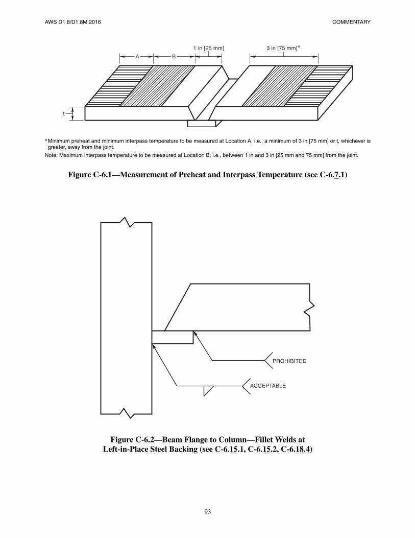
AWS D1.8/D1.8M:2016 COMMENTARY
93
a Minimum preheat and minimum interpass temperature to be measured at Location A, i.e., a minimum of 3 in [75 mm] or t, whichever isgreater, away from the joint.
Note: Maximum interpass temperature to be measured at Location B, i.e., between 1 in and 3 in [25 mm and 75 mm] from the joint.
Figure C-6.1—Measurement of Preheat and Interpass Temperature (see C-6.7.1)
Figure C-6.2—Beam Flange to Column—Fillet Welds atLeft-in-Place Steel Backing (see C-6.15.1, C-6.15.2, C-6.18.4)
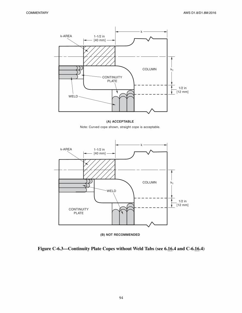
COMMENTARY AWS D1.8/D1.8M:2016
94
Figure C-6.3—Continuity Plate Copes without Weld Tabs (see 6.16.4 and C-6.16.4)
AWS D1.8/D1.8M:2016
95
C-7. Inspection
C-7.1 Inspection Task AssignmentQuality Assurance (QA) consists of those inspection services to be performed by an agency or firm other than the Con-tractor. QA is performed at the prerogative of the Owner and may be mandated by the building code. QA includes mon-itoring of the performance of the Contractor in implementing the Contractor’s QC program, ensuring that designated QCfunctions are performed properly by the Contractor on a routine basis. To ensure compliance, QA may also include per-formance of specific inspection tasks that may be similarly included in the Contractor’s QC plan, including performanceof nondestructive testing. Quality assurance is termed “verification inspection” in AWS D1.1/D1.1M.
Quality Control (QC) includes those functions to be performed by the Contractor to ensure that the material and work-manship of construction meet the quality requirements. QC includes inspection and testing of fabrication and erection asdefined by AWS D1.1/D1.1M, unless otherwise provided for in the Quality Assurance Plan or the Contract Documents.Fabrication and erection inspection include routine welding inspection items such as personnel control, material control,preheat measurement, monitoring of welding procedures, and visual inspection. Quality control is termed “Contractor’sInspection” in AWS D1.1/D1.1M.
The Engineer is to provide the QAP as part of the Contract Documents (see C-1.4.1 Item 13). The AISC Seismic Provi-sions, Chapter J includes the minimum requirements for a QAP as applied to welded steel construction in the SFRS. Itmay be appropriate to adjust these requirements based on the skill and practices of the parties involved. It is essentialthat the Contract Documents define these requirements.
C-7.2 Inspector QualificationsC-7.2.1 QA Welding Inspector Qualifications. The inspector should be familiar with this code and AWS D1.1/D1.1M,Structural Welding Code—Steel.
C-7.2.4 UT Technicians. Ultrasonic technicians are typically certified by the employer in accordance with ASNTguidelines (SNT-TC-1A). Requirements for Level II certification can vary significantly between organizations, andASNT Level III technicians are not required to perform a hands-on practical test, therefore Annex F provides a rigorousqualification appropriate for this work. Annex F requires a practical examination using weld mockups with known flawswith an evaluation procedure similar to API RP 2X for offshore structures.
Research and SAC/FEMA studies have shown a wide variation of ultrasonic testing (UT) personnel skills for flaw detec-tion using current AWS D1.1/D1.1M Part F procedures. Annex F provides a practical examination to determine the UTtechnician’s ability using mockups of joints similar to project conditions. It is anticipated that all UT technicians would,as a minimum, be qualified for AWS D1.1/D1.1M Part F procedures for Flaw Detection. It is recommended that thirdparty organizations be used to conduct examinations of UT technicians. The mockups with representative flaws, used forexamination, are expensive and difficult to fabricate. Third party examination could provide objective, comparable, andconsistent testing with potential to use same mockup samples for many examinees.
COMMENTARY AWS D1.8/D1.8M:2016
96
C-7.3 Quality Assurance Agency Written Practice
QA Agencies should have internal procedures (Written Practices) that document how the Agency performs and docu-ments inspection and testing in accordance with ASTM E329, Specification for Agencies Engaged in the Testing and/orInspection of Materials Used in Construction.
C-7.4 Wide-Flange k-Area Inspection
See C-4.1. This k-area cracking has been found to manifest itself in a delayed manner. Cracking of the base metal typi-cally occurs 24 hours to 48 hours after welding. The cracks generally, but not always, penetrate the thickness of the basemetal. For doubler plates, where welding in the k-area is performed, MT in the k-area should be performed on the side ofthe member web opposite the weld location, and at the end of the weld. If both sides of the member web receive doublerplates in the k-area, MT of the member web should be performed after welding of one side, prior to welding of the oppo-site side.
C-7.5 Lamellar Tearing
Lamellar tearing is the separation (tearing) of base metal along planes parallel to rolled surface of a member. The tearingis the result of decohesion of “weak planes,” usually associated with elongated “stringer” type inclusions. If and whenlamellar tears occur, they generally are the result of the contraction of large weld metal deposits under conditions of highrestraint in the through thickness (short transverse) direction of the base metal. Planes of near-surface stringer inclusionsreduce the effective strain-resisting thickness of the base metal. Lamellar tears characteristically exhibit a “stair-step”appearance, as the crack propagates by decohesion of inclusion and metal, in the rolling direction; and by ductile shearfrom inclusion plane to inclusion plane in the short transverse direction.
In general, the type, size, location, and distribution of nonmetallic inclusions govern the base metal’s lamellar tearingsusceptibility. Susceptibility increases with increasing inclusion density, size, and proximity to the surface where shrink-age strains develop. Typically inclusions located deeper from the surface than t/4 do not contribute to lamellar tearingsusceptibility.
AISC Seismic Provisions requires UT inspection of base metal that is thicker than 1-1/2 in [40 mm], loaded in tension inthe through thickness direction (due to weld shrinkage strains) in tee and corner joints, where the connected material isgreater than 3/4 in [20 mm] and contains CJP groove welds. The IBC contains similar provisions. Inspection of thinnerbase metal loaded in the through thickness direction is typically not justified. AWS D1.1/D1.1M Table 6.2 criteria aretypically applied to weld metal, not base metal. This criteria has been deliberately selected as a conservative acceptancecriteria for members of the SFRS. Whether the detected discontinuities existed before welding (e.g., laminations), orwhether the result of weld shrinkage strains (e.g., lamellar tearing) is immaterial in terms of this provision: all disconti-nuities within the applicable inspection zone are to be accepted or rejected based upon AWS D1.1/D1.1M Table 6.2.
C-7.6 Beam Copes and Weld Access Holes
Finite element studies have shown that the stress flow near and around weld access holes is very complex, and stress lev-els are very high, even for properly made access holes. Notches can further amplify this stress level even higher, and canlead to cracking from the access hole. Cracking from access holes was occasionally observed in the Northridge earth-quake, and was commonly observed in the Great Hanshin (Kobe) earthquake. The surface of the weld access hole mustbe smooth. Surface defects must be found and preferably removed by grinding (see 6.11.2). Both PT and MT are capableof detecting unacceptable surface cracks. AISC Seismic Provisions requires that at welded splices and connections, ther-mally cut surfaces of weld access holes be inspected when the flanges thickness exceeds 1-1/2 in [40 mm] for rolledshapes, or when the web thickness exceeds 1-1/2 in [40 mm] for built-up shapes.
AWS D1.8/D1.8M:2016 COMMENTARY
97
C-7.10 Ultrasonic TestingC-7.10.2 Acceptance Criteria—Flaw Detection. The use of alternative techniques other than those prescribed by AWSD1.1/D1.1M Clause 6 may provide further information regarding the size, location, and nature of embedded weld flaws.To evaluate the results of such alternative techniques, it is necessary to calibrate the equipment and techniques usingstandard reflectors to establish a Standard Sensitivity Level (SSL) and Disregard Level (DRL), and use these values aswell as the measured length of the discontinuity to establish the acceptability of the weld.
C-7.10.3 Unacceptable Welds. The flaw sizing methods prescribed in Annex H may permit the acceptance of weldflaws that would otherwise be unacceptable. Weld repair procedures are based on AWS D1.1/D1.1M 5.25 as well as thegeneral requirements of this standard. The decision to accept otherwise rejectable welds using flaw sizing techniques isbased on the rationale that the repair may cause more damage than the defect.
Other acceptance criteria may be considered on a case-by-case basis when all the defect parameters are known and afracture mechanics analysis is performed. It is essential to know the following:
(1) the defect size, orientation, and type in the welded joint, with sufficient accuracy,
(2) the base metal and weld metal mechanical properties, predicted with sufficient accuracy, and
3) the design stress condition with due consideration for the predicted level of residual stress level and distribution.
Finally, the design stress condition relative to the predicted level of residual stress must be determined.
C-7.10.4 Left-in-Place Steel Backing. A properly made weld with left-in-place steel backing will result in a variety ofUT reflections that may be misinterpreted as a weld defect. Alternately, UT signals from true weld defects may be inad-vertently ignored, being interpreted to be a reflection from backing (see AWS Dl.l/Dl.lM C-6.25.12 for discussion ofthese issues).

This page is intentionally blank.
AWS D1.8/D1.8M:2016
98
AWS D1.8/D1.8M:2016
99
C-Annex A
WPS Heat Input Envelope Testing ofFiller Metals for Demand Critical Welds
C-A1. Purpose
Heat input affects weld metal and HAZ cooling rates. Higher levels of heat input reduce cooling rates. Heat input alsoaffects weld bead sizes, with higher levels of heat input creating larger weld beads. Both cooling rates and bead size mayaffect mechanical properties, and CVN toughness may be significantly changed with variations in heat input. By testingat a high and low heat input level, an “envelope” is created. Production WPSs may utilize any combination of weldingvariables that result in a computed heat input that is not greater than the high heat input test limit, or less than the lowheat input test limit. It is expected that heat input levels between these limits will result in acceptable mechanical properties.
Tensile and elongation results obtained from welds made with heat input values between the high and low limits willlikely be bracketed by the values obtained in the high and low heat input tests. CVN toughness tends to deteriorate atboth high and low heat input levels; values obtained from welds made with heat input values between the high and lowlimits will likely be greater than the values obtained at the extremes.
The annex applies only for filler metals to be used for Demand Critical welds. Filler metals used to make other weldscovered by this code are not required to be tested in accordance with this annex.
C-A2. Testing Procedure
The heat input limits listed in Table A.1 are merely suggestions and deviation from these values is possible. The sugges-tion was made in order to encourage some commonality between the limits selected by various filler metal manufactur-ers, and others that might do such testing. Some filler metals may not be capable of delivering the required mechanicalproperties at the suggested heat input levels; under such conditions, it is acceptable to use a tighter range of heat inputvalues, providing the production WPS computed heat input values are within the tighter ranger. Further, if a broaderrange is desirable, the use of the larger range is possible in production, providing acceptable results have been obtainedin testing in accordance with this annex. The use of heat input limits outside the bounds of Table A.1 are acceptableunder this code, provided the higher limits have been successfully tested.
C-A3. Preheat and Interpass Temperature
Preheat and interpass temperatures may affect the mechanical properties of deposited weld metal. Testing according tothis annex requires the preheat and interpass temperatures be within the prescribed ranges. These are not minimum val-ues; the preheat and interpass temperatures are to be held within the prescribed limits shown in Table A.1. Productionpreheat and interpass temperature controls are to be in accordance with this code and AWS D1.1/D1.1M, and will likelynot be the same as the limits of Table A.1.
COMMENTARY AWS D1.8/D1.8M:2016
100
C-Table A-1See C-A5.2.
C-A5. Welding of Test PlateThe test assembly may be restrained, or the plates preset in advance of welding in order to preclude rejection of the testassembly due to excessive warpage (see A5.3). The annex does not specify the position in which welding of the testplates is to be done. In general, from a practical viewpoint, this will typically be done in the flat position. For filler met-als designed for vertical up welding, flat position welding may be difficult. It is not the intent of this annex to requirequalification of filler metals in all positions in which welding will be performed. It is acceptable to use the resultsobtained in a flat position test to justify the use of the filler metal in the overhead position, for example.
C-A5.2 Heat Input. For the low heat input test, it will likely be necessary to allow the test plate to cool between passesin order for the test plate to achieve the prescribed interpass temperature. For the high heat input test, it may take severalweld passes before the interpass temperature is achieved. This is acceptable, so long as the welding operations are notinterrupted. Welding operations include cleaning of the weld, measuring interpass temperatures, etc. If welding opera-tions are interrupted and the interpass temperature drops below the prescribed limit, welding is not permitted to resumeuntil the interpass temperature is achieved.
Heat input is calculated by the following formula: H = 60 E I/S where H = heat input, E = arc voltage, I = current, and S= travel speed. When travel speed is measured in inches per minute [mm per minute], heat input will be expressed inunits of Joules per inch [Joules per mm]. For welding procedures using two or more electrodes in one weld pool, heatinput is the sum of the heat inputs calculated from the voltage and current from each power source if more than onepower source is used. If a single power source is used, the heat input is calculated from the voltage and current from thatpower source. Some variation in heat input rates during the fabrication of the test plate is expected due to changes in thethree variables that determine heat input. Variations in these variables are permitted so long as the total change to thecomputed heat input is not greater than 20% from the nominal value.
In the 2005 edition of D1.8/D1.8M, except for the root pass, a minimum of two passes per layer were required to fill thetest plate. This provision was deleted from the code. Experience showed this provision was difficult or impossible toachieve with high heat input conditions. It was deemed acceptable to use single passes per layer since achieving accept-able results under such conditions is typically more difficult than when split layers are used. Production welds are to bein accordance with AWS D1.1/D1.1M limitations on weld layer thickness and split layer requirements.
C-A7. Acceptance CriteriaC-A7.1 Strength and Ductility Requirements. The tensile strength data obtained from the all weld metal tensile testspecimens are all minimum values, with no maximum values specified. These criteria have been determined to be suffi-cient for acceptable performance of connections covered by this code. This code is not applicable to situations wherefiller metal of a strength level greater than that of an E90 [E62] filler metal is required. All tensile testing is done at roomtemperature, regardless of LAST, if specified.
C-A7.2 CVN Toughness Requirements. For applications where Contract Documents have specified a LAST for struc-tures not normally maintained at 50°F [10°C] or higher, the testing temperature for CVN testing is required to be LAST,plus 20°F [10°C] for welds using 70 ksi [490 MPa] or 80 ksi [550 MPa] filler metals and LAST for welds using 90 ksi[620 MPa] filler metals. For other applications, testing is done at 70°F [20°C] for welds using 70 ksi [490 MPa] or 80 ksi[550 MPa] filler metals and 50°F [10°C] for welds using 90 ksi [620 MPa] filler metals. (see 6.2.2).
AWS D1.8/D1.8M:2016
101
C-Annex B
Intermix CVN Testing of Filler Metal Combinations(where one of the Filler Metals is FCAW-S)
C-B1. PurposeThere have been instances that even though each filler metal individually was classified as having adequate notch tough-ness, the mixing process during the completion weld resulted in a combined weld with reduced notch toughness. Thisannex is intended to ensure that unacceptable degradation does not take place.
This testing is to be performed when required by 6.1.4. The only filler metal combinations required to be tested are thosewhere one of the two is FCAW-S. Combinations of FCAW-S with FCAW-S may be used without performing this test-ing. Any combinations of SMAW, FCAW-G, GMAW, SAW, or ESW may be used without performing this testing (seealso C-6.1.4).
C-B2. Filler Metal VariablesAnnex B and Tables B.1 and B.2 require that every combination of welding process be checked for suitability when oneof the welding processes is FCAW-S. However, depending on the positioning of the weld deposited with the other pro-cess (substrate/root versus fill), not every combination of manufacturer, brand name and trademark, and diameter mustbe checked. For example, a single test with GMAW substrate and a specific FCAW-S electrode (AWS ClassificationManufacturer, Manufacturer Brand and Trademark, and diameter) will qualify that specific FCAW-S electrode for usewith GMAW electrode of the same AWS Classification, regardless of the Manufacturer, Manufacturer’s Brand andTrademark, or diameter of GMAW electrode. Tables B.1 and B.2 do not require testing of every combination shown(e.g., FCAW-G and SMAW), but is applicable only when one of the two processes is FCAW-S (see C-B1).
C-B4. Welding of Test PlateThe order of deposit affects the resultant properties. If in production, FCAW-S is to be used first, and FCAW-G placedover the FCAW-S, the test plate must have FCAW-S in the root, and FCAW-G used to fill the joint. Substitution of testsperformed in the opposite sequence is not permitted.
The substrate/root material may be a root pass, tack weld, or in the case of a weld repair, the original material used tomake the weld joint. The fill material may be a weld process that is different from that used for tack welding, or for mak-ing the root pass. The fill material may also represent the materials used to repair defective welds.
The welding parameters used to weld the intermix test plate assembly are not restricted. Any combination of weldingvariables may be used, including any heat input level. It is not necessary to perform intermix testing with high and lowheat input levels. It is generally advantageous to use welding parameters similar to those used for the AWS A5 specifica-tion filler metal classification test, although such parameters are not a code requirement for the intermix test.
COMMENTARY AWS D1.8/D1.8M:2016
102
C-B5. Test Specimens RequiredWhile yield and tensile strength, as well as elongation, may be slightly affected by intermixing of welding processes, itis the CVN impact properties that may be more significantly affected. Accordingly, only CVN properties must be tested.When testing is being performed for welds governed by this code, but not to include Demand Critical welds, only fiveCVN specimens are required. These are tested at 0°F [–18°C] or –20°F [–30°C]. When testing is being performed forDemand Critical welds, one set of five specimens is prepared for testing at 0°F [–18°C] or –20°F [–30°C], and anotherset of five is prepared for testing at 70°F [20°C] or 50°F [10°C]. A single set of five specimens may be used to satisfyboth the lower temperature requirement for all welds governed by this code, as well as the higher temperature require-ment for Demand Critical welds, providing the testing performed at the lower temperature demonstrates an absorbedenergy level no less than 40 ft·lbf [54 J]. It is possible, however, that a weld deposit may be able to achieve the requiredenergy at the required test temperatures but not be able to achieve the energy required for the higher test temperaturewhen tested at the lower test temperature.
C-B6. CVN Specimen LocationThe weld metal deposited by the second process is the material of interest. Ideally, the specimens would include only thematerial from the interface region and the second process material. The region that is nearest the first process welddeposit is expected to be the material that is most affected. This may be a small region. It is important that the CVNspecimen be accurately located so that this small region is contained within the test region of the CVN specimen.
Due to chemistry differences between FCAW-S and other weld metals, etching of the deposit easily reveals the interfaceof the two weld deposits.
C-B7. Acceptance Criteria—All WeldsThis testing temperature is not subject to revision by 6.2.2.
C-B8. Acceptance Criteria—Demand Critical WeldsFor applications where Contract Documents have specified a LAST for structures not normally maintained at 50°F[10°C] or higher, the testing temperature for CVN testing is required to be LAST, plus 20°F [10°C] except for E90 [E62]filler metals where the test temperature is equal to the LAST. For other applications, testing is done at 70°F [20°C] (see6.2.2).
AWS D1.8/D1.8M:2016
103
C-Annex D
Supplemental Welder Qualificationfor Restricted Access Welding
C-D1. Purpose
See 5.1.1. This test is required to be taken and passed by all welders who make Demand Critical beam-to-column flangegroove welds on structures governed by this code when such welding requires that welds be made through a weld accesshole. This is typically the situation of the bottom flange connection of an I-shaped beam that frames into a column.These tests are not required for any weld that is not governed by this code, is not part of the SFRS, or when welding isnot performed through an access hole.
This annex is used to qualify welders for flat position groove welding. It is also used to qualify welders when nonsteelbacking is used, or when open root groove welds are used. AWS D1.1/D1.1M welder qualification tests, not the testsdescribed in this annex, are used to qualify the welder for overhead welding.
Welders previously qualified, within the time limit restrictions, using similar restricted access plate tests, should beaccepted based on those tests.
C-D3. Test Plate Fabrication
C-D3.1.1 Test Plate Assembly. The basic test assembly may be assembled by an individual other than the welder beingqualified. Attachment of the weld tabs must be done by the welder. Improper attachment of the weld tabs, and the result-ant poor weld quality at the end of the weld, may affect the performance of the bend specimens.
C-D3.1.2 Welding Procedure Specification. The ability of the welder to control weld metal deposited at high deposi-tion rates is an essential ingredient of this test. Typically measured in pounds of deposited metal per hour [kilograms perhour], the deposition rates can be directly determined by measuring the time it takes to deposit a weld of a known weight(mass). More frequently, deposition rates are determined by using a welding current/deposition rate chart, or a wire feedspeed/deposition rate curve. For SMAW, melt off rates may be used. Any method of measurement of deposition rate isacceptable for this test.
A welder that is capable of depositing a quality weld at, for example, 10 lbs [4.5 kg] per hour, may have great difficultymaking the same weld at 20 lbs [9 kg] per hour.
Deposition rates are measured based on 100% arc time, that is, only the welding time is measured. The nonwelding time(cleaning the weld, etc.) should not be considered when deposition rates are measured.
C-D3.1.4 Test Specimen Preparation. Identification of the location of the web plate is important as it is from withinthe 1 in [25 mm] region under the web that the center two bend specimens must be removed.
COMMENTARY AWS D1.8/D1.8M:2016
104
C-D3.2 Option A. A welder qualified in accordance with Option A may weld on different joint details in production(e.g., different root openings, included angles), and the WPSs may vary as well, so long as the same process is used, andthe deposition rate used in production does not exceed that used in the qualification testing.
C-D3.2.2 Groove Weld Detail. The groove weld detail prescribed by this provision is used to qualify the welder for anygroove weld geometry to be used in production. The groove and access hole geometry used in the test does not restrictgroove and access hole geometry used in production. No other geometry may be used for the Option A test.
C-D3.2.4 Backgouging and Back Welding. The backgouged cavity must be restored with weld metal. The qualifica-tion test described in this annex does not require that the welder specifically demonstrate his/her skills with all the weld-ing processes that may be used for back welding. Welder qualification to AWS D1.1/D1.1M is sufficient. Thus, for thetest described in this annex, any process or procedure may be used for the back welding operation.
C-D3.3 Option B. The backing and groove details used for Option B are not prescribed in this annex, but are ratherrequired to be representative of the most demanding conditions that will be encountered in production. Successful quali-fication with a test in accordance to Option B permits the welder to weld with the same process, and same backing type,within limitations on variations in the joint details. Separate testing is required for copper, versus ceramic, versus openroot joints. If steel backing is used, qualification per Option A is required.
C-D3.3.1 Backing, Root Condition, and Groove Weld Details. The test plate is intended to duplicate not only the typ-ical conditions that will be encountered in production, but the most demanding conditions. D3.3.4 restricts the welderfrom welding in production joints that are larger in root opening, and tighter in the included angle, than the conditionused for qualification testing. Accordingly, it is advisable to fit up the test plate with the application of tolerances thatwill yield the greatest production flexibility (see D3.3.4 and C-D3.3.4).
C-D3.3.3 Backgouging and Back Welding. The Supplemental Welder Qualification for Restricted Access Welding—Option B test does not require that the weld root be backgouged and back welded before the testing required by ClauseD4 is performed. However, at the Contractor’s discretion, the welder has the option of backgouging the weld root. Thismay be desirable when root imperfections are observed or suspected. If this option is used, then the backgouging andback welding must be performed by the welder being qualified, and such welding must be done in the overhead position.
C-D3.3.4 Option B Limitations. For joints that are backed by copper and ceramic, as well as for open joints (e.g., nobacking), a more demanding condition is created when the root opening is increased, and the included angle isdecreased. This provision requires that the welder demonstrate his/her skills under the hardest-to-weld root conditions.When the test plate is constructed, the restrictions of this provision should be considered (see D3.3.1 and C-D3.3.1).
C-D4. Specimen Testing
C-D4.2.1.1 Specimen Locations. The full thickness of the two bend specimens taken from the center of the weld mustbe taken from the 1 in [25 mm] length of the weld that was directly under the web plate. The outboard bend specimens,taken from the ends of the welds, measure the ability of the welder to make sound welds along the complete length of theweld. The side of the bend specimen nearest to the end of the weld is the region that will most likely contain weld dis-continuities. It is this face of the bend specimen that is to be strained most severely during the bend test (e.g., this sidewill become the convex side of the bend specimen).
C-D4.2.3 UT Inspection. The use of cyclic criteria for welder qualification using UT is based upon the use of cyclic cri-teria when performing RT for this purpose in AWS D1.1/D1.1M 4.22.3. It is not intended to reflect any need for cycliccriteria for the production weld.
C-D.5 Retesting
Welders who fail the test described in this annex are permitted to perform other welds governed by this code where thisqualification test is not required.
AWS D1.8/D1.8M:2016
105
C-Annex E
Supplemental Testing for Extended ExposureLimits for FCAW Filler Metals
C-E1. PurposeThe supplemental testing prescribed in the annex is not required to be performed for filler metals used for any processother than FCAW. Testing described in the annex is not required to support the standard 72-hour period, but is requiredwhen this time period is extended.

This page is intentionally blank.
AWS D1.8/D1.8M:2016
106
AWS D1.8/D1.8M:2016
107
C-Annex F
Supplemental Ultrasonic Technician Qualification
C-F3. Test SpecimensC-F3.4 Confirmation and Categorization of Flaws. The test specimens for these examinations must be accuratelycharacterized before being used to qualify UT technicians. A number of NDT procedures may be used, including angleRT, to fully characterize the specimen flaws. Examination by multiple qualified people can also provide assurance ofspecimen flaw locations.
C-F3.7 Number of Test Plates. Eight to ten different test plates, 18 in to 24 in [460 mm to 610 mm] in length, with atotal of twenty or more “flaws” should provide an adequate test of ability. Typical time for these tests is 4 hours to 6hours.

This page is intentionally blank.
AWS D1.8/D1.8M:2016
108
AWS D1.8/D1.8M:2016
109
C-Annex G
Supplemental Magnetic Particle Testing Procedures
This annex is similar to API RP2X with some simplifications. It is based on using the yoke method with dry visible par-ticles as this is the typical method used by NDT practitioners in the building construction industry. Other techniquessuch as prods and more sensitive methods are typically not warranted and may only be used if approved by the Engineer.
C-G10. Yoke PlacementC-G10.2 Detection of Longitudinal Discontinuities. The effective area of inspection is between the yoke legs, with a lat-eral area of approximately 1/2 of the yoke leg spacing. The total length weld coverage for one position of the yoke isapproximately 3 in [75 mm]. Yoke movement in 3 in [75 mm] intervals should ensure adequate overlap.
C-G10.3 Detection of Transverse Discontinuities. The effective area of inspection is between the yoke legs, with a4 in [100 mm] leg spacing recommended. Sufficient overlap may be achieved by moving the yoke to a position whichoverlaps the last position by at least 1 in [25 mm].
C-G12. Interpretation and Evaluation of IndicationsFalse indications are those held primarily by nonmagnetic means such as mechanical entrapment in the toe of a weld.Nonrelevant indications are those held in place by magnetic attraction, but not originating from a structural discontinu-ity, such as the boundary of two steels having significantly different magnetic properties or by the hardened heat-affected zone of a weld.

This page is intentionally blank.
AWS D1.8/D1.8M:2016
110
AWS D1.8/D1.8M:2016
111
C-Annex H
Flaw Sizing by Ultrasonic Testing
C-H1. Flaw SizingThere may be specific situations where the use of highly advanced techniques for UT may be implemented, typicallywhen the repair of a weld would be particularly difficult to access or perform, or when the repair may result in moreharm to the joint than benefit. Such techniques require specialized knowledge and skills, and in some cases equipment,not commonly found among industry UT technicians.
These techniques can provide sufficient information for the application of fracture mechanics evaluation of a particulardiscontinuity or joint. The acceptance criteria provided was developed using a fracture mechanics approach, assuming aweld CVN toughness of 40 ft·lbf [54 J] at 70°F [21°C]. (References: FEMA 355B, State of the Art Report on Weldingand Inspection, Subclause 7.4, Federal Emergency Management Agency, 2000, and SAC/BD-99/24, Weld AcceptanceCriteria for Seismically-Loaded Welded Connections, W. Mohr, 1999.)

This page is intentionally blank.
AWS D1.8/D1.8M:2016
112
AWS D1.8/D1.8M:2016
113
AAcceptance criteria
air velocity, 6.6.3demand critical welds, 3, B8, C-A7, C-B8flaw detection, see Ultrasonic testingflaw sizing, see Ultrasonic testingheat input envelope testing, A7.1, A7.2intermix of FCAW-S filler metal, 6.1.4, B7, B8, C-B7lamellar tearing, C-7.5macroetch specimen, 4.3.1nongas shielded processes, 6.6.3.2quality control and quality assurance, C-1.1strength and ductility requirements, A7.1supplemental magnetic particle testing, G2, G13supplemental welder qualification, D4.2.1.3supplemental ultrasonic technician qualification, F3.3ultrasonic testing (UT), 7.10.2, C-7.10.2ultrasonic testing (UT) flaw sizing, H1, H2, C-H1unacceptable welds, 7.10.3, C-7.10.3
Access holes, C-6.9alternate geometry, 6.11.1.2AWS D1.1/D1.1M geometry, 6.11.1.1AWS standards, 1.4.1, C-1.4.1bottom flange welding sequence, 6.9demand critical welds, 6.11Engineer’s responsibilities, 1.4.1grinding, C-4.1inspection, 7.6, C-7.6notches and gouges, 6.11.2.2quality requirements, 6.11.2repair inspection, 7.7repair in the protected zone, 7.7repair of notches, 6.11.2.3, C-6.11.2.3shape (geometry), 1.4, 6.11.1, C-6.11.1.1special geometry, 6.11.1.3, C-6.11.1.3surface roughness, 6.11.2.1
Air carbon arc gouging, 6.13, 6.16.3, 6.18.3. See also Backgouge
Air velocity limits, 6.6.3, C-6.6.3.1, C-6.6.3.2AISC (American Institute of Steel Construction)
access holes, 6.11.1, C-6.11, C-7.6scope of AWS D1.8/D1.8M, 1.1, C-1.1
attachments and welds, C-6.15backing, Table C-1.1CVN requirements, C-6.1definitions for seismic provisions, C-3demand critical welds, C-3demand critical welds processes, 6.5, C-6.5Engineer’s responsibilities, C-1.4FEMA requirements, C-6.1k-area, C-4.1prequalified connections, C-1.4.1protected zone, C-3, C-6.18quality assurance plan (QAP), C-3, C-7.1seismic force resisting system (SFRS), C-3.1seismic provisions, 6.5.1, C-1.1, C-1.4.1standards, 2UT inspection of base metal, C-7.5
All weld metal tensile test, A5.4, A6, A7.1, C-A7.1Arc spot welds (puddle welds), 6.18.1ASME (American Society of Mechanical Engineers),
6.3.1.2
BBacking
backgouging and back welding, D3.2.4, D3.3.3ceramic, D3.2.5, D3.3, D3.3.4, C-5.1.3, C-D3.3.4copper, D3.3, D3.3.4, C-5.1.3dimensions, Fig. D.1Engineer’s responsibilities, 1.4fillet welds, 1.4.1, 6.14, 6.15, C-1.4.1, C-6.14, C-6.15,
Fig. C-6.2fillet weld size, C-6.15.1flaw sizing, H2.3fusible, 6.13, C-6.12.3gouging, C-6.13groove welds, 6.12.3heat input envelope testing, A4nonfusible, 5.1.3, 6.13, D3.3, D3.3.2, D3.3.3notch effects, C-6.13prohibited welds, 6.15.2, 6.18.1, C-6.15.2, C-6.18.1protected zone, 6.12.3, C-6.12.3
Index
INDEX AWS D1.8/D1.8M:2016
114
removal, 1.4.1, 6.13, D3.2.3, D4.2, C-1.4.1, C-6.13, Table C-1.1
repairs, 6.18.4root condition and groove weld details, D3.3.1steel, 1.4.1, 6.12.3, 6.14, 7.10.4, A4, D3.2.1, D3.2.5,
C-6.12.3steel, left-in-place, C-7.10.4steel, prohibited welds on left-in-place, 6.15.2supplemental ultrasonic technician testing, F3tack welds, 6.12.3, C-6.12.3test specimens, F3.1ultrasonic testing (UT), 7.10.4, C-6.13, C-7.10.4welder qualifications, 5.1.3, 5.3, D3.2.1, D3.2.3,
D3.2.4, D3.3, D3.3.4, C-5.1, C-D1, C-D3.3, C-D3.3.1, Fig. D.1
Backgouge, 6.13, D3.2.4, D3.3.3, C-6.13, C-D3.2.4, C-D3.3.3
Back welding, 6.13, C-D3.2.4. See also Reinforcing fillet welds and Fillet welds at left-in-place steel backing
Baking, 1.4.2.3, E4.3, C-1.4.2.3Beam copes, 7.6, C-4.1. See also CopesBend tests, D4.2, D4.2.1, D4.2.1.1, C-D3.1.1,
C-D4.2.1.1, Fig. D.4Bottom flange welding sequence, 6.9, C-6.9
CCanadian Welding Bureau (CWB), 7.2.1Ceramic backing, D3.2.5, D3.3, D3.3.4, C-5.1.3,
C-D3.3.4Certification/Certificate of conformance, 1.4.2.1, 1.4.2.2,
6.1.2, 6.3.1.3, C-1.4.2.4Certified Associate Welding Inspector (CAWI), 7.2.1,
7.2.3Certified Welding Inspector (CWI), 7.2.1Continuity plates
bottom flange welding sequence, 6.9clips, 4.1, C-4.1corners, C-6.16.1MT requirements, 7.4weld tabs, 6.16.4, C-6.16.4, Table C-1.1, Fig. C-6.3
Contract documentsaccess holes geometry, 6.11, C-6.11AISC seismic provisions, C-1.1, C-1.4.1demand critical welds, 3, C-3Engineer’s responsibilities, 1.4.1, C-1.4.1filler metal classification properties, C-6.1, C-Table
6.1fillet weld at left-in-place backing, C-6.15.1inspection, 7.1LAST, C-A7protected zone, 3
quality assurance plan (QAP), 3, 7.1, C-7.1seismic force resisting system (SFRS), 3tab removal, 6.16.3
Copesbeam, 7.6, C-4.1plate, Fig. C-6.3
Copper backing, see Backing, nonfusibleCorner clips of continuity plates and stiffeners, 4.1,
C-4.1, Fig. C-4.2. See also Continuity platesCorner clips, 4.1.1, 4.1.2, 4.1.3, C-4.1Curved corner clips, 4.1.4, C-4.1, Fig. C-4.1CVN filler metal intermixing, 6.1.4, Annex BCVN toughness, 2, 6.3.1.2, 6.7.2, C-4.1, C-6.1, C-6.2.1,
C-6.6.3.1, C-6.6.3.2, C-Annex A, C-A1, C-A7, C-Annex B, C-B5, C-B6, C-B8, C-H1, C-Table 6.1
CVN toughness requirements, A7.2, B7, Tables 6.1 and 6.2, Table A.2, C-A7.2
mandatory, Annex B, C-6.6.3.1
DDams. See End dams“-D” designator, 6.2.1(3), 6.2.1(4), 6.2.1(5), 6.2.1(6),
6.3.1(2), 6.3.1(3), 6.8.1(2)filler metal production lot control, 6.3.1heat input limits, 6.8.1test plate, 6.2.1WPS heat input envelope testing properties, 6.2.1,
C-6.2.1Definitions, 3, C-3Demand critical welds, 6.1, C-6.1
acceptance criteria, B8, C-B8approved welding processes for, 6.5.1, C-6.5.1certification of heat input envelope testing, 1.4.2.2CVN requirements, C-6.1.1. See also CVN toughness
requirementsdefinitions, 3, C-3designation of, 1.4.1diffusible hydrogen level, 6.1.3, C-6.1.3, Table 6.3FCAW electrode packaging storage and exposure, 6.4,
C-6.4filler and weld metal, 6.1filler metal classification properties, Table 6.1,
C-Table 6.1filler metal production lot control, 6.3.1, 6.3.1.2heat input envelope, 6.2.1, C-6.2.1heat input limits, 6.8.1intermix CVN testing, Annex B, B8, C-B5, C-B8lowest anticipated service temperature (LAST)
applications, 6.2.2, C-6.2.2mechanical properties for, Table 6.2overexposed FCAW electrodes, 6.4.4, C-6.4.4packaging condition for electrodes, 6.4.1
Backing (Cont’d)
AWS D1.8/D1.8M:2016 INDEX
115
protected zone, Figs. C-1.1, C-1.2, and C-1.3required tests, 5.1.1supplemental welder qualification for restricted access
welding, Annex D, C-Annex Dsupplemental welder qualification testing
documentation, 1.4.2.7testing source, 6.2.3test specimens required, C-B.5weld access holes, 6.11, C-6.11welding procedure specifications (WPSs), 6.6, C-6.6WPS content, 6.6.2WPS heat input envelope testing of filler metals for,
Annex A, C-Annex A, C-A1WPS heat input envelope testing properties, 6.2.1,
C-6.2.1, Annex ADepartment of defense, 6.3.1.2(4)Deposition rate, D3.1.2
maximum, 5.3, C-6.6Option A limitations, D3.2.5, C-D3.2supplemental welder qualification, 5.1.2, C-5.1.2testing parameters, 5.1.2, C-5.1.2welding procedure specification (WPS), D3.1.2, C-6.6,
C-D3.1.2Diffusible hydrogen
alternate atmospheric exposure criteria, E4.1electrode certification, 6.1.2extended electrode exposure, C-1.4.2.5FCAW electrode heating, baking, and rebaking, 6.4.2,
6.4.3, E4.3level, 6.1.3, C-6.1.3, Table 6.3maximum, 6.4.1, C-6.4.1requirements for testing, Table 6.3storage and atmospheric exposure, E4.2supplemental testing for extended exposure limits for
FCAW metals, E3, E3.2, C-E1testing procedures, E3.2, Table 6.3
Diffusible hydrogen level, 6.1.3, Table 6.3FCAW, C-6.1.3
Drying, 6.4.2, 6.4.4, C-6.4.4Ductility, A1, A7
air velocity and loss of shielding impact on, 6.6.3.1, C-6.6.3.1
requirements, A7.1, C-A7.1WPS heat input envelope testing, A1, 6.2.1, C-6.2.1
Dye penetrant testing (PT), 7.6, 7.7, C-7.6
EEdge blocks, D4.2.2EGW, Table 6.3, C-1.4.2.3, C-6.5.1Electroslag welding (ESW). See ESW (electroslag
welding)End dams, 6.17, C-6.17
acceptable and unacceptable use of, Fig. 6.4described, C-6.17material, C-6.17placement, 6.17.2, C-6.17
Engineeralternative test approval, 6.1.4demand critical welds, 3documentation, 1.4.2EGW with composite electrodes, Table 6.3erection aids, 6.18.2, C-6.18.2ESW, Table 6.3intermix, 6.1.4(3), C-6.1.4LAST, C-6.2.2protected zone, 3quality assurance plan (QAP), 3, 7.1quality assurance plan (QAP) approval, 6.3.1.2(5)repair, 6.18.6, 6.18.8responsibilities, 1.4.1seismic force resisting system (SFRS), 3submittals, 1.4.2tack weld placement, 6.12.2testing source approval, 6.2.3weld access holes surface roughness, 6.11.2.1,
C-6.11.2.1welding process approval, 6.5.1weld tabs for continuity plates, 6.16.4UT acceptance, 7.10.2, 7.10.3
Envelope testing. See Heat input envelope testingEnvironmental conditions
windscreens and shelters, 6.6.3.1, 6.6.3.2, C-6.6.3.1, C-6.6.3.2
wind speed, C-6.6.3.1, C-6.6.3.2Erection aids, protected zone, 6.18.2, C-6.18.2ESW (electroslag welding), C-1.4.2.3, C-6.5.1, C-B1,
Table 6.3Exposure of FCAW filler metals
electrode packaging, storage, and exposure, 6.4, C-6.4exposure time limits for electrodes, E1, 6.4.3, C-6.4.3extended exposure capability of filler metals, 1.4.2.5,
C-1.4.2.5
FFCAW (flux cored arc welding)
air/wind velocity limit, 6.6.3.1, 6.6.3.2, C6.6.3.1, C-6.6.3.2
approved processes for demand critical welds, 6.5.1, C-6.5.1
CVN toughness, 6.6.3.1, 6.6.3.2, Annex B, C-6.6.3.1, C-6.6.3.2, C-Annex B
diffusible hydrogen level, 6.1.2, 6.1.3, C-6.1.3, Table 6.3
electrode packaging, storage, and exposure, 6.4, C-6.4
INDEX AWS D1.8/D1.8M:2016
116
exposure time limits for electrodes, 6.4.3, E1, C-6.4.3, C-Annex E
extended exposure capability of filler metals, 1.4.2.5, C-1.4.2.5
FCAW-S with other welding processes in a single joint, B1, C-Annex B, Table B.1
filler metal details, B2, C-B2filler metal production lot control, 6.3.1.1(3)heat input envelope, 6.2.1(3), 6.2.1(4), C-6.2.1heat input limits, 6.8.1(2), 6.8.1(3a), C-6.6intermix CVN testing of filler metal combinations,
Annex B, C-Annex Bintermix of FCAW-S filler metal, 6.1.4, C-6.1.4joint details for doublers, Fig. 4.3test plate welding, B4, C-B.4test specimens required, B5, C-B.5non gas shielding, 6.6.3.2, C-6.6.3.2notch toughness, B1, C-B1, Tables B.1 and B.2overexposed electrodes, 6.4.4, C-6.4.4packaging condition, 6.4.1, C-6.4.1product data sheets, 1.4.2.3, C-1.4.2.3testing parameters, 5.1.2, C-5.1.2WPS content, 6.6.2, C-6.6WPS heat input envelope testing properties, 6.2.1,
C-6.2.1Filler metal
acceptance criteria, Annex A, C-Annex AAWS A5 specification properties, 6.1.1, C-6.1.1,
Table 6.1, C-Table 6.1certifications, 1.4.2.2, 6.1.2, C-1.4.2.2, C-6.1.2CVN, 6.1, C-6.1, Tables 6.1 and 6.2, C-Table 6.1demand critical, Annex A, C-Annex A, Table 6.2diffusible hydrogen level, 6.1.3, C-6.1.3, Table 6.3exposure limits, 6.2.1, C-6.2.1extended exposure capability, 1.4.2.5, C-1.4.2.5extended exposure limits, supplemental testing for,
Annex E, C-Annex Efor FCAW, E1, C-E1filler metal classification properties, Table 6.1,
C-Table 6.1filler metal details, B2, C-B2heat input envelope, 6.2.1, C-6.2.1, 6.2.3, Annex A,
C-Annex Aheat input limits, 6.8.1, C-6.8.1, Annex A, C-Annex Ahydrogen content, 1.4.2.4, C-1.4.2.4, 6.1.3, C-6.1.3intermix CVN testing of filler metal combinations,
Annex B, C-Annex B, Tables B.1 and B.2intermixing, 6.1.4, C-6.1.4overexposed, 6.4.4, C-6.4.4packaging condition, 6.4.1, C-6.4.1product data sheets, 1.4.2.3, C-1.4.2.3production lot control, 6.3.1, C-6.3.1
production lot testing alternative, 6.3.1.2, C-6.3.1.2production lot testing exceptions, 6.3.1.3, C-6.3.1.3suitability, A1, C-A1supplemental testing for extended exposure limits,
Annex E, C-Annex Etesting parameters, C-A2testing source, 6.2.3test plate details, A4, C-A4welding of test plate, A5, C-A5welding procedure specifications (WPSs), 6.6, C-6.6WPS heat input envelope testing, Annex A, C-Annex AWPS heat input envelope testing properties, 6.2.1,
C-6.2.1Filler metal essential variables
extended exposure limits, Annex E, C-Annex EFCAW-S fill, Annex B, Table B.2FCAW-S substrate/root, Annex B, Table B.1
Fillet welds at left-in-place steel backingbeam flange to column, Fig. 6.2, Fig. C-6.2correction of errors, 6.18.4, C-6.18.4minimum size, 6.15.1, C-6.15.1prohibited welds, 6.15.2, C-6.15.2
Flaw detectionacceptance criteria, 7.10.2, C-7.10.2candidate scoring for, F4examination, F2scoring methodology and formulas, F4.2ultrasonic testing (UT) technicians, 7.2.4, C-7.2.4
Flaw sizingflaw sizing methods and acceptance criteria, 7.10.3,
C-7.10.3technique implementation, H1, C-H1ultrasonic testing (UT), Annex H, C-Annex HUT technician examination for, H3.2UT technician qualification for, H3
Flux Cored Arc Welding (FCAW). See FCAW (flux cored arc welding)
GGas Metal Arc Welding (GMAW). See GMAW (gas
metal arc welding)GMAW (gas metal arc welding)
air velocity limits, 6.6.3approved processes for demand critical welds, 6.5.1,
C-6.5.1diffusible hydrogen level, Table 6.3, C-6.1.3filler metal production lot control, 6.3.1filler metal production lot control, exceptions, 6.3.1.3,
C-6.3.1.3heat input envelope testing properties, 6.2.1, C-6.2.1heat input limits, 6.8.1
FCAW (flux cored arc welding) (Cont’d)
AWS D1.8/D1.8M:2016 INDEX
117
intermix CVN testing, C-B1, C-B2, Tables B.1 and B.2
joint details for doublers, Fig. 4.3product data sheets, 1.4.2.3, C-1.4.2.3testing parameters, C-5.1.2WPS content, 6.6.2
Gouges. See Notches and gouges
HHeat-Affected Zone (HAZ), 6.7.2, C-6.2.1, C-6.12.3,
C-6.12.1, C-6.12.2, C-G12Heat input envelope testing, Annex A, C-Annex A,
Table A.1certification for demand critical welds, 1.4.2.2ductility, A1, C-6.2.1FCAW (flux cored arc welding), 6.2.1, C-6.2.1of filler metals for demand critical welds, Annex A,
C-A1, C-Annex Aheat input, preheat, interpass temperature, Table A.1,
C-6.2.1lowest anticipated service temperature (LAST), 6.2.1properties, 6.2.1, C-6.2.1qualification, C-6.2.1SAW (submerged arc welding), 6.2.1SMAW (shielded metal arc welding), 6.2.1, C-6.2.1WPS heat input envelope testing source, 6.2.3WPS heat input envelope testing, 6.2.1, C-6.2.1, C-6.6
Heat input limits, 6.8.1, A2, C-A2, Table A.1High/low testing. See Heat input envelope testingHydrogen. See Diffusible hydrogen
IIdentification (welder), 6.10, C-6.10Inspection task assignments, 7.1, C-7.1Inspector qualifications, 7.2, 7.2.1, 7.2.3, C-7.2, C-7.2.1
technician qualifications, 7.2.2Intermix of FCAW-S, 6.1.4, Annex B, C-6.1.4,
C-Annex BInterpass temperature
alternative maximum, 6.7.2, C-6.7.2heat input envelope testing, Table A.1, A3, A5,
C-6.2.1, C-A3heat input, C-A5.2maximum, 6.7, C-6.7, Table A.1measurement of preheat and, Fig. C-6.1minimum, Table A.1, C-6.7.1standard maximum, 6.7.1, C-6.7.1supplemental welder qualification, D3.1.3
JJoint detail, 4.3, D3.2, D3.2.2, D3.3.4, C-D3.3.1,
C-D3.3.4, Fig. 4.3
KK-area
cold working near, C-4.1definitions, 3, C-3inspection, 7.4, C-7.4minimum weld tab length, C-6.16.1weld tabs, C-1.4.1, Item 7weld tabs for continuity plates, C-6.16.4, Table C-1.1
LLamellar tearing, 7.5, C-7.5Laminations, 7.5, F3.2, C-7.5LAST (lowest anticipated service temperature)
applications, 6.2.2, C-6.2.2CVN toughness requirements, Table A.2, C-A7.2defined, 3, C-3Engineer’s responsibilities, 1.4.1intermix CVN testing temperature, B8, C-B8production lot testing exceptions, 6.3.1.3WPS heat input envelope testing properties exemption,
6.2.1, Table 6.2Lloyds Register of Shipping, 6.3.1.2
MMagnetic Particle Testing (MT)
beam copes and weld access holes, 7.6equipment performance checks, G9indication interpretation and evaluation, G12method, G5MT requirements, 7.9particles, G8procedure qualification, G2purpose, G1repaired tab removal sites, 7.8repaired weld access holes in protected zone, 7.7repair welding of gouges and notches, 6.18.5.2supplemental testing procedures, Annex G,
C-Annex Gtab removal sites, 7.8technician qualifications, 7.2.2
INDEX AWS D1.8/D1.8M:2016
118
NNotches and gouges
access holes, 6.11.2.2, 6.11.2.3, C-6.11.2, C-7.6backing and weld root treatment, 6.13, 6.15grinding, 6.11.2.2, 6.11.2.3, 6.18.5.1, C-6.18.5.1repair of, 6.11.2.2, 6.11.2.3, 6.13, 6.18.5, 6.18.5.2,
C-6.18.5.2tab removal, 6.16.3tacks, 6.12.4, C-6.12.3, C-6.12.2
PPenetrant Testing (PT), 7.6, 7.7Period of effectiveness, 5.2, F5, C-5.2PJP groove welds, 7.10.5Preheat temperature, 6.11.2.3, 6.12.1, 6.18.5.2, 6.18.6,
6.18.8, A3, A5, A5.1, C-6.7.1, C-6.12.1, C-6.18.2, Table A.1, Figs. A.1, C-6.1, and C-7.1
Prequalified connection, 1.4.1, 6.5.1, C-1.4.1, C-6.11.1.1Production lot testing, 6.3.1.2, C-6.3.1.2Prohibited welds, 6.15.2, C-6.15.2Protected zone, 1.4.1, 3, 6.12.2, 6.12.3, 6.16.2, 6.18, 7.7,
C-3, C-6.12.3, C-6.12.4, C-6.18, Figs. C-1.1, C-1.4, and C-1.5
attachments and welds, 6.16.2, 6.18.1, C-6.18.1erection aids, 6.18.2, C-6.18.2grinding, C-6.18.5.1placement of tack welds, 6.12.2, C-6.12.2removal of improperly placed tack welds, C-6.12.4removal of welds, 6.18.3repaired weld access holes in, 7.7repair of notches and gouges, 6.18.5tack welds to fusible backing in, C-6.12.3tack welds to steel backing in, 6.12.3
Puddle welds, 6.18.1, C-6.18.1
QQualification
alternate atmospheric exposure criteria, E4.1alternative maximum interpass temperature limit, 6.7.2American Society for Nondestructive Testing (ASNT)
standards, 2American Welding Society (AWS) standards, 2backgouging and back welding, D3.2.4, D3.3.3,
C-D3.3.3backing, root condition, and groove weld details,
C-D3.3.1backing used, 5.1.3, C-5.1.3back welding, C-D3.2.4of connection details, C-6.5.1demand critical welds, C-3
flaw sizing by ultrasonic testing, H1governing provisions, C-6.5.1location of side bend specimens on test plates, Fig. D.4of MT procedures, G2NDT technician qualification, 7.2.2Option A, D3.2, C-D3.2Option A limitations, D3.2.5Option B, D3.3, C-D3.3Option B limitations, D3.3.4overhead welding, C-D1performance capability of connections, C-1.1period of validity, 5.2, C-5.2QA weld inspector qualification, 7.2.1QC weld inspector qualification, 7.2.3qualified maximum deposition rate, C-6.6restricted access welding test, 5.1.2retesting, D5, C-D5supplemental welder testing, 5.1, C-5.1supplemental welder testing documentation, 1.4.2.7,
C-1.4.2.7supplemental welder testing for restricted access
welding, Annex Dtack welders, 5.1.4testing parameters, 5.1.2, C-5.1.2test plate assembly, D3.1.1test plate details, A.4test plate welding, C-A5UT inspection, C-D4.2.3UT technician, 7.2.4, F1, C-7.2.4UT technician flaw sizing, H3welder performance record information, 5.3welding procedure specification (WPS), D3.1.2WPS heat input envelope testing properties, C-6.2.1
Quality Assurance (QA)inspection task assignments, 7.1, C-7.1minimum levels of, C-1.1NDT personnel, 7.2.2, 7.2.4, Annex F, Annex G,
Annex H, H.3.1, C-7.2.4, C-Annex F, C-Annex G, C-Annex H
welding inspector, 7.2.1, C-7.2.1written practice, 7.3, C-7.3
Quality assurance agency, 7.1, 7.3, C-7.3Quality Assurance Plan (QAP)
AISC (American Institute of Steel Construction), C-7.1
AISC seismic provision requirements, C-1.1contract documents, 3, C-7.1Contractor’s responsibilities, 1.4.2described, 3, C-3Engineer approval, 6.3.1.2Engineer’s responsibilities, 1.4.1, C-1.4.1inspection task assignments, 7.1, C-7.1ultrasonic testing (UT) technique, 7.10.1
Quality Control (QC) welding inspector, 7.2.3
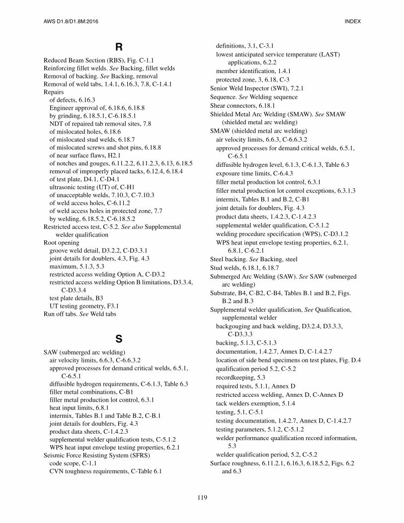
AWS D1.8/D1.8M:2016 INDEX
119
RReduced Beam Section (RBS), Fig. C-1.1Reinforcing fillet welds. See Backing, fillet weldsRemoval of backing. See Backing, removalRemoval of weld tabs, 1.4.1, 6.16.3, 7.8, C-1.4.1Repairs
of defects, 6.16.3Engineer approval of, 6.18.6, 6.18.8by grinding, 6.18.5.1, C-6.18.5.1NDT of repaired tab removal sites, 7.8of mislocated holes, 6.18.6of mislocated stud welds, 6.18.7of mislocated screws and shot pins, 6.18.8of near surface flaws, H2.1of notches and gouges, 6.11.2.2, 6.11.2.3, 6.13, 6.18.5removal of improperly placed tacks, 6.12.4, 6.18.4of test plate, D4.1, C-D4.1ultrasonic testing (UT) of, C-H1of unacceptable welds, 7.10.3, C-7.10.3of weld access holes, C-6.11.2of weld access holes in protected zone, 7.7by welding, 6.18.5.2, C-6.18.5.2
Restricted access test, C-5.2. See also Supplemental welder qualification
Root openinggroove weld detail, D3.2.2, C-D3.3.1joint details for doublers, 4.3, Fig. 4.3maximum, 5.1.3, 5.3restricted access welding Option A, C-D3.2restricted access welding Option B limitations, D3.3.4,
C-D3.3.4test plate details, B3UT testing geometry, F3.1
Run off tabs. See Weld tabs
SSAW (submerged arc welding)
air velocity limits, 6.6.3, C-6.6.3.2approved processes for demand critical welds, 6.5.1,
C-6.5.1diffusible hydrogen requirements, C-6.1.3, Table 6.3filler metal combinations, C-B1filler metal production lot control, 6.3.1heat input limits, 6.8.1intermix, Tables B.1 and Table B.2, C-B.1joint details for doublers, Fig. 4.3product data sheets, C-1.4.2.3supplemental welder qualification tests, C-5.1.2WPS heat input envelope testing properties, 6.2.1
Seismic Force Resisting System (SFRS)code scope, C-1.1CVN toughness requirements, C-Table 6.1
definitions, 3.1, C-3.1lowest anticipated service temperature (LAST)
applications, 6.2.2member identification, 1.4.1protected zone, 3, 6.18, C-3
Senior Weld Inspector (SWI), 7.2.1Sequence. See Welding sequenceShear connectors, 6.18.1Shielded Metal Arc Welding (SMAW). See SMAW
(shielded metal arc welding)SMAW (shielded metal arc welding)
air velocity limits, 6.6.3, C-6.6.3.2approved processes for demand critical welds, 6.5.1,
C-6.5.1diffusible hydrogen level, 6.1.3, C-6.1.3, Table 6.3exposure time limits, C-6.4.3filler metal production lot control, 6.3.1filler metal production lot control exceptions, 6.3.1.3intermix, Tables B.1 and B.2, C-B1joint details for doublers, Fig. 4.3product data sheets, 1.4.2.3, C-1.4.2.3supplemental welder qualification, C-5.1.2welding procedure specification (WPS), C-D3.1.2WPS heat input envelope testing properties, 6.2.1,
6.8.1, C-6.2.1Steel backing. See Backing, steelStud welds, 6.18.1, 6.18.7Submerged Arc Welding (SAW). See SAW (submerged
arc welding)Substrate, B4, C-B2, C-B4, Tables B.1 and B.2, Figs.
B.2 and B.3Supplemental welder qualification, See Qualification,
supplemental welderbackgouging and back welding, D3.2.4, D3.3.3,
C-D3.3.3backing, 5.1.3, C-5.1.3documentation, 1.4.2.7, Annex D, C-1.4.2.7location of side bend specimens on test plates, Fig. D.4qualification period 5.2, C-5.2recordkeeping, 5.3required tests, 5.1.1, Annex Drestricted access welding, Annex D, C-Annex Dtack welders exemption, 5.1.4testing, 5.1, C-5.1testing documentation, 1.4.2.7, Annex D, C-1.4.2.7testing parameters, 5.1.2, C-5.1.2welder performance qualification record information,
5.3welder qualification period, 5.2, C-5.2
Surface roughness, 6.11.2.1, 6.16.3, 6.18.5.2, Figs. 6.2 and 6.3
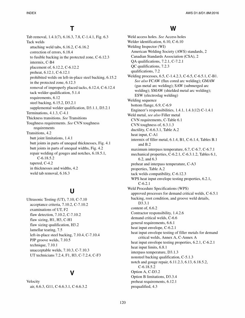
INDEX AWS D1.8/D1.8M:2016
120
TTab removal, 1.4.1(7), 6.16.3, 7.8, C-1.4.1, Fig. 6.3Tack welds
attaching weld tabs, 6.16.2, C-6.16.2correction of errors, 6.18.4to fusible backing in the protected zone, C-6.12.3intermix, C-B4placement of, 6.12.2, C-6.12.2preheat, 6.12.1, C-6.12.1prohibited welds on left-in-place steel backing, 6.15.2in the protected zone, 6.12.3removal of improperly placed tacks, 6.12.4, C-6.12.4tack welder qualification, 5.1.4requirements, 6.12steel backing, 6.15.2, D3.2.1supplemental welder qualification, D3.1.1, D3.2.1
Terminations, 4.1.3, C-4.1Thickness transitions. See TransitionsToughness requirements. See CVN toughness
requirementsTransitions, 4.2
butt joint limitations, 1.4.1butt joints in parts of unequal thicknesses, Fig. 4.1butt joints in parts of unequal widths, Fig. 4.2repair welding of gouges and notches, 6.18.5.1,
C-6.18.5.2tapered, C-4.2in thicknesses and widths, 4.2weld tab removal, 6.16.3
UUltrasonic Testing (UT), 7.10, C-7.10
acceptance criteria, 7.10.2, C-7.10.2examinations of UT, F2flaw detection, 7.10.2, C-7.10.2flaw sizing, H1, H3, C-H1flaw sizing qualification, H3.2lamellar tearing, 7.5left-in-place steel backing, 7.10.4, C-7.10.4PJP groove welds, 7.10.5technique, 7.10.1unacceptable welds, 7.10.3, C-7.10.3UT technicians 7.2.4, F1, H3, C-7.2.4, C-F3
VVelocity
air, 6.6.3, G11, C-6.6.3.1, C-6.6.3.2
WWeld access holes. See Access holesWelder identification, 6.10, C-6.10Welding Inspector (WI)
American Welding Society (AWS) standards, 2Canadian Standards Association (CSA), 2QA qualifications, 7.2.1, C-7.2.1QC qualifications, 7.2.3qualifications, 7.2
Welding processes, 6.5, C-1.4.2.3, C-6.5, C-6.5.1, C-B1. See also FCAW (flux cored arc welding); GMAW (gas metal arc welding); SAW (submerged arc welding); SMAW (shielded metal arc welding); ESW (electroslag welding)
Welding sequencebottom flange, 6.9, C-6.9Engineer’s responsibilities, 1.4.1, 1.4.1(12) C-1.4.1
Weld metal, see also Filler metalCVN requirements, C-Table 6.1CVN toughness of, 6.3.1.3ductility, C-6.6.3.1, Table A.2heat input, C-A1intermix of filler metal, 6.1.4, B1, C-6.1.4, Tables B.1
and B.2maximum interpass temperature, 6.7, C-6.7, C-6.7.1mechanical properties, C-6.2.1, C-6.3.1.2, Tables 6.1,
6.2, and 6.3preheat and interpass temperature, C-A3properties, Table A.2tack welds compatibility, C-6.12.3WPS heat input envelope testing properties, 6.2.1,
C-6.2.1Weld Procedure Specifications (WPS)
approved processes for demand critical welds, C-6.5.1backing, root condition, and groove weld details,
D3.3.1content of, 6.6.2Contractor responsibility, 1.4.2.6demand critical welds, C-6.6general requirements, 6.6.1heat input envelope, C-6.2.1heat input envelope testing of filler metals for demand
critical welds, Annex A, C-Annex Aheat input envelope testing properties, 6.2.1, C-6.2.1heat input limits, 6.8.1interpass temperature, D3.1.3nonsteel backing qualification, C-5.1.3notch and gouge repair, 6.11.2.3, 6.13, 6.18.5.2,
C-6.18.5.2Option A, C-D3.2Option B limitations, D3.3.4preheat requirements, 6.12.1prequalified, 4.3
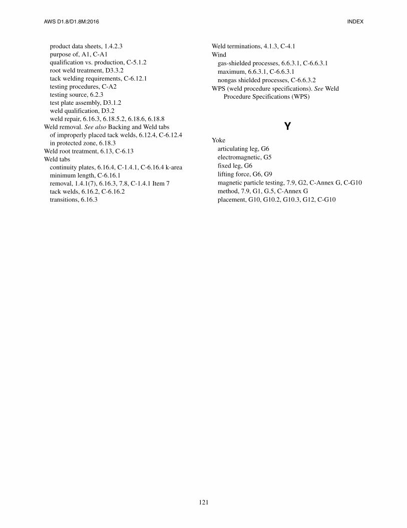
AWS D1.8/D1.8M:2016 INDEX
121
product data sheets, 1.4.2.3purpose of, A1, C-A1qualification vs. production, C-5.1.2root weld treatment, D3.3.2tack welding requirements, C-6.12.1testing procedures, C-A2testing source, 6.2.3test plate assembly, D3.1.2weld qualification, D3.2weld repair, 6.16.3, 6.18.5.2, 6.18.6, 6.18.8
Weld removal. See also Backing and Weld tabsof improperly placed tack welds, 6.12.4, C-6.12.4in protected zone, 6.18.3
Weld root treatment, 6.13, C-6.13Weld tabs
continuity plates, 6.16.4, C-1.4.1, C-6.16.4 k-areaminimum length, C-6.16.1removal, 1.4.1(7), 6.16.3, 7.8, C-1.4.1 Item 7tack welds, 6.16.2, C-6.16.2transitions, 6.16.3
Weld terminations, 4.1.3, C-4.1Wind
gas-shielded processes, 6.6.3.1, C-6.6.3.1maximum, 6.6.3.1, C-6.6.3.1nongas shielded processes, C-6.6.3.2
WPS (weld procedure specifications). See Weld Procedure Specifications (WPS)
YYoke
articulating leg, G6electromagnetic, G5fixed leg, G6lifting force, G6, G9magnetic particle testing, 7.9, G2, C-Annex G, C-G10method, 7.9, G1, G.5, C-Annex Gplacement, G10, G10.2, G10.3, G12, C-G10

This page is intentionally blank.
AWS D1.8/D1.8M:2016
122
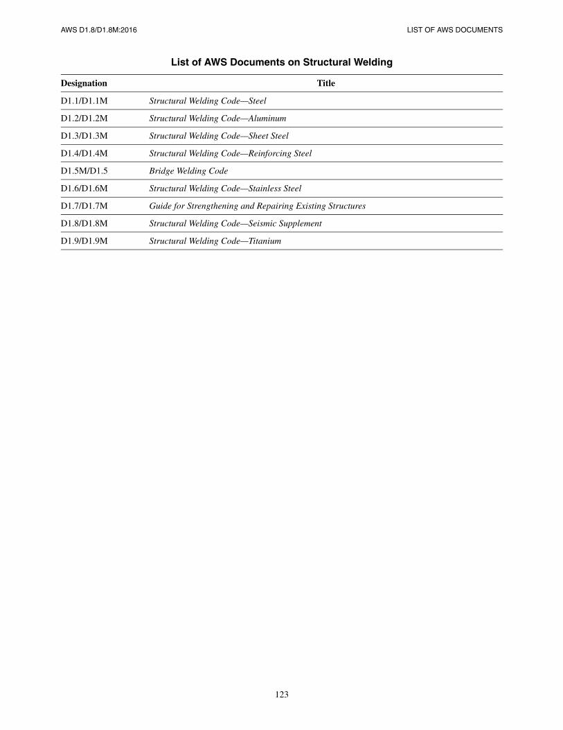
AWS D1.8/D1.8M:2016 LIST OF AWS DOCUMENTS
123
List of AWS Documents on Structural Welding
Designation Title
D1.1/D1.1M Structural Welding Code—Steel
D1.2/D1.2M Structural Welding Code—Aluminum
D1.3/D1.3M Structural Welding Code—Sheet Steel
D1.4/D1.4M Structural Welding Code—Reinforcing Steel
D1.5M/D1.5 Bridge Welding Code
D1.6/D1.6M Structural Welding Code—Stainless Steel
D1.7/D1.7M Guide for Strengthening and Repairing Existing Structures
D1.8/D1.8M Structural Welding Code—Seismic Supplement
D1.9/D1.9M Structural Welding Code—Titanium
This page is intentionally blank.
AWS D1.8/D1.8M:2016
124