Embed Size (px)
Citation preview
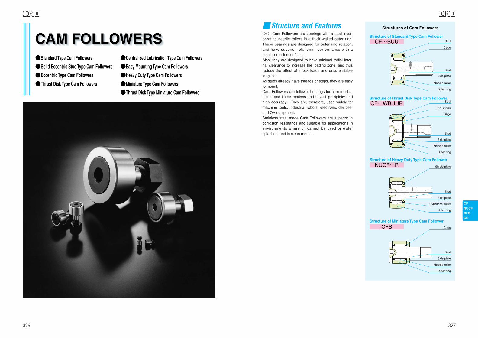
Cam Followers are bearings with a stud incor-porating needle rollers in a thick walled outer ring.These bearings are designed for outer ring rotation,and have superior rotational performance with asmall coefficient of friction. Also, they are designed to have minimal radial inter-nal clearance to increase the loading zone, and thusreduce the effect of shock loads and ensure stablelong life.As studs already have threads or steps, they are easyto mount.Cam Followers are follower bearings for cam mecha-nisms and linear motions and have high rigidity andhigh accuracy. They are, therefore, used widely formachine tools, industrial robots, electronic devices,and OA equipment.Stainless steel made Cam Followers are superior incorrosion resistance and suitable for applications inenvironments where oil cannot be used or watersplashed, and in clean rooms.
Strucfures of Cam Followers
Seal
Cage
Stud
Side plate
Needle roller
Outer ring
Seal
Thrust disk
Cage
Stud
Side plate
Needle roller
Outer ring
Shield plate
Cage
Stud
Side plate
Needle roller
Outer ring
Stud
Side plate
Cylindrical roller
Outer ring
Structure of Standard Type Cam Follower
Structure of Thrust Disk Type Cam Follower
Structure of Heavy Duty Type Cam Follower
Structure of Miniature Type Cam Follower
■Structure and Features
327
●Standard Type Cam Followers
●Solid Eccentric Stud Type Cam Followers
●Eccentric Type Cam Followers
●Thrust Disk Type Cam Followers
●Centralized Lubrication Type Cam Followers
●Easy Mounting Type Cam Followers
●Heavy Duty Type Cam Followers
●Miniature Type Cam Followers
●Thrust Disk Type Miniature Cam Followers
326
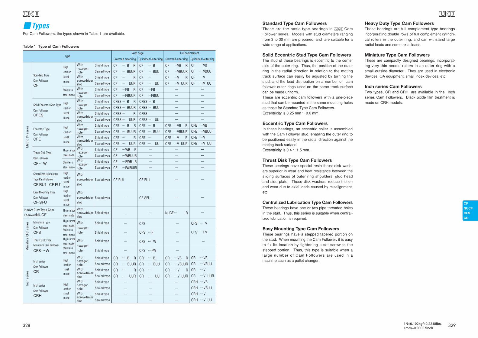
Standard Type Cam FollowersThese are the basic type bearings in CamFollower series. Models with stud diameters rangingfrom 3 to 30 mm are prepared, and are suitable for awide range of applications.
Solid Eccentric Stud Type Cam FollowersThe stud of these bearings is eccentric to the centeraxis of the outer ring. Thus, the position of the outerring in the radial direction in relation to the matingtrack surface can easily be adjusted by turning thestud, and the load distribution on a number of camfollower outer rings used on the same track surfacecan be made uniform. These are eccentric cam followers with a one-piecestud that can be mounted in the same mounting holesas those for Standard Type Cam Followers.Eccentricity is 0.25 mm~0.6 mm.
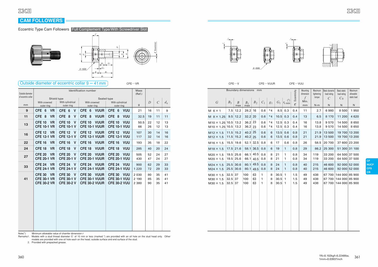
Eccentric Type Cam FollowersIn these bearings, an eccentric collar is assembledwith the Cam Follower stud, enabling the outer ring tobe positioned easily in the radial direction against themating track surface.Eccentricity is 0.4~1.5 mm.
Thrust Disk Type Cam FollowersThese bearings have special resin thrust disk wash-ers superior in wear and heat resistance between thesliding surfaces of outer ring shoulders, stud headand side plate. These disk washers reduce frictionand wear due to axial loads caused by misalignment,etc.
Centralized Lubrication Type Cam FollowersThese bearings have one or two pipe-threaded holesin the stud. Thus, this series is suitable when central-ized lubrication is required.
Easy Mounting Type Cam FollowersThese bearings have a stepped tapered portion onthe stud. When mounting the Cam Follower, it is easyto fix its location by tightening a set screw to thestepped portion. Thus, this type is suitable when alarge number of Cam Followers are used in amachine such as a pallet changer.
Heavy Duty Type Cam FollowersThese bearings are full complement type bearingsincorporating double rows of full complement cylindri-cal rollers in the outer ring, and can withstand largeradial loads and some axial loads.
Miniature Type Cam FollowersThese are compactly designed bearings, incorporat-ing very thin needle rollers in an outer ring with asmall outside diameter. They are used in electronicdevices, OA equipment, small index devices, etc.
Inch series Cam FollowersTwo types, CR and CRH, are available in the Inchseries Cam Followers. Black oxide film treatment ismade on CRH models.
329
■TypesFor Cam Followers, the types shown in Table 1 are available.
Table 1 Type of Cam Followers
Type
Met
ricCF
serie
s
Heavy Duty Type CamFollowerNUCF
Min
iatu
reCF
Sse
ries
Inch
serie
s
Standard Type
Cam FollowerCF
High carbonsteel made
Solid Eccentric Stud Type
Cam FollowerCFES
Eccentric Type
Cam FollowerCFE
Stainlesssteel made
High carbonsteel made
High carbonsteel made
Thrust Disk Type
Cam Follower
CF…W
Centralized Lubrication
Type Cam Follower
CF-RU1,CF-FU1
Easy Mounting Type
Cam FollowerCF-SFU
High carbonsteel made
High carbonsteel made
High carbonsteel madeStainlesssteel madeHigh carbonsteel madeStainlesssteel made
Stainlesssteel made
High carbonsteel madeHigh carbonsteel made
High carbonsteel made
High carbonsteel made
Miniature Type
Cam FollowerCFS
Thrust Disk TypeMiniature Cam Follower
CFS…W
Inch series
Cam FollowerCR
Inch series
Cam FollowerCRH
With hexagon holeWithscrewdriverslotWithhexagonholeWithhexagonholeWithscrewdriverslotWithhexagonholeWithscrewdriverslotWithhexagonholeWithhexagonhole
Withscrewdriverslot
Withscrewdriverslot
Withhexagonhole
Withhexagonhole
WithhexagonholeWithscrewdriverslotWithhexagonholeWithscrewdriverslot
Withscrewdriverslot
CF … B R
CF … BUUR
CF … R
CF … UUR
CF …FB R
CF …FBUUR
CFES… B R
CFES… BUUR
CFES… R
CFES… UUR
CFE … B R
CFE … BUUR
CFE … R
CFE … UUR
CF …WB R
CF …WBUUR
CF …FWB R
CF …FWBUUR
CF-RU1
─
─
─
─
─
─
CR … B R
CR … BUUR
CR … R
CR … UUR
─
─
─
─
CF … B
CF … BUU
CF …
CF … UU
CF …FB
CF …FBUU
CFES… B
CFES… BUU
CFES
CFES… UU
CFE … B
CFE … BUU
CFE …
CFE … UU
ー
ー
ー
ー
CF-FU1
CF-SFU
ー
CFS
CFS …F
CFS … W
CFS …FW
CR … B
CR … BUU
CR …
CR … UU
ー
ー
ー
ー
CF …VB R
CF …VBUUR
CF …V R
CF …V UUR
ー
ー
ー
ー
ー
ー
CFE …VB R
CFE …VBUUR
CFE …V R
CFE …V UUR
ー
ー
ー
ー
ー
ー
NUCF… R
─
─
─
─
CR …VB R
CR …VBUUR
CR …V R
CR …V UUR
ー
ー
ー
ー
CF …VB
CF …VBUU
CF …V
CF …V UU
ー
ー
ー
ー
ー
ー
CFE …VB
CFE …VBUU
CFE …V
CFE …V UU
ー
ー
ー
ー
ー
ー
ー
CFS … V
CFS …FV
─
─
CR …VB
CR …VBUU
CR …V
CR …V UUR
CRH …VB
CRH …VBUU
CRH …V
CRH …V UU
Shield type
Sealed type
Shield type
Sealed type
Shield type
Sealed type
Shield type
Sealed type
Shield type
Sealed type
Shield type
Sealed type
Shield type
Sealed type
Shield type
Sealed type
Shield type
Sealed type
Sealed type
Sealed type
Shield type
Shield type
Shield type
Shield type
Shield type
Shield type
Sealed type
Shield type
Sealed type
Shield type
Sealed type
Shield type
Sealed type
With cage Full complement
Crowned outer ring Cylindrical outer ring Crowned outer ring Cylindrical outer ring
328 1N=0.102kgf=0.2248lbs.1mm=0.03937inch
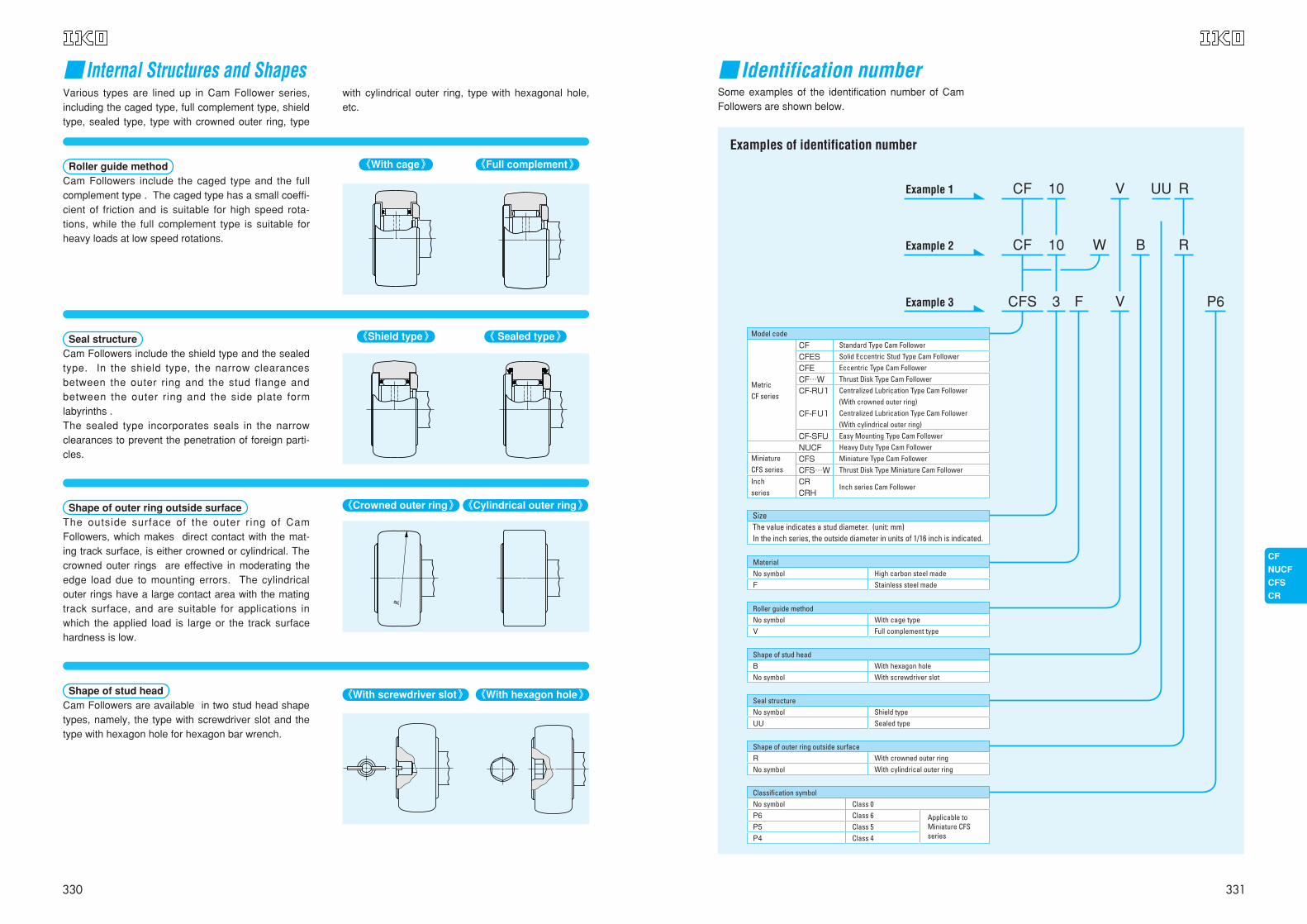
■ Identification numberSome examples of the identification number of CamFollowers are shown below.
10CF RV
V
UU
10CF RBW
3CFS P6F
CF CFES CFE CF…W CF-RU1 CF-FU1 CF-SFU NUCF CFS CFS…W CR CRH
Standard Type Cam FollowerSolid Eccentric Stud Type Cam FollowerEccentric Type Cam FollowerThrust Disk Type Cam FollowerCentralized Lubrication Type Cam Follower(With crowned outer ring)Centralized Lubrication Type Cam Follower (With cylindrical outer ring)Easy Mounting Type Cam FollowerHeavy Duty Type Cam FollowerMiniature Type Cam FollowerThrust Disk Type Miniature Cam Follower
Inch series Cam Follower
With cage typeFull complement type
Roller guide methodNo symbol V
High carbon steel madeStainless steel made
MaterialNo symbolF
With hexagon holeWith screwdriver slot
Shape of stud headB No symbol
Shield typeSealed type
Seal structureNo symbol UU
With crowned outer ringWith cylindrical outer ring
Shape of outer ring outside surfaceR No symbol
Classification symbolNo symbol P6
P5
P4
Class 0Class 6Class 5Class 4
Applicable to Miniature CFS series
Example 1
Example 2
Example 3
Metric CF series
Inch series
Miniature CFS series
Model code
SizeThe value indicates a stud diameter. (unit: mm)In the inch series, the outside diameter in units of 1/16 inch is indicated.
Examples of identification number
331
■ Internal Structures and Shapes
《Full complement》《With cage》
《Shield type》 《 Sealed type》
《Crowned outer ring》 《Cylindrical outer ring》
《With screwdriver slot》 《With hexagon hole》
Roller guide methodCam Followers include the caged type and the fullcomplement type . The caged type has a small coeffi-cient of friction and is suitable for high speed rota-tions, while the full complement type is suitable forheavy loads at low speed rotations.
Seal structureCam Followers include the shield type and the sealedtype. In the shield type, the narrow clearancesbetween the outer ring and the stud flange andbetween the outer ring and the side plate formlabyrinths .The sealed type incorporates seals in the narrowclearances to prevent the penetration of foreign parti-cles.
Shape of outer ring outside surfaceThe outside surface of the outer ring of CamFollowers, which makes direct contact with the mat-ing track surface, is either crowned or cylindrical. Thecrowned outer rings are effective in moderating theedge load due to mounting errors. The cylindricalouter rings have a large contact area with the matingtrack surface, and are suitable for applications inwhich the applied load is large or the track surfacehardness is low.
Shape of stud headCam Followers are available in two stud head shapetypes, namely, the type with screwdriver slot and thetype with hexagon hole for hexagon bar wrench.
Various types are lined up in Cam Follower series,including the caged type, full complement type, shieldtype, sealed type, type with crowned outer ring, type
with cylindrical outer ring, type with hexagonal hole,etc.
R
330
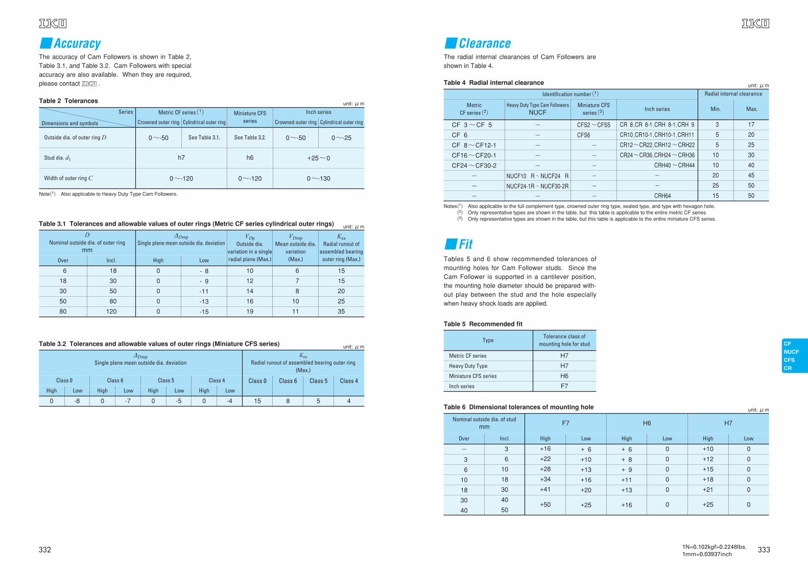
■FitTables 5 and 6 show recommended tolerances ofmounting holes for Cam Follower studs. Since theCam Follower is supported in a cantilever position,the mounting hole diameter should be prepared with-out play between the stud and the hole especiallywhen heavy shock loads are applied.
■ClearanceThe radial internal clearances of Cam Followers areshown in Table 4.
Notes(1) Also applicable to the full complement type, crowned outer ring type, sealed type, and type with hexagon hole.Notes(2) Only representative types are shown in the table, but this table is applicable to the entire metric CF series.Notes(3) Only representative types are shown in the table, but this table is applicable to the entire miniature CFS series.
Table 4 Radial internal clearance
Identification number(1)
CF 3 ~CF 5
CF 6
CF 8~CF12-1
CF16~CF20-1
CF24~CF30-2
-
-
-
-
-
-
-
-
NUCF10 R~NUCF24 R
NUCF24-1R~NUCF30-2R
-
CFS2 ~CFS5
CFS6
-
-
-
-
-
-
CR 8,CR 8-1,CRH 8-1,CRH 9
CR10,CR10-1,CRH10-1,CRH11
CR12~CR22,CRH12 ~CRH22
CR24~CR36,CRH24 ~CRH36
CRH40 ~CRH44
-
-
CRH64
3
5
5
10
10
20
25
15
17
20
25
30
40
45
50
50
Radial internal clearance
Min. Max.Metric
CF series(2)Heavy Duty Type Cam Followers
NUCFMiniature CFS
series(3)Inch series
unit: μm
Table 5 Recommended fit
Type
Metric CF series
Heavy Duty Type
Miniature CFS series
Inch series
H7
H7
H6
F7
Tolerance class ofmounting hole for stud
Table 6 Dimensional tolerances of mounting hole
Nominal outside dia. of studmm F7 H6 H7
Over Incl. High Low High Low High Low
-
3
6
10
18
30
40
3
6
10
18
30
40
50
+16
+22
+28
+34
+41
+50
+ 6
+10
+13
+16
+20
+25
+ 6
+ 8
+ 9
+11
+13
+16
0
0
0
0
0
0
+10
+12
+15
+18
+21
+25
0
0
0
0
0
0
unit: μm
3331N=0.102kgf=0.2248lbs.1mm=0.03937inch
■AccuracyThe accuracy of Cam Followers is shown in Table 2,Table 3.1, and Table 3.2. Cam Followers with specialaccuracy are also available. When they are required,please contact .
Note(1) Also applicable to Heavy Duty Type Cam Followers.
Table 2 Tolerances
Series
Dimensions and symbols
Outside dia. of outer ring D
Stud dia. d1
Width of outer ring C
0~-50
h7 h6 +25~0
0~-120 0~-120 0~-130
0~-50 0~-25See Table 3.1. See Table 3.2.
Metric CF series(1)
Crowned outer ring Cylindrical outer ring
Inch series
Crowned outer ring Cylindrical outer ring
Miniature CFSseries
unit: μm
Table 3.1 Tolerances and allowable values of outer rings (Metric CF series cylindrical outer rings)
DNominal outside dia. of outer ring
mm
Over Incl. High Low
∆DmpSingle plane mean outside dia. deviation
6
18
30
50
80
18
30
50
80
120
0
0
0
0
0
- 8
- 9
-11
-13
-15
10
12
14
16
19
6
7
8
10
11
15
15
20
25
35
VDpOutside dia.
variation in a single radial plane (Max.)
VDmpMean outside dia.
variation (Max.)
KeaRadial runout of
assembled bearing outer ring (Max.)
unit: μm
Table 3.2 Tolerances and allowable values of outer rings (Miniature CFS series)
∆DmpSingle plane mean outside dia. deviation
Class 0
High Low Low Low LowHigh High High
Class 6 Class 5 Class 4 Class 0 Class 6 Class 5 Class 4
0 -8 0 -7 0 -5 0 -4 15 8 5 4
Kea
Radial runout of assembled bearing outer ring(Max.)
unit: μm
332
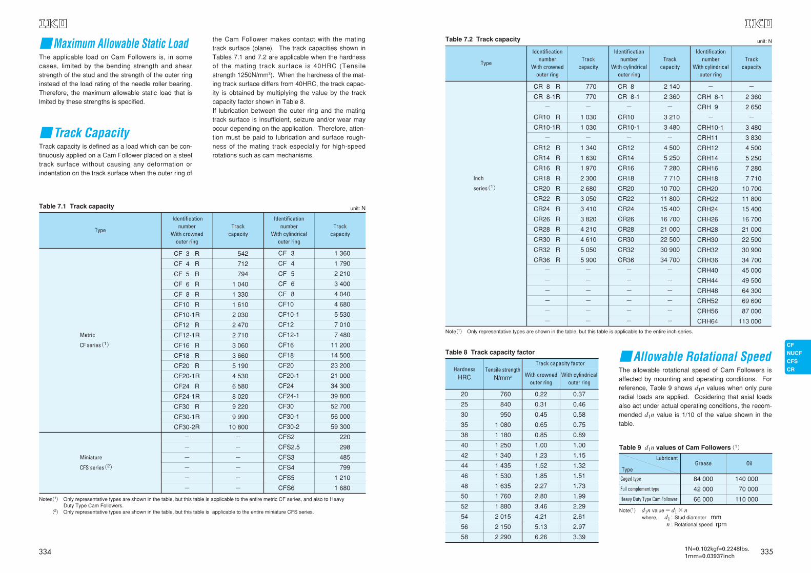
■Allowable Rotational SpeedThe allowable rotational speed of Cam Followers isaffected by mounting and operating conditions. Forreference, Table 9 shows d1n values when only pureradial loads are applied. Cosidering that axial loadsalso act under actual operating conditions, the recom-mended d1n value is 1/10 of the value shown in thetable.
Note(1) Only representative types are shown in the table, but this table is applicable to the entire inch series.
Table 7.2 Track capacity
Type
Inch
series(1)
Identificationnumber
With crownedouter ring
CR 8 R
CR 8-1R
-
CR10 R
CR10-1R
-
CR12 R
CR14 R
CR16 R
CR18 R
CR20 R
CR22 R
CR24 R
CR26 R
CR28 R
CR30 R
CR32 R
CR36 R
-
-
-
-
-
-
770
770
-
1 030
1 030
-
1 340
1 630
1 970
2 300
2 680
3 050
3 410
3 820
4 210
4 610
5 050
5 900
-
-
-
-
-
-
CR 8
CR 8-1
-
CR10
CR10-1
-
CR12
CR14
CR16
CR18
CR20
CR22
CR24
CR26
CR28
CR30
CR32
CR36
-
-
-
-
-
-
-
CRH 8-1
CRH 9
-
CRH10-1
CRH11
CRH12
CRH14
CRH16
CRH18
CRH20
CRH22
CRH24
CRH26
CRH28
CRH30
CRH32
CRH36
CRH40
CRH44
CRH48
CRH52
CRH56
CRH64
2 140
2 360
-
3 210
3 480
-
4 500
5 250
7 280
7 710
10 700
11 800
15 400
16 700
21 000
22 500
30 900
34 700
-
-
-
-
-
-
-
2 360
2 650
-
3 480
3 830
4 500
5 250
7 280
7 710
10 700
11 800
15 400
16 700
21 000
22 500
30 900
34 700
45 000
49 500
64 300
69 600
87 000
113 000
Track capacity
Identificationnumber
With cylindricalouter ring
Identificationnumber
With cylindricalouter ring
Track capacity
Track capacity
unit: N
Table 8 Track capacity factor
HardnessHRC
Tensile strengthN/mm2
Track capacity factor
With cylindrical outer ring
With crowned outer ring
20
25
30
35
38
40
42
44
46
48
50
52
54
56
58
760
840
950
1 080
1 180
1 250
1 340
1 435
1 530
1 635
1 760
1 880
2 015
2 150
2 290
0.22
0.31
0.45
0.65
0.85
1.00
1.23
1.52
1.85
2.27
2.80
3.46
4.21
5.13
6.26
0.37
0.46
0.58
0.75
0.89
1.00
1.15
1.32
1.51
1.73
1.99
2.29
2.61
2.97
3.39
Table 9 d1n values of Cam Followers(1)
Lubricant
Type
Caged type
Full complement type
Heavy Duty Type Cam Follower
84 000
42 000
66 000
140 000
70 000
110 000
Grease Oil
Note(1) d1n value=d1×nwhere, d1 : Stud diameter mm
n : Rotational speed rpm
3351N=0.102kgf=0.2248lbs.1mm=0.03937inch
■Maximum Allowable Static LoadThe applicable load on Cam Followers is, in somecases, limited by the bending strength and shearstrength of the stud and the strength of the outer ringinstead of the load rating of the needle roller bearing.Therefore, the maximum allowable static load that islmited by these strengths is specified.
■Track CapacityTrack capacity is defined as a load which can be con-tinuously applied on a Cam Follower placed on a steeltrack surface without causing any deformation orindentation on the track surface when the outer ring of
Notes(1) Only representative types are shown in the table, but this table is applicable to the entire metric CF series, and also to Heavy Duty Type Cam Followers.
Notes(2) Only representative types are shown in the table, but this table is applicable to the entire miniature CFS series.
Table 7.1 Track capacity
Type
Metric
CF series(1)
Miniature
CFS series(2)
Identification number
With crowned outer ring
CF 3 R
CF 4 R
CF 5 R
CF 6 R
CF 8 R
CF10 R
CF10-1R
CF12 R
CF12-1R
CF16 R
CF18 R
CF20 R
CF20-1R
CF24 R
CF24-1R
CF30 R
CF30-1R
CF30-2R
-
-
-
-
-
-
542
712
794
1 040
1 330
1 610
2 030
2 470
2 710
3 060
3 660
5 190
4 530
6 580
8 020
9 220
9 990
10 800
-
-
-
-
-
-
CF 3
CF 4
CF 5
CF 6
CF 8
CF10
CF10-1
CF12
CF12-1
CF16
CF18
CF20
CF20-1
CF24
CF24-1
CF30
CF30-1
CF30-2
CFS2
CFS2.5
CFS3
CFS4
CFS5
CFS6
1 360
1 790
2 210
3 400
4 040
4 680
5 530
7 010
7 480
11 200
14 500
23 200
21 000
34 300
39 800
52 700
56 000
59 300
220
298
485
799
1 210
1 680
Track capacity
Identification number
With cylindrical outer ring
Track capacity
unit: N
the Cam Follower makes contact with the matingtrack surface (plane). The track capacities shown inTables 7.1 and 7.2 are applicable when the hardnessof the mating track surface is 40HRC (Tensilestrength 1250N/mm2). When the hardness of the mat-ing track surface differs from 40HRC, the track capac-ity is obtained by multiplying the value by the trackcapacity factor shown in Table 8.If lubrication between the outer ring and the matingtrack surface is insufficient, seizure and/or wear mayoccur depending on the application. Therefore, atten-tion must be paid to lubrication and surface rough-ness of the mating track especially for high-speedrotations such as cam mechanisms.
334
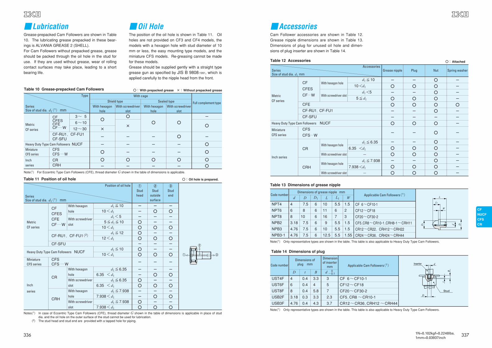
■AccessoriesCam Follower accessories are shown in Table 12.Grease nipple dimensions are shown in Table 13.Dimensions of plug for unused oil hole and dimen-sions of plug inserter are shown in Table 14.
Table 12 Accessories
AccessoriesSeriesSize of stud dia. d1 mm
Metric CF series
Miniature CFS series
Inch series
Heavy Duty Type Cam Followers NUCF
CF
CFES
CF…W
CFE
CF-RU1,CF-FU1
CF-SFU
CFS
CFS…W
CR
CRH
With hexagon hole
With screwdriver slot
With hexagon hole
With screwdriver slot
With hexagon hole
With screwdriver slot
-
〇
-
〇
〇
-
-
〇
-
-
〇
〇
-
〇
〇
-
〇
-
〇
〇
-
-
〇
-
-
〇
〇
-
〇
〇
〇
〇
〇
〇
〇
〇
-
〇
〇
〇
〇
〇
〇
〇
〇
-
-
-
-
〇
-
-
-
-
-
-
-
-
-
-
d1≦10
10<d1
d1<5
5≦d1
d1≦6.35
6.350<d1
-
d1≦7.938
7.938<d1
-
Grease nipple Plug Nut Spring washer
〇:Attached
Table 13 Dimensions of grease nipple
Code numberDimensions of grease nipple mm
Applicable Cam Followers(1)
NPT4
NPT6
NPT8
NPB2
NPB3
NPB3-1
4
6
8
3.18
4.76
4.76
d D D1 L L1 W
7.5
8
10
7.5
7.5
7.5
6
6
6
6
6
6
10
11
16
9
10
12.5
5.5
6
7
5.5
5.5
5.5
1.5
2
3
1.5
1.5
1.55
CF 6~CF10-1
CF12~CF18
CF20~CF30-2
CF5,CR8~CR10-1,CRH8-1~CRH11
CR12~CR22,CRH12~CRH22
CR24~CR36,CRH24~CRH44
Note(1) Only representative types are shown in the table. This table is also applicable to Heavy Duty Type Cam Followers.
Table 14 Dimensions of plug
Code numberDimensions of
plug mm
Dimensionof inserter
mm Applicable Cam Followers(1)
UST4F
UST6F
UST8F
USB2F
USB3F
4
6
8
3.18
4.76
D t B d 0-0.1
0.4
0.4
0.4
0.3
0.4
3.3
4
5.8
3.3
4.3
3
5
7
2.3
3.7
CF 6~CF10-1
CF12~CF18
CF20~CF30-2
CF5,CR8 ~CR10-1
CR12~CR36,CRH12 ~CRH44
Note(1) Only representative types are shown in the table. This table is also applicable to Heavy Duty Type Cam Followers.
3371N=0.102kgf=0.2248lbs.1mm=0.03937inch
■LubricationGrease-prepacked Cam Followers are shown in Table10. The lubricating grease prepacked in these bear-ings is ALVANIA GREASE 2 (SHELL).For Cam Followers without prepacked grease, greaseshould be packed through the oil hole in the stud foruse. If they are used without grease, wear of rollingcontact surfaces may take place, leading to a shortbearing life.
■Oil HoleThe position of the oil hole is shown in Table 11. Oilholes are not provided on CF3 and CF4 models, themodels with a hexagon hole with stud diameter of 10mm or less, the easy mounting type models, and theminiature CFS models. Re-greasing cannot be madefor these models.Grease should be supplied gently with a straight typegrease gun as specified by JIS B 9808:1991, which isapplied carefully to the nipple head from the front.
Type
SeriesSize of stud dia. d1(1)mm
Metric CF series
Heavy Duty Type Cam Followers NUCFMiniature CFS series
Inch series
CFS CFS …W
CRCRH
CF CFESCFE CF…W
CF-RU1,CF-FU1CF-SFU
3~ 5
6~10
12~30
Table 10 Grease-prepacked Cam Followers
With cage
Shield type Sealed type Full complement type
〇
×
-
-
〇
〇
-
〇
×
-
-
-
〇
-
-
-
-
〇
-
〇
-
-
〇
-
-
〇
-
〇
〇
〇
〇
With hexagon hole
With screwdriver slot
With hexagon hole
With screwdriver slot
〇:With prepacked grease ×:Without prepacked grease
Note(1) For Eccentric Type Cam Followers (CFE), thread diameter G shown in the table of dimensions is applicable.
〇〇
Table 11 Position of oil hole
Position of oil hole
SeriesSize of stud dia. d1(1)mm
①Stud head
②Stud
outsidesurface
③Stud end
Metric CF series
CF CFESCFE CF…W
CF-RU1,CF-FU1(2)
Heavy Duty Type Cam Followers NUCF
Miniature CFS series
Inch
series
CFS CFS …W
CF-SFU
d1≦1010<d1
d1<55≦d1≦10
10<d1
d1≦1212<d1
d1≦1010<d1
With hexagon
hole
With screwdriver
slot
---〇〇〇〇-〇〇
-
--〇〇--〇〇
-〇--〇-〇--〇
-
-〇-〇-〇-〇
-〇--〇-〇--〇
-
-〇-〇-〇-〇
CR
CRH
With hexagon
hole
With screwdriver
slot
With hexagon
hole
With screwdriver
slot
d1≦6.356.35 <d1
d1≦6.356.35 <d1
d1≦7.9387.938<d1
d1≦7.9387.938<d1
Notes(1) In case of Eccentric Type Cam Followers (CFE), thread diameter G shown in the table of dimensions is applicable in place of studdia. and the oil hole on the outer surface of the stud cannot be used for lubrication.
Notes(2) The stud head and stud end are provided with a tapped hole for piping.
〇:Oil hole is prepared.
③
②
①
336
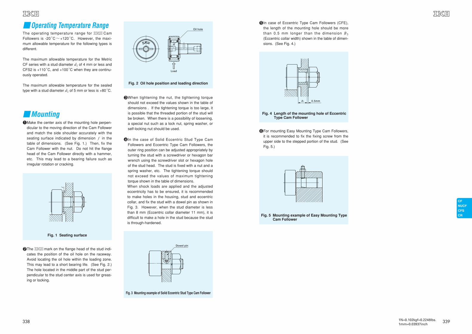
5 In case of Eccentric Type Cam Followers (CFE),the length of the mounting hole should be morethan 0.5 mm longer than the dimension B3
(Eccentric collar width) shown in the table of dimen-sions. (See Fig. 4.)
6 For mounting Easy Mounting Type Cam Followers,it is recommended to fix the fixing screw from theupper side to the stepped portion of the stud. (SeeFig. 5.)
Fig. 4 Length of the mounting hole of EccentricType Cam Follower
Fig. 5 Mounting example of Easy Mounting TypeCam Follower
339
■Operating Temperature RangeThe operating temperature range for CamFollowers is -20 C゚~+120 C゚. However, the maxi-mum allowable temperature for the following types isdifferent.
The maximum allowable temperature for the MetricCF series with a stud diameter d1 of 4 mm or less andCFS2 is +110 C゚, and +100 C゚ when they are continu-ously operated.
The maximum allowable temperature for the sealedtype with a stud diameter d1 of 5 mm or less is +80 C゚.
■Mounting1 Make the center axis of the mounting hole perpen-
dicular to the moving direction of the Cam Followerand match the side shoulder accurately with theseating surface indicated by dimension f in thetable of dimensions. (See Fig. 1.) Then, fix theCam Follower with the nut. Do not hit the flangehead of the Cam Follower directly with a hammer,etc. This may lead to a bearing failure such asirregular rotation or cracking.
2 The mark on the flange head of the stud indi-cates the position of the oil hole on the raceway.Avoid locating the oil hole within the loading zone.This may lead to a short bearing life. (See Fig. 2.)The hole located in the middle part of the stud per-pendicular to the stud center axis is used for greas-ing or locking.
3 When tightening the nut, the tightening torqueshould not exceed the values shown in the table ofdimensions . If the tightening torque is too large, itis possible that the threaded portion of the stud willbe broken. When there is a possibility of loosening,a special nut such as a lock nut, spring washer, orself-locking nut should be used.
Fig. 1 Seating surface
Fig. 2 Oil hole position and loading direction
Fig. 3 Mounting example of Solid Eccentric Stud Type Cam Follower
4 In the case of Solid Eccentric Stud Type CamFollowers and Eccentric Type Cam Followers, theouter ring position can be adjusted appropriately byturning the stud with a screwdriver or hexagon barwrench using the screwdriver slot or hexagon holeof the stud head. The stud is fixed with a nut and aspring washer, etc. The tightening torque shouldnot exceed the values of maximum tighteningtorque shown in the table of dimensions.When shock loads are applied and the adjustedeccentricity has to be ensured, it is recommendedto make holes in the housing, stud and eccentriccollar, and fix the stud with a dowel pin as shown inFig. 3. However, when the stud diameter is lessthan 8 mm (Eccentric collar diameter 11 mm), it isdifficult to make a hole in the stud because the studis through-hardened.
Load
Oil hole
Dowel pin
338 1N=0.102kgf=0.2248lbs.1mm=0.03937inch
5
6
7.5
8
1010
12121212
1313
17
19
2121
2525
323232
9
11
13
16
2020
23232323
2525
32.5
36.5
40.540.5
49.549.5
636363
─
─
─
─
──
────
66
8
8
99
1111
151515
0.5
0.5
0.5
0.6
0.60.6
0.60.60.60.6
0.60.6
0.8
0.8
0.80.8
0.80.8
111
─
─
─
─
──
────
66
6
6
88
88
888
─
─
─
─
──
────
33
3
3
44
44
444
2
2.5
3
3
44
4444
66
6
8
88
1212
171717
0.2
0.3
0.3
0.3
0.30.3
0.30.30.30.3
0.60.6
0.6
1
11
11
111
6.8
8.3
9.3
11
1313
16161616
2121
26
29
3434
4040
494949
0.34
0.78
1.6
2.7
6.57.1
13.814.713.814.7
21.921.9
58.5
86.2
119119
215215
438438438
1 500
2 070
2 520
3 660
4 2504 250
5 4305 4305 4305 430
7 9107 910
12 000
14 800
20 70020 700
30 50030 500
45 40045 40045 400
1 020
1 590
2 140
3 650
4 7404 740
6 8906 8906 8906 890
9 7909 790
18 300
25 200
34 60034 600
52 60052 600
85 10085 10085 100
384
834
1 260
1 950
4 6204 620
6 8906 8906 8906 890
9 7909 790
18 300
25 200
34 60034 600
52 00052 000
85 10085 10085 100
8
9
10
12.2max
12.2max12.2max
13.2max13.2max13.2max13.2max
15.2max15.2max
19.6max
21.6max
25.6max25.6max
30.6max30.6max
37 max37 max37 max
17
20
23
28.2max
32.2max32.2max
36.2max36.2max36.2max36.2max
40.2max40.2max
52.1max
58.1max
66.1max66.1max
80.1max80.1max
100 max100 max100 max
(1)
Boundary dimensions mm
CF…B CF…BUUR CF…BUU
G1 B2 B3 C1 g1 g2 H rs minB B1
Mountingdimension
fMin.mm
Maximumtightening
torque
N-m
Basic dynamicload rating
C
N
Basic staticload rating
C0
N
Maximumallowablestatic load
N
3411N=0.102kgf=0.2248lbs.1mm=0.03937inch
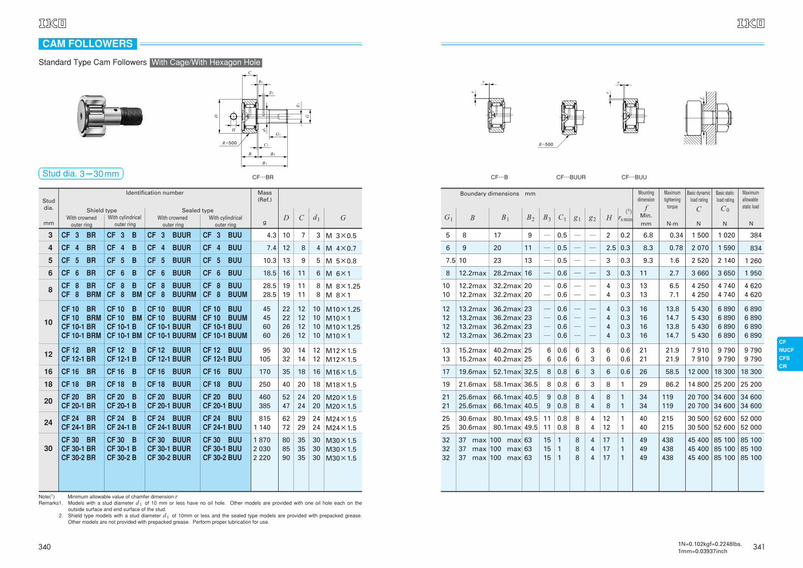
Note(1) Minimum allowable value of chamfer dimension rRemarks1. Models with a stud diameter d1 of 10 mm or less have no oil hole. Other models are provided with one oil hole each on the
outside surface and end surface of the stud.Remarks2. Shield type models with a stud diameter d1 of 10mm or less and the sealed type models are provided with prepacked grease.
Other models are not provided with prepacked grease. Perform proper lubrication for use.
Standard Type Cam Followers With Cage/With Hexagon Hole
Studdia.
mmWith crowned
outer ring
Shield typeWith cylindrical
outer ringWith crowned
outer ringWith cylindrical
outer ring
Mass(Ref.)
Identification number
g
3
4
5
6
8
CF 3 BR
CF 4 BR
CF 5 BR
CF 6 BR
CF 8 BRCF 8 BRM
CF 8 BCF 8 BM
CF 10 BRCF 10 BRMCF 10-1 BRCF 10-1 BRM
CF 12 BRCF 12-1 BR
CF 16 BR
CF 18 BR
CF 20 BRCF 20-1 BR
CF 24 BRCF 24-1 BR
CF 30 BRCF 30-1 BRCF 30-2 BR
CF 3 BUUR
CF 4 BUUR
CF 5 BUUR
CF 6 BUUR
CF 10 BUURCF 10 BUURMCF 10-1 BUURCF 10-1 BUURM
CF 8 BUURCF 8 BUURM
CF 8 BUUCF 8 BUUM
CF 10 BUUCF 10 BUUMCF 10-1 BUUCF 10-1 BUUM
CF 12 BUURCF 12-1 BUUR
CF 16 BUUR
CF 18 BUUR
CF 20 BUURCF 20-1 BUUR
CF 24 BUURCF 24-1 BUUR
CF 30 BUURCF 30-1 BUURCF 30-2 BUUR
CF 12 BUUCF 12-1 BUU
CF 16 BUU
CF 18 BUU
CF 20 BUUCF 20-1 BUU
CF 24 BUUCF 24-1 BUU
CF 30 BUUCF 30-1 BUUCF 30-2 BUU
CF 3 B
CF 4 B
CF 5 B
CF 6 B
CF 3 BUU
CF 4 BUU
CF 5 BUU
CF 6 BUU
CF 10 BCF 10 BMCF 10-1 BCF 10-1 BM
CF 12 BCF 12-1 B
CF 16 B
CF 18 B
CF 20 BCF 20-1 B
CF 24 BCF 24-1 B
CF 30 BCF 30-1 BCF 30-2 B
10
12
16
18
20
24
30
Sealed type
4.3 10
12
13
16
1919
22222626
3032
35
40
5247
6272
808590
7
8
9
11
1111
12121212
1414
18
20
2424
2929
353535
3 M 3×0.5
M 4×0.7
M 5×0.8
M 6×1
M 8×1.25M 8×1
M10×1.25M10×1M10×1.25M10×1
M12×1.5M12×1.5
M16×1.5
M18×1.5
M20×1.5M20×1.5
M24×1.5M24×1.5
M30×1.5M30×1.5M30×1.5
4
5
6
88
10101010
1212
16
18
2020
2424
303030
7.4
10.3
18.5
28.528.5
45456060
95105
170
250
460385
8151 140
1 8702 0302 220
CF…BRStud dia. 3-30mm
D C d1 G
CAM FOLLOWERS
340
5
6
7.5
8
1010
12121212
1313
17
19
2121
2525
323232
9
11
13
16
2020
23232323
2525
32.5
36.5
40.540.5
49.549.5
636363
─
─
─
─
──
────
66
8
8
99
1111
151515
0.5
0.5
0.5
0.6
0.60.6
0.60.60.60.6
0.60.6
0.8
0.8
0.80.8
0.80.8
111
─
─
*3.1
*4
*4*4
*4*4*4*4
66
6
6
88
88
888
─
─
─
─
──
────
33
3
3
44
44
444
0.2
0.3
0.3
0.3
0.30.3
0.30.30.30.3
0.60.6
0.6
1
11
11
111
6.8
8.3
9.3
11
1313
16161616
2121
26
29
3434
4040
494949
0.34
0.78
1.6
2.7
6.57.1
13.814.713.814.7
21.921.9
58.5
86.2
119119
215215
438438438
1 500
2 070
2 520
3 660
4 2504 250
5 4305 4305 4305 430
7 9107 910
12 000
14 800
20 70020 700
30 50030 500
45 40045 40045 400
1 020
1 590
2 140
3 650
4 7404 740
6 8906 8906 8906 890
9 7909 790
18 300
25 200
34 60034 600
52 60052 600
85 10085 10085 100
384
834
1 260
1 950
4 6204 620
6 8906 8906 8906 890
9 7909 790
18 300
25 200
34 60034 600
52 00052 000
85 10085 10085 100
8
9
10
12.2max
12.2max12.2max
13.2max13.2max13.2max13.2max
15.2max15.2max
19.6max
21.6max
25.6max25.6max
30.6max30.6max
37 max37 max37 max
17
20
23
28.2max
32.2max32.2max
36.2max36.2max36.2max36.2max
40.2max40.2max
52.1max
58.1max
66.1max66.1max
80.1max80.1max
100 max100 max100 max
(1)
Boundary dimensions mm
CF CF…UUR CF…UU
G1 B2 B3 C1 g1 g2 rs minB B1
Mountingdimension
fMin.mm
Maximumtightening
torque
N-m
Basic dynamicload rating
C
N
Basic staticload rating
C0
N
Maximumallowablestatic load
N
3431N=0.102kgf=0.2248lbs.1mm=0.03937inch
Shield typeWith cylindrical
outer ringWith crowned
outer ringWith cylindrical
outer ring
Mass(Ref.)
Identification number
g
3
4
5
6
8
CF 3 R
CF 4 R
CF 5 R
CF 6 R
CF 8 RCF 8 RM
CF 8 CF 8 M
CF 8 UURCF 8 UURM
CF 8 UU CF 8 UUM
CF 10 RCF 10 RMCF 10-1 RCF 10-1 RM
CF 12 RCF 12-1 R
CF 16 R
CF 18 R
CF 20 RCF 20-1 R
CF 24 RCF 24-1 R
CF 30 RCF 30-1 RCF 30-2 R
CF 3 UUR
CF 4 UUR
CF 5 UUR
CF 6 UUR
CF 10 UURCF 10 UURMCF 10-1 UURCF 10-1 UURM
CF 10 UUCF 10 UUMCF 10-1 UUCF 10-1 UUM
CF 12 UURCF 12-1 UUR
CF 16 UUR
CF 18 UUR
CF 20 UURCF 20-1 UUR
CF 24 UURCF 24-1 UUR
CF 30 UURCF 30-1 UURCF 30-2 UUR
CF 12 UUCF 12-1 UU
CF 16 UU
CF 18 UU
CF 20 UUCF 20-1 UU
CF 24 UUCF 24-1 UU
CF 30 UUCF 30-1 UUCF 30-2 UU
CF 3
CF 4
CF 5
CF 6
CF 3 UU
CF 4 UU
CF 5 UU
CF 6 UU
CF 10 CF 10 MCF 10-1 CF 10-1 M
CF 12 CF 12-1
CF 16
CF 18
CF 20 CF 20-1
CF 24 CF 24-1
CF 30 CF 30-1 CF 30-2
10
12
16
18
20
24
30
Sealed type
4.3 10
12
13
16
1919
22222626
3032
35
40
5247
6272
808590
7
8
9
11
1111
12121212
1414
18
20
2424
2929
353535
3 M 3×0.5
M 4×0.7
M 5×0.8
M 6×1
M 8×1.25M 8×1
M10×1.25M10×1M10×1.25M10×1
M12×1.5M12×1.5
M16×1.5
M18×1.5
M20×1.5M20×1.5
M24×1.5M24×1.5
M30×1.5M30×1.5M30×1.5
4
5
6
88
10101010
1212
16
18
2020
2424
303030
7.4
10.3
18.5
28.528.5
45456060
95105
170
250
460385
8151 140
1 8702 0302 220
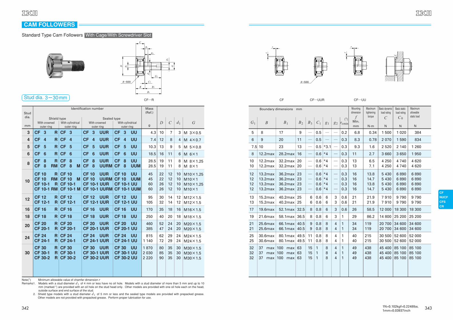
CF…R
Note(1) Minimum allowable value of chamfer dimension rRemarks1. Models with a stud diameter d1 of 4 mm or less have no oil hole. Models with a stud diameter of more than 5 mm and up to 10
mm (marked *) are provided with an oil hole on the stud head only. Other models are provided with one oil hole each on the head,outside surface and end surface of the stud.
Remarks2. Shield type models with a stud diameter d1 of 5 mm or less and the sealed type models are provided with prepacked grease.Other models are not provided with prepacked grease. Perform proper lubrication for use.
D C d1 G
CAM FOLLOWERS
Standard Type Cam Followers With Cage/With Screwdriver Slot
Stud dia. 3-30mm
Studdia.
mmWith crowned
outer ring
342
G1
8
1010
12121212
1313
17
19
2121
2525
323232
B2
16
2020
23232323
2525
32.5
36.5
40.540.5
49.549.5
636363
B3
─
──
────
66
8
8
99
1111
151515
3
44
4444
66
6
8
88
1212
171717
C1 g1 g2 H
0.6 ─
──
────
66
6
6
88
88
888
─
──
────
33
3
3
44
44
444
0.60.6
0.60.60.60.6
0.60.6
0.8
0.8
0.80.8
0.80.8
111
0.3
0.30.3
0.30.30.30.3
0.60.6
0.6
1
11
11
111
rsmin
11
1313
16161616
2121
26
29
3434
4040
494949
2.7
6.57.1
13.814.713.814.7
21.921.9
58.5
86.2
119119
215215
438438438
6 980
8 1708 170
9 5709 5709 5709 570
13 50013 500
20 700
25 300
33 20033 200
46 60046 600
67 70067 70067 700
8 500
11 20011 200
14 50014 50014 50014 500
19 70019 700
37 600
51 300
64 50064 500
92 00092 000
144 000144 000144 000
1 950
4 6204 620
8 650 8 6508 650 8 650
13 20013 200
23 200
31 100
37 50037 500
52 00052 000
85 90085 90085 900
Bmax
12.2
12.212.2
13.213.213.213.2
15.215.2
19.6
21.6
25.625.6
30.630.6
373737
B1max
28.2
32.232.2
36.236.236.236.2
40.240.2
52.1
58.1
66.166.1
80.180.1
100100100
(1)
Mountingdimension
fMin.mm
Maximumtightening
torque
N-m
Basic dynamicload rating
C
N
Basic staticload rating
C0
N
Maximumallowablestatic load
N
Boundary dimensions mm
G
M 6×1
M 8×1.25M 8×1
M10×1.25M10×1M10×1.25M10×1
M12×1.5M12×1.5
M16×1.5
M18×1.5
M20×1.5M20×1.5
M24×1.5M24×1.5
M30×1.5M30×1.5M30×1.5
CF…VB CF…VBUUR CF…VBUU
3451N=0.102kgf=0.2248lbs.1mm=0.03937inch
Studdia.
mmWith crowned
outer ring
Shield typeWith cylindrical
outer ringWith crowned
outer ringWith cylindrical
outer ring
Mass (Ref.)
Identification number
gD C d1
6
8
10
12
16
18
20
24
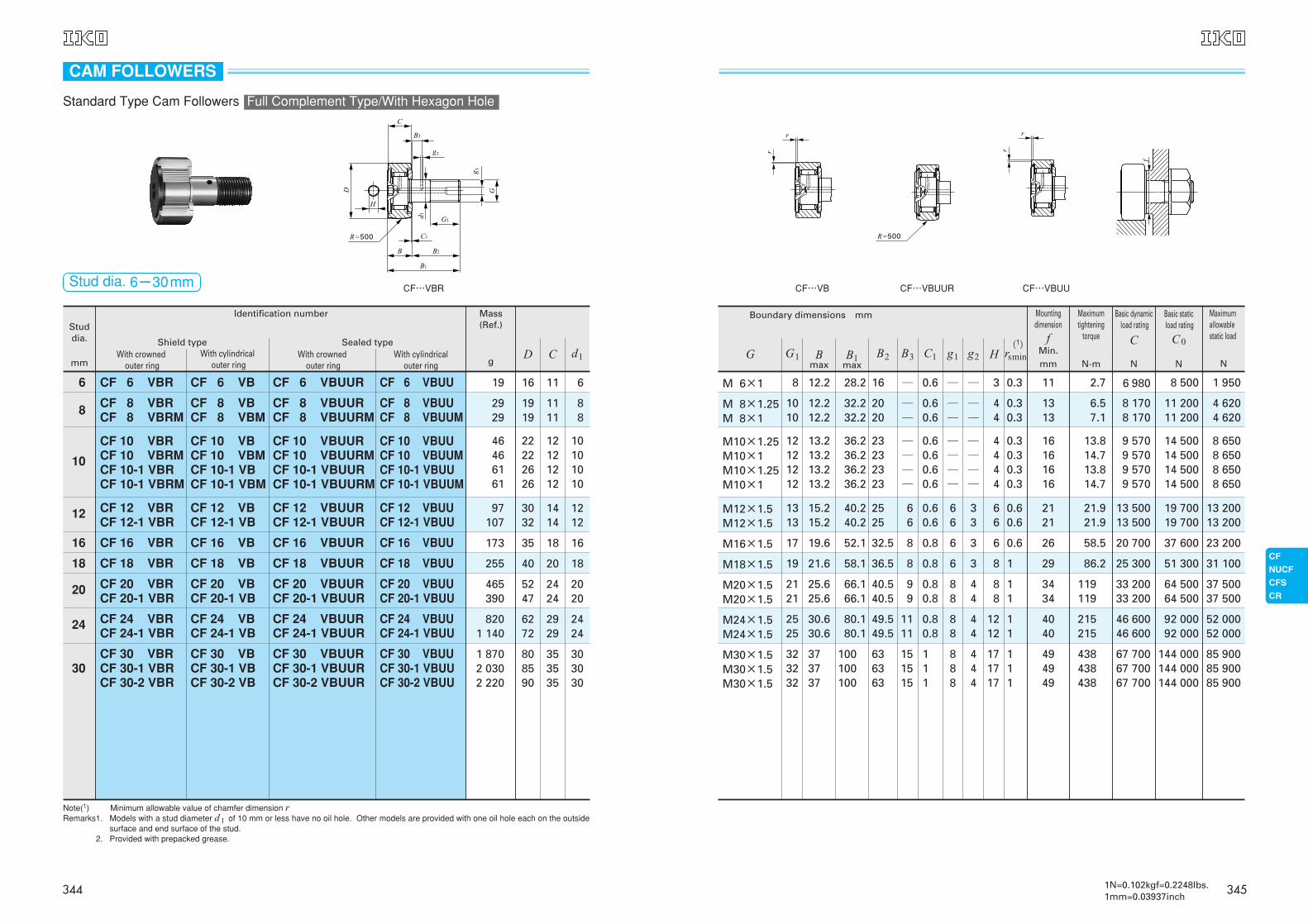
30
CF 6 VBR
CF 8 VBRCF 8 VBRM
CF 10 VBRCF 10 VBRMCF 10-1 VBRCF 10-1 VBRM
CF 12 VBRCF 12-1 VBR
CF 16 VBR
CF 18 VBR
CF 20 VBRCF 20-1 VBR
CF 24 VBRCF 24-1 VBR
CF 30 VBRCF 30-1 VBRCF 30-2 VBR
CF 6 VBUUR
CF 8 VBUURCF 8 VBUURM
CF 10 VBUURCF 10 VBUURMCF 10-1 VBUURCF 10-1 VBUURM
CF 12 VBUURCF 12-1 VBUUR
CF 16 VBUUR
CF 18 VBUUR
CF 20 VBUURCF 20-1 VBUUR
CF 24 VBUURCF 24-1 VBUUR
CF 30 VBUURCF 30-1 VBUURCF 30-2 VBUUR
CF 6 VBUU
CF 8 VBUUCF 8 VBUUM
CF 10 VBUUCF 10 VBUUMCF 10-1 VBUUCF 10-1 VBUUM
CF 12 VBUUCF 12-1 VBUU
CF 16 VBUU
CF 18 VBUU
CF 20 VBUUCF 20-1 VBUU
CF 24 VBUUCF 24-1 VBUU
CF 30 VBUUCF 30-1 VBUUCF 30-2 VBUU
CF 6 VB
CF 8 VBCF 8 VBM
CF 10 VBCF 10 VBMCF 10-1 VBCF 10-1 VBM
CF 12 VBCF 12-1 VB
CF 16 VB
CF 18 VB
CF 20 VBCF 20-1 VB
CF 24 VBCF 24-1 VB
CF 30 VBCF 30-1 VBCF 30-2 VB
Sealed type
19
2929
46466161
97107
173
255
465390
8201 140
1 8702 0302 220
16
1919
22222626
3032
35
40
5247
6272
808590
11
1111
12121212
1414
18
20
2424
2929
353535
6
88
10101010
1212
16
18
2020
2424
303030
CF…VBR
Note(1) Minimum allowable value of chamfer dimension rRemarks1. Models with a stud diameter d1 of 10 mm or less have no oil hole. Other models are provided with one oil hole each on the outside
surface and end surface of the stud.Remarks2. Provided with prepacked grease.
Stud dia. 6-30mm
CAM FOLLOWERS
Standard Type Cam Followers Full Complement Type/With Hexagon Hole
344
8
1010
12121212
1313
17
19
2121
2525
323232
16
2020
23232323
2525
32.5
36.5
40.540.5
49.549.5
636363
─
──
────
66
8
8
99
1111
151515
0.6 *4
*4*4
*4*4*4*4
66
6
6
88
88
888
─
──
────
33
3
3
44
44
444
0.60.6
0.60.60.60.6
0.60.6
0.8
0.8
0.80.8
0.80.8
111
0.3
0.30.3
0.30.30.30.3
0.60.6
0.6
1
11
11
111
11
1313
16161616
2121
26
29
3434
4040
494949
2.7
6.57.1
13.814.713.814.7
21.921.9
58.5
86.2
119119
215215
438438438
6 980
8 1708 170
9 5709 5709 5709 570
13 50013 500
20 700
25 300
33 20033 200
46 60046 600
67 70067 70067 700
8 500
11 20011 200
14 50014 50014 50014 500
19 70019 700
37 600
51 300
64 50064 500
92 00092 000
144 000144 000144 000
1 950
4 6204 620
8 6508 6508 6508 650
13 20013 200
23 200
31 100
37 50037 500
52 00052 000
85 90085 90085 900
12.2
12.212.2
13.213.213.213.2
15.215.2
19.6
21.6
25.625.6
30.630.6
373737
28.2
32.232.2
36.236.236.236.2
40.240.2
52.1
58.1
66.166.1
80.180.1
100100100
(1)
Boundary dimensions mm
M 6×1
M 8×1.25M 8×1
M10×1.25M10×1M10×1.25M10×1
M12×1.5M12×1.5
M16×1.5
M18×1.5
M20×1.5M20×1.5
M24×1.5M24×1.5
M30×1.5M30×1.5M30×1.5
CF…V CF…VUUR CF…VUU
G1 B2 B3 C1 g1 g2 rsminBmax
B1max
Mountingdimension
fMin.mm
Maximumtightening
torque
N-m
Basic dynamicload rating
C
N
Basic staticload rating
C0
N
Maximumallowablestatic load
NG
3471N=0.102kgf=0.2248lbs.1mm=0.03937inch
Studdia.
mmWith crowned
outer ring
Shield typeWith cylindrical
outer ringWith crowned
outer ringWith cylindrical
outer ring
Mass (Ref.)
Identification number
g
6
8
10
12
16
18
20
24
30
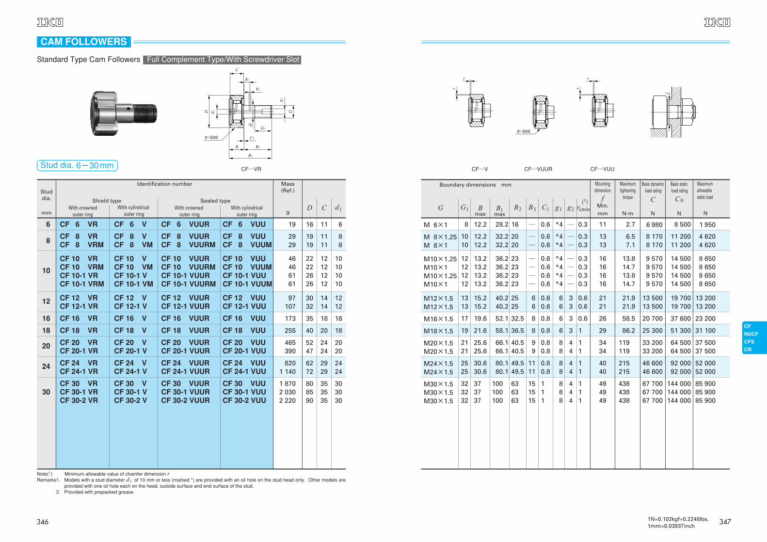
CF 6 VR
CF 8 VRCF 8 VRM
CF 10 VRCF 10 VRMCF 10-1 VRCF 10-1 VRM
CF 12 VRCF 12-1 VR
CF 16 VR
CF 18 VR
CF 20 VRCF 20-1 VR
CF 24 VRCF 24-1 VR
CF 30 VRCF 30-1 VRCF 30-2 VR
CF 6 VUUR
CF 8 VUURCF 8 VUURM
CF 10 VUURCF 10 VUURMCF 10-1 VUURCF 10-1 VUURM
CF 12 VUURCF 12-1 VUUR
CF 16 VUUR
CF 18 VUUR
CF 20 VUURCF 20-1 VUUR
CF 24 VUURCF 24-1 VUUR
CF 30 VUURCF 30-1 VUURCF 30-2 VUUR
CF 6 VUU
CF 8 VUUCF 8 VUUM
CF 10 VUUCF 10 VUUMCF 10-1 VUUCF 10-1 VUUM
CF 12 VUUCF 12-1 VUU
CF 16 VUU
CF 18 VUU
CF 20 VUUCF 20-1 VUU
CF 24 VUUCF 24-1 VUU
CF 30 VUUCF 30-1 VUUCF 30-2 VUU
CF 6 V
CF 8 VCF 8 VM
CF 10 VCF 10 VMCF 10-1 VCF 10-1 VM
CF 12 VCF 12-1 V
CF 16 V
CF 18 V
CF 20 VCF 20-1 V
CF 24 VCF 24-1 V
CF 30 VCF 30-1 VCF 30-2 V
Sealed type
19
2929
46466161
97107
173
255
465390
8201 140
1 8702 0302 220
16
1919
22222626
3032
35
40
5247
6272
808590
11
1111
12121212
1414
18
20
2424
2929
353535
6
88
10101010
1212
16
18
2020
2424
303030
CF…VR
Note(1) Minimum allowable value of chamfer dimension rRemarks1. Models with a stud diameter d1 of 10 mm or less (marked *) are provided with an oil hole on the stud head only. Other models are
provided with one oil hole each on the head, outside surface and end surface of the stud.Remarks2. Provided with prepacked grease.
Stud dia. 6-30mm
D C d1
CAM FOLLOWERS
Standard Type Cam Followers Full Complement Type/With Screwdriver Slot
346
Studdia.
mm
Mass (Ref.)
Identification number
g
3
4
5
6
8
10
12
16
18
20
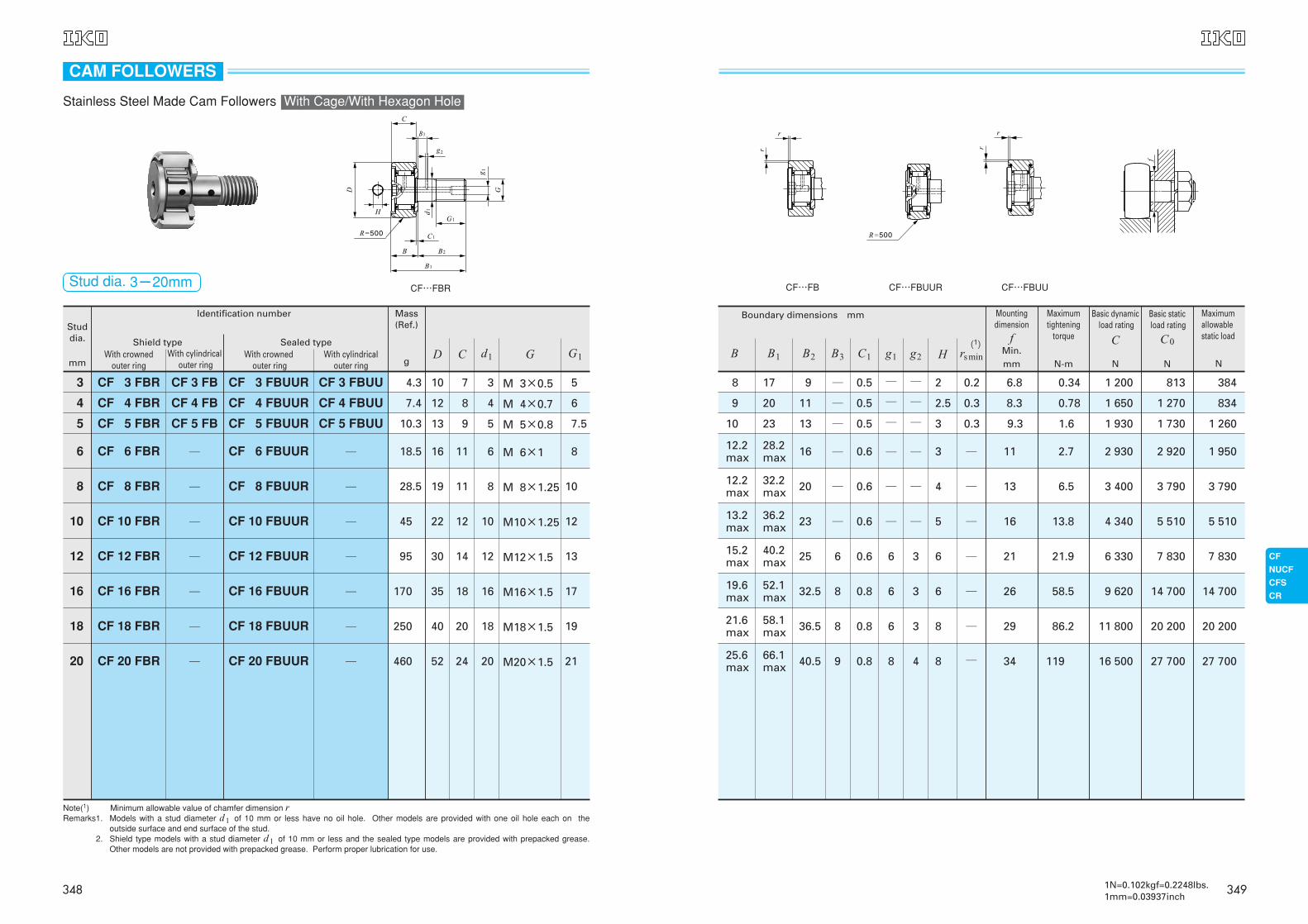
CF 3 FBR
CF 4 FBR
CF 5 FBR
CF 6 FBR
CF 8 FBR
CF 10 FBR
CF 12 FBR
CF 16 FBR
CF 18 FBR
CF 20 FBR
CF 6 FBUUR
CF 8 FBUUR
CF 10 FBUUR
CF 12 FBUUR
CF 16 FBUUR
CF 18 FBUUR
CF 20 FBUUR
CF 3 FB
CF 4 FB
CF 5 FB
CF 3 FBUUR
CF 4 FBUUR
CF 5 FBUUR
CF 3 FBUU
CF 4 FBUU
CF 5 FBUU
─
─
─
─
─
─
─
─
─
─
─
─
─
─
4.3
7.4
10.3
18.5
28.5
45
95
170
250
460
10
12
13
16
19
22
30
35
40
52
7
8
9
11
11
12
14
18
20
24
3
4
5
6
8
10
12
16
18
20
M 3×0.5
M 4×0.7
M 5×0.8
M 6×1
M 8×1.25
M10×1.25
M12×1.5
M16×1.5
M18×1.5
M20×1.5
5
6
7.5
8
10
12
13
17
19
21
CF…FBR
With crowned outer ring
Shield typeWith cylindrical
outer ringWith crowned
outer ring
Sealed typeWith cylindrical
outer ring
Note(1) Minimum allowable value of chamfer dimension rRemarks1. Models with a stud diameter d1 of 10 mm or less have no oil hole. Other models are provided with one oil hole each on the
outside surface and end surface of the stud.Remarks2. Shield type models with a stud diameter d1 of 10 mm or less and the sealed type models are provided with prepacked grease.
Other models are not provided with prepacked grease. Perform proper lubrication for use.
D C d1 G G1
CAM FOLLOWERS
Stainless Steel Made Cam Followers With Cage/With Hexagon Hole
Stud dia. 3-20mm
348
9
11
13
16
20
23
25
32.5
36.5
40.5
─
─
─
─
─
─
6
8
8
9
0.5
0.5
0.5
0.6
0.6
0.6
0.6
0.8
0.8
0.8
─
─
─
─
─
─
6
6
6
8
─
─
─
─
─
─
3
3
3
4
2
2.5
3
3
4
5
6
6
8
8
0.2
0.3
0.3
─
─
─
─
─
─
─
6.8
8.3
9.3
11
13
16
21
26
29
34
0.34
0.78
1.6
2.7
6.5
13.8
21.9
58.5
86.2
119
1 200
1 650
1 930
2 930
3 400
4 340
6 330
9 620
11 800
16 500
813
1 270
1 730
2 920
3 790
5 510
7 830
14 700
20 200
27 700
384
834
1 260
1 950
3 790
5 510
7 830
14 700
20 200
27 700
(1)
Boundary dimensions mm
8
9
10
12.2max
12.2max
13.2max
15.2max
19.6max
21.6max
25.6max
17
20
23
28.2max
32.2max
36.2max
40.2max
52.1max
58.1max
66.1max
CF…FB CF…FBUUR CF…FBUU
B2 B3 C1 g1 g2 rs minB1 B1
Mountingdimension
fMin.mm
Maximumtightening
torque
N-m
Basic dynamicload rating
C
N
Basic staticload rating
C0
N
Maximumallowablestatic load
NH
3491N=0.102kgf=0.2248lbs.1mm=0.03937inch
Studdia.
mmWith crowned
outer ring
Shield typeWith cylindrical
outer ringWith crowned
outer ringWith cylindrical
outer ring
Mass (Ref.)
Identification number
g
6
8
10
12
16
18
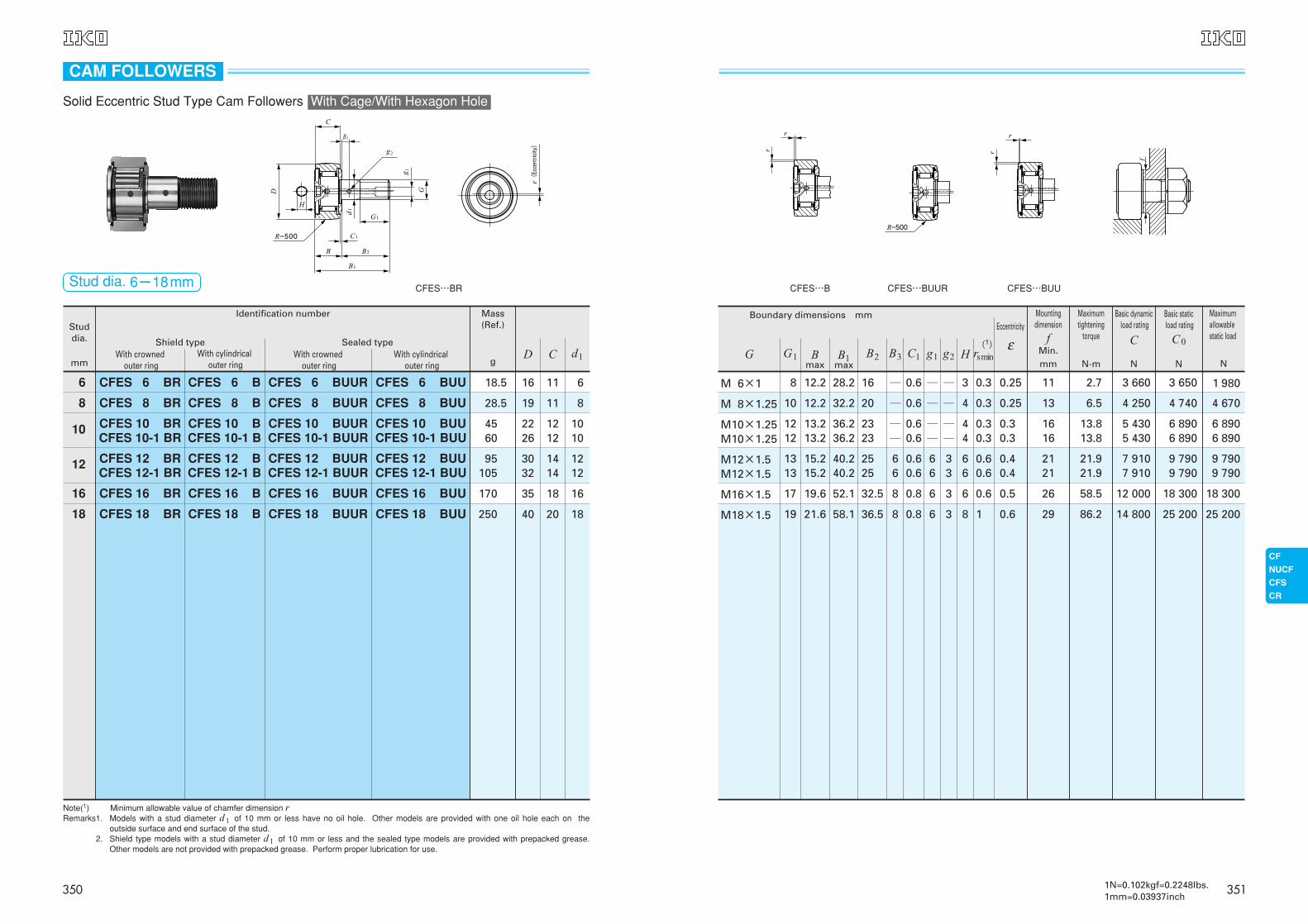
CFES 6 BR
CFES 8 BR
CFES 10 BRCFES 10-1 BR
CFES 12 BRCFES 12-1 BR
CFES 16 BR
CFES 18 BR
CFES 6 BUUR
CFES 8 BUUR
CFES 10 BUURCFES 10-1 BUUR
CFES 12 BUURCFES 12-1 BUUR
CFES 16 BUUR
CFES 18 BUUR
CFES 6 BUU
CFES 8 BUU
CFES 10 BUUCFES 10-1 BUU
CFES 12 BUUCFES 12-1 BUU
CFES 16 BUU
CFES 18 BUU
CFES 6 B
CFES 8 B
CFES 10 BCFES 10-1 B
CFES 12 BCFES 12-1 B
CFES 16 B
CFES 18 B
Sealed type
18.5
28.5
4560
95105
170
250
16
19
2226
3032
35
40
11
11
1212
1414
18
20
6
8
1010
1212
16
18
CFES…BR
Note(1) Minimum allowable value of chamfer dimension rRemarks1. Models with a stud diameter d1 of 10 mm or less have no oil hole. Other models are provided with one oil hole each on the
outside surface and end surface of the stud.Remarks2. Shield type models with a stud diameter d1 of 10 mm or less and the sealed type models are provided with prepacked grease.
Other models are not provided with prepacked grease. Perform proper lubrication for use.
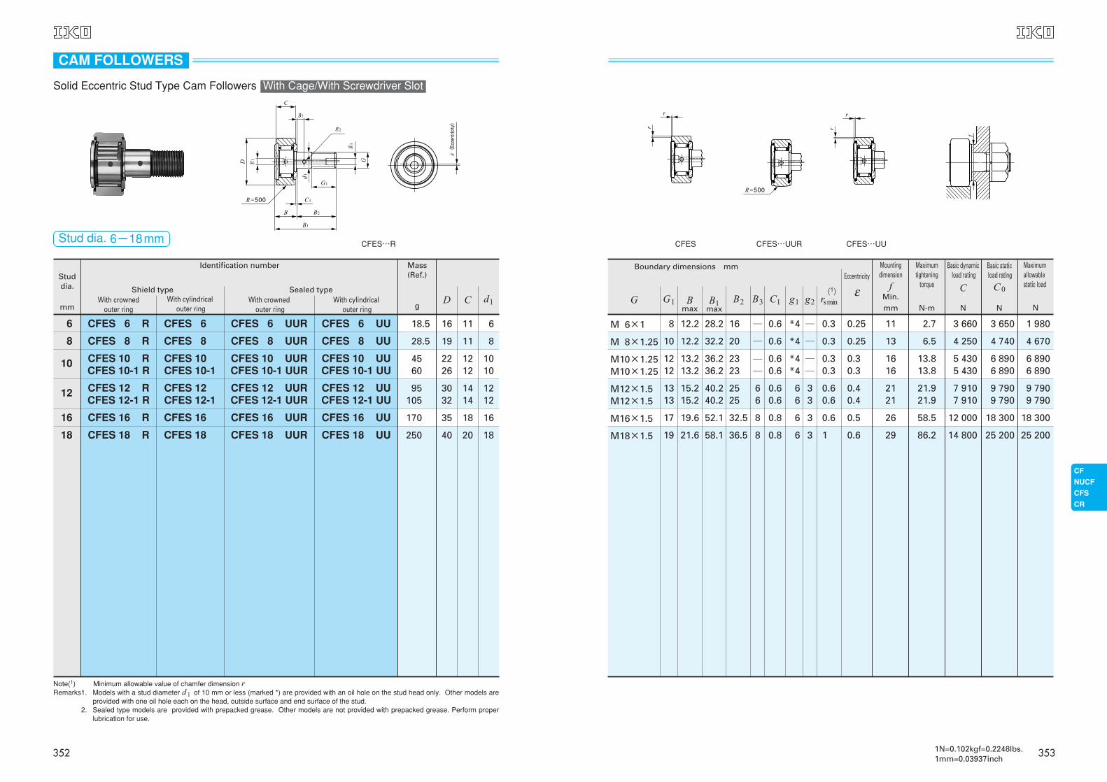
Stud dia. 6-18mm
D C d1
(Ec
cent
ricity)
Solid Eccentric Stud Type Cam Followers With Cage/With Hexagon Hole
CAM FOLLOWERS
350
8
10
1212
1313
17
19
16
20
2323
2525
32.5
36.5
─
─
──
66
8
8
3
4
44
66
6
8
0.6 ─
─
──
66
6
6
─
─
──
33
3
3
0.6
0.60.6
0.60.6
0.8
0.8
0.3
0.3
0.30.3
0.60.6
0.6
1
11
13
1616
2121
26
29
2.7
6.5
13.813.8
21.921.9
58.5
86.2
3 660
4 250
5 4305 430
7 9107 910
12 000
14 800
3 650
4 740
6 8906 890
9 7909 790
18 300
25 200
1 980
4 670
6 8906 890
9 7909 790
18 300
25 200
12.2
12.2
13.213.2
15.215.2
19.6
21.6
28.2
32.2
36.236.2
40.240.2
52.1
58.1
(1)
Boundary dimensions mm
M 6×1
M 8×1.25
M10×1.25M10×1.25
M12×1.5M12×1.5
M16×1.5
M18×1.5
CFES…B CFES…BUUR CFES…BUU
Eccentricity
ε
0.25
0.25
0.30.3
0.40.4
0.5
0.6
G1 B2 B3 C1 g1 g2 H rsminBmax
B1max
Mountingdimension
fMin.mm
Maximumtightening
torque
N-m
Basic dynamicload rating
C
N
Basic staticload rating
C0
N
Maximumallowablestatic load
NG
3511N=0.102kgf=0.2248lbs.1mm=0.03937inch
8
10
1212
1313
17
19
16
20
2323
2525
32.5
36.5
─
─
──
66
8
8
0.6 *4
*4
*4*4
66
6
6
─
─
──
33
3
3
0.6
0.60.6
0.60.6
0.8
0.8
0.3
0.3
0.30.3
0.60.6
0.6
1
11
13
1616
2121
26
29
2.7
6.5
13.813.8
21.921.9
58.5
86.2
3 660
4 250
5 4305 430
7 9107 910
12 000
14 800
3 650
4 740
6 8906 890
9 7909 790
18 300
25 200
1 980
4 670
6 8906 890
9 7909 790
18 300
25 200
12.2
12.2
13.213.2
15.215.2
19.6
21.6
28.2
32.2
36.236.2
40.240.2
52.1
58.1
(1)
Boundary dimensions mm
M 6×1
M 8×1.25
M10×1.25M10×1.25
M12×1.5M12×1.5
M16×1.5
M18×1.5
CFES CFES…UUR CFES…UU
0.25
0.25
0.30.3
0.40.4
0.5
0.6
Eccentricity
εG1 B2 B3 C1 g1 g2 rsminB
maxB1
max
Mountingdimension
fMin.mm
Maximumtightening
torque
N-m
Basic dynamicload rating
C
N
Basic staticload rating
C0
N
Maximumallowablestatic load
NG
3531N=0.102kgf=0.2248lbs.1mm=0.03937inch
Studdia.
mmWith crowned
outer ring
Shield typeWith cylindrical
outer ringWith crowned
outer ringWith cylindrical
outer ring
Mass (Ref.)
Identification number
g
6
8
10
12
16
18
CFES 6 R
CFES 8 R
CFES 10 RCFES 10-1 R
CFES 12 RCFES 12-1 R
CFES 16 R
CFES 18 R
CFES 6 UUR
CFES 8 UUR
CFES 10 UURCFES 10-1 UUR
CFES 12 UURCFES 12-1 UUR
CFES 16 UUR
CFES 18 UUR
CFES 6 UU
CFES 8 UU
CFES 10 UUCFES 10-1 UU
CFES 12 UUCFES 12-1 UU
CFES 16 UU
CFES 18 UU
CFES 6
CFES 8
CFES 10 CFES 10-1
CFES 12 CFES 12-1
CFES 16
CFES 18
Sealed type
18.5
28.5
4560
95105
170
250
16
19
2226
3032
35
40
11
11
1212
1414
18
20
6
8
1010
1212
16
18
CFES…R
Note(1) Minimum allowable value of chamfer dimension rRemarks1. Models with a stud diameter d1 of 10 mm or less (marked *) are provided with an oil hole on the stud head only. Other models are
provided with one oil hole each on the head, outside surface and end surface of the stud.Remarks2. Sealed type models are provided with prepacked grease. Other models are not provided with prepacked grease. Perform proper
lubrication for use.
Stud dia. 6-18mm
D C d1
(Ec
cent
ricity)
CAM FOLLOWERS
Solid Eccentric Stud Type Cam Followers With Cage/With Screwdriver Slot
352
Outsidediameter of
eccentriccollarmm
With crownedouter ring
Shield typeWith cylindrical
outer ringWith crowned
outer ringWith cylindrical
outer ring
Mass (Ref.)
Identification number
g
9
11
13
16
22
24
27
33
41
CFE 6 BR
CFE 8 BR
CFE 10 BRCFE 10-1 BR
CFE 12 BRCFE 12-1 BR
CFE 16 BR
CFE 18 BR
CFE 20 BRCFE 20-1 BR
CFE 24 BRCFE 24-1 BR
CFE 30 BRCFE 30-1 BRCFE 30-2 BR
CFE 6 BUUR
CFE 8 BUUR
CFE 10 BUURCFE 10-1 BUUR
CFE 12 BUURCFE 12-1 BUUR
CFE 16 BUUR
CFE 18 BUUR
CFE 6 BUU
CFE 8 BUU
CFE 10 BUUCFE 10-1 BUU
CFE 12 BUUCFE 12-1 BUU
CFE 16 BUU
CFE 18 BUU
CFE 6 B
CFE 8 B
CFE 10 BCFE 10-1 B
CFE 12 BCFE 12-1 B
CFE 16 B
CFE 18 B
CFE 20 BUURCFE 20-1 BUUR
CFE 24 BUURCFE 24-1 BUUR
CFE 30 BUURCFE 30-1 BUURCFE 30-2 BUUR
CFE 20 BUUCFE 20-1 BUU
CFE 24 BUUCFE 24-1 BUU
CFE 30 BUUCFE 30-1 BUUCFE 30-2 BUU
CFE 20 BCFE 20-1 B
CFE 24 BCFE 24-1 B
CFE 30 BCFE 30-1 BCFE 30-2 B
Sealed type
20.5
32
49.565
105115
190
280
500425
8951 220
2 0302 1902 380
16
19
2226
3032
35
40
5247
6272
808590
11
11
1212
1414
18
20
2424
2929
353535
9
11
1313
1616
22
24
2727
3333
414141
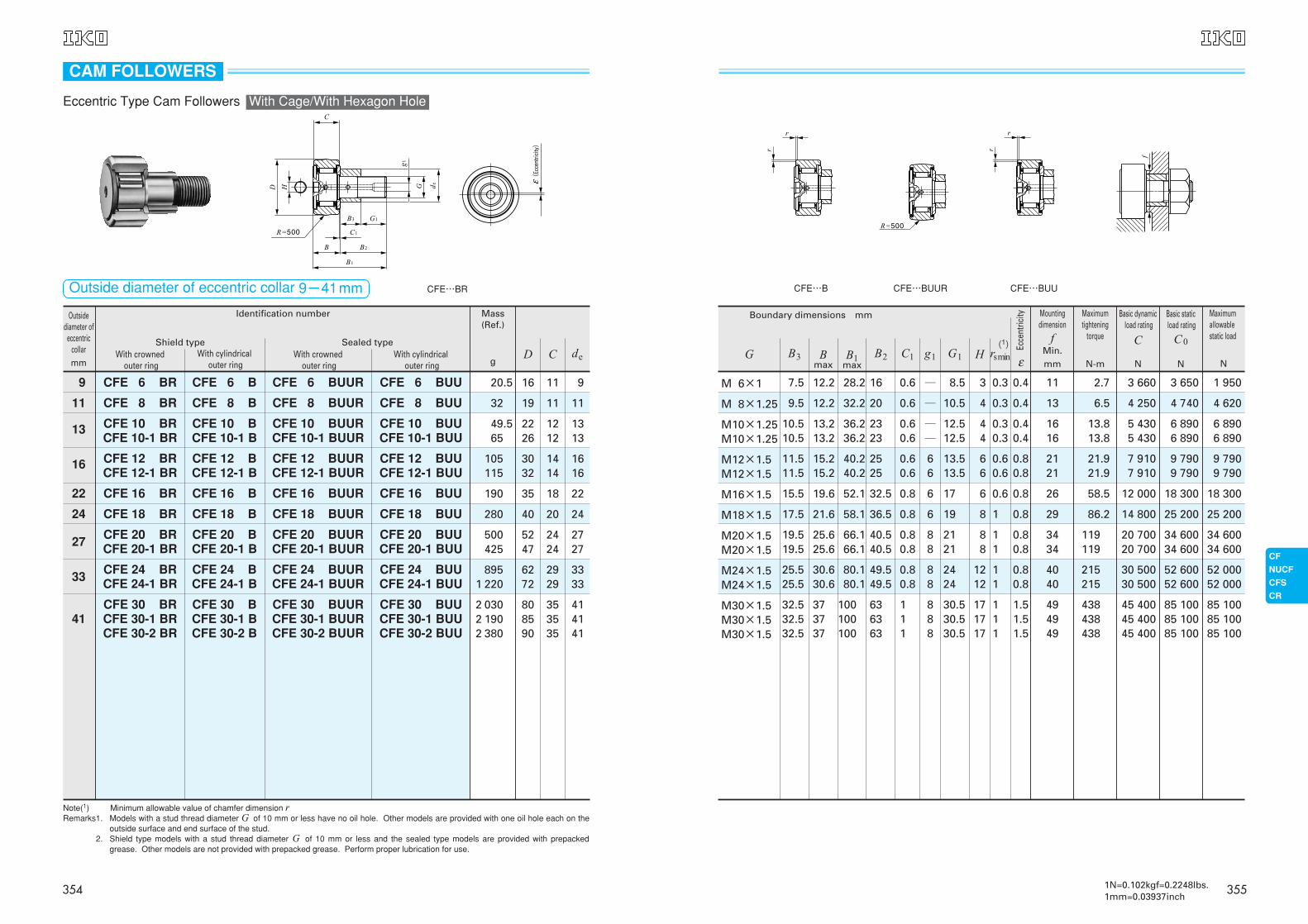
CFE…BR
Note(1) Minimum allowable value of chamfer dimension rRemarks1. Models with a stud thread diameter G of 10 mm or less have no oil hole. Other models are provided with one oil hole each on the
outside surface and end surface of the stud.Remarks2. Shield type models with a stud thread diameter G of 10 mm or less and the sealed type models are provided with prepacked
grease. Other models are not provided with prepacked grease. Perform proper lubrication for use.
Outside diameter of eccentric collar 9-41mm
D C de
(Ec
cent
ricity)
CAM FOLLOWERS
Eccentric Type Cam Followers With Cage/With Hexagon Hole
354
8.5
10.5
12.512.5
13.513.5
17
19
2121
16
20
2323
2525
32.5
36.5
40.540.5
7.5
9.5
10.510.5
11.511.5
15.5
17.5
19.519.5
3
4
44
66
6
8
88
H
0.6 ─
─
──
66
6
6
88
0.4
0.4
0.40.4
0.80.8
0.8
0.8
0.80.8
0.6
0.60.6
0.60.6
0.8
0.8
0.80.8
0.3
0.3
0.30.3
0.60.6
0.6
1
11
11
13
1616
2121
26
29
3434
2.7
6.5
13.813.8
21.921.9
58.5
86.2
119119
3 660
4 250
5 4305 430
7 9107 910
12 000
14 800
20 70020 700
3 650
4 740
6 8906 890
9 7909 790
18 300
25 200
34 60034 600
1 950
4 620
6 8906 890
9 7909 790
18 300
25 200
34 60034 600
12.2
12.2
13.213.2
15.215.2
19.6
21.6
25.625.6
28.2
32.2
36.236.2
40.240.2
52.1
58.1
66.166.1
(1)
Boundary dimensions mm
M 6×1
M 8×1.25
M10×1.25M10×1.25
M12×1.5M12×1.5
M16×1.5
M18×1.5
M20×1.5M20×1.5
2424
49.549.5
25.525.5
1212
88
0.80.8
0.80.8
11
4040
215215
30 50030 500
52 60052 600
52 00052 000
30.630.6
80.180.1
M24×1.5M24×1.5
30.530.530.5
636363
32.532.532.5
171717
888
1.51.51.5
111
111
494949
438438438
45 40045 40045 400
85 10085 10085 100
85 10085 10085 100
373737
100100100
M30×1.5M30×1.5M30×1.5
CFE…B CFE…BUUR CFE…BUU
εB3 B2 C1 g1 G1 rsminB
maxB1
max
Mountingdimension
fMin.mm
Maximumtightening
torque
N-m
Basic dynamicload rating
C
N
Basic staticload rating
C0
N
Maximumallowablestatic load
NG
Ecce
ntric
ity
3551N=0.102kgf=0.2248lbs.1mm=0.03937inch
8.5
10.5
12.512.5
13.513.5
17
19
2121
16
20
2323
2525
32.5
36.5
40.540.5
7.5
9.5
10.510.5
11.511.5
15.5
17.5
19.519.5
0.6 *4
*4
*4*4
66
6
6
88
0.4
0.4
0.40.4
0.80.8
0.8
0.8
0.80.8
0.6
0.60.6
0.60.6
0.8
0.8
0.80.8
0.3
0.3
0.30.3
0.60.6
0.6
1
11
11
13
1616
2121
26
29
3434
2.7
6.5
13.813.8
21.921.9
58.5
86.2
119119
3 660
4 250
5 4305 430
7 9107 910
12 000
14 800
20 70020 700
3 650
4 740
6 8906 890
9 7909 790
18 300
25 200
34 60034 600
1 950
4 620
6 8906 890
9 7909 790
18 300
25 200
34 60034 600
12.2
12.2
13.213.2
15.215.2
19.6
21.6
25.625.6
28.2
32.2
36.236.2
40.240.2
52.1
58.1
66.166.1
(1)
Boundary dimensions mm
M 6×1
M 8×1.25
M10×1.25M10×1.25
M12×1.5M12×1.5
M16×1.5
M18×1.5
M20×1.5M20×1.5
2424
49.549.5
25.525.5
88
0.80.8
0.80.8
11
4040
215215
30 50030 500
52 60052 600
52 00052 000
30.630.6
80.180.1
M24×1.5M24×1.5
30.530.530.5
636363
32.532.532.5
888
1.51.51.5
111
111
494949
438438438
45 40045 40045 400
85 10085 10085 100
85 10085 10085 100
373737
100100100
M30×1.5M30×1.5M30×1.5
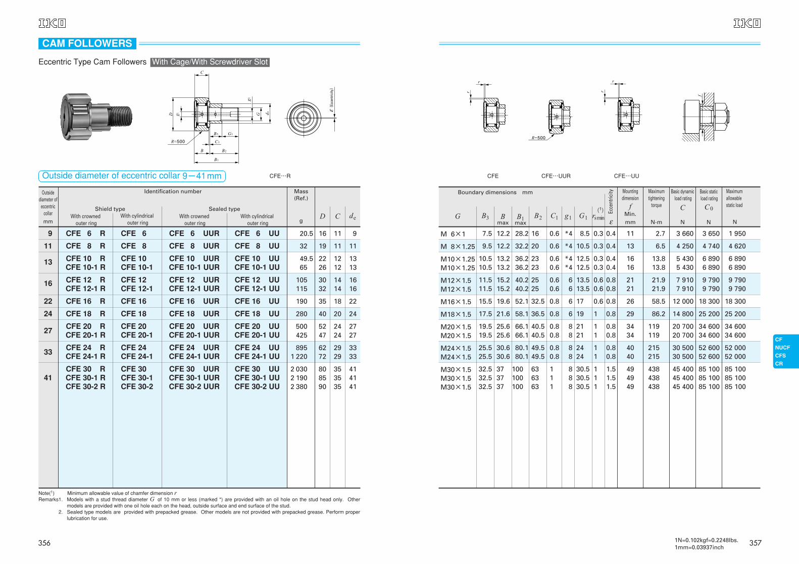
CFE CFE…UUR CFE…UU
εB3 B2 C1 g1 G1 rsminB
maxB1
max
Mountingdimension
fMin.mm
Maximumtightening
torque
N-m
Basic dynamicload rating
C
N
Basic staticload rating
C0
N
Maximumallowablestatic load
NG
Ecce
ntric
ity
3571N=0.102kgf=0.2248lbs.1mm=0.03937inch
Outsidediameter of
eccentriccollarmm
With crownedouter ring
Shield typeWith cylindrical
outer ringWith crowned
outer ringWith cylindrical
outer ring
Mass (Ref.)
Identification number
g
9
11
13
16
22
24
27
33
41
CFE 6 R
CFE 8 R
CFE 10 RCFE 10-1 R
CFE 12 RCFE 12-1 R
CFE 16 R
CFE 18 R
CFE 20 RCFE 20-1 R
CFE 24 RCFE 24-1 R
CFE 30 RCFE 30-1 RCFE 30-2 R
CFE 6 UUR
CFE 8 UUR
CFE 10 UURCFE 10-1 UUR
CFE 12 UURCFE 12-1 UUR
CFE 16 UUR
CFE 18 UUR
CFE 6 UU
CFE 8 UU
CFE 10 UUCFE 10-1 UU
CFE 12 UUCFE 12-1 UU
CFE 16 UU
CFE 18 UU
CFE 6
CFE 8
CFE 10 CFE 10-1
CFE 12 CFE 12-1
CFE 16
CFE 18
CFE 20 UURCFE 20-1 UUR
CFE 24 UURCFE 24-1 UUR
CFE 30 UURCFE 30-1 UURCFE 30-2 UUR
CFE 20 UUCFE 20-1 UU
CFE 24 UUCFE 24-1 UU
CFE 30 UUCFE 30-1 UUCFE 30-2 UU
CFE 20 CFE 20-1
CFE 24 CFE 24-1
CFE 30 CFE 30-1 CFE 30-2
Sealed type
20.5
32
49.565
105115
190
280
500425
8951 220
2 0302 1902 380
16
19
2226
3032
35
40
5247
6272
808590
11
11
1212
1414
18
20
2424
2929
353535
9
11
1313
1616
22
24
2727
3333
414141
CFE…R
Note(1) Minimum allowable value of chamfer dimension rRemarks1. Models with a stud thread diameter G of 10 mm or less (marked *) are provided with an oil hole on the stud head only. Other
models are provided with one oil hole each on the head, outside surface and end surface of the stud.Remarks2. Sealed type models are provided with prepacked grease. Other models are not provided with prepacked grease. Perform proper
lubrication for use.
D C de
(Ec
cent
ricity)
CAM FOLLOWERS
Eccentric Type Cam Followers With Cage/With Screwdriver Slot
Outside diameter of eccentric collar 9-41mm
356
8.5
10.5
12.512.5
13.513.5
17
19
2121
16
20
2323
2525
32.5
36.5
40.540.5
7.5
9.5
10.510.5
11.511.5
15.5
17.5
19.519.5
3
4
44
66
6
8
88
H
0.6 ─
─
──
66
6
6
88
0.4
0.4
0.40.4
0.80.8
0.8
0.8
0.80.8
0.6
0.60.6
0.60.6
0.8
0.8
0.80.8
0.3
0.3
0.30.3
0.60.6
0.6
1
11
11
13
1616
2121
26
29
3434
2.7
6.5
13.813.8
21.921.9
58.5
86.2
119119
6 980
8 170
9 5709 570
13 50013 500
20 700
25 300
33 20033 200
8 500
11 200
14 50014 500
19 70019 700
37 600
51 300
64 50064 500
1 950
4 620
8 6508 650
13 20013 200
23 200
31 100
37 50037 500
12.2
12.2
13.213.2
15.215.2
19.6
21.6
25.625.6
28.2
32.2
36.236.2
40.240.2
52.1
58.1
66.166.1
(1)
Boundary dimensions mm
M 6×1
M 8×1.25
M10×1.25M10×1.25
M12×1.5M12×1.5
M16×1.5
M18×1.5
M20×1.5M20×1.5
2424
49.549.5
25.525.5
1212
88
0.80.8
0.80.8
11
4040
215215
46 60046 600
92 00092 000
52 00052 000
30.630.6
80.180.1
M24×1.5M24×1.5
30.530.530.5
636363
32.532.532.5
171717
888
1.51.51.5
111
111
494949
438438438
67 70067 70067 700
144 000144 000144 000
85 90085 90085 900
373737
100100100
M30×1.5M30×1.5M30×1.5
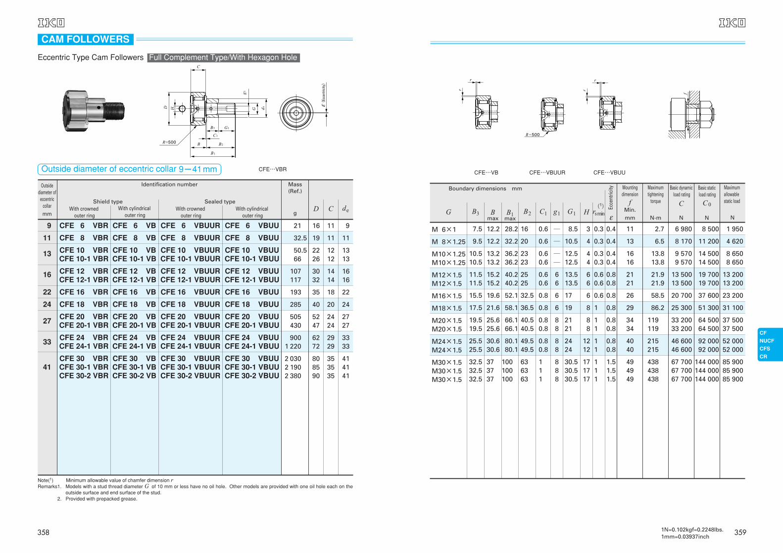
CFE…VB CFE…VBUUR CFE…VBUU
εB3 B2 C1 g1 G1 rsminB
maxB1
max
Mountingdimension
fMin.mm
Maximumtightening
torque
N-m
Basic dynamicload rating
C
N
Basic staticload rating
C0
N
Maximumallowablestatic load
NG
Ecce
ntric
ity
3591N=0.102kgf=0.2248lbs.1mm=0.03937inch
Outsidediameter of
eccentriccollarmm
With crownedouter ring
Shield typeWith cylindrical
outer ringWith crowned
outer ringWith cylindrical
outer ring
Mass (Ref.)
Identification number
g
9
11
13
16
22
24
27
33
41
CFE 6 VBR
CFE 8 VBR
CFE 10 VBRCFE 10-1 VBR
CFE 12 VBRCFE 12-1 VBR
CFE 16 VBR
CFE 18 VBR
CFE 20 VBRCFE 20-1 VBR
CFE 24 VBRCFE 24-1 VBR
CFE 30 VBRCFE 30-1 VBRCFE 30-2 VBR
CFE 6 VBUUR
CFE 8 VBUUR
CFE 10 VBUURCFE 10-1 VBUUR
CFE 12 VBUURCFE 12-1 VBUUR
CFE 16 VBUUR
CFE 18 VBUUR
CFE 6 VBUU
CFE 8 VBUU
CFE 10 VBUUCFE 10-1 VBUU
CFE 12 VBUUCFE 12-1 VBUU
CFE 16 VBUU
CFE 18 VBUU
CFE 6 VB
CFE 8 VB
CFE 10 VBCFE 10-1 VB
CFE 12 VBCFE 12-1 VB
CFE 16 VB
CFE 18 VB
CFE 20 VBUURCFE 20-1 VBUUR
CFE 24 VBUURCFE 24-1 VBUUR
CFE 30 VBUURCFE 30-1 VBUURCFE 30-2 VBUUR
CFE 20 VBUUCFE 20-1 VBUU
CFE 24 VBUUCFE 24-1 VBUU
CFE 30 VBUUCFE 30-1 VBUUCFE 30-2 VBUU
CFE 20 VBCFE 20-1 VB
CFE 24 VBCFE 24-1 VB
CFE 30 VBCFE 30-1 VBCFE 30-2 VB
Sealed type
21
32.5
50.566
107117
193
285
505430
9001 220
2 0302 1902 380
16
19
2226
3032
35
40
5247
6272
808590
11
11
1212
1414
18
20
2424
2929
353535
9
11
1313
1616
22
24
2727
3333
414141
CFE…VBR
Note(1) Minimum allowable value of chamfer dimension rRemarks1. Models with a stud thread diameter G of 10 mm or less have no oil hole. Other models are provided with one oil hole each on the
outside surface and end surface of the stud.Remarks2. Provided with prepacked grease.
D C de
(Ec
cent
ricity)
CAM FOLLOWERS
Eccentric Type Cam Followers Full Complement Type/With Hexagon Hole
Outside diameter of eccentric collar 9-41mm
358
M 8×1.25 9.5 12.2 32.2 20 0.6 *4 10.5 0.3 0.4 13 6.5 8 170 11 200 4 620
M18×1.5 17.5 21.6 58.1 36.5 0.8 6 19 1 0.8 29 86.2 25 300 51 300 31 100
M12×1.5M12×1.5
11.511.5
15.215.2
40.240.2
25
250.60.6
66
13.513.5
0.60.6
0.80.8
2121
21.921.9
13 50013 500
19 70019 700
13 20013 200
M24×1.5M24×1.5
25.525.5
30.630.6
80.180.1
49.5
49.50.80.8
88
2424
11
0.80.8
4040
215215
46 60046 600
92 00092 000
52 00052 000
Boundary dimensions mm
(1)
εM 6×1 7.5 12.2 28.2 16 0.6 *4 8.5 0.3 0.4 11 2.7 6 980 8 500 1 950
M16×1.5 15.5 19.6 52.1 32.5 0.8 6 17 0.6 0.8 26 58.5 20 700 37 600 23 200
M10×1.25M10×1.25
10.510.5
13.213.2
36.236.2
23
230.60.6
*4*4
12.512.5
0.30.3
0.40.4
1616
13.813.8
9 5709 570
14 50014 500
8 6508 650
M20×1.5M20×1.5
19.519.5
25.625.6
66.166.1
40.5
40.50.80.8
88
2121
11
0.80.8
3434
119119
33 20033 200
64 50064 500
37 50037 500
M30×1.5M30×1.5M30×1.5
32.532.532.5
373737
100100100
636363
111
888
30.530.530.5
111
1.51.51.5
494949
438438438
67 70067 70067 700
144 000144 000144 000
85 90085 90085 900
CFE…VUUCFE…VUURCFE…V
B3 B2 C1 g1 G1 rs minBmax
B1max
Mountingdimension
fMin.mm
Maximumtightening
torque
N-m
Basic dynamicload rating
C
N
Basic staticload rating
C0
N
Maximumallowablestatic load
NG
Ecce
ntric
ity
3611N=0.102kgf=0.2248lbs.1mm=0.03937inch
32.5
285
107 117
9001 220
19 11 11
40 20 24
3032
1414
1616
6272
2929
3333
Outside diameterof eccentric collar
mm
Identification number Mass (Ref.)
gWith crowned
outer ringWith cylindrical
outer ringWith crowned
outer ringWith cylindrical
outer ring
Shield type Sealed type
9 CFE 6 VR CFE 6 V CFE 6 VUUR CFE 6 VUU 21 16 11 9
11 CFE 8 VR CFE 8 V CFE 8 VUUR CFE 8 VUU
22 CFE 16 VR CFE 16 V CFE 16 VUUR CFE 16 VUU 193 35 18 22
24 CFE 18 VR CFE 18 V CFE 18 VUUR CFE 18 VUU
13CFE 10 VRCFE 10-1 VR
CFE 10 VCFE 10-1 V
CFE 10 VUURCFE 10-1 VUUR
CFE 10 VUUCFE 10-1 VUU
50.566
2226
1212
1313
16 CFE 12 VRCFE 12-1 VR
CFE 12 VCFE 12-1 V
CFE 12 VUURCFE 12-1 VUUR
CFE 12 VUUCFE 12-1 VUU
27CFE 20 VRCFE 20-1 VR
CFE 20 VCFE 20-1 V
CFE 20 VUURCFE 20-1 VUUR
CFE 20 VUUCFE 20-1 VUU
505430
5247
2424
2727
33CFE 24 VRCFE 24-1 VR
CFE 24 VCFE 24-1 V
CFE 24 VUURCFE 24-1 VUUR
CFE 24 VUUCFE 24-1 VUU
41CFE 30 VRCFE 30-1 VRCFE 30-2 VR
CFE 30 VCFE 30-1 VCFE 30-2 V
CFE 30 VUURCFE 30-1 VUURCFE 30-2 VUUR
CFE 30 VUUCFE 30-1 VUUCFE 30-2 VUU
2 0302 1902 380
808590
353535
414141
CFE…VR
Note(1) Minimum allowable value of chamfer dimension rRemarks1. Models with a stud thread diameter G of 10 mm or less (marked *) are provided with an oil hole on the stud head only. Other
models are provided with one oil hole each on the head, outside surface and end surface of the stud.Remarks2. Provided with prepacked grease.
D C de
(Ec
cent
ricity)
CAM FOLLOWERS
Eccentric Type Cam Followers Full Complement Type/With Screwdriver Slot
Outside diameter of eccentric collar 9-41mm
360
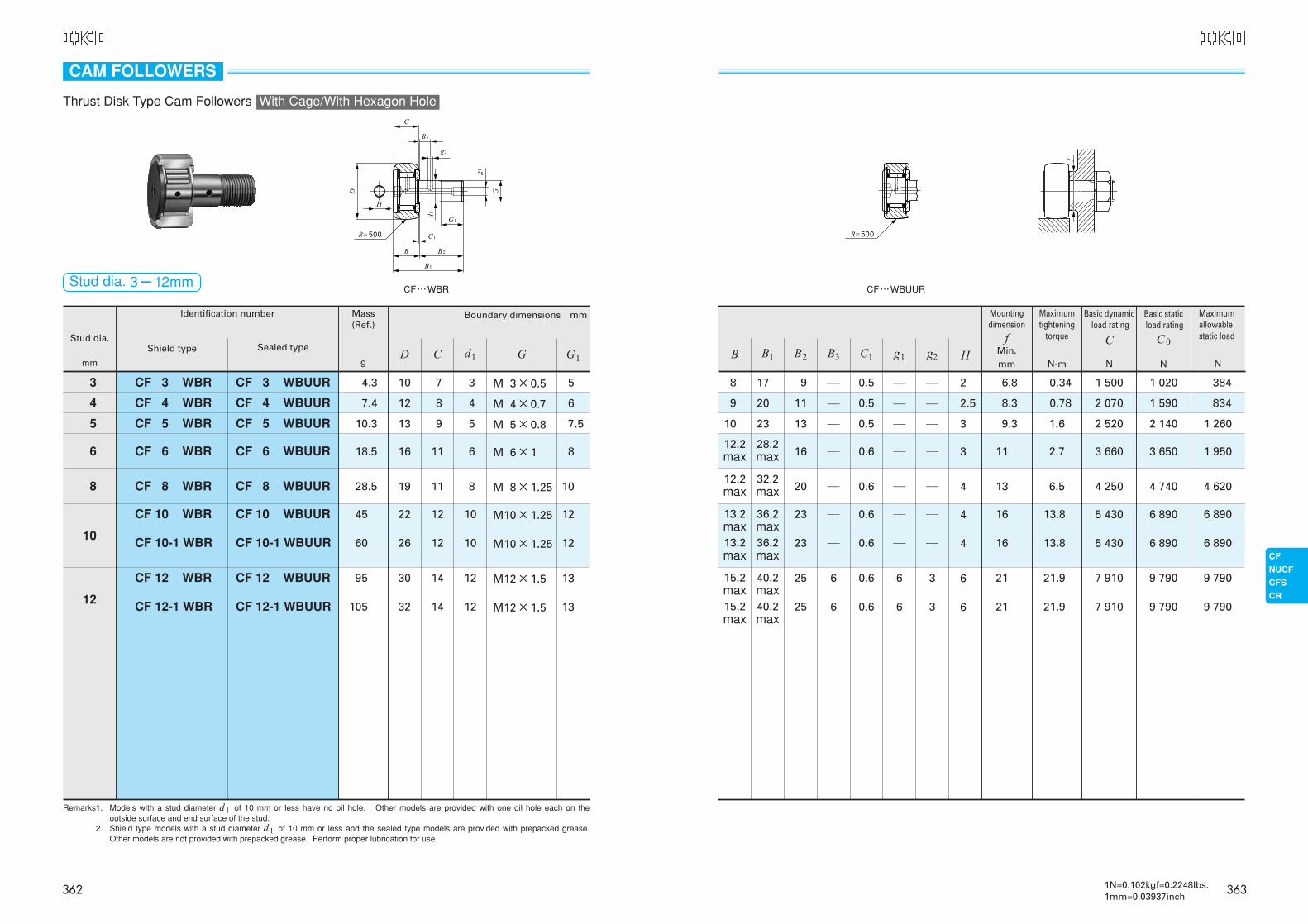
45
60
22
26
12
12
10
10
M10×1.25
M10×1.25
12
12
28.5 19 11 8 M 8×1.25 10
18.5 16 11 6 M 6×1 8
7.5
6
5
5
4
3
M 5×0.8
M 4×0.7
M 3×0.5
13
12
10
9
8
7
10.3
7.4
4.3
95
105
30
32
14
14
12
12
M12×1.5
M12×1.5
13
13
6
5
4
3
CF 6 WBUUR
CF 5 WBUUR
CF 4 WBUUR
CF 3 WBUUR
CF 6 WBR
CF 5 WBR
CF 4 WBR
CF 3 WBR
8 CF 8 WBUURCF 8 WBR
10
CF 10 WBUUR
CF 10-1 WBUUR
CF 12 WBUUR
CF 12-1 WBUUR
CF 10 WBR
CF 10-1 WBR
CF 12 WBR
CF 12-1 WBR12
CF…WBR
B1
B2B
C1R=500
G1
d1
D
g2
B3
C
g1
G
H
CAM FOLLOWERS
Thrust Disk Type Cam Followers With Cage/With Hexagon Hole
Stud dia. 3-12mm
Stud dia.
mm
Identification number
Shield type Sealed type
Mass (Ref.)
g
Boundary dimensions mm
G1GD C d1
Remarks1. Models with a stud diameter d1 of 10 mm or less have no oil hole. Other models are provided with one oil hole each on theoutside surface and end surface of the stud.
Remarks2. Shield type models with a stud diameter d1 of 10 mm or less and the sealed type models are provided with prepacked grease.Other models are not provided with prepacked grease. Perform proper lubrication for use.
362
28.2max 16 ─ 0.6 ─ ─ 3 11 2.7 3 660 3 650 1 950
10.2
9.2
8.2
32.2max 20 ─ 0.6 ─ ─ 4 13 6.5 4 250 4 740 4 620
36.2max36.2max
─
─
0.6
0.6
4
4
16
16
6 890
6 890
13.8
13.8
5 430
5 430
6 890
6 890
12.2max
12.2max
13.2max13.2max
15.2max15.2max
40.2max40.2max
25
25
6
6
6
6
0.6
0.6
3
3
6
6
21
21
9 790
9 790
21.9
21.9
7 910
7 910
9 790
9 790
23.2
20.2
17.2
13
11
19
─
─
─
0.5
0.5
0.5
─
─
─
─
─
─
3
2.5
2
9.3
8.3
6.8
1.6
0.78
0.34
2 520
2 070
1 500
2 140
1 590
1 020
1 260
834
384
H
CF…WBUUR
B3B2 C1 g1 g2B B1
R=500
f
23
23
─
─
─
─
Mountingdimension
fMin.mm
Maximumtightening
torque
N-m
Basic dynamicload rating
C
N
Basic staticload rating
C0
N
Maximumallowablestatic load
N
3631N=0.102kgf=0.2248lbs.1mm=0.03937inch
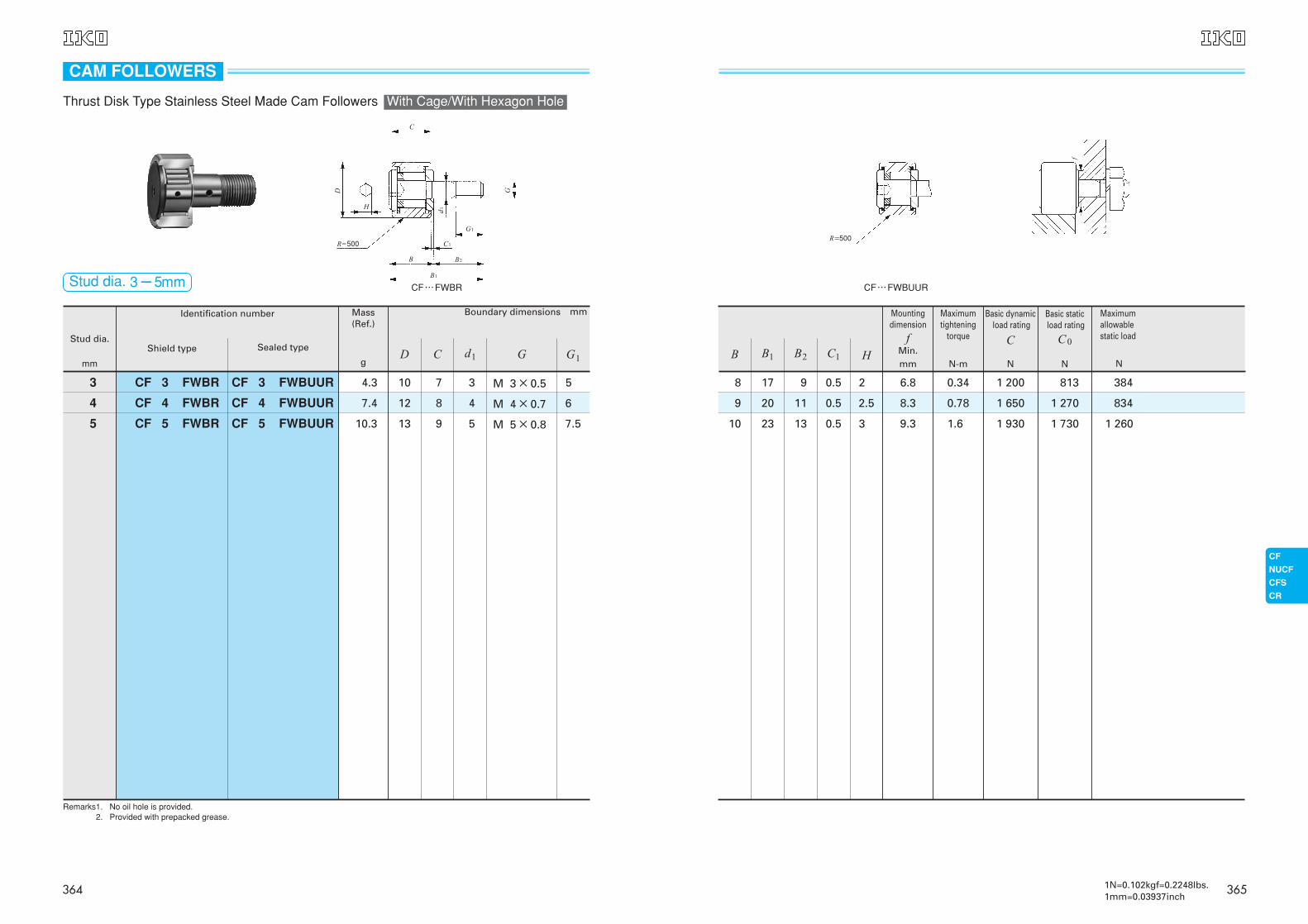
10
19
18
23
20
17
13
11
19
0.5
0.5
0.5
3
2.5
2
9.3
8.3
6.8
1.6
0.78
0.34
1 930
1 650
1 200
1 730
1 270
1 813
1 260
834
384
H
CF…FWBUUR
B2 C1B B1
Mountingdimension
fMin.mm
Maximumtightening
torque
N-m
Basic dynamicload rating
C
N
Basic staticload rating
C0
N
Maximumallowablestatic load
N
R=500
f
3651N=0.102kgf=0.2248lbs.1mm=0.03937inch
7.5
6
5
5
4
3
M 5×0.8
M 4×0.7
M 3×0.5
13
12
10
9
8
7
10.3
7.4
4.3
Stud dia.
mm
Identification number Mass (Ref.)
g
Boundary dimensions mm
Shield type
5
4
3
CF 5 FWBUUR
CF 4 FWBUUR
CF 3 FWBUUR
CF 5 FWBR
CF 4 FWBR
CF 3 FWBR
G1Sealed type
CF…FWBR
Remarks1. No oil hole is provided.Remarks2. Provided with prepacked grease.
GD C d1
R=500
B1
B2
C1
G1
d1
GD
C
H
B
CAM FOLLOWERS
Thrust Disk Type Stainless Steel Made Cam Followers With Cage/With Hexagon Hole
Stud dia. 3-5mm
364
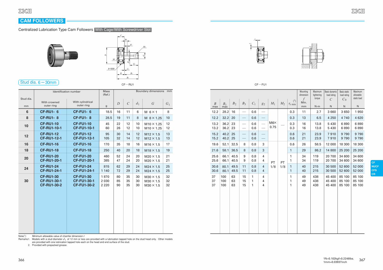
13.213.2
36.236.2
2323
──
0.60.6
──
0.30.3
1616
6 8906 890
13.813.8
5 4305 430
6 8906 890
15.215.2
40.240.2
2525
──
0.60.6
──
0.60.6
2121
9 7909 790
23.923.9
7 9107 910
9 7909 790
12.2 28.2 16 ─ 0.6 ─
M6×0.75 ─
0.3 11 2.7 3 660 3 650 1 950
12.2 32.2 20 ─ 0.6 ─ 0.3 13 6.5 4 250 4 740 4 620
19.6 52.1 32.5 8 0.8 3
PT1/8
PT1/8
0.6 26 58.5 12 000 18 300 18 300
21.6 58.1 36.5 8 0.8 3 1 29 86.2 14 800 25 200 25 200
25.625.6
66.166.1
40.540.5
99
0.80.8
44
11
3434
119119
20 70020 700
34 60034 600
34 60034 600
30.630.6
80.180.1
49.549.5
1111
0.80.8
44
11
4040
215215
30 50030 500
52 60052 600
52 00052 000
373737
100100100
636363
151515
111
444
111
494949
438438438
45 40045 40045 400
85 10085 10085 100
85 10085 10085 100
(1)
CF…FU1
M2B3B2 C1 g2 M1 rs minBmax
B1max
Mountingdimension
fMin.mm
Maximumtightening
torque
N-m
Basic dynamicload rating
C
N
Basic staticload rating
C0
N
Maximumallowablestatic load
N
3671N=0.102kgf=0.2248lbs.1mm=0.03937inch
28.5
95105
250
8151 140
19 11 8 M 8×1.25 10
3032
1414
1212
M12×1.5M12×1.5
1313
40 20 18 M18×1.5 19
6272
2929
2424
M24×1.5M24×1.5
2525
Stud dia.
mm
Identification number Mass (Ref.)
g
Boundary dimensions mm
With crowned outer ring
6 CF-FU1- 6 CF-RU1- 6 18.5 16 11 6 M 6×1
With cylindricalouter ring
8
8 CF-FU1- 8CF-RU1- 8
10 CF-FU1-10CF-FU1-10-1
CF-RU1-10CF-RU1-10-1
4560
2226
1212
1010
M10×1.25M10×1.25
1212
12 CF-FU1-12CF-FU1-12-1
CF-RU1-12CF-RU1-12-1
16 CF-RU1-16 CF-FU1-16 170 35 18 16 M16×1.5 17
18 CF-RU1-18 CF-FU1-18
20 CF-RU1-20CF-RU1-20-1
CF-FU1-20CF-FU1-20-1
460385
5247
2424
2020
M20×1.5M20×1.5
2121
24 CF-RU1-24CF-RU1-24-1
CF-FU1-24CF-FU1-24-1
30CF-RU1-30CF-RU1-30-1CF-RU1-30-2
CF-FU1-30CF-FU1-30-1CF-FU1-30-2
1 8702 0302 220
808590
353535
303030
M30×1.5M30×1.5M30×1.5
323232
CF…RU1
Note(1) Minimum allowable value of chamfer dimension rRemarks1. Models with a stud diameter d1 of 12 mm or less are provided with a lubrication tapped hole on the stud head only. Other models
are provided with one lubrication tapped hole each on the head and end surface of the stud.Remarks2. Provided with prepacked grease.
G1GD C d1
CAM FOLLOWERS
Centralized Lubrication Type Cam Followers With Cage/With Screwdriver Slot
Stud dia. 6-30mm
366
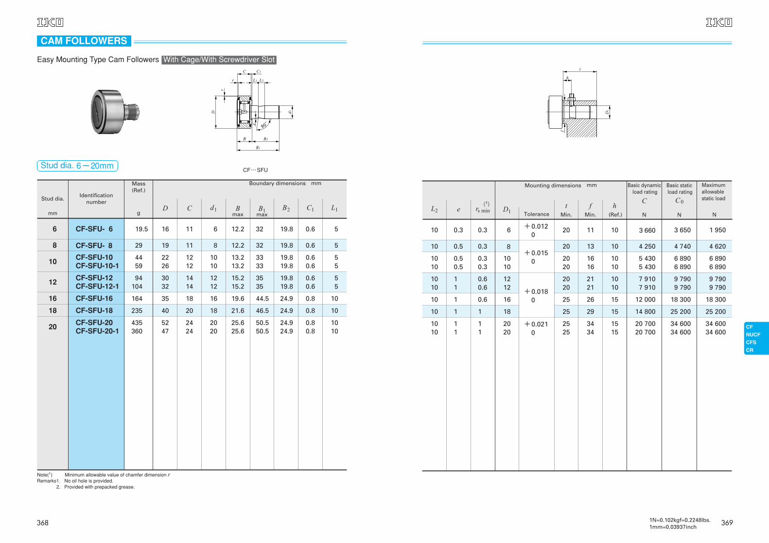
10 0.5 0.3 8+0.015
0
20 13 10 4 250 4 740 4 620
10 1 1 18 25 29 15 14 800 25 200 25 200
1010
11
0.60.6
1212
+0.0180
2020
2121
1010
7 9107 910
9 7909 790
9 7909 790
(1)
Tolerancet
Min.
fMin.
h(Ref.)
Mounting dimensions mm
10 0.3 0.3 6 +0.0120
20 11 10 3 660 3 650 1 950
10 1 0.6 16 25 26 15 12 000 18 300 18 300
1010
11
11
2020
+0.0210
2525
3434
1515
20 70020 700
34 60034 600
34 60034 600
1010
0.50.5
0.30.3
1010
2020
1616
1010
5 4305 430
6 8906 890
6 8906 890
D1L2 e rs min
Basic dynamicload rating
C
N
Basic staticload rating
C0
N
Maximumallowablestatic load
N
3691N=0.102kgf=0.2248lbs.1mm=0.03937inch
29
235
94104
19 11 8 12.2 32 19.8 0.6 5
40 20 18 21.6 46.5 24.9 0.8 10
3032
1414
1212
15.215.2
3535
19.819.8
0.60.6
55
Stud dia.
mm
Identification number
Mass (Ref.)
g
Boundary dimensions mm
6 CF-SFU- 6 1619.5 11 6 12.2 32 19.8 0.6 5
8 CF-SFU- 8
16 CF-SFU-16 35164 18 16 19.6 44.5 24.9 0.8 10
18 CF-SFU-18
20 CF-SFU-20CF-SFU-20-1
5247
435360
2424
2020
25.625.6
50.550.5
24.924.9
0.80.8
1010
10 CF-SFU-10CF-SFU-10-1
2226
4459
1212
1010
13.213.2
3333
19.819.8
0.60.6
55
12 CF-SFU-12CF-SFU-12-1
CF…SFU
Note(1) Minimum allowable value of chamfer dimension rRemarks1. No oil hole is provided.Remarks2. Provided with prepacked grease.
L1B2 C1Bmax
B1max
D C d1
CAM FOLLOWERS
Easy Mounting Type Cam Followers With Cage/With Screwdriver Slot
Stud dia. 6-20mm
368
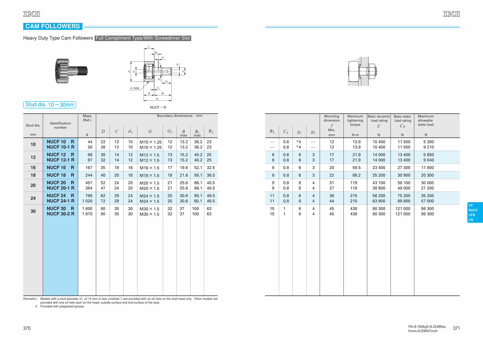
8697
244
7891 020
3032
1414
1212
M12×1.5M12×1.5
1313
15.215.2
40.240.2
2525
40 20 18 M18×1.5 19 21.6 58.1 36.5
6272
2929
2424
M24×1.5M24×1.5
2525
30.630.6
80.180.1
49.549.5
Stud dia.
mm
Identification number
Mass (Ref.)
g
Boundary dimensions mm
10 NUCF 10 RNUCF 10-1 R
4458
2226
1212
1010
M10×1.25M10×1.25
1212
13.213.2
36.236.2
2323
12 NUCF 12 RNUCF 12-1 R
16 NUCF 16 R 167 35 18 16 M16×1.5 17 19.6 52.1 32.5
18 NUCF 18 R
20 NUCF 20 RNUCF 20-1 R
457384
5247
2424
2020
M20×1.5M20×1.5
2121
25.625.6
66.166.1
40.540.5
24 NUCF 24 RNUCF 24-1 R
30 NUCF 30 RNUCF 30-2 R
1 6001 970
8090
3535
3030
M30×1.5M30×1.5
3232
3737
100100
6363
NUCF…R
Remarks1. Models with a stud diameter d1 of 10 mm or less (marked *) are provided with an oil hole on the stud head only. Other models areprovided with one oil hole each on the head, outside surface and end surface of the stud.
Remarks2. Provided with prepacked grease.
G B2G1 Bmax
B1max
D C d1
CAM FOLLOWERS
Heavy Duty Type Cam Followers Full Compliment Type/With Screwdriver Slot
Stud dia. 10-30mm
370
66
0.60.6
66
33
1717
21.921.9
14 00014 000
13 40013 400
5 6509 040
8 0.8 6 3 22 86.2 25 200 30 900 20 300
1111
0.80.8
88
44
3844
215215
58 20063 900
75 30088 800
35 20057 000
──
0.60.6
*4*4
──
1212
13.813.8
10 40010 400
11 50011 500
5 3009 210
8 0.8 6 3 20 58.5 23 400 27 300 11 800
99
0.80.8
88
44
3127
119119
43 10038 900
58 10049 000
30 00027 200
1515
11
88
44
4545
438438
90 30090 300
121 000121 000
98 30098 300
Mountingdimension
fMin.mm
Maximumtightening
torque
N-mg1 g2B3 C1
Basic dynamicload rating
C
N
Basic staticload rating
C0
N
Maximumallowablestatic load
N
3711N=0.102kgf=0.2248lbs.1mm=0.03937inch
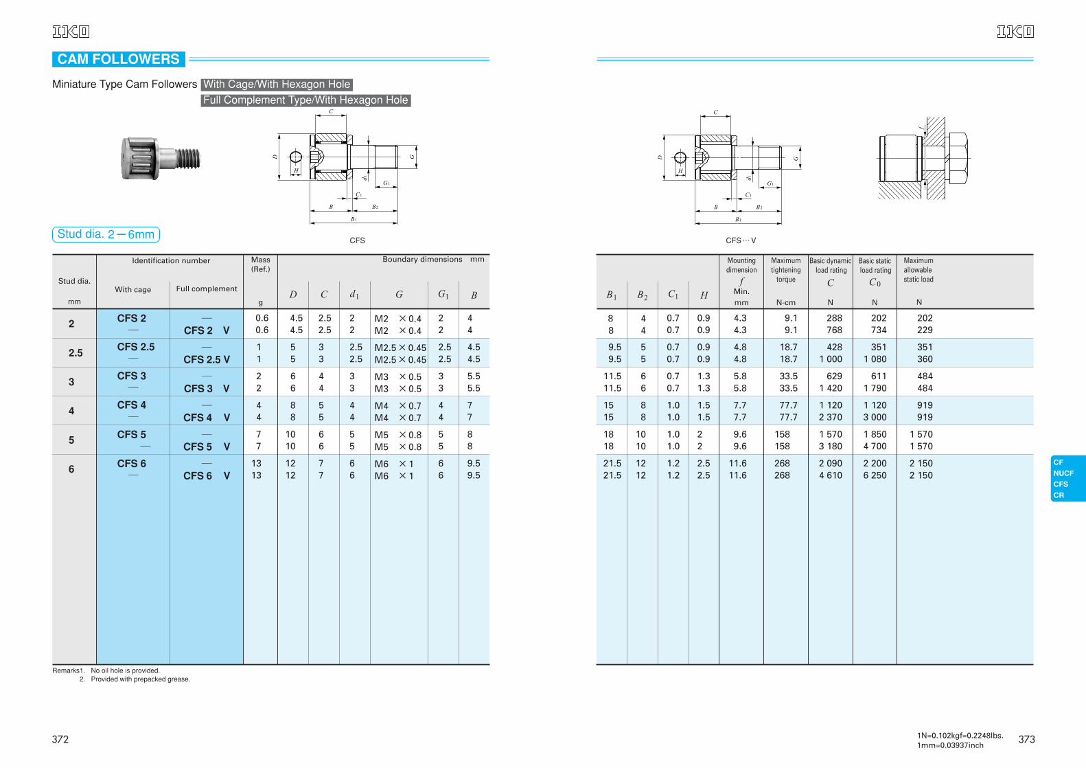
44
88
55
44
M4 ×0.7M4 ×0.7
44
77
22
66
44
33
M3 ×0.5M3 ×0.5
33
77
1010
66
55
M5 ×0.8M5 ×0.8
55
5.55.5
88
Stud dia.
mm
Identification number Mass (Ref.)
g
Boundary dimensions mm
With cage
2.5 ─CFS 2.5 V
CFS 2.5─
11
55
33
2.52.5
M2.5×0.45M2.5×0.45
Full complement
2.52.5
3 ─CFS 3 V
CFS 3─
4 ─CFS 4 V
CFS 4─
5 ─CFS 5 V
CFS 5─
6 ─CFS 6 V
CFS 6─
1313
1212
77
66
M6 ×1M6 ×1
66
B
4.54.5
9.59.5
CFS
Full Complement Type/With Hexagon Hole
Remarks1. No oil hole is provided.Remarks2. Provided with prepacked grease.
2 CFS 2─
─CFS 2 V
0.60.6
4.54.5
2.52.5
22
M2 ×0.4M2 ×0.4
22
44
G G1D C d1
CAM FOLLOWERS
Miniature Type Cam Followers With Cage/With Hexagon Hole
Stud dia. 2-6mm
372
11.511.5
66
0.70.7
1.31.3
5.85.8
33.533.5
6291 420
6111 790
484484
1818
1010
1.01.0
22
9.69.6
158158
1 5703 180
1 8504 700
1 5701 570
Basic dynamicload rating
C
N
Basic staticload rating
C0
N
Maximumallowablestatic load
NB1 HC1
9.59.5
55
0.70.7
0.90.9
4.84.8
18.718.7
4281 000
3511 080
351360
1515
88
1.01.0
1.51.5
7.77.7
77.777.7
1 1202 370
1 1203 000
919919
21.521.5
1212
1.21.2
2.52.5
11.611.6
268268
2 0904 610
2 2006 250
2 1502 150
B2
Mountingdimension
fMin.mm
Maximumtightening
torque
N-cm
CFS…V
88
44
0.70.7
0.90.9
4.34.3
9.19.1
288768
202734
202229
3731N=0.102kgf=0.2248lbs.1mm=0.03937inch
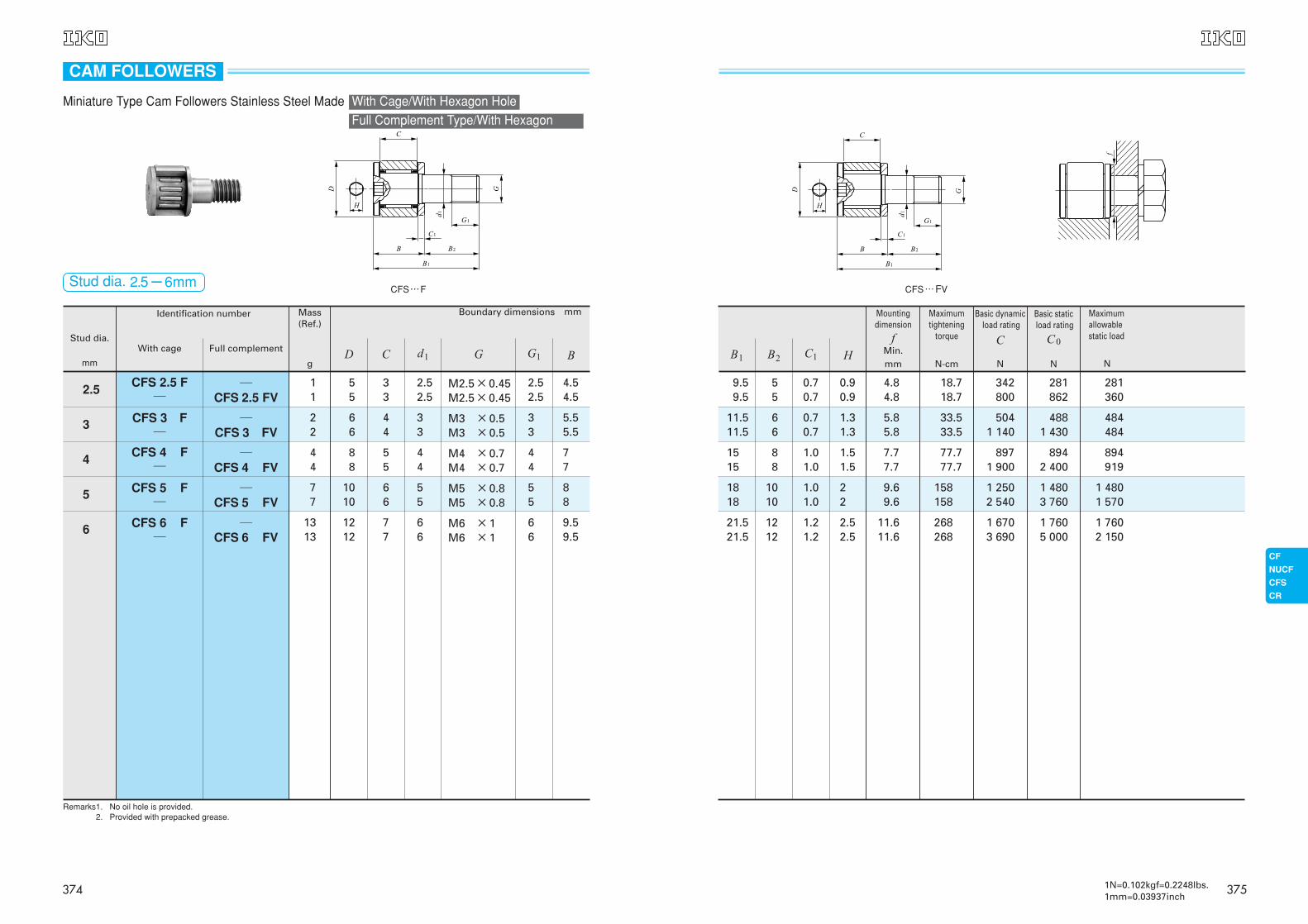
22
66
44
33
M3 ×0.5M3 ×0.5
33
77
1010
66
55
M5 ×0.8M5 ×0.8
55
5.55.5
88
Stud dia.
mm
Identification number Mass (Ref.)
g
Boundary dimensions mm
With cage
2.5 ─CFS 2.5 FV
CFS 2.5 F─
11
55
33
2.52.5
M2.5×0.45M2.5×0.45
Full complement
2.52.5
3 ─CFS 3 FV
CFS 3 F─
4 ─CFS 4 FV
CFS 4 F─
44
88
55
44
M4 ×0.7M4 ×0.7
44
5 ─CFS 5 FV
CFS 5 F─
6 ─CFS 6 FV
CFS 6 F─
1313
1212
77
66
M6 ×1M6 ×1
66
4.54.5
77
9.59.5
CFS…F
Remarks1. No oil hole is provided.Remarks2. Provided with prepacked grease.
BG G1D C d1
CAM FOLLOWERS
Full Complement Type/With Hexagon
Miniature Type Cam Followers Stainless Steel Made With Cage/With Hexagon Hole
Stud dia. 2.5-6mm
374
11.511.5
66
0.70.7
1.31.3
5.85.8
33.533.5
5041 140
4881 430
484484
1818
1010
1.01.0
22
9.69.6
158158
1 2502 540
1 4803 760
1 4801 570
9.59.5
55
0.70.7
0.90.9
4.84.8
18.718.7
342800
281862
281360
1515
88
1.01.0
1.51.5
7.77.7
77.777.7
8971 900
8942 400
894919
21.521.5
1212
1.21.2
2.52.5
11.611.6
268268
1 6703 690
1 7605 000
1 7602 150
CFS…FV
Basic dynamicload rating
C
N
Basic staticload rating
C0
N
Maximumallowablestatic load
NB1 HC1B2
Mountingdimension
fMin.mm
Maximumtightening
torque
N-cm
3751N=0.102kgf=0.2248lbs.1mm=0.03937inch
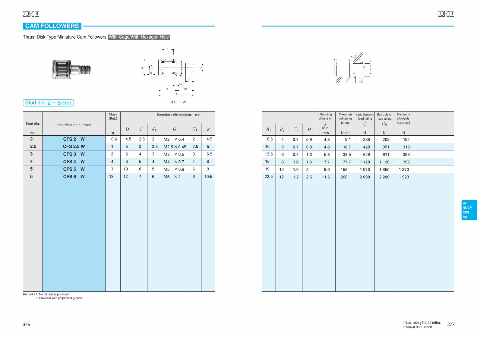
8.5
10
12.5
16
19
22.5
4 0.7 0.9 4.3 9.1 288 202 194
5 0.7 0.9 4.8 18.7 428 351 313
6 0.7 1.3 5.8 33.5 629 611 399
8 1.0 1.5 7.7 77.7 1 120 1 120 785
10 1.0 2 9.6 158 1 570 1 850 1 370
12 1.2 2.5 11.6 268 2 090 2 200 1 920
CFS…FV
Basic staticload rating
C0
NB1 HC1B2
Mountingdimension
fMin.mm
Maximumtightening
torque
N-cm
Maximumallowablestatic load
N
f
Basic dynamicload rating
C
N
3771N=0.102kgf=0.2248lbs.1mm=0.03937inch
Stud dia.
mm
Identification number
Mass(Ref.)
g
Boundary dimensions mm
2 CFS 2 W 00.6 04.5 02.5 2 M2 ×0.4 2 4.5
2.5 CFS 2.5 W 1 5 3 2.5 M2.5×0.45 2.5 5
3 CFS 3 W 2 6 4 3 M3 ×0.5 3 6.5
4 CFS 4 W 4 8 5 4 M4 ×0.7 4 8
5 CFS 5 W 7 10 6 5 M5 ×0.8 5 9
6 CFS 6 W 13 12 7 6 M6 ×1 6 10.5
CFS…W
Remarks 1. No oil hole is provided.Remarks 2. Provided with prepacked grease.
BG G1D C d1
Thrust Disk Type Miniature Cam Followers
CFS…FW
B1
B2
C1
G1
d1
GD
C
H
B
CAM FOLLOWERS
With Cage/With Hexagon Hole
Stud dia. 2-6mm
376
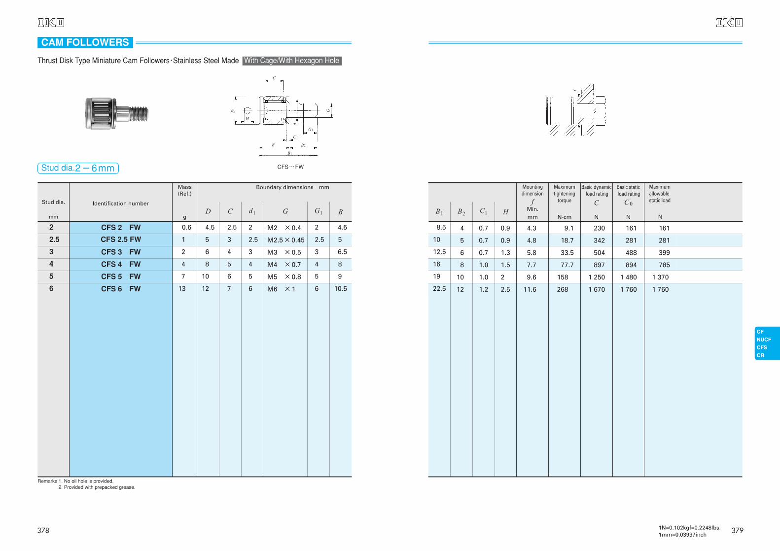
CFS…FW
B1
B2
C1
G1
d1
GD
C
H
B
Stud dia.
mm
Identification number
Mass(Ref.)
g
Boundary dimensions mm
2 CFS 2 FW 00.6 04.5 02.5 2 M2 ×0.4 2 14.5
2.5 CFS 2.5 FW 1 5 3 2.5 M2.5×0.45 2.5 5
3 CFS 3 FW 2 6 4 3 M3 ×0.5 3 16.5
4 CFS 4 FW 4 8 5 4 M4 ×0.7 4 8
5 CFS 5 FW 7 10 6 5 M5 ×0.8 5 9
6 CFS 6 FW 13 12 7 6 M6 ×1 6 10.5
CFS…W
Remarks 1. No oil hole is provided.Remarks 2. Provided with prepacked grease.
Stud dia.2-6mm
BG G1D C d1
Thrust Disk Type Miniature Cam Followers・Stainless Steel Made With Cage/With Hexagon Hole
CAM FOLLOWERS
378
18.5
10
12.5
16
19
22.5
4 0.7 0.9 4.3 9.1 230 161 161
5 0.7 0.9 4.8 18.7 342 281 281
6 0.7 1.3 5.8 33.5 504 488 399
8 1.0 1.5 7.7 77.7 897 894 785
10 1.0 2 9.6 158 1 250 1 480 1 370
12 1.2 2.5 11.6 268 1 670 1 760 1 760
CFS…FV
f
Basic dynamicload rating
C
N
Basic staticload rating
C0
N
Maximumallowablestatic load
NB1 HC1B2
Mountingdimension
fMin.mm
Maximumtightening
torque
N-cm
3791N=0.102kgf=0.2248lbs.1mm=0.03937inch
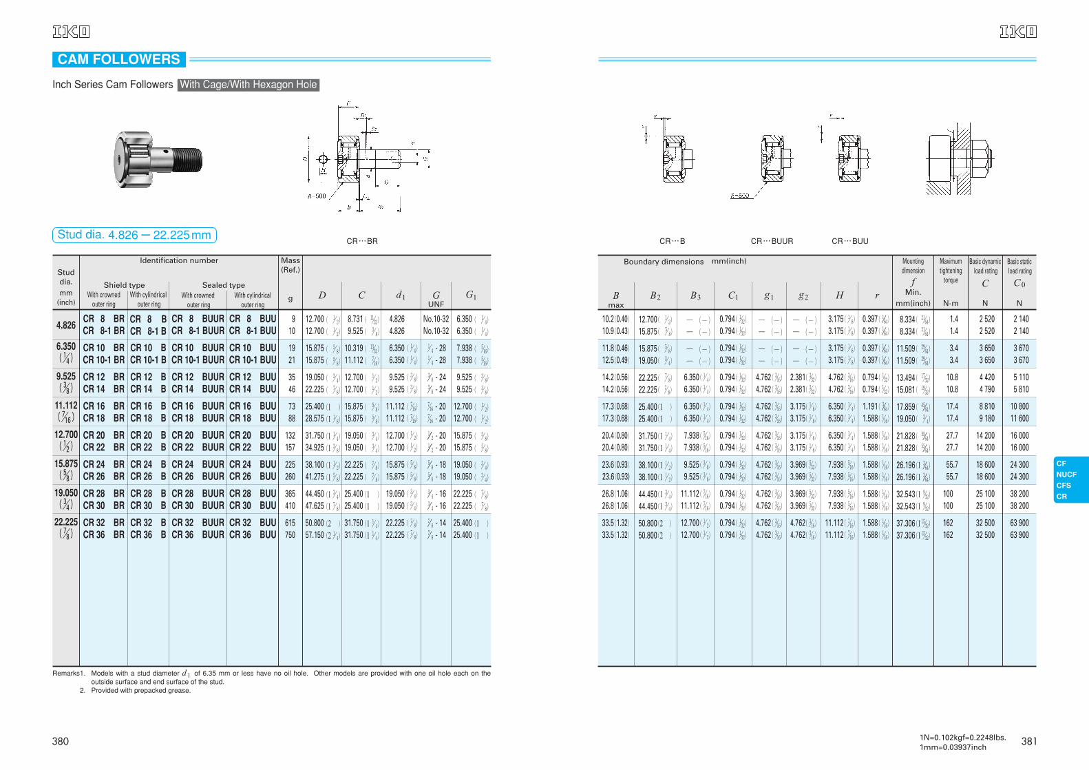
CR…BR
Studdia.mm
(inch)
Mass(Ref.)
g
Identification number
4.826
With crowned outer ring
With cylindricalouter ring
With crownedouter ring
With cylindrical outer ring
6.350( !/4)
9.525( #/8)
11.112( &/16)
12.700( !/2)
15.875( %/8)
19.050( #/4)
22.225( &/8)
Shield type Sealed type
Remarks1. Models with a stud diameter d1 of 6.35 mm or less have no oil hole. Other models are provided with one oil hole each on theoutside surface and end surface of the stud.
Remarks2. Provided with prepacked grease.
CR 8 BRCR 8-1 BR
CR 8 BCR 8-1 B
CR 8 BUURCR 8-1 BUUR
CR 8 BUUCR 8-1 BUU
CR 10 BRCR 10-1 BR
CR 10 BCR 10-1 B
CR 10 BUURCR 10-1 BUUR
CR 10 BUUCR 10-1 BUU
CR 12 BRCR 14 BR
CR 12 BCR 14 B
CR 12 BUURCR 14 BUUR
CR 12 BUUCR 14 BUU
CR 16 BRCR 18 BR
CR 16 BCR 18 B
CR 16 BUURCR 18 BUUR
CR 16 BUUCR 18 BUU
CR 20 BRCR 22 BR
CR 20 BCR 22 B
CR 20 BUURCR 22 BUUR
CR 20 BUUCR 22 BUU
CR 24 BRCR 26 BR
CR 24 BCR 26 B
CR 24 BUURCR 26 BUUR
CR 24 BUUCR 26 BUU
CR 28 BRCR 30 BR
CR 28 BCR 30 B
CR 28 BUURCR 30 BUUR
CR 28 BUUCR 30 BUU
CR 32 BRCR 36 BR
CR 32 BCR 36 B
CR 32 BUURCR 36 BUUR
CR 32 BUUCR 36 BUU
8.7319.525
4.8264.826
No.10-32No.10-32
6.3506.350
910
10.31911.112
6.3506.350
!/ 4 - 28!/ 4 - 28
7.9387.938
1921
12.70012.700
9.5259.525
#// 8 - 24#// 8 - 24
9.5259.525
3546
15.87515.875
11.11211.112
&/16 - 20&/16 - 20
12.70012.700
7388
19.05019.050
12.70012.700
!/// 2 - 20!/// 2 - 20
15.87515.875
132157
22.22522.225
15.87515.875
%// 8 - 18%// 8 - 18
19.05019.050
225260
25.40025.400
19.05019.050
#// 4 - 16#// 4 - 16
22.22522.225
365410
31.75031.750
22.22522.225
( !/ 4)
( !/ 4)
( #/ 8)
( #/ 8)
( &/16)
( &/16)
( !/ 2)
( !/ 2)
( %/ 8)
( %/ 8)
( #/ 4)
( #/ 4)
( &/ 8)
( &/ 8)
&// 8 - 14&// 8 - 14
25.40025.400
( !/ 4)
( !/ 4)
( %/16)
( %/16)
( #/ 8)
( #/ 8)
( !/ 2)
( !/ 2)
( %/ 8)
( %/ 8)
( #/ 4)
( #/ 4)
( &/ 8)
( &/ 8)
(1 )
(1 )
615750
( !/ 2)
( !/ 2)
( %/ 8)
( %/ 8)
( #/ 4)
( &/ 8)
(1 )
(1 !/ 8)
(1 !/ 4)
(1 #/ 8)
(1 !/ 2)
(1 %/ 8)
(1 #/ 4)
(1 &/ 8)
(2 )
(2 !/ 4)
12.70012.700
15.87515.875
19.05022.225
25.40028.575
31.75034.925
38.10041.275
44.45047.625
50.80057.150
( !!/32)
( #/ 8)
( !#/32)
( &/16)
( !/ 2)
( !/ 2)
( %/ 8)
( %/ 8)
( #/ 4)
( #/ 4)
( &/ 8)
( &/ 8)
(1 )
(1 )
(1 !/ 4)
(1 !/ 4)
Stud dia. 4.826-22.225mm
GUNF
G1D C d1
CAM FOLLOWERS
Inch Series Cam Followers With Cage/With Hexagon Hole
380
CR…B
2 1402 140
3 6703 670
5 1105 810
10 80011 600
16 00016 000
24 30024 300
38 20038 200
63 90063 900
Boundary dimensions mm(inch)
Bmax
B2 B3 C1 g1 g2 H r
12.700( !/ 2)
15.875( %/ 8)
0.794( !/32)
0.794( !/32)
10.2(0.40)10.9(0.43)
0.397( !//64)
0.397( !//64)8.334( @!/64)
8.334( @!/64)
1.41.4
2 5202 520
─ (─)─ (─)
─ (─)─ (─)
─ (─)─ (─)
15.875( %/ 8)
19.050( #/ 4)
0.794( !/32)
0.794( !/32)
11.8(0.46)12.5(0.49)
0.397( !//64)
0.397( !//64)11.509( @(/64)
11.509( @(/64)
3.43.4
3 6503 650
─ (─)─ (─)
─ (─)─ (─)
─ (─)─ (─)
22.225( &/ 8)
22.225( &/ 8)
0.794( !/32)
0.794( !/32)
14.2(0.56)14.2(0.56)
0.794( !/32)
0.794( !/32)13.494( !&/32)
15.081( !(/32)
10.810.8
4 4204 790
2.381( #/32)
2.381( #/32)
4.762( #/16)
4.762( #/16)
6.350( !/ 4)
6.350( !/ 4)
25.400(1 )
25.400(1 )
0.794( !/32)
0.794( !/32)
17.3(0.68)17.3(0.68)
1.191( #//64)
1.588( !/16)17.859( $%//64)
19.050( #/ 4)
17.417.4
8 8109 180
3.175( !/ 8)
3.175( !/ 8)
4.762( #/16)
4.762( #/16)
6.350( !/ 4)
6.350( !/ 4)
31.750(1 !/ 4)
31.750(1 !/ 4)
0.794( !/32)
0.794( !/32)
20.4(0.80)20.4(0.80)
1.588( !/16)
1.588( !/16)
1.588( !/16)
1.588( !/16)
21.828( %%//64)
21.828( %%//64)
27.727.7
14 20014 200
3.175( !/ 8)
3.175( !/ 8)
4.762( #/16)
4.762( #/16)
7.938( %/16)
7.938( %/16)
38.100(1 !/ 2)
38.100(1 !/ 2)
0.794( !/32)
0.794( !/32)
23.6(0.93)23.6(0.93)
26.196(1 #//64)
26.196(1 #//64)
55.755.7
18 60018 600
3.969( %/32)
3.969( %/32)
4.762( #/16)
4.762( #/16)
9.525( #/ 8)
9.525( #/ 8)
44.450(1 #/ 4)
44.450(1 #/ 4)
0.794( !/32)
0.794( !/32)
26.8(1.06)26.8(1.06)
1.588( !/16)
1.588( !/16)32.543(1 (/32)
32.543(1 (/32)
100100
25 10025 100
3.969( %/32)
3.969( %/32)
4.762( #/16)
4.762( #/16)
11.112( &/16)
11.112( &/16)
50.800(2 )
50.800(2 )
0.794( !/32)
0.794( !/32)
33.5(1.32)33.5(1.32)
1.588( !/16)
1.588( !/16)37.306(1 !%/32)
37.306(1 !%/32)
162162
32 50032 500
4.762( #/16)
4.762( #/16)
4.762( #/16)
4.762( #/16)
3.175( !/ 8)
3.175( !/ 8)
3.175( !/ 8)
3.175( !/ 8)
4.762( #/16)
4.762( #/16)
6.350( !/ 4)
6.350( !/ 4)
6.350( !/ 4)
6.350( !/ 4)
7.938( %/16)
7.938( %/16)
7.938( %/16)
7.938( %/16)
11.112( &/16)
11.112( &/16)
12.700( !/ 2)
12.700( !/ 2)
CR…BUU
Basic dynamicload rating
C
N
Basic staticload rating
C0
N
Mountingdimension
fMin.
mm(inch)
Maximumtightening
torque
N-m
CR…BUUR
3811N=0.102kgf=0.2248lbs.1mm=0.03937inch
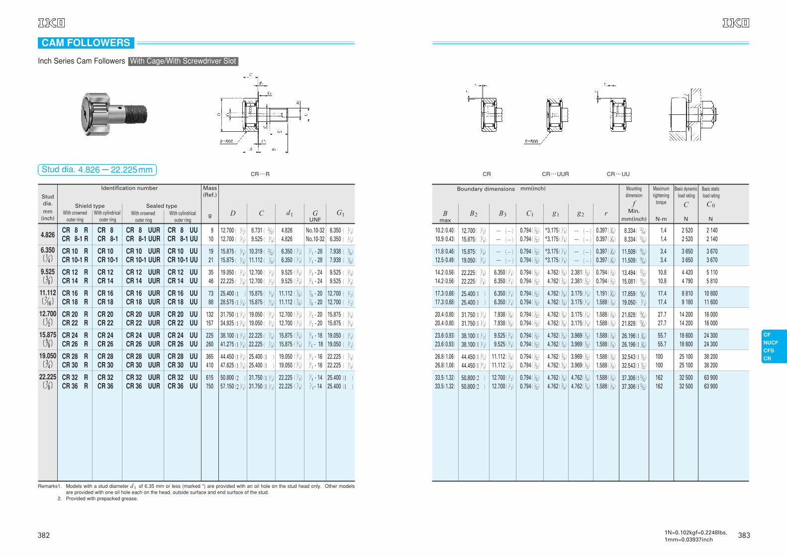
CR…R
Mass(Ref.)
g
4.8268.7319.525
4.8264.826
No.10-32No.10-32
6.3506.350
910
6.350( !/4)
10.31911.112
6.3506.350
!/ 4 - 28!/ 4 - 28
7.9387.938
1921
9.525( #/8)
12.70012.700
9.5259.525
#/ 8 - 24#/ 8 - 24
9.5259.525
3546
11.112( &/16)
15.87515.875
11.11211.112
&/16 - 20&/16 - 20
12.70012.700
7388
12.700( !/2)
19.05019.050
12.70012.700
!/ 2 - 20!/ 2 - 20
15.87515.875
132157
15.875( %/8)
22.22522.225
15.87515.875
%/ 8 - 18%/ 8 - 18
19.05019.050
225260
19.050( #/4)
25.40025.400
19.05019.050
#/ 4 - 16#/ 4 - 16
22.22522.225
365410
22.225( &/8)
31.75031.750
22.22522.225
( !/ 4)
( !/ 4)
( #/ 8)
( #/ 8)
( &/16)
( &/16)
( !/ 2)
( !/ 2)
( %/ 8)
( %/ 8)
( #/ 4)
( #/ 4)
( &/ 8)
( &/ 8)
&/ 8 - 14&/ 8 - 14
25.40025.400
( !/ 4)
( !/ 4)
( %/16)
( %/16)
( #/ 8)
( #/ 8)
( !/ 2)
( !/ 2)
( %/ 8)
( %/ 8)
( #/ 4)
( #/ 4)
( &/ 8)
( &/ 8)
(1 )
(1 )
615750
( !/ 2)
( !/ 2)
( %/ 8)
( %/ 8)
( #/ 4)
( &/ 8)
(1 )
(1 !/ 8)
(1 !/ 4)
(1 #/ 8)
(1 !/ 2)
(1 %/ 8)
(1 #/ 4)
(1 &/ 8)
(2 )
(2 !/ 4)
12.70012.700
15.87515.875
19.05022.225
25.40028.575
31.75034.925
38.10041.275
44.45047.625
50.80057.150
( !!/32)
( #/ 8)
( !#/32)
( &/16)
( !/ 2)
( !/ 2)
( %/ 8)
( %/ 8)
( #/ 4)
( #/ 4)
( &/ 8)
( &/ 8)
(1 )
(1 )
(1 !/ 4)
(1 !/ 4)
Remarks1. Models with a stud diameter d1 of 6.35 mm or less (marked *) are provided with an oil hole on the stud head only. Other modelsare provided with one oil hole each on the head, outside surface and end surface of the stud.
Remarks2. Provided with prepacked grease.
Studdia.mm
(inch)
Identification number
With crowned outer ring
With cylindricalouter ring
With crownedouter ring
With cylindrical outer ring
Shield type Sealed type
CR 8 RCR 8-1 R
CR 8CR 8-1
CR 8 UURCR 8-1 UUR
CR 8 UUCR 8-1 UU
CR 10 RCR 10-1 R
CR 10CR 10-1
CR 10 UURCR 10-1 UUR
CR 10 UUCR 10-1 UU
CR 12 RCR 14 R
CR 12CR 14
CR 12 UURCR 14 UUR
CR 12 UUCR 14 UU
CR 16 RCR 18 R
CR 16CR 18
CR 16 UURCR 18 UUR
CR 16 UUCR 18 UU
CR 20 RCR 22 R
CR 20CR 22
CR 20 UURCR 22 UUR
CR 20 UUCR 22 UU
CR 24 RCR 26 R
CR 24CR 26
CR 24 UURCR 26 UUR
CR 24 UUCR 26 UU
CR 28 RCR 30 R
CR 28CR 30
CR 28 UURCR 30 UUR
CR 28 UUCR 30 UU
CR 32 RCR 36 R
CR 32CR 36
CR 32 UURCR 36 UUR
CR 32 UUCR 36 UU
GUNF
G1D C d1
CAM FOLLOWERS
Inch Series Cam Followers With Cage/With Screwdriver Slot
Stud dia. 4.826-22.225mm
382
CR…UUCR
2 1402 140
3 6703 670
5 1105 810
10 80011 600
16 00016 000
24 30024 300
38 20038 200
63 90063 900
Boundary dimensions mm(inch)
12.700( !/ 2)
15.875( %/ 8)
0.794( !/32)
0.794( !/32)
10.2(0.40)10.9(0.43)
0.397( !//64)
0.397( !//64)8.334( @!/64)
8.334( @!/64)
1.41.4
2 5202 520
─ (─)─ (─)
*3.175( !/ 8)
*3.175( !/ 8)─ (─)─ (─)
15.875( %/ 8)
19.050( #/ 4)
0.794( !/32)
0.794( !/32)
11.8(0.46)12.5(0.49)
0.397( !//64)
0.397( !//64)11.509( @(/64)
11.509( @(/64)
3.43.4
3 6503 650
─ (─)─ (─)
*3.175( !/ 8)
*3.175( !/ 8)─ (─)─ (─)
22.225( &/ 8)
22.225( &/ 8)
0.794( !/32)
0.794( !/32)
14.2(0.56)14.2(0.56)
0.794( !/32)
0.794( !/32)13.494( !&/32)
15.081( !(/32)
10.810.8
4 4204 790
2.381( #/32)
2.381( #/32)
4.762( #/16)
4.762( #/16)
6.350( !/ 4)
6.350( !/ 4)
25.400(1 )
25.400(1 )
0.794( !/32)
0.794( !/32)
17.3(0.68)17.3(0.68)
1.191( #//64)
1.588( !/16)17.859( $%//64)
19.050( #/ 4)
17.417.4
8 8109 180
3.175( !/ 8)
3.175( !/ 8)
4.762( #/16)
4.762( #/16)
6.350( !/ 4)
6.350( !/ 4)
31.750(1 !/ 4)
31.750(1 !/ 4)
0.794( !/32)
0.794( !/32)
20.4(0.80)20.4(0.80)
1.588( !/16)
1.588( !/16)21.828( %%//64)
21.828( %%//64)
27.727.7
14 20014 200
3.175( !/ 8)
3.175( !/ 8)
4.762( #/16)
4.762( #/16)
7.938( %/16)
7.938( %/16)
38.100(1 !/ 2)
38.100(1 !/ 2)
0.794( !/32)
0.794( !/32)
23.6(0.93)23.6(0.93)
1.588( !/16)
1.588( !/16)26.196(1 #//64)
26.196(1 #//64)
55.755.7
18 60018 600
3.969( %/32)
3.969( %/32)
4.762( #/16)
4.762( #/16)
9.525( #/ 8)
9.525( #/ 8)
44.450(1 #/ 4)
44.450(1 #/ 4)
0.794( !/32)
0.794( !/32)
26.8(1.06)26.8(1.06)
1.588( !/16)
1.588( !/16)32.543(1 (/32)
32.543(1 (/32)
100100
25 10025 100
3.969( %/32)
3.969( %/32)
4.762( #/16)
4.762( #/16)
11.112( &/16)
11.112( &/16)
50.800(2 )
50.800(2 )
0.794( !/32)
0.794( !/32)
33.5(1.32)33.5(1.32)
1.588( !/16)
1.588( !/16)37.306(1 !%/32)
37.306(1 !%/32)
162162
32 50032 500
4.762( #/16)
4.762( #/16)
4.762( #/16)
4.762( #/16)
12.700( !/ 2)
12.700( !/ 2)
CR…UUR
Bmax
B2 B3 C1 g1 g2 r
Basic dynamicload rating
C
N
Basic staticload rating
C0
N
Mountingdimension
fMin.
mm(inch)
Maximumtightening
torque
N-m
3831N=0.102kgf=0.2248lbs.1mm=0.03937inch
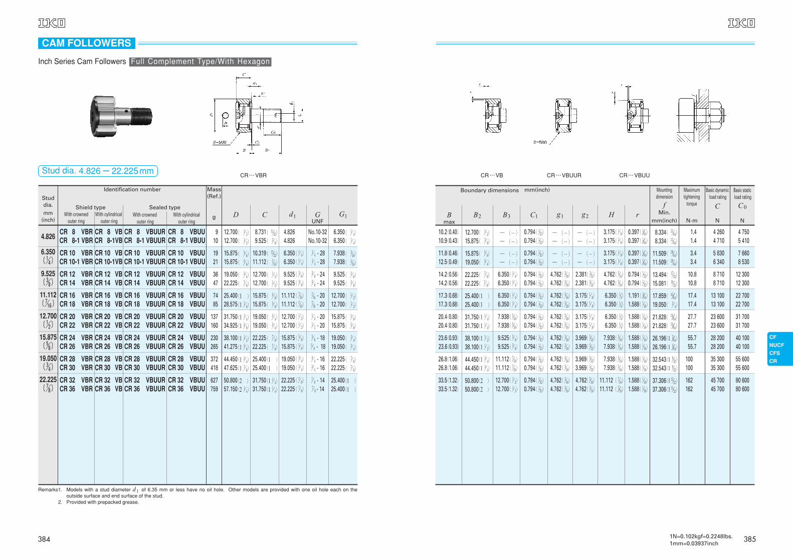
4 7505 410
7 6608 530
12 30012 300
22 70022 700
31 70031 700
40 10040 100
55 60055 600
80 60080 600
Boundary dimensions mm(inch)
12.700( !/ 2)
15.875( %/ 8)
0.794( !/32)
0.794( !/32)
10.2(0.40)10.9(0.43)
0.397( !//64)
0.397( !//64)8.334( @!/64)
8.334( @!/64)
1.41.4
4 2604 710
─ (─)─ (─)
─ (─)─ (─)
─ (─)─ (─)
15.875( %/ 8)
19.050( #/ 4)
0.794( !/32)
0.794( !/32)
11.8(0.46)12.5(0.49)
0.397( !//64)
0.397( !//64)11.509( @(/64)
11.509( @(/64)
3.43.4
5 8306 340
─ (─)─ (─)
─ (─)─ (─)
─ (─)─ (─)
22.225( &/ 8)
22.225( &/ 8)
0.794( !/32)
0.794( !/32)
14.2(0.56)14.2(0.56)
0.794( !/32)
0.794( !/32)13.494( !&/32)
15.081( !(/32)
10.810.8
8 7108 710
2.381( #/32)
2.381( #/32)
4.762( #/16)
4.762( #/16)
6.350( !/ 4)
6.350( !/ 4)
25.400(1 )
25.400(1 )
0.794( !/32)
0.794( !/32)
17.3(0.68)17.3(0.68)
1.191( #//64)
1.588( !/16)17.859( $%//64)
19.050( #/ 4)
17.417.4
13 10013 100
3.175( !/ 8)
3.175( !/ 8)
4.762( #/16)
4.762( #/16)
6.350( !/ 4)
6.350( !/ 4)
31.750(1 !/ 4)
31.750(1 !/ 4)
0.794( !/32)
0.794( !/32)
20.4(0.80)20.4(0.80)
1.588( !/16)
1.588( !/16)21.828( %%//64)
21.828( %%//64)
27.727.7
23 60023 600
3.175( !/ 8)
3.175( !/ 8)
4.762( #/16)
4.762( #/16)
7.938( %/16)
7.938( %/16)
38.100(1 !/ 2)
38.100(1 !/ 2)
0.794( !/32)
0.794( !/32)
23.6(0.93)23.6(0.93)
1.588( !/16)
1.588( !/16)26.196(1 #//64)
26.196(1 #//64)
55.755.7
28 20028 200
3.969( %/32)
3.969( %/32)
4.762( #/16)
4.762( #/16)
9.525( #/ 8)
9.525( #/ 8)
44.450(1 #/ 4)
44.450(1 #/ 4)
0.794( !/32)
0.794( !/32)
26.8(1.06)26.8(1.06)
1.588( !/16)
1.588( !/16)32.543(1 (/32)
32.543(1 (/32)
100100
35 30035 300
3.969( %/32)
3.969( %/32)
4.762( #/16)
4.762( #/16)
11.112( &/16)
11.112( &/16)
50.800(2 )
50.800(2 )
0.794( !/32)
0.794( !/32)
33.5(1.32)33.5(1.32)
1.588( !/16)
1.588( !/16)37.306(1 !%/32)
37.306(1 !%/32)
162162
45 70045 700
4.762( #/16)
4.762( #/16)
4.762( #/16)
4.762( #/16)
3.175( !/ 8)
3.175( !/ 8)
3.175( !/ 8)
3.175( !/ 8)
4.762( #/16)
4.762( #/16)
6.350( !/4)
6.350( !/4)
6.350( !/4)
6.350( !/4)
7.938( %/16)
7.938( %/16)
7.938( %/16)
7.938( %/16)
11.112( &/16)
11.112( &//16)
12.700( !/ 2)
12.700( !/ 2)
Bmax
B2 B3 C1 g1 g2 H r
Basic dynamicload rating
C
N
Basic staticload rating
C0
N
Mountingdimension
fMin.
mm(inch)
Maximumtightening
torque
N-m
CR…VB CR…VBUUCR…VBUUR
3851N=0.102kgf=0.2248lbs.1mm=0.03937inch
Mass(Ref.)
g
4.8268.7319.525
4.8264.826
No.10-32No.10-32
6.3506.350
910
6.350( !/4)
10.31911.112
6.3506.350
!/ 4 - 28!/ 4 - 28
7.9387.938
1921
9.525( #/8)
12.70012.700
9.5259.525
#/ 8 - 24#/ 8 - 24
9.5259.525
3647
11.112( &/16)
15.87515.875
11.11211.112
&/16 - 20&/16 - 20
12.70012.700
7485
12.700( !/2)
19.05019.050
12.70012.700
!/ 2 - 20!/ 2 - 20
15.87515.875
137160
15.875( %/8)
22.22522.225
15.87515.875
%/ 8 - 18%/ 8 - 18
19.05019.050
230265
19.050( #/4)
25.40025.400
19.05019.050
#/ 4 - 16#/ 4 - 16
22.22522.225
372418
22.225( &/8)
31.75031.750
22.22522.225
( !/ 4)
( !/ 4)
( #/ 8)
( #/ 8)
( &/16)
( &/16)
( !/ 2)
( !/ 2)
( %/ 8)
( %/ 8)
( #/ 4)
( #/ 4)
( &/ 8)
( &/ 8)
&/ 8 - 14&/ 8 - 14
25.40025.400
( !/ 4)
( !/ 4)
( %/16)
( %/16)
( #/ 8)
( #/ 8)
( !/ 2)
( !/ 2)
( %/ 8)
( %/ 8)
( #/ 4)
( #/ 4)
( &/ 8)
( &/ 8)
(1 )
(1 )
627759
( !/ 2)
( !/ 2)
( %/ 8)
( %/ 8)
( #/ 4)
( &/ 8)
(1 )
(1 !/ 8)
(1 !/ 4)
(1 #/ 8)
(1 !/ 2)
(1 %/ 8)
(1 #/ 4)
(1 &/ 8)
(2 )
(2 !/ 4)
12.70012.700
15.87515.875
19.05022.225
25.40028.575
31.75034.925
38.10041.275
44.45047.625
50.80057.150
( !!/32)
( #/ 8)
( !#/32)
( &/16)
( !/ 2)
( !/ 2)
( %/ 8)
( %/ 8)
( #/ 4)
( #/ 4)
( &/ 8)
( &/ 8)
(1 )
(1 )
(1 !/ 4)
(1 !/ 4)
Studdia.mm
(inch)
Identification number
With crowned outer ring
With cylindricalouter ring
With crownedouter ring
With cylindrical outer ring
Shield type Sealed type
CR 8 VBRCR 8-1 VBR
CR 8 VBCR 8-1VB
CR 8 VBUURCR 8-1 VBUUR
CR 8 VBUUCR 8-1 VBUU
CR 10 VBRCR 10-1 VBR
CR 10 VBCR 10-1VB
CR 10 VBUURCR 10-1 VBUUR
CR 10 VBUUCR 10-1 VBUU
CR 12 VBRCR 14 VBR
CR 12 VBCR 14 VB
CR 12 VBUURCR 14 VBUUR
CR 12 VBUUCR 14 VBUU
CR 16 VBRCR 18 VBR
CR 16 VBCR 18 VB
CR 16 VBUURCR 18 VBUUR
CR 16 VBUUCR 18 VBUU
CR 20 VBRCR 22 VBR
CR 20 VBCR 22 VB
CR 20 VBUURCR 22 VBUUR
CR 20 VBUUCR 22 VBUU
CR 24 VBRCR 26 VBR
CR 24 VBCR 26 VB
CR 24 VBUURCR 26 VBUUR
CR 24 VBUUCR 26 VBUU
CR 28 VBRCR 30 VBR
CR 28 VBCR 30 VB
CR 28 VBUURCR 30 VBUUR
CR 28 VBUUCR 30 VBUU
CR 32 VBRCR 36 VBR
CR 32 VBCR 36 VB
CR 32 VBUURCR 36 VBUUR
CR 32 VBUUCR 36 VBUU
Remarks1. Models with a stud diameter d1 of 6.35 mm or less have no oil hole. Other models are provided with one oil hole each on theoutside surface and end surface of the stud.
Remarks2. Provided with prepacked grease.
GUNF
G1D C d1
CR…VBR
CAM FOLLOWERS
Inch Series Cam Followers Full Complement Type/With Hexagon
Stud dia. 4.826-22.225mm
384
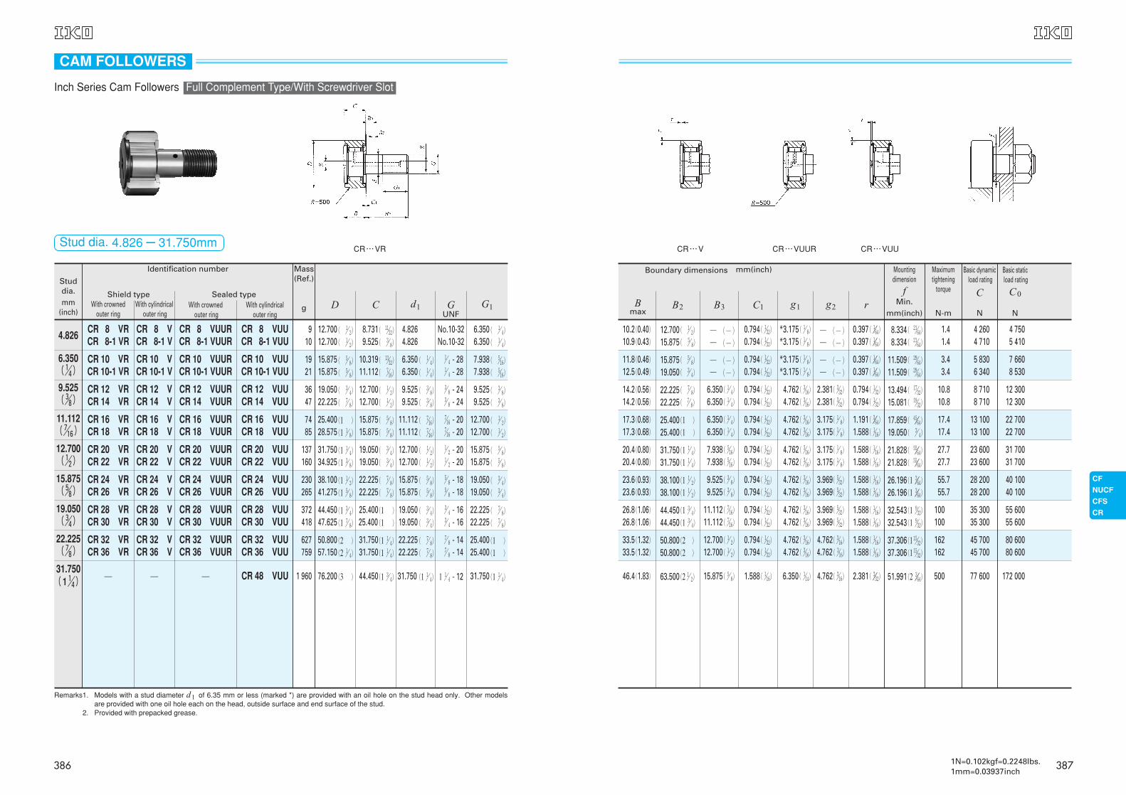
Mass(Ref.)
g
4.8268.7319.525
4.8264.826
No.10-32No.10-32
6.3506.350
910
6.350( !/4)
10.31911.112
6.3506.350
!/ 4 - 28!/ 4 - 28
7.9387.938
1921
9.525( #/8)
12.70012.700
9.5259.525
#/ 8 - 24#/ 8 - 24
9.5259.525
3647
11.112( &/16)
15.87515.875
11.11211.112
&/16 - 20&/16 - 20
12.70012.700
7485
12.700( !/2)
19.05019.050
12.70012.700
!/ 2 - 20!/ 2 - 20
15.87515.875
137160
15.875( %/8)
22.22522.225
15.87515.875
%/ 8 - 18%/ 8 - 18
19.05019.050
230265
19.050( #/4)
25.40025.400
19.05019.050
#/ 4 - 16#/ 4 - 16
22.22522.225
372418
22.225( &/8)
31.750(1 !/4)
31.75031.750
44.450
22.22522.225
31.750
( !/ 4)
( !/ 4)
( #/ 8)
( #/ 8)
( &/16)
( &/16)
( !/ 2)
( !/ 2)
( %/ 8)
( %/ 8)
( #/ 4)
( #/ 4)
( &/ 8)
( &/ 8)
(1 !/ 4)
&/ 8 - 14&/ 8 - 14
1 !/ 4 - 12
25.40025.400
31.750
( !/ 4)
( !/ 4)
( %/16)
( %/16)
( #/ 8)
( #/ 8)
( !/ 2)
( !/ 2)
( %/ 8)
( %/ 8)
( #/ 4)
( #/ 4)
( &/ 8)
( &/ 8)
(1 )
(1 )
(1 )!/04)
627759
1 960
( !/ 2)
( !/ 2)
( %/ 8)
( %/ 8)
( #/ 4)
( &/ 8)
(1 )
(1 !/ 8)
(1 !/ 4)
(1 #/ 8)
(1 !/ 2)
(1 %/ 8)
(1 #/ 4)
(1 &/ 8)
(2 )
(2 !/ 4)
(3 )
12.70012.700
15.87515.875
19.05022.225
25.40028.575
31.75034.925
38.10041.275
44.45047.625
50.80057.150
76.200
( !!/32)
( #/ 8)
( !#/32)
( &/16)
( !/ 2)
( !/ 2)
( %/ 8)
( %/ 8)
( #/ 4)
( #/ 4)
( &/ 8)
( &/ 8)
(1 )
(1 )
(1 !/ 4)
(1 !/ 4)
(1 #/ 4)
Studdia.mm
(inch)
Identification number
With crowned outer ring
With cylindricalouter ring
With crownedouter ring
With cylindrical outer ring
Shield type Sealed type
CR 8 VRCR 8-1 VR
CR 8 VCR 8-1 V
CR 8 VUURCR 8-1 VUUR
CR 8 VUUCR 8-1 VUU
CR 10 VRCR 10-1 VR
CR 10 VCR 10-1 V
CR 10 VUURCR 10-1 VUUR
CR 10 VUUCR 10-1 VUU
CR 12 VRCR 14 VR
CR 12 VCR 14 V
CR 12 VUURCR 14 VUUR
CR 12 VUUCR 14 VUU
CR 16 VRCR 18 VR
CR 16 VCR 18 V
CR 16 VUURCR 18 VUUR
CR 16 VUUCR 18 VUU
CR 20 VRCR 22 VR
CR 20 VCR 22 V
CR 20 VUURCR 22 VUUR
CR 20 VUUCR 22 VUU
CR 24 VRCR 26 VR
CR 24 VCR 26 V
CR 24 VUURCR 26 VUUR
CR 24 VUUCR 26 VUU
CR 28 VRCR 30 VR
CR 28 VCR 30 V
CR 28 VUURCR 30 VUUR
CR 28 VUUCR 30 VUU
CR 32 VRCR 36 VR
─
CR 32 VCR 36 V
─
CR 32 VUURCR 36 VUUR
─
CR 32 VUUCR 36 VUU
CR 48 VUU
Remarks1. Models with a stud diameter d1 of 6.35 mm or less (marked *) are provided with an oil hole on the stud head only. Other modelsare provided with one oil hole each on the head, outside surface and end surface of the stud.
Remarks2. Provided with prepacked grease.
GUNF
G1D C d1
CR…VR
CAM FOLLOWERS
Inch Series Cam Followers Full Complement Type/With Screwdriver Slot
Stud dia. 4.826-31.750mm
4 7505 410
7 6608 530
12 30012 300
22 70022 700
31 70031 700
40 10040 100
55 60055 600
80 60080 600
172 000
Boundary dimensions mm(inch)
12.700( !/ 2)
15.875( %/ 8)
0.794( !/32)
0.794( !/32)
10.2(0.40)10.9(0.43)
0.397( !//64)
0.397( !//64)8.334( @!/64)
8.334( @!/64)
1.41.4
4 2604 710
─ (─)─ (─)
*3.175( !/ 8)
*3.175( !/ 8)─ (─)─ (─)
15.875( %/ 8)
19.050( #/ 4)
0.794( !/32)
0.794( !/32)
11.8(0.46)12.5(0.49)
0.397( !//64)
0.397( !//64)11.509( @(/64)
11.509( @(/64)
3.43.4
5 8306 340
─ (─)─ (─)
*3.175( !/ 8)
*3.175( !/ 8)─ (─)─ (─)
22.225( &/ 8)
22.225( &/ 8)
0.794( !/32)
0.794( !/32)
14.2(0.56)14.2(0.56)
0.794( !/32)
0.794( !/32)13.494( !&/32)
15.081( !(/32)
10.810.8
8 7108 710
2.381( #/32)
2.381( #/32)
4.762( #/16)
4.762( #/16)
6.350( !/ 4)
6.350( !/ 4)
25.400(1 )
25.400(1 )
0.794( !/32)
0.794( !/32)
17.3(0.68)17.3(0.68)
1.191( #//64)
1.588( !/16)17.859( $%//64)
19.050( #/ 4)
17.417.4
13 10013 100
3.175( !/ 8)
3.175( !/ 8)
4.762( #/16)
4.762( #/16)
6.350( !/ 4)
6.350( !/ 4)
31.750(1 !/ 4)
31.750(1 !/ 4)
0.794( !/32)
0.794( !/32)
20.4(0.80)20.4(0.80)
1.588( !/16)
1.588( !/16)21.828( %%//64)
21.828( %%//64)
27.727.7
23 60023 600
3.175( !/ 8)
3.175( !/ 8)
4.762( #/16)
4.762( #/16)
7.938( %/16)
7.938( %/16)
38.100(1 !/ 2)
38.100(1 !/ 2)
0.794( !/32)
0.794( !/32)
23.6(0.93)23.6(0.93)
1.588( !/16)
1.588( !/16)26.196(1 #//64)
26.196(1 #//64)
55.755.7
28 20028 200
3.969( %/32)
3.969( %/32)
4.762( #/16)
4.762( #/16)
9.525( #/ 8)
9.525( #/ 8)
44.450(1 #/ 4)
44.450(1 #/ 4)
0.794( !/32)
0.794( !/32)
26.8(1.06)26.8(1.06)
1.588( !/16)
1.588( !/16)32.543(1 (/32)
32.543(1 (/32)
100100
35 30035 300
3.969( %/32)
3.969( %/32)
4.762( #/16)
4.762( #/16)
11.112( &/16)
11.112( &/16)
50.800(2 )
50.800(2 )
63.500(2 !/ 2)
0.794( !/32)
0.794( !/32)
1.588( !/16)
33.5(1.32)33.5(1.32)
46.4(1.83)
1.588( !/16)
1.588( !/16)
2.381( #//32)
37.306(1 !%/32)
37.306(1 !%/32)
51.991(2 #//64)
162162
500
45 70045 700
77 600
4.762( #/16)
4.762( #/16)
4.762( #/16)
4.762( #/16)
4.762( #/16)
6.350( !/14)
12.700( !/ 2)
12.700( !/ 2)
15.875( %/ 8)
Bmax
B2 B3 C1 g1 g2 r
Basic dynamicload rating
C
N
Basic staticload rating
C0
N
Mountingdimension
fMin.
mm(inch)
Maximumtightening
torque
N-m
CR…V CR…VUUR CR…VUU
1N=0.102kgf=0.2248lbs.1mm=0.03937inch
387386
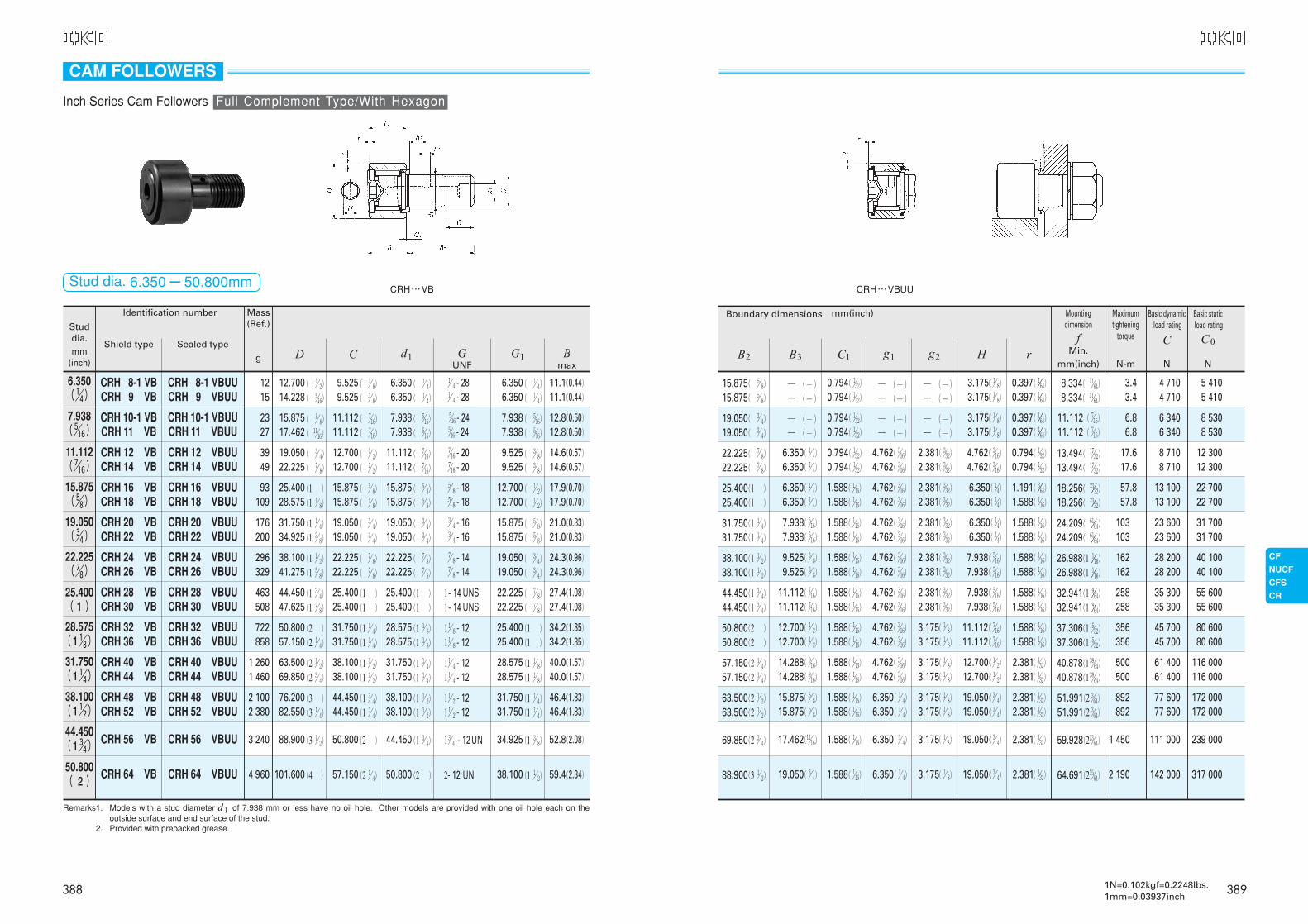
5 4105 410
8 5308 530
12 30012 300
22 70022 700
31 70031 700
40 10040 100
55 60055 600
80 60080 600
Boundary dimensions mm(inch)
15.875( %/ 8)
15.875( %/ 8)
0.794( !/32)
0.794( !/32)
0.397( !//64)
0.397( !//64)8.334( @!/64)
8.334( @!/64)
3.43.4
4 7104 710
─ (─)─ (─)
─ (─)─ (─)
─ (─)─ (─)
19.050( #/ 4)
19.050( #/ 4)
0.794( !/32)
0.794( !/32)
0.397( !//64)
0.397( !//64)
11.112( &/16)
11.112( &/16)
6.86.8
6 3406 340
─ (─)─ (─)
─ (─)─ (─)
─ (─)─ (─)
22.225( &/ 8)
22.225( &/ 8)
0.794( !/32)
0.794( !/32)
0.794( !/32)
0.794( !/32)13.494( !&/32)
13.494( !&/32)
17.617.6
8 7108 710
2.381( #/32)
2.381( #/32)
4.762( #/16)
4.762( #/16)
6.350( !/ 4)
6.350( !/ 4)
25.400(1 )
25.400(1 )
1.588( !/16)
1.588( !/16)
1.191( #//64)
1.588( !/16)18.256( @#//32)
18.256( @#//32)
57.857.8
13 10013 100
2.381( #/32)
2.381( #/32)
4.762( #/16)
4.762( #/16)
6.350( !/ 4)
6.350( !/ 4)
31.750(1 !/ 4)
31.750(1 !/ 4)
1.588( !/16)
1.588( !/16)
1.588( !/16)
1.588( !/16)24.209( ^!//64)
24.209( ^!//64)
103103
23 60023 600
2.381( #/32)
2.381( #/32)
4.762( #/16)
4.762( #/16)
7.938( %/16)
7.938( %/16)
38.100(1 !/ 2)
38.100(1 !/ 2)
1.588( !/16)
1.588( !/16)
1.588( !/16)
1.588( !/16)26.988(1 !//16)
26.988(1 !//16)
162162
28 20028 200
2.381( #/32)
2.381( #/32)
4.762( #/16)
4.762( #/16)
9.525( #/ 8)
9.525( #/ 8)
44.450(1 #/ 4)
44.450(1 #/ 4)
1.588( !/16)
1.588( !/16)
1.588( !/16)
1.588( !/16)32.941(1 !(//64)
32.941(1 !(//64)
258258
35 30035 300
2.381( #/32)
2.381( #/32)
4.762( #/16)
4.762( #/16)
11.112( &/16)
11.112( &/16)
50.800(2 )
50.800(2 )
1.588( !/16)
1.588( !/16)
1.588( !/16)
1.588( !/16)37.306(1 !%/32)
37.306(1 !%/32)
356356
45 70045 700
3.175( !/ 8)
3.175( !/ 8)
4.762( #/16)
4.762( #/16)
3.175( !/ 8)
3.175( !/ 8)
3.175( !/ 8)
3.175( !/ 8)
4.762( #/16)
4.762( #/16)
6.350( !/4)
6.350( !/4)
6.350( !/4)
6.350( !/4)
7.938( %/16)
7.938( %/16)
7.938( %/16)
7.938( %/16)
11.112( &/16)
11.112( &/16)
12.700( !/ 2)
12.700( !/ 2)
116 000116 000
172 000172 000
239 000
317 000
57.150(2 !/ 4)
57.150(2 !/ 4)
63.500(2 !/ 2)
63.500(2 !/ 2)
69.850(2 #/ 4)
88.900(3 !/ 2)
1.588( !/16)
1.588( !/16)
1.588( !/16)
1.588( !/16)
1.588( !/16)
1.588( !/16)
2.381( #/32)
2.381( #/32)
2.381( #/32)
2.381( #/32)
2.381( #/32)
2.381( #/32)
40.878(1 #(/64)
40.878(1 #(/64)
51.991(2 #/64)
51.991(2 #/64)
59.928(2@#/64)
64.691(2#%/64)
500500
892892
1 450
2 190
61 40061 400
77 60077 600
111 000
142 000
3.175( !/ 8)
3.175( !/ 8)
3.175( !/ 8)
3.175( !/ 8)
3.175( !/ 8)
3.175( !/ 8)
4.762( #/16)
4.762( #/16)
6.350( !/ 4)
6.350( !/ 4)
6.350( !/ 4)
6.350( !/ 4)
12.700( !/ 2)
12.700( !/ 2)
19.050( #/ 4)
19.050( #/ 4)
19.050( #/ 4)
19.050( #/ 4)
14.288( (/16)
14.288( (/16)
15.875( %/ 8)
15.875( %/ 8)
17.462(!!/16)
19.050( #/ 4)
B2 B3 C1 g1 g2 H r
Basic dynamicload rating
C
N
Basic staticload rating
C0
N
Mountingdimension
fMin.
mm(inch)
Maximumtightening
torque
N-m
CRH…VBUU
1N=0.102kgf=0.2248lbs.1mm=0.03937inch
Mass(Ref.)
g
6.350( !/4)
7.938( %/16)
11.112( &/16)
15.875( %/8)
19.050( #/4)
22.225( &/8)
25.400( 1 )
28.575(1 !/8)
Studdia.mm
(inch)
Identification number
Shield type Sealed type
CRH 8-1 VBUUCRH 9 VBUU
CRH 8-1 VBCRH 9 VB
CRH 10-1 VBUUCRH 11 VBUU
CRH 10-1 VBCRH 11 VB
CRH 12 VBUUCRH 14 VBUU
CRH 12 VBCRH 14 VB
CRH 16 VBUUCRH 18 VBUU
CRH 16 VBCRH 18 VB
CRH 20 VBUUCRH 22 VBUU
CRH 20 VBCRH 22 VB
CRH 24 VBUUCRH 26 VBUU
CRH 24 VBCRH 26 VB
CRH 28 VBUUCRH 30 VBUU
CRH 28 VBCRH 30 VB
CRH 32 VBUUCRH 36 VBUU
CRH 32 VBCRH 36 VB
Remarks1. Models with a stud diameter d1 of 7.938 mm or less have no oil hole. Other models are provided with one oil hole each on theoutside surface and end surface of the stud.
Remarks2. Provided with prepacked grease.
9.5259.525
6.3506.350
!/ 4 - 28!/ 4 - 28
6.3506.350
1215
11.11211.112
7.9387.938
%/16 - 24%/16 - 24
7.9387.938
2327
12.70012.700
11.11211.112
&/16 - 20&/16 - 20
9.5259.525
3949
15.87515.875
15.87515.875
%/ 8 - 18%/ 8 - 18
12.70012.700
93109
19.05019.050
19.05019.050
#/ 4 - 16#/ 4 - 16
15.87515.875
176200
22.22522.225
22.22522.225
&/ 8 - 14&/ 8 - 14
19.05019.050
296329
25.40025.400
25.40025.400
1- 141- 14
22.22522.225
463508
31.75031.750
28.57528.575
( !/ 4)
( !/ 4)
( %/16)
( %/16)
( &/16)
( &/16)
( %/ 8)
( %/ 8)
( #/ 4)
( #/ 4)
( &/ 8)
( &/ 8)
(1 )
(1 )
(1 !/ 8)
(1 !/ 8)
1 !/ 8 - 121 !/ 8 - 12
25.40025.400
( !/ 4)
( !/ 4)
( %/16)
( %/16)
( #/ 8)
( #/ 8)
( !/ 2)
( !/ 2)
( %/ 8)
( %/ 8)
( #/ 4)
( #/ 4)
( &/ 8)
( &/ 8)
(1 )
(1 )
722858
( !/ 2)
( (/16)
( %/ 8)
( !!/16)
( #/ 4)
( &/ 8)
(1 )
(1 !/ 8)
(1 !/ 4)
(1 #/ 8)
(1 !/ 2)
(1 %/ 8)
(1 #/ 4)
(1 &/ 8)
(2 )
(2 !/ 4)
12.70014.228
15.87517.462
19.05022.225
25.40028.575
31.75034.925
38.10041.275
44.45047.625
50.80057.150
( #/ 8)
( #/ 8)
( &/16)
( &/16)
( !/ 2)
( !/ 2)
( %/ 8)
( %/ 8)
( #/ 4)
( #/ 4)
( &/ 8)
( &/ 8)
(1 )
(1 )
(1 !/ 4)
(1 !/ 4)
31.750(1 !/4)
38.100(1 !/2)
44.450(1 #/4)
50.800( 2 )
CRH 40 VBUUCRH 44 VBUU
CRH 48 VBUUCRH 52 VBUU
CRH 56 VBUU
CRH 64 VBUU
CRH 40 VBCRH 44 VB
CRH 48 VBCRH 52 VB
CRH 56 VB
CRH 64 VB
38.10038.100
44.45044.450
50.800
57.150
31.75031.750
38.10038.100
44.450
50.800
(1 !/ 4)
(1 !/ 4)
(1 !/ 2)
(1 !/ 2)
(1 #/ 4)
(2 )
1 !/ 4 - 121 !/ 4 - 12
1 !/ 2 - 121 !/ 2 - 12
1 #/ 4 - 12UN
2- 12
(1 !/ 8)
(1 !/ 8)
(1 !/ 4)
(1 !/ 4)
(1 #/ 8)
(1 !/ 2)
1 2601 460
2 1002 380
3 240
4 960
(2 !/ 2)
(2 #/ 4)
(3 )
(3 !/ 4)
(3 !/ 2)
(4)!/02)
63.50069.850
76.20082.550
88.900
101.600
(1 !/ 2)
(1 !/ 2)
(1 #/ 4)
(1 #/ 4)
(2 )
(2 !/ 4)
28.57528.575
31.75031.750
34.925
38.100
11.1(0.44)11.1(0.44)
12.8(0.50)12.8(0.50)
14.6(0.57)14.6(0.57)
17.9(0.70)17.9(0.70)
21.0(0.83)21.0(0.83)
24.3(0.96)24.3(0.96)
27.4(1.08)27.4(1.08)
34.2(1.35)34.2(1.35)
40.0(1.57)40.0(1.57)
46.4(1.83)46.4(1.83)
52.8(2.08)
59.4(2.34)
Bmax
GUNF
G1D C d1
UNSUNS
UN
CRH…VB
CAM FOLLOWERS
Inch Series Cam Followers Full Complement Type/With Hexagon
Stud dia. 6.350-50.800mm
389388
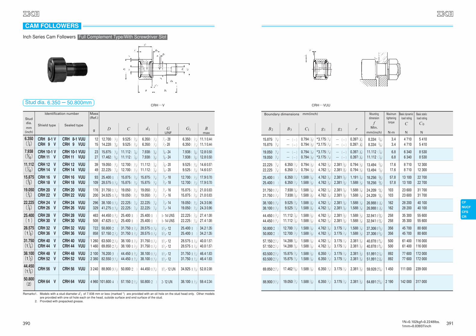
5 4105 410
8 5308 530
12 30012 300
22 70022 700
31 70031 700
40 10040 100
55 60055 600
80 60080 600
Boundary dimensions mm(inch)
15.875( %/ 8)
15.875( %/ 8)
0.794( !/32)
0.794( !/32)
0.397( !///64)
0.397( !///64)8.334( @!/64)
8.334( @!/64)
3.43.4
4 7104 710
─ (─)─ (─)
*3.175( !/ 8)
*3.175( !/ 8)─ (─)─ (─)
19.050( #/ 4)
19.050( #/ 4)
0.794( !/32)
0.794( !/32)
0.397( !//64)
0.397( !//64)
11.112( &/16)
11.112( &/16)
6.86.8
6 3406 340
─ (─)─ (─)
*3.175( !/ 8)
*3.175( !/ 8)─ (─)─ (─)
22.225( &/ 8)
22.225( &/ 8)
0.794( !/32)
0.794( !/32)
0.794( !/32)
0.794( !/32)13.494( !&/32)
13.494( !&/32)
17.617.6
8 7108 710
2.381( #/32)
2.381( #//32)
4.762( #/16)
4.762( #/16)
6.350( !/ 4)
6.350( !/ 4)
25.400(1 )
25.400(1 )
1.588( !/16)
1.588( !/16)
1.191( #/64)
1.588( !/16)18.256( @#//32)
18.256( @#//32)
57.857.8
13 10013 100
2.381( #/32)
2.381( #/32)
4.762( #/16)
4.762( #/16)
6.350( !/ 4)
6.350( !/ 4)
31.750(1 !/ 4)
31.750(1 !/ 4)
1.588( !/16)
1.588( !//16)
1.588( !/16)
1.588( !/16)24.209( ^!//64)
24.209( ^!//64)
103103
23 60023 600
2.381( #/32)
2.381( #/32)
4.762( #/16)
4.762( #/16)
7.938( %/16)
7.938( %/16)
38.100(1 !/ 2)
38.100(1 !/ 2)
1.588( !//16)
1.588( !//16)
1.588( !/16)
1.588( !/16)26.988(1 !//16)
26.988(1 !//16)
162162
28 20028 200
2.381( #/32)
2.381( #/32)
4.762( #/16)
4.762( #/16)
9.525( #/ 8)
9.525( #/ 8)
44.450(1 #/ 4)
44.450(1 #/ 4)
1.588( !/16)
1.588( !/16)
1.588( !/16)
1.588( !/16)32.941(1 !(//64)
32.941(1 !(//64)
258258
35 30035 300
2.381( #/32)
2.381( #/32)
4.762( #/16)
4.762( #/16)
11.112( &/16)
11.112( &/16)
50.800(2 )
50.800(2 )
1.588( !/16)
1.588( !/16)
1.588( !/16)
1.588( !/16)37.306(1 !%/32)
37.306(1 !%/32)
356356
45 70045 700
3.175( !/08)
3.175( !/08)
4.762( #/16)
4.762( #/16)
12.700( !/ 2)
12.700( !/ 2)
116 000116 000
172 000172 000
239 000
317 000
57.150(2 !/ 4)
57.150(2 !/ 4)
63.500(2 !/ 2)
63.500(2 !/ 2)
69.850(2 #/ 4)
88.900(3 !/ 2)
1.588( !/16)
1.588( !/16)
1.588( !/16)
1.588( !/16)
1.588( !/16)
1.588( !/16)
2.381( #/32)
2.381( #/32)
2.381( #/32)
2.381( #/32)
2.381( #/32)
2.381( #/32)
40.878(1 #(/64)
40.878(1 #(/64)
51.991(2 #/64)
51.991(2 #//64)
59.928(2@#/64)
64.691(2#%/64)
500500
892892
1 450
2 190
61 40061 400
77 60077 600
111 000
142 000
3.175( !/ 8)
3.175( !/ 8)
3.175( !/ 8)
3.175( !/ 8)
3.175( !/ 8)
3.175( !/ 8)
4.762( #/16)
4.762( #/16)
6.350( !/ 4)
6.350( !/ 4)
6.350( !/ 4)
6.350( !/ 4)
14.288( (/16)
14.288( (/16)
15.875( %/ 8)
15.875( %/ 8)
17.462(!!/16)
19.050( #/ 4)
B2 B3 C1 g1 g2 r
Basic dynamicload rating
C
N
Basic staticload rating
C0
N
Mountingdimension
fMin.
mm(inch)
Maximumtightening
torque
N-m
CRH…VUU
Mass(Ref.)
g
6.350( !/4)
7.938( %/16)
11.112( &/16)
15.875( %/8)
19.050( #/4)
22.225( &/8)
25.400( 1 )
28.575(1 !/8)
Studdia.mm
(inch)
Identification number
Shield type Sealed type
CRH 8-1 VUUCRH 9 VUU
CRH 8-1 VCRH 9 V
CRH 10-1 VUUCRH 11 VUU
CRH 10-1 VCRH 11 V
CRH 12 VUUCRH 14 VUU
CRH 12 VCRH 14 V
CRH 16 VUUCRH 18 VUU
CRH 16 VCRH 18 V
CRH 20 VUUCRH 22 VUU
CRH 20 VCRH 22 V
CRH 24 VUUCRH 26 VUU
CRH 24 VCRH 26 V
CRH 28 VUUCRH 30 VUU
CRH 28 VCRH 30 V
CRH 32 VUUCRH 36 VUU
CRH 32 VCRH 36 V
Remarks1. Models with a stud diameter d1 of 7.938 mm or less (marked *) are provided with an oil hole on the stud head only. Other modelsare provided with one oil hole each on the head, outside surface and end surface of the stud.
Remarks2. Provided with prepacked grease.
11.1(0.44)11.1(0.44)
12.8(0.50)12.8(0.50)
14.6(0.57)14.6(0.57)
17.9(0.70)17.9(0.70)
21.0(0.83)21.0(0.83)
24.3(0.96)24.3(0.96)
27.4(1.08)27.4(1.08)
34.2(1.35)34.2(1.35)
9.5259.525
6.3506.350
!/ 4 - 28!/ 4- 28
6.3506.350
1215
11.11211.112
7.9387.938
%/16 - 24%/16 - 24
7.9387.938
2327
12.70012.700
11.11211.112
&/16 - 20&/16 - 20
9.5259.525
3949
15.87515.875
15.87515.875
%/ 8 - 18%/ 8 - 18
12.70012.700
93109
19.05019.050
19.05019.050
#/ 4 - 16#/ 4 - 16
15.87515.875
176200
22.22522.225
22.22522.225
&/ 8 - 14&/ 8 - 14
19.05019.050
296329
25.40025.400
25.40025.400
1- 141- 14
22.22522.225
463508
31.75031.750
28.57528.575
( !/ 4)
( !/ 4)
( %/16)
( %/16)
( &/16)
( &/16)
( %/ 8)
( %/ 8)
( #/ 4)
( #/ 4)
( &/ 8)
( &/ 8)
(1 )
(1 )
(1 !/ 8)
(1 !/ 8)
1 !/ 8 - 121 !/ 8 - 12
25.40025.400
( !/ 4)
( !/ 4)
( %/16)
( %/16)
( #/ 8)
( #/ 8)
( !/ 2)
( !/ 2)
( %/ 8)
( %/ 8)
( #/ 4)
( #/ 4)
( &/ 8)
( &/ 8)
(1 )
(1 )
722858
( !/ 2)
( (/16)
( %/ 8)
( !!/16)
( #/ 4)
( &/ 8)
(1 )
(1 !/ 8)
(1 !/ 4)
(1 #/ 8)
(1 !/ 2)
(1 %/ 8)
(1 #/ 4)
(1 &/ 8)
(2 )
(2 !/ 4)
12.70014.228
15.87517.462
19.05022.225
25.40028.575
31.75034.925
38.10041.275
44.45047.625
50.80057.150
( #/ 8)
( #/ 8)
( &/16)
( &/16)
( !/ 2)
( !/ 2)
( %/ 8)
( %/ 8)
( #/ 4)
( #/ 4)
( &/ 8)
( &/ 8)
(1 )
(1 )
(1 !/ 4)
(1 !/ 4)
31.750(1 !/4)
38.100(1 !/2)
44.450(1 #/4)
50.800(2)
CRH 40 VUUCRH 44 VUU
CRH 48 VUUCRH 52 VUU
CRH 56 VUU
CRH 64 VUU
CRH 40 VCRH 44 V
CRH 48 VCRH 52 V
CRH 56 V
CRH 64 V
40.0(1.57)40.0(1.57)
46.4(1.83)46.4(1.83)
52.8(2.08)
59.4(2.34)
38.10038.100
44.45044.450
50.800
57.150
31.75031.750
38.10038.100
44.450
50.800
(1 !/ 4)
(1 !/ 4)
(1 !/ 2)
(1 !/ 2)
(1 #/ 4)
(2 )
1 !/ 4 - 121 !/ 4 - 12
1 !/ 2 - 121 !/ 2 - 12
1 #/ 4 - 12 UN
2- 12 UN
(1 !/ 8)
(1 !/ 8)
(1 !/ 4)
(1 !/ 4)
(1 #/ 8)
(1 !/ 2)
1 2601 460
2 1002 380
3 240
4 960
(2 !/ 2)
(2 #/ 4)
(3 )
(3 !/ 4)
(3 !/ 2)
(4 )
63.50069.850
76.20082.550
88.900
101.600
(1 !/ 2)
(1 !/ 2)
(1 #/ 4)
(1 #/ 4)
(2 )
(2 !/ 4)
28.57528.575
31.75031.750
34.925
38.100
UNSUNS
CRH…V
CAM FOLLOWERS
Inch Series Cam Followers Full Complement Type/With Screwdriver Slot
Stud dia. 6.350-50.800mm
Bmax
GUNF
G1D C d1
390 3911N=0.102kgf=0.2248lbs.1mm=0.03937inch