Embed Size (px)
Citation preview
Structural Design Guide for Prestressed Slabs
VO
L. 0
2
Structural Design Guide for Prestressed Slabs
VOL. 02 STRUCTURE INSIGHT
Chapter 1 What is Post-Tensioning
1.1 Advantages & Applications of Post-Tensioning 1
1.1.1 Post-tension type 2
1.2 Strength of Prestressing Steel 3
1.3 Design Steps 4
1.4 Loading Conditions 5
1.5 Definition of Member Forces 6
1.6 Thickness or Depth of Section 7
1.7 Post Tension Slab Procedure 8
Chapter 2 Design Flow for Post-Tension
2.1 Choose Tendon Force and Profile 12
2.1.1 Tendon profile type 12
2.1.2 How to arrange tendon of parabolic shape 13
2.2 Check Final Stresses, Check Initial Stresses 14
2.2.1 Allowable stress for concrete 14
2.2.2 Allowable stress for tendon (Strand) 14
2.2.3 Calculate & check stresses in simple beam 14
2.2.4 Stress distribution according to tendon arrangement 17
2.3 Check Prestress Losses 17
2.3.1 Kind and calculation of loss 18
2.4 Check Flexural Strength 21
2.4.1 Calculation of flexural strength 21
2.5 Check Shear Strength 22
3.1 Tip for Post-Tension Design 25
3.1.1 Assumption in post-tension design 25
3.1.2 Arrangement of tendon 26
3.2 Extra Rebar (Additional Rebar) 27
3.2.1 Extra rebar in unbonded type 27
3.2.2 Extra rebar in bonded type 30
3.3 Building Design Example 30
3.3.1 Building information 30
3.3.2 Service stage 30
3.3.3 Calculation of secondary moment 32
3.3.4 Calculation of design moment 32
3.3.5 Calculation of flexural strength (Mn) 32
3.3.6 Check punching shear 33
Chapter 3 Post-Tension Design Tip and Example

Chapter 4 Tutorial for Post-Tension Beam
4.1 Modeling of Post-Tension Beam 34
4.1.1 Tendon material definition 35
4.1.2 Post-tensioning tendon property 36
4.1.3 Tendon profile definition 36
4.2 Loading of Prestressing Loads 39
4.2.1 Apply prestressing loads to the tendons 39
4.2.2 Activate prestressing loads in construction stage 40
Chapter 1
What is Post-Tensioning
Chapter 1
What is Post-Tensioning
Structural Design Guide for Prestressed Slabs 1
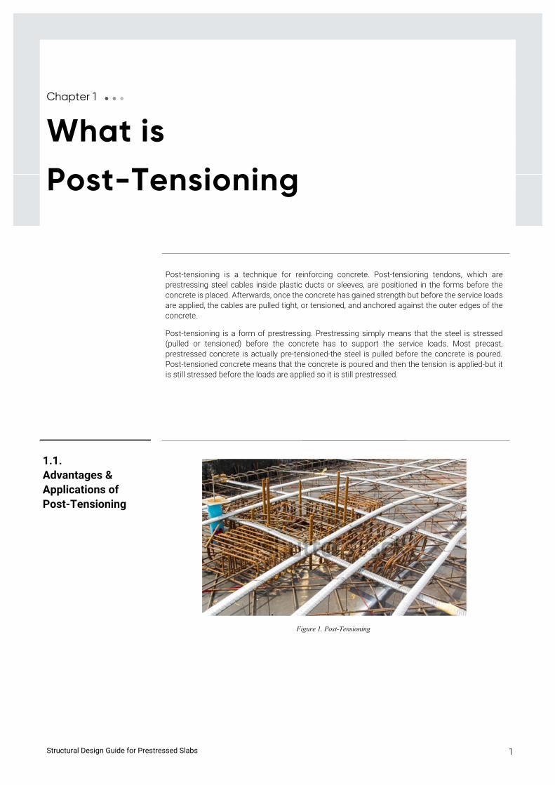
Post-tensioning is a technique for reinforcing concrete. Post-tensioning tendons, which are prestressing steel cables inside plastic ducts or sleeves, are positioned in the forms before the concrete is placed. Afterwards, once the concrete has gained strength but before the service loads are applied, the cables are pulled tight, or tensioned, and anchored against the outer edges of the concrete.
Post-tensioning is a form of prestressing. Prestressing simply means that the steel is stressed (pulled or tensioned) before the concrete has to support the service loads. Most precast, prestressed concrete is actually pre-tensioned-the steel is pulled before the concrete is poured. Post-tensioned concrete means that the concrete is poured and then the tension is applied-but it is still stressed before the loads are applied so it is still prestressed.
Figure 1. Post-Tensioning
1.1. Advantages & Applications of Post-Tensioning
Structural Design Guide for Prestressed Slabs 2
• It reduces or eliminates shrinkage cracking-therefore no joints, or fewer joints, are needed.
• Cracks that do form are held tightly together.
• It allows slabs and other structural members to be thinner.
• It allows us to build slabs on expansive or soft soils.
• It lets us design longer spans in elevated members, like floors or beam.
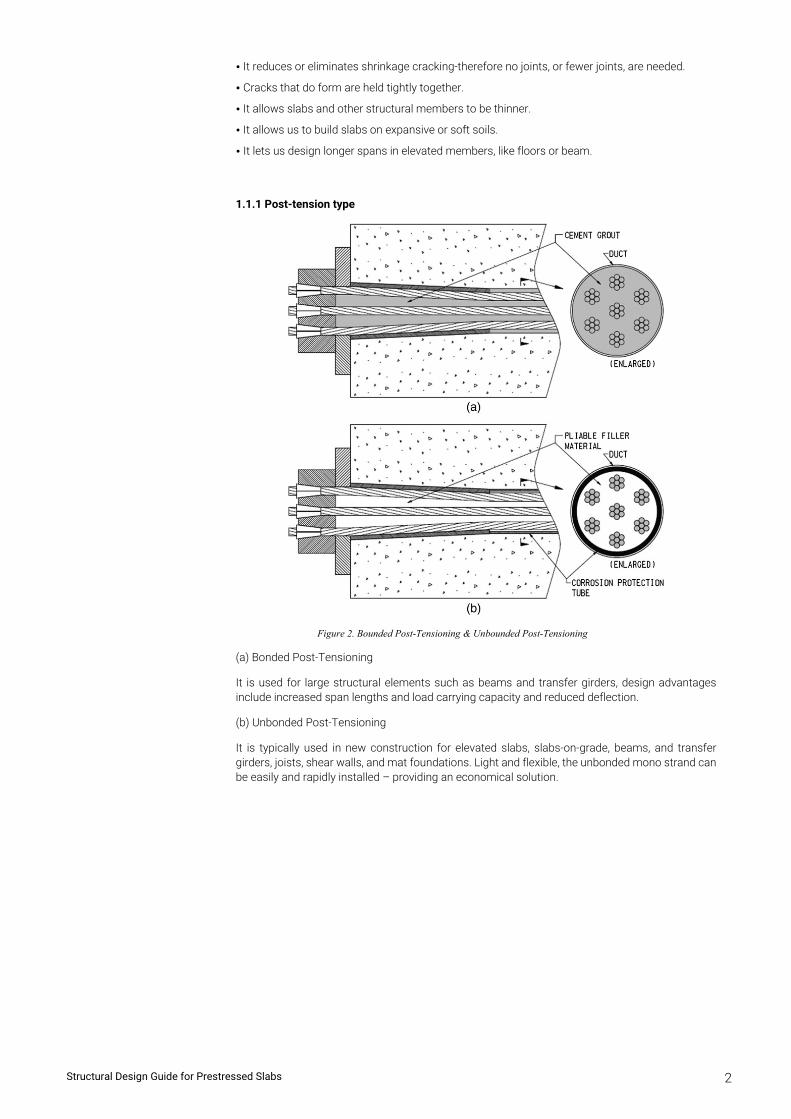
1.1.1 Post-tension type
Figure 2. Bounded Post-Tensioning & Unbounded Post-Tensioning
(a) Bonded Post-Tensioning
It is used for large structural elements such as beams and transfer girders, design advantages include increased span lengths and load carrying capacity and reduced deflection.
(b) Unbonded Post-Tensioning
It is typically used in new construction for elevated slabs, slabs-on-grade, beams, and transfer girders, joists, shear walls, and mat foundations. Light and flexible, the unbonded mono strand can be easily and rapidly installed – providing an economical solution.
Structural Design Guide for Prestressed Slabs 3
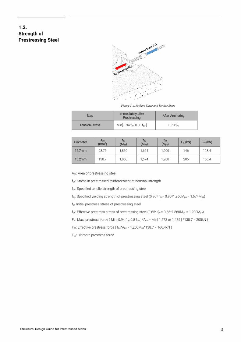
Figure 3-a. Jacking Stage and Service Stage
Step Immediately after
Prestressing After Anchoring
Tension Stress Min[ 0.94 fpy, 0.80 fpu ] 0.70 fpu
Diameter Aps
(mm2) fpu
(Mpa) fpy
(Mpa) fpe
(Mpa) Fst (kN) Fse (kN)
12.7mm 98.71 1,860 1,674 1,200 146 118.4
15.2mm 138.7 1,860 1,674 1,200 205 166.4
Aps: Area of prestressing steel
fps: Stress in prestressed reinforcement at nominal strength
fpu: Specified tensile strength of prestressing steel
fpy: Specified yielding strength of prestressing steel (0.90* fpu= 0.90*1,860Mpa = 1,674Mpa)
fpi: Initial prestress stress of prestressing steel
fpe: Effective prestress stress of prestressing steel (0.65* fpu= 0.65*1,860Mpa = 1,200Mpa)
Fst: Max. prestress force ( Min[ 0.94 fpy, 0.8 fpu ] *Aps = Min[ 1,573 or 1,485 ] *138.7 = 205kN )
Fse: Effective prestress force ( fpe*Aps = 1,200Mpa*138.7 = 166.4kN )
Fps: Ultimate prestress force
1.2. Strength of Prestressing Steel
Structural Design Guide for Prestressed Slabs 4
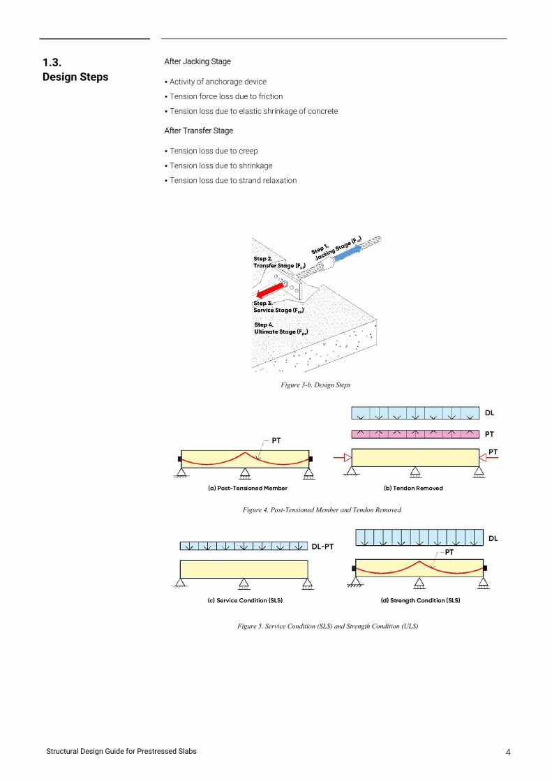
After Jacking Stage
• Activity of anchorage device
• Tension force loss due to friction
• Tension loss due to elastic shrinkage of concrete
After Transfer Stage
• Tension loss due to creep
• Tension loss due to shrinkage
• Tension loss due to strand relaxation
Figure 3-b. Design Steps
Figure 4. Post-Tensioned Member and Tendon Removed.
Figure 5. Service Condition (SLS) and Strength Condition (ULS)
1.3. Design Steps
Structural Design Guide for Prestressed Slabs 5
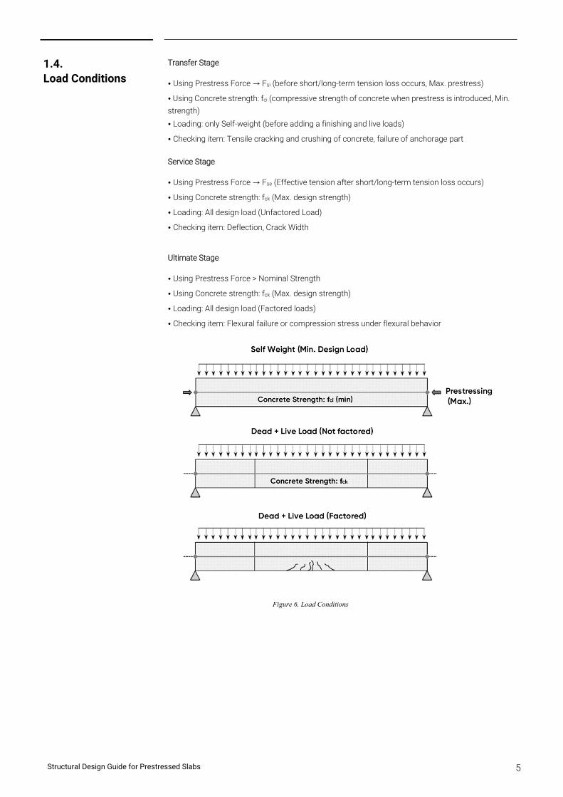
Transfer Stage
• Using Prestress Force → Fsi (before short/long-term tension loss occurs, Max. prestress)
• Using Concrete strength: fci (compressive strength of concrete when prestress is introduced, Min.
strength)
• Loading: only Self-weight (before adding a finishing and live loads)
• Checking item: Tensile cracking and crushing of concrete, failure of anchorage part
Service Stage
• Using Prestress Force → Fse (Effective tension after short/long-term tension loss occurs)
• Using Concrete strength: fck (Max. design strength)
• Loading: All design load (Unfactored Load)
• Checking item: Deflection, Crack Width
Ultimate Stage
• Using Prestress Force > Nominal Strength
• Using Concrete strength: fck (Max. design strength)
• Loading: All design load (Factored loads)
• Checking item: Flexural failure or compression stress under flexural behavior
Figure 6. Load Conditions
1.4. Load Conditions
Structural Design Guide for Prestressed Slabs 6
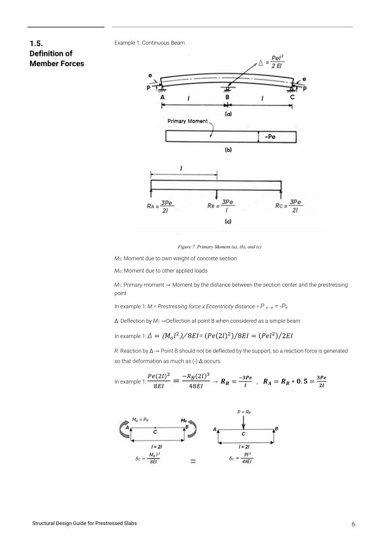
Example 1: Continuous Beam
Figure 7. Primary Moment (a), (b), and (c)
MS: Moment due to own weight of concrete section
MO: Moment due to other applied loads
M1: Primary moment → Moment by the distance between the section center and the prestressing
point
In example 1: M = Prestressing force x Eccentricity distance = P x - e = -Pe
Δ: Deflection by M1 →Deflection at point B when considered as a simple beam
In example 1: ∆ 𝑀 𝑙 8𝐸𝐼⁄ = 𝑃𝑒 2𝑙 8𝐸𝐼⁄ 𝑃𝑒𝑙 2𝐸𝐼⁄
R: Reaction by Δ → Point B should not be deflected by the support, so a reaction force is generated
so that deformation as much as (-) Δ occurs.
In example 1: → 𝑹𝑩𝟑𝑷𝒆
𝒍 , 𝑹𝑨 𝑹𝑩 ∗ 𝟎. 𝟓
𝟑𝑷𝒆
𝟐𝒍
1.5. Definition of Member Forces
Structural Design Guide for Prestressed Slabs 7
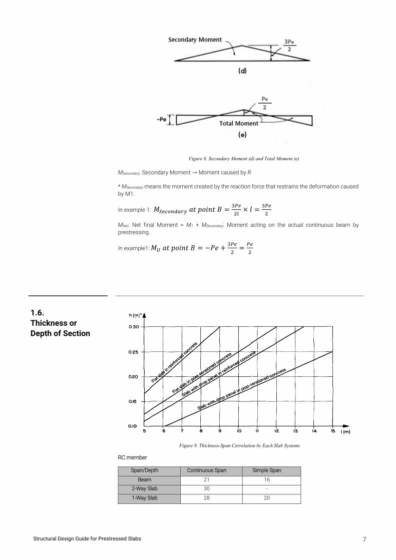
Figure 8. Secondary Moment (d) and Total Moment (e)
MSecondary: Secondary Moment → Moment caused by R
* MSecondary means the moment created by the reaction force that restrains the deformation caused by M1.
In example 1: 𝑀 𝑎𝑡 𝑝𝑜𝑖𝑛𝑡 𝐵 𝑙
MNet: Net final Moment = M1 + MSecondary: Moment acting on the actual continuous beam by prestressing.
In example1: 𝑀 𝑎𝑡 𝑝𝑜𝑖𝑛𝑡 𝐵 𝑃𝑒
Figure 9. Thickness-Span Correlation by Each Slab Systems
RC member
Span/Depth Continuous Span Simple Span
Beam 21 16
2-Way Slab 30 -
1-Way Slab 28 20
1.6. Thickness or Depth of Section
Structural Design Guide for Prestressed Slabs 8
Post-Tension Member
Span/Depth
Continuous Span Simple Span
Roof Not Roof Roof Not Roof
Beam 35 30 30 26
2-Way Slab 48 42 - -
1-Way Slab 50 45 45 40
Reduction Ratio of Thickness or Depth when PT is applied.
Span/Depth(%)
Continuous Span Simple Span
Roof Not Roof Roof Not Roof
Beam 60% 70% 53% 62%
2-Way Slab 63% 71% - -
1-Way Slab 56% 62% 44% 50%
The thickness is reduced by 30-50% compared to the RC member. Alternatively, an economical design can be made by reducing the amount of rebar or tendon required for the same thickness.
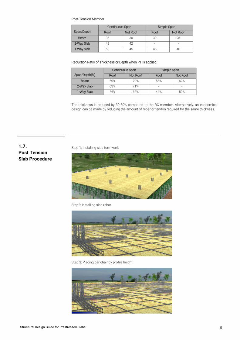
Step 1: Installing slab formwork
Step2: Installing slab rebar
Step 3: Placing bar chair by profile height
1.7. Post Tension Slab Procedure
Structural Design Guide for Prestressed Slabs 9
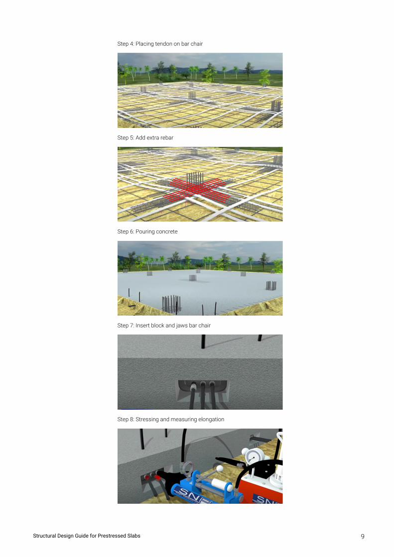
Step 4: Placing tendon on bar chair
Step 5: Add extra rebar
Step 6: Pouring concrete
Step 7: Insert block and jaws bar chair
Step 8: Stressing and measuring elongation
Structural Design Guide for Prestressed Slabs 10
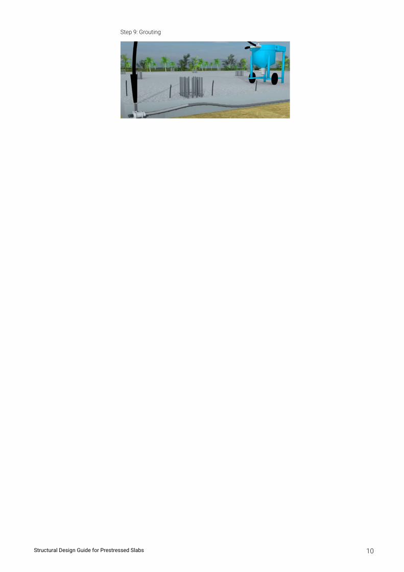
Step 9: Grouting
Chapter 2
Design Flow for Post-Tension System
Chapter 2
Design Flow for Post-Tension
Structural Design Guide for Prestressed Slabs 11
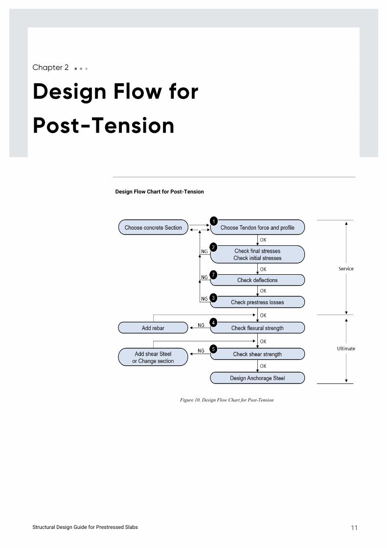
Design Flow Chart for Post-Tension
Figure 10. Design Flow Chart for Post-Tension
Structural Design Guide for Prestressed Slabs 12
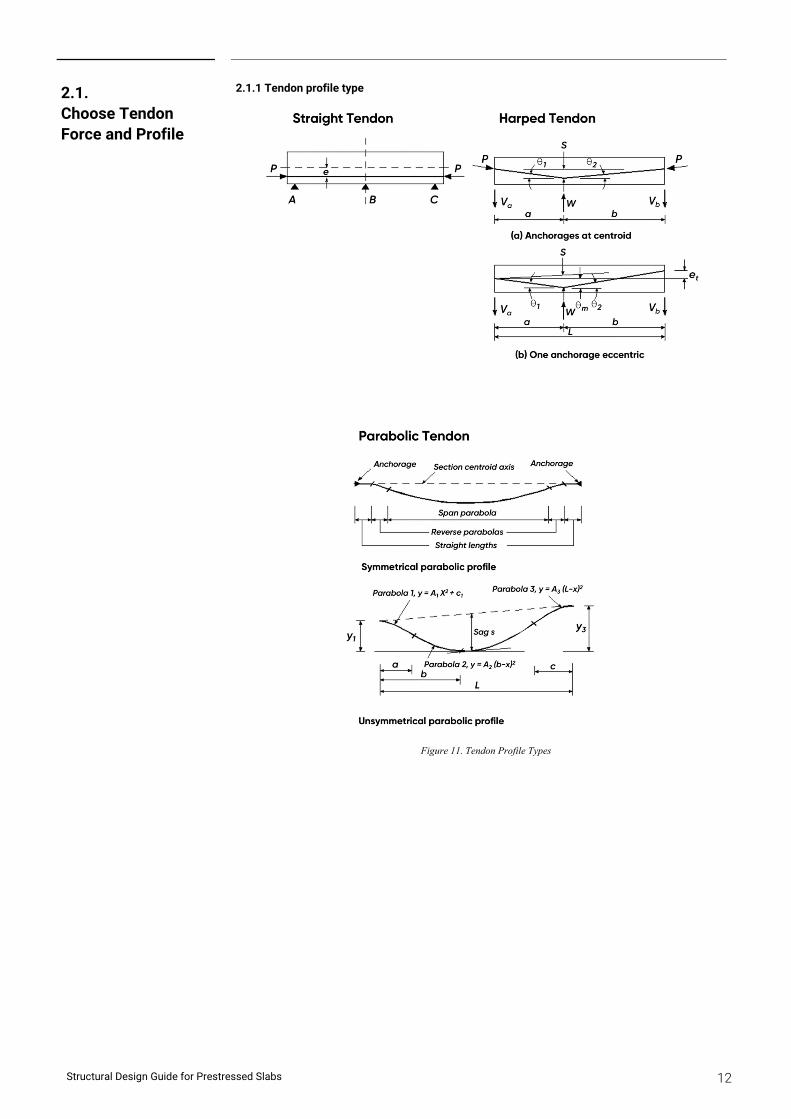
2.1.1 Tendon profile type
Figure 11. Tendon Profile Types
2.1. Choose Tendon Force and Profile
Structural Design Guide for Prestressed Slabs 13
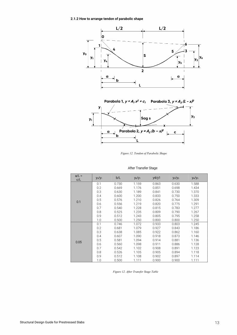
2.1.2 How to arrange tendon of parabolic shape
Figure 12. Tendon of Parabolic Shape
After Transfer Stage
a/L = c/L
y3/y1 b/L y0/y1 y4/y1 y5/y3 y6/y3
0.1
0.1 0.730 1.159 0.863 0.630 1.588 0.2 0.669 1.176 0.851 0.698 1.434 0.3 0.630 1.189 0.841 0.730 1.370 0.4 0.600 1.200 0.833 0.750 1.333 0.5 0.576 1.210 0.826 0.764 1.309 0.6 0.556 1.219 0.820 0.775 1.291 0.7 0.540 1.228 0.815 0.783 1.277 0.8 0.525 1.235 0.809 0.790 1.267 0.9 0.512 1.243 0.805 0.795 1.258 1.0 0.500 1.250 0.800 0.800 1.250
0.05
0.1 0.746 1.072 0.933 0.803 1.245 0.2 0.681 1.079 0.927 0.843 1.186 0.3 0.638 1.085 0.922 0.862 1.160 0.4 0.607 1.090 0.918 0.873 1.146 0.5 0.581 1.094 0.914 0.881 1.136 0.6 0.560 1.098 0.911 0.886 1.128 0.7 0.542 1.102 0.908 0.891 1.123 0.8 0.526 1.105 0.905 0.894 1.118 0.9 0.512 1.108 0.902 0.897 1.114 1.0 0.500 1.111 0.900 0.900 1.111
Figure 12. After Transfer Stage Table
Structural Design Guide for Prestressed Slabs 14
2.2.1 Allowable stress for concrete
Checking Stage
Conditions Allowable Stress
Under Initial Service Load (Initial)
1. Extreme fiber stress in compression pci = 0.60 fci
2. Extreme fiber stress in tension pti = 0.25 fci0.5
3. Extreme fiber stress in tension at ends of simply supported members
pti = 0.50 fci0.5
Under Service Load
(Final)
1. Extreme fiber stress in compression (at Long-Term Service Load)
pcf = 0.45 fck
2. Extreme fiber stress in compression (prestress + total load)
pcf = 0.60 fck
3. Extreme fiber stress in tension ptf = 0.50 fck0.5
2.2.2 Allowable stress for tendon (Strand)
Checking Stage Conditions Allowable Stress
During Stressing - Max [0.94 fpy, 0.8fpu]
Immediately after Stressing
- 0.70fpu
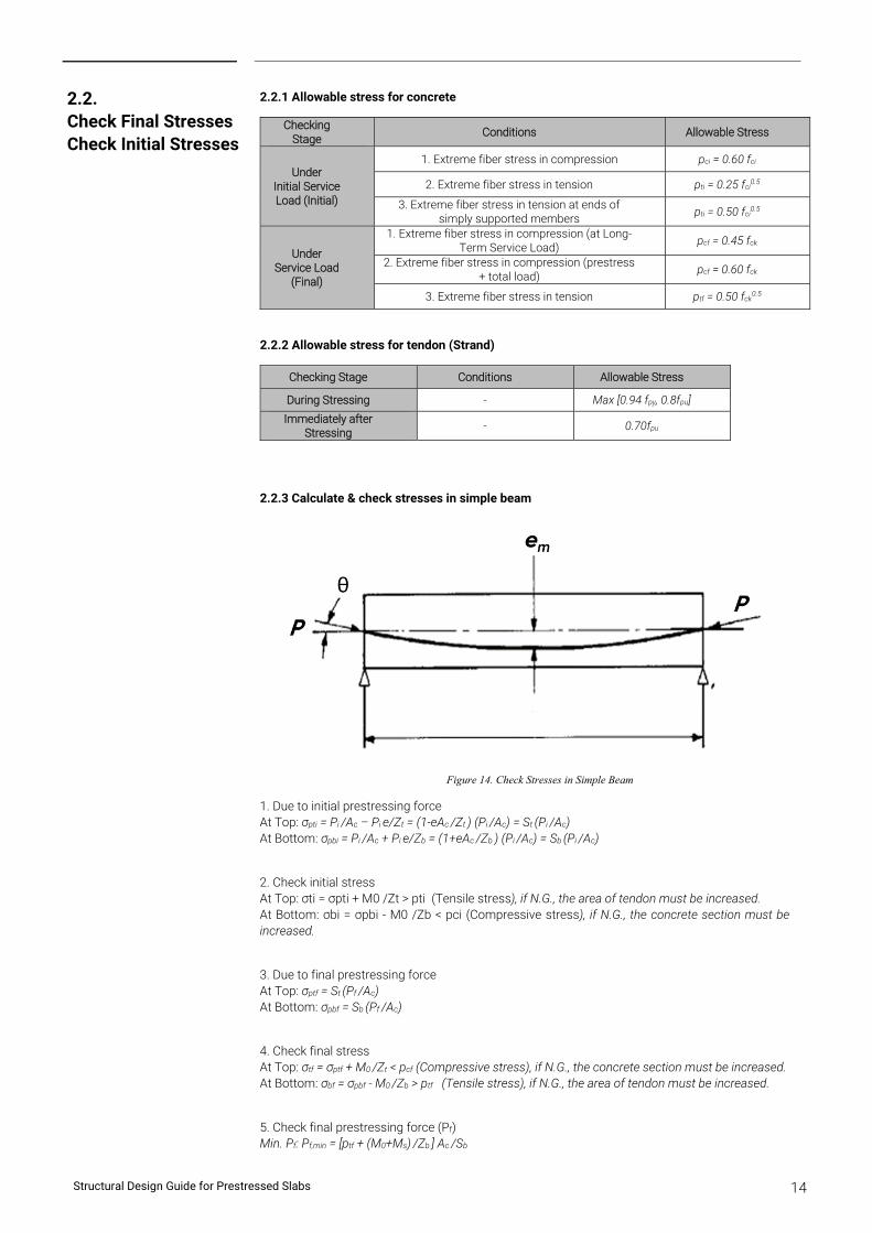
2.2.3 Calculate & check stresses in simple beam
Figure 14. Check Stresses in Simple Beam
1. Due to initial prestressing force At Top: σpti = Pi /Ac – Pi e/Zt = (1-eAc /Zt ) (Pi /Ac) = St (Pi /Ac) At Bottom: σpbi = Pi /Ac + Pi e/Zb = (1+eAc /Zb ) (Pi /Ac) = Sb (Pi /Ac)
2. Check initial stress At Top: σti = σpti + M0 /Zt > pti (Tensile stress), if N.G., the area of tendon must be increased. At Bottom: σbi = σpbi - M0 /Zb < pci (Compressive stress), if N.G., the concrete section must be increased.
3. Due to final prestressing force At Top: σptf = St (Pf /Ac) At Bottom: σpbf = Sb (Pf /Ac)
4. Check final stress At Top: σtf = σptf + M0 /Zt < pcf (Compressive stress), if N.G., the concrete section must be increased. At Bottom: σbf = σpbf - M0 /Zb > ptf (Tensile stress), if N.G., the area of tendon must be increased.
5. Check final prestressing force (Pf) Min. Pf: Pf,min = [ptf + (M0+Ms) /Zb ] Ac /Sb
2.2. Check Final Stresses Check Initial Stresses
Structural Design Guide for Prestressed Slabs 15
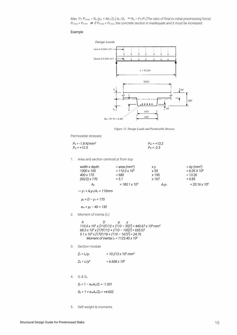
Max. Pf: Pf,max = Rp (pci + M0 /Zb ] Ac /Sb ** Rp = Pf /Pi (The ratio of final to initial prestressing force) Pf,max > Pf,min If Pf,max > Pf,min, the concrete section in inadequate and it must be increased. Example
Figure 15. Design Loads and Permissible Stresses
Permissible stresses:
Pti = -1.8 N/mm2 Pcf = +13.2 Pci = +12.5 Ptf = -2.3
1. Area and section centroid yt from top
width x depth = area (mm2) x y = Ay (mm2) 1000 x 100 = 110.0 x 103 x 55 = 6.05 X 10⁶ 400 x 170 = 680 x 195 = 13.26 (60/2) x 170 = 5.1 x 167 = 0.85
Ae = 183.1 x 10³ Acy1 = 20.16 x 10⁶
→ y1 = Acy1/Ac = 110mm
yb = D – y1 = 170
em = yb – 40 = 130
2. Moment of inertia (IC)
A D yt y 110.0 x 103 x [1102/12 + (110 – 55)2] = 443.67 x 106 mm4 68.0 x 103 x [1702/12 + (110 – 195)2] = 655.07 5.1 x 103 x [1702/18 + (110 – 167)2] = 24.76
Moment of inertia Ic = 1123.40 x 106
3. Section module
Zt = Ic/yt = 10.213 x 106 mm3
Zb = Ic/yb = 6.608 x 10⁶
4. St & Sb
St = 1 – emAc/Zt = -1.331
Sb = 1 + emAc/Zb = +4.602
5. Self-weight & moments
Structural Design Guide for Prestressed Slabs 16
Section weight = 24 x 183.1/1000 = 4.39 kN/m2
Moments:
Mo = 4.39 x 10²/8 = 54.9 kN.m/m self-weight
Ms = 6.00 x 10²/8 = 75.0 other loads
Mo + Ms = 129.9 total
6. Prestressing forces
Check final prestressing force (Pf):
Min. Pf: Pf,min = [ptf + (M0+Ms) /Zb ] Ac /Sb
= [-2.3 + 129.9/6.608] * 183.1/4.602 = 690.6 kN
Max. Pf: Pf,max = Rp (pci + M0 /Zb ] Ac /Sb
= 0.85 * (12.5 + 54.9/6.608) * 183.1/4.602 = 703.7 kN
Check: Pf,max = 690.6 > Pf,min = 703.7 O.K.
Use Pf = 690.6 kN, Pi = Pf / 0.85 = 812 kN
7. Number of strands per rib
Assuming 160kN final force per 15.7mm strand,
the number of strands per rib = 690.6/160 = 4.3... apply 5
8. Check stresses
From 4.
St = 1 – emAc/Zt = -1.331
Sb = 1 + emAc/Zb = +4.602
Stresses:
Pi/Ac = 812.5/183.1 = 4.44 N/mm2
σpti = StPi/Ac = -5.91
σpbi = SbPi/Ac = 20.43
Pf/Ac = 690.6/183.1 = 3.77 N/mm2
σptf = StPf/Ac = -5.02
σpbf = SbPf/Ac = 17.36
Initial Stresses
σtj = -5.91 + 54.9/10.213 = -0.53 > Pti
σbi = +20.43 – 53.4/6.608 =+12.35 < Pci
Final Stresses
σtf = = -0.53 > Pti
σbf = +20.43 – 53.4/6.608 =+12.35 < Pci
Structural Design Guide for Prestressed Slabs 17
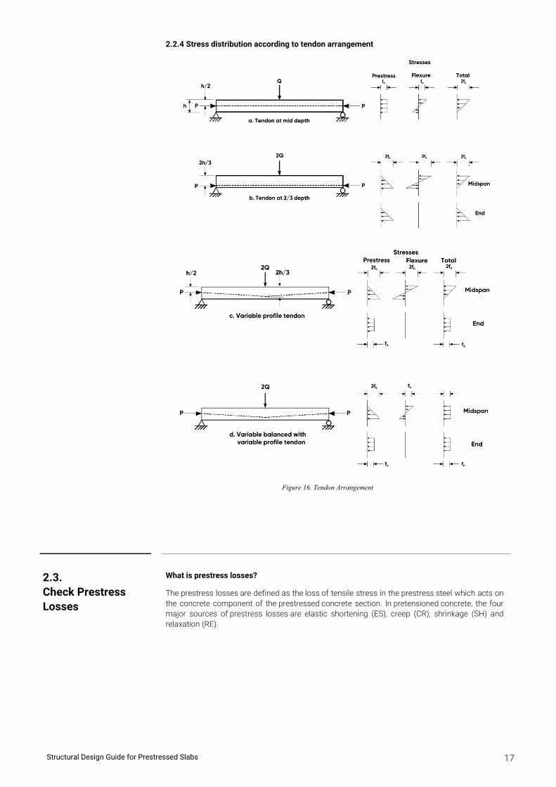
2.2.4 Stress distribution according to tendon arrangement
Figure 16. Tendon Arrangement
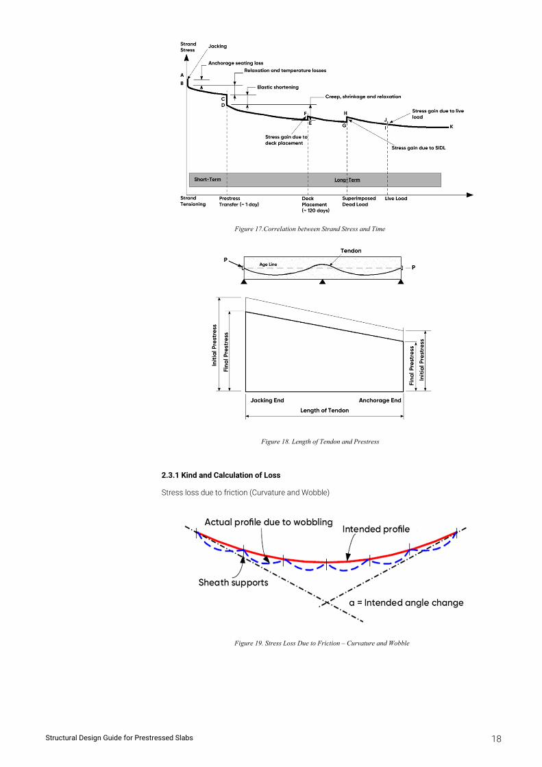
What is prestress losses?
The prestress losses are defined as the loss of tensile stress in the prestress steel which acts on the concrete component of the prestressed concrete section. In pretensioned concrete, the four major sources of prestress losses are elastic shortening (ES), creep (CR), shrinkage (SH) and relaxation (RE).
2.3. Check Prestress Losses
Structural Design Guide for Prestressed Slabs 18
Figure 17.Correlation between Strand Stress and Time
Figure 18. Length of Tendon and Prestress
2.3.1 Kind and Calculation of Loss
Stress loss due to friction (Curvature and Wobble)
Figure 19. Stress Loss Due to Friction – Curvature and Wobble
Structural Design Guide for Prestressed Slabs 19
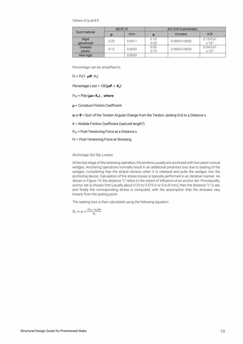
Values of μ and K
Duct material BS 8110 ACI 318 Commentary
μ K/m μ K/metre K/ft
Rigid galvanized
0.25 0.0017 0.15-0.25
0.0005-0.0020 0.15-0.61
x 10-3 Greased plastic
0.12 0.0025 0.05-0.15
0.0003-0.0020 0.09-0.61
x 10-3 Non-rigid 0.0033
Percentage can be simplified to:
Px = P0(1- μθ - Kx)
Percentage Loss = 100(μθ + Kx)
P(X) = P0e-(μα+Kx) , where
μ = Curvature Friction Coefficient
α or θ = Sum of the Tendon Angular Change from the Tendon Jacking End to a Distance x
K = Wobble Friction Coefficient (rad/unit length2)
P(x) = Post-Tensioning Force at a Distance x
P0 = Post-Tensioning Force at Stressing
Anchorage Set Slip Losses
At the last stage of the stressing operation, the tendons usually are anchored with two-piece conical wedges. Anchoring operations normally result in an additional prestress loss due to seating of the wedges, considering that the strand retracts when it is released and pulls the wedges into the anchoring device. Calculation of the stress losses is typically performed in an iterative manner. As shown in Figure 19, the distance “c” refers to the extent of influence of an anchor set. Procedurally, anchor set is chosen first (usually about 0.25 to 0.375 in or 6 to 8 mm), then the distance “c” is set, and finally the corresponding stress is computed, with the assumption that the stresses vary linearly from the jacking point.
The seating loss is then calculated using the following equation:
SL 𝑎
Structural Design Guide for Prestressed Slabs 20
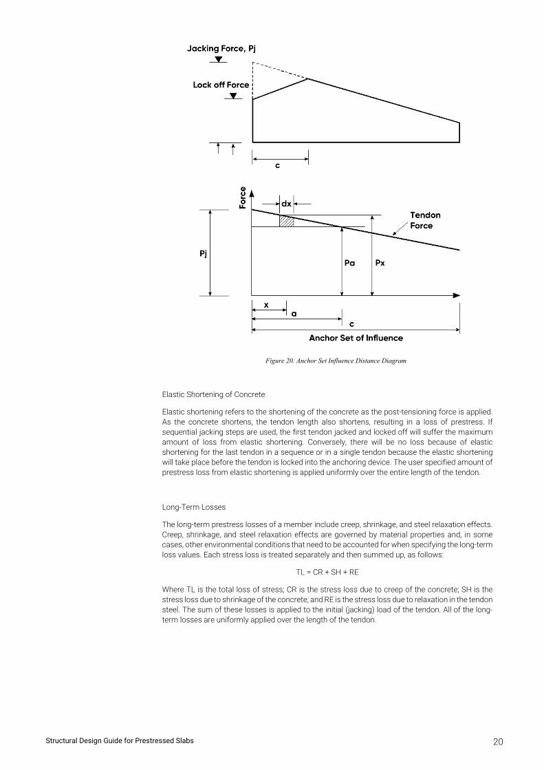
Figure 20. Anchor Set Influence Distance Diagram
Elastic Shortening of Concrete
Elastic shortening refers to the shortening of the concrete as the post-tensioning force is applied. As the concrete shortens, the tendon length also shortens, resulting in a loss of prestress. If sequential jacking steps are used, the first tendon jacked and locked off will suffer the maximum amount of loss from elastic shortening. Conversely, there will be no loss because of elastic shortening for the last tendon in a sequence or in a single tendon because the elastic shortening will take place before the tendon is locked into the anchoring device. The user specified amount of prestress loss from elastic shortening is applied uniformly over the entire length of the tendon.
Long-Term Losses
The long-term prestress losses of a member include creep, shrinkage, and steel relaxation effects. Creep, shrinkage, and steel relaxation effects are governed by material properties and, in some cases, other environmental conditions that need to be accounted for when specifying the long-term loss values. Each stress loss is treated separately and then summed up, as follows:
TL = CR + SH + RE
Where TL is the total loss of stress; CR is the stress loss due to creep of the concrete; SH is the stress loss due to shrinkage of the concrete; and RE is the stress loss due to relaxation in the tendon steel. The sum of these losses is applied to the initial (jacking) load of the tendon. All of the long-term losses are uniformly applied over the length of the tendon.
Structural Design Guide for Prestressed Slabs 21
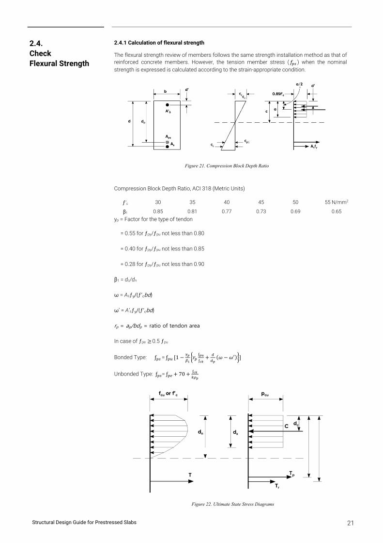
2.4.1 Calculation of flexural strength
The flexural strength review of members follows the same strength installation method as that of reinforced concrete members. However, the tension member stress ( 𝑓 ) when the nominal strength is expressed is calculated according to the strain-appropriate condition.
Figure 21. Compression Block Depth Ratio
Compression Block Depth Ratio, ACI 318 (Metric Units)
ƒ’c 30 35 40 45 50 55 N/mm2
β1 0.85 0.81 0.77 0.73 0.69 0.65
yp = Factor for the type of tendon
= 0.55 for ƒpy/ƒpu not less than 0.80
= 0.40 for ƒpy/ƒpu not less than 0.85
= 0.28 for ƒpy/ƒpu not less than 0.90
β1 = dc/dn
ω = Asƒy/(ƒ’cbd)
ω’ = A’sƒy/(ƒ’cbd)
rp = ap/bdp = ratio of tendon area
In case of ƒpe 0.5 ƒpu
Bonded Type: ƒ = ƒ 1 𝑟ƒ
ƒ𝜔 𝜔
Unbonded Type: ƒ = ƒ 70 ƒ
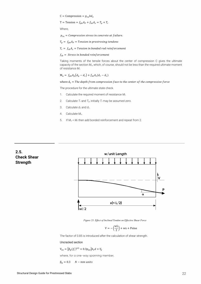
Figure 22. Ultimate State Stress Diagrams
2.4. Check Flexural Strength
Structural Design Guide for Prestressed Slabs 22
C Compression 𝑝 𝑏𝑑
T Tension 𝑓 𝐴 𝑓 𝐴 𝑇 𝑇
Where,
𝑝 𝐶𝑜𝑚𝑝𝑟𝑒𝑠𝑠𝑖𝑣𝑒 𝑠𝑡𝑟𝑒𝑠𝑠 𝑖𝑛 𝑐𝑜𝑛𝑐𝑟𝑒𝑡𝑒 𝑎𝑡 𝑓𝑎𝑖𝑙𝑢𝑟𝑒.
𝑇 𝑓 𝐴 𝑇𝑒𝑛𝑠𝑖𝑜𝑛 𝑖𝑛 𝑝𝑟𝑒𝑠𝑡𝑟𝑒𝑠𝑖𝑛𝑔 𝑡𝑒𝑛𝑑𝑜𝑛𝑠
𝑇 𝑓 𝐴 𝑇𝑒𝑛𝑠𝑖𝑜𝑛 𝑖𝑛 𝑏𝑜𝑛𝑑𝑒𝑑 𝑟𝑜𝑑 𝑟𝑒𝑖𝑛𝑓𝑜𝑟𝑐𝑒𝑚𝑒𝑛𝑡
𝑓 𝑆𝑡𝑟𝑒𝑠𝑠 𝑖𝑛 𝑏𝑜𝑛𝑑𝑒𝑑 𝑟𝑒𝑖𝑛𝑓𝑜𝑟𝑐𝑒𝑚𝑒𝑛𝑡
Taking moments of the tensile forces about the center of compression C gives the ultimate capacity of the section Mu, which, of course, should not be less than the required ultimate moment of resistance Mr.
M 𝑓 𝐴 𝑑 𝑑 𝑓 𝐴 𝑑 𝑑
where d 𝑇ℎ𝑒 𝑑𝑒𝑝𝑡ℎ 𝑓𝑟𝑜𝑚 𝑐𝑜𝑚𝑝𝑟𝑒𝑠𝑠𝑖𝑜𝑛 𝑓𝑎𝑐𝑒 𝑡𝑜 𝑡ℎ𝑒 𝑐𝑒𝑛𝑡𝑒𝑟 𝑜𝑓 𝑡ℎ𝑒 𝑐𝑜𝑚𝑝𝑟𝑒𝑠𝑠𝑖𝑣𝑒 𝑓𝑜𝑟𝑐𝑒
The procedure for the ultimate state check.
1. Calculate the required moment of resistance Mr.
2. Calculate Tr and Tp, initially Tr may be assumed zero.
3. Calculate dx and dc.
4. Calculate Mu.
5. If Mu < Mr then add bonded reinforcement and repeat from 2.
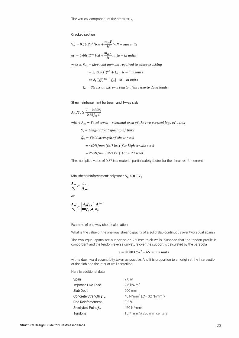
Figure 23. Effect of Inclined Tendon on Effective Shear Force
VwL2
wx Psinα
The factor of 0.85 is introduced after the calculation of shear strength.
Uncracked section
V β 𝑓 . 0.3𝑝 𝑏 𝑑 𝑉
where, for a one-way spanning member,
β 0.3 𝑁 𝑚𝑚 𝑢𝑛𝑖𝑡𝑠
2.5. Check Shear Strength
Structural Design Guide for Prestressed Slabs 23
The vertical component of the prestres, 𝑉
Cracked section
V 0.05 f . 𝑏 𝑑𝑚 𝑉
𝑀𝑖𝑛 𝑁 𝑚𝑚 𝑢𝑛𝑖𝑡𝑠
or 0.60 f . 𝑏 𝑑𝑚 𝑉
𝑀𝑖𝑛 1𝑏 𝑖𝑛 𝑢𝑛𝑖𝑡𝑠
where, M 𝐿𝑖𝑣𝑒 𝑙𝑜𝑎𝑑 𝑚𝑜𝑚𝑒𝑛𝑡 𝑟𝑒𝑞𝑢𝑖𝑟𝑒𝑑 𝑡𝑜 𝑐𝑎𝑢𝑠𝑒 𝑐𝑟𝑎𝑐𝑘𝑖𝑛𝑔
𝑍 0.5 𝑓 . 𝑓 𝑁 𝑚𝑚 𝑢𝑛𝑖𝑡𝑠
𝑜𝑟 𝑍 𝑓 . 𝑓 1𝑏 𝑖𝑛 𝑢𝑛𝑖𝑡𝑠
f 𝑆𝑡𝑟𝑒𝑠𝑠 𝑎𝑡 𝑒𝑥𝑡𝑟𝑒𝑚𝑒 𝑡𝑒𝑛𝑠𝑖𝑜𝑛 𝑓𝑖𝑏𝑟𝑒 𝑑𝑢𝑒 𝑡𝑜 𝑑𝑒𝑎𝑑 𝑙𝑜𝑎𝑑𝑠
Shear reinforcement for beam and 1-way slab
A /S𝑉 0.85𝑉0.85𝑓 𝑑
where A 𝑇𝑜𝑡𝑎𝑙 𝑐𝑟𝑜𝑠𝑠 𝑠𝑒𝑐𝑡𝑖𝑜𝑛𝑎𝑙 𝑎𝑟𝑒𝑎 𝑜𝑓 𝑡ℎ𝑒 𝑡𝑤𝑜 𝑣𝑒𝑟𝑡𝑖𝑐𝑎𝑙 𝑙𝑒𝑔𝑠 𝑜𝑓 𝑎 𝑙𝑖𝑛𝑘
𝑆 𝐿𝑜𝑛𝑔𝑖𝑡𝑢𝑑𝑖𝑛𝑎𝑙 𝑠𝑝𝑎𝑐𝑖𝑛𝑔 𝑜𝑓 𝑙𝑖𝑛𝑘𝑠
𝑓 𝑌𝑖𝑒𝑙𝑑 𝑠𝑡𝑟𝑒𝑛𝑔𝑡ℎ 𝑜𝑓 𝑠ℎ𝑒𝑎𝑟 𝑠𝑡𝑒𝑒𝑙
460𝑁/𝑚𝑚 66.7 𝑘𝑠𝑖 𝑓𝑜𝑟 ℎ𝑖𝑔ℎ 𝑡𝑒𝑛𝑠𝑖𝑙𝑒 𝑠𝑡𝑒𝑒𝑙
250𝑁/𝑚𝑚 36.3 𝑘𝑠𝑖 𝑓𝑜𝑟 𝑚𝑖𝑙𝑑 𝑠𝑡𝑒𝑒𝑙
The multiplied value of 0.87 is a material partial safety factor for the shear reinforcement.
Min. shear reinforcement: only when 𝐕𝐮 𝟎. 𝟓𝑽𝒄
𝐀𝐬𝐯
𝑺𝒗
𝒃𝒗
𝟑𝒇𝒚𝒗
𝐨𝐫
𝐀𝐬𝐯
𝑺𝒗
𝑨𝒑𝒇𝒑𝒖
𝟖𝟎𝒇𝒚𝒗𝒅𝒅𝒃𝒗
𝟎.𝟓
Example of one-way shear calculation
What is the value of the one-way shear capacity of a solid slab continuous over two equal spans?
The two equal spans are supported on 250mm thick walls. Suppose that the tendon profile is concordant and the tendon reverse curvature over the support is calculated by the parabola
e 0.000375x 65 𝑖𝑛 𝑚𝑚 𝑢𝑛𝑖𝑡𝑠
with a downward eccentricity taken as positive. And it is proportion to an origin at the intersection of the slab and the interior wall centerline.
Here is additional data:
Span 9.0 m
Imposed Live Load 2.5 kN/m2
Slab Depth 200 mm
Concrete Strength 𝒇𝒄𝒖 40 N/mm2 (𝑓 = 32 N/mm2)
Rod Reinforcement 0.2 %
Steel yield Point 𝒇𝒚 460 N/mm2
Tendons 15.7 mm @ 300 mm centers
Structural Design Guide for Prestressed Slabs 24
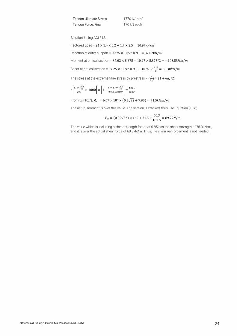
Tendon Ultimate Stress 1770 N/mm2
Tendon Force, Final 170 kN each
Solution: Using ACI 318.
Factored Load = 24 1.4 0.2 1.7 2.5 10.97kN/m
Reaction at outer support = 0.375 10.97 9.0 37.02kN/m
Moment at critical section = 37.02 8.875 10.97 8.875 2 103.5𝑘𝑁𝑚/𝑚
Shear at critical section = 0.625 10.97 9.0 10.97 . 60.30𝑘𝑁/𝑚
The stress at the extreme fibre stress by prestress = 1 eA /𝑍)
= . 1000 1 .
.
.
From Eq (10.7), M 6.67 10 0.5√32 7.90 71.5𝑘𝑁𝑚/𝑚
The actual moment is over this value. The section is cracked, thus use Equation (10.6)
V 0.05√32 165 71.560.3
103.589.7𝑘𝑁/𝑚
The value which is including a shear strength factor of 0.85 has the shear strength of 76.3kN/m, and it is over the actual shear force of 60.3kN/m. Thus, the shear reinforcement is not needed.
Chapter 3
Post-Tension Design Tip & Example
Post-Tension Design Tip & Example
Chapter 3
Structural Design Guide for Prestressed Slabs 25
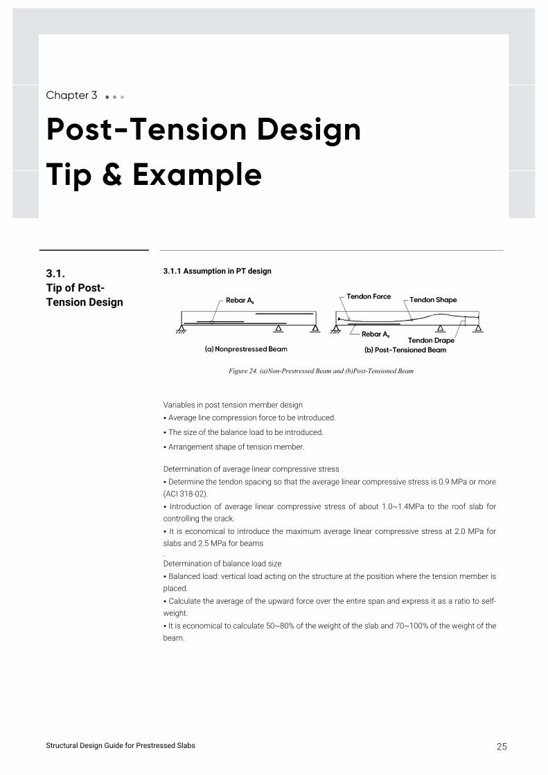
3.1.1 Assumption in PT design
Figure 24. (a)Non-Prestressed Beam and (b)Post-Tensioned Beam
Variables in post tension member design
• Average line compression force to be introduced.
• The size of the balance load to be introduced.
• Arrangement shape of tension member.
Determination of average linear compressive stress
• Determine the tendon spacing so that the average linear compressive stress is 0.9 MPa or more
(ACI 318-02).
• Introduction of average linear compressive stress of about 1.0~1.4MPa to the roof slab for
controlling the crack.
• It is economical to introduce the maximum average linear compressive stress at 2.0 MPa for
slabs and 2.5 MPa for beams . Determination of balance load size
• Balanced load: vertical load acting on the structure at the position where the tension member is
placed.
• Calculate the average of the upward force over the entire span and express it as a ratio to self-
weight.
• It is economical to calculate 50~80% of the weight of the slab and 70~100% of the weight of the
beam.
3.1. Tip of Post- Tension Design
Structural Design Guide for Prestressed Slabs 26
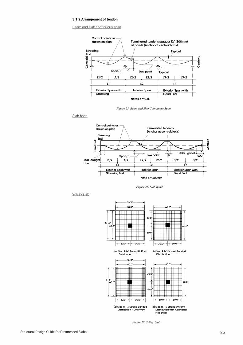
3.1.2 Arrangement of tendon
Beam and slab continuous span
Figure 25. Beam and Slab Continuous Span
Slab band
Figure 26. Slab Band
2-Way slab
Figure 27. 2-Way Slab
Structural Design Guide for Prestressed Slabs 27
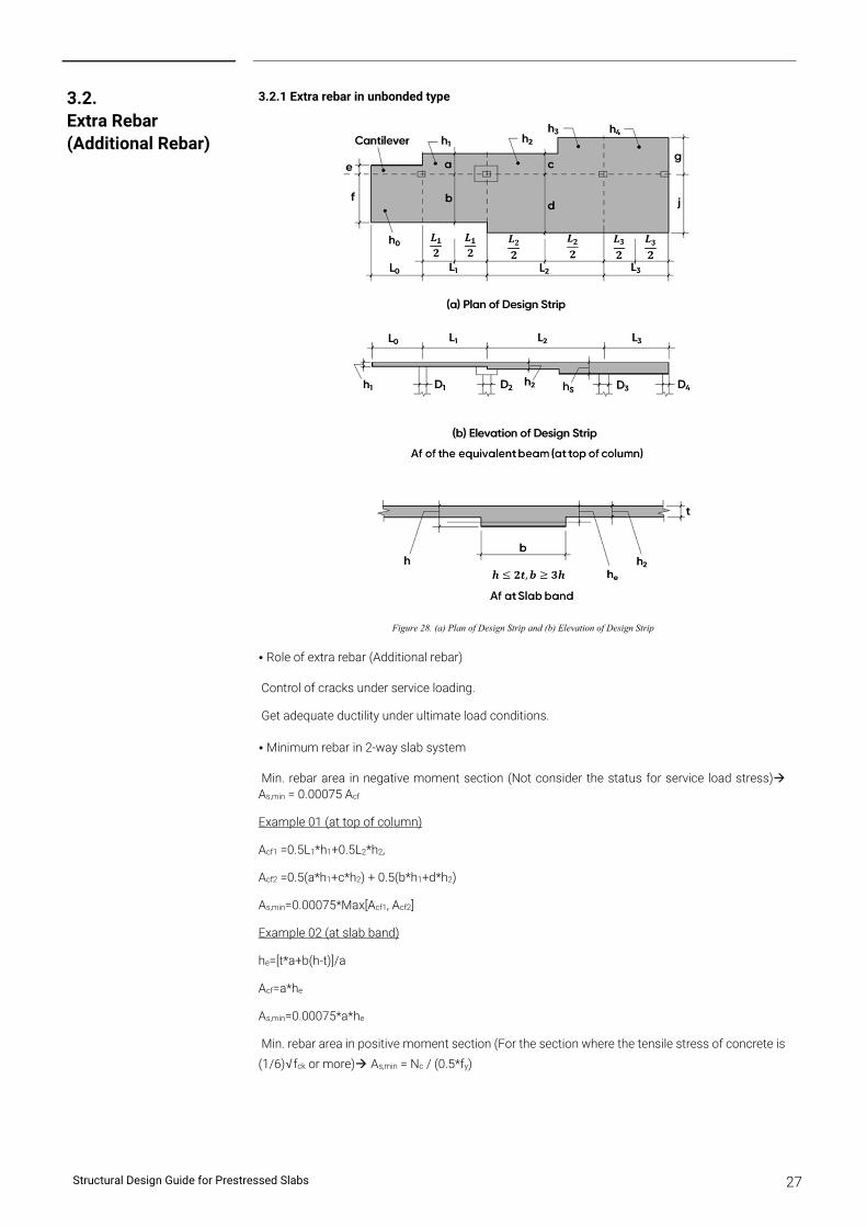
3.2.1 Extra rebar in unbonded type
Figure 28. (a) Plan of Design Strip and (b) Elevation of Design Strip
• Role of extra rebar (Additional rebar)
Control of cracks under service loading.
Get adequate ductility under ultimate load conditions.
• Minimum rebar in 2-way slab system
Min. rebar area in negative moment section (Not consider the status for service load stress) As,min = 0.00075 Acf
Example 01 (at top of column)
Acf1 =0.5L1*h1+0.5L2*h2,
Acf2 =0.5(a*h1+c*h2) + 0.5(b*h1+d*h2)
As,min=0.00075*Max[Acf1, Acf2]
Example 02 (at slab band)
he=[t*a+b(h-t)]/a
Acf=a*he
As,min=0.00075*a*he
Min. rebar area in positive moment section (For the section where the tensile stress of concrete is
(1/6)√fck or more) As,min = Nc / (0.5*fy)
3.2. Extra Rebar (Additional Rebar)
Structural Design Guide for Prestressed Slabs 28
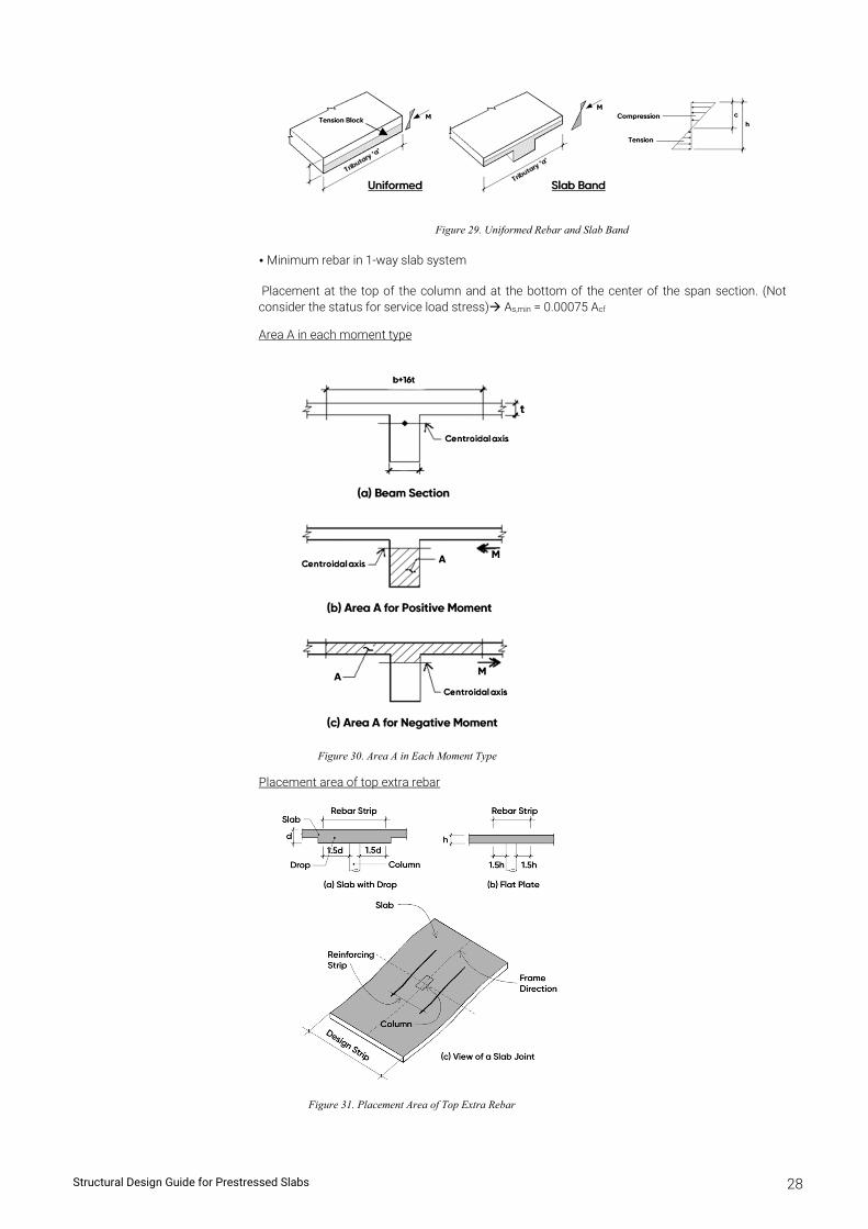
Figure 29. Uniformed Rebar and Slab Band
• Minimum rebar in 1-way slab system
Placement at the top of the column and at the bottom of the center of the span section. (Not consider the status for service load stress) As,min = 0.00075 Acf
Area A in each moment type
Figure 30. Area A in Each Moment Type
Placement area of top extra rebar
Figure 31. Placement Area of Top Extra Rebar
Structural Design Guide for Prestressed Slabs 29
Placement area of bottom extra rebar
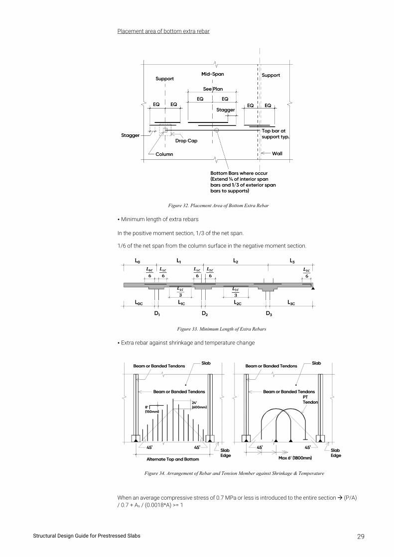
Figure 32. Placement Area of Bottom Extra Rebar
• Minimum length of extra rebars
In the positive moment section, 1/3 of the net span.
1/6 of the net span from the column surface in the negative moment section.
Figure 33. Minimum Length of Extra Rebars
• Extra rebar against shrinkage and temperature change
Figure 34. Arrangement of Rebar and Tension Member against Shrinkage & Temperature
When an average compressive stress of 0.7 MPa or less is introduced to the entire section (P/A) / 0.7 + As / (0.0018*A) >= 1
Structural Design Guide for Prestressed Slabs 30
3.2.2 Extra rebar in bonded type
• No extra rebars are required in the following cases:
When the post tension member satisfies the requirements of the design code under the service load condition.
When the post tension member satisfies the strength requirements.
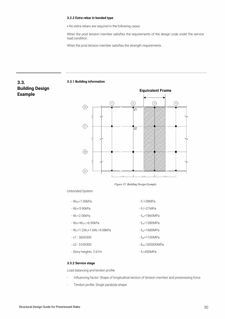
3.3.1 Building information
Figure 35. Building Design Example
Unbonded System
3.3.2 Service stage
Load balancing and tendon profile
- Influencing factor: Shape of longitudinal section of tension member and prestressing force
- Tendon profile: Single parabola shape
3.3. Building Design Example
- WSD=1.00kPa
- WD=3.90kPa
- WL=2.00kPa
- WW=WD+L=6.90kPa
- WU=1.2WD+1.6WL=9.08kPa
- c1 : 360X300
- c2 : 510X300
- Story heights: 2.67m
- fc’=28MPa
- fci’=21MPa
- fpu=1860MPa
- fps=1280MPa
- fpy=1680MPa
- fpe=1100MPa
- Eps=200000MPa
- fy=400MPa
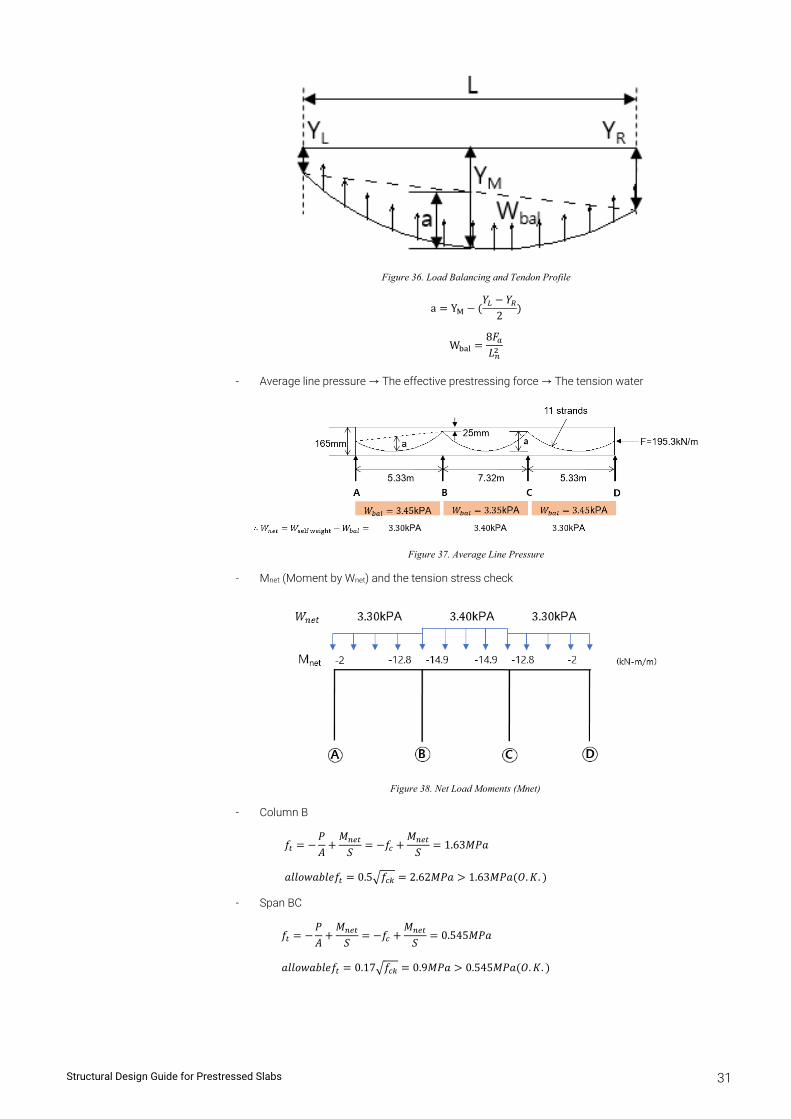
Structural Design Guide for Prestressed Slabs 31
Figure 36. Load Balancing and Tendon Profile
a Y𝑌 𝑌
2
W8𝐹𝐿
- Average line pressure → The effective prestressing force → The tension water
Figure 37. Average Line Pressure
- Mnet (Moment by Wnet) and the tension stress check
Figure 38. Net Load Moments (Mnet)
- Column B
𝑓𝑃𝐴
𝑀𝑆
𝑓𝑀
𝑆1.63𝑀𝑃𝑎
𝑎𝑙𝑙𝑜𝑤𝑎𝑏𝑙𝑒𝑓 0.5 𝑓 2.62𝑀𝑃𝑎 1.63𝑀𝑃𝑎 𝑂. 𝐾.
- Span BC
𝑓𝑃𝐴
𝑀𝑆
𝑓𝑀
𝑆0.545𝑀𝑃𝑎
𝑎𝑙𝑙𝑜𝑤𝑎𝑏𝑙𝑒𝑓 0.17 𝑓 0.9𝑀𝑃𝑎 0.545𝑀𝑃𝑎 𝑂. 𝐾.
Structural Design Guide for Prestressed Slabs 32
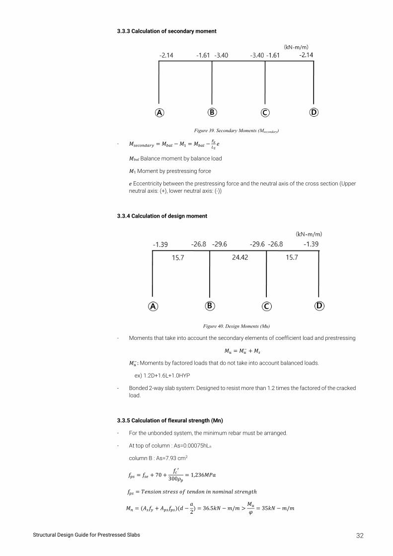
3.3.3 Calculation of secondary moment
Figure 39. Secondary Moments (Msecondary)
- 𝑀 𝑀 𝑀 𝑀 𝑒
𝑀𝑏𝑎𝑙 Balance moment by balance load
𝑀1 Moment by prestressing force
𝑒 Eccentricity between the prestressing force and the neutral axis of the cross section (Upper neutral axis: (+), lower neutral axis: (-))
3.3.4 Calculation of design moment
Figure 40. Design Moments (Mu)
- Moments that take into account the secondary elements of coefficient load and prestressing
𝑀 𝑀 𝑀
𝑀 : Moments by factored loads that do not take into account balanced loads.
ex) 1.2D+1.6L+1.0HYP
- Bonded 2-way slab system: Designed to resist more than 1.2 times the factored of the cracked load.
3.3.5 Calculation of flexural strength (Mn)
- For the unbonded system, the minimum rebar must be arranged.
- At top of column : As=0.00075hLn
column B : As=7.93 cm2
𝑓 𝑓 70𝑓 ′
300𝜌1,236𝑀𝑃𝑎
𝑓 𝑇𝑒𝑛𝑠𝑖𝑜𝑛 𝑠𝑡𝑟𝑒𝑠𝑠 𝑜𝑓 𝑡𝑒𝑛𝑑𝑜𝑛 𝑖𝑛 𝑛𝑜𝑚𝑖𝑛𝑎𝑙 𝑠𝑡𝑟𝑒𝑛𝑔𝑡ℎ
𝑀 𝐴 𝑓 𝐴 𝑓 𝑑𝑎2
36.5𝑘𝑁 𝑚/𝑚𝑀𝜑
35𝑘𝑁 𝑚/𝑚
Structural Design Guide for Prestressed Slabs 33
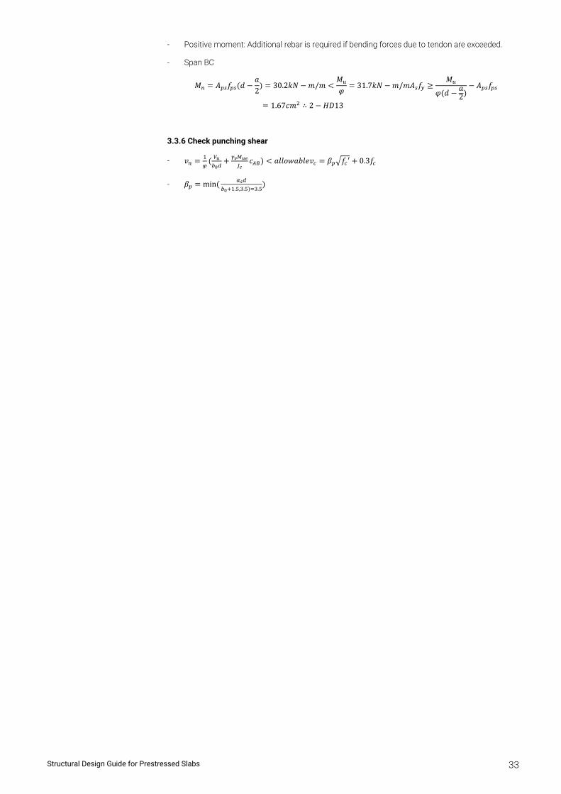
- Positive moment: Additional rebar is required if bending forces due to tendon are exceeded.
- Span BC
𝑀 𝐴 𝑓 𝑑𝑎2
30.2𝑘𝑁 𝑚/𝑚𝑀𝜑
31.7𝑘𝑁 𝑚/𝑚𝐴 𝑓𝑀
𝜑 𝑑 𝑎2
𝐴 𝑓
1.67𝑐𝑚 ∴ 2 𝐻𝐷13
3.3.6 Check punching shear
- 𝑣 𝑐 𝑎𝑙𝑙𝑜𝑤𝑎𝑏𝑙𝑒𝑣 𝛽 𝑓 ′ 0.3𝑓
- 𝛽 min. , . .
Chapter 4
Tutorial for Post-Tension Beam
Chapter 4
Tutorial for Post-Tension Beam
Structural Design Guide for Prestressed Slabs 34
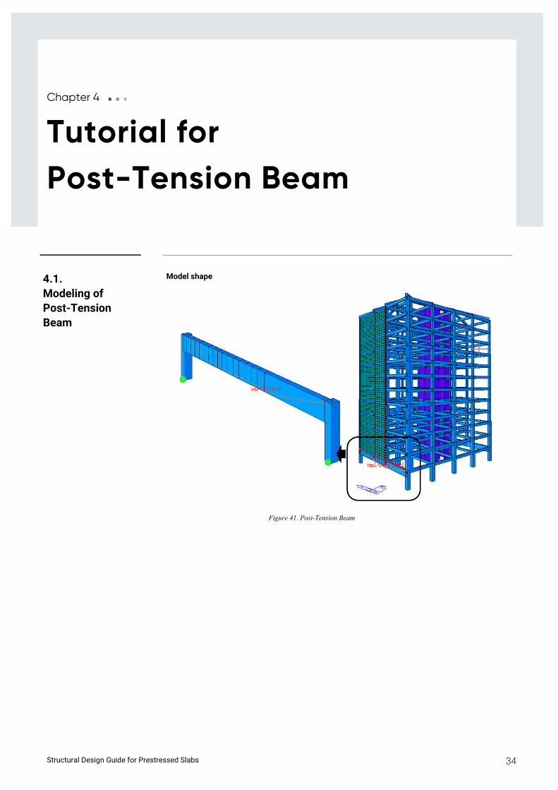
Model shape
Figure 41. Post-Tension Beam
4.1. Modeling of Post-Tension Beam
Structural Design Guide for Prestressed Slabs 35
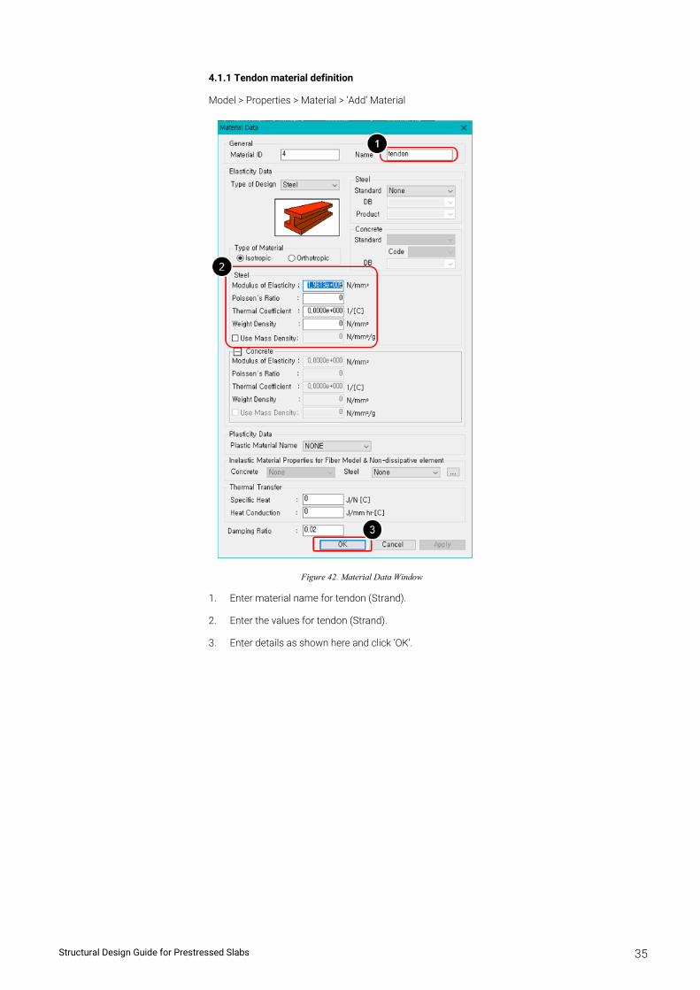
4.1.1 Tendon material definition
Model > Properties > Material > ‘Add’ Material
Figure 42. Material Data Window
1. Enter material name for tendon (Strand).
2. Enter the values for tendon (Strand).
3. Enter details as shown here and click ‘OK’.
Post-Tension Slab Analysis and Design 36
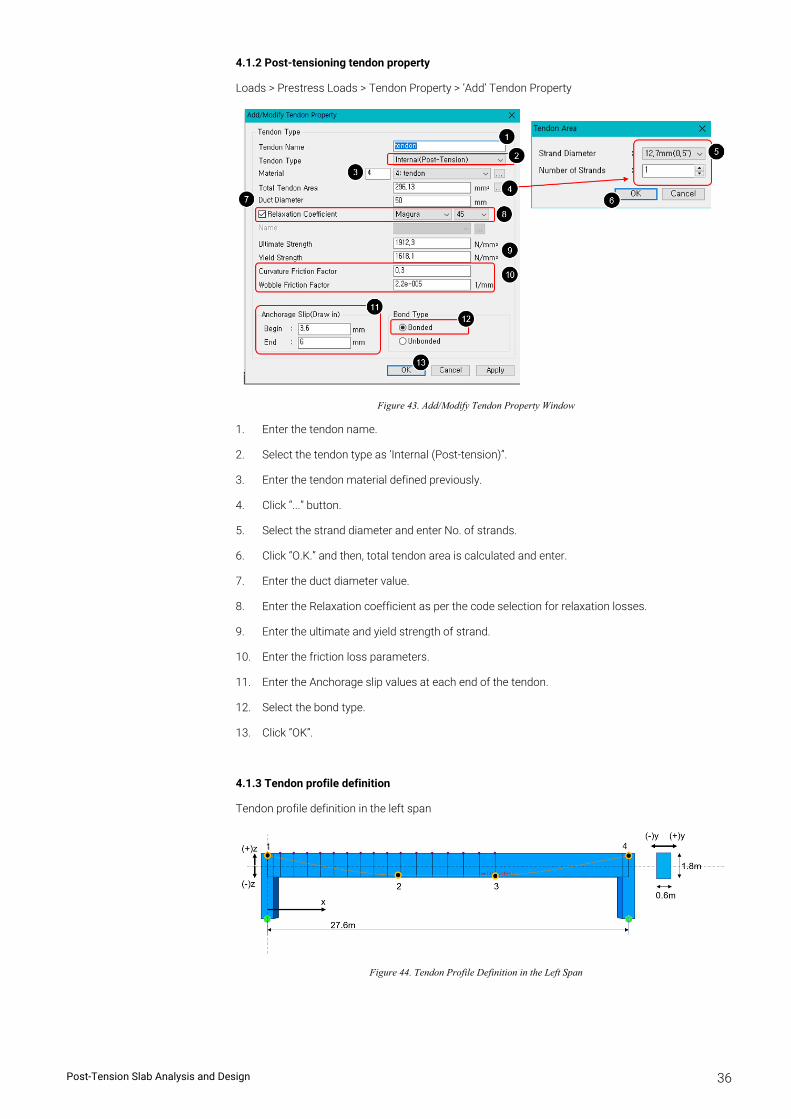
4.1.2 Post-tensioning tendon property
Loads > Prestress Loads > Tendon Property > ’Add’ Tendon Property
Figure 43. Add/Modify Tendon Property Window
1. Enter the tendon name.
2. Select the tendon type as ‘Internal (Post-tension)”.
3. Enter the tendon material defined previously.
4. Click “...” button.
5. Select the strand diameter and enter No. of strands.
6. Click “O.K.” and then, total tendon area is calculated and enter.
7. Enter the duct diameter value.
8. Enter the Relaxation coefficient as per the code selection for relaxation losses.
9. Enter the ultimate and yield strength of strand.
10. Enter the friction loss parameters.
11. Enter the Anchorage slip values at each end of the tendon.
12. Select the bond type.
13. Click “OK”.
4.1.3 Tendon profile definition
Tendon profile definition in the left span
Figure 44. Tendon Profile Definition in the Left Span
Post-Tension Slab Analysis and Design 37
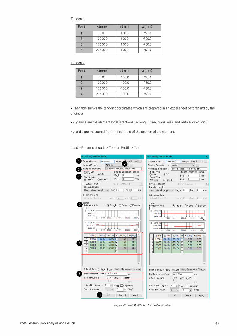
Tendon-1
Point x (mm) y (mm) z (mm)
1 0.0 100.0 750.0
2 10000.0 100.0 -750.0
3 17600.0 100.0 -750.0
4 27600.0 100.0 750.0
Tendon-2
Point x (mm) y (mm) z (mm)
1 0.0 -100.0 750.0
2 10000.0 -100.0 -750.0
3 17600.0 -100.0 -750.0
4 27600.0 -100.0 750.0
• The table shows the tendon coordinates which are prepared in an excel sheet beforehand by the
engineer.
• x, y and z are the element local directions i.e. longitudinal, transverse and vertical directions.
• y and z are measured from the centroid of the section of the element.
Load > Prestress Loads > Tendon Profile > ’Add’
Figure 45. Add/Modify Tendon Profile Window
Post-Tension Slab Analysis and Design 38
1. Enter the tendon profile name.
2. Select the tendon property for the post-tensioning tendon.
3. Select elements included to the beam member with post-tensioning tendon.
4. Select the tendon profile input type as 3D and the curve type as Spline.
5. Choose Tendon reference axis as “Straight” type.
6. Input the profile insertion point as center of beam member and select x-axis direction as “Y”(global axis).
7. Copy paste the coordinates x,y,z in the table from the excel sheet.
8. Click on OK after all the details shown in the figure.
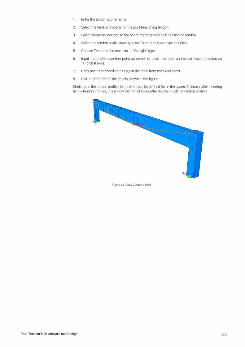
Similarly all the tendon profiles in the webs can be defined for all the spans. So finally after inserting all the tendon profiles, this is how the model looks after displaying all the tendon profiles
Figure 46. Final Tendon Model
Post-Tension Slab Analysis and Design 39
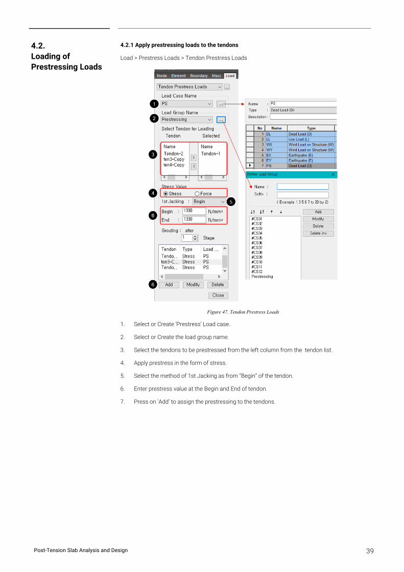
4.2.1 Apply prestressing loads to the tendons
Load > Prestress Loads > Tendon Prestress Loads
Figure 47. Tendon Prestress Loads
1. Select or Create ‘Prestress’ Load case.
2. Select or Create the load group name.
3. Select the tendons to be prestressed from the left column from the tendon list.
4. Apply prestress in the form of stress.
5. Select the method of 1st Jacking as from “Begin” of the tendon.
6. Enter prestress value at the Begin and End of tendon.
7. Press on ‘Add’ to assign the prestressing to the tendons.
4.2. Loading of Prestressing Loads
Post-Tension Slab Analysis and Design 40
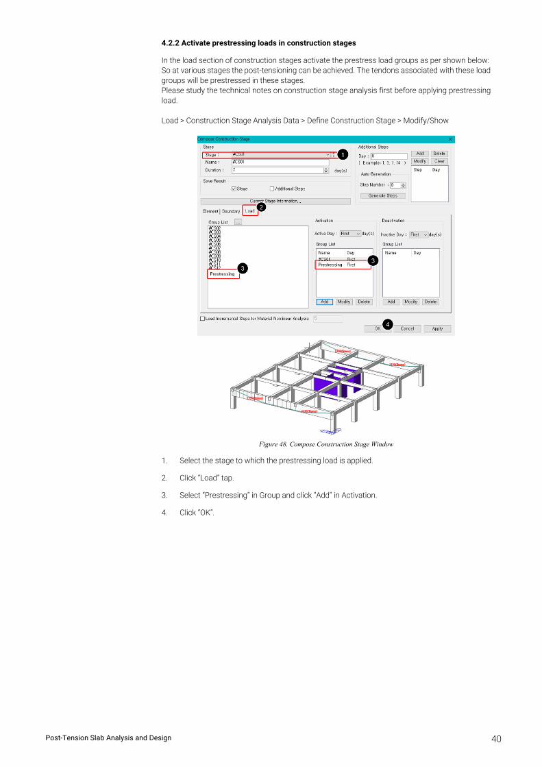
4.2.2 Activate prestressing loads in construction stages
In the load section of construction stages activate the prestress load groups as per shown below: So at various stages the post-tensioning can be achieved. The tendons associated with these load groups will be prestressed in these stages. Please study the technical notes on construction stage analysis first before applying prestressing load. Load > Construction Stage Analysis Data > Define Construction Stage > Modify/Show
Figure 48. Compose Construction Stage Window
1. Select the stage to which the prestressing load is applied.
2. Click “Load” tap.
3. Select “Prestressing” in Group and click “Add” in Activation.
4. Click “OK”.