Embed Size (px)
Citation preview
1
Structured light systems
Hiroshi Kawasaki & Ryusuke Sagawa
Tutorial 1: 9:00 to 12:00 Monday May 16 2011
Today
• Part I (Kawasaki@Kagoshima Univ.)– Calibration of Structured light systems
• Part II (Sagawa@AIST Japan)– Structured light systems for moving object
Structured light systems
2
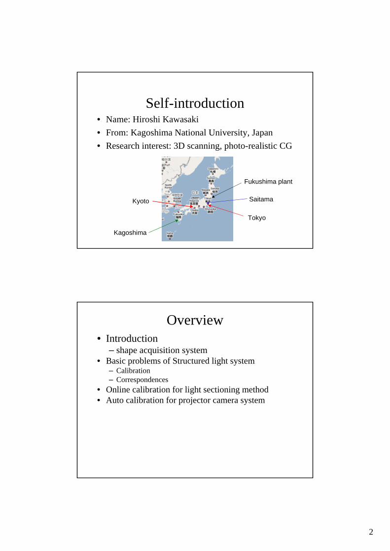
Self-introduction• Name: Hiroshi Kawasaki• From: Kagoshima National University, Japan• Research interest: 3D scanning, photo-realistic CG
Tokyo
Saitama
Kagoshima
Kyoto
Fukushima plant
Overview• Introduction
– shape acquisition system• Basic problems of Structured light system
– Calibration– Correspondences
• Online calibration for light sectioning method• Auto calibration for projector camera system

3
Overview• Introduction
– shape acquisition system• Basic problems of Structured light system
– Calibration– Correspondences
• Online calibration for light sectioning method• Auto calibration for projector camera system
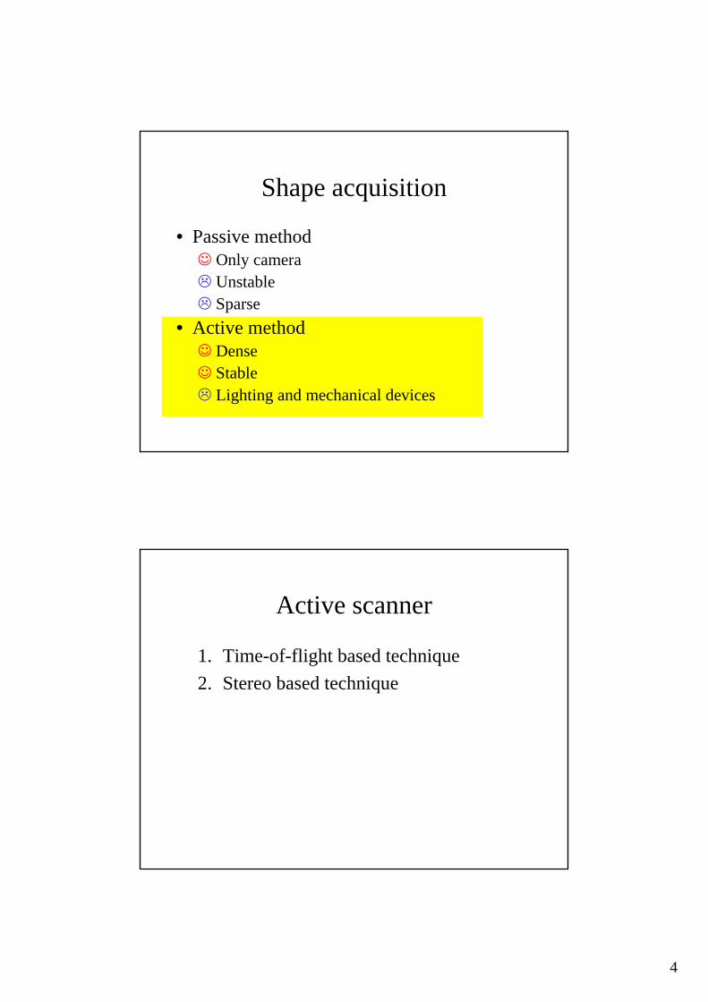
Shape acquisition
• Passive method☺ Only camera
UnstableSparse
• Active method☺ Dense☺ Stable
Lighting and mechanical devices
4
Shape acquisition
• Passive method☺ Only camera
UnstableSparse
• Active method☺ Dense☺ Stable
Lighting and mechanical devices
Active scanner
1. Time-of-flight based technique 2. Stereo based technique
5
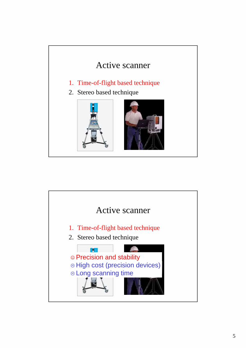
Active scanner
1. Time-of-flight based technique2. Stereo based technique
Active scanner
1. Time-of-flight based technique2. Stereo based technique
☺Precision and stabilityHigh cost (precision devices)Long scanning time

6
Active scanner
1. Time-of-flight based technique 2. Stereo based technique
Possibility of☺ cost efficiency☺ precision☺ short scanning time
by computer vision techniques
Stereo based active scan• Camera + point laser projector☺ Easy to make☺ Good accuracy
Slow
Camera
Observed laser point
•Triangulation

7
Stereo based active scan• Camera + line laser projector
– Light sectioning method – Simple algorithm
Camera
Observed laser line
Stereo based active scan
ProjectorCamera
Target object
• Camera + video projector – Projector camera system– Fast– Stereo
8
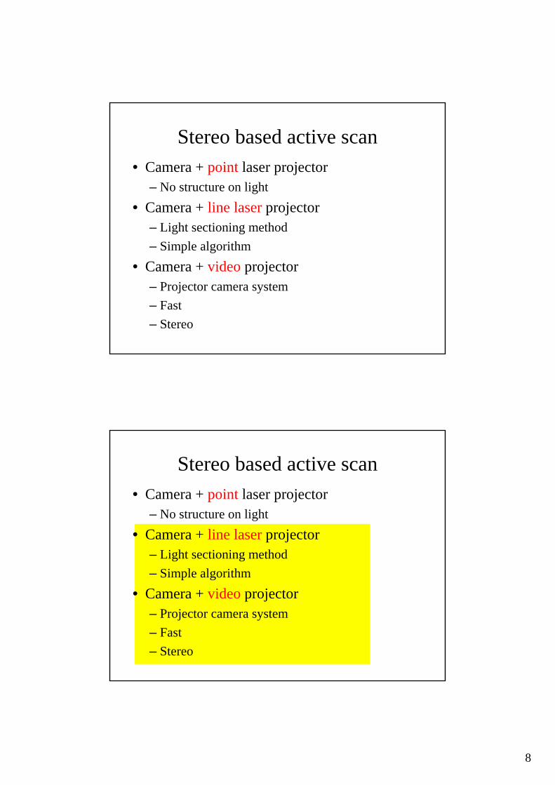
Stereo based active scan• Camera + point laser projector
– No structure on light• Camera + line laser projector
– Light sectioning method – Simple algorithm
• Camera + video projector – Projector camera system– Fast– Stereo
Stereo based active scan• Camera + point laser projector
– No structure on light• Camera + line laser projector
– Light sectioning method – Simple algorithm
• Camera + video projector – Projector camera system– Fast– Stereo

9
Overview• Introduction
– shape acquisition system• Basic problems of Structured light system
– Calibration– Correspondences
• Online calibration for light sectioning method• Auto calibration for projector camera system
Basic problems of Structured light system
• Calibration of structured light• Correspondences

10
Basic problems of Structured light system
• Calibration of structured light• Correspondences Part II
Part I
Calibration of structured light
• Calibration of light source (Intrinsic)• Calibration between light source and
camera (Extrinsic)
11
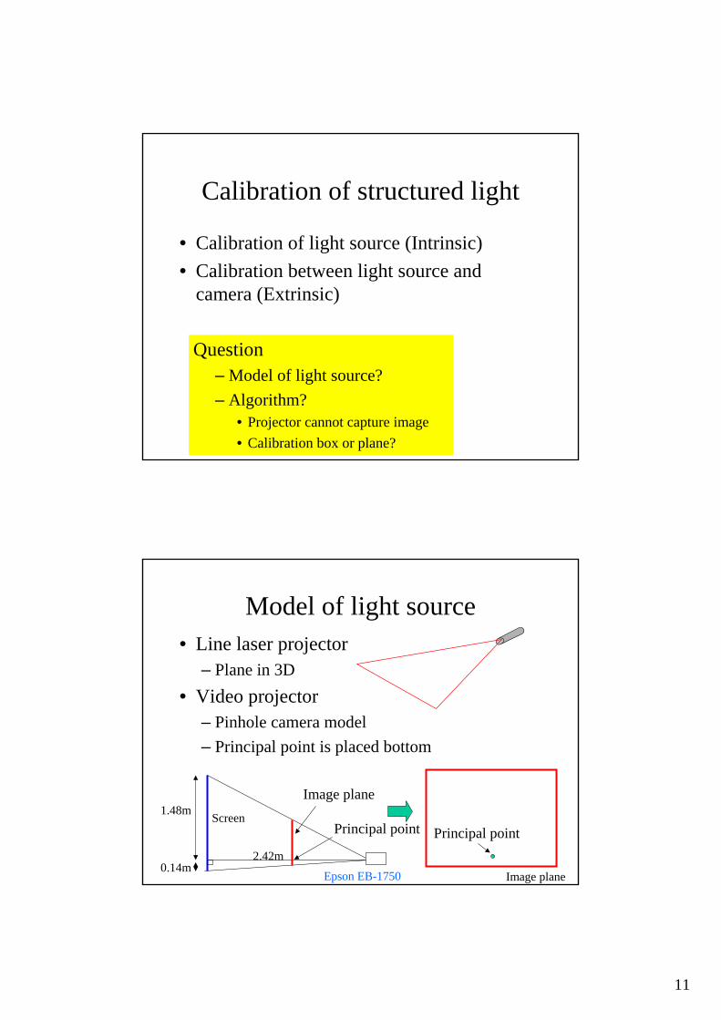
Calibration of structured light
• Calibration of light source (Intrinsic)• Calibration between light source and
camera (Extrinsic)
Question– Model of light source?– Algorithm?
• Projector cannot capture image• Calibration box or plane?
Model of light source• Line laser projector
– Plane in 3D • Video projector
– Pinhole camera model– Principal point is placed bottom
0.14m
1.48m
2.42m
Screen
Image plane
Image plane
Principal point Principal point
Epson EB-1750

12
Basic approach
• Using calibration object
Video projector
Coded pattern sequence
Line laser projector
Calibration of laser plane• Light sectioning method (triangulation)• Estimate laser plane parameters from observed
curves
Camera
Laser plane (ax+by+cz=1)
Observed laser line

13
Calibration of projector camera system• Stereo method• Estimate camera parameter
camera2camera1Projector
Estimation of 6 params•Rot:3+Trans:3
Example of calibration[projector calibration toolbox]
Complicated and unstable process
14
Overview• Introduction
– shape acquisition system• Basic problems of Structured light system
– Calibration– Correspondences
• Online calibration for light sectioning method• Auto calibration for projector camera system
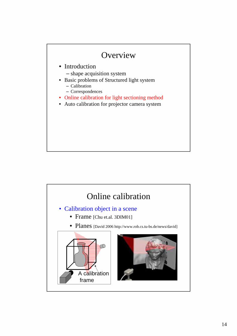
Online calibration
• Frame [Chu et.al. 3DIM01]
• Planes [David 2006 http://www.rob.cs.tu-bs.de/news/david]
A calibrationframe
• Calibration object in a scene
15
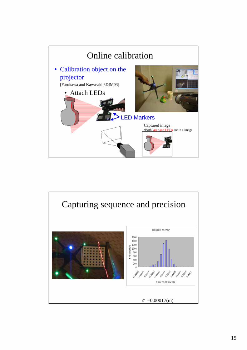
Online calibration• Calibration object on the
projector [Furukawa and Kawasaki 3DIM03]
LED Markers
• Attach LEDs
Captured image•Both laser and LEDs are in a image
Capturing sequence and precision
Histgram of error
0200400
60080010001200
14001600
-0.0009
-0.0007
-0.0005
-0.0003
-0.0001
0.0001
0.0003
0.0005
0.0007
0.0009
0.0011
Error of distance[m]
Frequency
σ=0.00017(m)
16
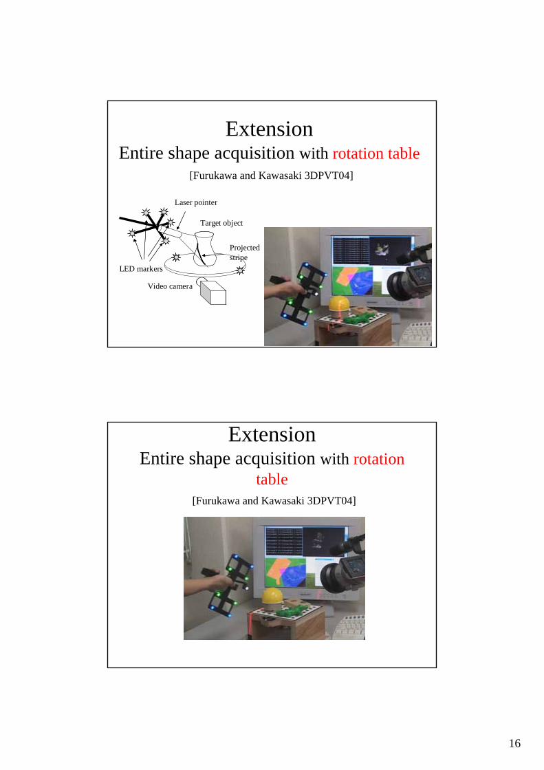
ExtensionEntire shape acquisition with rotation table
[Furukawa and Kawasaki 3DPVT04]
LED markers
Laser pointer
Video camera
Target object
Projectedstripe
ExtensionEntire shape acquisition with rotation
table[Furukawa and Kawasaki 3DPVT04]

17
Rotation table results
Previous method• Pre-calibration△ Hard calibration (fixed system)△ Use motor and precision devices
• Online-calibration△ Frames or planes are required [david’06]
△ LED markers required [kawasaki’03]
Can we eliminate all additional devices ?

18
Self-calibration of laser plane
Single camera
Captured image
without any additional devices
System configuration
Problem 1• Can we reconstruct shape from the
following image?
NO!

19
Problem 2• How about this?
Maybe?
Example of line laser projector(cross pattern by two lasers)
20
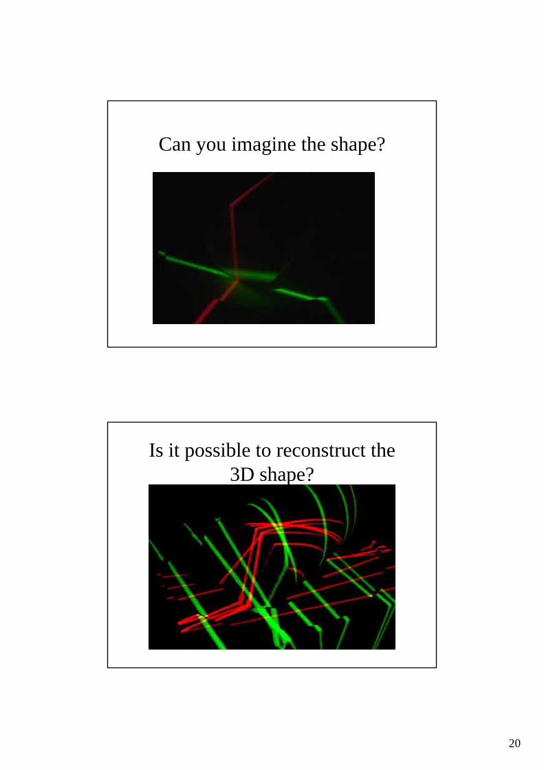
Can you imagine the shape?
Is it possible to reconstruct the 3D shape?
21
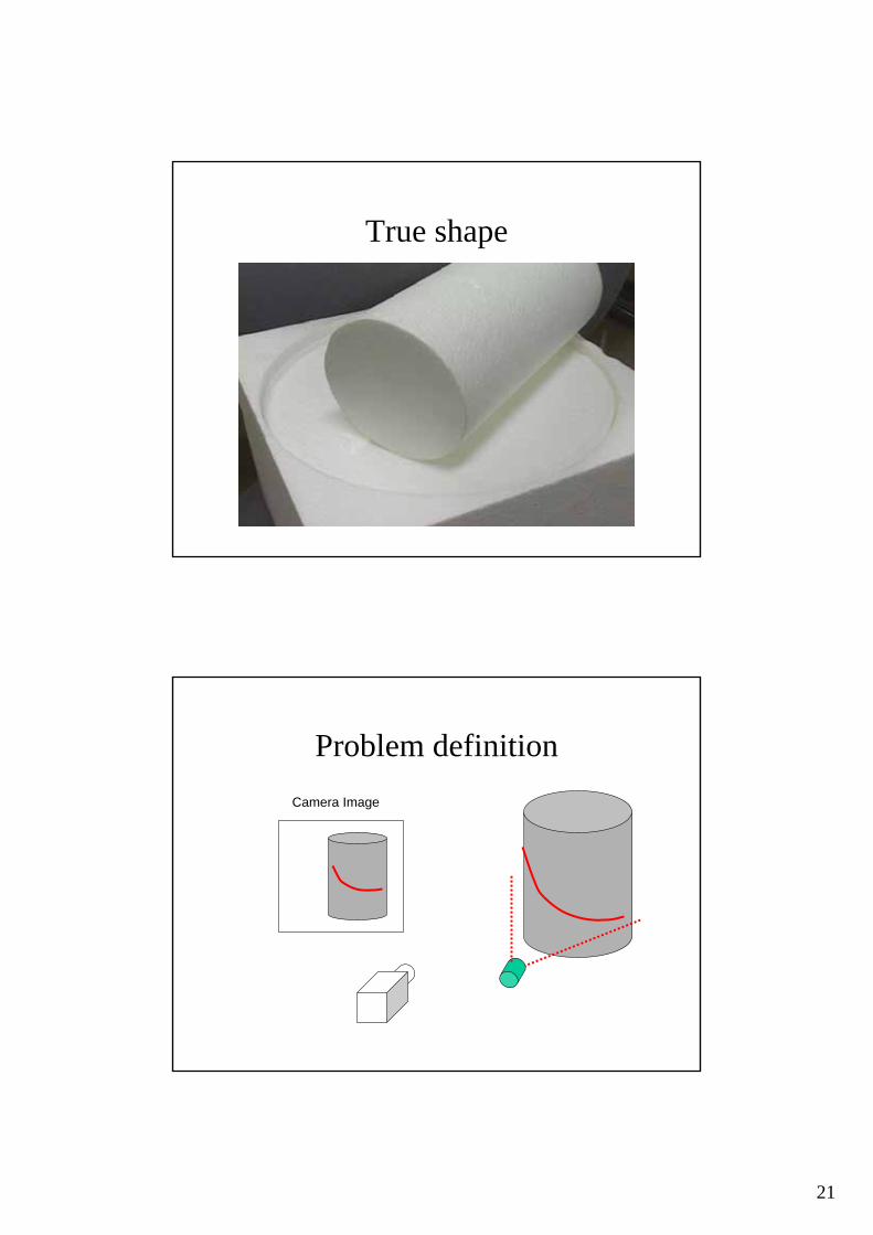
True shape
Problem definitionCamera Image
22
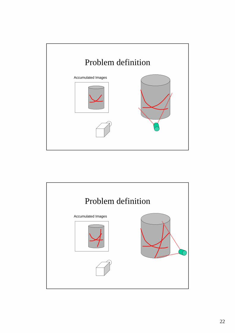
Problem definitionAccumulated Images
Problem definitionAccumulated Images
23
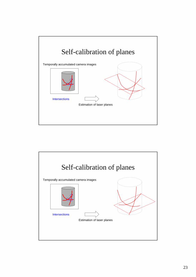
Self-calibration of planesTemporally accumulated camera images
Intersections
Estimation of laser planes
Self-calibration of planes
Intersections
Estimation of laser planes
Temporally accumulated camera images
24
Self-calibration of planes
Intersections
Estimation of laser planes
Temporally accumulated camera images
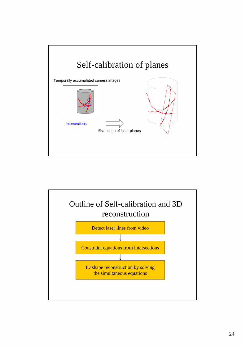
Outline of Self-calibration and 3D reconstruction
Detect laser lines from video
Constraint equations from intersections
3D shape reconstruction by solving the simultaneous equations
25
Outline of Self-calibration and 3D reconstruction
Detect laser lines from video
Constraint equations from intersections
3D shape reconstruction by solving the simultaneous equations
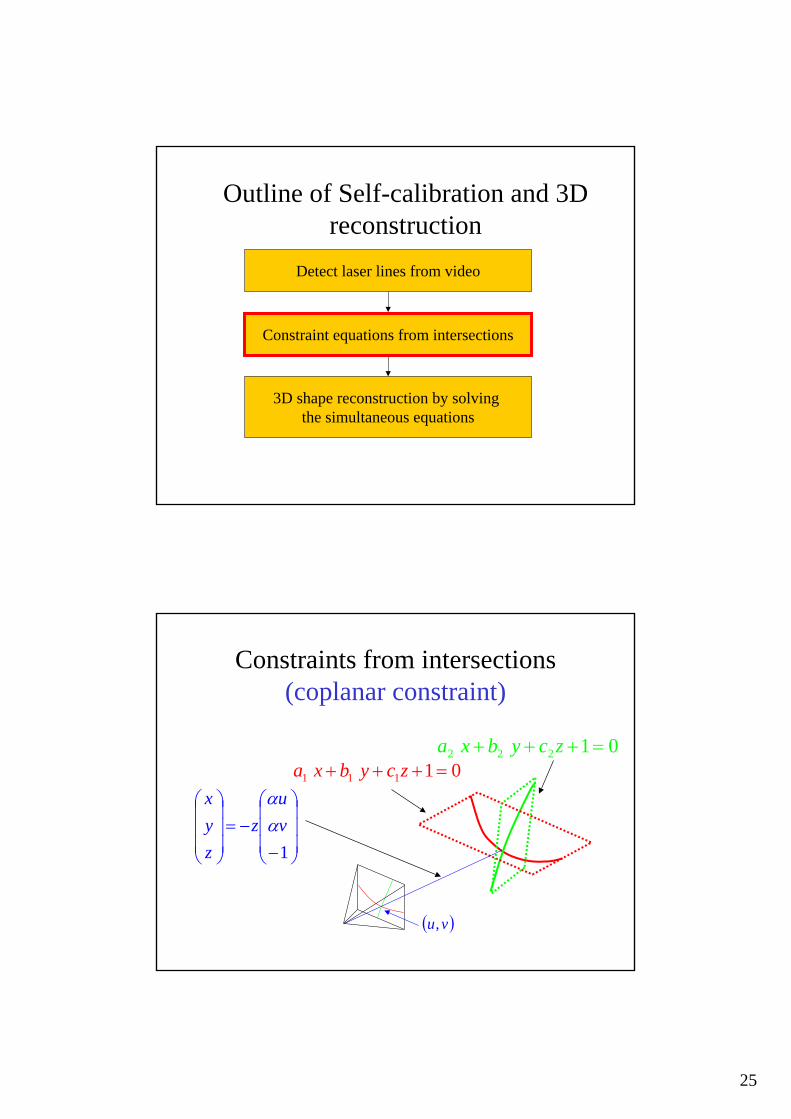
Constraints from intersections(coplanar constraint)
( )vu,
01111 =+++ zcybxa01222 =+++ zcybxa
⎟⎟⎟
⎠
⎞
⎜⎜⎜
⎝
⎛
−−=
⎟⎟⎟
⎠
⎞
⎜⎜⎜
⎝
⎛
1vu
zzyx
αα
26
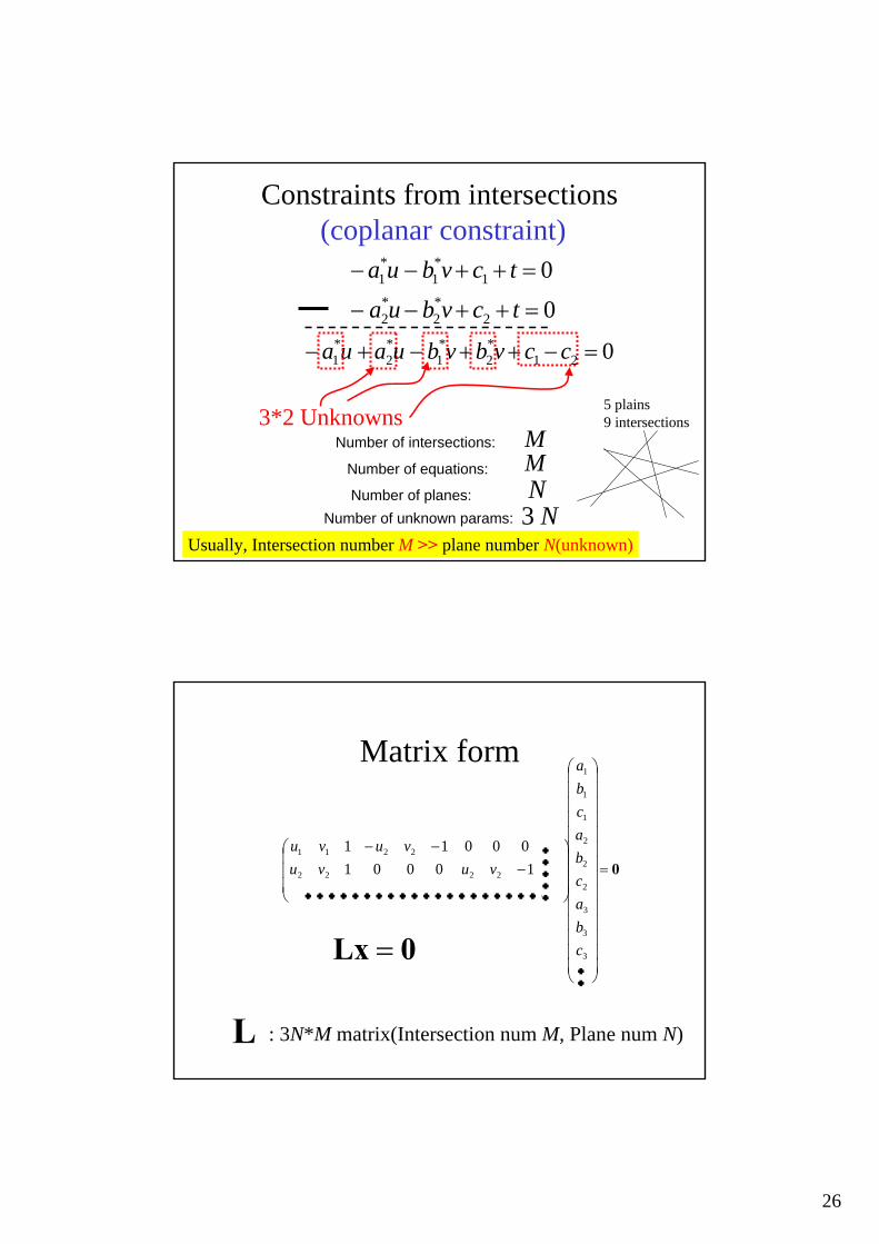
Constraints from intersections(coplanar constraint)
3*2 Unknowns
0
0
2*2
*2
1*1
*1
=++−−
=++−−
tcvbua
tcvbua
021*2
*1
*2
*1 =−++−+− ccvbvbuaua
MNumber of intersections:
Number of equations:
Number of planes: NNumber of unknown params: N3
Usually, Intersection number M >> plane number N(unknown)
5 plains9 intersections
M
Matrix form
0=
⎟⎟⎟⎟⎟⎟⎟⎟⎟⎟⎟⎟⎟⎟
⎠
⎞
⎜⎜⎜⎜⎜⎜⎜⎜⎜⎜⎜⎜⎜⎜
⎝
⎛
⎟⎟⎟
⎠
⎞
⎜⎜⎜
⎝
⎛−
−−
M
OMMMMMMMMM
L
L
3
3
3
2
2
2
1
1
1
2222
2211
1000100011
cbacbacba
vuvuvuvu
0Lx =
L : 3N*M matrix(Intersection num M, Plane num N)
・・・・・・・・・・・・・・・・・・・・・
・・・・・
・・

27
Reconstruction from coplanarity0Lx =
has 4 degrees of freedomxSolution
3D homographyPreserve coplanarity
(Projective reconstruction)
The 4 DOFs Found in other research areas. e.g. ● Polyhedra analyses in single view reconstruction● Generalized Bas-Relief Ambiguity in photometric stereo
Shape from coplanarityL
0xVΣΣ
U 2
1
=⎟⎟⎟
⎠
⎞
⎜⎜⎜
⎝
⎛⊥
000
0
1Σ 2Σ Square diagonal matrix
4 columns3n-4
(if no errors)0Σ2 ≈
Sort eigen values after SVD of
28
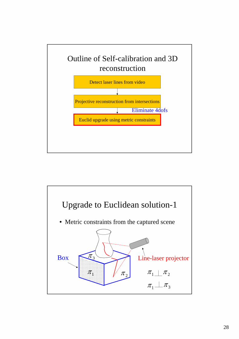
Outline of Self-calibration and 3D reconstruction
Detect laser lines from video
Projective reconstruction from intersections
Euclid upgrade using metric constraints
Eliminate 4dofs
Upgrade to Euclidean solution-1
• Metric constraints from the captured scene
Box Line-laser projector
1π 2π
3π
1π 2π
1π 3π
29
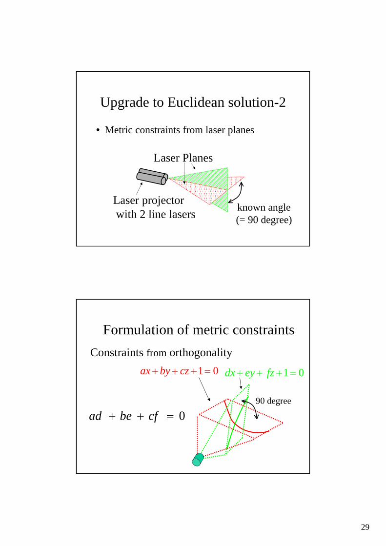
Upgrade to Euclidean solution-2
• Metric constraints from laser planes
Laser projectorwith 2 line lasers
Laser Planes
known angle(= 90 degree)
Formulation of metric constraints
01=+++ czbyax 01=+++ fzeydx
90 degree
0=++ cfbead
Constraints from orthogonality

30
Upgrade to Euclidean solution-3
• Another metric constraints from laser planes
Laser projectorwith 2 line lasers
Laser Planes
parallel
Formulation of metric constraints
0),,(),,( =⊗ fedcba
Constraints of parallelism01=+++ czbyax
01=+++ fzeydx
31
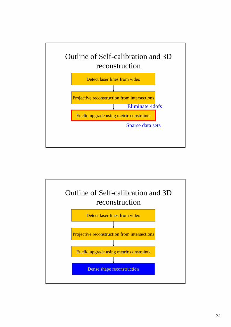
Outline of Self-calibration and 3D reconstruction
Detect laser lines from video
Projective reconstruction from intersections
Euclid upgrade using metric constraints
Eliminate 4dofs
Sparse data sets
Outline of Self-calibration and 3D reconstruction
Detect laser lines from video
Dense shape reconstruction
Projective reconstruction from intersections
Euclid upgrade using metric constraints
32
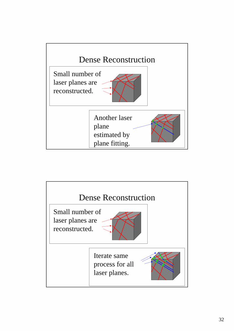
Dense ReconstructionSmall number of laser planes are reconstructed.
Another laser planeestimated by plane fitting.
Dense ReconstructionSmall number of laser planes are reconstructed.
Iterate same process for all laser planes.

33
Experiments
• Simulation data• Real data
Simulation data 1• Randomly project single line laser
20 lasers and 200 intersections
Require 3 metric constraints for Euclidean solution up to scale
34
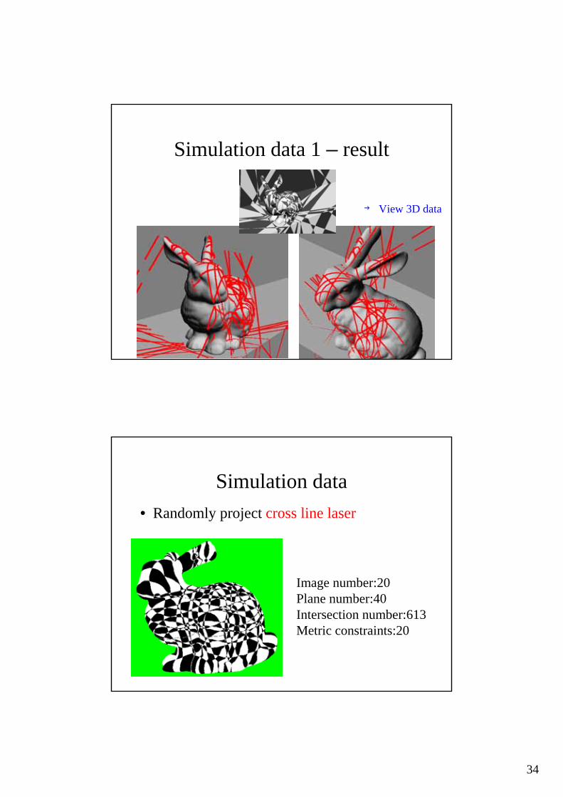
Simulation data 1 – result
→ View 3D data
Simulation data
Image number:20Plane number:40Intersection number:613Metric constraints:20
• Randomly project cross line laser

35
Simulation data – result
→ View 3D data
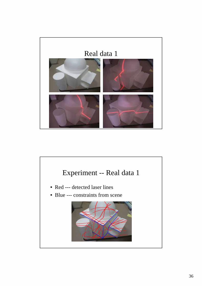
Experiment -- Real data 1• Single line laser
36
Real data 1
Experiment -- Real data 1
• Red --- detected laser lines• Blue --- constraints from scene

37
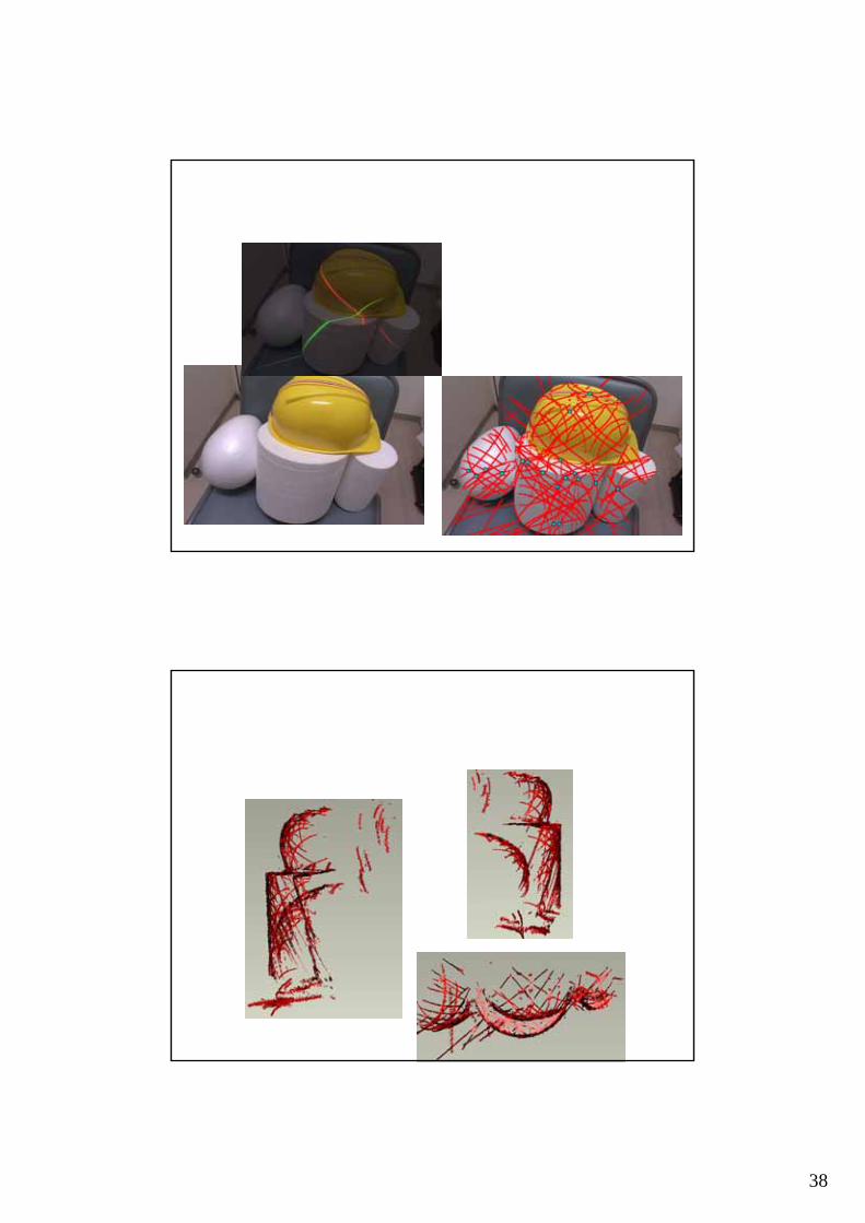
Real data 1
Experiment -- Real data 2• Cross line laser
38
39
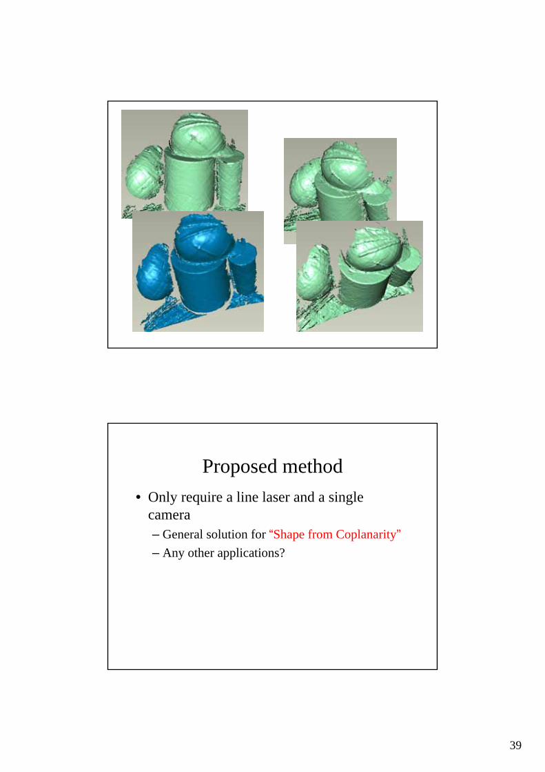
Proposed method• Only require a line laser and a single
camera– General solution for “Shape from Coplanarity”– Any other applications?
40
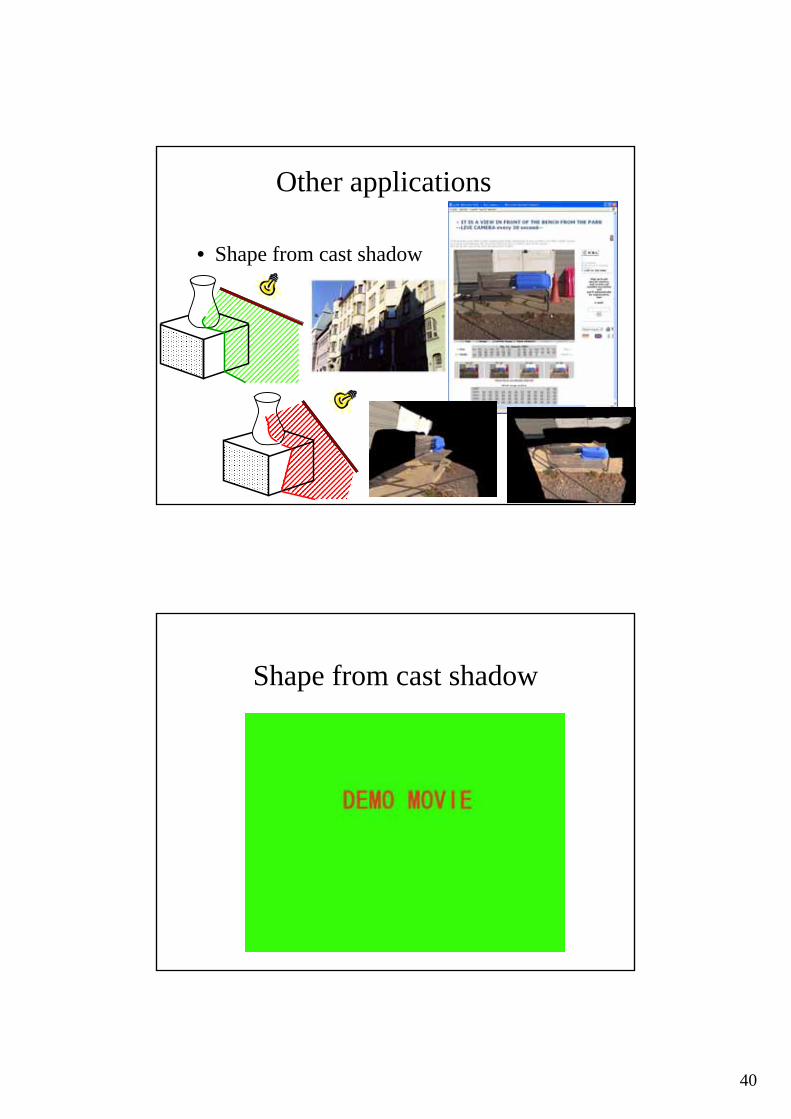
Other applications
• Shape from cast shadow
Shape from cast shadow

41
42
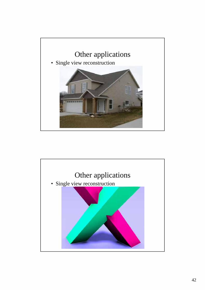
Other applications• Single view reconstruction
Other applications• Single view reconstruction
43
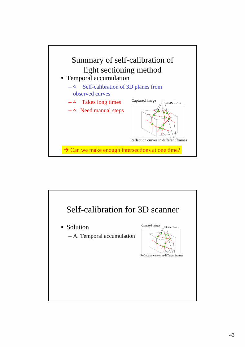
Summary of self-calibration of light sectioning method
• Temporal accumulation–○ Self-calibration of 3D planes from
observed curves–△ Takes long times–△ Need manual steps
Intersections
Reflection curves in different frames
Captured image
Can we make enough intersections at one time?
Self-calibration for 3D scanner
• Solution– A. Temporal accumulation
Intersections
Reflection curves in different frames
Captured image
44
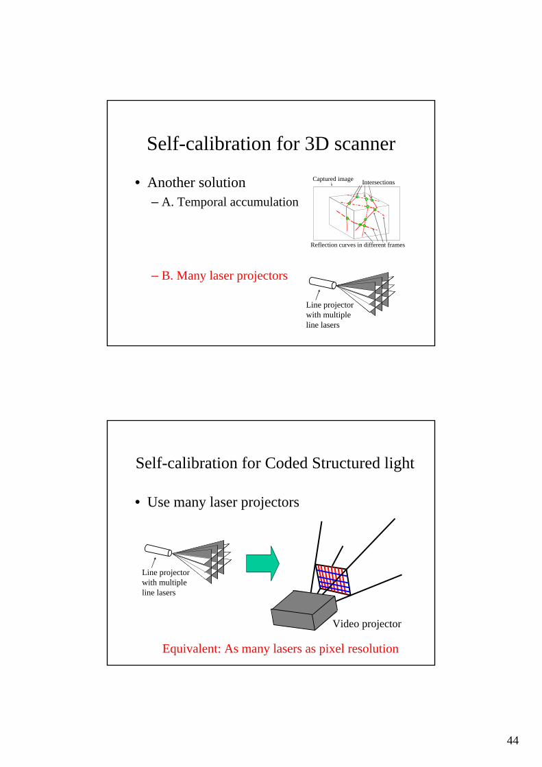
Self-calibration for 3D scanner
• Another solution– A. Temporal accumulation
– B. Many laser projectors
Line projectorwith multiple line lasers
Intersections
Reflection curves in different frames
Captured image
Self-calibration for Coded Structured light
• Use many laser projectors
Line projectorwith multiple line lasers
Equivalent: As many lasers as pixel resolution
Video projector
45
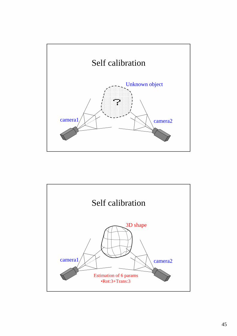
Self calibration
Unknown object
camera2camera1
?
Self calibration
camera2camera1
3D shape
Estimation of 6 params•Rot:3+Trans:3

46
Self calibration of projector camera system
Replace camera to projectorUnknown object
camera2camera1
?
Projector
Estimation of 6 params•Rot:3+Trans:3
Self calibration of pro-cams
Projecting image Camera image
correspondence

47
Actual implementation• Gray code method[’86 Inokuchi]
Structured light example• Projecting patterns two directions
• Acquired coded images
vertical horizontal
48
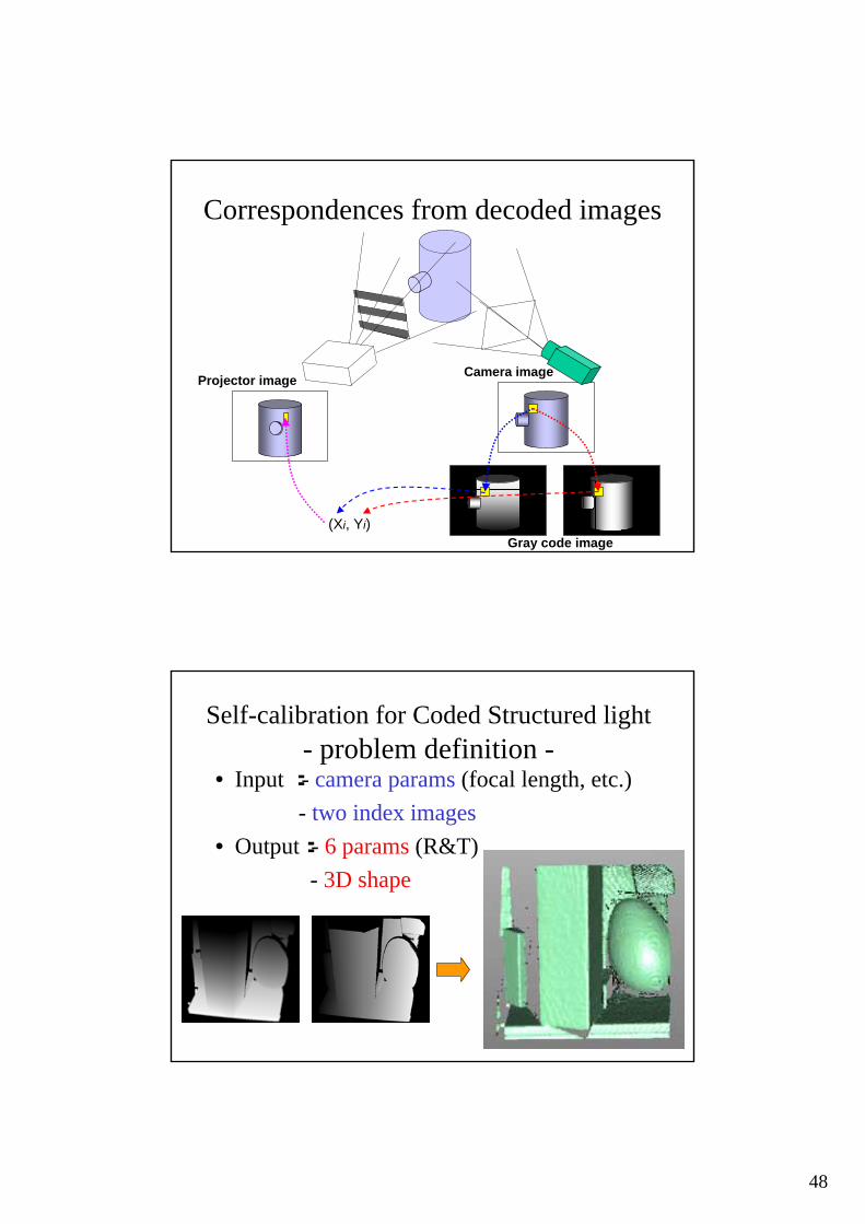
Correspondences from decoded images
(Xi, Yi)
Projector image Camera image
Gray code image
Self-calibration for Coded Structured light- problem definition -
• Input :- camera params (focal length, etc.) - two index images• Output:- 6 params (R&T)
- 3D shape
49
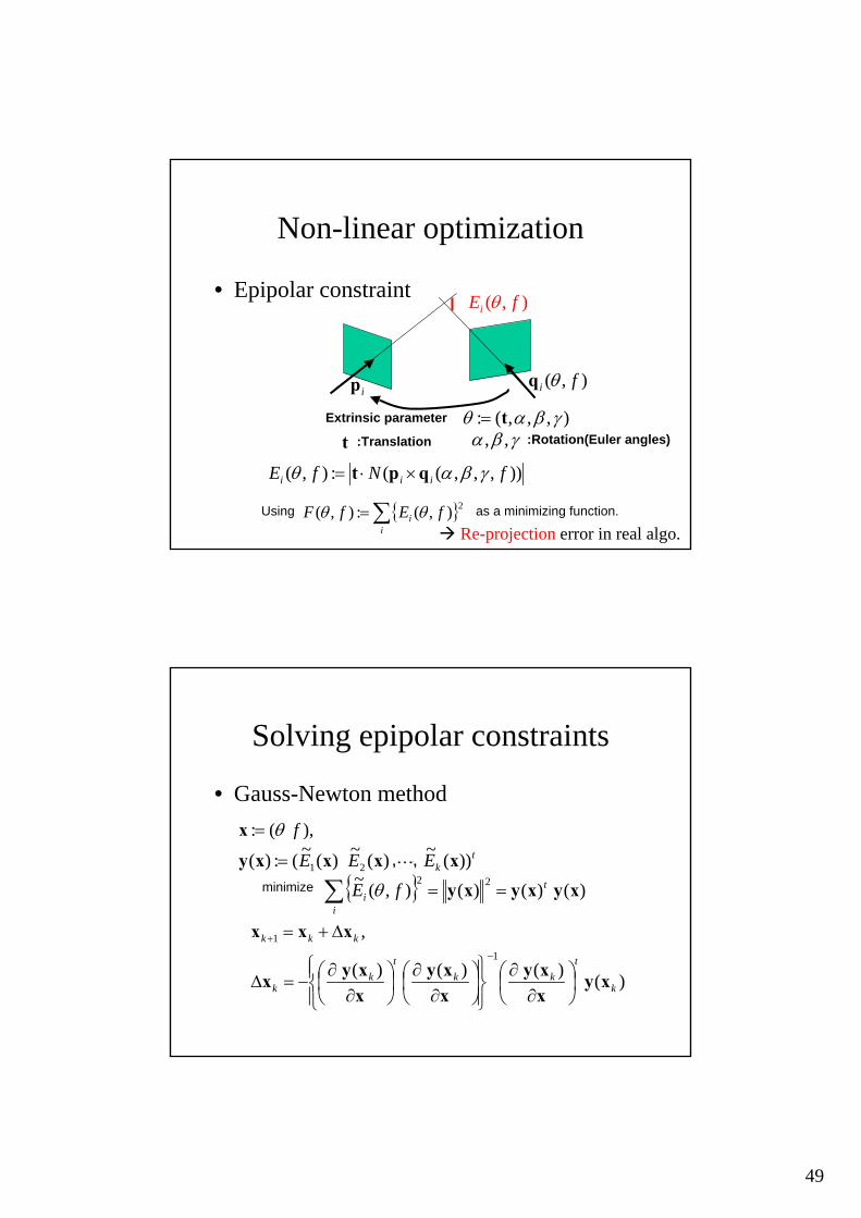
Non-linear optimization
• Epipolar constraint
)),,,((:),( fNfE iii γβαθ qpt ×⋅=
ip ),( fi θq
),,,(: γβαθ t=
Using as a minimizing function.{ }∑=i
i fEfF 2),(:),( θθ
Extrinsic parameter
t γβα ,,:Translation :Rotation(Euler angles)
),( fEi θ
Re-projection error in real algo.
Solving epipolar constraints
• Gauss-Newton method
tkEEE
f
))(~)(~)(~(:)(
),(:
21 xxxxy
x
L=
= θ
{ } )()()(),(~ 22xyxyxy t
ii fE ==∑ θminimize
)()()()(
,1
1
k
tkk
tk
k
kkk
xyxxy
xxy
xxyx
xxx
⎟⎠⎞
⎜⎝⎛
∂∂
⎪⎭
⎪⎬⎫
⎪⎩
⎪⎨⎧
⎟⎠⎞
⎜⎝⎛
∂∂
⎟⎠⎞
⎜⎝⎛
∂∂
−=∆
∆+=−
+
,・・・,
50
Demo
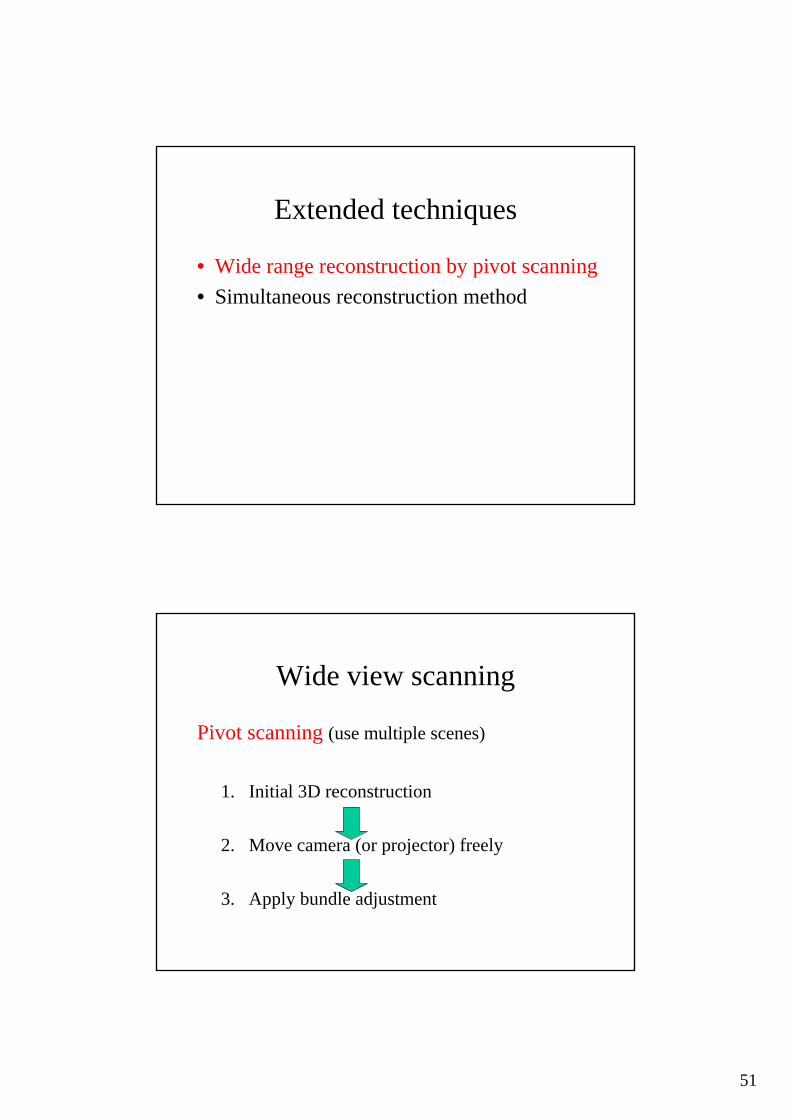
Extended techniques
• Wide range reconstruction by pivot scanning• Simultaneous reconstruction method
51
Extended techniques
• Wide range reconstruction by pivot scanning• Simultaneous reconstruction method
Wide view scanning
Pivot scanning (use multiple scenes)
1. Initial 3D reconstruction
2. Move camera (or projector) freely
3. Apply bundle adjustment
52
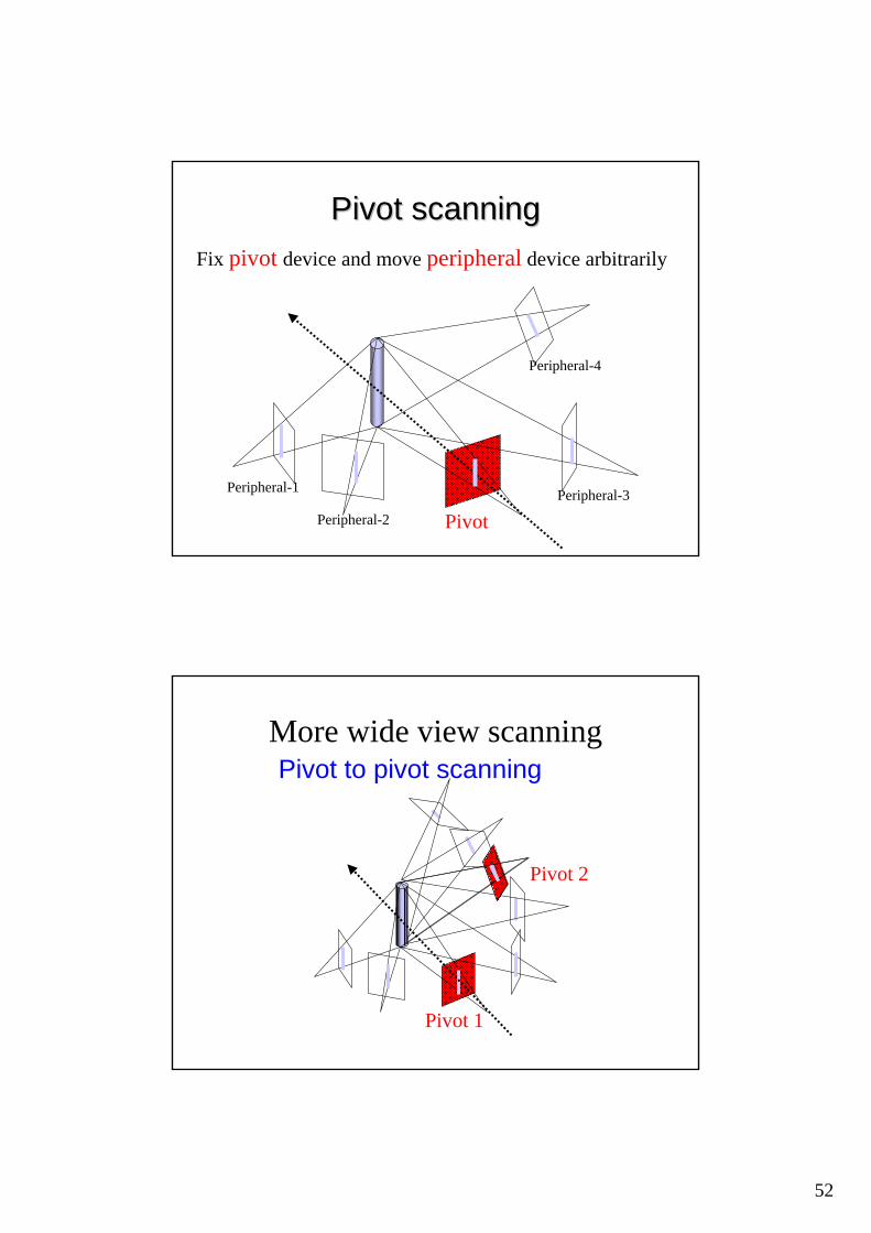
PivotPeripheral-2
Peripheral-1 Peripheral-3
Peripheral-4
Pivot scanningPivot scanningFix pivot device and move peripheral device arbitrarily
Pivot 1
More wide view scanning
New Pivot
Pivot 2
Pivot 1
Pivot to pivot scanning
53
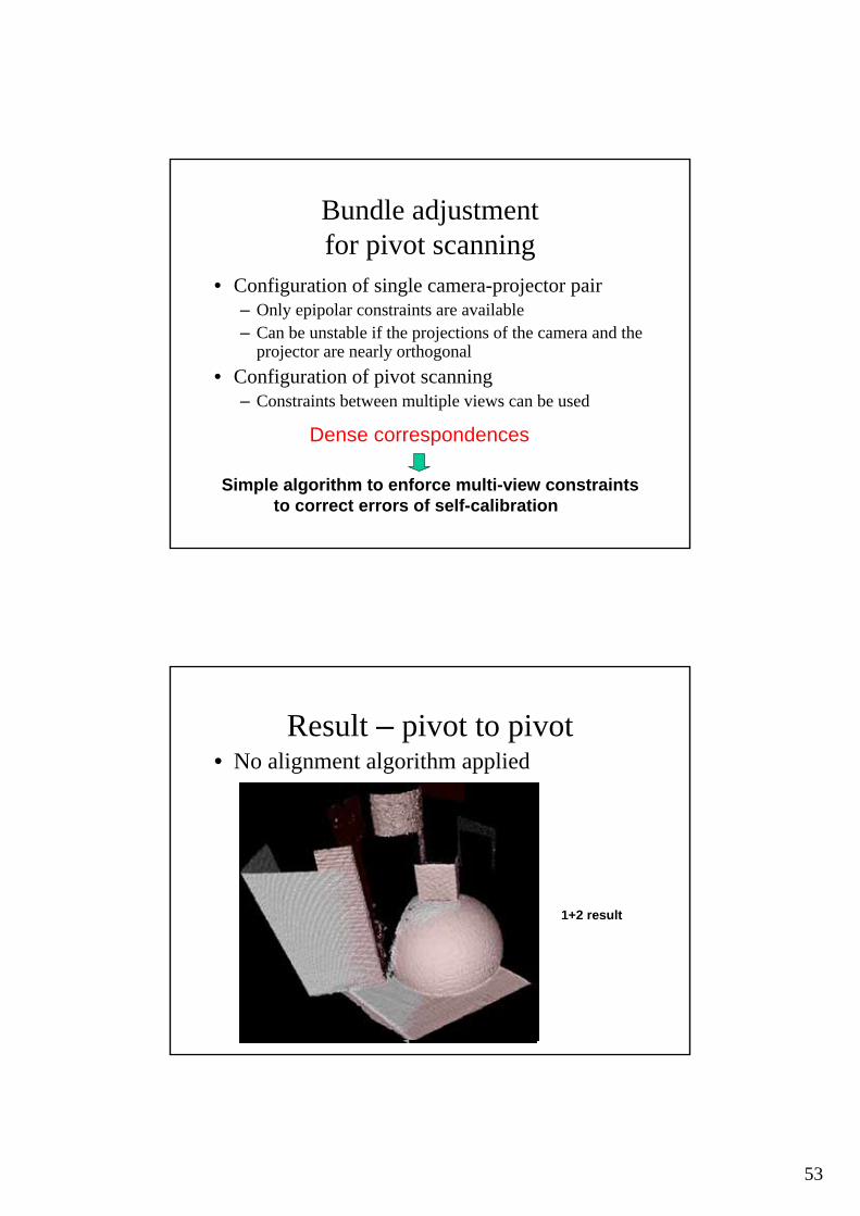
Bundle adjustment for pivot scanning
• Configuration of single camera-projector pair– Only epipolar constraints are available– Can be unstable if the projections of the camera and the
projector are nearly orthogonal• Configuration of pivot scanning
– Constraints between multiple views can be used
Dense correspondences
Simple algorithm to enforce multi-view constraintsto correct errors of self-calibration
Result – pivot to pivot• No alignment algorithm applied
1st pivot2nd pivot1+2 result
54
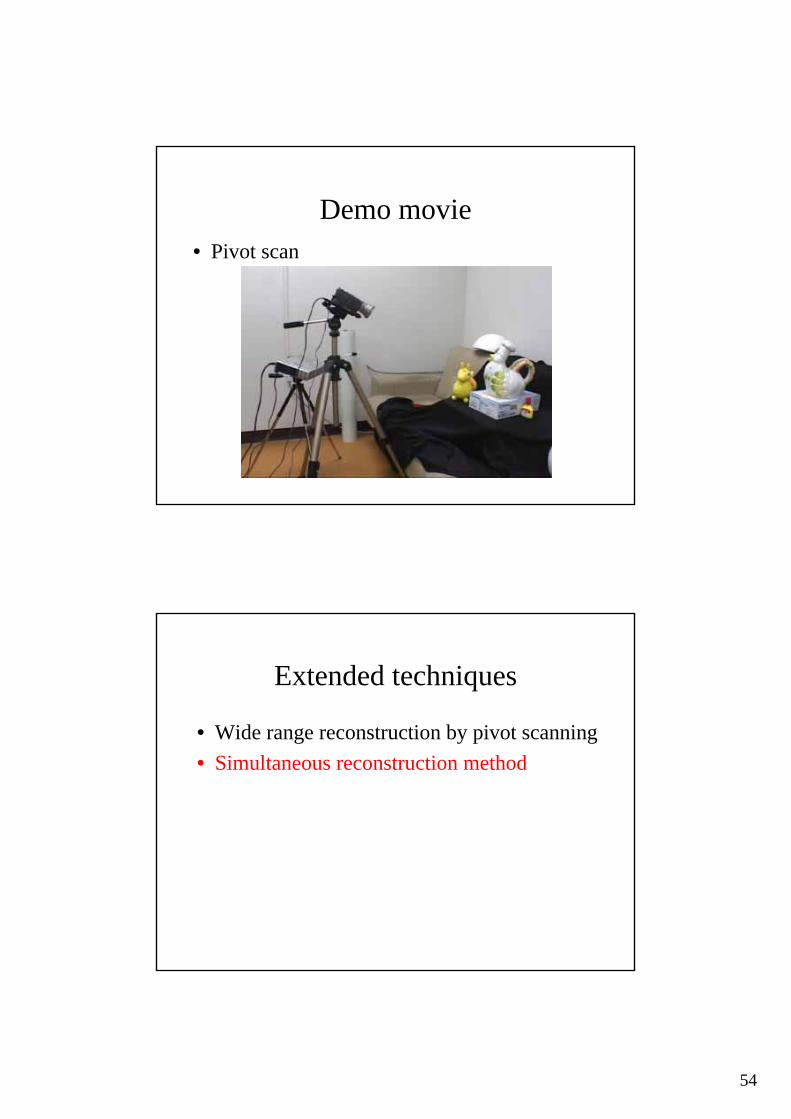
Demo movie• Pivot scan
Extended techniques
• Wide range reconstruction by pivot scanning• Simultaneous reconstruction method
55
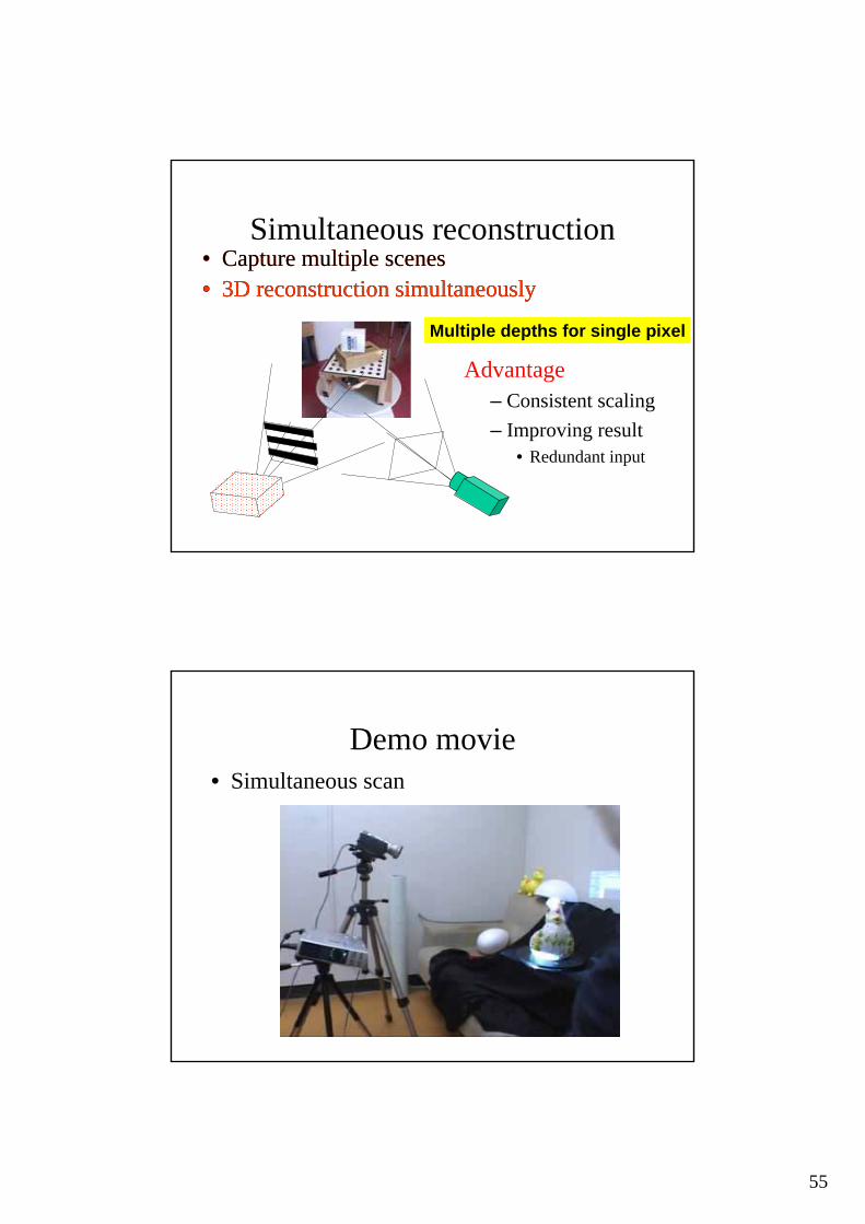
Simultaneous reconstruction• Capture multiple scenes• 3D reconstruction simultaneously
Advantage– Consistent scaling– Improving result
• Redundant input
Multiple depths for single pixel
• Capture multiple scenes• 3D reconstruction simultaneously
Demo movie• Simultaneous scan
56
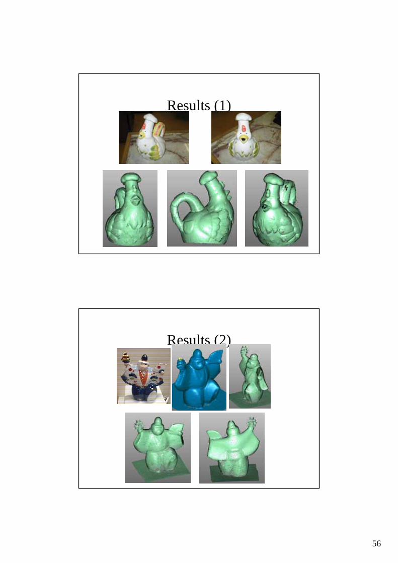
Results (1)
Results (2)

57
Final results
•Fast mesh integration [Furukawa and Kawasaki 3DIM ’05]•seamless texture [Inose, kawasaki et.al. ’06 ’07]
With
Conclusion
• Introduction of structured light system• Explain calibration problem• Self calibration techniques for
– Light sectioning method– Projector camera system

58
Discussion
• Calibration of light sectioning method and procam system is different
• Once correspondences are obtained, self-calibration is possible– Correspondence is an essential problem
In the next tutorial (part II)…
• Explain about correspondence problem• Scanning techniques for moving object

59
Thanks
• Any question?