Embed Size (px)
Citation preview

Structures and Processes for Managing
Model-Metamodel Co-evolution
Louis Mathew Rose
Department of Computer ScienceUniversity of York
This thesis is submitted in partial fulfilmentof the requirements for the degree of
Doctor of Philosophy.
July 2011
i

iii
Abstract
Software changes over time. During the lifetime of a software system, un-intended behaviour must be corrected and new requirements satisfied. Becausesoftware changes are costly, tools for automatically managing change are com-monplace. Contemporary software development environments can automaticallyperform change management tasks such as impact analysis, refactoring and back-ground compilation.
Increasingly, models and modelling languages are first-class citizens in soft-ware development. Model-Driven Engineering (MDE), a state-of-the-art approachto software engineering, prescribes the use of models throughout the software en-gineering process. In MDE, modelling tools and task-specific language are used togenerate an ultimate artefact, such as simulation models or working code.
Contemporary MDE environments provide little support for managing a typeof evolution termed model-metamodel co-evolution, in which changes to a mod-elling language are propagated to models. This thesis demonstrates that model-metamodel co-evolution occurs often in MDE projects, and that dedicated struc-tures and processes for its management can increase developer productivity. Struc-tures and processes for managing model-metamodel co-evolution are proposed, de-veloped, and then evaluated by comparison to existing structures and processeswith quantitative and qualitative techniques.


For my Nanna Spence


Contents
Contents vii
List of Figures ix
List of Tables xii
Listings xiii
Author Declaration xix
1 Introduction 11.1 An Overview of Model-Driven Engineering . . . . . . . . . . . . . . . . . 21.2 An Overview of Software Evolution . . . . . . . . . . . . . . . . . . . . . 21.3 Motivation: Software Evolution in MDE . . . . . . . . . . . . . . . . . . 31.4 Research Hypothesis and Method . . . . . . . . . . . . . . . . . . . . . . 41.5 Results of the Thesis Research . . . . . . . . . . . . . . . . . . . . . . . 71.6 Thesis Structure . . . . . . . . . . . . . . . . . . . . . . . . . . . . . . . 7
2 Background: Model-Driven Engineering 92.1 MDE Terminology and Principles . . . . . . . . . . . . . . . . . . . . . . 92.2 MDE Guidelines and Methods . . . . . . . . . . . . . . . . . . . . . . . 202.3 Tools for MDE . . . . . . . . . . . . . . . . . . . . . . . . . . . . . . . . 252.4 Research Relating to MDE . . . . . . . . . . . . . . . . . . . . . . . . . 312.5 Benefits of and Current Challenges to MDE . . . . . . . . . . . . . . . . 342.6 Chapter Summary . . . . . . . . . . . . . . . . . . . . . . . . . . . . . . 36
3 Review of Software Evolution 373.1 Software Evolution Theory . . . . . . . . . . . . . . . . . . . . . . . . . 373.2 Software Evolution in Practice . . . . . . . . . . . . . . . . . . . . . . . 423.3 Challenges to Managing Software Evolution in MDE . . . . . . . . . . . 593.4 Chapter Summary . . . . . . . . . . . . . . . . . . . . . . . . . . . . . . 60
4 MDE and Evolution: Problem Analysis 634.1 Examples of Evolution from MDE Projects . . . . . . . . . . . . . . . . 64
vii

viii CONTENTS
4.2 An Analysis of Existing Co-Evolution Techniques . . . . . . . . . . . . . 714.3 Requirements for Identifying and Managing Co-Evolution . . . . . . . . 834.4 Chapter Summary . . . . . . . . . . . . . . . . . . . . . . . . . . . . . . 85
5 Design and Implementation 875.1 A Metamodel-Independent Syntax . . . . . . . . . . . . . . . . . . . . . 895.2 Epsilon HUTN: A Textual Modelling Notation . . . . . . . . . . . . . . 1005.3 An Analysis of Languages used for Model Migration . . . . . . . . . . . 1175.4 Epsilon Flock: A Model Migration Language . . . . . . . . . . . . . . . 1245.5 Chapter Summary . . . . . . . . . . . . . . . . . . . . . . . . . . . . . . 146
6 Evaluation 1496.1 Evaluating User-Driven Co-Evolution . . . . . . . . . . . . . . . . . . . . 1506.2 Evaluating Conservative Copy . . . . . . . . . . . . . . . . . . . . . . . . 1646.3 Evaluating Epsilon Flock and other Co-evolution Tools . . . . . . . . . . 1836.4 Evaluating Co-Evolution Tools with an Example from UML . . . . . . . 1986.5 Limitations of the Proposed Structures and Processes . . . . . . . . . . 2126.6 Chapter Summary . . . . . . . . . . . . . . . . . . . . . . . . . . . . . . 213
7 Conclusions 2157.1 Contributions of the Thesis Research . . . . . . . . . . . . . . . . . . . . 2167.2 Future Work . . . . . . . . . . . . . . . . . . . . . . . . . . . . . . . . . 2197.3 Closing Remarks . . . . . . . . . . . . . . . . . . . . . . . . . . . . . . . 221
A Code Listings 223A.1 Migrating Petri Nets with Ecore2Ecore . . . . . . . . . . . . . . . . . . . 223A.2 Model Management Operations for Epsilon HUTN . . . . . . . . . . . . 228
B A Graphical Editor for Process-Oriented Programs 247B.1 Iteration 1: Processes and Channels . . . . . . . . . . . . . . . . . . . . 248B.2 Iteration 2: Interoperability with GMF . . . . . . . . . . . . . . . . . . . 249B.3 Iteration 3: Shared Channels . . . . . . . . . . . . . . . . . . . . . . . . 249B.4 Iteration 4: Connection Points . . . . . . . . . . . . . . . . . . . . . . . 253B.5 Iteration 5: Connection Point Types . . . . . . . . . . . . . . . . . . . . 257B.6 Iteration 6: Nested Processes and Channels . . . . . . . . . . . . . . . . 260B.7 Summary . . . . . . . . . . . . . . . . . . . . . . . . . . . . . . . . . . . 261
C Co-evolution Examples 263C.1 Newsgroups Examples . . . . . . . . . . . . . . . . . . . . . . . . . . . . 263C.2 UML Example . . . . . . . . . . . . . . . . . . . . . . . . . . . . . . . . 268C.3 GMF Examples . . . . . . . . . . . . . . . . . . . . . . . . . . . . . . . . 274
D TTC Results 319
Bibliography 325

List of Figures
1.1 Overview of the research method. . . . . . . . . . . . . . . . . . . . . . . . . 6
2.1 Jackson’s definition of a model . . . . . . . . . . . . . . . . . . . . . . . . . 102.2 A fragment of the UML metamodel defined in MOF . . . . . . . . . . . . . 132.3 A State Machine metamodel. . . . . . . . . . . . . . . . . . . . . . . . . . . 162.4 An Object-Oriented metamodel. . . . . . . . . . . . . . . . . . . . . . . . . 162.5 Interactions between a PIM and several PSMs. . . . . . . . . . . . . . . . . 212.6 The tiers of standards used as part of MDA. . . . . . . . . . . . . . . . . . 212.7 An EMF model editor for state machines. . . . . . . . . . . . . . . . . . . . 262.8 EMF’s tree-based metamodel editor. . . . . . . . . . . . . . . . . . . . . . . 272.9 EMF’s graphical metamodel editor. . . . . . . . . . . . . . . . . . . . . . . . 282.10 The Emfatic textual metamodel editor for EMF. . . . . . . . . . . . . . . . 292.11 GMF state machine model editor. . . . . . . . . . . . . . . . . . . . . . . . 292.12 The architecture of Epsilon . . . . . . . . . . . . . . . . . . . . . . . . . . . 30
3.1 Categories of traceability link . . . . . . . . . . . . . . . . . . . . . . . . . . 413.2 Attribute to association end refactoring in EMF Refactor . . . . . . . . . . 513.3 Approaches to incremental transformation . . . . . . . . . . . . . . . . . . . 523.4 Example impact analysis pattern . . . . . . . . . . . . . . . . . . . . . . . . 543.5 An exemplar co-evolution process . . . . . . . . . . . . . . . . . . . . . . . . 573.6 Visualising a transformation chain . . . . . . . . . . . . . . . . . . . . . . . 58
4.1 Analysis chapter overview. . . . . . . . . . . . . . . . . . . . . . . . . . . . . 634.2 Refactoring a reference to a value . . . . . . . . . . . . . . . . . . . . . . . . 704.3 Co-evolution activities . . . . . . . . . . . . . . . . . . . . . . . . . . . . . . 724.4 User-driven co-evolution with EMF . . . . . . . . . . . . . . . . . . . . . . . 744.5 COPE’s Make Reference Containment operation. . . . . . . . . . . . . . . . 784.6 Metamodel evolution in the Epsilon FPTC tool . . . . . . . . . . . . . . . . 804.7 Spectrum of developer-driven co-evolution approaches . . . . . . . . . . . . 83
5.1 Implementation chapter overview. . . . . . . . . . . . . . . . . . . . . . . . 875.2 The relationships between the proposed structures . . . . . . . . . . . . . . 885.3 Evolution of a families metamodel . . . . . . . . . . . . . . . . . . . . . . . 895.4 A family model . . . . . . . . . . . . . . . . . . . . . . . . . . . . . . . . . . 90
ix
x List of Figures
5.5 Objects resulting from the binding of a conformant model . . . . . . . . . . 915.6 A minimal generic metamodel for MOF . . . . . . . . . . . . . . . . . . . . 925.7 Loading models with the metamodel-independent syntax . . . . . . . . . . . 935.8 Pseudo code for binding XMI tags to Objects. . . . . . . . . . . . . . . . . 955.9 Metamodel-independent binding of the families metamodel . . . . . . . . . 955.10 Minimal MOF metamodel, based on [OMG 2008a]. . . . . . . . . . . . . . . 965.11 The constraints of the conformance checking service. . . . . . . . . . . . . . 965.12 Implemented version of the metamodel-independent syntax . . . . . . . . . 975.13 Evolution of a families metamodel . . . . . . . . . . . . . . . . . . . . . . . 1015.14 A family model . . . . . . . . . . . . . . . . . . . . . . . . . . . . . . . . . . 1015.15 A metamodel for abstract syntax trees, in Ecore . . . . . . . . . . . . . . . 1075.16 The architecture of Epsilon HUTN. . . . . . . . . . . . . . . . . . . . . . . . 1085.17 Final version of the metamodel-independent syntax, in Ecore . . . . . . . . 1095.18 User-driven co-evolution with dedicated structures . . . . . . . . . . . . . . 1155.19 Conformance problem reporting in Epsilon HUTN. . . . . . . . . . . . . . . 1165.20 Petri nets metamodel evolution . . . . . . . . . . . . . . . . . . . . . . . . . 1185.21 Mappings between the original and evolved Petri nets metamodels . . . . . 1205.22 The abstract syntax of Flock. . . . . . . . . . . . . . . . . . . . . . . . . . . 1255.23 Evolution of the Process-Oriented metamodel . . . . . . . . . . . . . . . . . 1295.24 Process-Oriented model prior to migration . . . . . . . . . . . . . . . . . . . 1305.25 UML metamodel evolution . . . . . . . . . . . . . . . . . . . . . . . . . . . 1345.26 Evolution of a unidirectional to a bidirectional reference. . . . . . . . . . . . 1375.27 Epsilon GUI for selecting a value at runtime . . . . . . . . . . . . . . . . . . 1405.28 A metamodel that uses inheritance . . . . . . . . . . . . . . . . . . . . . . . 144
6.1 Final version of the prototypical graphical model editor. . . . . . . . . . . . 1526.2 The graphical editor at the start of the iteration. . . . . . . . . . . . . . . . 1536.3 The graphical editor at the end of the iteration. . . . . . . . . . . . . . . . . 1546.4 Process-oriented metamodel evolution. . . . . . . . . . . . . . . . . . . . . . 1556.5 User-driven co-evolution with EMF . . . . . . . . . . . . . . . . . . . . . . . 1576.6 XMI prior to migration . . . . . . . . . . . . . . . . . . . . . . . . . . . . . 1586.7 XMI after migration . . . . . . . . . . . . . . . . . . . . . . . . . . . . . . . 1596.8 User-driven co-evolution with dedicated structures . . . . . . . . . . . . . . 1606.9 HUTN source prior to migration . . . . . . . . . . . . . . . . . . . . . . . . 1616.10 HUTN source part way through migration . . . . . . . . . . . . . . . . . . . 1626.11 Petri nets metamodel evolution . . . . . . . . . . . . . . . . . . . . . . . . . 1716.12 Simplified fragment of the GMF Graph metamodel. . . . . . . . . . . . . . 1776.13 Change Reference to Containment metamodel evolution . . . . . . . . . . . 1816.14 Exemplar metamodel evolution (Petri nets) . . . . . . . . . . . . . . . . . . 1856.15 GMF graph metamodel evolution . . . . . . . . . . . . . . . . . . . . . . . . 1866.16 Migration tool performance comparison. . . . . . . . . . . . . . . . . . . . . 1946.17 Activity model in UML 1.4. . . . . . . . . . . . . . . . . . . . . . . . . . . . 2006.18 UML 1.4 Activity Graphs . . . . . . . . . . . . . . . . . . . . . . . . . . . . 2016.19 UML 2.2 Activity Diagrams . . . . . . . . . . . . . . . . . . . . . . . . . . . 201

List of Figures xi
6.20 Migrating Actions for the Core Task . . . . . . . . . . . . . . . . . . . . . . 2036.21 Migrating Actions for Extension 1 . . . . . . . . . . . . . . . . . . . . . . . 203
B.1 The process-oriented metamodel after one iteration. . . . . . . . . . . . . . 248B.2 The process-oriented metamodel after two iterations. . . . . . . . . . . . . . 249B.3 A diagram after the second iteration. . . . . . . . . . . . . . . . . . . . . . . 250B.4 The process-oriented metamodel after three iterations. . . . . . . . . . . . . 250B.5 HUTN migration between second and third metamodel versions . . . . . . . 252B.6 The process-oriented metamodel after the fourth iteration. . . . . . . . . . . 253B.7 A diagram after the fourth iteration. . . . . . . . . . . . . . . . . . . . . . . 255B.8 HUTN migration between third and fourth metamodel versions . . . . . . . 256B.9 The process-oriented metamodel after five iterations. . . . . . . . . . . . . . 257B.10 HUTN migration between fourth and fifth metamodel versions . . . . . . . 259B.11 The process-oriented metamodel after six iterations. . . . . . . . . . . . . . 260B.12 A diagram after the final iteration. . . . . . . . . . . . . . . . . . . . . . . . 262
C.1 Newsgroups metamodel during the Extract Person iteration . . . . . . . . . 264C.2 Newsgroups metamodel during the Resolve Replies iteration . . . . . . . . . 266C.3 Activities in UML 1.4 and UML 2.2 . . . . . . . . . . . . . . . . . . . . . . 269C.4 The Graph metamodel in GMF 1.0 and GMF 2.0 . . . . . . . . . . . . . . . 276

List of Tables
4.1 Candidates for study of evolution in existing MDE projects . . . . . . . . . 66
5.1 Relating the thesis requirements and proposed structures . . . . . . . . . . 885.2 Compliance of Epsilon HUTN with OMG HUTN . . . . . . . . . . . . . . . 1145.3 Properties of model migration approaches . . . . . . . . . . . . . . . . . . . 146
6.1 Model operation frequency (analysis examples). . . . . . . . . . . . . . . . . 1746.2 Model operation frequency (evaluation examples). . . . . . . . . . . . . . . 1746.3 Summary of comparison criteria. . . . . . . . . . . . . . . . . . . . . . . . . 1886.4 Summary of tool selection advice . . . . . . . . . . . . . . . . . . . . . . . . 1966.5 TTC scores for Epsilon Flock (unweighted). . . . . . . . . . . . . . . . . . . 209
D.1 Correctness scores . . . . . . . . . . . . . . . . . . . . . . . . . . . . . . . . 320D.2 Conciseness scores . . . . . . . . . . . . . . . . . . . . . . . . . . . . . . . . 320D.3 Clarity scores . . . . . . . . . . . . . . . . . . . . . . . . . . . . . . . . . . . 321D.4 Appropriateness scores . . . . . . . . . . . . . . . . . . . . . . . . . . . . . . 321D.5 Tool maturity scores . . . . . . . . . . . . . . . . . . . . . . . . . . . . . . . 322D.6 Reproducibility scores . . . . . . . . . . . . . . . . . . . . . . . . . . . . . . 322D.7 Extensions scores . . . . . . . . . . . . . . . . . . . . . . . . . . . . . . . . . 323D.8 Total (equally weighted) scores . . . . . . . . . . . . . . . . . . . . . . . . . 323D.9 Total (weighted) scores . . . . . . . . . . . . . . . . . . . . . . . . . . . . . 324
xii

Listings
2.1 M2M transformation in ETL . . . . . . . . . . . . . . . . . . . . . . . . 162.2 M2T transformation in EGL . . . . . . . . . . . . . . . . . . . . . . . . 172.3 T2M transformation in EMFText . . . . . . . . . . . . . . . . . . . . . . 182.4 Model validation in EVL . . . . . . . . . . . . . . . . . . . . . . . . . . . 194.1 Migration strategy for the refactoring in Figure 4.2 . . . . . . . . . . . . 695.1 Parsing XMI attributes (in Java) . . . . . . . . . . . . . . . . . . . . . . 975.2 Consistency constraint for instantiating a metamodel type . . . . . . . . 985.3 XMI for the family model in Figure 5.14 . . . . . . . . . . . . . . . . . . 1005.4 A metamodel-specific syntax for families in EBNF . . . . . . . . . . . . 1025.5 Specifying attributes with HUTN . . . . . . . . . . . . . . . . . . . . . . 1045.6 Specifying a containment reference with HUTN . . . . . . . . . . . . . . 1045.7 Specifying a simple reference with HUTN . . . . . . . . . . . . . . . . . 1055.8 Keywords and adjectives in HUTN . . . . . . . . . . . . . . . . . . . . . 1055.9 A reference block in HUTN . . . . . . . . . . . . . . . . . . . . . . . . . 1055.10 An infix reference in HUTN . . . . . . . . . . . . . . . . . . . . . . . . . 1065.11 An extract of the Epsilon HUTN grammar definition in EBNF . . . . . 1095.12 Transforming Nodes to PackageObjects with ETL. . . . . . . . . . . . . 1105.13 Consistency constraint for checking the uniqueness of identifiers . . . . . 1105.14 Higher-order transformation with EGL . . . . . . . . . . . . . . . . . . . 1115.15 The M2M transformation generated for the Families metamodel . . . . . 1135.16 OMG HUTN for people with mothers and fathers. . . . . . . . . . . . . 1155.17 HUTN for people with parents. . . . . . . . . . . . . . . . . . . . . . . . 1165.18 Part of the Petri nets migration in ATL . . . . . . . . . . . . . . . . . . 1195.19 Java method for deserialising a reference. . . . . . . . . . . . . . . . . . 1215.20 Petri nets model migration in COPE . . . . . . . . . . . . . . . . . . . . 1225.21 Concrete syntax of migrate and delete rules. . . . . . . . . . . . . . . . . 1265.22 Redefining equivalences for the Component model migration. . . . . . . 1305.23 Petri nets model migration in Flock . . . . . . . . . . . . . . . . . . . . 1315.24 UML model migration in Flock . . . . . . . . . . . . . . . . . . . . . . . 1335.25 Using a non-null check to guard a migration rule . . . . . . . . . . . . . 1355.26 Using primitive and collection values . . . . . . . . . . . . . . . . . . . . 1365.27 Using higher-order operations on collections . . . . . . . . . . . . . . . . 1365.28 Using metamodel types . . . . . . . . . . . . . . . . . . . . . . . . . . . 1375.29 Creating new model elements . . . . . . . . . . . . . . . . . . . . . . . . 138
xiii

xiv LISTINGS
5.30 Using a context-less custom operation . . . . . . . . . . . . . . . . . . . 1385.31 Using a custom operation in the context of a metamodel type . . . . . . 1395.32 Prompting for user input at runtime . . . . . . . . . . . . . . . . . . . . 1395.33 Changing and unsetting conservatively copied feature values . . . . . . . 1415.34 Casting feature values . . . . . . . . . . . . . . . . . . . . . . . . . . . . 1415.35 Using equivalent() to access migrated model elements . . . . . . . . 1425.36 Preventing the conservative copy of original model elements . . . . . . . 1425.37 Redefining equivalences for the Component model migration. . . . . . . 1435.38 A migration strategy for the evolution in Figure 5.28 . . . . . . . . . . . 1445.39 Using an operation to reduce the duplication in Listing 5.38 . . . . . . . 1456.1 Assignment operators in ATL . . . . . . . . . . . . . . . . . . . . . . . . 1696.2 The Petri nets model migration in ATL . . . . . . . . . . . . . . . . . . 1726.3 The Petri nets model migration in Groovy-for-COPE . . . . . . . . . . . 1736.4 Petri nets model migration in Flock . . . . . . . . . . . . . . . . . . . . 1736.5 An extract of the GMF Graph model migration in ATL . . . . . . . . . 1766.6 Simplified GMF Graph model migration in ATL . . . . . . . . . . . . . 1786.7 Simplified GMF Graph model migration in COPE . . . . . . . . . . . . 1796.8 Simplified GMF Graph model migration in Flock . . . . . . . . . . . . . 1806.9 Migration for Change Reference to Containment in ATL . . . . . . . . . 1816.10 Migration for Change Reference to Containment in Flock . . . . . . . . 1826.11 Migrating Actions . . . . . . . . . . . . . . . . . . . . . . . . . . . . . . 2056.12 Migrating FinalStates and Transitions . . . . . . . . . . . . . . . . . . . 2056.13 Migrating Pseudostates . . . . . . . . . . . . . . . . . . . . . . . . . . . 2056.14 Migrating ActivityGraphs . . . . . . . . . . . . . . . . . . . . . . . . . . 2066.15 Migrating Guards . . . . . . . . . . . . . . . . . . . . . . . . . . . . . . . 2066.16 Migrating Partitions . . . . . . . . . . . . . . . . . . . . . . . . . . . . . 2066.17 Migrating ObjectFlows . . . . . . . . . . . . . . . . . . . . . . . . . . . . 2076.18 Migrating ObjectFlowStates to a single ObjectFlow . . . . . . . . . . . 2076.19 Migrating Partitions without ObjectFlowStates . . . . . . . . . . . . . . 207A.3 Transforming AST models to intermediate models with ETL. . . . . . . 228A.4 Syntactic and Conformance Constraints in EVL. . . . . . . . . . . . . . 238A.5 Generating the intermediate to target model transformation . . . . . . . 243B.1 The annotated process-oriented metamodel after one iteration . . . . . . 248B.2 The annotated process-oriented metamodel after two iterations . . . . . 251B.3 The annotated process-oriented metamodel after four iterations . . . . . 253B.4 The annotated process-oriented metamodel after five iterations . . . . . 257B.5 The annotated process-oriented metamodel after six iterations . . . . . . 260C.1 The Newsgroup Extract Person migration in ATL . . . . . . . . . . . . 264C.2 The Newsgroup Extract Person migration in Groovy-for-COPE . . . . . 265C.3 The Newsgroup Extract Person migration in Flock . . . . . . . . . . . . 265C.4 The Newsgroup Resolve Replies migration in ATL . . . . . . . . . . . . 266C.5 The Newsgroup Resolve Replies migration in Groovy-for-COPE . . . . . 267C.6 The Newsgroup Resolve Replies migration in Flock . . . . . . . . . . . . 267C.7 UML activity diagram migration in ATL . . . . . . . . . . . . . . . . . . 268

LISTINGS xv
C.8 UML activity diagram migration in Groovy-for-COPE . . . . . . . . . . 272C.9 UML activity diagram migration in Flock . . . . . . . . . . . . . . . . . 273C.10 GMF Graph migration in ATL . . . . . . . . . . . . . . . . . . . . . . . 275C.11 GMF Graph migration in Groovy-for-COPE . . . . . . . . . . . . . . . . 287C.12 GMF Graph migration in Flock . . . . . . . . . . . . . . . . . . . . . . . 288C.13 GMF Generator migration in ATL . . . . . . . . . . . . . . . . . . . . . 289C.14 GMF Generator migration in Groovy-for-COPE . . . . . . . . . . . . . 313C.15 GMF Generator migration in Flock . . . . . . . . . . . . . . . . . . . . . 315


Acknowledgements
I thank my supervisors, Prof. Richard Paige and Dr. Fiona Polack, for theirinvaluable guidance, support and encouragement throughout my doctoralresearch. I am also very grateful to Dr. Dimitrios Kolovos for his adviceand for countless rewarding discussions. I thank Dr. Simon Poulding forreviewing a technical report of preliminary research results.
I would like to thank my colleagues in the department for their supportand friendship, particularly Dr. Heather Barber, Mark Read and TaraGilliam. For many interesting and entertaining discussions, I thank my col-leagues and friends in the Enterprise Systems group. I am also grateful toDr. Anne Etien, Dr. Antonio Cicchetti, Markus Herrmannsdorfer and Dr.Kelly Garces for the interesting debates and discussions that we have shared.
I would like to express gratitude to my parents and my brother Nathanfor their continued support and reassurance. Finally, I am eternally grate-ful to my partner, Kate Senior, for her patience and optimism, and for ourmany adventures together.
xvii


Author Declaration
Except where stated, all of the work contained in this thesis representsthe original contribution of the author. Section 6.3 reports collaborativeexperiments with model migration tools, and that section makes clear theroles of the author and other participants.
Parts of the work described in this thesis have been previously publishedby the author in:
• The Epsilon Generation Language, Louis M. Rose, Richard F.Paige, Dimitrios S. Kolovos and Fiona A.C. Polack in Proc. EuropeanConference on Model Driven Architecture – Foundations and Appli-cations (ECMDA-FA), volume 5095 of LNCS, pages 1-16. Springer,2008,[Rose et al. 2008b].• Constructing Models with the Human-Usable Textual Nota-
tion, Louis M. Rose, Richard F. Paige, Dimitrios S. Kolovos and FionaA.C. Polack in Proc. International Conference on Model Driven En-gineering Languages and Systems (MoDELS), volume 5301 of LNCS,pages 249-263. Springer, 2008, [Rose et al. 2008a].• An Analysis of Approaches to Model Migration, Louis M.
Rose, Richard F. Paige, Dimitrios S. Kolovos and Fiona A.C. Po-lack in Proc. Joint Model-Driven Software Evolution and Model Co-evolution and Consistency Management (MoDSE-MCCM) Workshop,co-located with MoDELS 2009, [Rose et al. 2009b].• Enhanced Automation for Managing Model and Metamodel
Inconsistency, Louis M. Rose, Dimitrios S. Kolovos, Richard F. Paigeand Fiona A.C. Polack in Proc. International Conference on Auto-mated Software Engineering (ASE), pages 545-549, ACM Press, 2009,[Rose et al. 2009a].• Concordance: An Efficient Framework for Managing Model
Integrity, Louis M. Rose, Dimitrios S. Kolovos, Nicholas Drivalos,James. R. Williams, Richard F. Paige, Fiona A.C. Polack, and KiranJ. Fernandes in Proc. European Conference on Modelling Founda-tions and Applications (ECMFA), volume 6138 of LNCS, pages 62-73.Springer, 2010, [Rose et al. 2010c].
xix

xx AUTHOR DECLARATION
• Model Migration with Epsilon Flock, Louis M. Rose, DimitriosS. Kolovos, Richard F. Paige, and Fiona A.C. Polack in Proc. Inter-national Conference on the Theory and Practice of Model Transforma-tions (ICMT), volume 6142 of LNCS, pages 184-198. Springer, 2010,[Rose et al. 2010f].
• Model Migration Case, Louis M. Rose, Dimitrios S. Kolovos, RichardF. Paige, and Fiona A.C. Polack in Proc. Transformation Tools Con-test (TTC), co-located with TOOLS Europe 2010, [Rose et al. 2010e].
• Migrating Activity Diagrams with Epsilon Flock,Louis M. Rose, Dimitrios S. Kolovos, Richard F. Paige, and Fiona A.C.Polack in Proc. Transformation Tools Contest (TTC), co-located withTOOLS Europe 2010,[Rose et al. 2010d].
• A Comparison of Model Migration Tools, Louis M. Rose, MarkusHerrmannsdoerfer, James R. Williams, Dimitrios S. Kolovos, KellyGarces, Richard F. Paige, and Fiona A.C. Polack in Proc. Interna-tional Conference on Model Driven Engineering Languages and Sys-tems (MoDELS), volume 6394 of LNCS, pages 6175. Springer, 2010,[Rose et al. 2010b].

Chapter 1
Introduction
Today’s software engineers build distributed and interoperating systems with sophisti-cated graphical interfaces rather than the insular, monolithic, and command-line drivenmainframe applications built by their predecessors. For example, the NatWest andRoyal Bank of Scotland banking systems were successfully unified in 2003, which in-volved processing 14 million customer records, 13 million account records and 22 milliondirect debits in a single weekend [RAE & BCS 2004, pg26]. Distributed and interoper-able systems are key requirements in the National Programme for IT1, which seeks tomodernise the United Kingdom’s National Health Service with computerised systemsfor managing the nation’s patient records. In the United States of America, the goals ofthe Department of Defense depend on increasingly complex systems, which encompass“thousands of platforms, sensors, decision nodes, weapons, and war-fighters connectedthrough heterogeneous wired and wireless networks” [Northrop 2006].
Some of the software demanded by users and developers today is so complicatedthat its construction is not possible, even using state-of-the-art software engineeringtechniques [Selic 2003]. For example, a large supermarket chain recently planned todevelop software for managing a new loyalty card scheme. However, implementing thesystem would have involved devising algorithms for efficiently searching 4 terabytes ofcustomer data, and it was deemed impossible to implement despite its obvious com-mercial advantages [RAE & BCS 2004, pg15]. Demand, however, does not appear toexceed capability in all areas of computer science.
Hardware development, for example, seems to advance more quickly than soft-ware development. Each year, faster personal computers with larger disk drives be-come available, while operating systems, office software and development environmentsseem to improve more gradually. Radical advances in software development ap-pear to occur only by raising the level of abstraction at which software is specified[Brooks Jr. 1987, Selic 2003, Kleppe et al. 2003]. Improvements to the training andeducation of software engineers have also been suggested as key for the construction ofincreasingly complex software systems [RAE & BCS 2004].
1http://www.connectingforhealth.nhs.uk/about/benefits/statement0607.pdf
1

2 CHAPTER 1. INTRODUCTION
1.1 An Overview of Model-Driven Engineering
Historically, raising the level of abstraction of software development has led to increasedproductivity [Brooks Jr. 1987, Barry 2006, Kelly & Tolvanen 2008]. For example, as-sembly language provides mnemonics for machine code, allowing developers to disregardextraneous detail (such as the binary representation of instructions). Object-orientationand functional programming permit further abstraction over assembly language, en-abling developers to express solutions in a manner that is more representative of theirproblem domain.
Model-Driven Engineering (MDE) is a contemporary approach to software engi-neering that seeks to abstract away from technological details (such as programminglanguages and off-the-shelf software components) and towards the problem domain ofthe system (for example: accounting, managing patient records, or searching the In-ternet) [Frankel 2002, Kleppe et al. 2003, Selic 2003]. To this end, MDE prescribes,throughout the software engineering process, the use of models to capture the relevantdetails of the problem domain. Software development is driven by manipulating (trans-forming, validating, merging, comparing, etc.) the models to automatically generatean ultimate artefact, such as working code or simulation models.
MDE reportedly provides many benefits over traditional approaches to software en-gineering. Conclusions drawn from two unpublished case studies suggest that MDE canlead to increased productivity by reducing the amount of time to develop a system, andby reducing the number of defects discovered throughout development [Watson 2008].MDE can be used to increase the productivity of software development and the main-tainability of software systems [Kleppe et al. 2003]. Separating platform-specific andplatform-independent details using MDE can facilitate greater portability of systems[Frankel 2002]. Section 2.5.1 discusses further benefits of MDE.
Notwithstanding its benefits, MDE introduces additional challenges for software de-velopment. Large models are commonplace in many software engineering projects, andcontemporary MDE environments have not be optimised to facilitate the manipulationof large models [Kolovos et al. 2008a]. More generally, MDE introduces new challengesfor managing change throughout the lifetime of a system [Mens & Demeyer 2007]. Thisthesis focuses on the latter challenge, which is part of a branch of computer sciencetermed software evolution.
1.2 An Overview of Software Evolution
Software changes over time. During the lifetime of a software system, unintendedbehaviour must be corrected and new requirements satisfied. Because modern softwaresystems are rarely isolated from other systems, changes are also made to facilitateinteroperability with new systems [Sjøberg 1993].
Software evolution is an area of computer science that focuses on the way in whicha software system changes over time in response to external pressures (such as changingrequirements, or the discovery of unintended behaviour). The terms software evolution

1.3. MOTIVATION: SOFTWARE EVOLUTION IN MDE 3
and software maintenance are used interchangeably in the software engineering litera-ture. In this thesis, evolution is preferred to maintenance, because the latter can implydeterioration caused by repeated use, and most software systems do not deteriorate inthis manner [Ramil & Lehman 2000]. Other than sharing some terminology, softwareevolution is not related to evolutionary algorithms, a branch of computer science thatencompasses genetic programming and genetic algorithms.
In the past, studies have suggested that software evolution can account for as muchas 90% of a development budget [Erlikh 2000, Moad 1990], and there is no reason tobelieve that the situation is different today. Although such figures have been describedas uncertain [Sommerville 2006, ch. 21], precise figures are not required to demonstratethat the effects of evolution can inhibit the productivity of software development.
For example, suppose that we are developing a software system using a combinationof hand-written code and off-the-shelf components. Part way through development,one of the components changes to support a new requirement. When using the newversion of the component, we must first determine whether our system exhibits anyunintended behaviour, identify the cause of the unintended behaviour, and change thesystem accordingly. The resources allocated to correcting any unintended behaviourare not being used to develop features for the users of our system.
Primarily, software evolution research seeks to reduce the cost of making changes toa system. Analysis of the effects of evolution facilitates decision making. For example,analysis of our system might indicate that using a new version of a component willintroduce three defects, but simplify the implementation of two features. Studyingthe way in which systems evolve leads to improvements in software development toolsand processes that reduce the effects of evolution. For example, contemporary softwaredevelopment environments recognise compilation as a common activity during softwareevolution, and often perform automatic and incremental compilation of source code inthe background. Future changes to a system might be anticipated by identifying theways in which the system has previously evolved. For example, understanding theways in which a system has been affected by using a new version of a componentmight highlight ways in which the system can be better protected against changes toits dependencies.
1.3 Motivation: Software Evolution in MDE
Proponents of MDE suggest that, compared to traditional approaches to software engi-neering, application of MDE leads to systems that better support evolutionary change[Kleppe et al. 2003]. Large-scale systems developed with traditional approaches tosoftware engineering have been described as examples of a modern-day Sisyphus2, whosedevelopers must constantly perform evolution to support conformance to changing stan-dards and interoperability with external systems [Frankel 2002]. Some proponentssuggest that MDE can be used to reduce the cost of software evolution [Frankel 2002],
2In Greek mythology, Sisyphus was condemned to an eternity of repeatedly rolling a boulder to thetop of a mountain, only to see it return to the mountain’s base.

4 CHAPTER 1. INTRODUCTION
while others report that MDE introduces additional challenges for managing softwareevolution [Mens & Demeyer 2007].
In particular, the evolution of models, modelling languages and other MDE devel-opment artefacts must be managed in MDE. Contemporary development environmentsprovide some assistance for performing software evolution activities (by, for example,providing transformations that automatically restructure code). However, there is littlesupport for software evolution activities that involve models and modelling languages.Chapters 3 and 4 review, analyse and motivate improvements to the way in whichsoftware evolution is identified and managed in contemporary MDE development envi-ronments. Chapters 5 and 6 explore the extent to which the productivity of identifyingand managing evolutionary change can be increased by extending contemporary MDEdevelopment environments with additional, dedicated structures and processes.
1.4 Research Hypothesis and Method
The research presented in this thesis explores the hypothesis below. The emboldenedterms are potentially ambiguous, and their definition follows the hypothesis.
In existing MDE projects, the evolution of MDE development artefactsis typically managed in an ad-hoc manner with little regard for re-use.Dedicated structures and processes for managing evolutionary changecan be designed by analysing evolution in existing MDE projects. Further-more, supporting those dedicated structures and processes in contemporaryMDE environments is beneficial in terms of increased productivity for soft-ware development activities pertaining to the management of evolutionarychange.
In this thesis, the terms below have the following definitions:
MDE development artefacts. Compared to traditional approaches to softwareengineering, MDE uses additional development artefacts as first-class citizens in thedevelopment process. The additional development artefacts peculiar to MDE includemodels and modelling languages, as well as model management operations (such asmodel transformations). Chapter 2 describes models, modelling languages and modelmanagement operations in more detail.
Managing evolutionary change. Contemporary computer systems are constructedby combining numerous interdependent artefacts. Evolutionary changes to one artefactcan affect other artefacts. For example, changing a database schema might cause datato become invalid with respect to the database integrity constraints, and changingsource code may require recompilation of object code to ensure the latter is an accuraterepresentation of the former. Managing evolutionary change typically comprises threerelated activities: identifying when a change has occurred, reporting the effects of a
1.4. RESEARCH HYPOTHESIS AND METHOD 5
change, and reconciling affected artefacts in response to a change. Chapter 3 reviewsexisting approaches to managing evolutionary change.
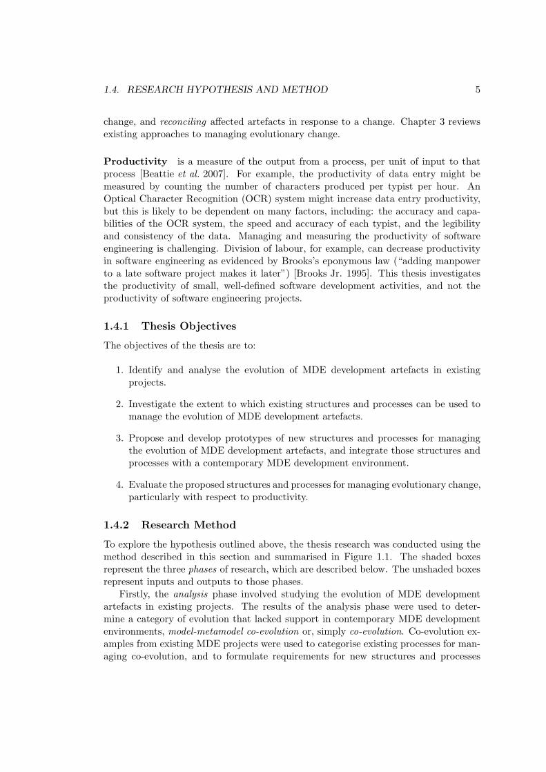
Productivity is a measure of the output from a process, per unit of input to thatprocess [Beattie et al. 2007]. For example, the productivity of data entry might bemeasured by counting the number of characters produced per typist per hour. AnOptical Character Recognition (OCR) system might increase data entry productivity,but this is likely to be dependent on many factors, including: the accuracy and capa-bilities of the OCR system, the speed and accuracy of each typist, and the legibilityand consistency of the data. Managing and measuring the productivity of softwareengineering is challenging. Division of labour, for example, can decrease productivityin software engineering as evidenced by Brooks’s eponymous law (“adding manpowerto a late software project makes it later”) [Brooks Jr. 1995]. This thesis investigatesthe productivity of small, well-defined software development activities, and not theproductivity of software engineering projects.
1.4.1 Thesis Objectives
The objectives of the thesis are to:
1. Identify and analyse the evolution of MDE development artefacts in existingprojects.
2. Investigate the extent to which existing structures and processes can be used tomanage the evolution of MDE development artefacts.
3. Propose and develop prototypes of new structures and processes for managingthe evolution of MDE development artefacts, and integrate those structures andprocesses with a contemporary MDE development environment.
4. Evaluate the proposed structures and processes for managing evolutionary change,particularly with respect to productivity.
1.4.2 Research Method
To explore the hypothesis outlined above, the thesis research was conducted using themethod described in this section and summarised in Figure 1.1. The shaded boxesrepresent the three phases of research, which are described below. The unshaded boxesrepresent inputs and outputs to those phases.
Firstly, the analysis phase involved studying the evolution of MDE developmentartefacts in existing projects. The results of the analysis phase were used to deter-mine a category of evolution that lacked support in contemporary MDE developmentenvironments, model-metamodel co-evolution or, simply co-evolution. Co-evolution ex-amples from existing MDE projects were used to categorise existing processes for man-aging co-evolution, and to formulate requirements for new structures and processes

6 CHAPTER 1. INTRODUCTION
Figure 1.1: Overview of the research method.
for managing co-evolution. The analysis phase also led to the identification of user-driven co-evolution, a process for managing co-evolution that has not previously beenrecognised in the co-evolution literature.
The implementation phase involved proposing, designing and implementing proto-types of novel structures for managing co-evolution, and integrating the prototypicalstructures with a contemporary MDE environment. The co-evolution examples identi-fied in the analysis phase were used for testing the implementation of the structures.
The evaluation phase involved assessing the novel structures for managing co-evolution by comparison to existing structures, and demonstrating the novel process.Evaluation was performed using further examples of co-evolution. To mitigate a pos-sible threat to the validity of the research, the examples used in the evaluation phasewere different from those used in the analysis phase. The strengths and weaknesses ofthe novel and existing structures and processes were synthesised from the comparisons,particularly with respect to the productivity of the development activities that are usedto manage co-evolution.

1.5. RESULTS OF THE THESIS RESEARCH 7
A similar method was successfully used to explore the extent to which component-based applications can be automatically evolved [Dig 2007]. Initially, analysis wasconducted to identify and categorise evolution in five existing component-based appli-cations, with the hypothesis that many of the changes could be classified as behaviour-preserving [Dig & Johnson 2006b]. Examples from the survey facilitated implementa-tion of a novel algorithm for the automatic detection of behaviour-preserving changes[Dig et al. 2006]. The algorithm was used to implement tools for migrating codein a distributed software development environment [Dig & Johnson 2006a], and foranalysing the history of component-based applications [Dig et al. 2007]. The latter fa-cilitated better understanding of program evolution, and refinement of the detectionalgorithm. Finally, evaluation of the tools and detection algorithm was performed byapplication to three further component-based applications [Dig 2007].
1.5 Results of the Thesis Research
This thesis proposes novel structures and processes for managing model-metamodelco-evolution. Prototypical reference implementations of the proposed structures havebeen constructed, including Epsilon HUTN (a textual modelling notation) and Ep-silon Flock (a model migration language). The reference implementations have ex-tended and reused Epsilon [Kolovos 2009], an extensible platform for specifying MDElanguages and tools, and are interoperable with the Eclipse Modelling Framework[Steinberg et al. 2008], arguably the most widely used MDE modelling framework.
Additionally, this thesis identifies a novel process for managing model-metamodelco-evolution and proposes a theoretical categorisation of existing process for managingmodel-metamodel co-evolution. The novel process, termed user-driven co-evolution, isdemonstrated by application to a MDE development process for a real-world project.
The research hypothesis has been validated by comparing the prototypes of theproposed structures and processes with existing structures and processes using exam-ples of evolution from real-world MDE projects. Evaluation has been performed usingseveral approaches, including a collaborative comparison of model migration tools car-ried out with three MDE experts, comparing quantitive measurements of the proposedand existing migration languages, and application of the proposed structures and pro-cesses to two examples of evolution, including an example from a widely used modellinglanguage, the Unified Modelling Language (UML) [OMG 2007a]. The evaluation alsoexplored areas in which the prototypical implementations of the proposed structuresand processes might be usefully improved to be fit for industrial use.
1.6 Thesis Structure
Chapter 2 gives an overview of MDE by defining terminology; describing associatedengineering principles, practices and tools; and reviewing related areas of computerscience. Section 2.5 synthesises some of the benefits of, and challenges for, contempo-rary MDE.

8 CHAPTER 1. INTRODUCTION
Chapter 3 reviews theoretical and practical software evolution research. Areas ofresearch that underpin software evolution are described, including refactoring, designpatterns, and traceability. The review then discusses work that approaches particularcategories of evolution problem, such as programming language, schema and grammarevolution. Section 3.2.4 surveys work that considers evolution in the context of MDE.Section 3.4 identifies three types of evolution that occur in MDE projects and highlightschallenges for their management.
Chapter 4 surveys existing MDE projects and categorises the evolution of MDEdevelopment artefacts in those projects. From this survey, the context for the thesisresearch is narrowed, and the remainder of the thesis focuses on one type of evolution oc-curring in MDE projects, termed model-metamodel co-evolution or simply co-evolution.Examples of co-evolution are used to identify the strengths and weaknesses of existingstructures and processes for managing co-evolution. From this, Section 4.2.2 identifiesa process for managing co-evolution which has not been recognised previously in theliterature, Section 4.2.3 derives a categorisation of existing processes for managing co-evolution, and Section 4.3 synthesises requirements for novel structures for managingco-evolution.
Chapter 5 describes novel structures for managing co-evolution, including a meta-model-independent syntax, which is used to identify, report and to facilitate the recon-ciliation of problems caused by metamodel evolution. The textual modelling notationdescribed in Section 5.2 and the model migration language described in Section 5.4are used for reconciliation of models in response to metamodel evolution. The latterprovides a means for performing reconciliation in a repeatable manner.
Chapter 6 assesses the structures and processes proposed in this thesis by compar-ison to existing structures and processes. To explore the research hypothesis, severaldifferent types of comparison were performed, including an experiment in which quan-titive measurements were derived, a collaborative comparison of model migration toolswith three MDE experts, and application to a large, independent example of evolutiontaken from a real-world MDE project.
Chapter 7 summarises the achievements of the research, and discusses results inthe context of the research hypothesis. Limitations of the thesis research and areas offuture work are also outlined.

Chapter 2
Background: Model-DrivenEngineering
This chapter presents the thesis background, introduces concepts relating to Model-Driven Engineering (MDE), and surveys the MDE literature. Software evolution re-search is reviewed in Chapter 3. MDE is a principled approach to software engineer-ing in which models are produced and consumed throughout the engineering process.Section 2.1 introduces the terminology and fundamental principles used in MDE. Sec-tion 2.2 reviews guidance and three methods for performing MDE. Section 2.3 describescontemporary MDE environments. Two areas of research relating to MDE, domain-specific languages and language-oriented programming, are discussed in Section 2.4.Finally, the benefits of and current challenges for MDE are described in Section 2.5.
2.1 MDE Terminology and Principles
Software engineers using MDE construct and manipulate artefacts familiar from tra-ditional approaches to software engineering (such as code and documentation) and,in addition, work with different types of artefact, such as models, metamodels andmodel transformations. Furthermore, MDE involves new development activities, suchas model management. This section describes the artefacts and activities involved inMDE.
2.1.1 Models
Models are fundamental to MDE. Kurtev identifies many definitions of the term model[Kurtev 2004], including the following: “any subject using a system A that is neitherdirectly nor indirectly interacting with a system B to obtain information about thesystem B, is using A as a model for B” [Apostel 1960]. “A model is a representationof a concept. The representation is purposeful and used to abstract from reality theirrelevant details,” [Starfield et al. 1990]. “A model is a simplification of a systemwritten in a well-defined language,” [Bezivin & Gerbe 2001].
9

10 CHAPTER 2. BACKGROUND: MODEL-DRIVEN ENGINEERING
While there are many definitions of the term model, a common notion is that amodel is a representation of the real-world [Kurtev 2004, pg12]. The part of the real-world represented by a model is termed the domain, the object system or, simply thesystem. Another common notion is that a model may have either a textual or graphicalrepresentation [Kolovos et al. 2006].
Models that share some characteristics and can be used in place of their objectsystem have been described as analogous [Ackoff 1962]. An aeroplane toy that can flyis an analogous model of an aeroplane. In computer science, models can be used toconstruct a computer system. A model of an object system, say the lending service ofa library, might be used to decide the way in which data is stored on disk, or the wayin which a program is to be structured.
The models constructed in computer science can be regarded as analogous to twosystems: the object system (e.g. the library lending service in the real-world) and thecomputer system (e.g. the software and hardware used to implement a library lendingservice) [Jackson 1995]. A model can be used to think about both the real systemand the computer system. Figure 2.1 illustrates this notion further and suggests that amodel is both the description of the domain (object system) and the machine (computersystem) [Jackson 1995]. Computer scientists switch between designations when usinga model to think about the object system or to think about the software system.
Figure 2.1: Jackson’s definition of a model, taken from [Jackson 1995, pg.125].
Models can be unstructured (for example, sketches on a piece of paper) or structured(conform to some well-defined set of syntactic and semantic constraints). In softwareengineering, models are used widely to reason about object systems and computersystems. MDE recognises this, and seeks to drive the development of computer systemsfrom structured models.

2.1. MDE TERMINOLOGY AND PRINCIPLES 11
2.1.2 Modelling languages
In MDE, models are structured rather than unstructured [Kolovos 2009]. A modellinglanguage is the set of syntactic and semantic constraints used to define the structure ofa group of related models. In MDE, a modelling language is often specified as a modeland, hence the term metamodel is used in place of modelling language.
Conformance is a relationship between a metamodel and a model. A model con-forms to a metamodel when the metamodel specifies every concept used in the modeldefinition, and the model uses the metamodel concepts according to the rules specifiedby the metamodel [Bezivin 2005]. Conformance can be described by a set of constraintsbetween models and metamodels [Paige et al. 2007]. When all constraints are satisfied,a model conforms to a metamodel. For example, a conformance constraint might statethat every object in the model has a corresponding non-abstract class in the metamodel.
Metamodels facilitate model interchange and, therefore, interoperability betweenmodelling tools. For this reason, Evans recommends that software engineers “use awell-documented shared language that can express the necessary domain informationas a common medium of communication.” [Evans 2004, pg377]. To support this rec-ommendation, Evans discusses the way in which chemists have collaborated to define astandardised language for describing chemical structures, Chemical Markup Language(CML)1. The standardisation of CML has facilitated interoperability between tools forspecification, analysis and simulation.
A metamodel typically comprises three categories of constraint:
• The concrete syntax provides a notation for constructing models that con-form to the language. For example, a model may be represented as a collectionof boxes connected by lines. A standardised concrete syntax enables commu-nication. Concrete syntax may be optimised for consumption by machines (e.g.XML Metadata Interchange (XMI) [OMG 2007c]) or by humans (e.g. the UnifiedModelling Language (UML) [OMG 2007a]).
• The abstract syntax defines the concepts described by the language, such asclasses, packages, datatypes. The representation for these concepts is independentof the concrete syntax. For example, the implementation of a compiler might usean abstract syntax tree to encode the abstract syntax of a program (whereas theconcrete syntax for the same language may be textual or graphical).
• The semantics identifies the meaning of the modelling concepts with respectto the domain. For example, consider a modelling language defined to describegenealogy, and another to describe flora. Although both languages may definea tree construct, the semantics of a tree in one is likely to be different from thesemantics of a tree in the other. The semantics of a modelling language may bespecified rigorously, by defining a reference semantics in a formal language suchas Z [ISO/IEC 2002], or in a semi-formal manner by employing natural language.
1http://cml.sourceforge.net/

12 CHAPTER 2. BACKGROUND: MODEL-DRIVEN ENGINEERING
Concrete syntax, abstract syntax and semantics are used together to specify mod-elling languages [Alvarez et al. 2001]. There are many other ways of defining languages,but this approach is common in MDE: a metamodel is often used to define abstractsyntax, a grammar or text-to-model transformation to specify concrete syntax, andcode generators, annotated grammars or behavioural models to effect semantics.
2.1.3 MOF: A metamodelling language
Software engineers using MDE can re-use existing – and define new – metamodels.To facilitate interoperability between MDE tools, the Object Management Group(OMG)2 has standardised a language for specifying metamodels, the Meta-Object Facil-ity (MOF). Contemporary MDE tools are interoperable because MOF standardises theway in which models are represented with a further OMG standard, XML MetadataInterchange (XMI), a dialect of XML optimised for loading, storing and exchangingmodels.
Because MOF is a modelling language for describing modelling languages, it issometimes termed a metamodelling language. Part of the UML metamodel, defined inMOF, is shown in Figure 2.2. As discussed in Section 2.3, different kinds of concretesyntax can be used for MOF. Figure 2.2, for example, uses a concrete syntax similarto that of UML class diagrams. Specifically:
• Modelling constructs are drawn as boxes. The name of each modelling constructis emboldened. The name of abstract (uninstantiable) constructs are italicised.
• Attributes are contained within the box of their modelling construct. Each at-tribute has a name, a type (prefixed with a colon) and may define a default value(prefixed with an equals sign).
• Generalisation is represented using a line with an open arrow-head.
• References are specified using a line. An arrow illustrates the direction in whichthe reference may be traversed. Labels are used to name and define the multi-plicity of references.
• Containment references are specified by including a solid diamond on the con-taining end.
2http://www.omg.org

2.1
.M
DE
TE
RM
INO
LO
GY
AN
DP
RIN
CIP
LE
S13
Figure 2.2: A fragment of the UML metamodel defined in MOF, from [OMG 2007a].

14 CHAPTER 2. BACKGROUND: MODEL-DRIVEN ENGINEERING
Specifying modelling languages with a common metamodelling language, such asMOF, ensures consistency in the way in which modelling constructs are specified. MOFhas facilitated the construction of interoperable MDE tools that can be used witha range of modelling languages. Without a standardised metamodelling language,modelling tools were specific to one modelling language, such as UML. In contemporaryMDE environments, any number of modelling languages can be used together andmanipulated in a uniform manner.
Furthermore, when modelling languages are specified without using a commonmetamodelling language, identifying similarities between modelling languages is chal-lenging [Frankel 2002, pg97]. The sequel discusses the way in which models and meta-models are used to construct systems in MDE.
2.1.4 Model Management
In MDE, models are managed to produce software. The term model managementwas first used in 2004 to describe a collection of operators for manipulating models[Melnik 2004]. This thesis uses the term model management to refer to developmentactivities that manipulate models for the purpose of producing software. Model man-agement activities typical in MDE, such as model transformation and validation, arediscussed in this section. Section 2.2 discusses MDE guidelines and methods, and de-scribes the way in which model management activities are used together to producesoftware in MDE.
Model Transformation
Model transformation is a development activity in which software artefacts are derivedfrom others, according to some well-defined specification. There are three types ofmodel transformations: those specified between modelling languages (model-to-modeltransformation), those specified between modelling languages and textual artefacts(model-to-text-transformation) and those specified between textual artefacts and mod-elling languages (text-to-model transformation) [Kleppe et al. 2003]. Each type oftransformation has unique characteristics and tools, but share some common char-acteristics. The remainder of this section first introduces the commonalities and thendiscusses each type of transformation individually.
Common characteristics of model transformations The input to a transforma-tion is termed its source, and the output its target. In theory, a transformation can havemore than one source and more than one target, but not all transformation languagessupport multiple sources and targets. Consequently, much of the model transformationliterature considers single source and target transformations.
The similarities and differences of different model transformation languages havebeen categorised and compared using a feature model [Czarnecki & Helsen 2006]. Twofeatures peculiar to model transformation are relevant to the research presented in thisthesis, and are now discussed.

2.1. MDE TERMINOLOGY AND PRINCIPLES 15
Source-target relationship A new-target transformation creates afresh the tar-get model on each invocation, while an existing-target transformation updates an ex-isting model. Existing target transformations are used for partial (incremental) trans-formation and for preserving parts of the target model that are not derived from thesource model.
Domain language Transformations specified between source and target modelsthat conform to the same metamodel are termed endogenous or rephrasings, whiletransformations specified between a source and a target model that conform to differentmetamodels are termed exogenous or translations.
Endogenous, existing-target transformations are a special case of transformationand are termed refactorings. Refactorings have been studied in the context of softwareevolution and are discussed more thoroughly in Chapter 3.
Model-to-Model (M2M) Transformation M2M transformation is used to derivemodels from others. By automating the derivation of models from others, M2M trans-formation has the potential to reduce the cost of engineering large and complex systemsthat can be represented as a set of interdependent models [Sendall & Kozaczynski 2003].
M2M transformations are most often specified using a set of transformation rules[Czarnecki & Helsen 2006]. Each rule specifies the way in which a specific set of ele-ments in the source model is transformed to an equivalent set of elements in the targetmodel [Kolovos 2009, pg.44].
Many M2M transformation languages have been proposed, such as the Atlas Trans-formation Language (ATL) [Jouault & Kurtev 2005], VIsual Automated model TRAns-formations (VIATRA) [Varro & Balogh 2007] and the Epsilon Transformation Lan-guage (ETL) [Kolovos et al. 2008b]. There also exists a standard for M2M transfor-mation, Queries/Views/Transformations (QVT) [OMG 2005]. M2M transformationlanguages can be categorised according to their style, which is either declarative, im-perative or hybrid.
Declarative M2M transformation languages only provide constructs for mappingsource to target model elements and, as such, are not computationally complete. Con-sequently, the scheduling of rules can be implicit (determined by the execution engineof the transformation language). By contrast, imperative M2M transformation lan-guages are computationally complete, but often require rule scheduling to be explicit(specified by the user). Hybrid M2M transformation languages combine declarativeand imperative parts, are computationally complete, and provide a mixture of implicitand explicit rule scheduling.
Declarative M2M transformation languages cannot be used to solve some categoriesof transformation problem [Patrascoiu & Rodgers 2004]. Imperative M2M transforma-tion languages are argued to be difficult to write and maintain [Kolovos 2009, pg.45].Consequently, hybrid languages, such as ATL, are presently believed to be more suit-able for specifying model transformation than pure imperative or declarative languages[Kolovos et al. 2008b].

16 CHAPTER 2. BACKGROUND: MODEL-DRIVEN ENGINEERING
An example of an M2M transformation, written in the hybrid M2M transformationlanguage ETL, is shown in Listing 2.1. The source of the transformation is a statemachine model, conforming to the metamodel shown in Figure 2.3. The target of thetransformation is an object-oriented model, conforming to the metamodel shown inFigure 2.4. The transformation in Listing 2.1 comprises two rules.
Figure 2.3: A State Machine metamodel.
Figure 2.4: An Object-Oriented metamodel.
The first rule (lines 1-7) is named Machine2Package (line 1) and transformsMachines (line 2) into Packages (line 3). The body of the first rule (lines 5-6) specifiesthe way in which a Package, p, can be derived from a Machine, m. Specifically, thename of p is derived from the id of m (line 5), and the contents of p are derivedfrom the states of m (line 6).
The second rule (lines 9-16) transforms States (line 10) to Classes (line 11).Additionally, line 13 contains a guard to specify that the rule is only to be applied toStates whose isFinal property is false.
When executed, the transformation rules will be scheduled implicitly by the ex-ecution engine, and invoked once for each Machine and State in the source. Online 6 of Listing 2.1, the built-in equivalent() operation is used to produce a set ofClasses from a set of States by invoking the relevant transformation rule. This isan example of explicit rule scheduling, in which the user defines when a rule will becalled.
1 rule Machine2Package
2 transform m : StateMachine!Machine
3 to p : ObjectOriented!Package {
4
5 p.name := ’uk.ac.york.cs.’ + m.id;
6 p.contents := m.states.equivalent();
7 }
2.1. MDE TERMINOLOGY AND PRINCIPLES 17
8
9 rule State2Class
10 transform s : StateMachine!State
11 to c : ObjectOriented!Class
12
13 guard: not s.isFinal {
14
15 c.name := s.name + ’State’;
16 }
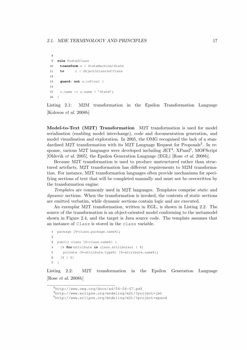
Listing 2.1: M2M transformation in the Epsilon Transformation Language
[Kolovos et al. 2008b]
Model-to-Text (M2T) Transformation M2T transformation is used for modelserialisation (enabling model interchange), code and documentation generation, andmodel visualisation and exploration. In 2005, the OMG recognised the lack of a stan-dardised M2T transformation with its M2T Language Request for Proposals3. In re-sponse, various M2T languages were developed including JET4, XPand5, MOFScript[Oldevik et al. 2005], the Epsilon Generation Language (EGL) [Rose et al. 2008b].
Because M2T transformation is used to produce unstructured rather than struc-tured artefacts, M2T transformation has different requirements to M2M transforma-tion. For instance, M2T transformation languages often provide mechanisms for speci-fying sections of text that will be completed manually and must not be overwritten bythe transformation engine.
Templates are commonly used in M2T languages. Templates comprise static anddynamic sections. When the transformation is invoked, the contents of static sectionsare emitted verbatim, while dynamic sections contain logic and are executed.
An exemplar M2T transformation, written in EGL, is shown in Listing 2.2. Thesource of the transformation is an object-oriented model conforming to the metamodelshown in Figure 2.4, and the target is Java source code. The template assumes thatan instance of Class is stored in the class variable.
1 package [%=class.package.name%];
2
3 public class [%=class.name%] {
4 [% for(attribute in class.attributes) { %]
5 private [%=attribute.type%] [%=attribute.name%];
6 [% } %]
7 }
Listing 2.2: M2T transformation in the Epsilon Generation Language
[Rose et al. 2008b]
3http://www.omg.org/docs/ad/04-04-07.pdf4http://www.eclipse.org/modeling/m2t/?project=jet5http://www.eclipse.org/modeling/m2t/?project=xpand

18 CHAPTER 2. BACKGROUND: MODEL-DRIVEN ENGINEERING
In EGL, dynamic sections are contained within [% and %]. Dynamic output sectionsare a specialisation of dynamic sections contained within [%= and %]. The resultof evaluating a dynamic output section is included in the generated text. Line 1 ofListing 2.2 contains two static sections (‘package’ and ‘;’) and a dynamic outputsection ([%=class.package.name%]), and will generate a package declaration whenexecuted. Similarly, line 3 will generate a class declaration. Lines 4 to 6 iterate overevery attribute of the class, outputting a field declaration for each attribute.
Text-to-Model (T2M) Transformation T2M transformation is most often imple-mented as a parser that generates a model rather than object code. Parser generatorssuch as ANTLR [Parr 2007] can be used to produce a structured artefact (such as anabstract syntax tree) from text. T2M tools typically reuse a parser generator, andpost-process the structured artefacts to produce a model that can be managed with aparticular modelling framework.
Xtext6 and EMFText [Heidenreich et al. 2009] are contemporary examples of T2Mtools that, given a grammar and a target metamodel, will automatically generate aparser that transforms text to a model.
An exemplar T2M transformation, written in EMFText, is shown in Listing 2.3.From the transformation shown in Listing 2.3, EMFText can be used to generatea parser that, when executed, will produce state machine models. For the input,lift[stationary up down stopping emergency], the parser will produce amodel containing one Machine with lift as its id, and five States with the names,stationary, up, down, stopping, and emergency.
Lines 1-2 of Listing 2.3 define the name of the parser and target metamodel. Line3 indicates that parser should first seek to construct a Machine from the source text.Lines 5-9 define rules for the lexer, including a rule for recognising IDENTIFIERs(represented as alphabetic characters).
Lines 11-14 of Listing 2.3 are key to the transformation. Line 11 specifies that aMachine is constructed whenever an IDENTIFIER is followed by a LBRACKET andeventually a RBRACKET. When constructing a Machine, the first time an IDENTIFIERis encountered, it is stored in the id attribute of the Machine. The states* state-ment on line 12 indicates that, before matching a RBRACKET, the parser is permitted totransform subsequent text to a State (according to the rule on line 13) and store theresulting State in the states reference of the Machine. The asterisks in states*indicates that any number of States can be constructed and stored in the statesreference.
1 SYNTAXDEF statemachine
2 FOR <statemachine>
3 START Machine
4
5 TOKENS {
6 DEFINE IDENTIFIER $(’a’..’z’|’A’..’Z’)*$;
6http://www.eclipse.org/Xtext/

2.1. MDE TERMINOLOGY AND PRINCIPLES 19
7 DEFINE LBRACKET $’[’$;
8 DEFINE RBRACKET $’]’$;
9 }
10
11 RULES {
12 Machine ::= id[IDENTIFIER] LBRACKET states* RBRACKET ;
13 State ::= name[IDENTIFIER] ;
14 }
Listing 2.3: T2M transformation in EMFText
Model Validation
Model validation provides a mechanism for managing the integrity of the softwaredeveloped using MDE. A model that omits information is said to be incomplete, whilerelated models that suggest differences in the underlying phenomena are said to becontradicting [Kolovos 2009]. Incompleteness and contradiction are two examples ofinconsistency [Elaasar & Briand 2004]. In MDE, inconsistency is detrimental, because,when artefacts are automatically derived from each other, the inconsistency of oneartefact might be propagated to others. Model validation is used to detect, report andreconcile inconsistency throughout a MDE process.
Inconsistency detection is inherently pattern-based and, hence, higher-order lan-guages are more suitable for model validation than so-called “third-generation” pro-gramming languages (such as Java) [Kolovos 2009]. The Object Constraint Language(OCL) [OMG 2006] is an OMG standard that can be used to specify consistency con-straints on UML and MOF models. OCL cannot express inter-model constraints, unlikethe Epsilon Validation Language (EVL) [Kolovos et al. 2009] and the xlinkit toolkit[Nentwich et al. 2003].
An exemplar model validation constraint, written in EVL, is shown in Listing 2.4.The constraint validates state machine models that conform to the metamodel shownin Figure 2.3. The constraint shown in Listing 2.4 is defined for States (line 1), andchecks that there exists some transition whose source or target is the current state (line4). When the check part (line 4) is not satisfied, the message part (line 6) is displayed.When executed, the EVL constraint will be invoked once for every State in the model.The keyword self is used to refer to the particular State on which the constraint iscurrently being invoked.
1 context State {
2 constraint NoStateIsAnIsland {
3 check:
4 Transition.all.exists(t | t.source == self or t.target == self)
5 message:
6 ’The state ’ + self.name + ’ has no transitions.’
7 }

20 CHAPTER 2. BACKGROUND: MODEL-DRIVEN ENGINEERING
8 }
Listing 2.4: Model validation in the Epsilon Validation Language
Further model management activities
In addition to model transformation and validation, further examples of model man-agement activities include model merging or weaving – in which two or more models arecombined (e.g. Reuseware [Henriksson et al. 2008]) – and model comparison in whicha trace of similar and different elements is produced from two or more models (e.g.EMF Compare [Brun & Pierantonio 2008]).
Further activities, such as model versioning and tracing, might be regarded as modelmanagement but, in the context of this thesis, are considered as evolutionary activitiesand as such are discussed in Chapter 3.
2.1.5 Summary
This section has introduced the terminology and principles necessary for discussingMDE in this thesis. Models provide abstraction, capturing necessary and disregard-ing irrelevant details. Metamodels provide a structured mechanism for describing thesyntactic and semantic rules to which a model must conform. Metamodels facilitateinteroperability between modelling tools. MOF, the OMG standard metamodelling lan-guage, enables the development of tools that can be used with a range of metamodels,such as model management tools. Throughout an MDE process, models are manipu-lated to produce other development artefacts using model management activities suchas model transformation and validation. Using the terms and principles described inthis section, the ways in which MDE is performed in practice are now discussed.
2.2 MDE Guidelines and Methods
For performing MDE, new engineering practices and processes have been proposed.Proponents of MDE have produced guidance and methods for MDE. This section dis-cusses the guidance for MDE set out in the Model-Driven Architecture [OMG 2008b]and three popular methods for MDE.
2.2.1 The Model-Driven Architecture
The Model-Driven Architecture (MDA) is a software engineering framework defined bythe OMG. The MDA provides guidelines for MDE. For instance, the MDA prescribesthe use of a Platform Independent Model (PIM) and one or more Platform SpecificModels (PSMs).
A PIM provides an abstract, implementation-agnostic view of a system. SuccessivePSMs provide increasingly more implementation detail. Inter-model mappings are usedto forward- and reverse-engineer these models, as depicted in Figure 2.5.

2.2. MDE GUIDELINES AND METHODS 21
Figure 2.5: Interactions between a PIM and several PSMs.
A key difference between the MDA and related approaches, such as round-tripengineering (in which models and code are co-evolved to develop a system), is that theMDA prescribes automated transformations between PIM and PSMs, whereas otherapproaches use some manual transformations.
With MDA, the OMG sought to communicate and encourage the adoption of MDEprinciples, and to provide standards for building interoperable MDE platforms. Ar-guably, some parts of MDA have been widely adopted. For example, the metamod-elling language provided by the Eclipse Modeling Framework (Section 2.3.1) is heavilybased on MOF (Section 2.1.3), one of the key standards prescribed by MDA. However,it is difficult to assess the extent to which the principles advocated by MDA have beenadopted. Empirical analysis is needed to determine the way in which MDE is performedin practice, and to drive changes to MDA and the modelling standards provided by theOMG.
Standards for the MDA
As part of the guidelines for MDE, the OMG prescribes a set of standards for the MDA.The standards are allocated to one of four tiers, and each tier represents a differentlevel of model abstraction (Figure 2.6). Members of one tier conform to a member ofthe tier above. A discussion of the four tiers, based on [Kleppe et al. 2003, Section 8.2],follows.
Figure 2.6: The tiers of standards used as part of MDA.
The base of the pyramid, tier M0, contains the domain (real-world). When mod-elling a business, this tier is used to describe items of the business itself, such as areal customer or an invoice. When modelling software, M0 instances describe the soft-
22 CHAPTER 2. BACKGROUND: MODEL-DRIVEN ENGINEERING
ware representation of such items. M1 contains models (Section 2.1.1) of the conceptsin M0, for example a customer may be represented as a class with attributes. TheM2 tier contains the modelling languages (metamodels, Section 2.1.2) used to describethe contents of the M1 tier. For example, if UML [OMG 2007a] models were used todescribe concepts as classes in the M1 tier, M2 would contain the UML metamodel.Finally, M3 contains a metamodelling language (metametamodel, Section 2.1.3) whichdescribes the modelling languages in the M2 tier. As discussed in Section 2.1.3, theM3 tier facilitates tool standardisation and interoperability. The MDA specifies theMeta-Object Facility (MOF) [OMG 2008a] as the only member of the M3 tier.
Interpretations of the MDA
The guidelines in the MDA have been interpreted by engineers in two distinct ways[McNeile 2003]. Both interpretations begin with a PIM, but the way in which exe-cutable code is produced differs:
• Translationist: The PIM is used to generate code directly using a sophisticatedcode generator. Any intermediate PSMs are internal to the code generator. Nogenerated artefacts are edited manually.
• Elaborationist: Any generated artefacts (such as PSMs, code and documenta-tion) can be augmented with further details of the application. To ensure thatall models and code are synchronised, tools must allow bi-directional transforma-tions.
Translationists must encode behaviour in PIMs [Mellor & Balcer 2002], whereaselaborationists can specify behaviour in PSMs or in code [Kleppe et al. 2003].
The difference between translationist and elaborationist approaches to MDE is re-lated to a difference in the way in which models are viewed in traditional approachesto software engineering. Modelling has been identified as a vital activity that shouldtake place throughout the development process [Evans 2004]. By contrast, it has alsobeen suggested that modelling should only be used for communicating and reason-ing about a design, and not “as a long-term replacement for real, working software”[Martin & Martin 2006, ch. 14].
Use of MDA
The guidelines set out in the MDA have been adopted – in varying degrees – by themethods for MDE described in the sequel. Tools for MDE (Section 2.3) tend not to en-force many of the MDA guidelines. For example, contemporary modelling frameworksallow – but do not force – developers to specify a single PIM and use model transforma-tion to create successive PSMs. The MDE standards prescribed by the MDA have beenwidely adopted. MOF, UML and XMI, for example, are used in many contemporarymodelling frameworks and modelling tools.

2.2. MDE GUIDELINES AND METHODS 23
2.2.2 Methods for MDE
Several methods for MDE are prevalent today. In this section, three of the mostestablished MDE methods are discussed: Architecture-Centric Model-Driven SoftwareDevelopment [Stahl et al. 2006], Domain-Specific Modelling [Kelly & Tolvanen 2008]and Software Factories [Greenfield et al. 2004] at Microsoft. All three methods havebeen defined by MDE practitioners, and have been used repeatedly to solve problemsin industry. The methods vary in the extent to which they follow the guidelines set outby the MDA.
Architecture-Centric Model-Driven Software Development
Architecture-centric model-driven software development (AC-MDSD) is a style of MDEthat focuses on generating the infrastructure of large applications [Stahl et al. 2006].For example, a typical J2EE application contains concepts (such as EJBs, descrip-tors, home and remote interfaces) that “admittedly contain domain-related informa-tion such as method signatures, but which also exhibit a high degree of redundancy”[Stahl et al. 2006]. Using code generation, AC-MDSD seeks to eliminate this kind ofredundancy. Domain-related information is specified in a single source (typically in amodel). The single source is used as input to code generators, which automaticallyproduce the implementation concepts.
AC-MDSD applies more of the MDA guidelines than the other methods discussedbelow. For instance, AC-MDSD supports the use of a general-purpose modelling lan-guage for specifying models. The way in which AC-MDSD may be used to enhancethe productivity, efficiency and understandability of software development has beendemonstrated for a small number of examples [Stahl et al. 2006]. In these examples,models are annotated using UML profiles to describe domain-specific concepts.
Domain-Specific Modelling
Domain-Specific Modelling (DSM) [Kelly & Tolvanen 2008] provides a collection ofprinciples, practices and advice for constructing systems using MDE. DSM is based onthe translationist interpretation of the MDA: domain models are transformed directlyto code. DSM has been motivated by comparison to the large productivity gainsmade when third-generation programming languages were used in place of assembler[Kelly & Tolvanen 2008]. Tolvanen7 notes that DSM focuses on increasing the pro-ductivity of software engineering by allowing developers to specify solutions by usingmodels that describe the application domain.
To perform DSM, expert developers define:
• A domain-specific modelling language: allowing domain experts to encodesolutions to their problems.
7Tutorial on Domain Specific Modelling for Full Code Generation at the Fourth European Confer-ence on Model Driven Architecture (ECMDA), June 2008, Berlin, Germany.

24 CHAPTER 2. BACKGROUND: MODEL-DRIVEN ENGINEERING
• A code generator: that translates the domain-specific models to executablecode in an existing programming language.
• Framework code: that encapsulates the common areas of all applications inthis domain.
As the development of these three artefacts requires significant effort from expertdevelopers, Tolvanen7 states that DSM should only be applied if more than threeproblems specific to the same domain are to be solved.
Tools for defining domain-specific modelling languages, editors and code generatorsenable DSM [Kelly & Tolvanen 2008]. Reducing the effort required to specify theseartefacts is key to the success of DSM. In this respect, DSM resembles a programmingparadigm termed language-oriented programming (LOP), which also requires tools tosimplify the specification of new languages. LOP is discussed further in Section 2.4.
Examples from industrial partners have been used to argue that DSM can improvedeveloper productivity [Kelly & Tolvanen 2008]. Unlike the MDA, DSM appears to beoptimised for increasing productivity, and less concerned with portability or maintain-ability. Therefore, DSM is less suitable for engineering applications that frequentlyinteroperate with – and are underpinned by – changing technologies.
Microsoft Software Factories
During the industrialisation of the automobile industry, problems with economies ofscale (mass production) and scope (product variation) were largely addressed and, as aconsequence, the efficiency of automobile production increased [Greenfield et al. 2004,pg159]. Software Factories [Greenfield et al. 2004], a software engineering method de-veloped at Microsoft, seeks to address problems with economies of scope in softwareengineering by borrowing concepts from product-line engineering. Software Factoriesfocuses on addressing economies of scope rather than economies of scale because, unlikemany other engineering disciplines, software development requires considerably moredevelopment effort than production effort [Greenfield et al. 2004].
Software Factories [Greenfield et al. 2004] prescribes a bottom-up approach to ab-straction and re-use. Development begins by producing prototypical applications. Thecommon elements of these applications are identified and abstracted into a product-line. When instantiating a product, models are used to choose values for the variationpoints in the product. To simplify the creation of these models, Software Factories pro-pose model creation wizards, because “moving from totally-open ended hand-coding tomore constrained forms of specification [such as wizard-based feature selection] are thekey to accelerating software development” [Greenfield et al. 2004, pg179]. By provid-ing explanations that assist in making decisions, the wizards used in Software Factoriesguide users towards best practices for customising a product.
Compared to DSM, Software Factories appears to provide more support for ad-dressing portability problems. The latter provides viewpoints into the product-line(essentially different ways of presenting and aggregating data from development arte-facts), which allow decoupling of concerns (e.g. between logical, conceptual and physical

2.3. TOOLS FOR MDE 25
layers). Viewpoints provide a mechanism for abstracting over different layers of plat-form independence, adhering more closely than DSM to the guidelines provided in theMDA. Unlike the guidelines provided in the MDA, Software Factories does not insistthat development artefacts be derived automatically where possible.
Finally, Software Factories prescribes the use of domain-specific languages (dis-cussed in Section 2.4.1) for describing models in conjunction with Software Factories,rather than general-purpose modelling languages, as the authors of Software Factoriesstate that the latter often have imprecise semantics [Greenfield et al. 2004].
2.2.3 Summary
This section has discussed the ways in which process and practices for MDE have beencaptured. Guidance for MDE has been set out in the MDA standard, which seeks touse MDE to produce adaptable software in a productive and maintainable manner.Three methods for performing MDE have been discussed.
The methods discussed share some characteristics. They all require a set of ex-emplar applications, which are examined by MDE experts. Analysis of the exemplarapplications identifies the way in which software development may be decomposed. Amodelling language for the problem domain is constructed, and instances are used togenerate future applications. Code common to all applications in the problem domainis encapsulated in a framework.
Each method has a different focus. AC-MDSD seeks to eliminate duplication ofinformation from the problem domain via automatic code generation, and targets en-terprise applications. Software Factories concentrates on providing different viewpointsinto the system, and facilitating collaborative specification of a system. DSM aims toimprove reusability between solutions to problems in the same problem domain, andhence improve developer productivity.
Perhaps unsurprisingly, the proponents of each method for MDE recommend asingle tool (such as MetaCase for DSM). Alternative tools are available from open-source modelling communities, including the Eclipse Modelling Project, which provides– among other MDE tools – arguably the most widely used MDE modelling framework.Two MDE tools are reviewed in the sequel.
2.3 Tools for MDE
Mature and powerful tools and languages for many common MDE activities are avail-able today. This section discusses two MDE tools that are well-suited for MDE researchand that are used in the remainder of the thesis.
Section 2.3.1 provides an overview of the Eclipse Modelling Framework (EMF)[Steinberg et al. 2008], which implements MOF and underpins many contemporaryMDE tools and languages, facilitating their interoperability. Section 2.3.2 discussesEpsilon [Kolovos 2009], an extensible platform for the specification of model manage-ment languages. The highly extensible nature of Epsilon (which is described below)

26 CHAPTER 2. BACKGROUND: MODEL-DRIVEN ENGINEERING
makes it an ideal host for the rapid prototyping of languages and exploring researchhypotheses.
The purpose of this section is to review EMF and Epsilon, and not to provide athorough review of all MDE tools. There are many other MDE tools and environmentsthat this section does not discuss, such as ATL and VIATRA for M2M transforma-tion (Section 2.1.4), oAW8 for model transformation and validation, and the AMMAplatform9 for large-scale modelling, model weaving and software modernisation.
2.3.1 Eclipse Modelling Framework
The Eclipse Foundation10 is an open-source community seeking to build an extensibleand integrated development platform. Within Eclipse, the Eclipse Modelling Frame-work (EMF) project [Steinberg et al. 2008] provides support for MDE. EMF providescode generation facilities, and a meta-modelling language, Ecore, that implements theMOF 2.0 standard [OMG 2008a]. EMF is arguably the most widely-used contemporaryMDE modelling framework.
EMF is used to generate metamodel-specific editors for loading, storing and con-structing models. EMF model editors comprise a navigation view for specifying theelements of the model, and a properties view for specifying the features of model ele-ments. Figure 2.7 shows an EMF model editor for a simple state machine language.The navigation (or tree) view is shown in the top pane, while the properties view isshown in the bottom pane.
Figure 2.7: An EMF model editor for state machines.
8http://www.eclipse.org/workinggroups/oaw/9http://wiki.eclipse.org/AMMA
10http://www.eclipse.org

2.3. TOOLS FOR MDE 27
Users of EMF can define their own metamodels in Ecore, the metamodelling lan-guage and MOF implementation of EMF. EMF provides two metamodel editors, tree-based and graphical. Figure 2.8 shows the metamodel of a simple state machine lan-guage in the tree-based metamodel editor. Figure 2.9 shows the same metamodel inthe graphical metamodel editor. Like MOF, the graphical metamodel editor uses con-crete syntax similar to that of UML class diagrams. Emfatic11 provides a further,textual metamodel editor for EMF, and is shown in Figure 2.10. The editors shown inFigure 2.8, 2.9 and 2.10 are used to manipulate the same underlying metamodel, butusing different syntaxes. A change to the metamodel in one editor can be propagatedautomatically to the other two.
Figure 2.8: EMF’s tree-based metamodel editor.
From a metamodel, EMF can generate an editor for models that conform to thatmetamodel. For example, the simple state machine metamodel specified in Figures 2.8,2.9 and 2.10 was used to generate the code for the model editor shown in Figure 2.7.The model editors generated by EMF incorporate mechanisms for loading and savingmodels. As prescribed by MOF, EMF typically generates code that stores models usingXMI [OMG 2007c], a dialect of XML optimised for model interchange.
The Graphical Modeling Framework (GMF) [Gronback 2009] is used to creategraphical model editors from metamodels defined with EMF. Figure 2.11 shows amodel editor produced with GMF for the simple state machine language described
11http://www.alphaworks.ibm.com/tech/emfatic

28 CHAPTER 2. BACKGROUND: MODEL-DRIVEN ENGINEERING
Figure 2.9: EMF’s graphical metamodel editor.
above. GMF itself uses a model-driven approach: users specify several models, whichare combined, transformed and then used to generate code for the resulting graphicaleditor.
Many MDE tools are interoperable with EMF, enriching its functionality. Theremainder of this section discusses one tool that is interoperable with EMF, Epsilon.
2.3.2 Epsilon
The Extensible Platform for Specification of Integrated Languages for mOdel maN-agement (Epsilon) [Kolovos 2009] is a suite of tools and domain-specific languages forMDE. Epsilon comprises several integrated model management languages – built ona common infrastructure – for performing tasks such as model transformation, modelvalidation and model merging [Kolovos 2009]. Figure 2.12 illustrates the various com-ponents of Epsilon in 2008, at the start of the thesis research. Since then, severalfurther languages and tools have been added to Epsilon, including those presented inChapter 5.
Whilst many model management languages are bound to a particular subset of mod-elling technologies, limiting their applicability, Epsilon’s model management languagescan manipulate models written in various modelling languages [Kolovos et al. 2006].Currently, Epsilon supports models implemented using EMF, MOF 1.4, XML, or Com-

2.3. TOOLS FOR MDE 29
Figure 2.10: The Emfatic textual metamodel editor for EMF.
Figure 2.11: GMF state machine model editor.

30 CHAPTER 2. BACKGROUND: MODEL-DRIVEN ENGINEERING
munity Z Tools (CZT)12. Interoperability with further modelling technologies can beachieved by extension of the Epsilon Model Connectivity (EMC) layer.
Figure 2.12: The architecture of Epsilon, taken from [Rose et al. 2008b].
The architecture of Epsilon promotes reuse when building task-specific model man-agement languages and tools. Each Epsilon language can be reused wholesale in theproduction of new languages. Ideally, the developer of a new language only has todesign language concepts and logic that do not already exist in Epsilon languages. Assuch, new task-specific languages can be implemented in a minimalistic fashion. Thisclaim has been demonstrated by the style of implementation used to construct theEpsilon Generation Language (EGL) [Rose et al. 2008b].
The Epsilon Object Language (EOL) [Kolovos et al. 2006] is the core of the plat-form and provides functionality similar to that of OCL [OMG 2006]. However, EOLprovides an extended feature set, which includes the ability to update models, access tomultiple models, conditional and loop statements, statement sequencing, and provisionof standard output and error streams.
As shown in Figure 2.12, every Epsilon language re-uses EOL, so improvementsto EOL enhance the entire platform. EOL also allows developers to delegate com-putationally intensive tasks to extension points, where the task can be authored inJava.
Epsilon is a member of the Eclipse GMT13 project, a research incubator for the top-level modelling technology project. Epsilon provides a lightweight means for definingnew experimental languages for MDE. For these reasons, Epsilon is uniquely positionedas an ideal host for the rapid prototyping of languages for model management, andhence has been used extensively for the work described in Chapter 5.
12http://czt.sourceforge.net/13http://www.eclipse.org/gmt

2.4. RESEARCH RELATING TO MDE 31
2.3.3 Summary
This section has introduced the MDE tools used throughout the remainder of the thesis.The Eclipse Modeling Framework (EMF) provides an implementation of MOF, Ecore,for defining metamodels. From metamodels defined in Ecore, EMF can generate codefor metamodel-specific editors and for persisting models to disk. EMF is arguablythe most widely used contemporary MDE modelling framework and its functionalityis enhanced by numerous tools, such as the Graphical Modeling Framework (GMF)and Epsilon. GMF allows metamodel developers to specify a graphical concrete syntaxfor metamodels, and can be used to generate graphical model editors. Epsilon is anextensible platform for defining and executing model management languages, providesa high degree of re-use for defining new model management languages and can be usedwith a range of modelling frameworks, including EMF.
2.4 Research Relating to MDE
MDE is closely related to several other fields of software engineering. This section dis-cusses two of those fields, Domain-Specific Languages (DSLs) and Language-OrientedProgramming (LOP). A further related area, Grammarware, is discussed in the contextof software evolution in Section 3.2.3. DSLs and LOP are closely related to the researchcentral to this thesis. Other areas relating to MDE but less relevant to this thesis, suchas formal methods, are not considered here.
2.4.1 Domain-Specific Languages
For a set of related problems, a specific, tailored approach is likely to provide betterresults than instantiating a generic approach for each problem [Deursen et al. 2000].The set of problems for which the specific approach outperforms the generic approachis termed the domain. A domain-specific programming language (often called a domain-specific language or DSL) enables the encoding of solutions for a particular domain.
Like modelling languages, DSLs describe abstract syntax. Furthermore, a commonlanguage can be used to define DSLs (e.g. EBNF [ISO/IEC 1996]), like the use of MOFfor defining modelling languages. In addition to abstract syntax, DSLs typically definea textual concrete syntax but, like modelling languages, can utilise a graphical concretesyntax.
Cobol, Fortran and Lisp first existed as DSLs for solving problems in the domainsof business processing, numeric computation and symbolic processing respectively, andevolved to become general-purpose programming languages [Deursen et al. 2000]. SQL,on the other hand, is an example of a DSL that, despite undergoing much change, hasnot grown into a general-purpose language. Unlike a general-purpose language, a singleDSL cannot be used to program an entire application. DSLs are often small languagesat inception, but can grow to become complicated (such as SQL). Within their domain,DSLs should be easy to read, understand and edit [Fowler 2010].

32 CHAPTER 2. BACKGROUND: MODEL-DRIVEN ENGINEERING
There are two ways in which DSLs are typically implemented. An internal DSLuses constructs from a general-purpose language (the host) to describe the domain[Fowler 2010]. Examples of internal DSLs include the libraries of abstract data typesthat are part of many programming languages (e.g. STL for C++, the CollectionsAPI for Java). Some languages are better than others for hosting internal DSLs. Forexample, Ruby has been proposed as a suitable host for DSLs due to its unintrusivesyntax and flexible runtime evaluation [Fowler 2010, ch. 4]. In Lisp, internal DSLscan be implemented by using macros to translate domain-specific concepts to Lispabstractions [Graham 1993].
When the gap between domain and programming concepts is large, constructingan internal DSL can require a lot of programming effort. Consequently, translatingDSL programs into code written in a general-purpose language has been recommended[Parr 2007]. The term external is sometimes used for this style of DSL implementation[Fowler 2010]. Programs written in simple DSLs are often easy to translate to programsin an existing general-purpose language [Parr 2007]. Approaches to translation includepreprocessing; building or generating an interpreter or compiler; or extending an exist-ing compiler or interpreter [Fowler 2010].
The construction of an external DSL can be achieved using many of the principles,practices and tools used in MDE. Parsers can be generated using text-to-model trans-formation; syntactic constraints can be specified with model validation; and translationcan be specified using model-to-model and model-to-text transformation. MDE toolsare used to implement two external DSLs in Chapter 5.
Internal and external DSLs have been successfully used as part of application de-velopment in many domains [Deursen et al. 2000]. They have been used in conjunctionwith general-purpose languages to build systems rapidly and to improve productivityin the development process (such as automation of system deployment and configura-tion). More recently, some developers are building complete applications by combiningDSLs, in a style of development called Language-Oriented Programming.
2.4.2 Language-Oriented Programming
DSLs are central to LOP, a style of software development [Ward 1994]. Firstly, avery high-level language to encode problem domains is developed. Simultaneously, acompiler is developed to translate programs written in the high-level language to anexisting programming language. Ward describes how this approach to programmingcan enhance the productivity of development and the understandability of a system.Additionally, Ward mentions the way in which multiple very high-level languages couldbe layered to separate domains.
Combining DSLs to solve a problem is not a new technique [Fowler 2010]. Tra-ditionally, UNIX has encouraged developers to combine programs written in small(domain-specific) languages (such as awk, make, sed, lex and yac) to solve problems.Lisp, Smalltalk and Ruby programmers often construct domain-specific languages whendeveloping programs [Graham 1993].
To fully realise the benefits of LOP, the development effort required to construct

2.4. RESEARCH RELATING TO MDE 33
DSLs must be minimised. Two approaches for constructing DSLs seem to be preva-lent for LOP. The first advocates using a highly dynamic, reflexive and extensibleprogramming language to specify DSLs. This category of language has been termeda superlanguage [Clark et al. 2008]. The superlanguage permits new DSLs to re-useconstructs from existing DSLs, which simplifies development.
A language workbench [Fowler 2010, ch. 9] is an alternative means for simplify-ing DSL development. Language workbenches provide tools, wizards and DSLs fordefining abstract and concrete syntax, for constructing editors and for specifying codegenerators.
For defining DSLs, the main difference between using a language workbench or asuperlanguage is the way in which semantics of language concepts are encoded. In a lan-guage workbench, a typical approach is to write a generator for each DSL [Fowler 2010],whereas a superlanguage often requires that semantics be encoded in the definition oflanguage constructs [Clark et al. 2008].
Like MDE, LOP requires mature and powerful tools and languages to be applicablein the large, and to complex systems. Unlike MDE, LOP tools typically combineconcrete and abstract syntax. The emphasis for LOP is in defining a single, textualconcrete syntax for a language. MDE tools might provide more than one concretesyntax for a single modelling language. For example, two distinct concrete syntaxesare used for the tree-based and graphical editors of the simple state-machine languageshown in Figures 2.7 and 2.11.
Some of the key concerns for MDE are also important to the success of LOP. Forexample, tools for performing LOP and MDE need to be as usable as those available fortraditional development, which often include support for code-completion, automatedrefactoring and debugging. Presently, these features are often lacking in tools thatsupport LOP or MDE.
In summary, LOP addresses many of the same issues with traditional developmentas MDE, but requires a different style of tool. LOP focuses more on the integrationof distinct DSLs, and providing editors and code generators for them. Compared toLOP, MDE typically provides more separation between concrete and abstract syntax,and concentrates more on model management.
2.4.3 Summary
This section has described two areas of research related to MDE, domain-specific lan-guages (DSLs) and language-oriented programming (LOP). DSLs facilitate the encod-ing of solutions for a particular problem domain. For solving problems in their domain,DSLs can be easier to read, use and edit than general-purpose programming languages[Deursen et al. 2000, Fowler 2010]. During MDE, one or more DSLs may be used tomodel the domain, and the tools and techniques for implementing DSLs can be usedfor MDE.
LOP is an approach to software development that seeks to specify complete systemsusing a combination of DSLs. Contemporary LOP seeks to minimise the effort requiredto specify and use DSLs. Like MDE, LOP requires mature and powerful tools, but,
34 CHAPTER 2. BACKGROUND: MODEL-DRIVEN ENGINEERING
unlike MDE, LOP does not separate concrete and abstract syntax, and does not focuson model management, which is a key development activity in MDE.
2.5 Benefits of and Current Challenges to MDE
Compared to traditional software engineering approaches and to domain-specific lan-guages and language-oriented programming, MDE has several benefits and weaknesses.This section identifies benefits of and challenges to MDE, synthesised from the litera-ture reviewed in this chapter.
2.5.1 Benefits
Two benefits of MDE are now identified, and used to describe the advantages of theMDE principles and practices discussed in this chapter.
Tool interoperability MOF, the standard MDE metamodelling language, facilitatesinteroperability between tools via model interchange. With Ecore, EMF provides a ref-erence implementation of MOF which provides a foundation for many contemporaryMDE tools. Interoperability between modelling tools allows model management to beperformed across a range of tools, and developers are not tied to one vendor. Further-more, models represented in a range of modelling languages can be used together in asingle environment. Prior to the formulation of MOF, developers would use differenttools for each modelling language. Each tool would probably have different storageformats, complicating the interchange of models between tools.
System evolution The guidelines set out for MDE in MDA [OMG 2008b] highlightprinciples and patterns for modelling to increase the adaptability of software systemsby, for example, separating platform-specific and platform-independent detail. Whenthe target platform changes (for example a new technological architecture is required),only part of the system needs to be changed. The platform-independent detail can bere-used wholesale.
Related to this, MDE facilitates automation of the error-prone or tedious elementsof software engineering. For example, code generation can be used to automaticallyproduce so-called “boilerplate” code, which is repetitive code that cannot be restruc-tured to remove duplication (typically for technological reasons).
While MDE can be used to reduce the extent to which a system is changed insome circumstances, MDE also introduces additional challenges for managing systemevolution [Mens & Demeyer 2007]. For example, mixing generated and hand-writtencode typically requires a more elaborate software architecture than would be used fora system composed of only hand-written code. Further examples of the challenges thatMDE presents for evolution are discussed in the sequel.
2.5. BENEFITS OF AND CURRENT CHALLENGES TO MDE 35
2.5.2 Challenges
Three challenges for MDE are now identified, and used to motivate areas of potentialresearch for improving MDE. The remainder of the thesis focuses on the final challenge,maintainability in the small.
Learnability MDE involves new terminology, development activities and principlesfor software engineering. For the novice, producing a simple system with MDE isarguably challenging. For example, GMF is difficult for new users to understand andmechanisms for its simplification have been proposed [Kolovos et al. 2010]. It seemsreasonable to assume that the extent to which MDE tools and principles can be learntwill eventually determine the adoption rate of MDE.
Scalability In traditional approaches to software engineering, a model is consideredof comparable value to any other documentation artefact, such as a word processordocument or a spreadsheet [Rose et al. 2010c]. As a result, the convenience of main-taining self-contained model files which can be easily shared outweighs other desirableattributes. This perception is thought to have led to the situation where single-file mod-els of the order of tens (if not hundreds) of megabytes, containing hundreds of thousandsof model elements, are the norm for real-world software projects [Kolovos et al. 2008a].
MDE languages and tools must scale such that they can be used with large andcomplex models. Ways in which the scalability of model management tasks, suchas model transformation, can be improved have been explored [Hearnden et al. 2006,Rath et al. 2008, Tratt 2008]. Kolovos prescribes a different approach, suggesting thatMDE research should aim for greater modularity in models, which, as a by-product,will result in greater scalability in MDE [Kolovos et al. 2008a]. Scalability of MDEtools is a key concern for practitioners and, for this reason, scalability has been calledthe “holy grail” of MDE [Kolovos et al. 2008a].
Maintainability in the small Notwithstanding the benefits of MDE for managingthe evolution of systems, the introduction of additional development artefacts (suchas models and metamodels) and activities (such as model transformation and valida-tion) presents additional challenges for the way in which software evolution is managed[Mens & Demeyer 2007]. For example, in traditional approaches to software engineer-ing, maintainability is achieved by restructuring code, updating documentation andregression testing [Feathers 2004]. It is not yet clear the extent to which existing main-tenance activities can be applied in MDE. (For example, should models be tested and,if so, how?)
As demonstrated in Chapter 4, the way in which some MDE tools are structuredlimits the extent to which some traditional maintenance activities can be performed.Understanding, improving and assessing the way in which evolution is managed in thecontext of MDE is an open research topic to which this thesis contributes.

36 CHAPTER 2. BACKGROUND: MODEL-DRIVEN ENGINEERING
2.5.3 Summary
This section has identified some of the benefits of and challenges for contemporaryMDE. The interoperability of tools and modelling languages in MDE allows developersgreater flexibility in their choice of tools and facilitates interchange between heteroge-neous tools and modelling frameworks. MDE is more flexible than other, more formalapproaches to software engineering, which can be beneficial for constructing complexsystems. The principles and practices of MDE can be used to achieve greater main-tainability of systems by, for example, separating platform-independent and platform-specific details.
As MDE tools approach maturity, non-functional requirements, such as learnabil-ity, and scalability, become increasingly desirable for practitioners. MDE tools mustalso be able to support developers in managing changing software. This section hasdemonstrated some of the weakness of contemporary MDE, particularly in the areas oflearnability, scalability and maintainability.
2.6 Chapter Summary
This chapter has discussed Model-Driven Engineering (MDE), a state-of-the-art andprincipled approach to software engineering. The terminology, development activitiesand tools used in a typical MDE process were introduced. Two areas relating to MDE,language-oriented programming and domain-specific languages, were discussed, andthree methods for performing MDE were reviewed.
Traditional approaches to software engineering do not treat modelling artefacts –such as model, metamodels and model management operations – as first-class citizens,and they are typically represented in an unstructured manner, if at all. MDE involvescreating, manipulating and managing changes to modelling artefacts and thereforemodelling artefacts are represented in a structured manner. This chapter has demon-strated that contemporary MDE tools, such as EMF and Epsilon, provide structuresand processes for creating and manipulating modelling artefacts, but not for managingevolutionary change. Chapters 3 and 4 review, explore and investigate structures andprocesses for managing the evolution of modelling artefacts.

Chapter 3
Review of Software Evolution
This chapter reviews existing work on software evolution. In particular, this chapterexplores the ways in which software evolution is identified and managed in the contextof MDE, which was discussed in Chapter 2. Potential directions for future researchare identified from the literature review, and Chapter 4 performs a critical analysis ofsome of the tools and techniques reviewed in this chapter. The principles of softwareevolution are discussed in Section 3.1, while Section 3.2 reviews the ways in whichevolution is identified, analysed and managed in a range of fields, including relationaldatabases, programming languages, and MDE development environments. From thereview, Section 3.4 synthesises research challenges for software evolution in the contextof MDE, highlighting those to which this thesis contributes, and elaborates on theresearch method used in this thesis.
3.1 Software Evolution Theory
Software evolution is an important facet of software engineering. As discussed in Sec-tion 1.2, studies [Erlikh 2000, Moad 1990] have shown that the evolution of softwarecan account for as much as 90% of a development budget, and there is no reason to be-lieve the situation is different today. Such figures are sometimes described as uncertain[Sommerville 2006, ch. 21], primarily because the term evolution is not used consis-tently. For example, some authors prefer the term maintenance to evolution. Here,the latter is preferred as the former can imply deterioration caused by repeated use,and most software systems do not deteriorate in this manner [Ramil & Lehman 2000].There is a corpus of software evolution research. Publications in this area have existedsince the 1960s (e.g. [Lehman 1969]).
The remainder of this section introduces software evolution terminology and dis-cusses three research areas that relate to software evolution: refactoring, design patternsand traceability. Refactoring concentrates on improving the structure of existing sys-tems, design patterns on best practices for software design, and traceability for record-ing and analysing the lifecycle of software artefacts. Each area provides a vocabularyfor discussing software design and evolution. There is an abundance of research in these
37

38 CHAPTER 3. REVIEW OF SOFTWARE EVOLUTION
areas, including seminal works on refactoring, such as [Opdyke 1992] and [Fowler 1999];and on design patterns, such as [Gamma et al. 1995].
3.1.1 Categories of Software Evolution
Three activities – addressing changing requirements, adapting to new technologies,and architectural restructuring – have been identified as the primary causes of softwareevolution [Sjøberg 1993]. These activities are the motivations for three common typesof software evolution [Sommerville 2006, ch. 21]:
• Corrective evolution takes place when a system exhibiting unintended or faultybehaviour is corrected. Alternatively, corrective evolution may be used to adapta system to new or changing requirements.
• Adaptive evolution is employed to make a system compatible with a changeto platforms or technologies that underpin its implementation.
• Perfective evolution refers to the process of improving the internal quality ofa system, while preserving the behaviour of the system.
The remainder of this section adopts this categorisation for discussing softwareevolution literature. Refactoring (discussed in Section 3.1.3), for instance, is one wayin which perfective evolution can be realised.
3.1.2 Evolutionary Development Activities
Software evolution is identified and managed via many different development activ-ities. Two software evolution activities, impact analysis (for reasoning about theeffects of evolution) and change propagation (for updating one artefact in response toa change made to another) are commonplace [Winkler & Pilgrim 2010]. In addition,reverse engineering (analysing existing development artefacts to extract information)and source code translation (rewriting code to use a more suitable technology, suchas a different programming language) are also important software evolution activities[Sommerville 2006].
MDE introduces new software engineering principles, and the concerns and require-ments for software evolution differ between MDE processes and traditional softwaredevelopment processes. For example, MDE facilitates portable software by prescribingplatform-independent and platform-specific models (as discussed in Section 2.1.4), andas such source code translation is arguably less relevant to MDE than to traditionalsoftware engineering. Because MDE seeks to capture the essence of the software inmodels, reverse engineering information from, for example, code is also less likely tobe relevant to MDE than to traditional software engineering. Consequently, this thesisfocuses on impact analysis and change propagation, which are both relevant to MDE[Winkler & Pilgrim 2010], as discussed in Section 3.2.4.

3.1. SOFTWARE EVOLUTION THEORY 39
3.1.3 Refactoring
There is “an urgent need for techniques that reduce software complexity by incremen-tally improving the internal software quality” [Mens & Tourwe 2004]. Refactoring is“the process of changing a software system in such a way that it does not alter theexternal behaviour of the code yet improves its internal structure” [Fowler 1999, pg.xvi]. Refactoring plays a significant role in the evolution of software systems – a recentstudy of five open-source projects showed that over 80% of changes were refactorings[Dig & Johnson 2006b].
Typically, refactoring literature concentrates on three primary activities in the refac-toring process: identification (where should refactoring be applied, and which refactor-ings should be used?), verification (has refactoring preserved behaviour?) and assess-ment (how has refactoring affected other qualities of the system, such as cohesion andefficiency?).
Beck describes an informal means for identifying the need for refactoring, termed badsmells: “structures in the code that suggest (sometimes scream for) the possibility ofrefactoring” [Fowler 1999, foreword]. Tools and semi-automated approaches have alsobeen devised for refactoring identification, such as Daikon [Kataoka et al. 2001], whichdetects program invariants that may indicate the possibility for refactoring. Cloneanalysis tools have been employed for identifying refactorings that eliminate duplication[Balazinska et al. 2000, Ducasse et al. 1999]. The types of refactoring being performedmay vary over different domains. For example, Buck1 describes refactorings, such as“Skinny Controller, Fat Model”, particular to the Ruby on Rails web framework2.
Since 2006, Dig has been studying the refactoring of systems that are developedby combining components, possibly developed by different organisations. The changesmade to five components that are known to have been re-used often were categorised,with the hypothesis that a significant number of the changes could be classified asbehaviour-preserving (i.e. refactorings) [Dig & Johnson 2006b]. By using examplesfrom the survey, an algorithm was devised for automatically detecting refactorings to ahigh degree of accuracy (over 85%) [Dig et al. 2006]. The algorithm was then utilised intools for (1) replaying refactorings to perform migration of client code following break-ing changes to a component [Dig & Johnson 2006a], and (2) versioning object-orientedprograms using a refactoring-aware configuration management system [Dig et al. 2007].The latter facilitated better understanding of program evolution, and the refinementof the refactoring detection algorithm.
3.1.4 Patterns and Anti-Patterns
A design pattern identifies a commonly occurring design problem and describes a re-usable solution to that problem. Related design patterns are combined to form a patterncatalogue – such as for object-oriented programming [Gamma et al. 1995] or enterprise
1In a keynote address to the First International Ruby on Rails Conference (RailsConf), May 2007,Portland, Oregon, United States of America.
2http://www.rubyonrails.org

40 CHAPTER 3. REVIEW OF SOFTWARE EVOLUTION
applications [Fowler 2002]. A pattern description comprises at least a name, overviewof the problem, and details of a common solution [Brown et al. 1998]. Depending onthe domain, further information may be included in the pattern description (such as aclassification, a description of the pattern’s applicability and an example usage).
Design patterns can be thought of as describing objectives for improving the internalquality of a system (i.e. perfective software evolution). Often developers improve thequality of systems by restructing systems to exhibit design patterns [Kerievsky 2004].Studying the way in which experts perform perfective software evolution can lead todevising best practices, sometimes in the form of a pattern catalogue, such as theobject-oriented refactorings described in [Fowler 1999].
Design patterns were first used to devise a pattern catalogue for town planning[Alexander et al. 1977]. Refactorings were later adapted to software architecture, byspecifying a pattern catalogue for designing user-interfaces [Beck & Cunningham 1989].Utilising pattern catalogues allowed the software industry to “reuse the expertise ofexperienced developers to repeatedly train the less experienced” [Brown et al. 1998,pg. 10]. Furthermore, design patterns “help to define a vocabulary for talking aboutsoftware development and integration challenges; and provide a process for the orderlyresolution of these challenges” [Rising 2001, pg. xii].
Anti-patterns are an alternative literary form for describing patterns of a soft-ware architecture [Brown et al. 1998]. Rather than describe patterns that have oftenbeen observed in successful architectures, they describe those which are present in un-successful architectures. Essentially, an anti-pattern is a pattern in an inappropriatecontext, which describes a problematic solution to a frequently encountered problem.The (anti-)pattern catalogue may include alternative solutions that are known to yieldbetter results (termed “refactored solutions” by Brown). Catalogues might also con-sider the reasons why (inexperienced) developers use an anti-pattern. Brown notes that“patterns and anti-patterns are complementary” [Brown et al. 1998, pg. 13]; both areuseful in providing a common vocabulary for discussion of system architectures and ineducating less experienced developers.
3.1.5 Traceability
A software development artefact rarely evolves in isolation. Changes to one artefactcause and are caused by changes to other artefacts (e.g. object code is recompiled whensource code changes, source code and documentation are updated when requirementschange). Hence, traceability – the ability to describe and follow the life of software arte-facts [Winkler & Pilgrim 2010, Lago et al. 2009] – is closely related to and facilitatessoftware evolution.
Historically, traceability is a branch of requirements engineering, but is increasinglyused for artefacts other than requirements [Winkler & Pilgrim 2010]. Because MDEprescribes automated transformation between models, traceability is also researchedin the context of MDE. The remainder of this section discusses traceability principlesfocussing on the relationship between traceability and software evolution. Section 3.2.4reviews the traceability literature that relates to MDE.

3.1. SOFTWARE EVOLUTION THEORY 41
The traceability literature uses inconsistent terminology. This thesis uses the ter-minology of a survey of traceability research [Winkler & Pilgrim 2010]: traceability isthe ability to describe and follow the life of software artefacts; traceability links arethe relationships between software artefacts. Traceability is facilitated by traceabilitylinks, which document the dependencies, causalities and influences between artefacts.Traceability links are established by hand or by automated analysis of artefacts. InMDE environments, some traceability links can be automatically inferred because therelationships between some types of artefact are specified in a structured manner (forexample, as a model-to-model transformation).
Traceability links are defined between artefacts at the same level of abstraction(horizontal links) and at different levels of abstraction (vertical links). Traceabilitylinks can be uni- or bi-directional. The former are navigated either forwards (awayfrom the dependent artefact) or backwards (towards the dependent artefact). Figure 3.1summaries these categories of traceability link.
A survey of traceability in requirements engineering and MDD
Fig. 1 Dimensions anddirections of traceability links
has been derived. Forward traceability stands for followingthe traceability links to the artifacts that have been derivedfrom the artifact under consideration.
Finally, Ramesh and Edwards [155] have introduced thedistinction between horizontal and vertical traceability.These terms differentiate between traceability links of arti-facts belonging to the same project phase or level of abstrac-tion, and links between artifacts belonging to different ones.Because levels of abstractions or phases can both be drawnfrom left to right or from top to bottom, there is some uncer-tainty about which term is used for which dimension. Thecase more commonly reported is illustrated in the examplein Fig. 1: A traceability link between a statement documentedby meeting notes and a requirement in the requirements spec-ification document is considered a part of horizontal trace-ability. A link from a requirement to a design element, like aclass or a component, is considered a part of vertical trace-ability. It is, however, unclear if traceability practices reallydiffer depending on the different types of links and, hence, ifa classification in horizontal and vertical traceability is actu-ally sensible in this context.
Yet, in the context of iterative development processeswhich include the two dimensions increment and iterationthe difference does make sense: Antoniol et al. [12] brieflyrelates horizontal and vertical traceability to the iteration- andincrement-dimensions of the development process, respec-tively. This differentiation has an immediate effect on thetypes of traceability links, as horizontal traceability mostlyimplies a form of evolves- to link.
2.2.3 Traceability in MDD
In the context of MDD, traces partially fulfill the same pur-pose as in requirements engineering because in many tasks,MDD is simply an automation of software engineering. Thespecial characteristic of MDD is the usage of models andautomated transformations. So, the artifacts under study aremainly (intermediate) models. This context influences thedefinitions and semantics of the terms known from require-ments traceability and software engineering in general.
In addition, the “MDD way” to define terms is often tosimply define models and metamodels in which they occur.This is why most publications either do not refer to an explicitdefinition of traceability at all, or only refer to the generalIEEE definition cited above. Also, since traceability cannotbe modeled intuitively, most definitions refer to traceabilitylinks.3
An example for a model-like definition for the term trace-ability is the rather technical and narrow definition that isgiven by the OMG [132]:
A trace [...] records a link between a group of objectsfrom the input models and a group of objects in theoutput models. This link is associated with an element
3 It can be noted that the distinction between traceability (the ability)and traceability links (the relations) is not regarded very strictly by someauthors.
123
Figure 3.1: Categories of traceability link [Winkler & Pilgrim 2010].
Traceability supports software evolution activities, such as impact analysis (discov-ering and reasoning about the effects of a change) and change propagation (updatingimpacted artefacts following a change to an artefact). Moreover, automated softwareevolution is facilitated by programmatic access to traceability links.
Current approaches for traceability-supported software evolution use triggers and

42 CHAPTER 3. REVIEW OF SOFTWARE EVOLUTION
events. Each approach proposes mechanisms for detecting triggers (changes to arte-facts) and for notifying dependent artefacts of events (the details of a change). Existingapproaches vary in the extent to which they automatically update dependent artefacts.Some approaches [Chen & Chou 1999, Cleland-Huang et al. 2003] do not perform au-tomatic updates, while others [Aizenbud-Reshef et al. 2005, Costa & Silva 2007] pro-vide guided or fully automatic updates. Section 3.2.4 provides a more thorough dis-cussion and critical analysis of event-based approaches for impact analysis and changepropagation in the context of MDE.
To remain accurate and hence useful, traceability links must be updated as a systemevolves. Although most existing approaches to traceability are “not well suited to theevolution of [traceability] artefacts” [Winkler & Pilgrim 2010, pg. 24], there is somework in this area. For example, Mader et al. describe a development environment thatrecords changes to artefacts, comparing the changes to a catalogue of built-in patterns[Mader et al. 2008]. Each pattern provides an executable specification for updatingtraceability links.
Software evolution and traceability are entangled concerns. Traceability facilitatessoftware evolution activities such as impact analysis and change propagation. Traceabil-ity is made possible with consistent and accurate traceability links. Software evolutioncan affect the relationships between artefacts (i.e. the traceability links) and hence soft-ware evolution techniques are applied to ensure that traceability links remain consistentand accurate.
3.2 Software Evolution in Practice
Using the principles of software evolution described above, this section examines theways in which evolution is identified, managed and analysed in a variety of settings,including programming languages, grammarware, relational database management sys-tems and MDE.
3.2.1 Programming Language Evolution
Programming language designers often attempt to ensure that legacy programs con-tinue to conform to new language specifications. For example, the designers of theJava [Gosling et al. 2005] language are reluctant to introduce new keywords (becauaeidentifiers in existing programs could then be mistakenly recognised as instances of thenew keyword) [Cervelle et al. 2006].
Although designers are cautious about changing programming languages, evolutiondoes occur. In this section, two examples of the ways in which programming lan-guages have evolved are discussed. The vocabulary used to describe the scenarios isapplicable to evolution of MDE artefacts. Furthermore, MDE sometimes involves theuse of general-purpose modelling languages, such as UML [OMG 2007a]. The evolu-tion of general-purpose modelling languages may be similar to that of general-purposeprogramming languages.

3.2. SOFTWARE EVOLUTION IN PRACTICE 43
Reduction
Mapping language abstractions to executable concepts can be complicated. Therefore,languages are sometimes evolved to simplify the implementation of translators (com-pilers, interpreters, etc). It seems that this type of evolution is more likely to occurwhen language design is a linear process (with a reference implementation occurringafter design), and in larger languages.
The evolution of FORTRAN involved some simplification of language constructs[Backus 1978]. Originally, FORTRAN’s DO statements were awkward to compile. Thesemantics of DO were simplified such that more efficient object code could be generatedfrom them. Essentially, the simplified DO statement allowed linear changes to indexstatements to be detected (and optimised) by compilers.
The removal of the RELABEL construct (which simplified indexing into multi-dimensional arrays) from FORTRAN [Backus 1978] is a further example of reduction.
Revolution
When using a programming language, software engineers often develop best practices,which are expressed and shared with other software engineers. Design patterns are oneway in which best practices may be communicated to other developers. Incorporatingexisting design patterns as language constructs is one approach to specifying a newlanguage (e.g. [Bosch 1998]).
Lisp makes idiomatic some of the Fortran List Processing Language (FLPL) designpatterns. For example, the awkwardness of using FLPL’s IF construct led expe-rienced developers to define the function XIF(P, T, F) where T was executed iff Pwas true, and F was executed otherwise [McCarthy 1978]. However, such functions hadto be used sparingly, as all three arguments would be evaluated due to the way in whichFORTRAN executed function calls. A more efficient semantics, wherein T (F) was onlyevaluated when P was true (false), was inspired by the use of XIF [McCarthy 1978].Because FORTRAN programs could not express these semantics, McCarthy’s new con-struct informed the design of Lisp. Lazy evaluation in functional languages can beregarded as a further step on this evolutionary path.
3.2.2 Schema Evolution
This section reviews schema evolution research. Work covering the evolution of XMLand database schemata is considered. Both types of schema are used to describe a setof concepts (termed the universe of discourse in database literature). Schema designersdecide which details of their domain concepts to describe; their schemata provide an ab-straction containing only those concepts which are relevant [Elmasri & Navathe 2006,pg. 30]. As such, schemata in these domains may be thought of as analogous to meta-models – they provide a means for describing an abstraction over a phenomenon ofinterest. Therefore, approaches to identifying, analysing and performing schema evolu-tion are directly relevant to the evolution of metamodels in MDE. However, the patterns

44 CHAPTER 3. REVIEW OF SOFTWARE EVOLUTION
of evolution commonly seen in database systems and with XML may be different tothose of metamodels because evolution can be:
• Domain-specific: Patterns of evolution may be applicable only within a partic-ular domain (e.g. normalisation in a relational database).
• Language-specific: The way in which evolution occurs may be influenced by thelanguage (or tool) used to express the change. (For example, some implemen-tations of SQL may not have a rename relation command, so alternativemeans for renaming a relation must be used).
Many of the published works on schema evolution share a similar method, withthe aim of defining a taxonomy of evolutionary operators. Developers are expectedto apply the operators to evolve schemata. This approach is used heavily for XMLschema evolution (e.g. [Guerrini et al. 2005, Kramer 2001, Su et al. 2001]). Simi-lar taxonomies exist for schema evolution in relational database systems (e.g. in[Banerjee et al. 1987, Edelweiss & Moreira 2005]), but other approaches to evolutionare also prevalent. An alternative is discussed in depth, along with a summary of otherwork.
XML Schema Evolution
XML provides a specification for defining mark-up languages. XML documents canreference a schema, which provides a description of the ways in which the conceptsin the mark-up should relate (i.e. the schema describes the syntax of the XML doc-ument). Prior to the definition of the XML Schema specification [W3C 2007] by theWorld Wide Web Consortium (W3C)3, authors of XML documents could use a specificDocument Type Definition (DTD) to describe the syntax of their mark-up language.XML Schemata provide several advantages over the DTD specification, including thefollowing:
• XML Schemata are defined in XML and may, therefore, be validated againstanother XML Schema. DTDs are specified in another language entirely, whichrequires a different parser and different validation tools.
• DTDs provide a means for specifying constraints only on the mark-up language,whereas XML Schemata may also specify constraints on the data in an XMLdocument.
Work on the evolution of the structure of XML documents is now discussed. Exist-ing work concentrates on changes made to XML Schema (e.g. [Guerrini et al. 2005])or to DTDs (e.g. [Kramer 2001]).
Guerrini et al. propose a set of primitive operators for changing XML schemata[Guerrini et al. 2005]. The set is sound (application of an operator always results in a
3http://www.w3.org/

3.2. SOFTWARE EVOLUTION IN PRACTICE 45
valid schema) and complete (any valid schema can be produced by composing opera-tors). Guerrini et al. also detail those operators that can be ‘validity-preserving’ (i.e.application of the operator produces a schema that does not require its instances to bemigrated). The arguments of an operator influence whether it is validity-preserving.For example, inserting an element is validity-preserving when the lowerbound of thenew element is zero, but not otherwise. In addition to soundness and completeness,minimality is another desirable property in a taxonomy of primitive operators for per-forming schema evolution [Su et al. 2001]. To complement a minimal set of primitives,and to improve the conciseness with which schema evolutions can be specified, Guerriniet al. propose a number of ‘high-level’ operators, which comprise two or more primitiveoperators.
Kramer provides a further taxonomy of primitives for the evolution of XML schema[Kramer 2001]. To describe her evolution operators, Kramer uses a template, whichcomprises a name, syntax, semantics, preconditions, resulting DTD changes and result-ing data changes section for each operator. This style is similar to a pattern catalogue,but Kramer does not provide a context for her operators (i.e. there are no examplesthat describe when the application of an operator may be useful). Kramer utilisesher taxonomy in a repository system, Exemplar, for managing the evolution of XMLdocuments and their schemata. The repository provides an environment in which thevariation of XML documents can be managed. However, to be of practical use, Exem-plar would benefit from integration with a source code management system (to providefeatures such as branching, and version merging).
The evolutionary taxonomies described in the above approaches are complete inthe sense that any valid schema can be produced, but do not allow for arbitrary updatesof the XML documents in response to schema changes [Pizka & Jurgens 2007]. Hence,none of the approaches discussed in this section ensure that information contained inXML documents is not lost.
Relational Database Schema Evolution
Defining a taxonomy of operators for performing schema updates is also common forsupporting relational database schema evolution. For example, two taxonomies aredescribed in [Edelweiss & Moreira 2005, Banerjee et al. 1987]. However, problems thatarise when performing data migration after these taxonomies have been used to specifyschema evolution have been highlighted:
“There are two major issues involved in schema evolution. The first issueis understanding how a schema has changed. The second issue involvesdeciding when and how to modify the database to address such concernsas efficiency, availability, and impact on existing code. Most research ef-forts have been aimed at this second issue and assume a small set of schemachanges that are easy to support, such as adding and removing record fields,while requiring the maintainer to provide translation routines for more com-plicated changes. As a result, progress has been made in developing the

46 CHAPTER 3. REVIEW OF SOFTWARE EVOLUTION
backend mechanisms to convert, screen, or version the existing data, butlittle progress has been made on supporting a rich collection of changes”[Lerner 2000, pg. 84].
Fundamentally , Lerner believes that any taxonomy of operators for schema evo-lution is too fine-grained to capture the semantics intended by the schema developer,and therefore cannot be used to provide automated migration: existing taxonomies areconcerned with the “editing process rather than the editing result” [Lerner 2000]. Fur-thermore, Lerner believes that developing such a taxonomy creates a proliferation ofoperators, increasing the complexity of specifying migration. To demonstrate, Lernerconsiders moving a field from one type to another in a schema. This could be ex-pressed using two primitive operators, delete_field and add_field. However,the semantics of a delete_field command likely dictate that the data associatedwith the field will be lost, making it unsuitable for use when specifying that a type hasbeen moved. The designer of the taxonomy could introduce a move_field commandto solve this problem, but now the maintainer of the schema needs to understand thedifference between the two ways in which moving a type can be specified, and carefullyselect the correct one. Lerner provides other examples which expand on this issue (suchas introducing a new type by splitting an existing type). Even though Lerner high-lights that a fine-grained approach may not be the most suitable for specifying schemaevolution, other potential uses for a taxonomy of evolutionary operators (such as, acommon vocabulary for discussing the restructuring of a schema) are not discussed.
Lerner proposes an alternative to operator-based schema evolution in which twoversions of a schema are compared to infer the schema changes. Using the inferredchanges, migration strategies for the affected data can be proposed. Lerner presentsalgorithms for inferring changes from schemata and performing both automated andguided migration of affected data. By inferring changes, developers maintaining theschema are afforded more flexibility. In particular, they need not use a domain-specificlanguage or editor to change a schema, and can concentrate on the desired result,rather than how best to express the changes to the schema in the small. Further-more, algorithms for inferring changes have uses other than for migration (e.g. forsemantically-aware comparison of schemata, similar to that provided by a refactoring-aware source code management system [Dig et al. 2007]). Comparison of two schemaversions might suggest more than one feasible strategy for updating data, and Lernerdoes not propose a mechanism for distinguishing between feasible alternatives.
Vries et al. propose the introduction of an extra layer to the typical architecture ofa relational database management system [Vries & Roddick 2004]. They demonstratethe way in which the extra layer can be used to perform migration subsequent toa change of an attribute type. The layer contains (mathematical) relations, termedmesodata, that describe the way in which an old value (data prior to migration) mapsto one or more new values (data subsequent to migration). These mappings are addedto the mesodata by the developer performing schema updates, and are used to semi-automate migration. It is not clear how this approach can be applied when schemaevolution is not an attribute type change.
3.2. SOFTWARE EVOLUTION IN PRACTICE 47
In the O2 database [Ferrandina et al. 1995], schema updates are performed using adomain-specific language. Modification constructs are used to describe the changes tobe made to the schema. To perform data migration, O2 provides conversion functionsas part of its modification constructs. Conversion functions are either user-defined ordefault (pre-defined). The pre-defined functions concentrate on providing mappingsfor attributes whose types are changed (e.g. from a double to an integer; from a setto a list). Additionally, conversion functions may be executed in conjunction with theschema update, or they may be deferred, and executed only when the data is accessedthrough the updated schema. Ferrandina et al. observe that deferred updates mayprevent unnecessary downtime of the database system. Although the approach usedin the O2 database addresses the concern that “approaches to coping with schemaevolution should be concerned with the editing result rather than the editing process”[Lerner 2000], there is no support for some types of evolution such as moving an at-tribute from one relation to another.
3.2.3 Grammar Evolution
An engineering approach to producing grammarware (grammars and software thatdepends on grammars, such as parsers and program convertors) is regarded as one wayto better support software development [Klint et al. 2003]. The grammarware engi-neering approach envisaged by Klint et al. is based on best practices and techniques,which they anticipate will be derived from addressing open research challenges. Klintet al. identify seven key questions for grammarware engineering, one of which relatesto grammar evolution: “How does one systematically transform grammatical structurewhen faced with evolution?” [Klint et al. 2003, pg. 334].
Between 2001 and 2005, Ralf Lammel (an author of [Klint et al. 2003]) and his col-leagues at Vrije Universiteit published several important papers on grammar evolution.Lammel has proposed a taxonomy of operators for semi-automatic grammar refactoring[Lammel 2001] and demonstrated their usefulness in recovering the formal specificationsof undocumented grammars (such as VS COBOL II in [Lammel & Verhoef 2001]) andin specifying generic refactorings [Lammel 2002].
The work of Lammel et al. focuses on grammar evolution for refactoring or forgrammar recovery (corrective evolution in which a deviation from a language referenceis removed), but does not address the impact of grammar evolution on correspondingprograms or grammarware. For instance, when a grammar changes, updates are po-tentially required both to programs written in that grammar and to tools that parse,generate or otherwise manipulate programs written in that grammar.
Grammar-program co-evolution has been recognised is a challenge for grammarware[Pizka & Jurgens 2007]. Pizka and Juergens believe that most grammars evolve overtime and that, without tool support, co-evolution is a complex, time-consuming and er-ror prone task. To this end, the language evolution tool, Lever [Pizka & Jurgens 2007],defines and uses operators for changing grammars (and programs).
Lever can be used to manage the evolution of grammars and programs, andalso the co-evolution of grammars and programs. By contrast Lammel’s taxonomy

48 CHAPTER 3. REVIEW OF SOFTWARE EVOLUTION
[Lammel 2001] can be used only to manage grammar evolution. However, as a conse-quence, Lever sacrifices the formal preservation properties of Lammel’s taxonomy.
3.2.4 Evolution of MDE Artefacts
As discussed in Chapter 1, the evolution of development artefacts during MDE inhibitsthe productivity and maintainability of model-driven approaches for constructing soft-ware systems. Mitigating the effects of evolution on MDE is an open research topic, towhich this thesis contributes. This section surveys literature that explores the evolu-tion of development artefacts used when performing MDE, and Chapter 4 contributes amore detailed and critical analysis of the tools and techniques described in this section.
Evolution in MDE is complicated, because MDE involves combining several dif-ferent types of interdependent artefact [Deursen et al. 2007]. More specifically, thereare three types of development artefact specific to MDE (models, metamodels, andspecifications of model management operations), and a change to one type of artefactcan affect other artefacts (possibly of a different type).
Evolution can regarded as either syntactic or semantic [Sprinkle & Karsai 2004].In the former, no information is known about the intention of the the evolutionarychange. In the latter, a lack of detailed information about the semantics of evolutioncan reduce the extent to which change propagation can be automated. For example,consider the case where a class is deleted from a metamodel. The following questionstypically need to be answered to facilitate evolution:
• Should subtypes of the deleted class also be removed? If not, should their inher-itance hierarchy be changed? What is the correct type for references that usedto have the type of the deleted class?
• Suppose that the evolving metamodel is the target of a previous model-to-modeltransformation. Should the data that was previously transformed to instances ofthe deleted class now be transformed to instances of another metamodel class?
• What should happen to instances of the deleted metamodel class? Perhaps theyshould be removed too, or perhaps their data should be migrated to new instancesof another class.
Tools that recognise only syntactic evolution tend to lack the information requiredfor full automation of evolution activities. Furthermore, tools that focus only on syntaxcannot be applied in the face of additive changes [Gruschko et al. 2007]. There arecomplexities involved in recording the semantics of software evolution. For example,the semantics of an impacted artefact need not always be preserved: this is often thecase in corrective evolution.
Notwithstanding the challenges described above, MDE has great potential for man-aging software evolution and automating software evolution activities, particularly be-cause of model transformations (Section 2.1.4). Approaches for managing evolution inother fields, described above, must consider the way in which artefacts are updated

3.2. SOFTWARE EVOLUTION IN PRACTICE 49
when changes are propagated from one artefact to another. Model transformation lan-guages already fulfil this role in MDE. In addition, model transformations provide a(limited) form of traceability between MDE artefacts, which can be used in impactanalysis.
This section focuses on the three types of evolution most commonly discussed inMDE literature. Model refactoring is used to improve the quality of a model withoutchanging its functional behaviour. Model synchronisation involves updating a modelin response to a change made in another model, usually by executing a model-to-model transformation. Model-metamodel co-evolution involves updating a model inresponse to a change made to a metamodel. This section concludes by reviewingexisting techniques for visualising model-to-model transformation and assessing theirusefulness for understanding evolution in the context of MDE.
Model Refactoring
Refactoring (Section 3.1.3) is a perfective software evolution activity in which the struc-ture and representation of a system is improved without changing its functional be-haviour. In a particular domain, some refactoring activities might occur often and, toincrease productivity, could benefit from automation. In a MDE process, reoccurringpatterns of evolution might be expressed as refactoring transformations on models, andused to document and perhaps automate model refactoring activities.
In model transformation terminology (discussed in Section 2.1.4), a refactoring isan endogenous, in-place transformation. Refactorings are applied to an artefact (e.g.model, code) producing a semantically equivalent artefact, and hence an artefact thatconforms to the same rules and structures as the original. Because refactorings areused to improve the structure of an existing artefact, the refactored artefact typicallyreplaces the original. Endogenous, in-place transformation languages, suitable forrefactoring have been implemented with a declarative style based on graph theory[Biermann et al. 2006, Porres 2003] and with a hybrid style that mixes declarative andimperative constructs [Kolovos et al. 2007].
There are similarities between the structures defined in the MOF metamodellinglanguage and in object-oriented programming languages. For the latter, refactoringpattern catalogues exist (such as [Fowler 1999]), which might usefully be applied tomodelling languages. Moha et al. provide a notation for specifying refactorings forMOF and UML models and Java programs in a generic (metamodel-independent) man-ner [Moha et al. 2009]. Because MOF, UML and the Java language share some conceptswith the same semantics (such as classes and attributes), Moha et al. show that refac-torings can be shared among them, but only consider 3 of the 72 object-oriented refac-torings identified by Fowler. To more thoroughly understand metamodel-independentrefactoring, a larger number of refactorings and languages should be explored.
Eclipse, an extensible development environment, provides a library for buildingdevelopment tools for textual languages, LTK (language toolkit)4. LTK allows de-velopers to specify – in Java – refactorings for their language, which can be invoked
4http://www.eclipse.org/articles/Article-LTK/ltk.html

50 CHAPTER 3. REVIEW OF SOFTWARE EVOLUTION
via the language editor. LTK makes no assumptions on the way in which languageswill be structured, and as such refactorings specified with LTK must interact with themodelling framework directly.
The Epsilon Wizard Language (EWL) [Kolovos et al. 2007] is a model transforma-tion language tailored for the specification of model refactorings. EWL is part of theEpsilon platform and re-uses the Epsilon Object Language (EOL), which can query,update and navigate models represented in a diverse range of modelling technologies(Section 2.3.2). Consequently, EWL, unlike LTK, abstracts over modelling frameworks.
EMF Refactor [Arendt et al. 2009] has been compared with EWL and the LTKby specifying a refactoring on a UML model. EMF Refactor, like EWL, contributesa model transformation language tailored for refactoring. Unlike EWL, EMF Refac-tor has a visual (rather than textual) syntax, and is based on graph transformationconcepts. Figure 3.2 shows the “Change attribute to association end” refactoring forthe UML metamodel in EMF Refactor. The left-hand side of the refactoring rule, Fig-ure 3.2(a), matches a Class whose owned attributes contains a Property whose type hasthe same name as a Class. The right-hand side of the rule, Figure 3.2(b), introduces anew Association, whose member end is the Property matched in the left-hand side ofthe rule. Due to its visual syntax, EMF Refactor might be usable only with modellingtechnologies based on MOF (which has a graphical concrete-syntax based on UML classdiagrams). It is not clear to what extent EMF Refactor can be used with modellingtechnologies other than EMF.
Existing model refactoring approaches focus on refactoring a model in isolation,rather than inter-model refactorings, which affect more than one model at once. TheEclipse Java Development Tools support refactorings of Java code that update manysource-code artefacts at once: for example, renaming a class in one source file updatesreferences to that class in other source files. In the context of MDE, support forinter-model refactoring would facilitate a greater degree of model modularisation andhence increase scalability, one of the key challenges for MDE [Kolovos et al. 2008a](Section 2.5.2).
Model refactoring research remains “in its infancy” [Mens et al. 2007]. Mens et al.identify formalisms for investigating the feasibility and scalability of model refactoring.In particular, Mens et al. suggest that meaning-preservation (an objective of refac-toring, as discussed in Section 3.1.3) can be checked by evaluating OCL constraints,behavioural models or downstream program code.
Model Synchronisation
Changes made to development artefacts may require the synchronisation of relatedartefacts (models, code, documentation). Traceability links (which capture the rela-tionships of software artefacts) facilitate synchronisation. This section discusses theway in which change propagation is approached in the literature, which typically in-volves using an incremental style of transformation. Work that addresses more funda-mental aspects of model synchronisation, such as capturing trace links and performingimpact analysis are also discussed. Finally, synchronisation between models and text

3.2. SOFTWARE EVOLUTION IN PRACTICE 51
– A new Property with features name, type, upperValue, and lowerValue(that are set to 1 each).
– A new Association with features name, ownedEnd, and memberEnd.
Again, global variable self is used to get the appropriate features of the selectedProperty. Finally, the new association has to be added to the including package.
3.3 Refactoring Implementation using EMF Refactor
A new approach to specify and execute EMF model refactorings is EMF Refactor[2]. The development of new refactorings in EMF Refactor is based on EMF Tiger[3] [8], an Eclipse plug-in that performs in-place EMF model transformations [7][14]. The model transformation concepts of EMF Tiger are based on algebraicgraph transformation concepts. It provides a graphical editor for the design oftransformation rules and a Java code generator which has been extended byEMF Refactor.
Model refactorings are designed by ordered sets of rules. Each rule describesan if-then statement on model changes. If the pattern specified in the left-handside (LHS) exists, it is transformed into another pattern defined in the right-handside (RHS). Here, several input parameters can be used to specify the LHS pat-tern in more detail. Additionally, several negative application conditions (NACs)can be specified which represent patterns that prevent the rule from being ap-plied. Mappings between objects in LHS and RHS and/or between objects inLHS and NACs are used to express preservation, deletion, and creation of ob-jects. A LHS object being mapped to a RHS object is preserved, while an objectwithout mapping to a RHS object is deleted from the model including all itspossible children. A RHS object without an original LHS object is newly createdand attached to the model.
Fig. 6. EMF Refactor: LHS
To specify the sample refactoring in EMF Refactor we have to define one rule.The LHS of this rule is shown in Fig. 6. This pattern represents the abstractsyntax which has to be found when starting the refactoring from within thecontext menu of a Property named propName whose type is a Class. To ensurethat the selected Property is not already part of an Association an appropriateNAC is defined, that is similar to the LHS but with an additional Associationinstance that references the selected Property as memberEnd (not shown here).
Fig. 7 shows the RHS of the sample refactoring rule. It contains a newAssociation object with a new opposite association end (Property). This end
43
(a) Left-hand side matching rule.
Fig. 7. EMF Refactor: RHS
is equipped with multiplicity 1 as lower and upper bound. The newly createdobjects are named by additional input variables associationName and srcProp-erty.
The rule specification ensures that the specified transformation rule is consis-tent. This means that the application of an appropriate EMF model transforma-tion always leads to EMF models consistent with typing and containment con-straints. To do so, you have to check whether the rules perform restricted changesof containments only. Consistent EMF model transformations behave like alge-braic graph transformations. Hence, the rich theory of algebraic graph trans-formation can be applied to show functional behavior and correctness [9]. Thesample refactoring rule is consistent, since all new object nodes (Association,Property, and two LiteralIntegers) are connected immediately to their ac-cording container (see Fig. 7).
After rule definition the corresponding refactoring code is generated, includ-ing a wizard for parameter specification. Here, default values for the parametersassociationName and srcProperty are set.
4 Case Study Results and Evaluation
This section presents the results of the case study. First, all three solutionsare compared along the criteria introduced in Section 2 and finally they areinterpreted.
Complexity - All approaches require a comprehensive understanding of theUML2 meta model [5]. In LTK, 7 Java classes including 711 LoC were imple-mented. 416 LoC can be generated and 195 are refactoring specific, in particularmethods checkInitialConditions() and createChange() of class RefactoringProcessor. Here, the most challenging task is to exactly implement the cor-responding ChangeDescription object because of its general and complex API.In EWL, one single file with 47 LoC was implemented. Automatically generatinggeneric parts would not lead to a significant reduction. Finally, in EMF Refactorthe whole refactoring code was generated from one rule only, containing 32 ob-
44
(b) Right-hand side production rule.
Figure 3.2: Attribute to association end refactoring in EMF Refactor. Taken from[Arendt et al. 2009].
and between models and trace links is also considered.
Incremental transformation Many model synchronisation approaches extend orinstrument existing model-to-model transformation languages. Declarative transfor-mation languages are well-suited to the specification of bi-directional transformationsand incremental transformations, a style of model transformation that facilitates in-cremental updates of the target model. In fact, much of the model synchronisationliterature focuses on incremental transformation.
Incremental transformation can be achieved in one of two ways. Because model-to-model transformation is used to generate one or more target models from one or moresource models, when a source model changes, the model-to-model transformation canbe invoked to completely re-generate the target models. This activity has been termedre-transformation and an alternative, live transformation, in which the transformationcontext is persistent has been proposed [Hearnden et al. 2006]. Figure 3.3 illustrates
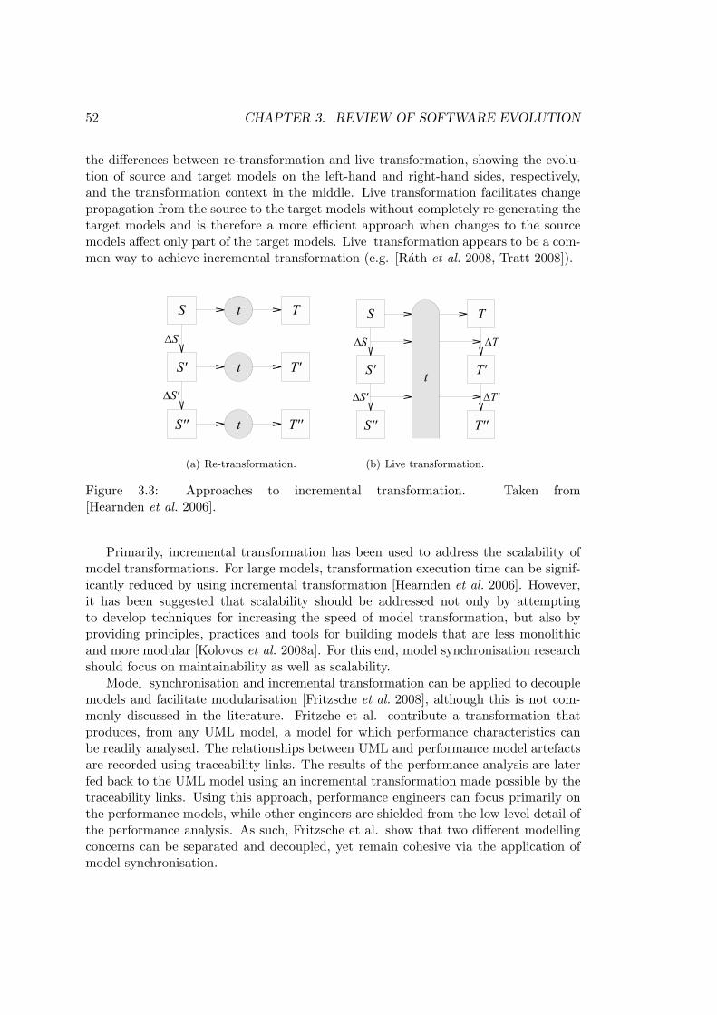
52 CHAPTER 3. REVIEW OF SOFTWARE EVOLUTION
the differences between re-transformation and live transformation, showing the evolu-tion of source and target models on the left-hand and right-hand sides, respectively,and the transformation context in the middle. Live transformation facilitates changepropagation from the source to the target models without completely re-generating thetarget models and is therefore a more efficient approach when changes to the sourcemodels affect only part of the target models. Live transformation appears to be a com-mon way to achieve incremental transformation (e.g. [Rath et al. 2008, Tratt 2008]).
322 D. Hearnden, M. Lawley, and K. Raymond
The second approach involves preserving the transformation context from theoriginal transformation, thus obviating a merge strategy to recreate it. A livetransformation does not terminate, rather it continuously maintains a transfor-mation context such that the effects of changes to source inputs can be readilyidentified, and the necessary recomputation performed.
Figure 1 illustrates these two approaches. In Figure 1(a), each successive up-date to S requires a complete re-transformation t producing new versions ofT . If in-situ updates are desired, then a merge is required. In Figure 1(b), thetransformation t is continuous, starting from an initial transformation from Sproducing T . Each successive source update ∆S is mapped directly to a targetupdate ∆T . The transformation t does not terminate as such, but rather goesthrough phases of activity when S is changed.
(a) Re-transformation (b) Live transformation
Fig. 1. Incremental Update Strategies
The advantage of the second approach is that it is far more efficient, especiallyfor small changes, and is thus more suitable for the rapid update of transforma-tion outputs. On average, the amount of computation necessary is proportionalto the size of the input changes and the output changes. This is particularlyimportant for model-driven tools in an incremental development methodology,where models are constantly evolving and constant synchronisation is neces-sary for consistency. Another advantage of the second approach is that it is amore direct solution for finding the changes to outputs required in response tochanges to inputs, as opposed to finding the actual outputs themselves. For amodel evolution tool, this may be an important distinction. Consider the task ofselecting, from a set of possible source changes under consideration, the changethat produces the smallest consequent change on the target models.
The cost of the second approach is that the execution context must be con-stantly maintained. Unless there are a large number of large transformationsbeing maintained, this is unlikely to be a significant problem, and section 3.1discusses how the space cost can be scalably traded for computation time shouldthe context become too large.
(a) Re-transformation.
322 D. Hearnden, M. Lawley, and K. Raymond
The second approach involves preserving the transformation context from theoriginal transformation, thus obviating a merge strategy to recreate it. A livetransformation does not terminate, rather it continuously maintains a transfor-mation context such that the effects of changes to source inputs can be readilyidentified, and the necessary recomputation performed.
Figure 1 illustrates these two approaches. In Figure 1(a), each successive up-date to S requires a complete re-transformation t producing new versions ofT . If in-situ updates are desired, then a merge is required. In Figure 1(b), thetransformation t is continuous, starting from an initial transformation from Sproducing T . Each successive source update ∆S is mapped directly to a targetupdate ∆T . The transformation t does not terminate as such, but rather goesthrough phases of activity when S is changed.
(a) Re-transformation (b) Live transformation
Fig. 1. Incremental Update Strategies
The advantage of the second approach is that it is far more efficient, especiallyfor small changes, and is thus more suitable for the rapid update of transforma-tion outputs. On average, the amount of computation necessary is proportionalto the size of the input changes and the output changes. This is particularlyimportant for model-driven tools in an incremental development methodology,where models are constantly evolving and constant synchronisation is neces-sary for consistency. Another advantage of the second approach is that it is amore direct solution for finding the changes to outputs required in response tochanges to inputs, as opposed to finding the actual outputs themselves. For amodel evolution tool, this may be an important distinction. Consider the task ofselecting, from a set of possible source changes under consideration, the changethat produces the smallest consequent change on the target models.
The cost of the second approach is that the execution context must be con-stantly maintained. Unless there are a large number of large transformationsbeing maintained, this is unlikely to be a significant problem, and section 3.1discusses how the space cost can be scalably traded for computation time shouldthe context become too large.
(b) Live transformation.
Figure 3.3: Approaches to incremental transformation. Taken from[Hearnden et al. 2006].
Primarily, incremental transformation has been used to address the scalability ofmodel transformations. For large models, transformation execution time can be signif-icantly reduced by using incremental transformation [Hearnden et al. 2006]. However,it has been suggested that scalability should be addressed not only by attemptingto develop techniques for increasing the speed of model transformation, but also byproviding principles, practices and tools for building models that are less monolithicand more modular [Kolovos et al. 2008a]. For this end, model synchronisation researchshould focus on maintainability as well as scalability.
Model synchronisation and incremental transformation can be applied to decouplemodels and facilitate modularisation [Fritzsche et al. 2008], although this is not com-monly discussed in the literature. Fritzche et al. contribute a transformation thatproduces, from any UML model, a model for which performance characteristics canbe readily analysed. The relationships between UML and performance model artefactsare recorded using traceability links. The results of the performance analysis are laterfed back to the UML model using an incremental transformation made possible by thetraceability links. Using this approach, performance engineers can focus primarily onthe performance models, while other engineers are shielded from the low-level detail ofthe performance analysis. As such, Fritzsche et al. show that two different modellingconcerns can be separated and decoupled, yet remain cohesive via the application ofmodel synchronisation.

3.2. SOFTWARE EVOLUTION IN PRACTICE 53
Towards automated model synchronisation Some existing work provides a foun-dation for automating model synchronisation activities. Theoretical aspects of thetraceability literature were reviewed in Section 3.1.5, and explored the automated ac-tivities that traceability facilitates, such as impact analysis and change propagation.This section now analyses the traceability research in the context of MDE and focuseson the way in which traceability facilitates the automation of model synchronisationactivities.
Aside from live transformation, other techniques for capturing trace links betweenmodels have been reported. To this end, a model-to-model transformation has beenenriched with traceability information using a generic higher-order transformation[Jouault 2005]. Given a transformation, the generic higher-order transformation addstransformation rules that produce a traceability model. In contrast to the genericityof the approach described by Jouault, Drivalos et al. propose domain-specific trace-ability metamodels for richer traceability link semantics [Drivalos et al. 2008]. Furtherresearch is required to assess the requirements of automated model synchronisationtools and to select appropriate traceability approaches for their implementation.
Impact analysis is used to reason about the effects of a change to a developmentartefact. As well as facilitating change propagation, impact analysis can help to predictthe cost and complexity of changes [Bohner 2002]. Impact analysis requires solutionsto several sub-problems, which include change detection, analysis of the effects of achange, and effective display of the analysis.
Impact analysis can be performed for UML models by comparing original andevolved versions of the same model to produce a report of evolved model elements thathave been impacted by the changes to the original model elements [Briand et al. 2003].To facilitate the impact analysis, Briand et al. identify change patterns that comprise,among other properties, a trigger (for change detection) and an impact rule (for markingmodel elements affected by this change). Figure 3.4 shows a sample impact analysispattern for UML sequence diagrams, which is triggered when a message is added, andmarks the sending class, the sending operation and the postcondition of the sendingoperation as impacted.
Only event-based approaches, such as the one described by Briand et al., havebeen proposed for automating impact analysis [Winkler & Pilgrim 2010]. Because ofthe use of patterns for detecting changes and specifying resulting actions, event-basedimpact analysis is similar to differencing approaches for schema evolution (for example,[Lerner 2000], which was discussed in Section 3.2.2). When more than one trigger mightapply, event-based impact analysis approaches must provide mechanisms for selectingbetween applicable patterns. The selection policy used by Briand et al. is implicit(cannot be changed by the user) and does not provide a mechanism for selecting betweenapplicable patterns.
Finally, model synchronisation tools might apply techniques used in automated syn-chronisation tools for traditional development environments. For example, the refactor-ing functionality of the Eclipse Java Development Tools [Fuhrer et al. 2007] propagateschanges between classes using a cache of the workspace to improve performance andscalability.

54 CHAPTER 3. REVIEW OF SOFTWARE EVOLUTION
!"#$%&'()*+&,! "#$%&'(!)'*+'%,'!-.$&/$0!1!2(('(!3'44$&'!!"#$%&'!-.&,! ")-523!!"#$%&.'/+&0&$*,! !"#$%&&'$()*+",-)%.%$!$/01&&2"%%)'"-)0+"/1&&3
4$5,$/2$6+)7-)!8+$931..&.'23-4&3*5,3 !"#$%&&'$()*+",-)%.%$!$/01&&2"%%)'"-)0+"/1&&:$11)7$3604#7*&.'/+&0&$*8,! !"#$%&&;",/#)0+"/&&2"-$&&<%)11<%)11+;+$-3
!"#$%&&;",/#)0+"/&&2"-$&&=>$-)0+"/3!"#$%&&;",/#)0+"/&&2"-$&&?"102"/#+0+"/3
9&873)4*)-$,'6#'!7$4'!,8$44!9:!;#'!,8$44.:.'/!/98'!;#$;!4'%(4!;#'!$(('(!0'44$&'!.4!.0<$,;'(=!6#'!9<'/$;.9%;#$;!4'%(4!;#'!$(('(!0'44$&'!.4!.0<$,;'(!$%(!.;4!<94;,9%(.;.9%!.4!$849!.0<$,;'(=!!
:#*)-$#+&,'6#'!4'%(.%&>49+/,'!,8$44!%9?!4'%(4!$!%'?!0'44$&'!$%(!9%'!9:!.;4!9<'/$;.9%4@!$,;+$88A!4'%(.%&!;#'!$(('(!0'44$&'@!.4!.0<$,;'(=!6#.4!9<'/$;.9%!.4!B%9?%!9/!%9;@!('<'%(.%&!9%!?#';#'/!;#'!0'44$&'!;/.&&'/.%&!;#'!$(('(!0'44$&'!,9//'4<9%(4!;9!$%!.%C9B'(!9<'/$;.9%=!D:@!:9/!'E$0<8'@!.;!.4!$!4.&%$8!;#'%!?'!0$A!%9;!B%9?!;#'!9<'/$;.9%@!F+4;!7A!899B.%&!$;!;#'!4'*+'%,'!(.$&/$0=!6#'!.0<$,;'(!<94;,9%(.;.9%!0$A!%9?!%9;!/'</'4'%;!;#'!'::',;!G?#$;!.4!;/+'!9%!,90<8';.9%H!9:!.;4!9<'/$;.9%=!
:&8;+*)$%'!"#$%&8,'6#'!.0<8'0'%;$;.9%!9:!;#'!7$4'!,8$44!0$A!#$C'!;9!7'!09(.:.'(=!6#'!0';#9(!9:!;#'!.0<$,;'(!9<'/$;.9%!0$A!#$C'!;9!7'!09(.:.'(=!6#'!.0<$,;'(!<94;,9%(.;.9%!4#9+8(!7'!,#',B'(!;9!'%4+/'!;#$;!.;!.4!4;.88!C$8.(=!
6$<-=&.':;+&,!"#$%&'(!"8$44!I<'/$;.9%!1!"#$%&'(!J94;,9%(.;.9%!G""I"J4;H!>!?'/@43&88)-$8,'context modelChanges::Change def:
let addedMessage:Message = self.changedElement.oclAsType(SequenceDiagramView). Message->select(m:Message | m.getIDStr()=self.propertyID)
let sendingOperation:Operation = ( if addedMessage.activator.action.oclIsTypeOf(CallAction) then
addedMessage.sender.base.operation->select(o:Operation | o.equals(addedMessage.activator.callAction.operation))
else null
endif) context modelChanges::Change – class
addedMessage.sender.base context modelChanges::Change – operation
sendingOperation context modelChanges::Change – postcondition
sendingOperation.postcondition
A)%;3&'B'C'604#7*'1$#+58)8':;+&'/@#04+&'
D%!9+/!'E$0<8'@!;#'!,#$%&'(!</9<'/;A!.4!$%!$(('(!0'44$&'!.%!;#'!SequenceDiagramView=!
6#'%@! ;#'! 9<'/$;.9%! ;#$;! <944.78A! 4'%(4! ;#'! $(('(!0'44$&'! .4! .('%;.:.'(=!K9;'! ;#$;! ;#'!
%$C.&$;.9%!'E</'44.9%! :./4;! .('%;.:.'4! ;#'!7$4'!,8$44!9:! ;#'!,8$44.:.'/! /98'L! ;#$;! 4'%(4! ;#'!
$(('(!0'44$&'4@!$4!?'!?$%;!;9!.('%;.:A!;#'!9<'/$;.9%!$4!('4,/.7'(!.%!;#'!,8$44!(.$&/$0@!
$%(!%9;!;#'!9<'/$;.9%!$4!.;!.4!+4'(!.%!;#'!4'*+'%,'!(.$&/$0M=!6#.4!.('%;.:.,$;.9%!.%C98C'4!
4'8',;.%&!G;#'!select!9<'/$;9/H!;#'!0';#9(!(',8$/$;.9%!.%!;#'!,8$44!;#$;!,9//'4<9%(4!;9!;#'!!!!!!!!!!!!!!!!!!!!!!!!!!!!!!!!!!!!!!!!!!!!!!!!!!!!!!!!!!!!M!D%!;#.4!,$4'@!;#'!%$C.&$;.9%!.4!4.0<8AN!addedMessage.activator.callAction.operation=!24!.%!;#'!9::.,.$8!O3P!0';$Q09('8@!9<'/$;.9%!.%C9,$;.9%4!$%(!(',8$/$;.9%4!$/'!09('8'(!7A!;#'!4$0'!=>$-)0+"/!,8$44=!!
RS!
Figure 3.4: Example impact analysis pattern, taken from [Briand et al. 2003].
Synchronisation of models with text and trace links So far, this section hasconcentrated on model-to-model synchronisation, which is facilitated by traceability.Traceability is important for other software evolution activities in a model-driven devel-opment environment – such as synchronisation between models and text and betweenmodels and trace links – and these activities are now discussed.
While most of the model synchronisation literature focuses on synchronising mod-els with other models, some papers consider synchronisation between models and othertypes of artefact. For synchronising changes in requirements documents with mod-els, there is abundance of work in the field of requirements engineering, where theneed for traceability was first reported. For synchronising models with generated text(during code generation, for example), the model-to-text language, Epsilon Gener-ation Language (EGL) [Rose et al. 2008b], produces traceability links between codegeneration templates and generated files. Sections of code can be marked protected,

3.2. SOFTWARE EVOLUTION IN PRACTICE 55
and are not overwritten by subsequent invocations of the code generation template.The MOFScript model-to-text language, like EGL, provides protected sections. Un-like EGL, MOFScript stores traceability links in a structured manner, facilitating im-pact analysis, model coverage (for highlighting which areas of the model contributeto the generated code) and orphan analysis (for detecting invalid traceability links)[Olsen & Oldevik 2007].
Trace links can be affected when development artefacts change. Synchronisationtools rely on accurate trace links and hence the maintenance of trace links is important.It has been suggested that trace versioning should be used to address the challengesof trace link maintenance [Winkler & Pilgrim 2010], which include the accidental in-clusion of unintended dependencies as well as the exclusion of necessary dependencies.Furthermore, Winkler and von Pilgrim note that, although versioning traces has beenexplored in specialised areas (such as hypermedia [Nguyen et al. 2005]), there is noholistic approach for versioning traces.
Model-metamodel Co-Evolution
A metamodel describes the structures and rules for a family of models. When a modeluses the structures and adheres to the rules defined by a metamodel, the model is saidto conform to the metamodel [Bezivin 2005]. A change to a metamodel might requirechanges to models to ensure the preservation of conformance. The process of evolving ametamodel and its models together to preserve conformance is termed model-metamodelco-evolution and is subsequently referred to as co-evolution. This section exploresexisting approaches to co-evolution, comparing them with work from the closely relatedareas of schema and grammar evolution approaches (Sections 3.2.2 and 3.2.3). A morethorough analysis of co-evolution approaches is conducted in Chapter 4.
Co-evolution theory A co-evolution process involves changing a metamodel andupdating instance models to preserve conformance. Often, the two activities are con-sidered separately, and the latter is termed migration. In this thesis, the term migrationstrategy is used to mean an algorithm that specifies migration. Sprinkle and Karsaiwere the first to identify the need for approaches that consider the specific requirementsof co-evolution [Sprinkle & Karsai 2004]. In particular, Sprinkle and Karsai describemigration as distinct from – and as having unique challenges compared to – the moregeneral activity of model-to-model transformation. The phrase “evolution, not revolu-tion” has been used to highlight and emphasise that, during co-evolution, the differencebetween source and target metamodels is often small [Sprinkle 2003].
Understanding the situations in which co-evolution must be managed is importantfor formulating appropriate requirements for co-evolution tools. Migration is some-times made unnecessary by evolving a metamodel such that the conformance of modelsis not affected (e.g. making only additive changes) [Herrmannsdoerfer et al. 2009a].Co-evolution can be carried out by more than one person, and in some cases metamodeldevelopers and model users might not communicate [Cicchetti et al. 2008]. Notwith-

56 CHAPTER 3. REVIEW OF SOFTWARE EVOLUTION
standing these observations, the co-evolution literature rarely reports on the ways inwhich co-evolution is managed in practice.
Co-evolution patterns Much of the co-evolution literature suggests that the mi-gration process should vary depending on the type of metamodel changes made (forexample [Gruschko et al. 2007, Cicchetti et al. 2008]). In particular, the co-evolutionliterature identifies two important classifications of metamodel changes that affect theway in which migration is performed. Depending on the type of metamodel change, mi-gration might be unnecessary (non-breaking change), can be automated (breaking andresolvable change) and can be automated only when ambiguity is resolved by a devel-oper (breaking and non-resolvable change) [Gruschko et al. 2007]. Metamodel changescan also be regarded as either metamodel-independent (observed in the evolution ofmore than one metamodel) or metamodel-specific (observed in the evolution of onlyone metamodel) [Herrmannsdoerfer et al. 2008a].
Further research is needed to identify categories of metamodel changes, becausemany automated co-evolution approaches are underpinned by the categorisations. Al-though it has been suggested that a large proportion of metamodel changes re-occur[Herrmannsdoerfer et al. 2008a], the study in which this claim was made considers onlytwo metamodels, both taken from the same organisation. Assessing the extent to whichchanges re-occur across a larger and broader range of metamodels is an open researchchallenge to which this thesis contributes, particularly in Chapter 4.
Co-evolution approaches Several approaches for managing co-evolution have beenproposed, most of which are based on one of the two classifications of metamodelchanges described above.
Re-use of migration knowledge is a primary concern in the work of Herrmannsdorfer,which is premised on an observation that a large proportion of metamodel changes re-occurred during the development of two metamodels [Herrmannsdoerfer et al. 2008a].COPE [Herrmannsdoerfer et al. 2009a] is a co-evolution tool that provides a library ofco-evolutionary operators. Operators are applied to evolve a metamodel and have pre-defined migration semantics. The application of each operator is recorded, and used togenerate an executable migration strategy. Due to its use of re-usable operators, COPEshares characteristics with operator-based approaches for schema and grammar evolu-tion (Sections 3.2.2 and 3.2.3). Consequently, the limitations of operator-based schemaevolution approaches [Lerner 2000] apply to COPE. Balancing expressiveness and un-derstandability is a key challenge for operator-based approaches because the formerimplies a large number of operators while the latter a small number of operators.
Gruschko et al. suggest inferring co-evolution strategies, based on either a differ-ence model of two versions of the evolving metamodel (direct comparison) or on alist of changes recorded during the evolution of a metamodel (indirect comparison)[Gruschko et al. 2007]. To this end, Gruschko et al contribute the co-evolution processshown in Figure 3.5.
Two inference approaches inspired by the work of Gruschko et al. are now de-

3.2. SOFTWARE EVOLUTION IN PRACTICE 57
Figure 3.5: The co-evolution process described in [Gruschko et al. 2007].
scribed. Both approaches use a co-evolution process similar to the one shown in Figure3.5, and use higher-order model transformation5 for determining the migration strategy(the penultimate phase in Figure 3.5). Cicchetti et al. contribute a metamodel for de-scribing the similarities and differences between two versions of a metamodel, enabling amodel-driven approach to generating model migration strategies [Cicchetti et al. 2008].Garces et al. provide a similar metamodel, but use a metamodel matching processthat can be customised by the user, who specifies matching heuristics to form a match-ing strategy [Garces et al. 2009]. Otherwise, the co-evolution approaches described byCicchetti et al. and Garces et al. are fully automatic and cannot be guided by theuser. Clearly then, accuracy is important for approaches that compare two metamodelversions, but Cicchetti et al. and Garces et al. do not explore the extent to which theproposed approaches can be applied.
Some co-evolution approaches predate the classifications of metamodel changes de-scribed above. For instance, an initial catalogue of metamodel changes was the first toemploy higher-order transformation for specifying model migration [Wachsmuth 2007].However, Wachsmuth considers a small number of metamodel changes occurring inisolation and, as such, it is not clear whether the approach can be used in the generalcase. Sprinkle proposes a visual transformation language for specifying model mi-gration based on graph transformation theory [Sprinkle 2003], which is less expressivethan imperative or hybrid transformation languages (as discussed in Section 2.1.4).
5A model-to-model transformation that consumes or produces a model-to-model transformation ishigher-order.

58 CHAPTER 3. REVIEW OF SOFTWARE EVOLUTION
Visualisation
To better understand the effects of evolution on development artefacts, visualisingdifferent versions of each artefact may be beneficial. Existing research for comparingtext can be enhanced to perform semantic-differencing of models with a textual concretesyntax. For models with a visual concrete syntax, another approach is required.
To visualise the way in which model elements are transformed by transforma-tion chains (the sequential composition of model-to-model transformations), a three-dimensional editor has been implemented [Pilgrim et al. 2008]. Figure 3.6 depicts asample transformation chain visualisation. Each plane represents a model. The linksbetween each plane illustrates the effects of a model-to-model transformation. Thevisualisation style used in the three-dimensional editor could be used to facilitate ex-ploration of artefact evolution.
Figure 3.6: Visualising a transformation chain. Taken from [Pilgrim et al. 2008].
Summary Fully automated migration remains an open research challenge. Co-evolution approaches are in their infancy, and key problems need to be addressed.For example, matching schemas (metamodels) can yield more than one feasible set ofmigration strategies [Lerner 2000]. To this end, matching heuristics, which guide theinference of the model migration strategy – but might affect the predictability of theco-evolution process – have been proposed [Garces et al. 2009].

3.3. CHALLENGES TO MANAGING EVOLUTION IN MDE 59
Another open research challenge is in identifying an appropriate notation for de-scribing migration. Existing tools have used general-purpose programming languages[Herrmannsdoerfer et al. 2009a] or higher-order model-to-model (M2M) transforma-tions [Wachsmuth 2007, Cicchetti et al. 2008]. Migration is a specialisation of M2Mtransformation [Sprinkle & Karsai 2004], and therefore languages other than M2Mtransformation languages might be more suitable for describing migration.
Until co-evolution tools reach maturity, improving MDE modelling frameworks tobetter support co-evolution is necessary. For example, EMF (Section 2.3.1) cannotload models that no longer conform to their metamodel and, hence non-conformantmodels cannot be loaded in model editors, and cannot be used with model managementoperations.
This section has surveyed the existing work on identifying and managing softwareevolution in the context of MDE. In particular, several types of evolutionary change tomodelling artefacts have been identified. Chapter 4 provides a more detailed and criticalanalysis of the work described in this section. In particular, Section 4.2 comparesdifferent approaches to managing co-evolution using an example from an MDE project.
3.3 Challenges to Managing Software Evolution in MDE
From the review presented above, several research challenges for managing softwareevolution in the context of MDE are synthesised. The challenges summarised in thissection were considered as possible research directions for the thesis research.
Model refactoring challenges The model refactoring literature proposes tools andtechniques for improving the quality of existing models without affecting their func-tional behaviour. In traditional development environments, inter-artefact refactoring(in which changes span more than one development artefact) is often automated, butnone of the model refactoring papers discussed in this chapter consider inter-modelrefactoring. In general, the refactoring literature covers several concerns, such as identi-fication, validation and assessment (Section 3.1.3), but the model refactoring literatureconsiders only the specification and application of refactoring. To better understandthe costs and benefits of model refactoring, further model refactoring research mustalso explore the identification, validation and assessment of model refactorings.
Model synchronisation challenges Improved scalability is the primary motiva-tion of most model synchronisation research, although it has been suggested that modelsynchronisation can be used to improve the maintainability of a system via modulari-sation [Fritzsche et al. 2008]. Consequently, further research should explore the extentto which model synchronisation can be used to manage evolution. For impact analysisbetween models, only event-based approaches have been reported; other approaches– used successfully to manage evolution in other fields (such as relational databasesand grammarware) – have not been applied to models [Winkler & Pilgrim 2010]. Few

60 CHAPTER 3. REVIEW OF SOFTWARE EVOLUTION
papers consider synchronisation with other artefacts and maintaining trace links andthere is potential for further research in these areas.
Co-evolution challenges To better understand and to more thoroughly investi-gate model-metamodel co-evolution, further studies of the ways in which metamodelschange are required. The existing empirical study of metamodel evolution in industry[Herrmannsdoerfer et al. 2008a] focuses only on two metamodels produced in the sameorganisation. Challenges for co-evolution reported in other fields have not been ad-dressed by the model-metamodel co-evolution literature. For example, comparing twoversions of a changed artefact (such as metamodel) can suggest more than one feasi-ble migration strategy [Lerner 2000]. This challenge must be addressed by approachesto co-evolution that do not consider the way in which a metamodel has changed (e.g.[Cicchetti et al. 2008, Garces et al. 2009]). A range of notations are used for model mi-gration, including M2M transformation languages and general-purpose programminglanguages, which is a challenge for the comparison of co-evolution tools. Finally, con-temporary MDE modelling frameworks do not facilitate MDE for non-conformant mod-els, which is problematic at least until co-evolution tools reach maturity.
General challenges for evolution in MDE From the analysis in this chapter,several research challenges for software evolution in the context of MDE are apparent.Greater understanding of the situations in which evolution occurs informs the iden-tification and management of evolution, yet few papers study evolution in real-worldMDE projects. Analysis of existing projects can yield patterns of evolution, providing acommon vocabulary for thinking and communicating about evolution. These patternsare used as a foundation for notations and tools used to automate some evolution activ-ities. In addition, recording, analysing and visualising changes made over the long termto MDE development artefacts and to MDE projects is an area that is not consideredin the literature.
3.4 Chapter Summary
This chapter has reviewed and analysed software evolution literature. Two evolutionactivities explored in the remainder of this thesis, impact analysis and change prop-agation, were introduced. Principles and practices of software evolution (from thefields of programming languages, relational database systems and grammarware) werecompared and analysed. In particular, software evolution literature from the MDEcommunity was reviewed and analysed to allow the synthesis of research challengesand potential directions for the thesis research.
As well as directing the thesis research, the literature review influenced the choiceof research method (Section 1.4.2). Most of the software evolution research discusseduses a similar method (e.g. [Guerrini et al. 2005, Kramer 2001, Su et al. 2001] for XMLschema evolution and [Banerjee et al. 1987, Edelweiss & Moreira 2005] for relationaldatabase schema evolution): first, identify and categorise evolutionary changes by con-

3.4. CHAPTER SUMMARY 61
sidering all of the ways in which artefacts can change. Next, design a taxonomy ofoperators that capture these changes or a matching algorithm that detects the applica-tion of the changes. Then, implement a tool for applying operators, invoking a matchingalgorithm, or trigger change events. Finally, evaluate the tool on existing projects con-taining examples of evolution. This method assumes that most (if not all) evolutionarychanges can be identified and captured from existing examples of evolution, and doesnot consider the ways in which evolution is already managed in existing projects. Analternative method was used to conduct the thesis research, which was discussed inSection 1.4.2 and based on the method used by Dig in his work on program refactoring([Dig 2007]). First, existing projects were analysed to better understand the situationsin which evolution occurs. From this analysis, research requirements were derived, andstructures and processes for managing evolution were implemented. The structures andprocesses were evaluated by comparison with related structures and processes, and byapplication to real-world MDE projects in which evolution had occurred. This methodwas preferred as existing work on evolution in MDE (Section 3.2.4) does not considerthe way in which evolution is managed in existing MDE projects, and, with the excep-tion of COPE [Herrmannsdoerfer et al. 2009a], can only be used to manage a fixed setof evolutionary changes.
The review and the research challenges presented in this chapter led to a criticalanalysis of techniques for identifying and managing evolution in the context of softwareevolution. Chapter 4 presents the critical analysis, which was conducted using examplesfrom real-world MDE projects.


Chapter 4
MDE and Evolution: ProblemAnalysis
The review presented in Chapter 3 highlighted challenges for identifying and managingevolution in the context of MDE, and noted that little work has explored the way inwhich evolution occurs in practice. This chapter explores evolution in the context ofMDE by identifying and analysing examples from software engineering projects de-veloped in a model-driven manner. The research method, outlined in Sections 1.4.2and 3.4, comprises three phases: analysis, implementation and evaluation. This chap-ter describes the first phase, and presents the requirements that were identified for theimplementation and evaluation phases.
Figure 4.1 summarises the work presented in this chapter. Examples of evolutionin MDE projects were located from real-world MDE projects and additional sources(Section 4.1). The examples of evolution were used to analyse existing co-evolutiontechniques, which led to a categorisation and comparison of existing co-evolution ap-proaches (Section 4.2) and to the identification of modelling framework characteristicsthat restrict the way in which co-evolution can be managed (Section 4.2.1). Researchrequirements for this thesis were identified from the analysis presented in this chapter(Section 4.3).
Figure 4.1: Analysis chapter overview.
63

64 CHAPTER 4. MDE AND EVOLUTION: PROBLEM ANALYSIS
4.1 Examples of Evolution from MDE Projects
In Chapter 3, three categories of evolutionary change were identified: model refactoring,synchronisation and co-evolution. Existing MDE projects were examined for examplesof synchronisation and co-evolution and, due to time constraints, examples of modelrefactoring were not considered. The examples were used to provide requirements fordeveloping structures and processes for evolutionary changes in the context of MDE.In this section, the requirements used to select example data are described, along withcandidate and selected MDE projects. The section concludes with a discussion offurther examples, which were obtained from joint research – with colleagues in thisdepartment and at the University of Kent – and from related work on the evolution ofobject-oriented programs.
4.1.1 Requirements
The suitability of each MDE project for analysing co-evolution and for analysing modelsynchronisation was determined using a set of requirements. The requirements werepartitioned into: common requirements (needed to analyse both model synchronisationand co-evolution), requirements for studying model co-evolution, and requirementsfor studying synchronisation. Candidate MDE projects were evaluated against theserequirements, and several were selected for further analysis.
Common requirements
Every project needs to use MDE (requirement R1), as the analysis investigated evo-lution in the context of MDE. Metamodelling and model transformation are two fun-damental activities in MDE, as discussed in Section 2.1, and, as such, a project wasdeemed as using MDE when evidence of both metamodelling and model transformationwas encountered.
Every project needs to provide historical information of development artefacts (R2),as the analysis investigated the evolution of development artefacts. For example, severalversions of a project are needed, perhaps stored in a source code management system.
Every project needs to have undergone significant evolutionary change1 (R3). Sometypes of evolution have little impact on other artefacts (adding a non-mandatory at-tribute to a class, for example), are not costly, and, hence, do not require dedicatedstructures and processes for their management.
Co-evolution requirements
Every project for the study of co-evolution needs to define a metamodel and somechanges to that metamodel (R4), as co-evolution is the process of evolving a model inresponse to metamodel changes. In the projects considered, the metamodel changes
1This is deliberately vague. Further details are given in Section 4.1.2.

4.1. EXAMPLES OF EVOLUTION FROM MDE PROJECTS 65
took the form of either another version of the metamodel, or a history (which recordedeach of the steps used to produce the adapted metamodel)
Every project also needs to provide example instances of models before and aftereach migration activity (R5), as the way in which a model should be evolved during co-evolution is not always apparent from the metamodel changes. When a class is deletedfrom a metamodel, for example, models might be evolved such that all instances ofthe deleted class are also deleted, or such that all instances of the deleted class have adifferent type.
Ideally, every project will include more than one metamodel change in sequence,so as to represent the way in which the same development artefacts continue to evolveover time (optional requirement O1).
Synchronisation requirements
Every project for the study of synchronisation needs to define a model-to-model trans-formation (R6), as model synchronisation is the process of propagating changes betweentwo models, and typically uses a model-to-model transformation to define the relation-ship between the two models.
Every project needs to provide examples of the kinds of change (to either source ortarget model) that cause inconsistency between the models (R7), so as to investigate theway in which models have changed in the context of the project (rather than investigatechanges that might not have occurred in practice).
Ideally, every project will include transformation chains (more than one model-to-model transformation, executed sequentially) (O2), because chains of transformationsare prescribed by the MDA guidelines [Kleppe et al. 2003], and hence model synchroni-sation tools might be required to propagate changes over a transformation chain (ratherthan over a single transformation).
4.1.2 Project Selection
Eight candidate projects were considered for the analysis presented in this chapter.Table 4.1 shows which of the requirements are met by each of the candidates. Eachcandidate is now discussed in turn.
GSN
The Goal Structuring Notation (GSN) [Kelly 1999] is a notation for specifying safetyarguments. Georgios Despotou and Tim Kelly, members of this department’s HighIntegrity Systems Engineering group, are constructing a metamodel for Goal Struc-turing Notation (GSN). The metamodel has been developed incrementally. There isno accurate and detailed version history for the GSN metamodel (requirement R2).Suitability for study: Unsuitable.

66 CHAPTER 4. MDE AND EVOLUTION: PROBLEM ANALYSIS
NameRequirements
Common Co-evolution SynchronisationR1 R2 R3 R4 R5 O1 R6 R7 O2
GSN x xOMG x x xZoos x x xMDT x x x x
MODELPLEX x x x x x xFPTC x x x x xXtext x x x x x x x xGMF x x x x x x x x
Table 4.1: Candidates for study of evolution in existing MDE projects
OMG MDE Projects
The Object Management Group (OMG)2 oversees the development of model-driventechnologies. Andrew Watson, the Vice President and Technical Director of OMG,oversaw the development of two MDE projects [Watson 2008]. Personal correspondencewith Watson ascertained that source code is available for one of the projects, but thereis no version history. Suitability for study: Unsuitable.
Zoos
A zoo is a collection of metamodels, authored in a common metamodelling language.Two zoos were considered (the Atlantic Zoo and the AtlantEcore Zoo3), but neithercontained significant metamodel changes. Those changes that were recorded involvedonly renaming of meta-classes (trivial to migrate) or additive changes, which do notaffect conformance and therefore require no migration. Suitability for study: Un-suitable.
MDT
The Eclipse Model Development Tools (MDT)4 provides implementations of industry-standard metamodels, such as UML2 [OMG 2007a] and OCL [OMG 2006]. Like themetamodel zoos, the version history for the MDT metamodels contained no significantchanges. Suitability for study: Unsuitable.
2http://www.omg.org3Both have moved to: http://www.emn.fr/z-info/atlanmod/index.php/Zoos4http://www.eclipse.org/mdt

4.1. EXAMPLES OF EVOLUTION FROM MDE PROJECTS 67
MODELPLEX
Jendrik Johannes, a Research Assistant at TU Dresden, has made available work fromthe European project, MODELPLEX5. Johannes’s work involves transforming UMLmodels to Tool Independent Performance Models (TIPM) for simulation. Although theTIPM metamodel and the UML-to-TIPM transformation have been changed signifi-cantly, no significant changes have been made to the models. The TIPM metamodel waschanged such that conformance was not affected. Suitability for study: Unsuitable.
FPTC
Failure Propagation and Transformation Calculus (FPTC) [Wallace 2005], developedby Malcolm Wallace in this department, provides a means for reasoning about thefailure behaviour of complex systems. In an earlier project, Richard Paige and theauthor developed an implementation of FPTC in Eclipse [Paige et al. 2009]. The im-plementation includes an FPTC metamodel. More recent work with Philippa Conmy,a Research Associate in this department, has identified a significant flaw in the imple-mentation, leading to changes to the metamodel. The metamodel changes affected theconformance of existing FPTC models. Conmy has made available copies of FPTCmodels from before and after the changes. Suitability for study: Suitable for study-ing co-evolution. Unsuitable for studying synchronisation, because, although the toolincludes a transformation, the target models are produced as output from a simulation,never stored and hence do not become inconsistent with their source model.
Xtext
Xtext6 is used to generate parsers, metamodels and editors for performing text-to-model transformation, and was introduced in Section 2.1.4. Internally, Xtext defines ametamodel, which was changed significantly between 2006 and 2008. In several cases,changes have affected conformance. Xtext provides examples, which have been updatedalongside the metamodel. Xtext uses model-to-model transformation to generate mod-els, which are later disregarded and hence do not need to be synchronised with sourcemodels. Suitability for study: Suitable for studying co-evolution. Unsuitable forstudying synchronisation.
GMF
The Graphical Modelling Framework (GMF) [Gronback 2009] allows the definition ofgraphical concrete syntax for metamodels that have been defined in EMF, and wasintroduced in Section 2.3.1. GMF prescribes a model-driven approach: users of GMFdefine concrete syntax as a model, which is used to generate a graphical editor. In fact,five models are used together to define a single editor using GMF.
5Grant number IST 34081, http://www.modelplex.org/6http://www.eclipse.org/Xtext/

68 CHAPTER 4. MDE AND EVOLUTION: PROBLEM ANALYSIS
GMF defines the metamodels for graphical, tooling and mapping definition mod-els; and for generator models. The metamodels have changed considerably during thedevelopment of GMF. Some changes have affected the conformance of existing GMFmodels. Presently, migration is encoded in Java. Gronback has stated7 that the mi-gration code is being ported to QVT (a model-to-model transformation language) asthe Java code is difficult to maintain.
GMF meets almost all of the requirements for the study. Co-evolution data isavailable, including migration strategies. The GMF source code repository does notcontain examples of the kinds of change that cause inconsistency between the models(R7). Suitability for study: Suitable for studying co-evolution. Unsuitable forstudying synchronisation.
Summary of selection
Of the eight projects considered, three (FPTC, Xtext and GMF) met all of the require-ments for studying co-evolution. No project met all of the requirements for studyingsynchronisation, and, consequently, data was sought from other sources as discussedbelow. FPTC and Xtext were used to perform the analysis described in the remain-der of this chapter, along with examples taken from other sources. GMF providesthe most comprehensive examples of co-evolution, as it includes several metamodelsthat have undergone two major and several minor revisions, several exemplar modelsthat have been migrated, and reference migration strategies (written in Java). Ratherthan use GMF for analysis, it was instead reserved for evaluation of the thesis research(Chapter 6).
4.1.3 Other examples
Since few existing MDE projects met all of the requirements for studying evolution,additional data was sought from alternative sources. Examples were located fromobject-oriented systems – which have some similarities to systems developed usingMDE – and via collaboration with colleagues on two projects, both of which involveddeveloping a system using MDE.
Examples of evolution from object-oriented software
Object-oriented programming and metamodelling have some commonalities. In object-oriented programming, software is constructed by developing groups of related objects.Every object is an instance of (at least) one class. A class is a description of character-istics, which is shared by each of the class’s instances (objects). A similar relationshipexists between models and metamodels: metamodels comprise meta-classes, which de-scribe the characteristics shared by each of the meta-class’s instances (elements of amodel). Together, model elements are used to describe one perspective (model) of a sys-tem. This similarity between object-oriented programming and metamodelling implied
7Private communication, 2008.

4.1. EXAMPLES OF EVOLUTION FROM MDE PROJECTS 69
that the evolution of object-oriented systems may be similar to evolution occurring inMDE.
Refactoring is the process of improving the structure of existing code while main-taining its external behaviour. When used as a noun, a refactoring is one such im-provement. As discussed in Chapter 3, refactoring of object-oriented systems has beenwidely studied, perhaps most notably in [Fowler 1999], which provides a catalogue ofrefactorings for object-oriented systems. For each refactoring, Fowler gives advice andinstructions for its application.
To explore their relevance to MDE, Fowler’s refactorings have been applied to meta-models. Some have been found to be relevant to metamodels, and could potential occurduring MDE. Many have been found to be irrelevant, belonging to one of the followingthree categories:
1. Operational refactorings focus on restructuring behaviour (method bodies).Most modelling frameworks do not support the specification of behaviour in mod-els.
2. Navigational refactorings affect navigational constructs are specified, such aschanging between bi- and uni-directional associations. These changes are oftennon-breaking in modelling frameworks, which typically infer values for the inverseof a reference when required.
3. Domain-specific refactorings manage issues not relevant to metamodels, suchas casting, defensive return values, and assertions.
The object-oriented refactorings that can be applied to metamodels provide ex-amples of metamodel evolution and, in some cases, have the potential to affect con-formance. For each refactoring that affected conformance, a migration strategy wasdeduced by the author using Fowler’s description of each refactoring. An example ofthis process is now presented.
Figure 4.2 illustrates a refactoring that changes a reference object to a value object[Fowler 1999][pg183]. Value objects are immutable, and cannot be shared (i.e. anytwo objects cannot refer to the same value object). By contrast, reference objects aremutable, and can be shared. Figure 4.2 indicates that applying the refactoring restrictsthe multiplicity of the association (on the Order end) to 1 (implied by the composition);prior to the refactoring the multiplicity is many-valued.
Before applying the refactoring, each customer may be associated with more thanone order. After the refactoring, each customer should be associated with only oneorder. Fowler indicates that every customer associated with more than one order shouldbe duplicated, such that one customer object exists for each order. Therefore, themigration strategy in Listing 4.1 is deduced. Using this process, migration strategieswere deduced for each of the refactorings that were applicable to metamodels andaffected conformance.
1 for every customer, c
2 for every order, o, associated with c

70 CHAPTER 4. MDE AND EVOLUTION: PROBLEM ANALYSIS
Figure 4.2: Refactoring a reference to a value. Taken from [Fowler 1999, pg183].
3 create a new customer, d
4 copy the values of c’s attributes into d
5 next o
6
7 delete c
8 next c
Listing 4.1: Pseudo code migration strategy for the refactoring in Figure 4.2
The examples of metamodel evolution based on Fowler’s refactorings provided addi-tional data for deriving research requirements. Some parts of the metamodel evolutionsfrom existing MDE projects were later found to be equivalent to Fowler’s refactorings,which, to some extent, validates the above claim that evolution from object-orientedsystems can be used to reason about metamodel evolution.
However, object-oriented refactorings are used to improve the maintainability ofexisting systems. In other words, they represent only one of the three common reasonsfor evolutionary change (Section 3.1.1). The two other types of change – for addressingnew requirements and facilitating interoperability with other systems – are equallyrelevant for deriving research requirements, and so object-oriented refactorings aloneare not sufficient for reasoning about metamodel evolution.
Research collaborations
As well as the example data located from object-oriented systems, collaboration onprojects using MDE with two colleagues provided several examples of evolution. Agraphical editor for process-oriented programs was developed with Adam Sampson,then a Research Associate at the University of Kent, and is described in Appendix B.Additionally, the feasibility of a tool for generating story-worlds for interactive nar-ratives was investigated with Heather Barber, then a postdoctoral researcher in thisdepartment.
In both cases, a metamodel was constructed for describing concepts in the do-main. The metamodels were developed incrementally and changed over time. The

4.2. AN ANALYSIS OF EXISTING CO-EVOLUTION TECHNIQUES 71
collaborations with Sampson and Barber did not involve constructing model-to-modeltransformations, but did provide data suitable for a study of co-evolution.
The majority of the changes made in both of these projects relate to changing re-quirements. In each iteration, existing requirements were refined and new requirementsdiscovered. Neither project required changes to support architectural restructuring. Inaddition, the work undertaken with Sampson included some changes to adapt the sys-tem for use with a different technology than originally anticipated. That is to say, thechanges observed represented two of the three common reasons for evolutionary change(Section 3.1.1).
4.1.4 Summary
This section has described the identification of examples for analysing the way in whichevolution is identified and managed in the context of MDE. Example data was soughtfrom existing MDE projects, a related domain (refactoring of object-oriented systems)and collaborative work on MDE projects (with Sampson and Barber). Eight MDEprojects were located, three of which satisfied the requirements for a study of co-evolutionary changes in the context of model-driven engineering. One of the threeprojects, GMF, was reserved for the evaluation presented in Chapter 6. Refactorings ofobject-oriented programming supplemented the data available from the existing MDEprojects. Collaboration with Sampson and Barber yielded further examples of co-evolution.
The lack of examples of model synchronisation might indicate that model synchro-nisation is not an important evolutionary activity for MDE. An alternative explanationis that, in 2008, many projects were beginning to adopt MDE principles, but had nottransitioned to a fully model-driven style of development. It has been suggested thatMDE is adopted in an incremental manner and that model transformations are spec-ified only after models are first used in an ad-hoc manner and MDE is applied toautomate simple tasks [Rios et al. 2006]. Regular, empirical assessment is necessary toinvestigate the adoption of MDE and the need to support evolutionary activities, suchas model synchronisation. Due to the lack of examples of model synchronisation, theremainder of the thesis focuses on model-metamodel co-evolution.
4.2 An Analysis of Existing Co-Evolution Techniques
The examples of co-evolution identified in the Section 4.1 were analysed to identifyand compare existing techniques for managing co-evolution. This section discusses theresults of analysing the examples; namely a deeper understanding of modelling frame-work characteristics that affect the management of co-evolution (Section 4.2.1), anda categorisation of existing techniques for managing co-evolution (Sections 4.2.2 and4.2.3). The work presented here was published in [Rose et al. 2009b, Rose et al. 2009a].

72 CHAPTER 4. MDE AND EVOLUTION: PROBLEM ANALYSIS
4.2.1 Modelling Framework Characteristics
The co-evolution examples identified in Section 4.1 were examined to understand theways in which co-evolution is managed in practice. The examination of co-evolutionexamples highlighted characteristics of MDE development environments that affect theway in which co-evolution can be managed. The characteristics are now described.
Model-Metamodel Separation
In MDE development environments, models and metamodels are separated. Metamod-els are developed and distributed to users. Metamodels are installed, configured andcombined to form a customised MDE development environment. Metamodel developershave no programmatic access to instance models, which reside in a different workspaceand potentially on a different machine. Consequently, metamodel evolution occurs in-dependently to model migration. Figure 4.3 shows the activities typically involved inco-evolution. First, the metamodel developer evolves the metamodel and may create amigration strategy. Subsequently, the metamodel users discover conformance problemsafter installing the new version of the metamodel, and migrate their models.
Metamodel developer Metamodel user
Evolve metamodel
Create migration strategy
Install new metamodel version
Find conformance problems
Migrate models
Figure 4.3: Co-evolution activities
Due to model and metamodel separation, co-evolution is either developer-driven(the metamodel developer devises an executable migration strategy, which is distributedto the metamodel user with the evolved metamodel) or user-driven (the metamodeldeveloper provides no migration strategy). In either case, model migration occurs onthe machine of the metamodel user, after and independent of metamodel evolution.
Implicit Conformance
MDE development environments implicitly enforce conformance. A model is boundto its metamodel, typically by constructing a representation in the underlying pro-gramming language for each model element and data value. Frequently, binding is

4.2. AN ANALYSIS OF EXISTING CO-EVOLUTION TECHNIQUES 73
strongly-typed: each metamodel type is mapped to a corresponding type in the under-lying programming language using mappings defined by the metamodel. Consequently,modelling frameworks do not permit changes to a model that would cause it to nolonger conform to its metamodel. Loading a model that does not conform to its meta-model causes an error. In short, MDE modelling frameworks cannot be used to managemodels that do not conform to their metamodel.
Because modelling frameworks can only load models that conform to their meta-model, user-driven co-evolution is always a manual process, in which models are mi-grated without using the modelling framework. Typically then, the metamodel usercan only perform migration by editing the model directly, normally manipulating itsunderlying representation (e.g. XMI). Model editors and model management opera-tions, which are ordinarily integral to MDE, cannot be used to manage models that donot conform to their metamodel and hence, cannot be used during model migration.
A further consequence of implicitly enforced conformance is that modelling toolsmust produce models that conform to their metamodel, and therefore, model migrationcannot be decomposed. Consequently, model migration cannot be performed by com-bining co-evolution techniques, because intermediate steps must produce conformantmodels.
4.2.2 User-Driven Co-Evolution
Examples of co-evolution were analysed to discover and compare existing techniques formanaging co-evolution. As discussed above, the separation of models and metamodelsleads to two processes for co-evolution: developer-driven and user-driven. Analysisof the co-evolution examples identified in Section 4.1 highlighted several instances ofuser-driven co-evolution. Projects conducted in collaboration with Barber and withSampson involved user-driven co-evolution, and all of the co-evolution examples takenfrom the Xtext project were managed in a user-driven manner. This section demon-strates user-driven co-evolution using a scenario similar to one observed during thecollaboration with Barber.
In user-driven co-evolution, the metamodel user performs migration by loading theirmodels to test conformance, and then reconciling conformance problems by updatingnon-conformant models. The metamodel developer might guide migration by providinga migration strategy to the metamodel user. Crucially, however, the migration strategyis not executable (e.g. it is written in prose). This is the key distinction betweenuser-driven and developer-driven co-evolution. Only in the latter does the metamodeldeveloper provided an executable model migration strategy.
In some cases, the metamodel user will not be provided with any migration strategy(executable or otherwise) from the metamodel developer. To perform migration, themetamodel user must determine which (if any) model elements no longer conform tothe evolved metamodel, and then decide how best to change non-conformant elementsto re-establish conformance.

74 CHAPTER 4. MDE AND EVOLUTION: PROBLEM ANALYSIS
Attempt to load model with
graphical editor
Does EMF report any conformance problems?
No
YesEdit XMI of
non-conformant model
Figure 4.4: User-driven co-evolution with EMF
User-driven co-evolution in EMF
EMF (Section 2.3.1) provides structures and processes for loading, storing and editingmodels and metamodels. When a model no longer conforms to its metamodel, however,the model cannot be loaded, cannot be used with EMF’s model editors, and cannotbe used with model management operations. Therefore, model migration must beperformed manually, typically by editing the underlying storage representation of themodel.
A typical workflow for performing user-driven co-evolution with EMF is shown inFigure 4.4. (The workflow in Figure 4.4 assumes a graphical model editor, such as thosegenerated by GMF, but any model editor that is built on EMF will exhibit the samebehaviour). When the user attempts to load a model, EMF automatically checks theconformance of the model with respect to its metamodel. When the model does notconform to its metamodel, EMF reports (some of the) conformance errors, loading failsand the model is not displayed in the graphical editor. To re-establish conformance, theuser must edit by hand the underlying storage representation of the model, XMI. Aftersaving the reconciled XMI to disk, the user attempts to load the model in the graphicaleditor again. If the user makes a mistake in reconciling the XMI, loading will fail againand further conformance errors will be reported. Even if the user makes no mistakes inreconciling the XMI, further conformance errors might be reported because EMF usesa multi-pass XMI parser and cannot report all categories of conformance problem inone pass of the XMI. If further conformance problems are reported, the user continuesto reconcile the XMI by hand. Otherwise, migration is complete and the model isdisplayed in the graphical editor.
Scenario The following scenario demonstrates user-driven co-evolution. Markis developing a metamodel. Members of his team, including Heather, install Mark’s

4.2. AN ANALYSIS OF EXISTING CO-EVOLUTION TECHNIQUES 75
metamodel and begin constructing models. Mark later identifies new requirements,changes the metamodel, builds a new version of the metamodel, and distributes itto his colleagues.
After several iterations of metamodel updates, Heather tries to load one of herolder models, constructed using an earlier version of Mark’s metamodel. Whenloading the older model, the modelling framework reports an error indicating thatthe model no longer conforms to its metamodel. To load the older model, Heathermust reinstall the version of the metamodel to which the older model conforms.But even then, the modelling framework will bind the older model to the old versionof the metamodel, and not to the evolved metamodel.
Employing user-driven co-evolution, Heather must trace and repair the load-ing error directly in the model as it is stored on disk. Model storage formatshave typically been optimised to either reduce the size of models on disk or toimprove the speed of random access to model elements. Therefore, human usabil-ity is not a key requirement for model storage formats. XMI, for example, is astandard model storage format and is regarded as sub-optimal for use by humans[OMG 2004]. Consequently, using a model storage format to perform model migra-tion can be error-prone and tedious. When directly editing the underlying formatof a model, reconciling conformance is often a slow and iterative process. WithEMF [Steinberg et al. 2008], for example, user-driven co-evolution is an iterativeprocess as shown in Figure 4.4. When models are persisted in a database (perhapsfor scalability reasons), a binary rather than a textual storage representation isused, further impeding user-driven co-evolution. For example, models stored usingthe Connected Data Objects Model Repository (CDO)8 are persisted in a rela-tional database, which must be manipulated when non-conformant models are tobe edited.
Challenges
The scenario (in the box above) highlights the two most significant challenges facedwhen performing user-driven co-evolution. Firstly, the underlying model representationis unlikely to be optimised for human usability and hence user-driven co-evolution iserror-prone and tedious. Secondly, although conformance can be affected when a newversion of a metamodel is installed, conformance problems are not reported to theuser as part of the installation process. These challenges are further elaborated in theSection 4.3, which identifies research requirements.
It is worth noting that the above scenario describes a metamodel with only oneuser. Some metamodels – such as UML, Ecore, and MOF – have many more users, anduser-driven co-evolution would require repeated manual effort from each user. In spiteof this, UML, for example, does not provide a strategy for migrating between versions
8http://www.eclipse.org/cdo/

76 CHAPTER 4. MDE AND EVOLUTION: PROBLEM ANALYSIS
of the specification, and users must infer the migration semantics from changes to thespecification.
4.2.3 Developer-Driven Co-Evolution Approaches
In developer-driven co-evolution, the metamodel developer provides an executable mi-gration strategy along with the evolved metamodel. Model migration might be sched-uled automatically by the modelling framework (for example when a model is loaded)or by the metamodel user.
As noted in Section 4.2.2, co-evolution research focuses on developer-driven ratherthan user-driven co-evolution. Several developer-driven co-evolution approaches werereviewed in Section 3.2.4. To compare and categorise existing developer-driven co-evolution approaches, the approaches have been applied by the author to the co-evolution examples identified in Section 4.1. From this analysis and from the literaturereview conducted in Section 3.2.4, three categories of developer-driven co-evolutionapproach were identified: manual specification, operator-based and inference. The cat-egorisation has been published in [Rose et al. 2009b]. Each category is now discussed.
Manual Specification
In manual specification, the migration strategy is encoded manually by the metamodeldeveloper, typically using a general purpose programming language (e.g. Java) orone of the model-to-model transformation languages described in Section 2.1.4. Themigration strategy can manipulate instances of the metamodel in any way permitted bythe modelling framework. Manual specification approaches have been used to managemigration in GMF (Section 2.3.1) and in the Eclipse MDT UML2 project, which wereoutlined in Section 4.1. Compared to operator-based and inference techniques (below),manual specification permits the metamodel developer the most control over modelmigration.
However, manual specification generally requires the most effort on the part of themetamodel developer for two reasons. Firstly, as well as implementing the migrationstrategy, the metamodel developer must also produce code for executing the migrationstrategy. Typically, this involves integration of the migration strategy with the mod-elling framework (to load and store models) and possibly with development tools (toprovide a user interface). Secondly, frequently occurring model migration patterns –such as copying a model element from original to migrated model – are not capturedby existing general purpose and model-to-model transformation languages, and so eachmetamodel developer has to codify migration patterns in their chosen language.
Operator-based
In operator-based co-evolution techniques, a library of co-evolutionary operators is pro-vided. Each co-evolutionary operator specifies a metamodel evolution along with acorresponding model migration strategy. For example, the “Make Reference Contain-ment” operator might evolve the metamodel such that a non-containment reference be-

4.2. AN ANALYSIS OF EXISTING CO-EVOLUTION TECHNIQUES 77
comes a containment reference and migrate models such that the values of the evolvedreference are replaced by copies. By composing co-evolutionary operators, metamodelevolution can be performed and a migration strategy can be generated without writ-ing any code. Operator-based approaches for schema evolution and co-evolution weredescribed in Sections 3.2.2 and 3.2.4. In particular, a library of co-evolutionary op-erators for MOF metamodels has been described in [Wachsmuth 2007], and COPE[Herrmannsdoerfer et al. 2009a] is an operator-based co-evolution approach for EMF.
The efficacy of an operator-based co-evolution approach depends heavily on therichness of its library of co-evolutionary operators. When no operator describes therequired co-evolution pattern, the metamodel developer must use another approachfor performing model migration. For instance, COPE allows migration to be specifiedmanually with a general purpose programming language when no co-evolutionary op-erator is appropriate. (Consequently, custom migration strategies in COPE suffer oneof the same limitations as manual specification approaches: model migration patternsare not captured in the language used to specify migration strategies).
As using co-evolutionary operators to express migration require the metamodeldeveloper to write no code, it seems that operator-based co-evolution approaches shouldseek to provide a large library of co-evolutionary operators, so that at least one operatoris appropriate for every co-evolution pattern that a metamodel developer may wish toapply. However, as discussed in Section 3.2.2, a large library of operators increasesthe complexity of specifying migration. To demonstrate, Lerner considers moving afeature from one type to another. This could be expressed by sequential applicationof two operators called, for example, delete feature and add feature. However,the semantics of a delete feature operator are likely to dictate that the valuesof that feature will be removed during migration and hence, delete feature isunsuitable when specifying that a feature has been moved. To solve this problem, amove feature operator could be introduced, but then the metamodel developer mustunderstand the difference between the two ways in which moving a type can be achieved,and carefully select the correct one. Lerner provides other examples which furtherelucidate this issue (such as introducing a new type by splitting an existing type). Asthe size of the library of co-evolutionary operators grows, so does the complexity ofselecting appropriate operators and, hence, the complexity of performing metamodelevolution.
Clear communication of the effects of each co-evolutionary operator (on both themetamodel and its instance models) can improve the navigability of large libraries ofco-evolutionary operators. COPE, for example, provides a name, description, list ofparameters and applicability constraints for each co-evolutionary operator. An exampleis shown in Figure 4.5. To choose between operators, users can read descriptions (suchas the one shown below) examine the source code of the operator, or try executing theoperator (an undo command is provided).
Finding a balance between richness and navigability is a key challenge in defin-ing libraries of co-evolutionary operators for operation-based co-evolution approaches.Analogously, a known challenge in the design of software interfaces is the trade-offbetween a rich and a concise interface [Bloch 2005].

78 CHAPTER 4. MDE AND EVOLUTION: PROBLEM ANALYSIS
Make Reference ContainmentIn the metamodel, a reference is made [into a] containment. In the model, its valuesare replaced by copies.Parameters:
• reference: The reference
Constraints:
• The reference must not already be containment.
Figure 4.5: Make Reference Containment operation, taken from COPE[Herrmannsdoerfer et al. 2009a].
To perform metamodel evolution using co-evolutionary operators, the library of co-evolutionary operators must be integrated with tools for editing metamodels. COPE,for instance, provides integration with the EMF tree-based metamodel editor. However,some developers edit their metamodels using a textual syntax, such as Emfatic9. Ingeneral, freeform text editing is less restrictive than tree-based editing (because in thelatter, the metamodel is always structurally sound whereas in the former, the textdoes not always have to compile). Consequently, it is not clear whether operator-basedco-evolution can be used with all categories of metamodel editing tool.
Inference
In inference approaches, a migration strategy is derived from the evolved metamodeland the metamodel history. Inference approaches can be further categorised accordingto the type of metamodel history used. Differencing approaches compare and matchthe original and evolved metamodels, while change recording approaches use a recordof primitive changes made to the original metamodel to produce the evolved meta-model. The analysis of the evolved metamodel and the metamodel history yields adifference model [Cicchetti et al. 2008], a representation of the changes between orig-inal and evolved metamodel. The difference model is used to infer a migration strat-egy, typically by using a higher-order model-to-model transformation10 to producea model-to-model transformation from the difference model. Cicchetti et al. andGarces et al. describe differencing-based inference approaches [Cicchetti et al. 2008,Garces et al. 2009]. There exist no pure change recording approaches, although COPE[Herrmannsdoerfer et al. 2009a] uses change recording for the specification of custom
9http://www.alphaworks.ibm.com/tech/emfatic10A model-to-model transformation that consumes or produces a model-to-model transformation is
termed a higher-order model transformation.

4.2. AN ANALYSIS OF EXISTING CO-EVOLUTION TECHNIQUES 79
model migration strategies, and Mendez et al. suggest that a change recording approachmight be used to manage metamodel-transformation co-evolution [Mendez et al. 2010].
Compared to manual specification and operator-based co-evolution approaches, in-ference approaches require the least amount of effort from the metamodel developerwho needs only to evolve the metamodel and provide a metamodel history. However,for some types of metamodel change, there is more than one feasible model migrationstrategy. For example, when a metaclass is deleted, one feasible migration strategy is todelete all instances of the deleted metaclass. Alternatively, the type of each instance ofthe deleted metaclass could be changed to another metaclass that specifies equivalentstructural features.
To select the most appropriate migration strategy from all feasible alternatives,an inference approach often requires guidance, because the metamodel changes alonedo not provide enough information to correctly distinguish between feasible migrationstrategies. Existing inference approaches use heuristics to determine the most appro-priate migration strategy. These heuristics sometimes lead to the selection of the wrongmigration strategy.
Because inference approaches use heuristics to select a migration strategy, it cansometimes be difficult to reason about which migration strategy will be selected. Fordomains where predictability, completeness and correctness are a primary concern (e.g.safety critical or security critical systems, or systems that must undergo certificationwith respect to a relevant standard), such approaches are unsuitable, and deterministicapproaches that can be demonstrated to produce correct, predictable results will berequired.
The two types of inference approach – differencing and change recording – are nowcompared, using an example of co-evolution, introduced below.
Example The following example was observed during the development of the EpsilonFPTC tool [Paige et al. 2009] (which was summarised in Section 4.1). The source codeis available from EpsilonLabs11. Figure 4.6(a) illustrates the original metamodel inwhich a System comprises any number of Blocks. A Block has a name, and anynumber of successor Blocks; predecessors is the inverse of the successorsreference.
Further analysis of the domain revealed that extra information about the rela-tionship between Blocks was to be captured. The evolved metamodel is shown inFigure 4.6(b). The Connection class is introduced to capture the extra informationvia its literalsText attribute. Blocks are no longer related directly to Blocks,instead they are related via an instance of the Connection class. The incomingCo-nnections and outgoingConnections references of Block are used to relateBlocks to each other via an instance of Connection.
A model that conforms to the original metamodel (Figure 4.6(a)) might not conformto the evolved metamodel (Figure 4.6(b)). Below is a description of the strategy used
11http://sourceforge.net/projects/epsilonlabs/

80 CHAPTER 4. MDE AND EVOLUTION: PROBLEM ANALYSIS
(a) Original metamodel, prior to evolution
(b) Evolved metamodel with Connection metaclass
Figure 4.6: Metamodel evolution in the Epsilon FPTC tool. Taken from[Rose et al. 2009b].
by the Epsilon FPTC tool to migrate a model from original to evolved metamodel andis taken from [Rose et al. 2009b]:
1. For every instance, b, of Block:
For every successor, s, of b:
Create a new instance, c, of Connection.
Set b as the source of c.
Set s as the target of c.
Add c to the connections of the System containing b.
2. And nothing else changes.
Using the example described above, differencing and change recording inferenceapproaches are now compared.
Change recording In change recording approaches, metamodel evolution is mon-itored by a tool, which records a list of primitive changes (e.g. Add class namedConnection, Change the type of feature successors from Block to Connection).The record of changes may be reduced to a normal form to remove redundancy, butdoing so can erase useful information. In change recording, some types of metamodel
4.2. AN ANALYSIS OF EXISTING CO-EVOLUTION TECHNIQUES 81
evolution can be more easily recognised than with differencing. With change record-ing, renaming can be distinguished from a deletion followed by an addition. Withdifferencing, this distinction is not possible.
In general, more than one combination of primitive changes can be used to achievethe same metamodel evolution. However, when recording changes, the way in which ametamodel is evolved affects the inference of migration strategy. In the example pre-sented above, the outgoingConnections reference (shown in Figure 4.6(b)) couldhave been produced by changing the name and type of the successors reference(shown in Figure 4.6(a)). In this case, the record of changes would indicate that thenew outgoingConnections reference is an evolution of the successors reference,and consequently an inferred migration strategy would be likely to migrate values ofsuccessors to values of outgoingConnections. Alternatively, the metamodeldeveloper may have elected to delete the successors reference and then create theoutgoingConnections reference afresh. In this record of changes, it is less obviousthat the migration strategy should attempt to migrate values of successors to val-ues of outgoingConnections. Clearly then, change recording approaches requirethe metamodel developer to consider the way in which their metamodel changes willbe interpreted.
Change recording approaches require facilities for monitoring metamodel changesfrom the metamodel editing tool, and from the underlying modelling framework. Aswith operation-based co-evolution, it is not clear to what extent change recording canbe supported when a textual syntax is used to evolve a metamodel. A further challengeis that the granularity of the metamodel changes that can be monitored influences theinference of the migration strategy, but this granularity is likely to be controlled byand specific to the implementation of the metamodelling language. Normal forms towhich a record of changes can be reduced have been proposed to address this issue[Cicchetti 2008].
Differencing In differencing approaches, the original and evolved metamodels arecompared to produce the difference model. Unlike change recording, metamodel evo-lution may be performed using any metamodel editor; there is no need to monitor theprimitive changes made to perform the metamodel evolution. However, as discussedabove, not recording the primitive changes can cause some categories of change tobecome indistinguishable, such as renaming versus a deletion followed by an addition.
To illustrate this problem further, consider again the metamodel evolution describedabove. A comparison of the original (Figure 4.6(a)) and evolved (Figure 4.6(b)) meta-models shows that the references named successors and predecessors no longerexist on Block. However, two other references, named outgoingConnections andincomingConnections, are now present on Block. A differencing approach mightdeduce (correctly, in this case) that the two new references are evolutions of the oldreferences. However, no differencing approach is able to determine which mapping iscorrect from the following two possibilities:
• successors evolved to incomingConnections; predecessors evolved to
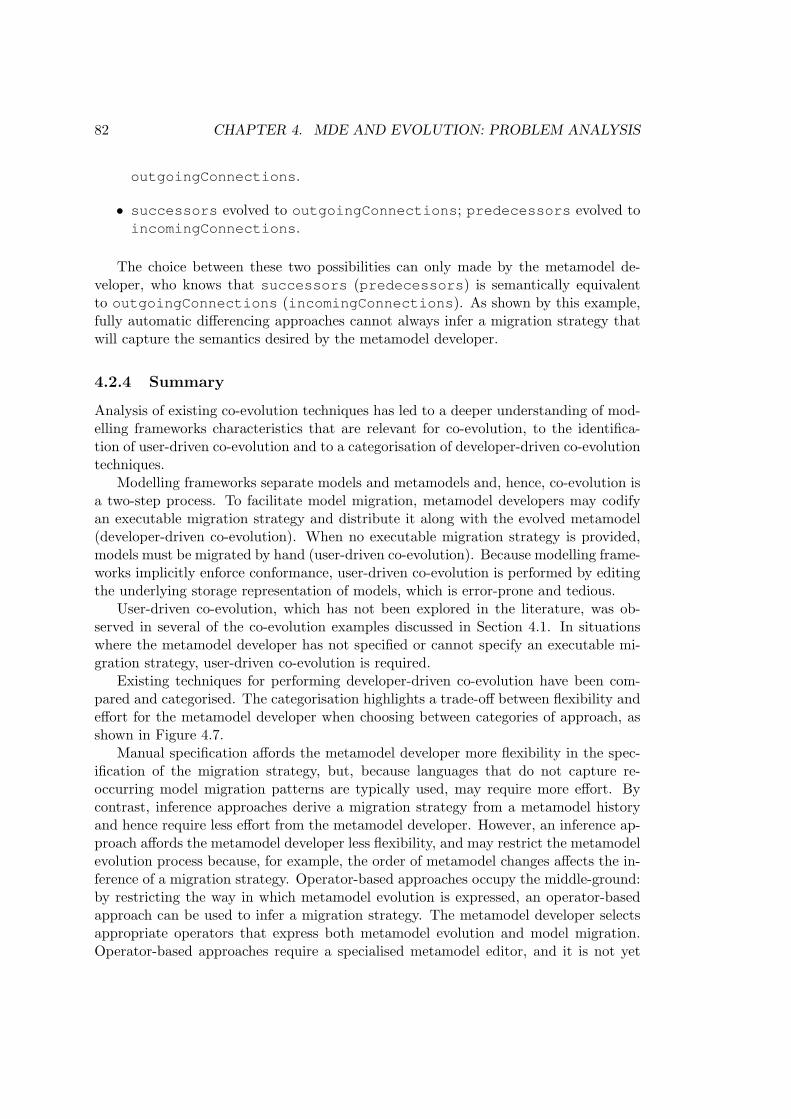
82 CHAPTER 4. MDE AND EVOLUTION: PROBLEM ANALYSIS
outgoingConnections.
• successors evolved to outgoingConnections; predecessors evolved toincomingConnections.
The choice between these two possibilities can only made by the metamodel de-veloper, who knows that successors (predecessors) is semantically equivalentto outgoingConnections (incomingConnections). As shown by this example,fully automatic differencing approaches cannot always infer a migration strategy thatwill capture the semantics desired by the metamodel developer.
4.2.4 Summary
Analysis of existing co-evolution techniques has led to a deeper understanding of mod-elling frameworks characteristics that are relevant for co-evolution, to the identifica-tion of user-driven co-evolution and to a categorisation of developer-driven co-evolutiontechniques.
Modelling frameworks separate models and metamodels and, hence, co-evolution isa two-step process. To facilitate model migration, metamodel developers may codifyan executable migration strategy and distribute it along with the evolved metamodel(developer-driven co-evolution). When no executable migration strategy is provided,models must be migrated by hand (user-driven co-evolution). Because modelling frame-works implicitly enforce conformance, user-driven co-evolution is performed by editingthe underlying storage representation of models, which is error-prone and tedious.
User-driven co-evolution, which has not been explored in the literature, was ob-served in several of the co-evolution examples discussed in Section 4.1. In situationswhere the metamodel developer has not specified or cannot specify an executable mi-gration strategy, user-driven co-evolution is required.
Existing techniques for performing developer-driven co-evolution have been com-pared and categorised. The categorisation highlights a trade-off between flexibility andeffort for the metamodel developer when choosing between categories of approach, asshown in Figure 4.7.
Manual specification affords the metamodel developer more flexibility in the spec-ification of the migration strategy, but, because languages that do not capture re-occurring model migration patterns are typically used, may require more effort. Bycontrast, inference approaches derive a migration strategy from a metamodel historyand hence require less effort from the metamodel developer. However, an inference ap-proach affords the metamodel developer less flexibility, and may restrict the metamodelevolution process because, for example, the order of metamodel changes affects the in-ference of a migration strategy. Operator-based approaches occupy the middle-ground:by restricting the way in which metamodel evolution is expressed, an operator-basedapproach can be used to infer a migration strategy. The metamodel developer selectsappropriate operators that express both metamodel evolution and model migration.Operator-based approaches require a specialised metamodel editor, and it is not yet

4.3. REQUIREMENTS FOR CO-EVOLUTION 83
Figure 4.7: Spectrum of developer-driven co-evolution approaches
clear whether they can be applied when a metamodel is represented with a freeform(e.g. textual) rather than a structured (e.g. tree-based) syntax.
4.3 Requirements for Identifying and ManagingCo-Evolution
The analysis presented throughout this chapter has highlighted a number of challengesfor identifying and managing model-metamodel co-evolution. Several factors affectand restrict the way in which co-evolution is performed in practice. The way in whichmodelling frameworks are implemented affect the ways in which the impact analysis andpropagation of metamodel changes can be performed. Existing co-evolution approachesare developer-driven rather than user-driven (i.e. assume that the metamodel developerwill provide a migration strategy), which was not the case for several of the examplesidentified in Section 4.1. Additionally, the languages used to specify model migrationvary over existing co-evolution approaches, which inhibits the conceptual and practicalre-use of model migration patterns. This section contributes requirements for structuresand processes that seek to address these challenges.
Below, the thesis requirements are presented in three parts. The first identifiesrequirements that seek to extend and enhance support for managing model and meta-model co-evolution with modelling frameworks. The second summarises and identi-fies requirements for enhancing the user-driven co-evolution process discussed in Sec-tion 4.2.2. Finally, the third identifies requirements that seek to improve the spectrumof existing developer-driven co-evolution techniques.
4.3.1 Explicit conformance checking
Section 4.2.1 discussed characteristics of modelling frameworks relevant to managingco-evolution. Because modelling frameworks typically enforce model and metamodelconformance implicitly, they cannot be used to load non-conformant models. Con-

84 CHAPTER 4. MDE AND EVOLUTION: PROBLEM ANALYSIS
sequently, user-driven co-evolution involves editing a model in its storage representa-tion, which is error-prone and tedious, because human usability is not normally a keyrequirement for model storage representations. Furthermore, modelling frameworksthat implicitly enforce conformance understandably provide little support for explic-itly checking the conformance of a model with other metamodels (or other versions ofthe same metamodel). As discussed in Section 4.2.1, explicit conformance checking isuseful for impact analysis activities, such as determining whether a model needs to bemigrated during the installation of a newer version of its metamodel.
Therefore, the following requirement was derived: This thesis must investigate theextension of existing modelling frameworks to support the loading of non-conformantmodels and conformance checking of models against other metamodels.
4.3.2 User-driven co-evolution
When a metamodel change will affect conformance in only a small number of mod-els, a metamodel developer may decide that the extra effort required to specify anexecutable migration strategy is too great, and prefer a user-driven co-evolution tech-nique. Section 4.2.2 introduced – and highlighted several challenges for – user-drivenco-evolution.
Because modelling frameworks typically cannot be used to load models that do notconform to their metamodel, user-driven co-evolution involves editing the storage rep-resentation of a model. As discussed above, model storage representations are typicallynot optimised for human use and hence user-driven co-evolution can be error-prone andtime consuming. When a multi-pass parser is used to load models (as is the case withEMF), user-driven co-evolution is an iterative process, because not all conformanceerrors are reported at once.
Therefore, the following requirement was derived: This thesis must demonstratea user-driven co-evolution process that enables the editing of non-conformant modelswithout directly manipulating the underlying storage representation and provides a con-formance report for the original model and evolved metamodel.
4.3.3 Developer-driven co-evolution
The comparison of developer-driven co-evolution techniques (Section 4.2.3) highlightsvariation in the languages used for codifying model migration strategies. More specif-ically, the model migration strategy languages varied in their scope (general-purposeprogramming languages versus model transformation languages) and category of typesystem. Furthermore, the amount of processing performed when executing a modelmigration strategy also varied: some techniques only load a model, execute the modelmigration strategy using an existing execution engine and store the model, while othersperform significant processing in addition to the computation specified in the model mi-gration strategy. COPE, for example, transforms models to a metamodel-independentrepresentation before migration is executed, and back to a metamodel-specific repre-sentation afterwards.

4.4. CHAPTER SUMMARY 85
Of the three categories of developer-driven co-evolution technique identified in Sec-tion 4.2.3, only manual specification (in which the metamodel developer specifies themigration strategy by hand) always requires the use of a migration strategy language.Nevertheless, both operator-based and inference approaches might utilise a migrationstrategy language in particular circumstances. Some operator-based approaches, suchas COPE, permit manual specification of a model migration strategy when no co-evolutionary operator is appropriate. For describing the effects of co-evolutionary op-erators, the model migration part of an operator could be described using a modelmigration strategy language. When an inference approach suggests more than onefeasible migration strategy, a migration strategy language could be used to presentalternatives to the metamodel developer. To some extent then, the choice of modelmigration strategy language influences the efficacy of all categories of developer-drivenco-evolution approach.
Given the variations in existing model migration strategy languages and the in-fluence of those languages on developer-driven co-evolution, the following requirementwas derived: This thesis must compare and evaluate existing languages for specifyingmodel migration strategies.
As discussed in Section 4.2.3, existing manual specification techniques do not pro-vide model migration strategy languages that capture patterns specific to model mi-gration. Developers must re-invent solutions to commonly occurring model migrationpatterns, such as copying an element from the original to the migrated model. In somecases, manual specification techniques require the developer to implement, in additionto a migration strategy, mechanisms for loading and storing models and for interfacingwith the metamodel user.
Devising a domain-specific languages or DSL (discussed in Chapter 3) is one ap-proach to capturing re-occurring patterns, and executable DSLs are widely used forspecifying and performing model management in contemporary model-driven develop-ment environments. Contemporary model management tools provide many executableDSLs for model transformation, validation, merging, weaving, and many other modelmanagement tasks (Section 2.1.4).
Given the apparent appropriateness of a domain-specific language for specifyingmodel migration and that no common language for specifying migration has yet beendevised, the following requirement was derived: This thesis must implement and evalu-ate a domain-specific language for specifying and executing model migration strategies,comparing it to existing languages for specifying model migration strategies.
4.4 Chapter Summary
The literature review performed in Chapter 3 identified several types of evolution thatoccur in MDE projects, including model refactoring, synchronisation and co-evolution.Although several papers propose structures and processes for managing evolution inMDE, little work has considered the way in which MDE artefacts evolve in practice.The work described in this chapter has investigated evolution in existing MDE projects,

86 CHAPTER 4. MDE AND EVOLUTION: PROBLEM ANALYSIS
culminating in a deeper understanding of the conceptual and technical issues faced whenidentifying and managing co-evolution. Furthermore, the analysis has facilitated thederivation of requirements for structures and processes that will address several of thechallenges to identifying and managing co-evolution today.
Examples of co-evolution were identified from real-world MDE projects, and supple-mentary data was located by examining a related area (refactoring in object-orientedsystems) and from collaborative work on two projects using MDE. The examples wereused to understand how co-evolution is performed in practice, and led to the identifica-tion of user-driven co-evolution. Furthermore, the examples were used to analyse andcategorise existing approaches to managing co-evolution.
Examining the co-evolution examples and applying existing co-evolution tools to theexamples led to several observations. Firstly, modelling frameworks restrict the way inwhich co-evolution can be identified and managed. Secondly, user-driven co-evolution(in which models are migrated without an executable strategy) occurs in practice, butno existing co-evolution tools provide support for it. Finally, the variation of languagesused for specifying model migration inhibits the re-use of commonly occurring patterns.
From the analysis performed in this chapter, requirements for the implementationphase of the thesis were formulated. The structures and process developed to approachthose requirements are described in Chapter 5, and seek to alleviate the restrictionsof modelling frameworks, to improve and support user-driven co-evolution (which iscurrently error-prone and tedious), and to provide a common language for specifyingmodel migration.
Chapter 5
Design and Implementation
Section 4.3 presented requirements for structures and processes for identifying and man-aging co-evolution. This chapter describes the way in which the requirements have beenaddressed. Several related structures have been implemented, using domain-specificlanguages, metamodelling and model management operations. Figure 5.1 summarisesthe contents of the chapter. To facilitate the management of non-conformant mod-els with existing modelling frameworks, a metamodel-independent syntax was devisedand implemented (Section 5.1). To address some of the challenges faced in user-drivenco-evolution, an OMG specification for a textual modelling notation was implemented(Section 5.2). Finally, a model transformation language – tailored for model migrationand centred around a novel approach to relating source and target model elements –was designed and implemented (Sections 5.3 and 5.4).
Figure 5.1: Implementation chapter overview.
The structures presented in this chapter are interoperable as shown in Figure 5.2. Inparticular, the modelling framework extensions of the metamodel-independent syntaxare used to provide conformance checking for the textual modelling notation, and toenable conformance checking for the model migration language. The structures wereseparated to facilitate re-use of the conformance checking services provided by themetamodel-independent syntax. Table 5.1 shows the relationship between the proposedstructures and the thesis requirements (Section 4.3).
87

88 CHAPTER 5. DESIGN AND IMPLEMENTATION
Developer-drivenco-evolution
User-drivenco-evolution
Textual modelling notation Model migration language
Metamodel-independent syntax
uses uses
Figure 5.2: The relationships between the proposed structures
Structure (Section) Requirement
Metamodel-independent syntax (5.1)
This thesis must investigate theextension of existing modellingframeworks to support the loadingof non-conformant models andconformance checking of modelsagainst other metamodels.
Textual modelling notation (5.2)
This thesis must demonstrate auser-driven co-evolution processthat enables the editing ofnon-conformant models withoutdirectly manipulating theunderlying storage representationand provides a conformance reportfor the original model andevolved metamodel.
Model migration language (5.3)
This thesis must compare andevaluate existing languagesfor specifying modelmigration strategies.
Model migration language (5.4)
This thesis must implement andevaluate a domain-specificlanguage for specifying andexecuting model migrationstrategies, comparing it toexisting languages for specifyingmodel migration strategies.
Table 5.1: The relationship between the thesis requirements and the proposed struc-tures

5.1. A METAMODEL-INDEPENDENT SYNTAX 89
5.1 A Metamodel-Independent Syntax
Section 4.2.1 discussed the way in which modelling frameworks implicitly enforce con-formance, and hence prevent the loading of non-conformant models. Additionally,modelling frameworks provide little support for checking the conformance of a modelwith other versions of a metamodel, which is potentially useful during metamodelinstallation. In Section 4.3, these concerns led to the identification of the following re-quirement: This thesis must investigate the extension of existing modelling frameworksto support the loading of non-conformant models and conformance checking of modelsagainst other metamodels.
This section describes the way in which existing modelling frameworks load andstore models using metamodel-specific binding mechanisms, proposes an alternativebinding mechanism using a metamodel-independent syntax, and demonstrates howthis facilitates automatic consistency checking. The work presented in this section hasbeen published in [Rose et al. 2009a].
(a) Original metamodel.
(b) Evolved metamodel.
Figure 5.3: Evolution of a families metamodel, based on the metamodel in [OMG 2004].

90 CHAPTER 5. DESIGN AND IMPLEMENTATION
5.1.1 Metamodel Evolution Example: Families
This section uses the example of metamodel evolution in Figure 5.3. The metamodels inFigure 5.3 have been constructed in Ecore, the metamodelling language of EMF, whichis based on MOF (Section 2.1.3). The metamodels use Ecore types such as EStringand EFloat. The nuclear attribute on the Family type is used to indicate that thefamily “comprises only a father, a mother, and children” [Merriam-Webster 2010], andnot extended family members (such as cousins or grandparents).
In Figure 5.3(a), naturalChildren and adoptedChildren are modelled asseparate features, and, in Figure 5.3(b), they are modelled as a single feature, chil-dren. Models that specify values for the naturalChildren or adoptedChildrenfeatures do not conform to the evolved metamodel. For example, the model in Fig-ure 5.4 represents a Family comprising two Persons, conforms to the original meta-model, and does not conform to the evolved metamodel. Using the families metamodeland model, the sequel explains why existing modelling frameworks cannot be used toload non-conformant models.
Figure 5.4: A family model, which conforms to the metamodel in Figure 5.3(a), in anEMF tree editor
5.1.2 Binding to a Specific Metamodel
To load a model, existing modelling frameworks construct objects in the underlyingprogramming language in a process termed binding (Section 4.2.1). The metamodeldefines the way in which model elements will be bound, and binding is strongly-typed.Figure 5.5 illustrates the results of binding the family model in Figure 5.4 to the originalfamilies metamodel in Figure 5.3(a). The objects in Figure 5.5 instantiate types thatare defined in the metamodel, such as Family and Person. In other words, bindingresults in a metamodel-specific representation of the model.

5.1. A METAMODEL-INDEPENDENT SYNTAX 91
Figure 5.5: Objects resulting from the binding of a conformant model, as a UML objectdiagram
Metamodel-specific binding fails for non-conformant models. For example, attempt-ing to bind the family model in Figure 5.4 to the evolved families metamodel (Fig-ure 5.3(b)) fails because the model uses naturalChildren and adoptedChildrenfeatures for the type Family, and these features are not defined by the evolved meta-model.
Because non-conformant models cannot be loaded, model migration must be per-formed by editing the underlying storage representation, which can be error-proneand tedious (Section 4.2.2). The sequel discusses potential solutions for loading non-conformant models.
5.1.3 Potential Solutions for Loading Non-Conformant Models
Two potential approaches to binding (and hence loading) non-conformant models havebeen considered and are now discussed. The benefits and drawbacks of each approachhave been compared, which resulted in the selection of the second approach, bindingto a metamodel-independent syntax.
Store metamodel history
Presently, modelling frameworks are used to store only the latest version of a meta-model, and hence binding fails for models that conform to a previous version of themetamodel. If modelling frameworks could access old versions of a metamodel, mod-els that do not conform to the current version of the metamodel could be loaded bybinding to a previous version of the metamodel.
A metamodel-independent syntax
Models can always be successfully bound to a metamodel-independent representation,such as the one shown in Figure 5.6. Binding each model element results in the in-stantiation of a metamodel-independent type (Object in Figure 5.6) rather than of

92 CHAPTER 5. DESIGN AND IMPLEMENTATION
types defined in a specific metamodel, such as Family or Person. Hence, binding isindependent of the types defined in metamodels, and will succeed for non-conformantmodels.
Figure 5.6: A minimal generic metamodel for MOF in Ecore, based on [OMG 2008a]and taken from [Rose et al. 2009a].
Benefits and drawbacks of the potential solutions
The two potential solutions for loading non-conformant models have different bene-fits and drawbacks, which are now discussed. Storing metamodel histories would usethe binding and conformance checking services provided by existing modelling frame-works, and therefore require less implementation effort than a metamodel-independentsyntax, which would require bespoke binding and conformance checking services. Fur-thermore, structures for managing metamodel histories might be integrated with exist-ing approaches to managing co-evolution, such as metamodel differencing approaches(Sections 4.2.3), for switching between different versions of a MDE workflow.
Storing metamodel histories relies on the metamodel developer to enable modelmigration: if the metamodel developer does not provide a metamodel that containshistorical data, then binding will fail for non-conformant models. Conversely, modelscan be bound to a metamodel-independent syntax irrespective of the actions of themetamodel developer.
A metamodel-independent syntax has been chosen because it makes fewer assump-tions of the metamodel developer, and hence facilitates user-driven as well as developer-driven co-evolution.
5.1.4 Proposed Solution: A Metamodel-Independent Syntax
This section discusses the design and implementation of a metamodel-independent syn-tax, and of the binding and conformance checking services that are used to load non-conformant models. As discussed below, the metamodel-independent syntax and con-formance checking service are inspired by UML [OMG 2007b] and [Paige et al. 2007],respectively. As such, the primary contribution of this section is the implementationand integration of the syntax and services with EMF. In addition, the syntax and ser-vices have been designed to be re-usable, and hence have been used to simplify theimplementation of a textual modelling notation (Section 5.2) and a model migrationlanguage (Section 5.4).

5.1. A METAMODEL-INDEPENDENT SYNTAX 93
Design
A high-level design for the way in which the metamodel-independent syntax, bindingservice and conformance checking service load models is shown in Figure 5.7. The bind-ing service parses XMI (the canonical storage representation of models, Section 2.1.3)and produces a model that conforms to the metamodel-independent syntax. Theconformance checking service is used to explicitly check the conformance of a modelconforming to the metamodel-independent syntax.
Binding Service
XMIConformance
Checking Service
Model conformingto the metamodel
-independent syntax
Conformance report
Figure 5.7: Loading models with the metamodel-independent syntax
Binding and conformance checking were split into separate services to facilitate re-use. For example, the textual modelling notation in Section 5.2 re-uses the metamodel-independent syntax and conformance checking service, in conjunction with a differentbinding service.
Metamodel-independent syntax The metamodel-independent syntax is used torepresent a model without instantiating types defined by its metamodel. Its design wasinspired by the metamodel for UML 2 [OMG 2007a] object diagrams, which describesobjects in a generic, class-independent manner. UML 2 object diagrams are specifiedin terms of an abstract syntax (comprising, for example, InstanceSpecificationand Link classes) and a concrete syntax (comprising, for example, boxes and lines).The metamodel-independent syntax proposed here is abstract. It is not used directlyby metamodel developers or users and hence a concrete syntax was not required.
Abstract syntax is typically represented as a metamodel (Section 2.1.2). The meta-model in Figure 5.6 was used as an initial design for the metamodel-independent syntax,which contains a class for each type in the MOF metamodel that is instantiated in amodel. In other words, Objects are used to represent each element of a model, andthe type attribute is used to indicate the name of the metaclass that the Objectintends to instantiate. Similarly, Slots are used to represent values in the model,and the feature attribute indicates the metafeature that the Slot intends to in-stantiate. The metamodel was designed to capture the information needed to performconformance checking (described below), and implementing the conformance checkingservice led to a refactored metamodel, which is presented in the sequel.
COPE (Section 4.2.3) is underpinned by a metamodel-independent syntax. How-ever, the metamodel-independent syntaxes used by COPE and proposed here weredeveloped independently, and both were first published in 2008 (in [Rose et al. 2008a,Herrmannsdoerfer et al. 2008b]).

94 CHAPTER 5. DESIGN AND IMPLEMENTATION
Metamodel-independent binding service The metamodel-independent bindingservice is a text-to-model (T2M) transformation that consumes XMI and producesa model conforming to the metamodel-independent syntax. The transformation wasdesigned to extract all of the information pertaining to the model from XMI, translatingit into the concepts defined in the metamodel-independent syntax. In particular, thebinding service iterates over each tag in the XMI, and creates instances of Objectand Slot. For example, when encountering a tag that represents a model element, thetransformation performs the steps in Figure 5.8.
Applying the metamodel-independent binding service to the families model (Fig-ure 5.4) produces three instances of Object, illustrated as a UML object diagramin Figure 5.9. For clarity, instances of Object are shaded, and instances of Sl-ot are unshaded. The first Object represents the Family model element and hasthree slots. Two of the slots are used to reference the Person model elements via thenaturalChildren and adoptedChildren references.
Conformance checking service Conformance is a type of inter-model consistency,between a model and its metamodel (Section 2.1.2), and, in MDE, inter-model consis-tency is often validated using a set of constraints (Section 2.1.4). Furthermore, con-formance can be specified as a set of constraints between a model and its metamodel[Paige et al. 2007]. As such, the conformance checking service has been designed as theset of constraints between models and metamodels in Figure 5.11.
The conformance checking service must be interoperable with the metamodel-indep-endent syntax and, hence, the constraints are specified in terms of Objects and Slots.Clearly, to check conformance the constraints must refer to a (specific) metamodel, andthe constraints are also specified in terms of concepts from the MOF metamodellinglanguage (Section 2.1.3), such as Class and Property. Figure 5.10 shows a minimalversion of the MOF metamodel.
After binding to the metamodel-independent syntax, the conformance of a modelcan be checked against any specific metamodel. To illustrate the value of the confor-mance checking service, consider again the metamodel evolution in Figure 5.3 and thebound model in Figure 5.9. For the evolved metamodel (Figure 5.3(b)), conformancechecking for the model element representing the Family would fail. As illustrated inFigure 5.9, the Family Object defines slots for features named naturalChildrenand adoptedChildren, which are not defined the metaclass Family in Figure 5.3(b).Specifically, the model element representing the Family does not satisfy conformanceconstraint 3, which states: each Slot’s feature must be the name of a metamodelProperty. That Property must belong to the Slot’s owner’s type. The confor-mance checking service provides a report of conformance problems, which can be usedduring co-evolution by tools and users.
Reference implementation in Java, EMF and Epsilon
Reference implementations of the metamodel-independent syntax, the binding serviceand the conformance service were constructed with Java, EMF and Epsilon (Sec-

5.1. A METAMODEL-INDEPENDENT SYNTAX 95
1. Constructs an instance of Object, o.
2. For each attribute of the tag:
Creates an instance of Slot, s.
Sets s.feature to the name of the attribute.
Sets s.value to the value of the attribute.
Adds s to o.slots.
3. For each child tag:
Creates an instance of Slot, s.
Sets s.feature to the name of the child tag.
Recursively constructs an instance of Object, c.
Sets s.value to c.
Adds s to o.slots.
Figure 5.8: Pseudo code for binding XMI tags to Objects.
Figure 5.9: Result of binding the families model with the metamodel-independentsyntax

96 CHAPTER 5. DESIGN AND IMPLEMENTATION
Figure 5.10: Minimal MOF metamodel, based on [OMG 2008a].
1. Each Object’s type must be the name of some non-abstract metamodelClass.
2. Each Object must specify a Slot for each mandatory Property of itstype.
3. Each Slot’s feature must be the name of a metamodel Property. ThatProperty must belong to the Slot’s owner’s type.
4. Each Slot must be multiplicity-compatible with its Property. More specif-ically, each Slot must contain at least as many values as its Property’slower bound, and at most as many values as its Property’s upper bound.
5. Each Slot must be type-compatible with its Property. (The way in whichtype-compatibility is checked depends on the way in which the modellingframework is implemented).
Figure 5.11: The constraints of the conformance checking service.
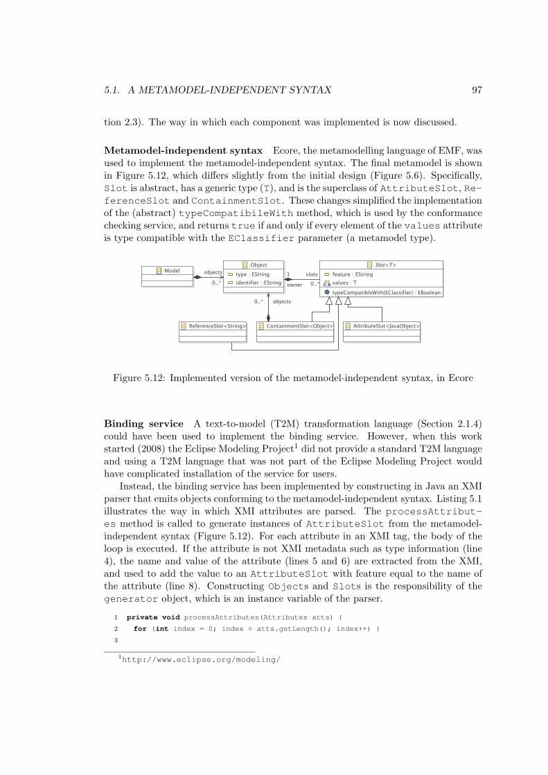
5.1. A METAMODEL-INDEPENDENT SYNTAX 97
tion 2.3). The way in which each component was implemented is now discussed.
Metamodel-independent syntax Ecore, the metamodelling language of EMF, wasused to implement the metamodel-independent syntax. The final metamodel is shownin Figure 5.12, which differs slightly from the initial design (Figure 5.6). Specifically,Slot is abstract, has a generic type (T), and is the superclass of AttributeSlot, Re-ferenceSlot and ContainmentSlot. These changes simplified the implementationof the (abstract) typeCompatibileWith method, which is used by the conformancechecking service, and returns true if and only if every element of the values attributeis type compatible with the EClassifier parameter (a metamodel type).
Figure 5.12: Implemented version of the metamodel-independent syntax, in Ecore
Binding service A text-to-model (T2M) transformation language (Section 2.1.4)could have been used to implement the binding service. However, when this workstarted (2008) the Eclipse Modeling Project1 did not provide a standard T2M languageand using a T2M language that was not part of the Eclipse Modeling Project wouldhave complicated installation of the service for users.
Instead, the binding service has been implemented by constructing in Java an XMIparser that emits objects conforming to the metamodel-independent syntax. Listing 5.1illustrates the way in which XMI attributes are parsed. The processAttribut-es method is called to generate instances of AttributeSlot from the metamodel-independent syntax (Figure 5.12). For each attribute in an XMI tag, the body of theloop is executed. If the attribute is not XMI metadata such as type information (line4), the name and value of the attribute (lines 5 and 6) are extracted from the XMI,and used to add the value to an AttributeSlot with feature equal to the name ofthe attribute (line 8). Constructing Objects and Slots is the responsibility of thegenerator object, which is an instance variable of the parser.
1 private void processAttributes(Attributes atts) {
2 for (int index = 0; index < atts.getLength(); index++) {
3
1http://www.eclipse.org/modeling/

98 CHAPTER 5. DESIGN AND IMPLEMENTATION
1 context Object {
2 constraint ClassMustNotBeAbstract {
3 check: not self.toClass().isAbstract()
4 message: ’Cannot instantiate the abstract class: ’ + self.type
5 }
6 }
7
8 operation Object toClass() : EClass {
9 return Metamodel!EClass.all.selectOne(c|c.name == self.type);
10 }
Listing 5.2: A constraint (in EVL) to check that only concrete metamodel types are
instantiated
4 if (!attributeIsMetadata(atts.getQName(index))) {
5 final String feature = atts.getLocalName(index);
6 final String value = atts.getValue(index);
7
8 generator.addAttributeValue(feature, value);
9 }
10 }
11 }
Listing 5.1: Parsing XMI attributes (in Java)
Conformance checking service EVL (Section 2.1.4), a language tailored for modelverification and hence suitable for rapid prototyping of consistency constraints, wasused to implement the conformance constraints (Figure 5.11). Listing 5.2 shows theEVL constraint that checks whether each Object’s type is a non-abstract class (con-straint 1 in Figure 5.11). The check part (line 3) verifies that a particular Object(referenced via the self keyword) refers to a metamodel type that is not abstract.If the check fails, the message (line 4) is automatically added to a set of unsatisfiedconstraints. The toClass operation (lines 8-10) is used to determine the metamodelclass (an instance of EClass) to which the type attribute (a String) of an Objectrefers. The conformance checking service returns a report of unsatisfied constraints.
Type-compatibility checks have been implemented using the type-checking methodsprovided by EMF. The EVL constraints call the isTypeCompatibleWith methodon the Slot class. Each subclass of Slot provides an implementation of isTypeCo-mpatibleWith, which delegates to EMF to perform type-checking.
5.1.5 Applications of the Metamodel-Independent Syntax
There are many potential uses for the metamodel-independent syntax described inthis section. Section 5.2 describes a textual modelling notation integrated with the

5.1. A METAMODEL-INDEPENDENT SYNTAX 99
metamodel-independent syntax to achieve live conformance checking. In addition tothis, the metamodel-independent syntax is potentially useful during metamodel instal-lation. As discussed in Section 4.2.1, metamodel developers do not have access todownstream models, and conformance is implicitly enforced by modelling frameworks.Consequently, the conformance of models may be affected by the installation of a newversion of a metamodel, and the conformance of models cannot be checked during in-stallation. Typically, installing a new version of a metamodel can result in models thatno longer conform to their metamodel and cannot be used with the modelling frame-work. Moreover, a user discovers conformance problems only when attempting to usea model after installation has completed, and not as part of the installation process.
To enable conformance checking during metamodel installation in EMF, the meta-model-independent syntax has been integrated with a model indexing service, Concor-dance [Rose et al. 2010c]. The work was conducted outside of the scope of the thesis,and is now summarised to indicate the usefulness of the metamodel-independent syn-tax for supporting the automation of co-evolution activities. Concordance provides amechanism for resolving inter-model references (such as those between models and theirmetamodels). Without Concordance, determining the the instances of a metamodel ispossible only by checking every model in the workspace. Integrating Concordance andthe metamodel-independent syntax resulted in a service, which Epsilon (Section 2.3.2)executes after the installation of a metamodel, to identify the models that are affectedby the metamodel changes. All models that conform to the old version of the meta-model are checked for conformance with the new metamodel. As such, conformancechecking occurs automatically and immediately after metamodel installation. Confor-mance problems are detected and reported immediately, rather than when an affectedmodel is next used. Conformance problems detected via Concordance can be reconciledwith the structures described in Sections 5.2 and 5.4.
Summary
Modelling frameworks implicitly enforce conformance, which presents challenges formanaging co-evolution. In particular, detecting and reconciling conformance problemsinvolves managing non-conformant models, which cannot be loaded by modelling frame-works and hence cannot be used with model editors or model management operations.The metamodel-independent syntax proposed in this section enables modelling frame-works to load non-conformant models, and has has been integrated with Concordance[Rose et al. 2010c] to facilitate the reporting of conformance problems during meta-model installation. The metamodel-independent syntax, binding service and confor-mance checking service underpin the implementation of the textual modelling notationpresented in the sequel. The benefits and drawbacks of the metamodel-independentsyntax in the context of user-driven co-evolution are explored in Chapter 6.
100 CHAPTER 5. DESIGN AND IMPLEMENTATION
5.2 Epsilon HUTN: A Textual Modelling Notation
The analysis of co-evolution examples in Chapter 4 highlighted two ways in whichco-evolution is managed. In developer-driven co-evolution, migration is specified bythe metamodel developer in an executable format; while in user-driven co-evolutionmigration is specified by the metamodel developer in prose or not at all. Performinguser-driven co-evolution with modelling frameworks presents two key challenges thathave not been explored by existing research. Firstly, user-driven co-evolution ofteninvolves editing the storage representation of the model, such as XMI. Model stor-age representations are typically not optimised for human use and hence user-drivenco-evolution can be error-prone. Secondly, non-conformant model elements must beidentified during user-driven co-evolution. When a multi-pass parser is used to loadmodels, as is the case with EMF, not all conformance problems are reported at once,and user-driven co-evolution is an iterative process. In Section 4.3, these challenges ledto the identification of the following requirement: This thesis must demonstrate a user-driven co-evolution process that enables the editing of non-conformant models withoutdirectly manipulating the underlying storage representation and provides a sound andcomplete conformance report for the original model and evolved metamodel.
Section 5.2.1 illustrates some of the challenges to performing model migration withXMI, and Section 5.2.2 discusses potential alternatives to XMI for user-driven co-evolution. Section 5.2.3 describes an OMG standard modelling notation that is opti-mised for human-usability, and Section 5.2.4 presents a reference implementation of theOMG standard that is interoperable with EMF. Finally, Section 5.2.5 demonstrates theway in which the reference implementation of the notation has been integrated withthe metamodel independent syntax described in Section 5.1 to produce conformancereports. The work presented in this section has been published in [Rose et al. 2008a].
5.2.1 Model Migration with XMI
The co-evolution example from Section 5.1 is re-used in this section to illustrate the wayin which model migration is performed by editing the underlying storage representationof a model, such as XMI (Section 2.1.3). For convenience, Figures 5.3 and 5.4 arerepeated here as Figures 5.13 and 5.14, respectively. Recall that the model (Figure 5.14)conforms to the original metamodel (Figure 5.13(a)).
The model in Figure 5.14 does not conform to the evolved metamodel (because ituses the naturalChildren and adoptedChildren features, which are not definedfor Person), and hence cannot be loaded by the modelling framework. Migration mightbe achieved by editing the underlying storage representation directly (i.e. manuallymanipulating XMI). Listing 5.3 shows the XMI for the model in Figure 5.14.
1 <?xml version="1.0" encoding="ASCII"?>
2 <families:Family xmi:version="2.0" xmlns:xmi="http://www.omg.org/XMI"
xmlns:families="families" xmi:id="_kE2LkAagEeC-FIOYrvUj0A" name="Smiths">
3 <naturalChildren xmi:id="_q8RWYAagEeC-FIOYrvUj0A" name="Paul"/>
4 <adoptedChildren xmi:id="_nj6TcAagEeC-FIOYrvUj0A" name="John"/>

5.2. EPSILON HUTN: A TEXTUAL MODELLING NOTATION 101
(a) Original metamodel.
(b) Evolved metamodel.
Figure 5.13: Reproduction of Figure 5.3: Evolution of a families metamodel, based onthe metamodel in [OMG 2004].
Figure 5.14: Reproduction of Figure 5.4: A family model, which conforms to themetamodel in Figure 5.13(a)

102 CHAPTER 5. DESIGN AND IMPLEMENTATION
5 </families:Family>
Listing 5.3: XMI for the family model in Figure 5.14
XMI is a concrete syntax for models, which has been optimised for use by machinesand not by humans [OMG 2004]. Models often contain information that is not relevantto the domain, such as the universally unique identifiers (xmi:id attributes) on lines2, 3 and 4 of Listing 5.3. Furthermore, information is often omitted to reduce the sizeof the model on disk. For example, the model elements on lines 3 and 4 of Listing 5.3 donot specify their type (Person) and this is inferred from the type of the naturalCh-ildren and adoptedChildren features. Types are inferred from the metamodel bythe modelling framework using a reference from the model to the metamodel. In XMI,metamodel references are expressed using XML namespaces. The XMI in Listing 5.3imports the families metamodel to a namespace (families) on line 2. The evaluationpresented in Section 6.1 further explores the suitability of XMI for user-driven co-evolution. The remainder of this section discusses the design and implementation of amodelling notation that provides an alternative to XMI, and is tailored for human-use.
5.2.2 Potential Alternatives to XMI
Two characteristics were considered when designing a notation that provides an al-ternative to representing models with XMI. Models can be represented textually orgraphically (Section 2.1.2), and with a metamodel-specific or a metamodel-independentsyntax (Section 5.1). The benefits and drawbacks of each option have been consideredparticularly with respect to their implications for user-driven co-evolution, and are nowdiscussed.
Metamodel-independent vs metamodel-specific A metamodel-specific syntax isdefined using terms from the metamodel, and is often more concise than a metamodel-independent syntax. A metamodel-specific (and textual) syntax for part of the originalfamilies metamodel (Figure 5.13(a)) is shown in Listing 5.4. Using the metamodel-specific syntax, the families model in Listing 5.3 is written Smiths:Paul(John).Notice that the syntax is defined in metamodel terms, such as Family, naturalCh-ildren, and adoptedChildren. Consequently, the syntax definition can be affectedby metamodel evolution, and hence cannot be used to load a model that does not con-form to the metamodel. Therefore, a metamodel-specific representation is not suitablefor use during user-driven co-evolution, which involves using a modelling notation withnon-conformant models. Here, a metamodel-independent representation is preferred.
1 family = name ":" naturalChildren "(" adoptedChildren ")"
2 naturalChildren = name { "," naturalChildren }
3 adoptedChildren = name { "," adoptedChildren }
4 name = "A" | ... | "z"
Listing 5.4: A metamodel-specific syntax for families in EBNF
5.2. EPSILON HUTN: A TEXTUAL MODELLING NOTATION 103
Textual vs graphical For user-driven co-evolution, the usability of the modellingnotation is important because a metamodel user manipulates models with the notationto perform migration. The choice between a textual or graphical notation is likely tohave a significant impact on usability, but it was not feasible to conduct a thoroughuser analysis given the time constraints of the thesis. Instead, a textual notation wasselected to reduce implementation effort, and implemented to facilitate the additionof an equivalent graphical notation in future work. In particular, the concrete andabstract syntax definitions of the notation were kept separate to simplify future additionof alternative concrete syntax, such as a graphical notation.
Currently, several tools exist for representing models with textual and metamodel-specific syntaxes (such as the text-to-model transformation tools discussed in Sec-tion 2.1.4), but only XMI represents models in a metamodel-independent syntax.The Distributed Systems Technology Centre’s TokTok project provided a metamo-del-independent textual modelling notation [Steel & Raymond 2001], but the tool hasbeen abandoned and the source code has vanished. Sintaks2, a tool for constructingmetamodel-specific representations, was originally intended to provide a metamodel-independent representation [Muller & Hassenforder 2005].
The TokTok project and earlier versions of Sintaks based their metamodel-indepen-dent representations on an OMG standard, Human-Usable Textual Notation (HUTN)[Steel & Raymond 2001, Muller & Hassenforder 2005]. HUTN defines a textual mod-elling notation that aims to conform to human-usability criteria [OMG 2004]. As a me-tamodel-independent and textual concrete syntax, HUTN was seen as an ideal startingpoint for designing a textual modelling notation for user-driven co-evolution. OMGHUTN is described in the sequel.
5.2.3 OMG Human-Usable Textual Notation
OMG HUTN is a textual, metamodel-independent modelling notation whose primarydesign goal is human-usability and “this is achieved through consideration of the suc-cesses and failures of common programming languages” [OMG 2004, Section 2.2]. TheHUTN specification refers to two studies of programming language usability to justifydesign decisions. However, the OMG specification cannot evaluate the human-usabilityof the notation because no reference implementation exists. As HUTN is (purport-edly) optimised for human-usability, using HUTN rather than XMI for user-drivenco-evolution should lead to increased developer productivity. This claim is explored inChapter 6.
Like the metamodel presented in Section 5.1, HUTN provides a metamodel-indep-endent syntax for MOF. However, the OMG HUTN specification focuses on concretesyntax, whereas the metamodel-independent syntax presented in Section 5.1 focuseson abstract syntax. In this section, the key features of HUTN are introduced, and thesequel describes a reference implementation of HUTN. Throughout the remainder ofthis section, the original families metamodel (Figure 5.3(a), 5.13(a)) is used to illustrate
2http://www.kermeta.org/sintaks/

104 CHAPTER 5. DESIGN AND IMPLEMENTATION
the notation.
Basic Notation
Listing 5.5 shows the construction of an object (an instance of a metamodel class) inOMG HUTN, here an instance of the Family class from Figure 5.13(a). Line 1 specifiesthe metamodel package containing the metamodel classes that can be instantiated bythis model (FamilyPackage). A package declaration in OMG HUTN is equivalentto a namespace import at the start of an XMI document (e.g. line 2 of Listing 5.3).In Listing 5.5, line 2 names the metamodel class to be instantiated (Family) andgives an identifier for the object (The Smiths). Package and object identifiers areoptional in OMG HUTN, have no direct equivalent in XMI, and are used to specifyreference values (discussed below). Lines 3 to 7 define attribute values; in each case,the data value is assigned to the attribute with the specified name. The encoding ofthe value depends on its type: strings are delimited by any form of quotation mark;multi-valued attributes use comma separators, etc. HUTN accesses type informationfrom the metamodel (Figure 5.13(a) here), which the user references in the packagedeclaration (on line 1).
The metamodel in Figure 5.13(a) has a simple reference (familyFriends) andtwo containment references (adoptedChildren; naturalChildren). The OMGHUTN representation embeds a contained object directly in the parent object, as shownin Listing 5.6. A simple reference can be specified using the type and identifier of thereferred object, as shown in Listing 5.7. Like attribute values, both styles of referenceare preceded by the name of the meta-feature.
1 FamilyPackage "families" {
2 Family "The Smiths" {
3 nuclear: true
4 name: "The Smiths"
5 averageAge: 25.7
6 numberOfPets: 2
7 address: "120 Main Street", "37 University Road"
8 }
9 }
Listing 5.5: Specifying attributes with HUTN, taken from [Rose et al. 2008a]
1 FamilyPackage "families" {
2 Family "The Smiths" {
3 naturalChildren: Person "John" { name: "John" },
4 Person "Jo" { gender: female }
5 }
6 }
Listing 5.6: Specifying a containment reference with HUTN, taken from
[Rose et al. 2008a]

5.2. EPSILON HUTN: A TEXTUAL MODELLING NOTATION 105
1 FamilyPackage "families" {
2 Family "The Smiths" {
3 familyFriends: Family "The Does"
4 }
5 Family "The Does" {}
6 }
Listing 5.7: Specifying a simple reference with HUTN, taken from [Rose et al. 2008a]
Keywords and Adjectives
In general, a metamodel-independent syntax (such as OMG HUTN) is more verbosethan a metamodel-specific concrete syntax. However, OMG HUTN defines optionalsyntactic shortcuts to make model specifications more concise, and aims to make thesyntactic shortcuts intuitive [OMG 2004, pg2-4].
Two of the syntactic shortcuts relate to Boolean-valued attributes and are nowdiscussed; a complete list of syntactic shortcuts is provided in the OMG HUTN specifi-cation [OMG 2004]. OMG HUTN permits the use of an attribute name to represent thevalue true, or the attribute name prefixed with a tilde to represent the value false).When used in the body of the object, this style of Boolean-valued attribute represents akeyword. A keyword used to prefix an object declaration is called an adjective. Listing5.8 shows the use of both an attribute keyword (˜nuclear on line 6) and adjective(migrant on line 2), and states that The Smiths are migrant and that The Doesare not nuclear.
1 FamilyPackage "families" {
2 migrant Family "The Smiths" {}
3
4 Family "The Does" {
5 averageAge: 20.1
6 ˜nuclear
7 name: "The Does"
8 }
9 }
Listing 5.8: Keywords and adjectives in HUTN, taken from [Rose et al. 2008a]
Alternative Reference Syntax
In addition to the syntax defined in Listings 5.6 and 5.7, OMG HUTN defines twoalternative syntactic constructs for specifying the value of references. For example,Listing 5.9 demonstrates the use of a reference block for defining The Does as friendswith both The Smiths and The Bloggs. Listing 5.10 illustrates a further alternativesyntax for references, which employs an infix notation.
1 FamilyPackage "families" {
2 Family "The Smiths" {}

106 CHAPTER 5. DESIGN AND IMPLEMENTATION
3 Family "The Does" {}
4 Family "The Bloggs" {}
5
6 familyFriends {
7 "The Does" "The Smiths"
8 "The Does" "The Bloggs"
9 }
10 }
Listing 5.9: A reference block in HUTN, taken from [Rose et al. 2008a]
1 FamilyPackage "families" {
2 Family "The Smiths" {}
3 Family "The Does" {}
4 Family "The Bloggs" {}
5
6 Family "The Smiths" familyFriends Family "The Does";
7 Family "The Smiths" familyFriends Family "The Bloggs";
8 }
Listing 5.10: An infix reference in HUTN, taken from [Rose et al. 2008a]
The reference block (Listing 5.9) and infix (Listing 5.10) notations are syntacticvariations on – and have identical semantics to – the reference notation shown inListings 5.6 and 5.7.
Customisation via Configuration
The OMG HUTN specification allows some limited, metamodel-specific customisationof the notation, using configuration rules. Customisations include a parametric formof object instantiation; renaming of metamodel elements; specifying the default valueof a feature; and providing a default identifier for classes of object.
5.2.4 Reference Implementation: Epsilon HUTN
To investigate the extent to which OMG HUTN can be used for user-driven co-evolution, a reference implementation, Epsilon HUTN, has been designed and imple-mented. This section describes the way in which Epsilon HUTN was implemented usinga combination of model-management operations. From text conforming to the OMGHUTN syntax (described above), Epsilon HUTN produces an equivalent model thatcan be managed with EMF (Section 2.3.1). The sequel demonstrates the way in whichEpsilon HUTN can be used for user-driven co-evolution.
Design of Epsilon HUTN
Implementing OMG HUTN involved building a tool for producing an EMF model (i.e. amodel represented in XMI) from text conforming to the OMG HUTN syntax (described

5.2. EPSILON HUTN: A TEXTUAL MODELLING NOTATION 107
above). Essentially then, Epsilon HUTN can be regarded as a parser (that emits mod-els), or as a text-to-model transformation. Several approaches to constructing EpsilonHUTN were considered, including: using a text-to-model (T2M) transformation tool(Section 2.1.4), using a domain-specific language (DSL) framework (Section 2.4.1), andusing MDE tools and techniques such as EMF (Section 2.3.1), Epsilon (Section 2.3.2)and metamodelling.
As was the case for the design and implementation of the metamodel-independentsyntax (Section 5.1), it was preferrable to avoid dependencies on tools that were not partof the Eclipse Modelling Project (in order not to complicate installation of the notationfor users). In 2008, the Eclipse Modeling Project3 did not provide a standard T2Mlanguage or DSL framework, and so these implementation strategies were discounted.
Instead, Epsilon HUTN was constructed using existing languages of the Epsilonplatform. To parse HUTN source, a parser was generated with the ANTLR parsergenerator tool [Parr 2007], which had been used successfully to implement parsersfor every task-specific language of Epsilon [Kolovos 2009]. A parser generated withANTLR emits an abstract syntax tree (a set of Java objects that conform to a simpletree data structure), from which the Epsilon HUTN tool needs to produce an EMFmodel.
Figure 5.15: A metamodel for abstract syntax trees, in Ecore
The abstract syntax tree produced by ANTLR can be regarded as a model (con-forming to the metamodel in Figure 5.15) and hence, producing an EMF model fromthe abstract syntax tree can be regarded as a model-to-model transformation. Ep-silon HUTN, however, was designed as two separate model-to-model transformations,for two reasons. Firstly, initial prototyping highlighted that the difference between amodel represented in terms of the tree metamodel in Figure 5.15 and the same modelrepresented in metamodel-specific terms is vast, and the logic required to perform aone-step transformation quickly became complicated even for simple models. In par-ticular, each transformation rule would have required a lengthly guard statement todistinguish Nodes representing different types of model element, which would havebeen difficult to debug and maintain. Secondly, it became apparent that the concretesyntax defined in OMG HUTN could be transformed to the metamodel-independent
3http://www.eclipse.org/modeling/

108 CHAPTER 5. DESIGN AND IMPLEMENTATION
syntax defined in Section 5.1, which would reduce implementation effort by re-usingthe metamodel and conformance checking service described in Section 5.1.
Implementation of Epsilon HUTN
For the reasons outlined above, Epsilon HUTN is implemented using two model-to-model transformations. Figure 5.16 outlines the workflow through Epsilon HUTN,from HUTN source text to an EMF instantiation of the target model. The HUTNmodel specification is parsed to an abstract syntax tree using a HUTN parser speci-fied in ANTLR [Parr 2007]. From this, a Java postprocessor is used to construct aninstance of the simple AST metamodel in Figure 5.15. Using ETL, a M2M trans-formation is applied to produce an intermediate model, which is an instance of themetamodel-independent syntax discussed in Section 5.1. Validation is performed onthe intermediate model to ensure that the syntactic constraints specified in the OMGHUTN specification are satisfied4, and that the model conforms to the target meta-model. Conformance checking is achieved by re-using the service presented in Sec-tion 5.1. Finally, a M2T transformation on the target metamodel, specified in EGL,produces a further M2M transformation, which consumes the intermediate model andproduces the target model5.
Figure 5.16: The architecture of Epsilon HUTN.
The modular architecture in Figure 5.16 facilitated the re-use of the metamo-del-independent syntax and conformance checking service described in Section 5.1,and hence reduced implementation effort. A small modification was made to themetamodel-independent syntax to facilitate the implementation of Epsilon HUTN: anadditional metaclass, PackageObject, was added to the metamodel-independent syn-tax. In OMG HUTN, packages are used to segregate a model such that different parts ofa OMG HUTN document can refer to different metamodels. Consequently, a Packa-geObject has a type (i.e. the metamodel to which its contents refer), an optional iden-tifier (used for inter-package references) and contains any number of Objects. To avoidconfusion with PackageObject, the Object class in the metamodel-independent
4For example, no two objects may have the same identifier.5This final step involves a higher-order transformation (a M2T transformation is used to produce
a M2M transformation), and is described in more detail below.

5.2. EPSILON HUTN: A TEXTUAL MODELLING NOTATION 109
syntax was renamed to ClassObject. The version of the metamodel-independentsyntax used with Epsilon HUTN is shown in Figure 5.17.
Figure 5.17: Final version of the metamodel-independent syntax, in Ecore
Each module of the architecture in Figure 5.16 is now discussed in detail. Notethat, in this section, instances of the metamodel-independent syntax produced duringthe execution of the HUTN workflow are termed an intermediate model.
Parsing the HUTN Source A parser for OMG HUTN was constructed usingANTLR [Parr 2007], a parser generator tool. ANTLR produces a parser from anannotated EBNF grammar definition. To simplify the implementation of the modeltransformations described below, the EBNF grammar used by Epsilon HUTN variesslightly from the grammar defined in OMG HUTN. Part of the grammar definition usedby Epsilon HUTN is shown in Listing 5.11 and is used to generate parser rules thatprocess the body of ClassObjects. The attr rule on line 4, for example, matchesany number of comma separated attribute values or the null keyword.
Epsilon HUTN uses a simple, bespoke Java post-processor to construct instancesof the abstract syntax tree metamodel (Figure 5.15) from the Java objects producedby ANTLR. Specifically, the post-processor copies the Java objects produced by theparser into an EMF resource, and hence produces a model that can be managed withEMF.
1 cls_contents = feature | adjective
2 feature = NAME ASSIGNMENT feature_contents
3 feature_contents = attr | refs | containments
4 attr = attr_value { COMMA attr } | NULL
Listing 5.11: An extract of the Epsilon HUTN grammar definition in EBNF
AST Model to Intermediate Model For M2M transformation, Epsilon HUTNuses ETL [Kolovos et al. 2008b]. One of the transformation rules from Epsilon HUTNis shown in Listing 5.12; the complete transformation is presented in Listing A.3. In

110 CHAPTER 5. DESIGN AND IMPLEMENTATION
Listing 5.12, the rule (starting on line 1) transforms a Node with type name (whichcould represent a PackageObject or a ClassObject) to a PackageObject inthe intermediate model. The guard (line 5) specifies that a name node will only betransformed to a PackageObject if the node has no parent (i.e. it is a top-levelnode, and hence a package rather than a class). The body of the rule states that thetype, line number and column number of the package are determined from the text,line and column attributes of the Node object. On line 11, the children of the Nodeobject are transformed to the intermediate model (using a method built into ETL,equivalent()), and added to the objects reference of the PackageObject.
1 rule NameNode2PackageObject
2 transform n : AntlrAst!Node
3 to p : Intermediate!PackageObject {
4
5 guard : n.type == ’Name’ and n.parent.isUndefined()
6
7 p.type := n.text;
8 p.line := n.line;
9 p.col := n.column;
10
11 p.objects.addAll(n.children.equivalent());
12 }
Listing 5.12: Transforming Nodes to PackageObjects with ETL.
Intermediate Model Validation An advantage of the two-stage transformationis that contextual analysis can be specified in an abstract manner – that is, withouthaving to express the traversal of the AST. This gives clarity and minimises the amountof code required to define syntactic constraints.
1 context ClassObject {
2 constraint IdentifiersMustBeUnique {
3 guard: self.id.isDefined()
4 check: ClassObject.all
5 .select(c|c.id = self.id).size() = 1;
6 message: ‘Duplicate identifier: ’ + self.id
7 }
8 }
Listing 5.13: A constraint (in EVL) to check that all identifiers are unique
Epsilon HUTN uses EVL [Kolovos et al. 2009] to specify validation, resulting inhighly expressive syntactic constraints. An EVL constraint comprises a guard, thelogic that specifies the constraint, and a message to be displayed if the constraint is notmet. For example, Listing 5.13 specifies the constraint that every HUTN class objecthas a unique identifier. The complete set of constraints is presented in Listing A.4.

5.2. EPSILON HUTN: A TEXTUAL MODELLING NOTATION 111
In addition to the syntactic constraints defined in the OMG HUTN specification,the EVL constraints for checking conformance (Section 5.1) are executed on the modelat this stage.
Intermediate Model to Target Model When the intermediate model conformsto the target metamodel, the intermediate model can be transformed to an instance ofthe target metamodel. In other words, the model can be represented in a metamodel-specific manner and, for example, used with model management operations. In gen-erating the target model from the intermediate model (Figure 5.16), the transforma-tion uses information from the target metamodel, such as the names of classes andfeatures. A typical approach to this category of problem is to use a higher-ordertransformation (HOT) on the target metamodel to generate the desired transforma-tion [Tisi et al. 2009]. Currently, ETL cannot be used to produce a transformationfrom a transformation and hence Epsilon HUTN uses a slightly different approach: thetransformation to the target model is produced by executing a M2T transformation onthe target metamodel, using EGL [Rose et al. 2008b]. EGL is a template-based M2Tlanguage; [% %] tag pairs are used to denote dynamic sections, which may producetext when executed; any code not enclosed in a [% %] tag pair is included verbatimin the generated text.
Listing 5.14 shows part of the M2T transformation used by Epsilon HUTN; thecomplete M2T transformation is presented in Listing A.5. When executed on thetarget metamodel, the M2T transformation generates an ETL program (i.e. a M2Mtransformation). The generated ETL code transforms an intermediate model to a modelthat conforms to the target metamodel. The loop beginning on line 1 of Listing 5.14iterates over each metaclass in the target metamodel, producing a M2M transformationrule. The generated transformation rule consumes a ClassObject in the intermediatemodel and produces an element of the target model. The guard of the generatedtransformation rule (line 6) ensures that only ClassObject with a type equal to thecurrent meta-class are transformed by the generated rule. To generate the body of therule, the M2T transformation iterates over each structural feature of the current meta-class, and generates appropriate transformation code for populating the values of eachstructural feature from the slots on the class object in the intermediate model. Thepart of the M2T transformation that generates the body of the M2M transformationrule is omitted in Listing 5.14 because it contains a large amount of code for interactingwith EMF, which is not relevant to this discussion. The complete M2T transformationis presented in Listing A.5.
1 [% for (class in EClass.allInstances()) { %]
2 rule Object2[%=class.name%]
3 transform o : Intermediate!ClassObject
4 to t : Model![%=class.name%] {
5
6 guard: o.type = ‘[%=class.name%]’
7
8 -- body omitted

112 CHAPTER 5. DESIGN AND IMPLEMENTATION
9 }
10 [% } %]
Listing 5.14: Part of the M2T transformation (in EGL) that takes a target metamodel
and generates an intermediate model to target model transformation (in ETL).
To illustrate the way in which Epsilon HUTN generates a target model from anintermediate model, the M2T transformation in Listing 5.14 is applied to the the fam-ilies metamodel in Figure 5.13(a). The M2T transformation generates the two M2Mtransformation rules in Listing 5.15. The rules produce instances of Family and Pe-rson from instances of ClassObject in the intermediate model. The body of eachrule copies the values from the slots of the ClassObject to the Family or Personin the target model. Lines 7-9, for example, copy the value of the name Slot (if oneis specified) to the target Family.
Currently, Epsilon HUTN can be used only to generate EMF models. Support forother modelling languages would require different transformations between intermedi-ate and target model. In other words, for each target modelling language, a new EGLtemplate would be required. The transformation from AST to intermediate model isindependent of the target modelling language and would not need to change. As EMFis arguably the most widely-used modelling framework today, support for other mod-elling frameworks is not crucial for exploring the suitability of HUTN for user-drivenco-evolution. However, one interesting example of metamodel evolution predates EMF:the changes made to UML between versions 1.5 and 2.0 of the specification. Becausethe UML 1.x specifications use a version of MOF that is not supported by EMF, thecurrent version of Epsilon HUTN cannot be used for migrating UML 1.x models. Sev-eral other examples, however, were available for evaluating Epsilon HUTN, and sosupport for other modelling frameworks was not crucial in the context of the thesisresearch.
Compliance with OMG HUTN
Epsilon HUTN is a reference implementation of the OMG HUTN standard. Thereare, however, a few differences between the implementation in Epsilon and the OMGstandard. The differences are now discussed and justified. The discussion is basedon the Epsilon HUTN compliance report6, which provides up-to-date information oncompliance with the OMG HUTN standard.
Table 5.2 summarises the differences between Epsilon HUTN and the OMG HUTNstandard. Epsilon HUTN does not support two of the syntactic shortcuts described forclasses in the OMG HUTN standard: parametric attributes and enumeration adjectives.The former are used to specify attribute values in a parametric form (e.g. Point(0,0), for creating a Point object with x and y attributes with value 0). The latterallows an enumeration value to prefix an object definition (e.g. female Person forcreating a Person with female gender). The attribute to which the parametric
6http://www.eclipse.org/gmt/epsilon/doc/articles/hutn-compliance/

5.2. EPSILON HUTN: A TEXTUAL MODELLING NOTATION 113
1 rule Object2Family
2 transform o : Intermediate!ClassObject
3 to t : Model!Family {
4
5 guard: o.type = ’Family’
6
7 if (o.hasSlot(’name’)) {
8 t.name := o.findSlot(’name’).values.first;
9 }
10
11 if (o.hasSlot(’address’)) {
12 for (value in o.findSlot(’address’).values) {
13 t.address.add(value);
14 }
15 }
16
17 -- remainder of body omitted
18 }
19
20 rule Object2Person
21 transform o : Intermediate!ClassObject
22 to t : Model!Person {
23
24 guard: o.type = ’Person’
25
26 if (o.hasSlot(’name’)) {
27 t.name := o.findSlot(’name’).values.first;
28 }
29
30 -- remainder of body omitted
31 }
Listing 5.15: The M2M transformation generated for the Families metamodel
or enumeration values are bound is specified using OMG HUTN configuration rules(Section 5.2.3). Parametric attribute and enumeration adjectives were not implementedto reduce the amount of time required to build Epsilon HUTN, but could be easily addedin the future. No functionality is lost through these omissions, as alternative (albeitless concise) notion can be used to express models without using parametric attributeand enumeration adjectives.
Section 6.4 of the OMG HUTN standard [OMG 2004] appears to contain a mistakein the grammar definition. Grammar rule 20 implies that an attribute’s name is optionalwhen specifying a keyword attribute, and that an empty string and a tilde characterare valid forms of a keyword attribute. However, the prose describing grammar rule 20proposes no semantics for an empty string or a tilde character as a keyword attribute.

114 CHAPTER 5. DESIGN AND IMPLEMENTATION
OMG HUTN Epsilon HUTNFeature Supported? Details of support
Packages Yes
Classes PartialNot yet supported:
parametric attributes,enumeration adjectives.
Attributes YesCorrects a mistake
in the standard.References Yes
Classifier-level attributes YesData values Yes
Inline configuration NoA configuration model
is used instead.
Configuration rules PartialNot yet supported:
parametric attributes,enumeration adjectives.
Table 5.2: Compliance of Epsilon HUTN with OMG HUTN
Consequently, Epsilon HUTN deviates from grammar rule 20 of the OMG HUTNstandard, and requires an attribute name for every keyword attribute.
Finally, the OMG HUTN standard defines syntax for specifying configuration rulesinline, at the start of a HUTN document. Epsilon HUTN does not support inline con-figuration, and Epsilon HUTN documents are configured with a configuration model,which is constructed using an EMF model editor. Using a configuration model ratherthan inline configuration reduced the time required to implement Epsilon HUTN andfacilitated re-use of configuration models between HUTN documents.
The OMG HUTN standard does not include a set of compliance tests for refer-ence implementations. Instead, the compliance of Epsilon HUTN to OMG HUTN waschecked using the many examples of HUTN documents in the OMG HUTN standard[OMG 2004]. The examples were used to create a suite of executable compliance testcases, which were run frequently during the development of Epsilon HUTN.
5.2.5 Migration with Epsilon HUTN
Used in combination with the metamodel-independent syntax presented in Section 5.1,Epsilon HUTN facilitates user-driven co-evolution using the workflow in Section 5.18,which provides an alternative to the user-driven co-evolution workflow observed in Sec-tion 4.2.2. First, the user attempts to load a model with the model editor7. If the modelis non-conformant and cannot be loaded, the user clicks a “Generate HUTN” menu itemprovided by Epsilon HUTN. Epsilon HUTN then binds the model to the metamodel-
7The workflow in Figure 5.18 assumes a graphical model editor, such as those generated by GMF,but any editor built with EMF will exhibit the same behaviour.

5.2. EPSILON HUTN: A TEXTUAL MODELLING NOTATION 115
1 FamilyPackage "families" {
2 Family "Smiths" {
3 name: "Smiths"
4 naturalChildren: Person { name: "Paul" }
5 adoptedChildren: Person { name: "John" }
6 }
7 }
Listing 5.16: OMG HUTN for people with mothers and fathers.
independent syntax and unparses the bound model to produce HUTN source codeequivalent to XMI representation of the non-conformant model.
To support the final step of the workflow in Figure 5.18, Epsilon HUTN provides aneditor for HUTN documents that is integrated with the conformance checking service(described in Section 5.1). The user edits the HUTN document to reconcile confor-mance problems (i.e. performs migration), and Epsilon HUTN automatically performsconformance checking as the user edits the HUTN document. When the conformanceproblems are fixed, the user saves the HUTN document and Epsilon HUTN auto-matically generates XMI for the conformant model (using the model transformationsdescribed in Section 5.2.4). The conformant model can then be loaded with the modeleditor.
Attempt to load model with
graphical editor
Does EMF report any conformance problems?
No
YesInvoke
XMI-to-HUTN transformation
Edit HUTN of non-conformant
model
Figure 5.18: User-driven co-evolution with dedicated structures
To demonstrate the way in which HUTN can be used to perform migration, theXMI shown in Listing 5.3 is represented using OMG HUTN in Listing 5.16. Recallthat the XMI describes a Family with one adopted and one natural child.
If the Families metamodel now evolves such that children are modelled using onerather than two features (Figure 5.13(b)), Epsilon HUTN reports conformance prob-lems on the HUTN document using the conformance checking service described inSection 5.1, as illustrated by the screenshot in Figure 5.19.
Resolving the conformance problems requires the user to merge the values for ad-optedChildren and naturalChildren into a set of values for the new feature,

116 CHAPTER 5. DESIGN AND IMPLEMENTATION
Figure 5.19: Conformance problem reporting in Epsilon HUTN.
1 FamilyPackage "families" {
2 Family "Smiths" {
3 name: "Smiths"
4 children: Person { name: "Paul" },
5 Person { name: "John" }
6 }
7 }
Listing 5.17: HUTN for people with parents.
children. The Epsilon HUTN development tools provide content assistance, whichmight be useful in this situation. Listing 5.17 shows a HUTN document that conformsto the evolved metamodel in which adopted and natural children are specified using asingle feature, children.
When the user saves the reconciled HUTN document, Epsilon HUTN will auto-matically generate XMI for the (now) conformant model, and migration is complete.Compared to the user-driven co-evolution workflow observed in Section 4.2.2, the work-flow presented in Figure 5.18 provides live conformance checking and a modelling no-tation that is optimised for humans rather than for machines. The two workflows arecompared and evaluated in Chapter 6.
5.2.6 Summary
In this section, a textual modelling notation for performing model migration has beendesigned and implemented. The notation proposed in this section is based on the OMGHUTN standard, which was described in Section 5.2.3. The design and implementa-tion of Epsilon HUTN, an implementation of OMG HUTN for EMF, was discussedin this section. Integration of Epsilon HUTN with the metamodel-independent syntaxin Section 5.1 facilitates user-driven co-evolution with a textual modelling notationother than XMI, as demonstrated by the example above. The user-driven co-evolutionworkflow presented in Section 5.2.5 is evaluated in Chapter 6. The remainder of thischapter focuses on developer-driven co-evolution, in which model migration strategiesare executable.

5.3. AN ANALYSIS OF MODEL MIGRATION LANGUAGES 117
5.3 An Analysis of Languages used for Model Migration
In contrast to the previous section, this section focuses on developer-driven co-evolution,in which migration is specified as a program that metamodel users execute to migratetheir models. Section 4.2.3 discussed existing approaches to model migration, highlight-ing variation in the languages used for specifying migration strategies. In this section,the results of comparing migration strategy languages are described, using a new ex-ample of metamodel evolution (Section 5.3.1). From the comparison, requirements fora domain-specific language for specifying and executing model migration strategies arederived (Section 5.3.3). The sequel describes an implementation of a model migrationlanguage based on the analysis presented here. The work described in this section hasbeen published in [Rose et al. 2010f].
5.3.1 Co-Evolution Example
The Petri net metamodel evolution is now used to compare model migration lan-guages. The example has been used often in co-evolution literature, and hence isa useful benchmark for migration languages [Cicchetti et al. 2008, Garces et al. 2009,Wachsmuth 2007].
In Figure 5.20(a), a Petri Net is defined to comprise Places and Transitions.A Place has any number of src or dst Transitions. Similarly, a Transitionhas at least one src and dst Place. The metamodel is to be evolved to supportweighted connections between Places and Transitions and between Transitionsand Places, as shown in Figure 5.20(b). Places are connected to Transitions viainstances of PTArc. Likewise, Transitions are connected to Places via TPArc.Both PTArc and TPArc inherit from Arc, and can be used to specify a weight.
Models that conform to the original metamodel might not conform to the evolvedmetamodel. The following strategy can be used to migrate models:
1. For every instance, t, of Transition:
For every Place, s, referenced by the src feature of t:
Create a new instance, arc, of PTArc.
Set s as the src of arc.
Set t as the dst of arc.
Add arc to the arcs reference of the Net referenced by t.
For every Place, d, referenced by the dst feature of t:
Create a new instance, arc, of TPArc.
Set t as the src of arc.
Set d as the dst of arc.
Add arc to the arcs reference of the Net referenced by t.
2. And nothing else changes.
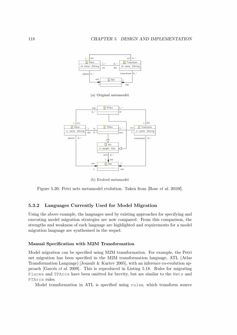
118 CHAPTER 5. DESIGN AND IMPLEMENTATION
(a) Original metamodel.
(b) Evolved metamodel.
Figure 5.20: Petri nets metamodel evolution. Taken from [Rose et al. 2010f].
5.3.2 Languages Currently Used for Model Migration
Using the above example, the languages used by existing approaches for specifying andexecuting model migration strategies are now compared. From this comparison, thestrengths and weakness of each language are highlighted and requirements for a modelmigration language are synthesised in the sequel.
Manual Specification with M2M Transformation
Model migration can be specified using M2M transformation. For example, the Petrinet migration has been specified in the M2M transformation language, ATL (AtlasTransformation Language) [Jouault & Kurtev 2005], with an inference co-evolution ap-proach [Garces et al. 2009]. This is reproduced in Listing 5.18. Rules for migratingPlaces and TPArcs have been omitted for brevity, but are similar to the Nets andPTArcs rules.
Model transformation in ATL is specified using rules, which transform source
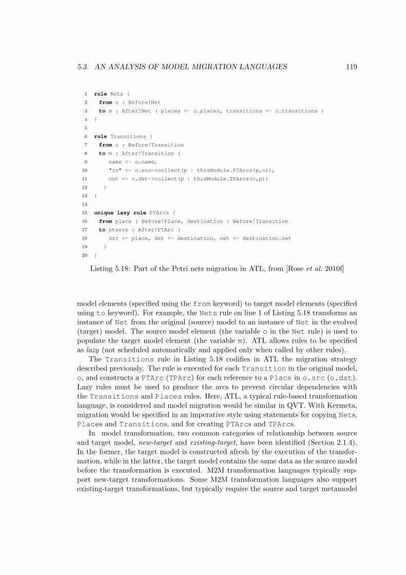
5.3. AN ANALYSIS OF MODEL MIGRATION LANGUAGES 119
1 rule Nets {
2 from o : Before!Net
3 to m : After!Net ( places <- o.places, transitions <- o.transitions )
4 }
5
6 rule Transitions {
7 from o : Before!Transition
8 to m : After!Transition (
9 name <- o.name,
10 "in" <- o.src->collect(p | thisModule.PTArcs(p,o)),
11 out <- o.dst->collect(p | thisModule.TPArcs(o,p))
12 )
13 }
14
15 unique lazy rule PTArcs {
16 from place : Before!Place, destination : Before!Transition
17 to ptarcs : After!PTArc (
18 src <- place, dst <- destination, net <- destination.net
19 )
20 }
Listing 5.18: Part of the Petri nets migration in ATL, from [Rose et al. 2010f]
model elements (specified using the from keyword) to target model elements (specifiedusing to keyword). For example, the Nets rule on line 1 of Listing 5.18 transforms aninstance of Net from the original (source) model to an instance of Net in the evolved(target) model. The source model element (the variable o in the Net rule) is used topopulate the target model element (the variable m). ATL allows rules to be specifiedas lazy (not scheduled automatically and applied only when called by other rules).
The Transitions rule in Listing 5.18 codifies in ATL the migration strategydescribed previously. The rule is executed for each Transition in the original model,o, and constructs a PTArc (TPArc) for each reference to a Place in o.src (o.dst).Lazy rules must be used to produce the arcs to prevent circular dependencies withthe Transitions and Places rules. Here, ATL, a typical rule-based transformationlanguage, is considered and model migration would be similar in QVT. With Kermeta,migration would be specified in an imperative style using statements for copying Nets,Places and Transitions, and for creating PTArcs and TPArcs.
In model transformation, two common categories of relationship between sourceand target model, new-target and existing-target, have been identified (Section 2.1.4).In the former, the target model is constructed afresh by the execution of the transfor-mation, while in the latter, the target model contains the same data as the source modelbefore the transformation is executed. M2M transformation languages typically sup-port new-target transformations. Some M2M transformation languages also supportexisting-target transformations, but typically require the source and target metamodel

120 CHAPTER 5. DESIGN AND IMPLEMENTATION
to be identical.In model migration, source and target metamodels differ, and therefore existing-
target transformations cannot be used to specify model migration strategies. Con-sequently, model migration strategies are specified with new-target model-to-modeltransformation languages, and often contain sections for copying from original to mi-grated model those model elements that have not been affected by metamodel evolution.For the Petri nets example, the Nets rule (in Listing 5.18) and the Places rule (notshown) exist only for this reason.
Manual Specification with a Metamodel Mapping
Model migration can be undertaken using the model loading mechanisms of EMF[Hussey & Paternostro 2006], with a tool that is termed Ecore2Ecore here. EMF bindsmodels to a specific metamodel, and hence cannot be used to load models that havebeen affected by metamodel evolution (Section 4.2.1). Therefore, Ecore2Ecore requiresthe metamodel developer to provide a mapping between the metamodelling languageof EMF (Ecore) and the concrete syntax used to persist models (XMI). Mappings arespecified using Ecore2Ecore, which can suggest relationships between source and tar-get metamodel elements by comparing names and types. Figure 5.21 shows mappingsbetween the original and evolved Petri nets metamodels.
Figure 5.21: Mappings between the original and evolved Petri nets metamodels, con-structed with the tool described in [Hussey & Paternostro 2006]
The mappings are used by the EMF XMI parser to determine the metamodel typesto which pieces of the XMI will be bound. When a type or feature is not bound, the usermust specify a custom migration strategy in Java. For the Petri nets metamodel, thesrc and dst features of Place and Transition are not bound, because migrationis more complicated than a one-to-one mapping.

5.3. AN ANALYSIS OF MODEL MIGRATION LANGUAGES 121
1 private Collection<Place> toCollectionOfPlaces
2 (String value, Resource resource) {
3
4 final String[] uriFragments = value.split(" ");
5 final Collection<Place> places = new LinkedList<Place>();
6
7 for (String uriFragment : uriFragments) {
8 final EObject eObject = resource.getEObject(uriFragment);
9 final EClass place = PetriNetsPackage.eINSTANCE.getPlace();
10
11 if (eObject == null || !place.isInstance(eObject))
12 // throw an exception
13
14 places.add((Place)eObject);
15 }
16
17 return places;
18 }
Listing 5.19: Java method for deserialising a reference.
In Ecore2Ecore, model migration is specified on the XMI representation of the modeland requires some knowledge of the XMI standard. For example, in XMI, referencesto other model elements are serialised as a space delimited collection of URI fragments[Steinberg et al. 2008]. Listing 5.19 shows a fragment of the code used to migrate Petrinet models with Ecore2Ecore. The method shown converts a String containing URIfragments to a Collection of Places. The method is used to access the src anddst features of Transition, which no longer exist in the evolved metamodel andhence are not loaded automatically by EMF. To specify the migration strategy for thePetri nets example, the metamodel developer must know the way in which the src anddst features are represented in XMI. The complete listing (presented in Section A.1)exceeds 150 lines of code.
Operator-based Co-evolution with COPE
Operator-based approaches to identifying and managing co-evolution, such as COPE[Herrmannsdoerfer et al. 2009a], provide a library of co-evolutionary operators. Eachco-evolutionary operator specifies both a metamodel evolution and a correspondingmodel migration strategy. For example, the “Make Reference Containment” operatorfrom COPE evolves the metamodel such that a non-containment reference becomes acontainment reference and migrates models such that the values of the evolved referenceare replaced by copies. By composing co-evolutionary operators, metamodel evolutioncan be performed and a migration strategy can be generated without writing any code.
Clearly, the development of an operator-based approach must start by identifying

122 CHAPTER 5. DESIGN AND IMPLEMENTATION
1 for (transition in petrinets.Transition.allInstances) {
2 for (source in transition.unset(’src’)) {
3 def arc = petrinets.PTArc.newInstance()
4 arc.src = source
5 arc.dst = transition
6 arc.net = transition.net
7 }
8
9 for (destination in transition.unset(’dst’)) {
10 def arc = petrinets.TPArc.newInstance()
11 arc.src = transition
12 arc.dst = destination
13 arc.net = transition.net
14 }
15 }
16
17 for (place in petrinets.Place.allInstances) {
18 place.unset(’src’)
19 place.unset(’dst’)
20 }
Listing 5.20: Petri nets model migration in COPE
operators, which can be challenging. Operators capture both metamodel evolutionand model migration semantics, and as such, a complete library of operators is dif-ficult to imagine [Lerner 2000]. Instead, operator-based approaches seek to capturethe most commonly occurring co-evolutionary operators, which are typically identifiedby examining existing examples of evolution [Herrmannsdoerfer et al. 2008a]. Hence,the breadth of consultation when identifying operators will affect the efficacy of anoperator-based approach, because evolutionary changes that occur frequently in oneproject might never occur in other projects, or vice-versa.
To perform metamodel evolution using an operator-based approach, the libraryof co-evolutionary operators must be integrated with tools for editing metamodels.COPE provides integration with the EMF tree-based metamodel editor. Operatorsmay be applied to an EMF metamodel, and COPE tracks their application. Oncemetamodel evolution is complete, a migration strategy can be generated automaticallyfrom the record of changes maintained by COPEs. The migration strategy is distributedalong with the updated metamodel, and metamodel users choose when to execute themigration strategy on their models.
To be effective, operator-based approaches must provide a rich yet navigable libraryof co-evolutionary operators (Section 4.2.3). COPE allows model migration strategiesto be specified manually when no co-evolutionary operator is appropriate. COPE em-ploys a fundamentally different approach to M2M transformation and Ecore2Ecore,using an existing-target transformation. As discussed above, existing-target transfor-

5.3. AN ANALYSIS OF MODEL MIGRATION LANGUAGES 123
mations cannot be used for specifying model migration strategies as the source (original)and target (evolved) metamodels differ. However, models can be structured indepen-dently of their metamodel using a metamodel-independent syntax (such as the oneintroduced in Section 5.1).
Listing 5.20 shows the COPE model migration strategy for the Petri net examplegiven above8. Most notably, slots for features that no longer exist must be explicitlyunset. In Listing 5.20, slots are unset on four occasions (on lines 2, 9, 18 and19), once for each feature that is in the original metamodel but not in the evolvedmetamodel. These features are: src and dst of Transition and of Place. Failingto unset slots that do not conform to the evolved metamodel causes migration to failwith an error.
5.3.3 Requirements Identification
Requirements for a domain-specific language for model migration were identified fromthe review of existing languages (Section 5.3.2). The derivation of the requirementsis now summarised, by considering two orthogonal concerns: the source-target rela-tionship of the language used for specifying migration strategies and the way in whichmodels are represented during migration.
Source-Target Relationship Requirements
When migration is specified as a new-target transformation, as in ATL (Listing 5.18),model elements that have not been affected by metamodel evolution must be explicitlycopied from the original to the migrated model. When migration is specified as anexisting-target transformation, as in COPE (Listing 5.20), model elements and valuesthat no longer conform to the target metamodel must be explicitly removed from themigrated model. Ecore2Ecore does not require explicit copying or unsetting code;instead, the relationship between original and evolved metamodel elements is capturedin a mapping model specified by the metamodel developer. The mapping model canbe derived automatically and customised by the metamodel developer. To explorethe appropriateness for model migration of an alternative to new- and existing-targettransformations, the following requirement was derived:
The migration language must automatically copy every model element that con-forms to the evolved metamodel from original to migrated model, and must automati-cally not copy any model element that does not conform to the evolved metamodel fromoriginal to migrated model.
Model Representation Requirements
With Ecore2Ecore, migration is achieved by manipulating XMI. Consequently, themetamodel developer must be familiar with XMI and must perform tasks such as
8In Listing 5.20, some of the concrete syntax has been changed in the interest of readability.

124 CHAPTER 5. DESIGN AND IMPLEMENTATION
dereferencing URI fragments (Listing 5.19) and type conversion. Transformation lan-guages abstract over the underlying storage representation of models (such as XMI) byusing a modelling framework to load, store and access models.
The migration language must not expose the underlying representation of models.
To apply co-evolution operators, COPE requires the metamodel developer to usea specialised metamodel editor. The editor can manipulate only metamodels definedwith EMF. Similarly, the mapping tool used in the Ecore2Ecore approach can be usedonly with metamodels defined with EMF. Although EMF is arguably very widely-used,other modelling frameworks exist. Adapting to interoperate with new systems is recog-nised as a common reason for software evolution [Sjøberg 1993], and migration betweenmodelling frameworks is as a possible use case for a model migration language. In par-ticular, there is demand for migrating between UML 1 (e.g. [OMG 2001]) and UML2 (e.g. [OMG 2007b]) models9, which are typically managed with different modellingframeworks. Decoupling model management operations from the model representationfacilitates interoperability with many modelling technologies, as demonstrated by Ep-silon (Section 2.3.2). Therefore, to facilitate interoperability with modelling frameworksother than EMF, the following requirement was derived:
The migration language must be loosely coupled with modelling frameworks and mustnot assume that models and metamodels will be represented in EMF.
5.4 Epsilon Flock: A Model Migration Language
Driven by the analysis presented above, a domain-specific language for model migration,Epsilon Flock (subsequently referred to as Flock), has been designed and implemented.Flock makes idiomatic a novel and complicated semantics for automatically copyingmodel elements from original to migrated model and a domain-specific language waspreferred to repurposing an existing language to capture the semantics with a compactand tailored syntax. Section 5.4.1 discusses the principle tenets of Flock, which includeuser-defined migration rules and a novel algorithm for relating source and target modelelements. In Section 5.4.2, Flock is demonstrated via application to three examplesof model migration. Finally, Section 5.4.3 provides patterns and guidelines for usingthe model migration language provided by Flock to specify migration strategies. Thework described in this section has been published in [Rose et al. 2010f], except forSection 5.4.3 which provides new material.
5.4.1 Design and Implementation
Flock has been designed to be a rule-based transformation language that mixes declar-ative and imperative parts. Consequently, Flock should be familiar to developers
9Forum discussion with Tom Morris, lead developer of the ArgoUML tool, http://www.planet-research20.org/ttc2010/index.php?option=com_community&view=groups&task=viewdiscussion&groupid=4&topicid=20&Itemid=150 (registration required).

5.4. EPSILON FLOCK: A MODEL MIGRATION LANGUAGE 125
who have used hybrid-style M2M transformation languages, such as ATL and ETL[Kolovos et al. 2008b]. Flock is syntactically efficient, but semantically complex. Inparticular, the way in which Flock relates source to target elements is novel; it is neithera new- nor an existing-target relationship. Instead, elements are copied conservatively,as described below.
Like Epsilon HUTN (Section 5.2.4), Flock reuses parts of Epsilon (Section 2.3.2).In particular, Flock reuses EMC to provide interoperability with several modellingframeworks, and EOL for specifying the imperative part of user-defined migrationrules.
Abstract Syntax
As illustrated by Figure 5.22, Flock migration strategies are organised into modules(FlockModule). Flock modules inherit from EOL modules (EolModule) and henceprovide language constructs for specifying user-defined operations and for re-using mod-ules. Flock modules comprise any number of rules (Rule). Each rule has an originalmetamodel type (originalType) and can optionally specify a guard, which is ei-ther an EOL statement or a block of EOL statements. MigrateRules must specify anevolved metamodel type (evolvedType) and/or a body comprising a block of EOLstatements.
Figure 5.22: The abstract syntax of Flock.
Concrete Syntax
Listing 5.21 shows the concrete syntax of migrate and delete rules. All rules begin witha keyword indicating their type (either migrate or delete), followed by the originalmetamodel type. Guards are specified using the when keywords. Migrate rules mayalso specify an evolved metamodel type using the to keyword and a body as a (possiblyempty) sequence of EOL statements.
Note that Flock does not define a create rule. The creation of new model elementsis instead encoded in the imperative part of a migrate rule specified on the containingtype.

126 CHAPTER 5. DESIGN AND IMPLEMENTATION
1 migrate <originalType> (to <evolvedType>)?
2 (when (:<eolExpression>)|({<eolStatement>+}))? {
3 <eolStatement>*
4 }
5
6 delete <originalType>
7 (when (:<eolExpression>)|({<eolStatement>+}))?
Listing 5.21: Concrete syntax of migrate and delete rules.
Execution Semantics
When executed, a Flock module consumes an original model, O, and constructs amigrated model, M. The transformation is performed in three phases: rule selection,equivalence establishment and rule execution. The behaviour of each phase is describedbelow, and the first example in Section 5.4.2 demonstrates the way in which a Flockmodule is executed.
Rule Selection The rule selection phase determines an applicable rule for everymodel element, e, in O. As such, the result of the rule selection phase is a set of pairsof the form <r,e> where r is a migration rule.
A rule, r, is applicable for a model element, e, when the original type of r is thesame type as (or is a supertype of) the type of e; and the guard part of r is satisfiedby e.
The rule selection phase has the following behaviour:
• For each original model element, e, in O:
− Identify for e the set of all applicable rules, R. Order R by the occurrenceof rules in the Flock source file.
◦ If R is empty, let r be a default rule, which has the type of e as both itsoriginal and evolved type, and an empty body.
◦ Otherwise, let r be the first element of R.
− Add the pair <r,e> to the set of selected rules.
Rules are ordered according to their position in the Flock source file. A rule that ap-pears earlier (higher) in the source file has priority. Ordering rules according to general-ity is an alternative approach for distinguishing between applicable rules [Wallace 2005].In model transformation, the generality of a rule might be assessed by considering itssource type and guard. For Flock, the former approach was preferred, because it sim-plified implementation and is consistent with the way in which rules are selected inother languages of the Epsilon platform.

5.4. EPSILON FLOCK: A MODEL MIGRATION LANGUAGE 127
Equivalence Establishment The equivalence establishment phase creates an equiv-alent model element, e’, in M for every pair of rules and original model elements,<r,e>. The equivalence establishment phase produces a set of triples of the form<r,e,e’>, and has the following behaviour:
• For each pair <r,e> produced by the rule selection phase:
− If r is a delete rule, do nothing.
− If r is a migrate rule:
◦ Create a model element, e’, in M. The type of e’ is determined fromthe the evolvedType (or the originalType when no evolvedType has beenspecified) of r.
◦ Copy the data contained in e to e’ (using the conservative copy algorithmdescribed in the sequel).
◦ Add the triple <r,e,e’> to the set of equivalences.
Rule Execution The final phase executes the imperative part of the user-definedmigration rules on the set of triples <r,e,e’>, and has the following behaviour:
• For each triple <r,e,e’> produced by the equivalence establishment phase:
− Bind e and e’ to new EOL variables named original and migrated,respectively.
− Execute the body of r with EOL.
Conservative Copy
Flock contributes a novel algorithm, termed conservative copy, that copies model el-ements from original to migrated model only when those model elements conformto the evolved metamodel. Conservative copy is a hybrid of the new- and existing-target source-target relationships that are commonly used in M2M transformation[Czarnecki & Helsen 2006], because some model elements are copied from source totarget (as in an existing-target transformation), while some model elements must becopied explicitly (as in a new-target transformation).
Conservative copy operates on an original model element, e, and its equivalentmodel element in the migrated model, e’, and has the following behaviour:
• For each metafeature, f for which e has specified a value:
− Find a metafeature, f’, of e’ with the same name as f.
◦ If no equivalent metafeature can be found, do nothing.
◦ Otherwise, copy the original value (e.f) to produce a migrated value(e’.f’) if and only if the migrated value conforms to f’.

128 CHAPTER 5. DESIGN AND IMPLEMENTATION
The definition of conformance varies over modelling frameworks. Typically, confor-mance between a value, v, and a feature, f, specifies at least the following constraints:
• The type of v must be the same as or a subtype of the type of f.
• The size of v must be greater than or equal to the lowerbound of f.
• The size of v must be less than or equal to the upperbound of f.
EMC provides drivers for several modelling frameworks, permitting management ofmodels defined with EMF, the Metadata Repository (MDR), Z or XML. To supportmigration between metamodels defined in heterogeneous modelling frameworks, EMChas been extended to support conformance checking; each EMC driver provides con-formance checking semantics specific to its modelling framework. Specifically, EMCdefine Java interfaces for specifying the way in which model values are written to amodel, and an additional, conformance checking Java method has been added to theinterface. When a Flock module is executed, conformance checking responsibilities aredelegated to EMC drivers by calling the new method. The conformance checking sup-port in EMC is applicable to other areas of the Epsilon platform and, in particular,could be used to add some static type checking to the Epsilon languages, which arecurrently dynamically typed.
In response to some types of metamodel evolution, some categories of model valuemust be converted before being copied from the original to the migrated model. Again,the need for and semantics of this conversion varies over modelling frameworks. Forexample, reference values typically require conversion before copying because, oncecopied, they must refer to elements of the migrated rather than the original model. Inthis case, the set of equivalences (<r,e,e’>) can be used to perform the conversion.In other cases, the target modelling framework must be used to perform the conversion,such as when EMF enumeration literals are copied.
5.4.2 Examples of Flock Migration
Flock is now demonstrated using three examples of model migration. The first exampledemonstrates the way in which a Flock module is executed and illustrates the semanticsof conservative copy. The second describes the way in which the migration of the Petrinet co-evolution example (Section 5.3.1) can be specified with Flock, and is includedfor direct comparison with the other languages discussed in Section 5.3. The final,larger example demonstrates all of the features of Flock, and is based on changes madeto UML class diagrams between versions 1.5 and 2.0 of the UML specification.
Process-Oriented Migration in Flock
The first example considers the evolution of a process-oriented metamodel, intro-duced in Section 4.1.3 and described in Appendix B. The process-oriented metamodel

5.4. EPSILON FLOCK: A MODEL MIGRATION LANGUAGE 129
was developed to explore the feasibility of a graphical model editor for represent-ing programs written in process-oriented programming languages, such as occam-π[Welch & Barnes 2005].
(a) Original metamodel.
(b) Evolved metamodel.
Figure 5.23: Evolution of the Process-Oriented metamodel (Appendix B)
The original metamodel, shown in Figure 5.23(a), has been evolved to distinguishbetween ConnectionPoints that are a reader for a Channel and ConnectionP-oints that are a writer for a Channel by making ConnectionPoint abstract andintroducing two subtypes, ReadingConnectionPoint and WritingConnectio-nPoint, as shown in Figure 5.23(b).
The model shown in Figure 5.24 conforms to the original metamodel in Figure 5.23(a)and is to be migrated. The model comprises three Processes named delta, prefix and

130 CHAPTER 5. DESIGN AND IMPLEMENTATION
1 migrate ConnectionPoint to ReadingConnectionPoint when: original.outgoing.
isDefined()
2 migrate ConnectionPoint to WritingConnectionPoint when: original.incoming.
isDefined()
Listing 5.22: Redefining equivalences for the Component model migration.
minus; three Channels named a, b and c; and six ConnectionPoints named a?,a!, b?, b!, c? and c!.
Figure 5.24: Process-Oriented model prior to migration
For the migration strategy shown in Listing 5.22, the Flock module will performthe following steps. Firstly, the rule selection phase produces a set of pairs <r,e>.For each ConnectionPoint, the guard part of the user-defined rules control whichrule will be selected. ConnectionPoints a!, b! and c! have outgoing Channels(a, b and c respectively) and hence the migration rule on line 1 is selected. Sim-ilarly, the ConnectionPoints a?, b? and c? have incoming Channels (a, b

5.4. EPSILON FLOCK: A MODEL MIGRATION LANGUAGE 131
and c respectively) and hence the migration rule on line 2 is selected. There is noConnectionPoint with both an outgoing and an incoming Channel, but if therewere, the first applicable rule (i.e. the rule on line 1) would be selected. For the othermodel elements (the Processes and Channels) no user-defined rules are applicable,and so default rules are used instead. A default rule has an empty body and identicaloriginal and evolved types. In other words, a default rule for the Process type isequivalent to the user-defined rule: migrate Process to Process {}
Secondly, the equivalence establishment phase creates an element, e’, in the mi-grated model for each pair <r,e>. For each ConnectionPoint, the evolved typeof the selected rule (r) controls the type of e’. The rule on line 1 of Listing 5.22was selected for the ConnectionPoints a!, b! and c! and hence an equivalentelement of type ReadingConnectionPoint is created for a!, b! and c!. Similarly,an equivalent element of type WritingConnectionPoint is created for a?, b? andc?. For the other model elements (the Processes and Channels) a default rule wasselected, and hence the equivalent model element has the same type as the originalmodel element.
Finally, the rule execution phase performs a conservative copy for each original andequivalent model element in the set of triples <r,e,e’> produced by the equivalenceestablishment phase. The metamodel evolution shown in Figure 5.23 has not affectedthe Process type, and hence for each Process in the original model, conservativecopy will create a Process in the migrated model and copy the values of all features.For each Channel in the original model, conservative copy will create an equivalentChannel in the migrated model and copy the value of the name feature from originalto migrated model element. However, the values of the reader and writer featureswill not be copied by conservative copy because the type of these features has changed(from ConnectionPoint to ReadingConnectionPoint and WritingConnec-tionPoint, respectively). The values of the reader and writer features in theoriginal model will not conform to the reader and writer features in the evolvedmetamodel. Finally, the values of the name, incoming and outgoing features ofthe ConnectionPoint class have not evolved, and hence are copied directly fromoriginal to equivalent model elements.
The rule execution phase also executes the body of each rule, r, for every triple inthe set <r,e,e’>. The user-defined rules in Listing 5.22 have no body, and hence nofurther execution is performed in this case.
Petri Nets Migration in Flock
The Petri net metamodel evolution demonstrates the core functionality of Flock. InListing 5.23, Nets and Places are migrated automatically. Unlike the ATL migrationstrategy (Listing 5.18), no explicit copying rules are required. Compared to the COPEmigration strategy (Listing 5.20), the Flock migration strategy does not need to unsetthe original src and dst features of Transition.
1 migrate Transition {
2 for (source in original.src) {

132 CHAPTER 5. DESIGN AND IMPLEMENTATION
3 var arc := new Migrated!PTArc;
4 arc.src := source.equivalent(); arc.dst := migrated;
5 arc.net := original.net.equivalent();
6 }
7
8 for (destination in original.dst) {
9 var arc := new Migrated!TPArc;
10 arc.src := migrated; arc.dst := destination.equivalent();
11 arc.net := original.net.equivalent();
12 }
13 }
Listing 5.23: Petri nets model migration in Flock
UML Class Diagram Migration in Flock
Figure 5.25 illustrates a subset of the changes made between UML 1.5 and UML 2.0.Only class diagrams are considered, and features that did not change are omitted.In Figure 5.25(a), association ends and attributes are specified separately. In Fig-ure 5.25(b), the Property class is used instead. The Flock migration strategy (List-ing 5.24) for Figure 5.25 is now discussed.
Firstly, Attributes and AssociationEnds are migrated to be Properties(lines 14 to 18, and 25 to 29). In particular, the Association#navigableEndsreference replaces the AssociationEnd#isNavigable attribute; following migra-tion, each navigable AssociationEnd must be referenced via the navigableEndsfeature of its Association (lines 26-28).
In UML 2.0, StructuralFeature#ownerScope has been replaced by #isS-tatic (lines 15-17 and 20-22). The UML 2.0 specification states that the UML 1.5values ScopeKind#classifier and #instance should be migrated to true and tofalse, respectively.
The UML 1.5 StructuralFeature#targetScope feature is no longer sup-ported in UML 2.0, and no migration path is provided. Consequently, line 14 deletesany model element whose targetScope is not the default value.
Finally, Class#features has been split to form Class#operations and #at-tributes. Lines 7 and 8 partition features on the original Class into Operationsand Propertys. Class#associations has been removed in UML 2.0, and Asso-ciationEnds are instead stored in Class#attributes (line 9).

5.4. EPSILON FLOCK: A MODEL MIGRATION LANGUAGE 133
1 migrate Association {
2 migrated.memberEnds := original.connections.equivalent();
3 }
4
5 migrate Class {
6 var fs := original.features.equivalent();
7 migrated.operations := fs.select(f|f.isKindOf(Operation));
8 migrated.attributes := fs.select(f|f.isKindOf(Property));
9 migrated.attributes.addAll(original.associations.equivalent())
10 }
11
12 delete StructuralFeature when: original.targetScope <> #instance
13
14 migrate Attribute to Property {
15 if (original.ownerScope = #classifier) {
16 migrated.isStatic = true;
17 }
18 }
19 migrate Operation {
20 if (original.ownerScope = #classifier) {
21 migrated.isStatic = true;
22 }
23 }
24
25 migrate AssociationEnd to Property {
26 if (original.isNavigable) {
27 original.association.equivalent().navigableEnds.add(migrated)
28 }
29 }
Listing 5.24: UML model migration in Flock
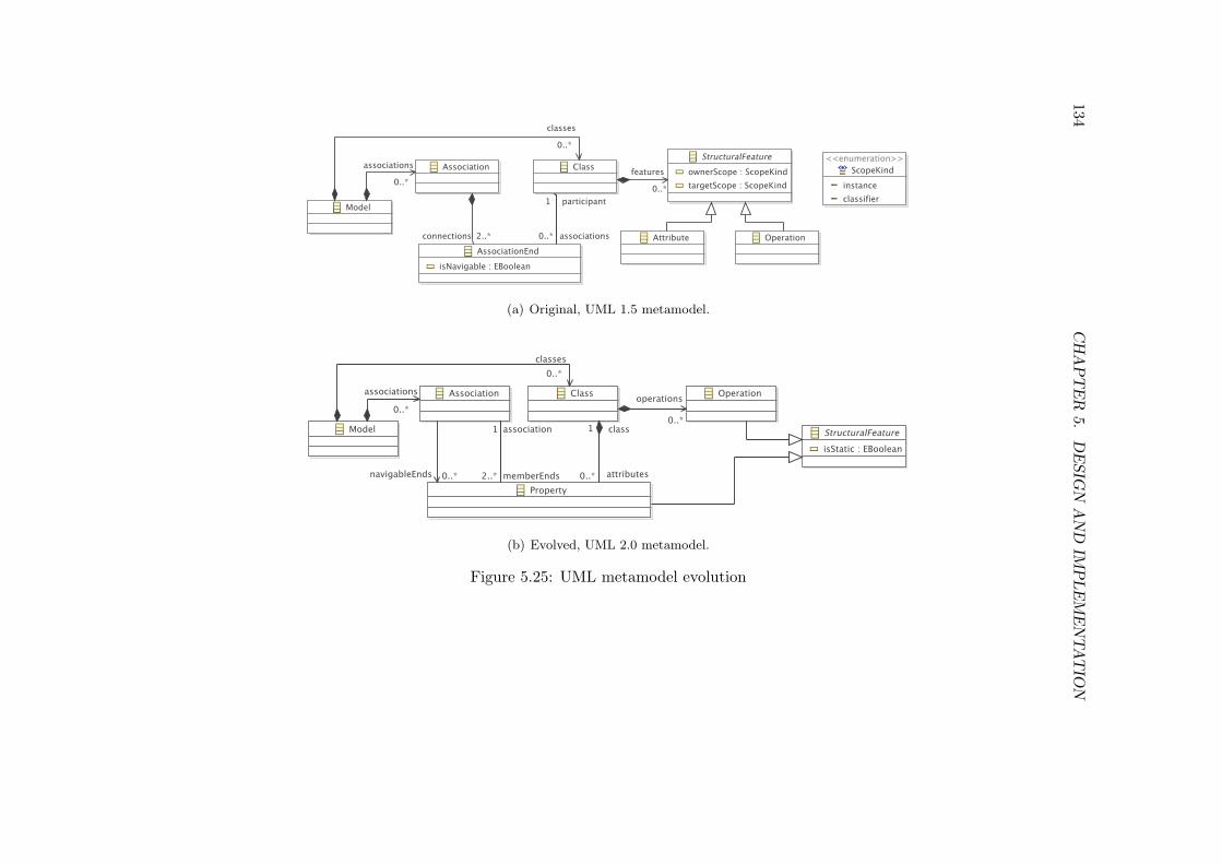
134C
HA
PT
ER
5.D
ESIG
NA
ND
IMP
LE
ME
NTA
TIO
N
(a) Original, UML 1.5 metamodel.
(b) Evolved, UML 2.0 metamodel.
Figure 5.25: UML metamodel evolution

5.4. EPSILON FLOCK: A MODEL MIGRATION LANGUAGE 135
5.4.3 Developing Migration Strategies with Epsilon Flock
To demonstrate the way in which Flock can be used to specify migration strategies,this section provides a guide to the model migration language provided by Flock. Inparticular, the main features of EOL (the core language of Epsilon, which providesa foundation for Flock) are summarised, and then the way in which Flock can beused to specify model migration strategies in response to common types of metamodelevolution is discussed. Finally, guidelines are presented for specifying Flock migrationstrategies when the original and evolved metamodels use type inheritance, because theimplementation of conservative copy provided by Flock affects the way in which suchmigration strategies are specified.
EOL for Migration Strategies
As discussed in Section 5.4.1, EOL is used to specify the guards and bodies of Flockrules. EOL is dynamically and strongly typed, and is a pure object-oriented language:primitives, collections and model elements are objects. The fundamental properties ofEOL and its core functionality are now summarised.
The Any type The universal (top) type in EOL is called Any, and defines operationsfor performing null checks (isDefined and isUndefined), for type-checking (isTy-peOf and isKindOf) and for printing to the standard output stream (print andprintln). In Flock, null and type checks are most often used in the guard of amigrate rule. For example, Listing 5.25 shows a fragment of a migration strategy thatmakes explicit that LabourItems are a special type of JobItem because they alwaysreference an employee. Consequently, migration involves retyping only those JobItemsthat have a non-null value for the feature employee (i.e. employee.isDefined()evaluates to true).
Built-in types EOL provides four primitive types (String, Integer, Real andBoolean) and four collection types (Bag, Sequence, Set and OrderedSet). Thebuilt-in types provide many operations for manipulating primitive and collection values[Kolovos et al. 2006]. For example, Listing 5.26 demonstrates the way in which the St-ring and Sequence types can be used to extract an author’s name and email addressfrom text of the form "Joe Bloggs" <[email protected]>. On line 2,the String#split operation is used to divide the original string into two parts (i.e.a Sequence). On lines 4 and 5 the Collection#first and Collection#lastoperations are used to access each part of the original string, and the String#trimoperation is used to remove superfluous prefix and suffix characters from the substrings.
1 migrate JobItem to LabourItem when: original.employee.isDefined()
Listing 5.25: Using a non-null check to guard a migration rule
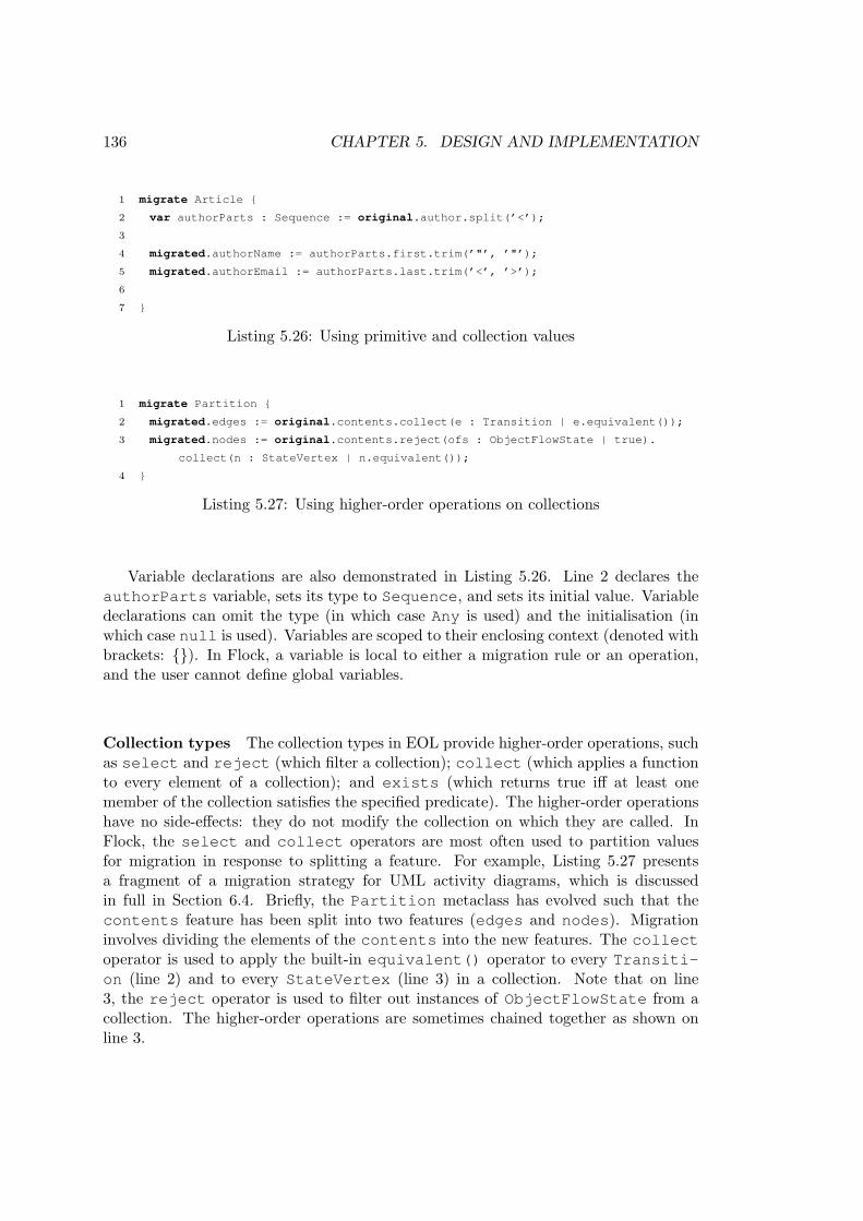
136 CHAPTER 5. DESIGN AND IMPLEMENTATION
1 migrate Article {
2 var authorParts : Sequence := original.author.split(’<’);
3
4 migrated.authorName := authorParts.first.trim(’"’, ’"’);
5 migrated.authorEmail := authorParts.last.trim(’<’, ’>’);
6
7 }
Listing 5.26: Using primitive and collection values
1 migrate Partition {
2 migrated.edges := original.contents.collect(e : Transition | e.equivalent());
3 migrated.nodes := original.contents.reject(ofs : ObjectFlowState | true).
collect(n : StateVertex | n.equivalent());
4 }
Listing 5.27: Using higher-order operations on collections
Variable declarations are also demonstrated in Listing 5.26. Line 2 declares theauthorParts variable, sets its type to Sequence, and sets its initial value. Variabledeclarations can omit the type (in which case Any is used) and the initialisation (inwhich case null is used). Variables are scoped to their enclosing context (denoted withbrackets: {}). In Flock, a variable is local to either a migration rule or an operation,and the user cannot define global variables.
Collection types The collection types in EOL provide higher-order operations, suchas select and reject (which filter a collection); collect (which applies a functionto every element of a collection); and exists (which returns true iff at least onemember of the collection satisfies the specified predicate). The higher-order operationshave no side-effects: they do not modify the collection on which they are called. InFlock, the select and collect operators are most often used to partition valuesfor migration in response to splitting a feature. For example, Listing 5.27 presentsa fragment of a migration strategy for UML activity diagrams, which is discussedin full in Section 6.4. Briefly, the Partition metaclass has evolved such that thecontents feature has been split into two features (edges and nodes). Migrationinvolves dividing the elements of the contents into the new features. The collectoperator is used to apply the built-in equivalent() operator to every Transiti-on (line 2) and to every StateVertex (line 3) in a collection. Note that on line3, the reject operator is used to filter out instances of ObjectFlowState from acollection. The higher-order operations are sometimes chained together as shown online 3.

5.4. EPSILON FLOCK: A MODEL MIGRATION LANGUAGE 137
(a) Original metamodel. (b) Evolved metamodel.
Figure 5.26: Evolution of a unidirectional to a bidirectional reference.
1 migrate Person {
2 migrated.mother := Original!Person.all
3 .selectOne(p|p.gender = "f" and
4 p.children.includes(original))
5 .equivalent();
6 }
Listing 5.28: Using metamodel types
Metamodel types EOL programs can access metamodel types using the syntaxModelName!MetamodelType. Flock migration strategies are typically executed ontwo models (the original and migrated models), and conventionally the two modelsare called Original and Migrated. EOL provides metamodel type operations foraccessing all instances of a type (allInstances) and for checking whether a type canbe instantiated (isInstatiable). In Flock, metamodel types are sometimes usedto navigate between model elements for which there exists no direct reference. Forexample, consider the metamodel evolution in Figure 5.26. The children referencehas been evolved to become bidirectional. Migration involves setting the value of amother reference for every Person. Searching the children reference for every Pe-rson in the model can be achieved using the all property (a syntactic shortcut for theallInstances operation) on the Original!Person metamodel type (Listing 5.28).(Note that selectOne(x) is a syntactic shortcut for select(x).random()).
Instantiation with new Like the primitive and collection types, metamodel typescan be instantiated using the new keyword. Model elements can be deleted (com-pletely removed from a model) using the delete keyword. Flock migration strategiesconventionally have read-only access to the Original model and read-write access toMigrated model, and hence model elements are typically only created in – and deletedfrom – the Migrated model. Listing 5.29 demonstrates using the new keyword to cre-ate elements in the Migrated model. Specifically, one instance of Connection iscreated for every member of the successor reference for each Block.
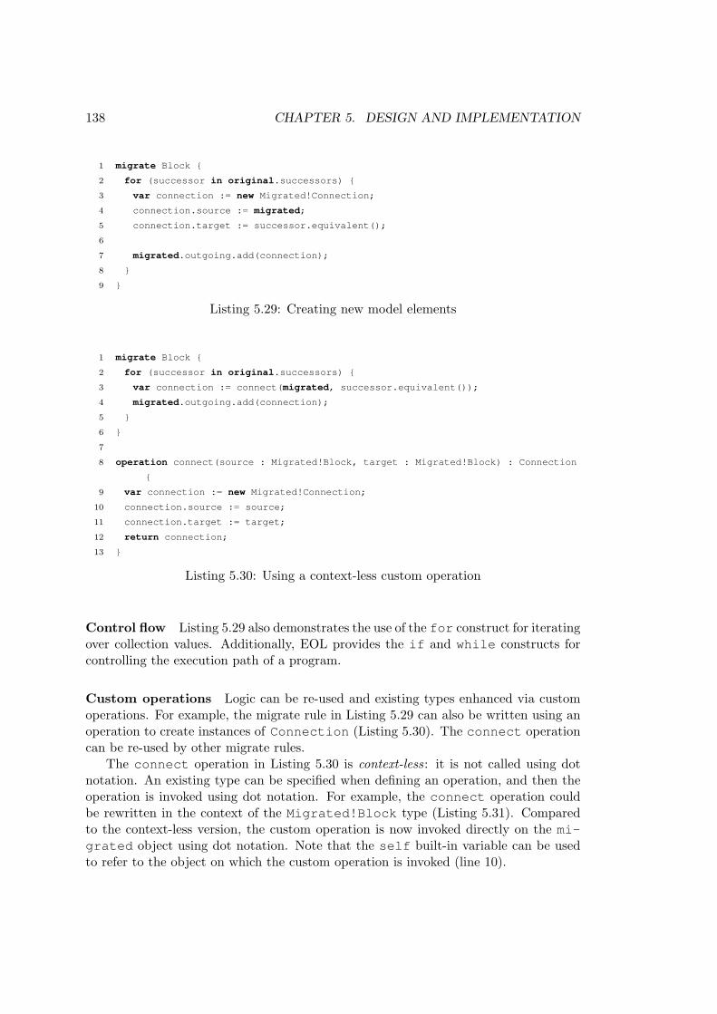
138 CHAPTER 5. DESIGN AND IMPLEMENTATION
1 migrate Block {
2 for (successor in original.successors) {
3 var connection := new Migrated!Connection;
4 connection.source := migrated;
5 connection.target := successor.equivalent();
6
7 migrated.outgoing.add(connection);
8 }
9 }
Listing 5.29: Creating new model elements
1 migrate Block {
2 for (successor in original.successors) {
3 var connection := connect(migrated, successor.equivalent());
4 migrated.outgoing.add(connection);
5 }
6 }
7
8 operation connect(source : Migrated!Block, target : Migrated!Block) : Connection
{
9 var connection := new Migrated!Connection;
10 connection.source := source;
11 connection.target := target;
12 return connection;
13 }
Listing 5.30: Using a context-less custom operation
Control flow Listing 5.29 also demonstrates the use of the for construct for iteratingover collection values. Additionally, EOL provides the if and while constructs forcontrolling the execution path of a program.
Custom operations Logic can be re-used and existing types enhanced via customoperations. For example, the migrate rule in Listing 5.29 can also be written using anoperation to create instances of Connection (Listing 5.30). The connect operationcan be re-used by other migrate rules.
The connect operation in Listing 5.30 is context-less: it is not called using dotnotation. An existing type can be specified when defining an operation, and then theoperation is invoked using dot notation. For example, the connect operation couldbe rewritten in the context of the Migrated!Block type (Listing 5.31). Comparedto the context-less version, the custom operation is now invoked directly on the mi-grated object using dot notation. Note that the self built-in variable can be usedto refer to the object on which the custom operation is invoked (line 10).

5.4. EPSILON FLOCK: A MODEL MIGRATION LANGUAGE 139
1 migrate Block {
2 for (successor in original.successors) {
3 var connection := migrated.connectTo(successor.equivalent());
4 migrated.outgoing.add(connection);
5 }
6 }
7
8 operation Migrated!Block connectTo(target : Migrated!Block) : Connection {
9 var connection := new Migrated!Connection;
10 connection.source := self;
11 connection.target := target;
12 return connection;
13 }
Listing 5.31: Using a custom operation in the context of a metamodel type
1 migrate Account {
2 if (migrated.type.interestRate <> original.interestRate) {
3 var message := ’Which is the correct interest rate for ’ + migrated.type.name
+ ’ accounts?’;
4 var choices := Sequence{migrated.type.interestRate, original.interestRate};
5 var defaultChoice := original.interestRate;
6
7 var chosen := System.getUserInput().choose(message, choices, defaultChoice);
8
9 // Do something with the interest rate selected by the user
10 }
11 }
Listing 5.32: Prompting for user input at runtime
User input Finally, EOL provides a mechanism for obtaining values from the userat runtime. The System built-in variable provides access to a user input library viaits getUser operation. In Flock, user input can be used, for example, to resolveambiguities during migration. For example, Listing 5.32 demonstrates the way inwhich the choose operation prompts the user to select between two possible interestrates for an account type (line 7). Epsilon provides several implementations of the userinput interface for use in different contexts. For example, when running a migrationstrategy in Eclipse, a user is prompted with a graphical user interface (Figure 5.27). Ifa migration strategy is applied in a batch environment, the user might elect to specifyinput via Epsilon’s command line interface for user input.

140 CHAPTER 5. DESIGN AND IMPLEMENTATION
Figure 5.27: Epsilon graphical user interface for selecting between values at runtime.
Specifying Migration Strategies with Epsilon Flock
Some common patterns for specifying migration strategies with Epsilon Flock are nowpresented. In particular, this section suggests migration strategy patterns that can usedin response to some common types of metamodel evolution. The way in which rulesare scheduled by the Flock engine and, in particular, the way in which elements areconservatively copied (Section 5.4.1) by the Flock engine influences the way in whichmigration is specified with Flock.
Recall that conservative copy automatically copies from the original to the migratedmodel only those elements that conform to the both the original and evolved meta-models. For example, model elements will not be automatically copied when their typedoes not exist in – or cannot be instantiated according to – the evolved metamodel.When a model element is conservatively copied from original to migrated model, itsfeature values are also conservatively copied. Like model elements, feature values thatdo not conform to the evolved metamodel are not automatically copied. The semanticsof conservative copy is demonstrated with an example in Section 5.4.2.
Changing feature values The Flock engine executes migrate rules after conserva-tive copy has been used to populate the migrated model. Consequently, migrate rulescan be used to change – or even to delete – feature values that were set in the migratedmodel during conservative copying. Listing 5.33 demonstrates how to change a single-valued feature value (line 3), how to refer to the original value when changing a featurevalue (line 4) and how to add a value to a multi-valued feature value (line 5). Feature

5.4. EPSILON FLOCK: A MODEL MIGRATION LANGUAGE 141
1 migrate Person {
2 -- Changing model values
3 migrated.name := ’Joe Bloggs’;
4 migrated.age := original.age + 1;
5 migrated.luckyNumbers.add(42);
6
7 -- Unsetting model values
8 migrated.address := null;
9 migrated.lotteryNumbers.clear();
10 }
Listing 5.33: Changing and unsetting conservatively copied feature values
1 migrate Person {
2 if (original.id.isInteger()) {
3 migrated.id := original.id.asInteger();
4 } else {
5 (’Warning: no id has been set for ’ + migrated.name).println();
6 }
7 }
Listing 5.34: Casting feature values
values are unset by either assigning null to the feature (single-valued features) as shownon line 8, or by calling the Collection#clear operation (multi-valued features) asshown on line 9.
Casting feature values When the type of a feature has been changed during meta-model evolution, it is sometimes necessary to explicitly convert a value from one type toanother (such as from a String to an Integer). In EOL, primitive types can be castusing the built-in operations starting with as and is. Listing 5.34 demonstrates theuse of the isInteger operation to check whether casting a String to an Integerwill succeed (line 2), and the asInteger operation to perform the cast (line 3).
Migrating reference values Flock provides the equivalent() operation, whichreturns an element in the migrated model (or null) when invoked on an element of theoriginal model, and can be used to migrate reference values. For example, invokingequivalent() on the built-in original variable will always return the value of thebuilt-in migrated variable. Recall the migration rule in Listing 5.35, which was firstintroduced when describing the new keyword in EOL. The rule in Listing 5.35 iteratesover a reference value in the original model, original.successors (line 2). Thebody of the loop has access to an element of the original model via the successorvariable, and creates an instance of the Connection type in the migrated model.

142 CHAPTER 5. DESIGN AND IMPLEMENTATION
1 migrate Block {
2 for (successor in original.successors) {
3 var connection := new Migrated!Connection;
4 connection.source := migrated;
5 connection.target := successor.equivalent();
6
7 migrated.outgoing.add(connection);
8 }
9 }
Listing 5.35: Using equivalent() to access migrated model elements
1 delete Block when: original.name = ’Foo’;
Listing 5.36: Preventing the conservative copy of original model elements
Assigning the value of the successor variable (an element of the original model)to the connection (an element of the migrated model) will result in inter-modelreference from the migrated model to the original model, which is typically incorrectin the context of model migration. Instead, the equivalent() operation is calledon the successor to locate the element of the migrated model that corresponds tosuccessor, which is an element of the original model (line 5).
Creating model elements When metamodel evolution has introduced new classes,migration often involves creating new model elements. With Flock, new model elementsare created in the body of a migrate rule, because their values are either derived fromdata in the original model, or because they must be associated with another element ofthe migrated model. Listing 5.35 demonstrates the use of the new keyword to create anelement in the migrated model (line 3). In this case, the newly created Connectionis associated with the Block that is being migrated (line 4).
Deleting model elements Model migration sometimes involves deleting model el-ements, such as when metamodel evolution has restricted the set of conformant modelelements. (For example, the UML 2.1.2 [OMG 2007a] disallows a type of Struct-uralFeature that was permitted in previous versions of the UML specification). InFlock, a delete rule can be used to prevent an element of the original model frombeing conservatively copied to the migrated model. Listing 5.36 demonstrates the useof a delete rule to ensure that instances of Block with the name Foo are not auto-matically copied from original to migrated model.
Changing the type of model elements Migration sometimes involves changingthe type of existing model elements, such as when a metamodel class has been renamedor split. In Flock, a migrate rule optionally specifies a to part, which is used (during

5.4. EPSILON FLOCK: A MODEL MIGRATION LANGUAGE 143
1 migrate ConnectionPoint to ReadingConnectionPoint when: original.outgoing.
isDefined()
2 migrate ConnectionPoint to WritingConnectionPoint when: original.incoming.
isDefined()
Listing 5.37: Redefining equivalences for the Component model migration.
conservative copy) to determine the target type of an original model element. List-ing 5.37 demonstrates10 the use of two migrate rules to change the type of instances ofConnectionPoint to either ReadingConnectionPoint or WritingConnecti-onPoint. As discussed in Section 5.4.1, rules are prioritised from top to bottom in theFlock source file. Therefore, instances of ConnectionPoint that satisfy the guardsof both rules in Listing 5.37 are retyped to ReadingConnectionPoint rather thanWritingConnectionPoint, because the rule on line 1 takes precedence over therule on line 2.
Migration Strategies for Metamodels that use Inheritance
In addition to the Flock migration strategy patterns described above, users of Flockmust consider one further facet of conservative copy that affect the way in which mi-gration strategies with Flock should be specified. Specifically, conservative copy deter-mines the target type of a model element by locating the first applicable migrate rule(from top to bottom in the source file). This has implications for the way in whichmigrate rules should be ordered, particularly when migrating models that conform tometamodel that use inheritance. The extent to which this implementation detail affectsthe efficacy of Flock is evaluated in Section 6.2.4. Here, the way in which migrationstrategies should be specified in response to the current implementation of conservativecopy in Flock is discussed.
Consider the metamodel in Figure 5.28, which uses inheritance and is based on theGMF metamodel evolution described in Section C.3.1. Suppose that, during metamodelevolution, the type of the figure and accessor attributes is changed from stringto integer, and migration involves deriving the migrated value for these features fromthe length of the original strings. Listing 5.38 demonstrates one way to specify thismigration strategy with Flock. Note that, for the reasons given below, there is no rulespecified on the DiagramElement type, and that the rule for the DiagramLabeltype is placed above the rule for the supertype of DiagramLabel, Node.
Recall that the first applicable migrate rule is used to determine the target type.This has two implications for specifying the migration strategy with Epsilon Flock.Firstly, a migrate rule must not be specified for abstract types (such as DiagramEl-ement) unless a concrete target type is specified via the to part of the migrate rule.
10The migrate rules in Listing 5.37 were first presented in Section 5.4.2 and are taken from the Flockmigration strategy for the process-oriented example described in Appendix B).

144 CHAPTER 5. DESIGN AND IMPLEMENTATION
Figure 5.28: A metamodel that uses inheritance
1 migrate Compartment {
2 migrated.figure := original.figure.length();
3 }
4
5 migrate Connection {
6 migrated.figure := original.figure.length();
7 }
8
9 migrate DiagramLabel {
10 migrated.figure := original.figure.length();
11 migrated.accessor := original.accessor.length();
12 }
13
14 migrate Node {
15 migrated.figure := original.figure.length();
16 }
Listing 5.38: A migration strategy for the metamodel evolution described in Figure 5.28
Hence, a separate migration rule must be specified for each subtype of DiagramEl-ement.
Secondly, a migrate rule is applicable for every model element that instantiatesits original type or, crucially, a subtype of its original type. Hence, a migrate rulespecified for the Node type will also be applicable for instances of DiagramLabel.Consequently, the migrate rule for the DiagramLabel type must be placed above thethe migrate rule for the Node type in the Flock source file. Otherwise, the Node rulewill be applied to all instances of Node and DiagramLabel, and the migrate rulespecific to DiagramLabel will never be applied.
The Flock migration strategy in Listing 5.38 exhibits some duplication due to theway in which migrate rules must be ordered for the current implementation of con-
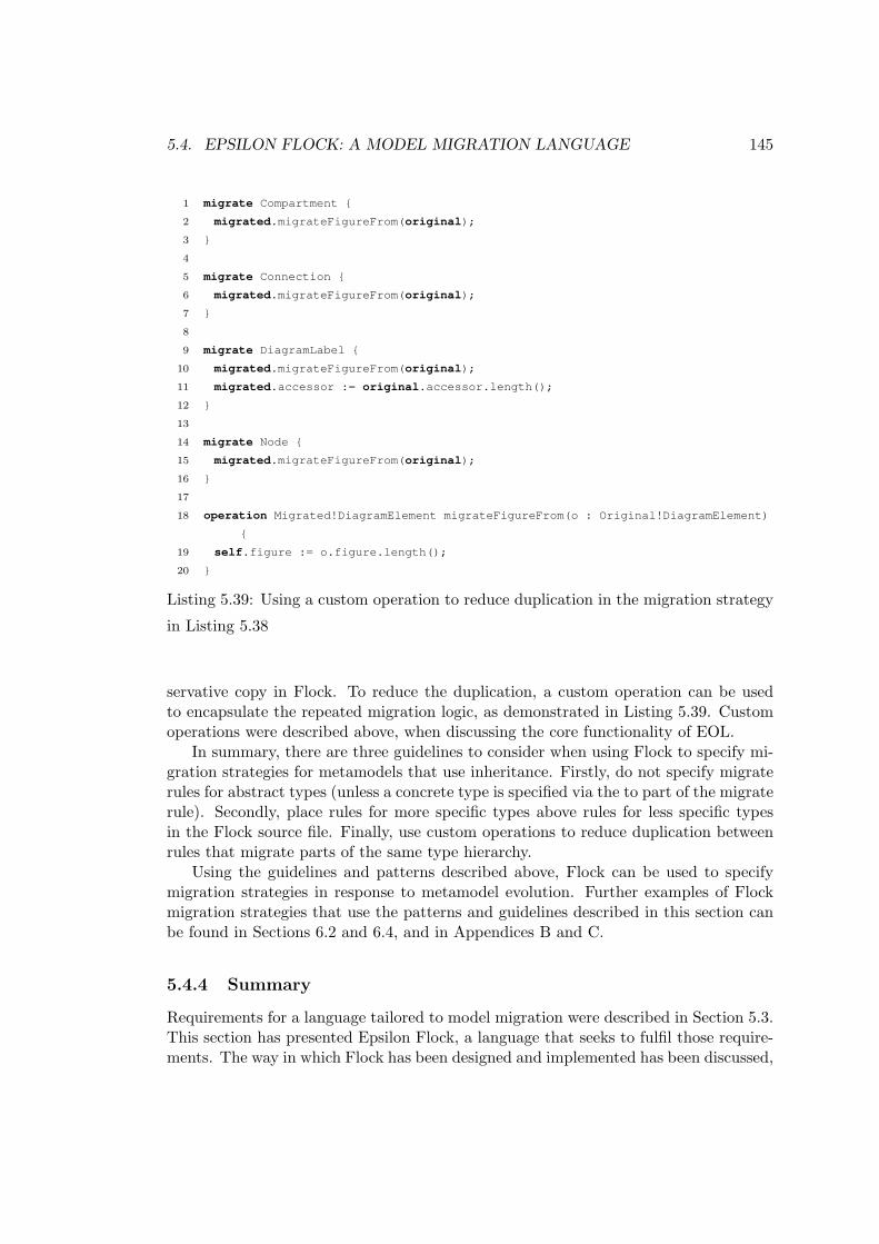
5.4. EPSILON FLOCK: A MODEL MIGRATION LANGUAGE 145
1 migrate Compartment {
2 migrated.migrateFigureFrom(original);
3 }
4
5 migrate Connection {
6 migrated.migrateFigureFrom(original);
7 }
8
9 migrate DiagramLabel {
10 migrated.migrateFigureFrom(original);
11 migrated.accessor := original.accessor.length();
12 }
13
14 migrate Node {
15 migrated.migrateFigureFrom(original);
16 }
17
18 operation Migrated!DiagramElement migrateFigureFrom(o : Original!DiagramElement)
{
19 self.figure := o.figure.length();
20 }
Listing 5.39: Using a custom operation to reduce duplication in the migration strategy
in Listing 5.38
servative copy in Flock. To reduce the duplication, a custom operation can be usedto encapsulate the repeated migration logic, as demonstrated in Listing 5.39. Customoperations were described above, when discussing the core functionality of EOL.
In summary, there are three guidelines to consider when using Flock to specify mi-gration strategies for metamodels that use inheritance. Firstly, do not specify migraterules for abstract types (unless a concrete type is specified via the to part of the migraterule). Secondly, place rules for more specific types above rules for less specific typesin the Flock source file. Finally, use custom operations to reduce duplication betweenrules that migrate parts of the same type hierarchy.
Using the guidelines and patterns described above, Flock can be used to specifymigration strategies in response to metamodel evolution. Further examples of Flockmigration strategies that use the patterns and guidelines described in this section canbe found in Sections 6.2 and 6.4, and in Appendices B and C.
5.4.4 Summary
Requirements for a language tailored to model migration were described in Section 5.3.This section has presented Epsilon Flock, a language that seeks to fulfil those require-ments. The way in which Flock has been designed and implemented has been discussed,

146 CHAPTER 5. DESIGN AND IMPLEMENTATION
Automatic ModellingTool Copy Unset technologies
Ecore2Ecore 3 7 XMIATL 7 3 EMF, MDR, KM3, XML
COPE 3 7 EMFFlock 3 3 EMF, MDR, XML, Z
Table 5.3: Properties of model migration approaches
with a particular focus on the novel source-target relationship, conservative copy (Sec-tion 5.4.1). Several examples of migration strategies constructed in Flock have beenpresented (Section 5.4.2). Further examples are given in Appendix C. Finally, the wayin which metamodel developers can use the model migration language provided byFlock to specify migration strategies was discussed (Section 5.4.3).
Table 5.3 illustrates several characterising differences between Flock and the pre-existing languages presented in Section 5.3. Due to its conservative copying algorithm,Flock is the only language to provide both automatic copying and unsetting. Theevaluation presented in Section 6.2 explores the extent to which automatic copyingand unsetting affect the conciseness of migration strategies.
All of the approaches considered in Section 5.3 support EMF. Both Flock and ATLsupport further modelling technologies, such as MDR and XML. However, ATL doesnot automatically copy model elements that have not been affected by metamodelchanges. Therefore, migration between models of different technologies with ATLrequires extra statements in the migration strategy to ensure that the conformanceconstraints of the target technology are satisfied. Because it delegates conformancechecking to an EMC driver, Flock requires no such checks.
A more thorough examination of the similarities and differences between Flockand other migration strategy languages is provided by the evaluation presented inChapter 6.
5.5 Chapter Summary
Three structures for identifying and managing co-evolution have been designed andimplemented to approach the thesis requirements outlined in Chapter 4. The wayin which modelling frameworks implicitly enforce conformance makes managing non-conformant models challenging, and the proposed metamodel-independent syntax (Sec-tion 5.1) extends modelling frameworks to facilitate the management of non-conformantmodels. The proposed textual modelling notation, Epsilon HUTN (Section 5.2), pro-vides a human-usable notation as an alternative to XMI for performing user-drivenco-evolution. Finally, Epsilon Flock (Section 5.4) contributes a domain-specific lan-guage for describing model migration.
The metamodel-independent syntax is a modelling framework extension that makesexplicit the conformance relationship between models and metamodels. By bind-

5.5. CHAPTER SUMMARY 147
ing models not to their metamodel but to a generic metamodel, the metamodel-independent syntax allows non-conformant models to be managed with modelling toolsand model management operations. Furthermore, conformance checking is providedas a service, which can be scheduled at any time, and not just when models areloaded. The metamodel-independent syntax has been integrated with Concordance[Rose et al. 2010c] to provide a metamodel installation process that automatically re-ports conformance problems, and underpins the implementation of the second structuredescribed in this chapter, a textual modelling notation.
For performing user-driven co-evolution, the textual modelling notation described inSection 5.2 provides an alternative to XMI. Unlike XMI, the notation introduced in thischapter implements the OMG standard for Human-Usable Textual Notation (HUTN)[OMG 2004] and is optimised for human usability. Epsilon HUTN, introduced here,is presently the sole reference implementation of HUTN. Constructing Epsilon HUTNby reusing the metamodel-independent syntax allows Epsilon HUTN to provide incre-mental and background conformance checking, and an XMI-to-HUTN transformationfor loading non-conformant models. Section 6.1 explores the benefits and drawbacksof using the metamodel-independent syntax and Epsilon HUTN together to performuser-driven co-evolution.
The domain-specific language described in Section 5.4, Epsilon Flock, combinesseveral concepts from existing model-to-model transformation languages to form a lan-guage tailored to model migration. In particular, Flock contributes a novel mechanismfor relating source and target model elements termed conservative copy, which is ahybrid of new- and existing-target styles of model-to-model transformation. Flock ex-tends and reuses Epsilon and hence interoperates transparently with several modellingtechnologies via EMC, the Epsilon Model Connectivity layer.
The metamodel-independent syntax, Epsilon HUTN, Epsilon Flock and Concor-dance have been released as part of Epsilon in the Eclipse GMT11 project, which isthe research incubator of arguably the most widely used MDE modelling framework,EMF. By re-using parts of Epsilon, the structures were implemented more rapidly thanwould have been possible when developing the structures independently. In particu-lar, re-using EMC facilitated interoperability of Flock with several MDE modellingframeworks, which was exploited to manage a practical case of model migration inSection 6.4.
11http://www.eclipse.org/gmt

Chapter 6
Evaluation
Chapters 1 and 2 discussed the way in which contemporary MDE development environ-ments provide structures and processes for creating and managing modelling artefacts.For MDE to be applicable in the large and to complex systems, however, MDE de-velopment environments must approach concerns relating to scalability, usability andmanaging evolutionary change. This chapter evaluates the structures and processesdeveloped and described in this thesis with respect to the research hypothesis outlinedin Section 1.4. In particular, the evaluation explores whether the structures and pro-cesses are effective for managing evolutionary change by assessing the extent to whichthey affect developer productivity in co-evolution.
As discussed in Chapter 1, the developed structures and processes are prototypes,and unlikely to be completely fit for industrial use in their current state. As such,the evaluation also aims to determine areas in which the proposed structures andprocesses might be usefully improved by identifying factors that affect their efficacy.The conclusions drawn in this chapter identify benefits and drawbacks of using theproposed structures and processes for managing co-evolution in contemporary MDEdevelopment environments and for industrial software-engineering projects.
Section 4.2.2 identified co-evolution management process, user-driven co-evolution,that had been used in real-world MDE projects and that had not been recognised in theliterature. Chapter 5 described the implementation of two structures tailored for user-driven co-evolution, a metamodel-independent syntax and a textual modelling notation.Using a real-world example of user-driven co-evolution, Section 6.1 assesses the extentto which the dedicated structures proposed in Chapter 5 affect the productivity ofuser-driven co-evolution.
The remainder of the chapter evaluates developer-driven co-evolution (described inSection 4.2.3 and in which a migration strategy is specified in an executable format) andfocuses on Epsilon Flock (Section 5.4), a transformation language tailored for modelmigration. Section 6.2 evaluates the novel source-target relationship strategy imple-mented in Flock, conservative copy, by comparison with two existing source-target re-lationship strategies using co-evolution examples from real-world projects. Sections 6.3and 6.4 evaluate Flock as a whole, using an expert evaluation and a transformation
149

150 CHAPTER 6. EVALUATION
contest, respectively. The transformation contest was judged by members of the MDEcommunity, providing an opportunity for Flock and other transformation tools to beassessed in a peer review.
The evaluation described in Sections 6.3 and 6.4 was performed collaboratively, andthe contributions of others are highlighted in those sections. The work presented in thischapter has been published in [Rose et al. 2010b, Rose et al. 2010d, Rose et al. 2010e].
6.1 Evaluating User-Driven Co-Evolution
Several real-world MDE projects in which user-driven co-evolution has been observedwere reported in Chapter 4, and Chapters 3 and 4 highlighted that no tool supportfor user-driven co-evolution has yet been reported in the literature. To address this,Chapter 5 proposed two structures to support user-driven co-evolution, a metamodel-independent syntax (Section 5.1) and a textual modelling notation (Section 5.2). Thissection explores the extent to which the two structures increase the productivity of user-driven co-evolution, supporting the research hypothesis which stated that integratingdedicated structures and processes with contemporary MDE environments is beneficialin terms of increased productivity.
To explore the hypothesis, several approaches to evaluation could be used. Themetamodel-independent syntax and textual modelling notation are freely available aspart of Epsilon, a component of the Eclipse Modeling Project, so the productivitybenefits of the structures could have been explored by gathering and analysing theopinion of users. However, this approach was discounted because drawing meaningfulconclusions would have needed understanding of each user’s domain, context and back-ground. Evaluation could have been performed with a comprehensive user study thatmeasured the time taken for developers to perform model migration with and withoutthe dedicated structures for user-driven co-evolution. However, locating developers andco-evolution examples was not possible in the available time. Instead, evaluation wasconducted by comparing two approaches to user-driven co-evolution using an examplefrom a real-world MDE project. The first approach uses only the tools available in theEclipse Modeling Framework (EMF); while the second approach uses EMF togetherwith the metamodel-independent syntax and textual modelling notation introduced inChapter 5.
Section 6.1.1 summarises Section 4.2.2, which described the challenges to produc-tivity faced by developers while performing user-driven co-evolution with EMF. Sec-tion 6.1.2 introduces the example of user-driven co-evolution used to perform the eval-uation. In Sections 6.1.3 and 6.1.4, the two approaches to user-driven co-evolution aredemonstrated. The section concludes by comparing the two approaches and highlight-ing ways in which the metamodel-independent syntax and textual modelling notationincrease developer productivity in the context of user-driven co-evolution.

6.1. EVALUATING USER-DRIVEN CO-EVOLUTION 151
6.1.1 Challenges for Performing User-Driven Co-Evolution
Two productivity challenges for performing user-driven co-evolution in contemporaryMDE environments were identified in Section 4.2.2. Firstly, model storage represen-tations are not optimised for use by humans, and so user-driven co-evolution – whichtypically involves changing models by hand – is made error-prone and time consuming.Secondly, the multi-pass parsers used to load models in contemporary MDE environ-ments make user-driven co-evolution an iterative process, because not all conformanceerrors are reported in the first pass. The identification of these productivity challengesled to the derivation of the following research requirement in Section 4.3: This thesismust demonstrate a user-driven co-evolution process that enables the editing of non-conformant models without directly manipulating the underlying storage representationand provides a conformance report for the original model and evolved metamodel.
Two of the structures presented in Chapter 5 provide the foundation for fulfillingthe above research requirement. The first, a metamodel-independent syntax, facilitatesthe conformance checking of a model against any metamodel. The second structure, thetextual modelling notation Epsilon HUTN, allows models to be managed in a formatthat is reputedly easier for humans to use than XMI, the canonical model storageformat [OMG 2004].
To fulfil the above research requirement, this section applies the metamodel-ind-ependent syntax and the textual modelling notation to demonstrate that user-drivenco-evolution can be performed without encountering the challenges to productivitydescribed above. To this end, an example of co-evolution is used to show the way inwhich user-driven co-evolution might be achieved with and without the metamodel-independent syntax and Epsilon HUTN.
6.1.2 Co-Evolution Example
The evaluation uses the co-evolution example taken from collaborative work with AdamSampson, then a Research Associate at the University of Kent. The purpose of the col-laboration was to build a prototypical editor for graphical models of programs writtenin process-oriented programming languages, such as occam-π [Welch & Barnes 2005].The graphical models would provide a standard notation for describing process-orientedprograms. Part of the example was used to describe Epsilon Flock in 5.4.2.
The collaboration with Sampson was selected for the evaluation presented here forseveral reasons. Firstly, the work involved constructing a graphical model editor,a common MDE development activity [Amyot et al. 2006]. Secondly, the editor wasdeveloped in an incremental and iterative manner, and involved several different typesof change to the metamodel, some of which affected conformance. Finally, a relativelysmall number of models were constructed during the collaboration, and hence a user-driven approach to managing co-evolution was more suitable than a developer-drivenapproach for this example.
The graphical model editor was developed using a MDE approach. A metamodelcaptures the abstract syntax of process-oriented programming languages, and code for

152 CHAPTER 6. EVALUATION
a graphical model editor is automatically generated from the metamodel.The final version of the graphical model editor is shown in Figure 6.1. The editor
captures the three primary concepts used to specify process-oriented programs: pro-cesses, connection points and channels. Processes, represented as boxes in the graphicalnotation, are the fundamental building blocks of a process-oriented program. Channels,represented as lines in the graphical notation, are the mechanism by which processescommunicate, and are unidirectional. Connection points, represented as circles in thegraphical notation, define the channels on which a process can communicate. Becausechannels are unidirectional, connection points are either reading (consume messagesfrom the channel) or writing (generate messages on the channel). Reading (writing)connection points are represented as white (black) circles in the graphical notation.
Figure 6.1: Final version of the prototypical graphical model editor.
The graphical model editor was implemented using EMF. The metamodel was spec-ified in Ecore, the metamodelling language of EMF, and the graphical editor was gen-erated from the metamodel using GMF. Section 2.3 describes in more detail the wayin which EMF and GMF can be used to specify metamodels and to generate graphicalmodel editors.
The process-oriented metamodel was developed iteratively, and the six iterationsare described in Appendix B. During each iteration, the metamodel was changed. The

6.1. EVALUATING USER-DRIVEN CO-EVOLUTION 153
evaluation described here uses an example of metamodel changes from the fifth iterationof the project. The way in which development proceeded during that iteration isdescribed in Section B.5 and summarised below.
Aim of Iteration 5
Iteration 5 of the process-oriented example was used to describe Epsilon Flock in 5.4.2.The purpose of the iteration was to refine the way in which connection points wererepresented. At the start of the iteration, the graphical model editor could be usedto draw processes, channels and connection points. However, no distinction was madebetween reading and writing connection points.
Figure 6.2 shows a model represented in the graphical model editor before theiteration began. The model contains two processes (depicted as boxes), P1 and P2,one channel (depicted as a line), a, and two connection points (depicted as circles), a!and a?.
Figure 6.2: The graphical editor at the start of the iteration.
The aim of the iteration was to distinguish between reading and writing connectionpoints in the graphical notation. The former are used to receive messages, and the latterto send messages. In Figure 6.2, a? is intended to represent a reading connection point,

154 CHAPTER 6. EVALUATION
and a! a writing connection point. Sampson and I decided that the editor should bechanged so that black circles would be used to represent writing connection points, andwhite circles to represent reading connection points. At the end of the iteration themodel shown in Figure 6.2 would be represented as shown in Figure 6.3. Furthermore,the editor would ensure that a? was used only as the reader of a channel, and a! onlyas the writer of a channel. Before the iteration started, the editor did not enforce thisconstraint.
Figure 6.3: The graphical editor at the end of the iteration.
Metamodel changes during Iteration 5
Before the iteration started, the metamodel, shown in Figure 6.4(a), did not distinguishbetween reading and writing ConnectionPoints. A ConnectionPoint could beassociated with a Channel via the reader or writer reference of Channel, but thetype of a ConnectionPoint was not specified explicitly.
The way in which connection points were modelled was changed, resulting in themetaclasses shown in Figure 6.4(b). ConnectionPoint was made abstract, andtwo subtypes, ReadingConnectionPoint and WritingConnectionPoint, wereintroduced. The reader and writer references of Channel were changed to refer

6.1. EVALUATING USER-DRIVEN CO-EVOLUTION 155
to the new subtypes. The evolved metamodel correctly prevented the use of a Conn-ectionPoint as both a reader and a writer.
(a) Part of the original metamodel.
(b) Part of the evolved metamodel.
Figure 6.4: Process-oriented metamodel evolution.
Following the metamodel changes, a new version of the graphical editor was gen-erated automatically from the metamodel using GMF. An annotation – not shownin Figure 6.4(b) – on the WritingConnectionPoint class was used to indicate toGMF that black circles were to be used to represent writing connection points in thegraphical notation.
Testing during Iteration 5
Testing the new version of the graphical editor highlighted the need for model migration.Attempting to load existing models, such as the one shown in Figure 6.2, caused anerror because ConnectionPoint was now an abstract class. Any model specifyingat least one connection point no longer conformed to the metamodel. Model migrationwas performed to re-establish conformance and to allow the models to be loaded.
Several models, presented in Appendix B, had been constructed when testing pre-vious versions of the graphical editor. The models were used during each iteration toensure that any changes had not introduced regressions. After the metamodel changesdescribed above, the test models could no longer be loaded and required migration. A

156 CHAPTER 6. EVALUATION
developer-driven co-evolution approach was not suitable for the development of process-oriented editor because only a few small models required migration in each iteration.A user-driven co-evolution approach was used instead, but, as no structures dedicatedto user-driven co-evolution were available, co-evolution was performed by manuallyediting the storage representation of models.
The sequel describes the way in which migration was performed during the develop-ment of the process-oriented metamodel, without dedicated structures for performinguser-driven co-evolution. Section 6.1.4 describes the way in which migration couldhave been performed using two of the structures presented in Chapter 5. The sectionconcludes by comparing the two approaches.
6.1.3 User-Driven Co-Evolution with EMF
During the development of the process-oriented metamodel, no dedicated structures forperforming user-driven co-evolution were available. Instead, migration was performedusing only those tools available in EMF, as described below.
Migration with EMF involved identifying and fixing conformance errors, using theworkflow shown in Figure 6.5. The workflow was first discussed in Chapter 4. Whenthe user attempts to load a model, EMF automatically checks the conformance of themodel. If the model does not conform to its metamodel, loading fails. To re-establishconformance, the user must edit by hand the underlying storage representation of themodel, XMI. Recall that co-evolution is an iterative process because EMF uses a multi-pass XMI parser and cannot report all categories of conformance problem in the firstpass.
One of the test models, shown in Figure 6.2, is now used to illustrate the way inwhich user-driven co-evolution was performed using the workflow shown in Figure 6.5.For the test model shown in Figure 6.2, the conformance problems shown in the bottompane (and by the error markers in the left-hand margin of the top pane) of Figure 6.6were reported by EMF. For example, the first conformance problem reported is shownin the tooltip in Figure 6.6, and states that a ClassNotFoundException was en-countered because the “Class ‘ConnectionPoint’ is not found or is abstract.”
The conformance problems were fixed by editing the XMI shown in Figure 6.6,producing the XMI shown in Figure 6.7. The type of each connection point elementwas changed to either ReadingConnectionPoint or WritingConnectionPoi-nt. The former was used when the connection point was referenced via the readerreference of Channel, and the latter otherwise. The reconciled XMI is shown inFigure 6.7. On lines 4 and 7, the connection point model elements have been changedto include xsi:type attributes, which specify whether the connection point shouldinstantiate ReadingConnectionPoint or WritingConnectionPoint.
Reconciling the conformance problems by editing the XMI required considerableknowledge of the XMI specification. For example, the xsi:type attribute is usedto specify the type of the connection point model elements. In fact, it must be in-cluded for those model elements. However, for the other model elements in Figure 6.7the xsi:type attribute is not necessary, and is omitted. When and how to use

6.1. EVALUATING USER-DRIVEN CO-EVOLUTION 157
Attempt to load model with
graphical editor
Does EMF report any conformance problems?
No
YesEdit XMI of
non-conformant model
Figure 6.5: User-driven co-evolution with EMF
the xsi:type attribute is discussed further in the sidebar, in the XMI specification[OMG 2007c], and by the developers of EMF [Steinberg et al. 2008]. EMF abstractsaway from XMI, and typically users do not interact directly with XMI. Therefore, itmay be reasonable to assume that EMF users might not be familiar with XMI, andimplementation details such as the xsi:type attribute.
During the development of the process-oriented editor, some mistakes were madewhen the XMI of the test models was edited by hand. For example, the wrong sub-type of ConnectionPoint was used as the type of several connection point modelelements. The mistake occurred because XMI identifies model elements using an offsetfrom the root of the document. For example, consider the XMI shown in Figure 6.7.The channel on line 9 specifies the value “//@processes.1/@connectionPoints.0” for itsreader attribute. The value is an XMI path referencing the first connection point(“@connectionPoints.0”) contained in the second process (“@processes.1”) of this doc-ument (“//”); in other words the connection point on line 7. One of Sampson’s modelscontained many channels and connection points and incorrectly counting the connec-tion points in the model led to several mistakes during the manual editing of the XMI.Each time a mistake was made when reconciling the XMI by hand, another loop aroundthe workflow shown in Figure 6.5 was required.
As demonstrated above, migration using only the tools provided by EMF can beiterative and error-prone. The sequel demonstrates that, by using the dedicated struc-tures described in Chapter 5, migration can be performed in one iteration, withoutrequiring the developer to switch between conformance reporting and model migra-tion tools. In addition, the sequel suggests how the mistake described above might beavoided by using Epsilon HUTN rather than XMI for manually migrating models.

158 CHAPTER 6. EVALUATION
Figure 6.6: XMI prior to migration
6.1.4 User-Driven Co-Evolution with Dedicated Structures
Chapter 5 describes two structures that can be used to perform user-driven co-evolution.Here, the functionality of the two structures, a metamodel-independent syntax and atextual modelling notation, is summarised. Subsequently, an approach that uses themetamodel-independent syntax and the textual modelling notation for migrating themodel from the process-oriented example is presented. The model migration exam-ple presented in this section was performed retrospectively by the author after theprocess-oriented editor was completed, and demonstrates how migration might havebeen achieved with dedicated structures for user-driven co-evolution. The sequel com-pares the user-driven co-evolution approach presented in this section with the approachpresented in Section 6.1.3.
The metamodel-independent syntax presented in Section 5.1 allows non-conformant

6.1. EVALUATING USER-DRIVEN CO-EVOLUTION 159
Figure 6.7: XMI after migration
The xsi:type attributeIn XMI, each model element must indicate the metaclass that it instantiates. Typ-ically, the xsi:type attribute is used for this purpose. For example, the modelelement on line 4 of Figure 6.7 instantiates the metaclass named WritingConn-ectionPoint. To reduce the size of models on disk, the XMI specification allowstype information to be omitted when it can be inferred. For example, line 9 ofFigure 6.7 defines a model element that is contained in the channels referenceof a Process. Because the channels reference can contain only one type ofmodel element (Channel), the xsi:type attribute can be omitted, and the typeinformation is inferred from the metamodel.

160 CHAPTER 6. EVALUATION
models to be loaded with EMF, and for the conformance of models to be checkedagainst any metamodel. Epsilon HUTN, the textual modelling notation presented inSection 5.2 is underpinned by the metamodel-independent syntax and is an alternativeto XMI for representing models in a textual format. Together, the two structures canbe used for performing user-driven co-evolution using the workflow shown in Figure 6.8.The workflow was first discussed in Chapter 5. First, the user attempts to load a modelin the graphical editor. If the model is non-conformant and cannot be loaded, the userclicks the “Generate HUTN” menu item, and the model is loaded with the metamodel-independent syntax and then a HUTN representation of the model is generated byEpsilon HUTN. The generated HUTN is presented in an editor that automaticallyreports conformance problems using the metamodel-independent syntax. The useredits the HUTN to reconcile conformance problems, and the conformance report isautomatically updated as the user edits the model. When the conformance problemsare fixed, XMI for the conformant model is automatically generated, and migration iscomplete. The model can then be loaded in the graphical editor.
Attempt to load model with
graphical editor
Does EMF report any conformance problems?
No
YesInvoke
XMI-to-HUTN transformation
Edit HUTN of non-conformant
model
Figure 6.8: User-driven co-evolution with dedicated structures
The way in which the workflow shown in Figure 6.8 was used to perform user-drivenco-evolution for the process-oriented metamodel is now demonstrated. For the modelshown in Figure 6.2, the HUTN shown in Figure 6.9 was generated by invoking the au-tomatic XMI-to-HUTN transformation. The HUTN development tools automaticallypresent any conformance problems, as shown in the bottom pane (and the left-handmargin of the top pane) in Figure 6.9.
Conformance problems are reconciled manually by the user, who edits the HUTNsource. Conformance is automatically checked whenever the HUTN is changed. Forexample, Figure 6.10 shows the HUTN editor when migration is partially complete.Some of the conformance problems have been reconciled, and the associated error-markers are no longer displayed in the left-hand margin.
When no conformance errors remain, Epsilon HUTN automatically generates XMIfor reconciled model, and the user can now successfully load the migrated model withthe graphical editor.

6.1. EVALUATING USER-DRIVEN CO-EVOLUTION 161
Figure 6.9: HUTN source prior to migration
6.1.5 Comparison
To suggest ways in which dedicated structures for user-driven co-evolution might in-crease developer productivity, the two user-driven co-evolution approaches demon-strated above are now compared. The first approach, described in Section 6.1.3, usesonly those tools available in EMF for performing user-driven co-evolution, while thesecond approach, described in Section 6.1.4 uses two of the structures introduced inChapter 5. Applying the approaches to the process-oriented example highlighted dif-ferences between the modelling notations used, and the way in which conformanceproblems were reported.
Differences in modelling notation
For reconciling conformance problems, the two approaches used different modellingnotations, XMI and Epsilon HUTN. Differences in notation that might influence devel-oper productivity during user-driven co-evolution are now discussed. However, further

162 CHAPTER 6. EVALUATION
Figure 6.10: HUTN source part way through migration
work is required to more rigorously explore the extent to which developer productivityis affected by the modelling notation, as discussed in Section 6.1.6.
The way in which the type of a model element is specified is different in XMIand HUTN. In XMI, type information can be omitted in some circumstances, butmust be included in others. In HUTN, type information is mandatory for every modelelement. Consequently, every HUTN document contains examples of how type infor-mation should be specified, whereas XMI documents may not.
Reference values use paths in XMI (such as //@processes.1/@connectionPo-ints.0) and names (such as a?) in HUTN. XMI paths are constructed in terms ofa document’s structure and, as such, rely on implementation details. The name ofa model element, on the other hand, is specified in the model, and does not rely onany implementation details. Consequently, it is conceivable that fewer mistakes willbe made during user-driven co-evolution when reference values are specified by namerather than with the structural details of a model.

6.1. EVALUATING USER-DRIVEN CO-EVOLUTION 163
Differences in conformance reports
The two approaches differ in the way in which conformance problems were reported,and, as a consequence, the first approach was iterative and the second was not. The dif-ferences might influence developer productivity during user-driven co-evolution. Again,further work is required to rigorously explore the extent to which developer productivityis affected by the differences in conformance reporting, as discussed in Section 6.1.6.
With EMF, user-driven co-evolution is an iterative process. Conformance errorsare fixed by the user, who then reloads the reconciled model (with, for example, agraphical editor). Each time the model is loaded, further conformance problems mightbe reported when, for example, the user makes a mistake when reconciling the model.By contrast, the implementation of HUTN described in Section 5.2 uses a backgroundcompiler that checks conformance while the user edits the HUTN source. When theuser makes a mistake reconciling the HUTN source, the error is reported immediately,and does not require the model to be loaded in the graphical editor.
Although not demonstrated here, user-driven co-evolution would, for some typesof metamodel changes, remain an iterative process even if EMF performed confor-mance checking in the background. Because EMF uses a multi-pass parser, some typesof conformance problem are reported before other types. For example, conformanceproblems relating to multiplicity constraints (e.g. a process does not specify a name,but name is a mandatory attribute) are reported after all other types of conformanceproblem. When several types of conformance problem have been affected by meta-model changes, user-driven co-evolution with EMF would remain an iterative process.Single-pass, background parsing is required to display all conformance problems whilethe user migrates a model.
6.1.6 Towards a more thorough comparison
Extensions to the evaluation of user-driven co-evolution are now discussed. In partic-ular, alternative comparison methods might enable a more rigorous exploration of theways in which dedicated structures for performing user-driven co-evolution influencedeveloper productivity.
A comprehensive user study, involving hundreds of users, is one means for exploringthe extent to which productivity varies when dedicated structures are used to performuser-driven co-evolution. Ideally, participants for the study would constitute a largeand representative sample of the users of EMF. Productivity might be measured bythe time taken to perform co-evolution. To remove a potential source of bias, severalexamples of co-evolution might be used.
Locating a reasonable number of participants and co-evolution examples for a com-prehensive user study was not feasible in the context of this thesis. Nevertheless, thecomparison presented in Section 6.1.5 suggests that productivity might be increasedwhen using dedicated structures for user-driven co-evolution. By demonstrating an ap-proach to user-driven co-evolution that uses dedicated structures, this thesis provides afoundation for further, more rigorous evaluation. For example, the HUTN specification

164 CHAPTER 6. EVALUATION
[OMG 2004] makes claims about the human-usability of the notation, but the usabilityof HUTN has not been studied or compared with other modelling notations. EpsilonHUTN (Section 5.2) is a reference implementation of HUTN and, as demonstrated bythe evaluation presented here, facilitates the evaluation of HUTN and the comparisonof HUTN to other modelling notations, such as XMI.
6.1.7 Summary
This section has demonstrated two approaches to user-driven co-evolution using a co-evolution example from a project in which a graphical model editor was created forprocess-oriented programs. The first approach used the structures available in EMFalone, while the second approach used two of the structures described in Chapter 5.Comparing the two approaches highlighted differences between the way in which confor-mance problems were reported and between the modelling notations used to reconcileconformance problems. The comparison described in Section 6.1.5 suggests that devel-oper productivity might be increased by using the second approach, but, as discussedin Section 6.1.6, further work is required to more rigorously evaluate this claim.
6.2 Evaluating Conservative Copy
In contrast to the previous section, this section focuses on developer-driven co-evolution,in which migration is specified in a programming language. As discussed in Chapter 4,often a model-to-model (M2M) transformation language is used to specify migration.The M2M languages typically used to specify migration vary and, in particular, use dif-ferent approaches to relating source and target model elements. This section evaluatesthe novel source-target relationship implemented in Flock (Section 5.4), conservativecopy, by comparison to new-target and existing-target source-target relationships, whichhave been used for model migration in [Cicchetti et al. 2008, Garces et al. 2009]) andin [Herrmannsdoerfer et al. 2009a, Hussey & Paternostro 2006]) respectively.
The evaluation performed in this section aims to demonstrate that migration strate-gies are more concise when written with a M2M language that uses conservative copyrather than when written with a M2M language that uses new- or existing-target. Ar-guably, more concise migration strategies lead to increased developer productivity inmodel migration. In manual specification approaches, migration strategies are writtenby hand and a concise language is likely to increase productivity because less codeis written. In operator-based and inference approaches, migration strategies may bepresented to the user to facilitate selection between feasible alternatives, and a conciselanguage could increase productivity because less code must be read to comprehenda migration strategy. Other factors that might influence productivity, such as thecomprehensibility of a migration strategy are not considered in this section, but in thesequel in which Epsilon Flock is evaluated by comparison with other co-evolution tools.
Conciseness might be measured in many ways. For instance, the number of lines ofcode have been used to argue that more concise software components indicate a highdegree of inter-component re-use [Kolovos 2009]. In that context, the number of lines

6.2. EVALUATING CONSERVATIVE COPY 165
of code is an appropriate measure because the software components were written ina single programming language. The conciseness and understandability of programscan be approximated by determining the ratio of operators (language constructs) tooperands (data) [Halstead 1977]. Halstead’s Metrics are calculated from programminglanguage constructs and, consequently, are affected by variations in programming lan-guages. Here, counting lines of code and Halstead’s Metrics are inappropriate becauseno single language implements the three styles of source-target relationship that are tobe compared.
Instead, conciseness is measured by counting the frequency of model operations,atomic program statements that are used to manipulate the target (migrated) model.Model operations were specified in a language-independent manner and then mappedonto language-specific constructs to perform the counting. Therefore, the hypothesis forthe comparison was: specifying a migration strategy with conservative copy requires nomore model operations than when new-target or when existing-target are used instead.The results presented in Section 6.2.4 corroborate the hypothesis and highlight somelimitations of the implementation of conservative copy in Flock.
The remainder of this section briefly recaps the theoretical differences between thethree styles of source-target relationship (Section 6.2.1), describes the co-evolution ex-amples and languages used in the comparison (Section 6.2.2), and details the compar-ison method (Section 6.2.3). Finally, the results of the comparison (Section 6.2.4) areused to support the claims made above, and to highlight limitations of the conservativecopy implementation provided by Flock.
6.2.1 Styles of Source-Target Relationship
Two styles of source-target relationship, new-target and existing-target, are used inexisting approaches to model migration, and a third is proposed in this thesis, conser-vative copy. The differences between the source-target relationships were discussed inChapter 5 and are now summarised.
With a new-target source-target relationship, the migrated model is created afreshby the model migration strategy. The model migration language does not automaticallycopy any part of the original model to the migrated model. Consequently, any modelelements that are not affected by metamodel evolution must be explicitly copied fromoriginal to migrated model.
With an existing-target source-target relationship, the migrated model is initialisedas a copy of the original model. Prior to execution of the migration strategy, themigrated and original models are identical. Elements that no longer conform to theevolved metamodel might have been copied automatically from original to migratedmodel and, consequently, the migration strategy may need to delete model elements.
This thesis proposes a third style of source-target relationship termed conservativecopy, which is a hybrid of new- and existing-target source-target relationships. Priorto the execution of the migration strategy, only those model elements that conform tothe evolved metamodel are copied from original to migrated model
To compare the styles of source-target relationship, the evaluation uses a reference
166 CHAPTER 6. EVALUATION
implementation of each style. The reference implementations are model-to-model trans-formation languages, which automatically copy model elements according to the styleof source-target relationship. Flock, for example, provides a reference implementationof conservative copy.
6.2.2 Artefacts
To evaluate conservative copy, five examples of co-evolution taken from three projects,and three reference implementations of source-target relationships were used. The co-evolution examples and the selection process for the reference implementations are nowdiscussed.
Co-evolution Examples
Conservative copy was designed in response to analysis of co-evolution examples, asdiscussed in Chapters 4 and 5. To reduce contamination of the comparison, the co-evolution examples used were distinct from those used to design conservative copy. Theexamples used for evaluating conservative copy are now summarised, and more detailscan be found in Appendix C.
Two examples were taken from the Newsgroup project, which performs statisti-cal analysis of NNTP newsgroups, developed by Dimitris Kolovos, a lecturer in thisdepartment. One example was taken from changes made to UML (the Unified Model-ing Language) between versions 1.4 [OMG 2001] and 2.2 [OMG 2007b] of the spec-ification. Two examples were taken from GMF (Graphical Modeling Framework)[Gronback 2009], an Eclipse project for generating graphical model editors.
For the newsgroup and GMF projects, the co-evolution examples were identifiedfrom source code management systems. The revision history for each project was ex-amined, and metamodel changes were located. The intended migration strategy wasdetermined by speaking with the developer (for the Newsgroup project) and by exam-ining examples and documentation (for GMF). The co-evolution example taken fromUML was identified from the list of changes in the UML 2.2 specification [OMG 2007b],and by discussion with other UML users as described in Section 6.4.
For interoperability with the three reference implementations used in the com-parison, the UML co-evolution was adapted. The original (UML 1.4 [OMG 2001])metamodel is specified in XMI 1.2 [OMG 2007c], which is not supported by two of thereference implementations. The part of the UML 1.4 relating to activity graphs wasreconstructed by the author in XMI 2.1 and used in place of the XMI 1.2 version. Thereconstructed metamodel was checked by several UML users and was used in the expertevaluation described in Section 6.4, where the reconstructed metamodel is discussedfurther.
Reference Implementations Used in the Comparison
A formal semantics has not been specified for new-target, existing-target and con-servative copy, and therefore the comparison reported in this section was performed
6.2. EVALUATING CONSERVATIVE COPY 167
using a reference implementation of each source-target relationship. Reference imple-mentations for new- and existing-target were selected from the implementations usedby existing approaches to model migration and compared to the implementation ofconservative copy provided by Flock.
New-target As far as the author is aware, the Atlas Transformation Language (ATL)is the only new-target M2M transformation language that has been used for modelmigration. Existing new-target model migration approaches use higher-order transfor-mations specified in ATL [Cicchetti et al. 2008, Garces et al. 2009]. As such, ATL wasused in the evaluation as the reference implementation of new-target.
Existing-target Two approaches to migration use existing-target transformations.In COPE [Herrmannsdoerfer et al. 2009a], migration strategies can be hand-written inGroovy when no co-evolutionary operator is applicable. COPE provides six Groovyfunctions for interacting with model elements, such as set, for changing the valueof a feature, and unset, for removing all values from a feature. In this section, theterm Groovy-for-COPE is used to refer to the combination of the Groovy program-ming language and the functions provided by COPE for use in hand-written migrationstrategies. In Ecore2Ecore [Hussey & Paternostro 2006], migration is performed whenthe original model is loaded, effectively an existing-target approach. For the compari-son performed in this section, Groovy-for-COPE was preferred to Ecore2Ecore becausethe latter is not as expressive1 and cannot be used for migration in the co-evolutionexamples considered here.
In summary, the comparison described in this section uses ATL for investigatingnew-target, Groovy-for-COPE for existing-target, and Flock for conservative copy.
6.2.3 Method
The comparison involved constructing migration strategies in each of the referenceimplementations (ATL, Groovy-for-COPE and Flock), identifying and counting modeloperations, and analysing the results. Following the selection of co-evolution examplesand reference implementations, the author wrote a migration strategy for each co-evolution example in each of the reference implementations. The intended migrationstrategy was determined from models available in the source code management systemof the co-evolution example (Newsgroup and GMF projects), or (for the UML example)by referring to the UML specification and discussing ambiguities with other UML users,as described in Section 6.4.
Next, a set of model operations were identified in a language independent mannerand then mapped onto language constructs in ATL, Groovy-for-COPE and Flock. Thecounting of model operations was then automated by implementing a counting program,
1Communication with Ed Merks, Eclipse Modeling Project leader, 2009, avail-able at http://www.eclipse.org/forums/index.php?t=tree&goto=486690&S=b1fdb2853760c9ce6b6b48d3a01b9aac

168 CHAPTER 6. EVALUATION
which was tested and used to further develop the comparison technique. Finally, thecounting program was executed on the evaluation examples and the results investigated(Section 6.2.4).
Because the author is more familiar with Flock than with ATL and Groovy-for-COPE, the comparison method has an obvious drawback: the migration strategieswritten in the latter two languages might be more concise if they were written by thedevelopers of ATL and Groovy-for-COPE. The evolutionary operators built into COPEprovide many examples of migration strategy code written by the developer of COPEand, where possible, this code was re-used.
Language-Independent Model Operations
The way in which model operations were identified and counted is now described.Four types of model operation were considered for inclusion in the evaluation: modelelement creation and deletion operators, and model value assignment and unassignmentoperators.
Creation and deletion operators are used to create or delete model elements in themigrated model. Assignment and unassignment operators are used to set or unset datavalues in the migrated model. Typically, assignment operators are used for copyingvalues from the original to the migrated model.
Deletion and unassignment operators are not necessary when specifying model mi-gration with new-target, because the migrated model is created afresh by the modelmigration strategy. Any deletion or unassignment would involve removing model el-ements or values created explicitly elsewhere in the migration strategy. By contrast,existing-target and conservative copy will automatically create model elements and as-sign model values prior to the execution of the model migration strategy and henceunassignment and deletion operators are required.
Creation operators were not included in the comparison because, unlike the otheroperators, they are difficult to specify with regular expressions (and hence automaticallycount). Moreover, in all of the co-evolution examples considered in the comparison,values are assigned to model elements after they are created. Consequently, at leastone assignment operator is used whenever a creation operator would have been used.
Model Operations in ATL, Groovy-for-COPE and Flock
The concrete syntax of the deletion, assignment and unassignment model operationsin each language is now introduced. First however, it is important to note that thelanguages considered provide loop constructs and consequently a single model operationmight be executed several times during the execution of a migration strategy. Here,a model operation is counted only once even if it is contained in a loop because thecomparison is used to reason about the conciseness of migration strategies, and notabout the way in which model operations are executed.

6.2. EVALUATING CONSERVATIVE COPY 169
New-target in ATL For new-target in ATL, the following model operation wascounted:
• Assignment:
<feature> <- <value>
The assignment operator is used to copy values from the original to the migratedmodel. Typically, the value on the right-hand side is a literal, the value of a feature inthe original model, or derived from a combination of the two. Listing 6.1 shows thesetypical uses of an assignment operator in ATL: line 4 assigns to a literal value, line 5to the value of a feature in the original model, and line 6 to a value derived from twofeatures in the original model that are separated with a literal value. In the listings inthe remainder of this section, lines on which model operations appear are highlighted.
1 rule Person2Employee {
2 from o : Before!Person
3 to m : After!Employee (
4 role <- "Unknown",
5 id <- o.id,
6 name <- o.forename + " " + o.surname
7 )
8 }
Listing 6.1: Assignment operators in ATL
As discussed above, deletion and unassignment operators are not used for new-target model migration.
Existing-target in Groovy-for-COPE For existing-target in Groovy-for-COPE,the following model operations were counted:
• Assignment:
<element>.<feature> = <value>
<element>.<feature>.add(<value>)
<element>.<feature>.addAll(<collection of values>)
<element>.set(<feature>, <value>)
• Unassignment:
<element>.unset(<feature>)
<element>.<feature>.remove(<value>)
• Deletion:
delete <element>

170 CHAPTER 6. EVALUATION
Unlike ATL, Groovy-for-COPE provides distinct operators for assigning to single-and multi-valued features. The first assignment operator assigns to a single-valuedfeature, the second adds one value to a multi-valued feature, and the third adds mul-tiple values to a multi-valued feature. The fourth form allows the feature name to bedetermined at runtime and, hence, facilitates reflective access to models.
COPE provides two forms of unassignment. The first can be used to unassign anyfeature. The second form is used to remove one value from a multi-valued feature.
Conservative Copy in Epsilon Flock Epsilon Flock, a transformation languagetailored for model migration, was developed in this thesis and discussed in Chapter 5.The following model operations were counted:
• Assignment:
<element>.<feature> := <value>
<element>.<feature>.add(<value>)
<element>.<feature>.addAll(<collection of values>)
• Unassignment:
<element>.<feature> := null
<element>.<feature>.remove(<value>)
• Deleting:
delete <element>
The model operation listed above are the only mechanisms for changing the valuesor deleting model elements from the migrated model in a Flock migration strategy.
Like Groovy-for-COPE, Flock distinguishes between assignment to single-value andassignment to multi-valued features and, hence, provides three assignment operators.Unlike Groovy-for-COPE, Flock does not provide a form of assignment that allows thename of the assigned feature to be determined at runtime.
Flock does not provide a dedicated language construct for performing unassignment,which is instead achieved by assignment to null. One value can be removed from amulti-valued feature with the second form of unassignment.
Development and Testing of Method
The comparison method and a program for counting model operations were developedand tested by using the co-evolution examples described in Chapter 4, which were usedto derive the thesis requirements. An example of model operation counting is given inthe remainder of this section, along with the total number of model operations observedfor each of the co-evolution examples described in Chapter 4.
Consider the example of metamodel-evolution shown in Figure 6.11. This is thePetri nets metamodel evolution described in Sections 5.3 and 5.4. The migration strat-egy replaces Arcs with PTArcs or TPArcs. In ATL, the migration strategy uses 12

6.2. EVALUATING CONSERVATIVE COPY 171
(a) Original metamodel.
(b) Evolved metamodel.
Figure 6.11: Petri nets metamodel evolution. Taken from [Rose et al. 2010f].
model operations (Listing 6.2). In Groovy-for-COPE, the migration strategy uses 10model operations (Listing 6.3) . In Flock, the migration strategy uses 6 model opera-tions (Listing 6.4). These results are also shown in the (Literature) PetriNets row ofTable 6.1.
Table 6.1 shows the total number of model operations needed to specify migrationin ATL, Groovy-for-COPE and Flock for each of the co-evolution examples from Chap-ter 4. Because the examples used to produce the measurements shown in Table 6.1 wereused to design Flock, they are not used to evaluate conservative copy. Instead, theyare presented here to show the way in which the evaluation method was developed, andbecause one of the results (Refactor: Change Ref to Cont) highlighted a limitation ofthe existing-target and conservative copy implementations in COPE and Flock, whichis discussed in Section 6.2.4.

172 CHAPTER 6. EVALUATION
1 rule Nets {
2 from o : Before!Net
3 to m : After!Net (
4 places <- o.places,
5 transitions <- o.transitions
6 )
7 }
8
9 rule Places {
10 from o : Before!Place
11 to m : After!Place (
12 name <- o.name
13 )
14 }
15
16 rule Transitions {
17 from o : Before!Transition
18 to m : After!Transition (
19 name <- o.name,
20 "in" <- o.src->collect(p | thisModule.PTArcs(p,o)),
21 out <- o.dst->collect(p | thisModule.TPArcs(o,p))
22 )
23 }
24
25 lazy rule PTArcs {
26 from place : Before!Place, destination : Before!Transition
27 to ptarcs : After!PTArc (
28 src <- place,
29 dst <- destination,
30 net <- destination.net
31 )
32 }
33
34 lazy rule TPArcs {
35 from transition : Before!Transition, destination : Before!Place
36 to tparcs : After!TPArc (
37 src <- transition,
38 dst <- destination,
39 net <- transition.net
40 )
41 }
Listing 6.2: The Petri nets model migration in ATL

6.2. EVALUATING CONSERVATIVE COPY 173
1 for (transition in Transition.allInstances) {
2 for (source in transition.unset(’src’)) {
3 def arc = petrinets.PTArc.newInstance()
4 arc.src = source;
5 arc.dst = transition;
6 arc.net = transition.net
7 }
8
9 for (destination in transition.unset(’dst’)) {
10 def arc = petrinets.TPArc.newInstance()
11 arc.src = transition;
12 arc.dst = destination;
13 arc.net = transition.net
14 }
15 }
16
17 for (place in Place.allInstances) {
18 place.unset(’src’);
19 place.unset(’dst’);
20 }
Listing 6.3: The Petri nets model migration in Groovy-for-COPE
1 migrate Transition {
2 for (source in original.src) {
3 var arc := new Migrated!PTArc;
4 arc.src := source.equivalent();
5 arc.dst := migrated;
6 arc.net := original.net.equivalent();
7 }
8
9 for (destination in original.dst) {
10 var arc := new Migrated!TPArc;
11 arc.src := migrated;
12 arc.dst := destination.equivalent();
13 arc.net := original.net.equivalent();
14 }
15 }
Listing 6.4: Petri nets model migration in Flock

174 CHAPTER 6. EVALUATION
Migration LanguageSource-Target Relationship
ATL G-f-C Flock(Project) Example New Existing Conservative
(FPTC) Connections 6 6 3(FPTC) Fault Sets 7 5 3
(GADIN) Enum to Classes 4 1 0(GADIN) Partition Cont 5 3 2
(Literature) PetriNets 12 10 6(Process-Oriented) Split CP 8 1 1
(Refactor) Cont to Ref 4 5 3(Refactor) Ref to Cont 3 5 3
(Refactor) Extract Class 5 4 2(Refactor) Extract Subclass 6 0 0
(Refactor) Inline Class 4 5 2(Refactor) Move Feature 6 2 1
(Refactor) Push Down Feature 6 0 0
Table 6.1: Model operation frequency (analysis examples).
Migration LanguageSource-Target Relationship
ATL G-f-C Flock(Project) Example New Existing Conservative
(Newsgroup) Extract Person 9 4 3(Newsgroup) Resolve Replies 8 3 2
(UML) Activity Diagrams 15 15 8(GMF) Graph 101 10 13
(GMF) Gen2009 310 16 16
Table 6.2: Model operation frequency (evaluation examples).
6.2.4 Results
By counting the model operations in model migration strategies, the similarities anddifferences between the three styles of source-target relationship were investigated. Thefive co-evolution examples discussed in Section 6.2.2 were measured to obtain the resultsshown in Table 6.2.
The comparison hypothesis stated that specifying a migration strategy with conser-vative copy requires no more model operations than when new-target or when existing-target are used instead. For four of the five examples in Table 6.2, the results supportthe hypothesis, but the results for the GMF Graph example do not.
The comparison hypothesis did not consider differences between new-target and

6.2. EVALUATING CONSERVATIVE COPY 175
existing-target, but the results show that, for the most part, a migration strategy usesfewer model operations when using existing-target rather than new-target. For all ofthe examples in Table 6.2 and most of the examples in Table 6.1, no migration strategyspecified with existing-target contained fewer model operations when specified withnew-target. However, three of the Refactor examples in Table 6.1 required more modeloperations when specified with existing-target than when specified with new-target.
The results are now investigated, starting by discussing the way in which the resultssupport the comparison hypothesis. Subsequently, results that contradict the hypothe-sis are investigated. Two limitations of the conservative copy implementation in Flockwere discovered via the investigation of results.
Investigation of results
As discussed in Section 6.2.1, new-target, existing-target and conservative copy initialisethe migrated model in a different way. New-target initialises an empty model, whileexisting-target initialises a complete copy of the original model. Conservative copyinitialises the migrated model by copying only those model elements from the originalmodel that conform to the migrated metamodel.
For four of the co-evolution examples, the results in Table 6.2 support the com-parison hypothesis, which stated that specifying a migration strategy with conservativecopy requires no more model operations than when new-target or when existing-targetare used instead. Additionally, the results in Table 6.2 indicate that a migration strat-egy can be specified with fewer model operations when using existing-target ratherthan new-target. In particular, for the GMF examples shown in Table 6.2, evolutionaffected only a small proportion of the metamodel, and the ATL (new-target) migrationstrategies use many more model operations than Groovy-for-COPE (existing-target)and Flock (conservative copy).
This result can be explained by considering how new-target differs from exiting-target and conservative copy when the source (original) and target (evolved) metamod-els are very similar. New-target initialises an empty model and, hence, every element ofthe migrated model must be derived from the original model. For model elements thatdo not need to be changed in response to metamodel evolution, the migration strategymust copy those elements without change. For instance, the new-target version of theGMF Graph and Gen migration strategies contain many transformation rules such asthe one shown in Listing 6.5, which exist only for copying model elements from theoriginal to the migrated model. In Listing 6.5, 5 model operations are used (all assign-ments) to copy values from the original to the migrated model. The features shownin Listing 6.5 (figures, nodes, connections, compartments and labels) werenot changed during metamodel evolution. Unlike new-target, existing-target and con-servative copy do not require explicit copying of model elements from the original tomigrated model due to the way in which they initialise the migrated model.
In the UML co-evolution example (Table 6.2) and the Refactor Inline Class (Ta-ble 6.1), a large proportion of metamodel features were renamed. For these examples,expressing migration with an existing-target transformation language requires more

176 CHAPTER 6. EVALUATION
1 rule Canvas2Canvas {
2 from o : Before!Canvas
3 to m : After!Canvas (
4 figures <- o.figures,
5 nodes <- o.nodes,
6 connections <- o.connections,
7 compartments <- o.compartments,
8 labels <- o.labels
9 )
10 }
Listing 6.5: An extract of the GMF Graph model migration in ATL
model operations than using a new-target transformation language. Existing-target re-quires two model operations be used when a feature is renamed, while new-target andconservative copy require only one model operation. For instance, the transitionsfeature of ActivityGraph was renamed to edge in the UML co-evolution example.The code used for migration in response to this change for new-target, existing-targetand conservative copy is shown below.
New-target: edge <- transitionsExisting-target: element.edge = element.unset(transitions)Conservative copy: migrated.edge := original.transitions
As shown above, migration in response to feature renaming typically requires onemodel operation when using new-target and conservative copy (an assignment). Whenusing existing-target, the equivalent migration strategy requires an additional modeloperation (an unassignment) that removes the value from the old feature. Note that,in Groovy-for-COPE, the unset function unassigns a feature and returns the (unas-signed) value.
The results in Table 6.2 support the comparison hypothesis for four of the five exam-ples. When specified with conservative copy, the migration strategies did not containexplicit copying (which was required when using new-target for the GMF examples)and used one rather than two model operations for migration in response to featurerenaming (which required two model operations when using existing-target). However,the GMF Graph co-evolution example does not support the hypothesis due to a limi-tation of the way in which conservative copy is implemented in Flock. This limitationis described in the sequel.
Two conclusions can be drawn from investigating the results of the comparison.Firstly, in general, fewer model operations are used when specifying a migration strat-egy with a conservative copy migration language than when specifying the same mi-gration strategy with a new- or existing-target migration language. Secondly, in theexamples studied here, there are often more features unaffected by metamodel evolution

6.2. EVALUATING CONSERVATIVE COPY 177
than affected. Consequently, specifying model migration with a new-target migrationlanguage requires more model operations than in an existing-target migration languagefor the examples shown in Tables 6.1 and 6.2. It has been suggested that metamodelevolution often involves changes to relatively few metamodel elements [Sprinkle 2003],and the results presented in this section support this hypothesis.
Limitation 1: Duplication when migrating subtypes
For the GMF Graph example (Table 6.2), conservative copy requires more model op-erations than existing-target. Investigation of this result revealed a limitation of theconservative copy implementation provided by Flock, which is now described and illus-trated using a simplified fragment of the GMF Graph co-evolution example.
Figure 6.12 shows2 part of the GMF Graph metamodel prior to evolution, whichhas been simplified for illustrative purposes. In the real metamodel, the figure andaccessor features are references to other metamodel classes, rather than attributes.When the metamodel evolved, the types of the figure and accessor features werechanged. Here, let us assume that their types were changed from string to integer. Thereal metamodel changes are described in Section C.3.1.
Figure 6.12: Simplified fragment of the GMF Graph metamodel.
In response to re-typing of the figure and accessor features, the migrationstrategy derived new values for the figure and accessor features. In the realexample, a new model element was created and used to decorate [Gamma et al. 1995]each old value. In the simplified example presented here, the new integer value willbe derived from the old string value by using its length. Section C.3.1 presents thestrategies used to perform migration for the real metamodel changes.
As demonstrated below, ATL and Groovy-for-COPE provide mechanisms for re-using migration code between subtypes. Migration of the figure feature can be
2Note that this metamodel was also used to discuss specifying migration strategies with Flock inSection 5.4.3.

178 CHAPTER 6. EVALUATION
1 abstract rule DiagramElements {
2 from o : Before!DiagramElement
3 to m : After!DiagramElement (
4 figure <- o.figure.length()
5 )
6 }
7
8 rule Nodes extends DiagramElements {
9 from o : Before!Node
10 to m : After!Node
11 }
12
13 rule Connections extends DiagramElements {
14 from o : Before!Connection
15 to m : After!Connection
16 }
17
18 rule Compartments extends DiagramElements {
19 from o : Before!Compartment
20 to m : After!Compartment
21 }
22
23 rule DiagramLabels extends Nodes {
24 from o : Before!DiagramLabel
25 to m : After!DiagramLabel (
26 accessor <- o.accessor.length()
27 )
28 }
Listing 6.6: Simplified GMF Graph model migration in ATL
specified once and used for migrating all subtypes of DiagramElement. Currently,Flock does not provide a mechanism for re-using migration code between subtypes.
In ATL (Listing 6.6), the GMF Graph migration strategy was expressed usingtwo model operations: the two assignment operations on lines 4 and 26. For Nodes,Connections and Compartments, migration of the figure feature is achieved by ex-tending the DiagramElement transformation rule. Note the use of the extends key-word on lines 8, 13 and 18 for inheriting the rule on lines 1-4. For DiagramLabels, thevalues of both the accessor and figure features must be migrated. On lines 23-28,the DiagramLabels rule extends the Nodes rule (and hence the DiagramElementsrule) to inherit the body of the DiagramElements rule on line 4. In addition, theDiagramLabels rule defines the migration for the value of the accessor feature online 26.
In Groovy-for-COPE (Listing 6.7), the migration is similar to ATL but is specifiedimperatively. In Listing 6.7, a loop iterates over each instance of DiagramElement

6.2. EVALUATING CONSERVATIVE COPY 179
1 for (diagramElement in DiagramElement.allInstances()) {
2 diagramElement.figure = diagramElement.figure.length()
3
4 if (DiagramLabel.allInstances.contains(diagramElement)) {
5 diagramElement.accessor = diagramElement.accessor.length()
6 }
7 }
Listing 6.7: Simplified GMF Graph model migration in COPE
(line 1), migrating the value of its figure feature (line 2). The allInstancesfunction is used to locate every model element with the type DiagramElement or oneof its subtypes. If the DiagramElement is also a DiagramLabel (line 4), the valueof its accessor feature is also migrated (line 5). In Groovy-for-COPE, the migrationstrategy uses two model operations: the assignment statements on lines 2 and 5.
In both ATL and Groovy-for-COPE, only 2 model operations are required for thismigration: an assignment for each of the two features being migrated. However, theequivalent Flock migration strategy, shown in Listing 6.8, requires 5 model operations:the assignment statements on lines 2, 6, 10, 11 and 15. Note that the migration of thefigure feature is specified four times (once for each subtype of DiagramElement).A single DiagramElement rule cannot be used to migrate the figure feature be-cause, when a migrate rule does not specify a to part, Flock will create an in-stance of the type named after the migrate keyword. In other words, a migrateDiagramElement rule will result in Flock attempting to instantiate the abstract classDiagramElement. Instead migration must be specified using four migrate rules, asshown in Listing 6.8.
In the current implementation of Flock, migrate rules are used for specifyingtwo concerns and the limitation described here might be avoided if those concernswere specified using two distinct language constructs. The first concern relates to,theto part of a migrate rule, which is used to establish type equivalences between theoriginal and evolved metamodel. When a metaclass is renamed, for example, migrationin Flock would typically use a rule of the form migrate OldType to NewType.Omitting the to part of a rule (migrate X) is a shorthand for migrate X to X.The second concern relates to the body of each rule, which specifies the way in whicheach model element should be migrated. Separating the two concerns using distinctlanguage constructs might facilitate the re-use of migration code between subtypes.The extent to which greater re-use and increased conciseness can be addressed withchanges to the implementation of Flock is discussed in Section 7.2. The sequel considersone further limitation of existing-target and conservative copy migration languages.

180 CHAPTER 6. EVALUATION
1 migrate Compartment {
2 migrated.figure := original.figure.length();
3 }
4
5 migrate Connection {
6 migrated.figure := original.figure.length();
7 }
8
9 migrate DiagramLabel {
10 migrated.figure := original.figure.length();
11 migrated.accessor := original.accessor.length();
12 }
13
14 migrate Node {
15 migrated.figure := original.figure.length();
16 }
Listing 6.8: Simplified GMF Graph model migration in Flock
Limitation 2: Side-effects during initialisation
The measurements observed for one of the examples of co-evolution from Chapter 4,Change Reference to Containment (Table 6.1), cannot be explained by the conceptualdifferences between source-target relationship. Instead, the way in which the source-target relationship is implemented must be considered.
When a reference feature is changed to a containment reference during metamodelevolution, constructing the migrated model by starting from the original model (asis the case with existing-target and conservative copy) can have side-effects whichcomplicate migration.
In the Change Reference to Containment example, a System initially comprisesPorts and Signatures (Figure 6.13(a)). A Signature references any number ofports. The metamodel is evolved to prevent sharing of Ports between Signaturesby changing the ports feature to a containment instead of a reference (Figure 6.13(b)).Ports are contained in Signatures rather than in Systems, and consequently theports is no longer a feature of System.
Listing 6.9 shows the migration strategy using new-target in ATL. Three modeloperations are used: the assignment statements on lines 3, 8 and 14. The rules formigrating Systems (lines 1-4) and Ports (13-15) copy values for the features unaf-fected by evolution (signatures and name respectively). The rule for migratingSignatures (lines 6-11) clones each member of the ports feature (using the Portrule on lines 13-15). Crucially, the Ports rule is marked as lazy and consequentlyis only executed when called from the Signatures rule. By contrast, the Systemsand Signatures rules are executed automatically by ATL for each System andSignature in the original model, respectively.

6.2. EVALUATING CONSERVATIVE COPY 181
(a) Original metamodel.
(b) Evolved metamodel.
Figure 6.13: Change Reference to Containment metamodel evolution
1 rule Systems {
2 from o : Before!System
3 to m : After!System (
4 signatures <- o.signatures
5 )
6 }
7
8 rule Signatures {
9 from o : Before!Signature
10 to m : After!Signature (
11 ports <- o.ports->collect(p | thisModule.Ports(p))
12 )
13 }
14
15 lazy rule Ports {
16 from o : Before!Port
17 to m : After!Port (
18 name <- o.name
19 )
Listing 6.9: Migration for Change Reference to Containment in ATL

182 CHAPTER 6. EVALUATION
1 migrate Signature {
2 for (port in original.ports) {
3 if (migrated.ports.excludes(port.equivalent())) {
4 var clone := new Migrated!Port;
5 clone.name := port.name;
6 migrated.ports.add(clone);
7 }
8 }
9 }
10
11 delete Port when:
12 not Original!Signature.all.exists(s|s.ports.includes(original))
Listing 6.10: Migration for Change Reference to Containment in Flock
In existing-target and conservative copy migration languages, migration is lessstraightforward because, during the initialisation of the the migrated model from theoriginal model, the value of a containment reference (Signature#ports) is set. Whena containment reference is set, the contained objects are removed from their previouscontainment reference (i.e. setting a containment reference has side-effects). There-fore, in a System where more than one Signature references the same Port, themigrated model cannot be formed by copying the contents of Signature#ports fromthe original model. Attempting to do so causes each Port to be contained only in thelast referencing Signature that was copied.
In Flock, the containment nature of the reference is enforced when the migratedmodel is initialised. Because changing the contents of a containment reference has side-effects, a Port that appears in the ports reference of a Signature in the originalmodel may not have been automatically copied to the ports reference of the equivalentSignature in the migrated model during initialisation. Consequently, the migrationstrategy must check the ports reference of each migrated Signature, cloning onlythose Ports that have not be automatically copied during initialisation (see line 3 ofListing 6.10). The Flock migration strategy uses 3 model operations: assignments onlines 5 and 6, and a deletion on 11.
The Flock migration strategy must also remove any Ports which are not referencedby any Signature (line 11 of Listing 6.10), whereas the ATL migration strategy, whichinitialises any empty migrated model, does not copy unreferenced Ports.
When a non-containment reference is changed to a containment reference, migrationstrategies written in Flock and Groovy-for-COPE must account for the side-effects thatcan occur during initialisation of the migrated model, resulting in less concise migrationstrategies. The existing-target and conservative copy implementations used in COPEand Flock might be changed to avoid this limitation by either automatically cloningvalues when a reference is changed to be a containment reference, or by allowing theuser to specify features that should not be copied by the source-target relationship

6.3. EVALUATING FLOCK AND OTHER CO-EVOLUTION TOOLS 183
during initialisation. Section 7.2 discusses this issue further.
6.2.5 Summary
By counting model operations, this section has compared, in the context of modelmigration, three approaches to relating source-target relationship: new-target, existing-target and conservative copy. The results have been analysed and the measurementmethod described.
The analysis of the measurements has shown that new- and existing-target migra-tion languages are more concise in different situations. New-target languages requirefewer model operations than existing-target languages when metamodel evolution in-volves the renaming of features. Existing-target languages require fewer model opera-tions than new-target languages when metamodel evolution does not affect most modelelements. For the examples considered here, the latter context was more common. Con-servative copy requires fewer model operations than both new- and existing-target inalmost all of the examples considered here.
The comparison has highlighted two limitations of the conservative copy algorithmimplemented in Flock, and this section has shown how these limitations are problematicfor specifying some types of migration strategy.
The author is not aware of any existing quantitive comparisons of migration lan-guages, and, as such, the best practices for conducting such comparisons are not clear.The method used in obtaining these measurements has been described to provide afoundation for future comparisons.
6.3 Evaluating Epsilon Flock and other Co-evolutionTools
This section assesses the extent to which Epsilon Flock (Section 5.4) can be used forautomating developer-driven co-evolution. To this end, Flock is compared to threeco-evolution tools using an expert evaluation. While Chapter 4 highlighted theoreticaldifferences between co-evolution tools, the expert evaluation explored the ways in whichmigration tools compare in practice.
One aspect of Flock, conciseness, was evaluated in Section 6.2. The evaluation per-formed in this section evaluates several further aspects of model migration tools. Theresults of the comparison, described in Section 6.3.3, suggest situations in which usingFlock leads to increased productivity of model migration, and, conversely, situations inwhich the other co-evolution tools provide benefits over using Flock. Additionally, theexpert evaluation aimed to simplify the selection of migration tools by recommendingtools for particular situations or requirements. Tool selection advice was synthesisedfrom the expert evaluation, and recommends tools that are suitable, for example, whenscalability is a concern (many large models are to be migrated).
The way in which Flock affects the productivity of model migration might havebeen explored using a comprehensive user-study, involving hundreds of users. How-

184 CHAPTER 6. EVALUATION
ever, locating a large number of participants with expertise in model-driven engineer-ing was not possible given the time constraints of the research. Alternatively, Flockand several further co-evolution tools might have been applied, by the author, to alarge, independent co-evolution example in a case study. However, exploring the vari-ations in productivity of the co-evolution tools would probably have been challengingas the author is obviously more familiar with Flock than the other tools. Instead, thecomparison of co-evolution tools was performed using an expert evaluation.
The remainder of this section describes the comparison method, reports results andtool selection guidance, and discusses the situations in which Flock was identified asstronger or weaker than the other co-evolution tools. Section 6.3.1 describes the wayin which the co-evolution tools were selected, comparison criteria were identified andthe way in which the tools were applied to two co-evolution examples. The experts’experiences with each tool are reported in Section 6.3.2. Section 6.3.3 presents theexperts’ guidance for identifying the most appropriate model migration tool in differentsituations, and the section concludes with a description of the strengths and weaknessesof Flock.
Section 6.3 is based on joint work with Markus Herrmannsdorfer (a researchstudent at Technische Universitat Munchen), James Williams (a research studentin this department), Dimitrios Kolovos (a lecturer in this department) and KellyGarces (then a research student at EMN-INRIA / LINA-INRIA in Nantes), and hasbeen published in [Rose et al. 2010b]. Garces provided assistance with installingand configuration one of the migration tools, and commented on a draft of thepaper. Herrmannsdorfer, Williams and Kolovos played a larger role in the compar-ison, as discussed in Sections 6.3.1 and 6.3.2.
6.3.1 Comparison Method
The comparison described in this section is based on practical application of the toolsto the co-evolution examples described below. This section also discusses the toolselection and comparison processes. Herrmannsdorfer and the author identified theco-evolution examples, and formulated the comparison process.
Co-Evolution Examples
To compare migration tools, two examples of co-evolution were used. The first, Petrinets, was first described in Section 5.3 and is a well-known problem in the model migra-tion literature. The Petri nets example was used to test the installation and configura-tion of the migration tools. The second, GMF, is a larger example taken from a real-world model-driven development project, and was identified as a potentially useful ex-ample for co-evolution case studies in Chapter 4 and in [Herrmannsdoerfer et al. 2009b].

6.3. EVALUATING FLOCK AND OTHER CO-EVOLUTION TOOLS 185
Petri Nets. The first example is the Petri nets example, which was described inSection 5.3, and is repeated in Figure 6.14. During metamodel evolution, the PTArcand TPArc classes are introduced to allow the specification of weighted arcs.
(a) Original metamodel.
(b) Evolved metamodel.
Figure 6.14: Petri nets metamodel evolution (taken from [Rose et al. 2010f], and fromSection 5.3).
GMF. The second example is taken from GMF [Gronback 2009], an Eclipse projectfor generating graphical editors for models. The development of GMF is model-drivenand utilises four domain-specific metamodels. Here, we consider one of those meta-models, GMF Graph, and its evolution between GMF versions 1.0 and 2.0. The GMFGraph example is now summarised, and more details can be found in Section C.3.1.
The GMF Graph metamodel (Figure 6.15) describes the appearance of the gener-ated graphical model editor. As described in the GMF Graph documentation3, the
3http://wiki.eclipse.org/GMFGraph_Hints

186 CHAPTER 6. EVALUATION
(a) Original metamodel.
(b) Evolved metamodel.
Figure 6.15: GMF graph metamodel evolution
Graph metamodel from GMF 1.0 was evolved – as shown in Figure 6.15(b) – to facili-tate greater re-use of figures by introducing a proxy [Gamma et al. 1995] for Figure,termed FigureDescriptor. The original referencingElements reference wasremoved, and an extra metaclass, ChildAccess in its place. Section C.3.1 discussesthe metamodel changes in more detail.
GMF provides a migrating algorithm that produces a model conforming to theevolved Graph metamodel from a model conforming to the original Graph metamodel.In GMF, migration is implemented using Java. The GMF source code includes twoexample editors, for which the source code management system contains versions con-forming to GMF 1.0 and GMF 2.0. For the comparison of migration tools described inthis paper, the migrating algorithm and example editors provided by GMF were usedto determine the correctness of the migration strategies produced by using each model

6.3. EVALUATING FLOCK AND OTHER CO-EVOLUTION TOOLS 187
migration tool.
Compared Tools
The expert evaluation compares Flock (manual specification), COPE (operator-based)and AML (inference). A further tool, Ecore2Ecore (manual specification), was includedbecause it is distributed with EMF (Section 2.3.1), arguably the most widely usedmodelling framework. AML, COPE and Ecore2Ecore were discussed in Chapter 4, andFlock in Chapter 5.
Comparison Process
The comparison of migration tools was conducted by applying each of the four tools(Ecore2Ecore, AML, COPE and Flock) to the two examples of co-evolution (Petri netsand GMF). The developers of each tool were invited to participate in the comparison.The authors of COPE and Flock were able to participate fully, while the authorsof Ecore2Ecore and AML were available for guidance, advice, and to comment onpreliminary results.
Each tool developer was assigned a migration tool to apply to the two co-evolutionexamples. Because the authors of Ecore2Ecore and AML could not participate fullyin the comparison, two colleagues experienced in model transformation and migration,James Williams and Dimitrios Kolovos, took part. To improve the validity of thecomparison, each tool was used by someone other than its developer.
The comparison was conducted in three phases. In the first phase, criteria againstwhich the tools would be compared were identified by discussion between the tooldevelopers. In the second phase, co-evolution of Petri nets was used for familiarisationwith the migration tools and to assess the suitability of the comparison criteria. Inthe third phase, the tools were applied to the larger co-evolution (GMF) and resultswere drawn from the experiences of the tool developers. Table 6.3 summarises thecomparison criteria used, which provide a foundation for future comparisons. The nextsection presents, for each criterion, observations from applying the migration tools tothe co-evolution examples.
6.3.2 Comparison Results
This section reports the similarities and differences of each tool, using the nine criteriadescribed above. The migration strategies formulated with each tool are availableonline4.
Each subsection below considers one criterion. This section reports the experiencesof the developer to which each tool was allocated. As such, this section containsthe work of others. Specifically, Herrmannsdorfer described Epsilon Flock, Williamsdescribed COPE and Kolovos described Ecore2Ecore. (The author described AML,and introduced each criterion).
4http://github.com/louismrose/migration_comparison

188 CHAPTER 6. EVALUATION
Name DescriptionConstruction Ways in which tool supports the development of mi-
gration strategiesChange Ways in which tool supports change to migration
strategiesExtensibility Extent to which user-defined extensions are supportedRe-use Mechanisms for re-using migration patterns and logicConciseness Size of migration strategies produced with toolClarity Understandability of migration strategies produced
with toolExpressiveness Extent to which migration problems can be codified
with toolInteroperability Technical dependencies and procedural assumptions of
toolPerformance Time taken to execute migration
Table 6.3: Summary of comparison criteria.
Constructing the migration strategy
Facilitating the specification and execution of migration strategies is the primary func-tion of model migration tools. This section reports the process for and challenges facedin constructing migration strategies with each tool.
AML. An AML user specifies a combination of match heuristics from which AML in-fers a migrating transformation by comparing original and evolved metamodels. Match-ing strategies are written in a textual syntax, which AML compiles to produce anexecutable workflow. The workflow is invoked to generate the migrating transforma-tion, codified in the Atlas Transformation Language (ATL) [Jouault & Kurtev 2005].Devising correct matching strategies is difficult, as AML lacks documentation that de-scribes the input, output and effects of each heuristic. Papers describing AML (suchas [Garces et al. 2009]) discuss each heuristic, but mostly in a high-level manner. Asemantically invalid combination of heuristics can cause a runtime error, while an in-correct combination results in the generation of an incorrect migration transformation.However, once a matching strategy is specified, it can be re-used for similar cases ofmetamodel evolution. To devise the matching strategies used in this paper, AML’sauthor provided considerable guidance.
COPE. A COPE user applies coupled operations to the original metamodel to formthe evolved metamodel. Each coupled operation specifies a metamodel evolution alongwith a corresponding fragment of the model migration strategy. A history of appliedoperations is later used to generate a complete migration strategy. As COPE is meantfor co-evolution of models and metamodels, reverse engineering a large metamodel

6.3. EVALUATING FLOCK AND OTHER CO-EVOLUTION TOOLS 189
can be difficult. Determining which sequence of operations will produce a correctmigration is not always straightforward. To aid the user, COPE allows operations tobe undone. To help with the migration process, COPE offers the Convergence Viewwhich utilises EMF Compare to display the differences between two metamodels. Whilethis was useful, it can, understandably, only provide a list of explicit differences andnot the semantics of a metamodel change. Consequently, reverse-engineering a largeand unfamiliar metamodel is challenging, and migration for the GMF Graph examplecould only be completed with considerable guidance from the author of COPE.
Ecore2Ecore. In Ecore2Ecore model migration is specified in two steps. In the firststep, a graphical mapping editor is used to construct a model that declares basic migra-tions. In this step only very simple migrations such as class and feature renaming canbe declared. In the next step, the developer needs to use Java to specify a customisedparser (resource handler, in EMF terminology) that can parse models that conform tothe original metamodel and migrate them so that they conform to the new metamodel.This customised parser exploits the basic migration information specified in the firststep and delegates any changes that it cannot recognise to a particular Java methodin the parser for the developer to handle. Handling such changes is tedious as thedeveloper is only provided with the string contents of the unrecognised features andthen needs to use low-level techniques – such as data-type checking and conversion,string splitting and concatenation – to address them. Here it is worth mentioning thatEcore2Ecore cannot handle all migration scenarios and is limited to cases where onlya certain degree of structural change has been introduced between the original and theevolved metamodel. For cases which Ecore2Ecore cannot handle, developers need tospecify a custom parser without any support for automated element copying.
Flock. In Flock, model migration is specified manually. Flock automatically copiesonly those model elements which still conform to the evolved metamodel. Hence, theuser specifies migration only for model elements which no longer conform to the evolvedmetamodel. Due to the automatic copying algorithm, an empty Flock migration strat-egy always yields a model conforming to the evolved metamodel. Consequently, auser typically starts with an empty migration strategy and iteratively refines it tomigrate non-conforming elements. However, there is no support to ensure that all non-conforming elements are migrated. In the GMF Graph example, completeness couldonly be ensured by testing with numerous models. Using this method, a migrationstrategy can be easily encoded for the Petri net example. For the GMF Graph examplewhose metamodels are larger, it was more difficult, since there is no tool support foranalysing the changes between original and evolved metamodel.
Changing the migration strategy
Migration strategies can change in at least two ways. Firstly, as a migration strategyis developed, testing might reveal errors which need to be corrected. Secondly, furthermetamodel changes might require changes to an existing migration strategy.

190 CHAPTER 6. EVALUATION
AML. Because AML automatically generates migrating transformations, changingthe transformation, for example after discovering an error in the matching strategy, istrivial. To migrate models over several versions of a metamodel at once, the migratingtransformations generated by AML can be composed by the user. AML provides notool support for composing transformations.
COPE. COPE’s undo feature means that incorrect migrations can be easily fixed.COPE stores a history of releases – a set of operations that has been applied betweenversions of the metamodel. Because the migration code generated from the releasehistory can migrate models conforming to any previous metamodel release, COPEprovides a comprehensive means for chaining migration strategies.
Ecore2Ecore. Migrations specified using Ecore2Ecore can be modified via the graph-ical mapping editor and the Java code in the custom model parser. Therefore, devel-opers can use the features of the Eclipse Java IDE to modify and debug migrations.Ecore2Ecore provides no dedicated tool support for composing migrations.
Flock. There is comprehensive support in Flock for fixing errors. A migration strat-egy can easily be re-executed using a launch configuration, and migration errors arelinked to the line in the migration strategy that caused the error to occur. If the meta-model is further evolved, the original migration strategy has to be extended, since thereis no explicit support to chain migration strategies. The full migration strategy mayneed to be read to know where to extend it.
Extensibility
The fundamental constructs used for specifying migration in COPE and AML (oper-ators and match heuristics, respectively) are extensible. Flock and Ecore2Ecore use amore imperative (than declarative) approach, and as such do not provide extensibleconstructs.
AML. An AML user can specify additional matching heuristics. This requires un-derstanding of AML’s domain-specific language for manipulating the data structuresfrom which migrating transformations are generated.
COPE provides the user with a large number of operations. If there is no applicableoperation, a COPE user can write their own operations using an in-place transformationlanguage embedded into Groovy5.
5http://groovy.codehaus.org/

6.3. EVALUATING FLOCK AND OTHER CO-EVOLUTION TOOLS 191
Re-use
Each migration tool captures patterns that commonly occur in model migration. Thissection considers the extent to which the patterns captured by each tool facilitate re-usebetween migration strategies.
AML. Once a matching strategy is specified, it can potentially be re-used for furthercases of metamodel evolution. Match heuristics provide a re-usable and extensiblemechanism for capturing metamodel change and model migration patterns.
COPE. An operation in COPE represents a commonly occurring pattern in meta-model migration. Each operation captures the metamodel evolution and model migra-tion steps. Custom operations can be written and re-used.
Ecore2Ecore. Mapping models cannot be reused or extended in Ecore2Ecore but asthe custom model parser is specified in Java, developers can decompose it into reusableparts some of which can potentially be reused in other migrations.
Flock. A migration strategy encoded in Flock is modularised according to the classeswhose instances need migration. There is support to reuse code within a strategy bymeans of operations with parameters and across strategies by means of imports. Re-use in Flock captures only migration patterns, and not the higher level co-evolutionpatterns captured in COPE or AML.
Conciseness
A concise migration strategy is arguably more readable and requires less effort towrite than a verbose migration strategy. This section comments on the conciseness ofmigration strategies produced with each tool, and reports the lines of code (withoutcomments and blank lines) used.
AML. 117 lines were automatically generated for the Petri nets example. 563 lineswere automatically generated for the GMF Graph example, and a further 63 lines ofcode were added by hand to complete the transformation. Approximately 10 lines ofthe user-defined code could be removed by restructuring the generated transformation.
COPE requires the user to apply operations. Each operation application generatesone line of code. The user may also write additional migration code. For the Petri netexample, 11 operations were required to create the migrator and no additional code.The author of COPE migrated the GMF Graph example using 76 operations and 73lines of additional code.
192 CHAPTER 6. EVALUATION
Ecore2Ecore. As discussed above, handling changes that cannot be declared in themapping model is a tedious task and involves a significant amount of low level code. Forthe PetriNets example, the Ecore2Ecore solution involved a mapping model containing57 lines of (automatically generated) XMI and a custom hand-written resource handlercontaining 78 lines of Java code.
Flock. 16 lines of code were necessary to encode the Petri nets example, and 140lines of code were necessary to encode the GMF Graph example. In the GMF Graphexample, approximately 60 lines of code implement missing built-in support for ruleinheritance, even after duplication was removed by extracting and re-using a subroutine.
Clarity
Because migration strategies can change and might serve as documentation for thehistory of a metamodel, their clarity is important. This section reports on aspects ofeach tool that might affect the clarity of migration strategies.
AML. The AML code generator takes a conservative approach to naming variables,to minimise the chances of duplicate variable names. Hence, some of the generatedcode can be difficult to read and hard to re-use if the generated transformation has tobe completed by hand. When a complete transformation can be generated by AML,clarity is not as important.
COPE. Migration strategies in COPE are defined as a sequence of operations. Therelease history stores the set of operations that have been applied, so the user is clearlyable to see the changes they have made, and find where any issues may have beenintroduced.
Ecore2Ecore. The graphical mapping editor provided by Ecore2Ecore allows de-velopers to have a high-level visual overview of the simple mappings involved in themigration. However, migrations expressed in the Java part of the solution can be farmore obscure and difficult to understand as they mix high-level intention with low-levelstring management operations.
Flock clearly states the migration strategy from the source to the target metamodel.However, the boilerplate code necessary to implement rule inheritance slightly obfus-cates the real migration code.
Expressiveness
Migration strategies are easier to infer for some categories of metamodel change thanothers [Gruschko et al. 2007]. This section reports on the ability of each tool to migratethe examples considered in this comparison.

6.3. EVALUATING FLOCK AND OTHER CO-EVOLUTION TOOLS 193
AML. A complete migrating transformation could be generated for the Petri netsexample, but not for the GMF Graph example. The latter contains examples of twocomplex changes that AML does not currently support6. Successfully expressing theGMF Graph example in AML would require changes to at least one of AML’s heuristics.However, AML provided an initial migration transformation that was completed byhand.
In general, AML cannot be used to generate complete migration strategies for co-evolution examples that contain breaking and non-resolvable changes, according to thecategorisations discussed in Section 3.2.4.
COPE. The expressiveness of COPE is defined by the set of operations available.The Petri net example was migrated using only built-in operations. The GMF Graphexample was migrated using 76 built-in operations and 2 user-defined migration actions.Custom migration actions allow users to specify any migration strategy.
Ecore2Ecore. A complete migration strategy could be generated for the Petri netsexample, but not for the GMF Graph example. The developers of Ecore2Ecore haveadvised that the latter involves significant structural changes between the two versionsand recommended implementing a custom model parser from scratch.
Flock. Since Flock extends EOL, it is expressive enough to encode both examples.However, Flock does not provide an explicit construct to copy model elements and thusit was necessary to call Java code from within Flock for the GMF Graph example.
Interoperability
Migration occurs in a variety of settings with differing requirements. This sectionconsiders the technical dependencies and procedural assumptions of each tool, andseeks to answer questions such as: “Which modelling technologies can be used?” and“What assumptions does the tool make on the migration process?”
AML depends only on ATL, while its development tools also require Eclipse. AMLassumes that the original and target metamodels are available for comparison, anddoes not require a record of metamodel changes. AML can be used with either Ecore(EMF) or KM3 metamodels.
COPE depends on EMF and Groovy, while its development tools also require Eclipseand EMF Compare. COPE does not require both the original and target metamodelsto be available. When COPE is used to create a migration strategy after metamodelevolution has already occurred, the metamodel changes must be reverse-engineered.To facilitate this, the target metamodel can be used with the Convergence View, as
6http://www.eclipse.org/forums/index.php?t=rview&goto=526894

194 CHAPTER 6. EVALUATION
discussed in Section 6.3.2. COPE targets EMF, and does not support other modellingtechnologies.
Ecore2Ecore depends only on EMF. Both the original and the evolved versionsof the metamodel are required to specify the mapping model with the Ecore2Ecoredevelopment tools. Alternatively, the Ecore2Ecore mapping model can be constructedprogrammatically and without using the original metamodel7. Unlike the other toolsconsidered, Ecore2Ecore does not require the original metamodel to be available in theworkspace of the metamodel user.
Flock depends on Epsilon and its development tools also require Eclipse. Flock as-sumes that the original and target metamodels are available for encoding the migrationstrategy, and does not require a record of metamodel changes. Flock can be be usedto migrate models represented in EMF, MDR, XML and Z (CZT), although we onlyencoded a migration strategy for EMF metamodels in the presented examples.
Performance
The time taken to execute model migration is important, particularly once a migrationstrategy has been distributed to metamodel users. Ideally, migration tools will producemigration strategies whose execution time is quick and scales well with large models.
Figure 6.16: Migration tool performance comparison.
7Private communication with Marcelo Paternostro, an Ecore2Ecore developers.

6.3. EVALUATING FLOCK AND OTHER CO-EVOLUTION TOOLS 195
To measure performance, five sets of Petri net models were generated at random.Models in each set contained 10, 100, 1000, 5,000, and 10,000 model elements. Fig-ure 6.16 shows the average time taken by each tool to execute migration across 10 rep-etitions for models of different sizes. Note that the Y axis has a logarithmic scale. Theresults indicate that, for the Petri nets co-evolution example, AML and Ecore2Ecoreexecute migration significantly more quickly than COPE and Flock, particularly whenthe model to be migrated contains more than 1,000 model elements. Figure 6.16 indi-cates that, for the Petri nets co-evolution example, Flock executes migration betweentwo and three times faster than COPE, although the author of COPE reports thatturning off validation causes COPE to perform similarly to Flock.
6.3.3 Discussion
The comparison described above highlights similarities and differences between a rep-resentative sample of model migration approaches. From this comparison, guidance forselecting between tools was synthesised. The guidance is presented below, and was pro-duced by all four participants in the comparison (Herrmannsdorfer, Williams, Kolovosand the author).
COPE captures co-evolution patterns (which apply to both model and metamodel),while Ecore2Ecore, AML and Flock capture only model migration patterns (whichapply just to models). Because of this, COPE facilitates a greater degree of re-use inmodel migration than other approaches. However, the order in which the user appliespatterns with COPE impacts on both metamodel evolution and model migration, whichcan complicate pattern selection particularly when a large amount of evolution occursat once. The re-usable co-evolution patterns in COPE make it well suited to migrationproblems in which metamodel evolution is frequent and in small steps.
Flock, AML and Ecore2Ecore are preferable to COPE when metamodel evolutionhas occurred before the selection of a migration approach. Because of its use of co-evolution patterns, we conclude that COPE is better suited to forward- rather thanreverse-engineering.
Through its Convergence View and integration with the EMF metamodel editor,COPE facilitates metamodel analysis that is not possible with the other approachesconsidered in this paper. COPE is well-suited to situations in which measuring andreasoning about co-evolution is important.
In situations where migration involves modelling technologies other than EMF,AML and Flock are preferable to COPE and Ecore2Ecore. AML can be used withmodels represented in KM3, while Flock can be used with models represented in MDR,XML and CZT. Via the connectivity layer of Epsilon, Flock can be extended to supportfurther modelling technologies.
There are situations in which Ecore2Ecore or AML might be preferable to Flock andCOPE. For large models, Ecore2Ecore and AML might execute migration significantlymore quickly than Flock and COPE. Ecore2Ecore is the only tool that has no technicaldependencies (other than a modelling framework). In situations where migration mustbe embedded in another tool, Ecore2Ecore offers a smaller footprint than other migra-

196 CHAPTER 6. EVALUATION
tion approaches. Compared to the other approaches considered in this paper, AMLautomatically generates migration strategies with the least guidance from the user.
Despite these advantages, Ecore2Ecore and AML are unsuitable for some typesof migration problem, because they are less expressive than Flock and COPE. Specifi-cally, changes to the containment of model elements typically cannot be expressed withEcore2Ecore, and metamodel-specific changes [Herrmannsdoerfer et al. 2008a] cannotbe expressed with AML. Because of this, it is important to investigate metamodelchanges before selecting a migration tool. Furthermore, it might be necessary to antic-ipate which types of metamodel change are likely to arise before selecting a migrationtool. Investing in one tool to discover later that it is no longer suitable causes wastedeffort.
Requirement Recommended ToolsFrequent, incremental co-evolution COPE
Reverse-engineering AML, Ecore2Ecore, FlockModelling technology diversity Flock
Quicker migration for larger models AML, Ecore2 EcoreMinimal dependencies Ecore2Ecore
Minimal hand-written code AML, COPEMinimal guidance from user AML
Support for metamodel-specific migrations COPE, Flock
Table 6.4: Summary of tool selection advice. (Tools are ordered alphabetically).
Strengths and Weaknesses of Flock
The comparison and guidance highlight strengths and weaknesses of AML, COPE,Ecore2Ecore and Flock. The findings for Flock are now summarised.
Strengths Flock was the only co-evolution tool suitable for performing model mi-gration when the original and evolved metamodels are specified in different modellingtechnologies. AML, Ecore2Ecore and COPE are interoperable with a single modellingtechnology, EMF. Migrating models between metamodels represented in different mod-elling technologies would require modification of the co-evolution tool when using AML,Ecore2Ecore or COPE and hence, model migration with Flock requires less effort thanusing AML, Ecore2Ecore or COPE when migrating between modelling technologies.This was a key requirement for the co-evolution example described in the sequel.
For the examples of metamodel evolution explored here, Flock (and COPE) is moreexpressive than AML, but requires more guidance from the user. This is consistent withthe trade-off between flexibility and level of automation of co-evolution approachesidentified in Chapter 4.
Unlike COPE, Flock (and AML and Ecore2Ecore) does not make assumptionson the way in which metamodel evolution will be specified. With Flock, AML and

6.3. EVALUATING FLOCK AND OTHER CO-EVOLUTION TOOLS 197
Ecore2Ecore, metamodel evolution need not occur at the same time or in the samedevelopment environment as the formulation of the model migration strategy. For thisreason, Flock (and AML and Ecore2Ecore) arguably lead to more productive modelmigration when used to formulate a model migration strategy after metamodel evolu-tion has already been specified, as was the case for the GMF Graph example used inthis section.
Weaknesses The results presented here indicate that model migration with Flocktakes longer to execute than with AML and Ecore2Ecore. This is likely because Flockmigration strategies are interpreted, while AML and Ecore2Ecore migration strategiesare compiled. A compiler for Flock would be likely to increase execution time, but,at present, Epsilon (which Flock extends and reuses ) lacks the infrastructure requiredfor constructing compilers. As such, model migration with Flock is likely to be lessproductive than with AML or Ecore2Ecore when a large model or a large number ofmodels are to be migrated.
Compared to COPE and AML, Flock lacks re-use of model migration patternsacross varying metamodels. In Flock, model migration is specified in terms of concretemetamodel types and cannot be re-used for different metamodels. By contrast, COPEand AML capture model migration in a metamodel-independent manner. When mi-gration is likely to be a commonly occurring practice, the use of COPE or AML ratherthan Flock is likely to led to increased productivity of model migration, because themetamodel-independent migration patterns will probably increase re-use and provide avocabulary for describing migration. Section 7.2 describes ways in which Flock mightbe extended to capture metamodel-independent migration patterns.
6.3.4 Summary
The work presented in this section compared a representative sample of approaches toautomating developer-driven co-evolution using an expert evaluation. The comparisonwas performed by following a methodical process and using an example from a real-world MDE project. Some preliminary recommendations and guidelines in choosing aco-evolution tool were synthesised from the presented results and are summarised inTable 6.4. The comparison was carried out by the tool developers (or stand-ins wherethe developers were unable to participate fully). Each developer used a tool other thantheir own so that the comparison could more closely emulate the level of expertise of atypical user.
The results of the comparison suggested situations in which the use of Flock mightlead to increased productivity of model migration, and, conversely, situations in whichan alternative tool might be preferable. The comparison results suggest that Flock iswell-suited to co-evolution when models are to be migrated between different modellingtechnologies, when migration involves metamodel-specific detail, and when metamodelevolution has occurred prior to – or in a different development environment to – theformulation of a model migration strategy. Additionally, Flock might be improved viaoptimisations to increase execution speed for large models or a large number of models,

198 CHAPTER 6. EVALUATION
and by considering the ways in which model migration patterns could be captured ina metamodel-independent manner.
Some criteria were excluded from the comparison because of the method employed.For instance, the learnability of a tool affects the productivity of users, and, as such,affects tool selection. However, drawing conclusions about learnability (and also us-ability) is challenging with the comparison method employed because of the subjectivenature of these characteristics. A comprehensive user study (with hundreds of users)would be more suitable for assessing these types of criteria.
6.4 Evaluating Co-Evolution Tools with an Examplefrom UML
In contrast to the previous section, which compared Flock to three co-evolution tools,the evaluation performed in this section compares Flock with model-to-model trans-formation tools. As discussed in Chapter 4, model migration can be regarded as aspecialisation of model-to-model transformation. Chapter 5 introduces Flock, a lan-guage tailored for model migration. This section compares Flock with other model-to-model transformation languages, and explores the benefits and drawbacks of treatingmodel migration and model-to-model transformation as separate model managementoperations, as proposed in this thesis and by [Sprinkle 2003].
The author participated in the 2010 edition of the Transformation Tools Contest(TTC), a workshop series that seeks to compare and contrast tools for performingmodel and graph transformation. At TTC 20108, two rounds of submissions wereinvited: cases (transformation problems, three of which are selected by the workshoporganisers) and solutions to the selected cases. The author submitted a case based ona model migration problem from a real-world example of metamodel evolution. Ninesolutions were submitted for the case, including one by the author, which used Flock.
Compared to the evaluation described in Section 6.3, the evaluation in this sectioncompares Flock to a wider range of tools (model and graph transformation tools, andnot just model migration tools). The remainder of this section describes the modelmigration case (Section 6.4.1), the Flock solution (Section 6.4.2), and reports the resultsof the workshop in which the solutions were compared and scored by the organisersand participants.
6.4.1 Model Migration Case
To compare Flock with other transformation tools for specifying model migration, theauthor submitted a case to TTC based on the evolution of the UML. The way in whichactivity diagrams are modelled in the UML changed significantly between versions 1.4and 2.1 of the specification. In the former, activities were defined as a special case of
8http://www.planet-research20.org/ttc2010/index.php?Itemid=132

6.4. EVALUATING CO-EVOLUTION TOOLS (UML) 199
state machines, while in the latter they are defined with a more general semantic base9
[Selic 2005].The remainder of this section briefly introduces UML activity diagrams, describes
their evolution, and discusses the way in which solutions were assessed. Section C.2.1describes the metamodel evolution in more detail. The work presented in this sectionis based on the case submitted to TTC 2010 [Rose et al. 2010e].
Activity Diagrams in UML
Activity diagrams are used for modelling lower-level behaviours, emphasising sequenc-ing and co-ordination conditions. They are used to model business processes and logic[OMG 2007b]. Figure 6.17 shows an activity diagram for filling orders. The diagram ispartitioned into three swimlanes, representing different organisational units. Activitiesare represented with rounded rectangles and transitions with directed arrows. Fork andjoin nodes are specified using a solid black rectangle. Decision nodes are representedwith a diamond. Guards on transitions are specified using square brackets. For exam-ple, in Figure 6.17 the transition to the restock activity is guarded by the condition[not in stock]. Text on transitions that is not enclosed in square brackets repre-sents a trigger event. In Figure 6.17, the transition from the restock activity occurson receipt of the asynchronous signal called receive stock. Finally, the transitionsbetween activities might involve interaction with objects. In Figure 6.17, the Fill Orderactivity leads to an interaction with an object called Filled Object.
Between versions 1.4 and 2.2 of the UML specification, the metamodel for activitydiagrams has changed significantly. The sequel summarises most of the changes, andfurther details can be found in the UML 1.4 [OMG 2001] andUML 2.2 [OMG 2007b]specifications.
Evolution of Activity Diagrams
Figures 6.18 and 6.19 are simplifications of the activity diagram metamodels fromversions 1.4 and 2.2 of the UML specification, respectively. In the interest of clarity,some features and abstract classes have been removed from Figures 6.18 and 6.19.
Some differences between Figures 6.18 and 6.19 are: activities have been changedsuch that they comprise nodes and edges, actions replace states in UML 2.2, and thesubtypes of control node replace pseudostates.
To facilitate the comparison of solutions, the model shown in Figure 6.17 was used.Solutions migrated the activity diagram shown in Figure 6.17 – which conforms to UML1.4 – to conform to UML 2.2. The UML 1.4 model, the migrated UML 2.2 model, andthe UML 1.4 and 2.2 metamodels are available from10.
Submissions were evaluated using the following criteria, which were decided in ad-vance by the author and the workshop organisers:
9A variant of generalised coloured Petri nets.10http://www.cs.york.ac.uk/˜louis/ttc/

200 CHAPTER 6. EVALUATION
Customer
Request service
Sales
Take order
Placed Order
Stockroom
Fill order
Entered Order
Filled Order
Pay
Deliver order
Collect order
Delivered Order
[in stock]
Restock
[not in stock]
receive stock
Figure 6.17: Activity model in UML 1.4, taken from [Rose et al. 2010e] and based on[OMG 2001, pg3-165].
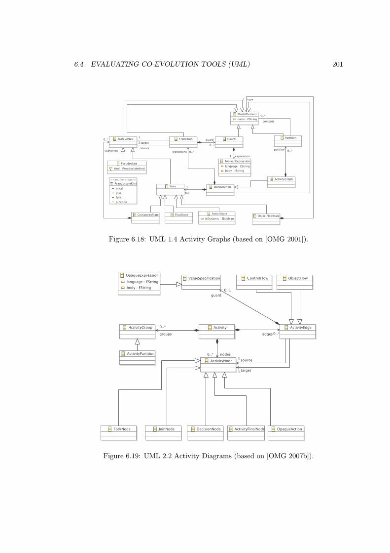
6.4. EVALUATING CO-EVOLUTION TOOLS (UML) 201
Figure 6.18: UML 1.4 Activity Graphs (based on [OMG 2001]).
Figure 6.19: UML 2.2 Activity Diagrams (based on [OMG 2007b]).

202 CHAPTER 6. EVALUATION
• Correctness: Does the transformation produce a model equivalent to the mi-grated UML 2.2. model included in the case resources?
• Conciseness: How much code is required to specify the transformation? (Sprin-kle and Karsai propose that the amount of effort required to codify migrationshould be directly proportional to the number of changes between original andevolved metamodel [Sprinkle & Karsai 2004]).
• Clarity: How easy is it to read and understand the used transformation? (Forexample, is a well-known or standardised language?)
• Appropriateness: How much effort is required to adapt the tool in providing asolution?
• Tool maturity: To what extent can the tool be used by people other than thedeveloper?
• Reproducibility: Can the solution be reproduced on another machine?11
• Extensions: Which of the case extensions (described below) were implementedin the solution?
To further distinguish between solutions, three extensions to the core task were pro-posed. The first extension was added after the case was submitted, and was proposedby the workshop organisers and the solution authors. The second and third extensionwere included in the case by the author.
Extension 1: Alternative Object Flow State Migration Semantics
Following the submission of the case to the competition, discussion on the TTC fo-rums12 revealed an ambiguity in the UML 2.2 specification indicating that the migra-tion semantics for the ObjectFlowState UML 1.4 concept are not clear from the UML2.2 specification. The case was revised to incorporate both the original semantics (sug-gested by the author and described above) and an alternative semantics (suggested bya workshop participant via the TTC forums) for migrating ObjectFlowStates. Thealternative semantics are now described.
In the core task described above, instances of ObjectFlowState were migratedto instances of ObjectNode. Any instances of Transition that had an Obje-ctFlowState as their source or target were migrated to instances of ObjectFlow.Figure 6.20 shows an example application of this migration semantics. Structures suchas the one shown in Figure 6.20(a) are migrated to an equivalent structure shown in
11Participants were invited to install their tools and solutions on virtual machines, which wouldlater be made accessible via the workshop proceedings.
12http://planet-research20.org/ttc2010/index.php?option=com_community&view=groups&task=viewgroup&groupid=4&Itemid=150 (registration required)

6.4. EVALUATING CO-EVOLUTION TOOLS (UML) 203
Figure 6.20(b). The Transitions, t1 and t2, are migrated to instances of Obje-ctFlow. Likewise, the instance of ObjectFlowState, s2, is migrated to an instanceof ObjectNode.
(a) ObjectFlowState structure in UML 1.4
(b) Equivalent ObjectNode structure in UML 2.2
Figure 6.20: Migrating Actions for the Core Task
This extension considered an alternative migration semantics for ObjectFlow-State. For this extension, instances of ObjectFlowState (and any connected Tr-ansitions) were migrated to instances of ObjectFlow, as shown in Figure 6.21 inwhich the UML 2.2 ObjectFlow, f1, replaces t1, t2 and s2.
(a) ObjectFlowState structure in UML 1.4
(b) Equivalent ObjectFlow structure in UML 2.2
Figure 6.21: Migrating Actions for Extension 1

204 CHAPTER 6. EVALUATION
Extension 2: Concrete Syntax
The second extension relates to the appearance of activity diagrams. The UML spec-ifications provide no formally defined metamodel for the concrete syntax of UML di-agrams. However, some UML tools store diagrammatic information in a structuredmanner using XML or a modelling tool. For example, the Eclipse UML 2 tools13 storediagrams as GMF [Gronback 2009] diagram models.
Submissions were invited to explore the feasibility of migrating the concrete syntaxof the activity diagram shown in Figure 6.17 to the concrete syntax in their chosenUML 2 tool. To facilitate this, the case resources included an ArgoUML project14
containing the activity diagram shown in Figure 6.17.
Extension 3: XMI
The UML specifications [OMG 2001, OMG 2007b] indicate that UML models shouldbe stored using XMI. However, because XMI has evolved at the same time as UML,UML 1.4 tools most likely produce XMI of a different version to UML 2.2 tools. Forinstance, ArgoUML produces XMI 1.2 for UML 1.4 models, while the Eclipse UML2tools produce XMI 2.1 for UML 2.2.
As an extension to the core task, submissions were invited to consider how tomigrate a UML 1.4 model represented in XMI 1.x to a UML 2.1 model representedin XMI 2.x. To facilitate this, the UML 1.4 model shown in Figure 6.17 was madeavailable in XMI 1.2 as part of the case resources.
Following the submission of the case, Tom Morris, the project leader for ArgoEclipseand a committer on ArgoUML, encouraged solutions to consider the extension describedabove. ArgoUML cannot, at present, migrate models from UML 1 to UML 2. On theTTC forums, Morris stated that “We have nothing available to fill this hole currently,so any contributions would be hugely valuable. Not only would achieve academic fameand glory from the contest, but you’d get to see your code benefit users of one of theoldest (10+ yrs) open source UML modeling tools.” 15
6.4.2 Model Migration Solution in Epsilon Flock
This section describes a Flock solution for migrating UML activity diagrams in responseto the evolution described above. The solution was developed by the author, and, atthe workshop, compared with migration strategies written in other languages. Theworkshop participants and organisers rated each tool.
The Flock migration strategy was developed in an iterative and incremental manner,using the following process, starting with an empty migration strategy:
1. Execute Flock on the original model, producing a migrated model.13http://www.eclipse.org/modeling/mdt/?project=uml2tools14http://argouml.tigris.org/15http://www.planet-research20.org/ttc2010/index.php?option=com_
community&view=groups&task=viewdiscussion&groupid=4&topicid=20&Itemid=150(registration required)

6.4. EVALUATING CO-EVOLUTION TOOLS (UML) 205
2. Compare the migrated model with the reference model provided in the case re-sources.
3. Change the Flock migration strategy.
4. Repeat until the migrated and reference models were the same.
The remainder of this section presents the Flock solution in an incremental manner.The code listings in this section show only those rules relevant to the iteration beingdiscussed.
Actions, Transitions and Final States
Development of the migration strategy began by executing an empty Flock migrationstrategy on the original model. Because Flock automatically copies model elementsthat have not been affected by evolution, the resulting model contained Pseudost-ates and Transitions, but none of the ActionStates from the original model. InUML 2.2 activities, OpaqueActions replace ActionStates. Listing 6.11 shows theFlock code for changing ActionStates to corresponding OpaqueActions.
1 migrate ActionState to OpaqueAction
Listing 6.11: Migrating Actions
Next, similar rules were added to migrate instances of FinalState to instances ofActivityFinalNode and to migrate instances of Transition to ControlFlow,as shown in Listing 6.12.
1 migrate FinalState to ActivityFinalNode
2 migrate Transition to ControlFlow
Listing 6.12: Migrating FinalStates and Transitions
Pseudostates
Development continued by selecting further types of state that were not present in themigrated model, such as Pseudostatess, which are not used in UML 2.2 activities.Instead, UML 2.2 activities use specialised Nodes, such as InitialNode. Listing 6.13shows the Flock code used to change Pseudostates to corresponding Nodes.
1 migrate Pseudostate to InitialNode when: original.kind = Original!
PseudostateKind#initial
2 migrate Pseudostate to DecisionNode when: original.kind = Original!
PseudostateKind#junction
3 migrate Pseudostate to ForkNode when: original.kind = Original!PseudostateKind#
fork
4 migrate Pseudostate to JoinNode when: original.kind = Original!PseudostateKind#
join
Listing 6.13: Migrating Pseudostates

206 CHAPTER 6. EVALUATION
Activities
In UML 2.2, Activitys no longer inherit from state machines. As such, some of thefeatures defined by Activity have been renamed. Specifically, transitions hasbecome edges and partitions has become groups. Furthermore, the states (ornodes in UML 2.2 parlance) of an Activity are now contained in a feature callednodes, rather than in the subvertex feature of a composite state accessed via thetop feature of Activity. The Flock migration rule shown in Listing 6.14 capturedthese changes.
1 migrate ActivityGraph to Activity {
2 migrated.edge = original.transitions.equivalent();
3 migrated.group = original.partition.equivalent();
4 migrated.node = original.top.subvertex.equivalent();
5 }
Listing 6.14: Migrating ActivityGraphs
Note that the rule in Listing 6.14 used the built-in equivalent operation to findmigrated model elements from original model elements. As discussed in Section 5.4,the equivalent operation invokes other migration rules where necessary and cachesresults to improve performance.
Next, a similar rule for migrating Guards was added. In UML 1.4, the the guardfeature of Transition references a Guard, which in turn references an Expres-sion via its expression feature. In UML 2.2, the guard feature of Transitionreferences an OpaqueExpression directly. Listing 6.15 captures this in Flock.
1 migrate Guard to OpaqueExpression {
2 migrated.body.add(original.expression.body);
3 }
Listing 6.15: Migrating Guards
Partitions
In UML 1.4 activity diagrams, Partition specifies a single containment referencefor its contents. In UML 2.2 activity diagrams, partitions have been renamed toActivityPartitions and specify two containment features for their contents, edg-es and nodes. Listing 6.16 shows the rule used to migrate Partitions to Activi-tyPartitions in Flock. The body of the rule shown in Listing 6.16 uses the collectoperation to segregate the contents feature of the original model element into twoparts.
1 migrate Partition to ActivityPartition {
2 migrated.edges = original.contents.collect(e:Transition | e.equivalent());
3 migrated.nodes = original.contents.collect(n:StateVertex | n.equivalent());
4 }
Listing 6.16: Migrating Partitions

6.4. EVALUATING CO-EVOLUTION TOOLS (UML) 207
ObjectFlows
Finally, two rules were written for migrating model elements relating to object flows.In UML 1.4 activity diagrams, object flows are specified using ObjectFlowState, asubtype of StateVertex. In UML 2.2 activity diagrams, object flows are modelledusing a subtype of ObjectNode. In UML 2.2 flows that connect to and from Obje-ctNodes must be represented with ObjectFlows rather than ControlFlows.
Listing 6.17 shows the Flock rule used to migrate Transitions to ObjectFlows.The rule applies for Transitions whose source or target StateVertex is of typeObjectFlowState.
1 migrate ObjectFlowState to ActivityParameterNode
2
3 migrate Transition to ObjectFlow when: original.source.isTypeOf(ObjectFlowState)
or original.target.isTypeOf(ObjectFlowState)
Listing 6.17: Migrating ObjectFlows
In addition to the core task, the Flock solution also approached two of the threeextensions described in the case (Section 6.4.1). The solutions to the extensions arenow discussed.
Alternative ObjectFlowState Migration Semantics
The first extension required submissions to consider an alternative migration semanticsfor ObjectFlowState, in which a single ObjectFlow replaces each ObjectFl-owState and any connected Transitions.
Listing 6.18 shows the Flock source code used to migrate ObjectFlowStates(and connecting Transitions) to a single ObjectFlow. This rule was used insteadof the two rules defined in Listing 6.17. In the body of the rule shown in Listing 6.18,the source of the Transition is copied directly to the source of the ObjectFlow.The target of the ObjectFlow is set to the target of the first outgoing Transitionfrom the ObjectFlowState.
1 migrate Transition to ObjectFlow when: original.target.isTypeOf(ObjectFlowState)
{
2 migrated.source = original.source.equivalent();
3 migrated.target = original.target.outgoing.first.target.equivalent();
4 }
Listing 6.18: Migrating ObjectFlowStates to a single ObjectFlow
Because, in this alternative semantics, ObjectFlowStates are represented asedges rather than nodes, the partition migration rule was changed such that Obje-ctFlowStates were not copied to the nodes feature of Partitions. To filter outthe ObjectFlowStates, line 3 of Listing 6.16 was changed to include a reject state-ment, as shown on line 3 of Listing 6.19.
1 migrate Partition to ActivityPartition {
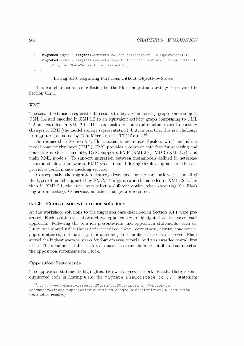
208 CHAPTER 6. EVALUATION
2 migrated.edges = original.contents.collect(e:Transition | e.equivalent());
3 migrated.nodes = original.contents.reject(ofs:ObjectFlowState | true).collect(n
:Original!StateVertex | n.equivalent());
4 }
Listing 6.19: Migrating Partitions without ObjectFlowStates
The complete source code listing for the Flock migration strategy is provided inSection C.2.1.
XMI
The second extension required submissions to migrate an activity graph conforming toUML 1.4 and encoded in XMI 1.2 to an equivalent activity graph conforming to UML2.2 and encoded in XMI 2.1. The core task did not require submissions to considerchanges to XMI (the model storage representation), but, in practice, this is a challengeto migration, as noted by Tom Morris on the TTC forums16.
As discussed in Section 5.4, Flock extends and reuses Epsilon, which includes amodel connectivity layer (EMC). EMC provides a common interface for accessing andpersisting models. Currently, EMC supports EMF (XMI 2.x), MDR (XMI 1.x), andplain XML models. To support migration between metamodels defined in heteroge-neous modelling frameworks, EMC was extended during the development of Flock toprovide a conformance checking service.
Consequently, the migration strategy developed for the core task works for all ofthe types of model supported by EMC. To migrate a model encoded in XMI 1.2 ratherthan in XMI 2.1, the user must select a different option when executing the Flockmigration strategy. Otherwise, no other changes are required.
6.4.3 Comparison with other solutions
At the workshop, solutions to the migration case described in Section 6.4.1 were pre-sented. Each solution was allocated two opponents who highlighted weaknesses of eachapproach. Following the solution presentations and opposition statements, each so-lution was scored using the criteria described above: correctness, clarity, conciseness,appropriateness, tool maturity, reproducibility and number of extensions solved. Flockscored the highest average marks for four of seven criteria, and was awarded overall firstprize. The remainder of this section discusses the scores in more detail, and summarisesthe opposition statements for Flock.
Opposition Statements
The opposition statements highlighted two weaknesses of Flock. Firstly, there is someduplicated code in Listing 6.13: the migrate Pseudostate to ... statement
16http://www.planet-research20.org/ttc2010/index.php?option=com_community&view=groups&task=viewdiscussion&groupid=4&topicid=20&Itemid=150(registration required)
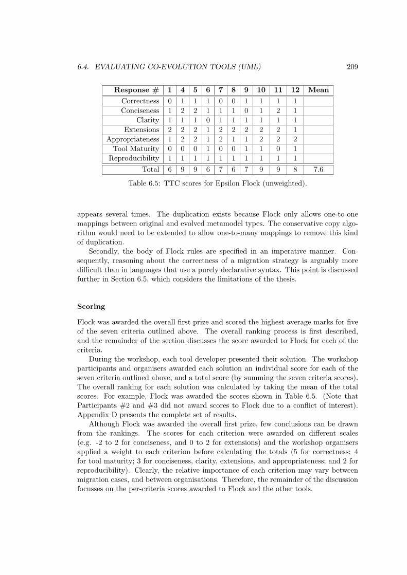
6.4. EVALUATING CO-EVOLUTION TOOLS (UML) 209
Response # 1 4 5 6 7 8 9 10 11 12 Mean
Correctness 0 1 1 1 0 0 1 1 1 1Conciseness 1 2 2 1 1 1 0 1 2 1
Clarity 1 1 1 0 1 1 1 1 1 1Extensions 2 2 2 1 2 2 2 2 2 1
Appropriateness 1 2 2 1 2 1 1 2 2 2Tool Maturity 0 0 0 1 0 0 1 1 0 1
Reproducibility 1 1 1 1 1 1 1 1 1 1Total 6 9 9 6 7 6 7 9 9 8 7.6
Table 6.5: TTC scores for Epsilon Flock (unweighted).
appears several times. The duplication exists because Flock only allows one-to-onemappings between original and evolved metamodel types. The conservative copy algo-rithm would need to be extended to allow one-to-many mappings to remove this kindof duplication.
Secondly, the body of Flock rules are specified in an imperative manner. Con-sequently, reasoning about the correctness of a migration strategy is arguably moredifficult than in languages that use a purely declarative syntax. This point is discussedfurther in Section 6.5, which considers the limitations of the thesis.
Scoring
Flock was awarded the overall first prize and scored the highest average marks for fiveof the seven criteria outlined above. The overall ranking process is first described,and the remainder of the section discusses the score awarded to Flock for each of thecriteria.
During the workshop, each tool developer presented their solution. The workshopparticipants and organisers awarded each solution an individual score for each of theseven criteria outlined above, and a total score (by summing the seven criteria scores).The overall ranking for each solution was calculated by taking the mean of the totalscores. For example, Flock was awarded the scores shown in Table 6.5. (Note thatParticipants #2 and #3 did not award scores to Flock due to a conflict of interest).Appendix D presents the complete set of results.
Although Flock was awarded the overall first prize, few conclusions can be drawnfrom the rankings. The scores for each criterion were awarded on different scales(e.g. -2 to 2 for conciseness, and 0 to 2 for extensions) and the workshop organisersapplied a weight to each criterion before calculating the totals (5 for correctness; 4for tool maturity; 3 for conciseness, clarity, extensions, and appropriateness; and 2 forreproducibility). Clearly, the relative importance of each criterion may vary betweenmigration cases, and between organisations. Therefore, the remainder of the discussionfocusses on the per-criteria scores awarded to Flock and the other tools.

210 CHAPTER 6. EVALUATION
Correctness Each tool developer demonstrated the extent to which their solutionperformed a correct migration of activity diagrams according to the migration semanticsdescribed in the case description (Section 6.4.1). The following scores could be awarded:-1 (probably doesn’t work at all), 0 (cannot judge), 1 (works for one model), and2 (works for more than one model). Flock received a mean score of 0.7, and wasranked seventh out of the nine solutions. Migration with Flock is specified with bothimperative and declarative language constructs, while many of the other solutions useonly declarative language constructs to specify the migration of UML activity diagramsand, hence, more could be said about the correctness of the solutions written in thoselanguages.
Conciseness Solutions were awarded one of the following scores for the concisenessof their migration strategies: -2 (very verbose), -1 (quite verbose), 0 (cannot judges),1 (quite concise), and 2 (very concise). Flock received a mean score of 1.2, and wasranked first out of the nine solutions. Three of the solutions used general purposelanguages (such as Java and Prolog), and these were ranked sixth, seventh and ninth.The other solutions used graph or model transformation languages, and, in general,scored more highly than those written in general-purpose languages.
Clarity The extent to which the intention of the migration could be determined fromthe migration strategy was scored on the following scale: -1 (no idea how it works), 0(some idea how it works), 1 (fully understand how it works). Flock received a meanscore of 0.9, was ranked first out of the nine solutions, and there was little variation inthe scores awarded to Flock (a score of 1 from eleven of the twelve responses, and a scoreof 0 from the remaining respondent). Tools tailored to model migration, such as Flockand COPE [Herrmannsdoerfer et al. 2009a], and graph transformation languages, suchas GrGen [Geiß & Kroll 2007] and MOLA [Kalnins et al. 2005], were ranked the highestin this category.
Appropriateness The suitability of the tool for migrating activity diagrams was as-sessed on the following scale: -2 (totally inappropriate), -1 (inappropriate), 0 (neutral),1 (somewhat appropriate), 2 (perfect fit). Flock received a mean score of 1.6, andwas ranked first out of the nine solutions. Again, tools tailored to model migration,such as Flock and COPE [Herrmannsdoerfer et al. 2009a], and graph transformationlanguages, such as GrGen [Geiß & Kroll 2007] and MOLA [Kalnins et al. 2005], wereranked the highest in this category.
Tool maturity The maturity of each tool was discussed during the solution presen-tations, and the workshop participants were able to use eight of the nine solutions viaa virtual machine. Scores were awarded on the following scale: -1 (prototype), 0 (av-erage), 1 (good). Flock received a mean score of 0.4, and was ranked third out of thenine solutions. Fujaba [Nickel et al. 2000] and GrGen [Geiß & Kroll 2007] were ranked

6.4. EVALUATING CO-EVOLUTION TOOLS (UML) 211
first and second in this category, and are established transformation tools that werefirst reported in the literature in 2000 and 2007 respectively.
Reproducibility Each developer was invited to configure a virtual machine withtheir tool and solution, and the workshop participants were invited to use each of thetools. A score of 1 was awarded if a working virtual machine image was provided bythe tool developer, and 0 otherwise. Flock had a mean score of 1, and ranked joint firstalong with seven of the other tools. The virtual machine image for one of the tools didnot work, and it was awarded a mean score of 0.
Extensions Three extensions to the core task were described in Section 6.4.1, and apoint was awarded for approaching each additional task. Flock was awarded a meanscore of 5.4, and ranked first of the nine solutions. Determining the extensions ap-proached by a solution seems to be an objective task, but some tools were awardeddifferent scores for the extensions criterion which is difficult to explain. For instance,the Flock solution (Section 6.4.2) approached two of the three extensions, but someof the participants awarded Flock only 1 point. Rather than analysing the scores, itis perhaps more interesting to note that the Flock solution was the only solution toapproach the XMI extension, and similarly for Fujaba [Nickel et al. 2000] and the con-crete syntax extension. This might indicate that contemporary migration tools canbe used to manage realistic metamodel changes, but lack some features that wouldbe desirable in an industrial setting (namely, interoperability with several modellingtechnologies and co-migration of abstract and concrete syntax).
6.4.4 Summary
This section has discussed the way in which Flock was evaluated by participating inthe 2010 edition of the Transformation Tools Contest (TTC). Flock was assessed byapplication to an example of migration from the UML and comparison with eight othermodel and graph transformation tools. Flock was awarded the overall first prize andranked first in five of seven categories by the workshop participants and organisers.
In addition to evaluating Flock, the work described in this section provides threefurther contributions. Firstly, the migration case submitted to TTC 2010, described inSection 6.4.1 provides a real-world example of co-evolution for use in future comparisonsof model migration tools. The case is based on the evolution of UML, between versions1.4 and 2.2. The migration strategy was devised by analysis of the UML specification,and by discussion between workshop participants.
Secondly, the Flock solution to the migration case (Section 6.4.2) demonstrates theway in which a migration strategy can be constructed using Flock. In particular, Sec-tion 6.4.2 describes an iterative and incremental development process and indicates thatan empty Flock migration strategy can provide a useful starting point for development.
Finally, Section 5.4 claims that Flock supports several modelling technologies. Thesolution described in Section 6.4.2 demonstrates the way in which Flock can be used

212 CHAPTER 6. EVALUATION
to migrate models over two modelling technologies: MDR (XMI 1.x) and EMF (XMI2.x), and hence supports the claim made in Section 5.4.
6.5 Limitations of the Proposed Structures andProcesses
The limitations of the research presented in the thesis are now discussed. Some of theshortcomings identified here are elaborated on in Section 7.2, which highlights areas offuture work.
Generality The thesis research focuses on model-metamodel co-evolution, but, asdiscussed in Chapter 4, metamodel changes can affect artefacts other than models.Model management operations and model editors are specified using metamodel con-cepts and, consequently, are affected when a metamodel changes. The work presentedin Chapter 5 focuses on migrating models in response to metamodel changes, anddoes not consider integration with tools for migrating model management operationsand model editors. To reduce the effort required to manage the effects of metamodelchanges, it seems reasonable to envisage a unified approach that migrates models, modelmanagement operations, model editors, and other affected artefacts.
Reproducibility The analysis and evaluation presented in Chapters 4 and 6 respec-tively involved using migration tools to understand and assess their functionality. Withthe exceptions noted below, the work presented in these chapters is difficult to repro-duce and therefore the results drawn are somewhat subjective. On the other hand,multiple approaches to analysis and evaluation have been taken, and the work hasbeen published and subjected to peer review.
Not all of the work in Chapter 4 and 6 is difficult to reproduce. In particular,the evaluation methods used in Chapter 6 are described in detail and a complete set ofresults are provided in Appendices C and D. In general, the lack of real-world examplesof co-evolution restricts the extent to which any work in this area can be consideredreproducible.
Formal semantics No formal semantics for the conservative copy algorithm (Sec-tion 5.4) have been provided. Instead, a reference implementation, Epsilon Flock,was developed, which facilitated comparison with other migration and transformationtools. Without a reference implementation, the evaluation described in Sections 6.2,6.3 and 6.4 would have been impossible. For Epsilon as a whole, a similar case has beenmade in favour of a reference implementation over a formal semantics [Kolovos 2009].For domains where completeness and correctness are a primary concern, a formal se-mantics would be required before Flock could be applied to manage model-metamodelco-evolution.
6.6. CHAPTER SUMMARY 213
6.6 Chapter Summary
The work presented in this chapter assessed the structures and processes proposedin Chapter 5. The evaluation has investigated the extent to which the prototypicalimplementations of the structures and processes increase developer productivity forco-evolution. Factors that affect the efficacy of the proposed structures and processeswere identified via the evaluation, and are summarised below. A range of techniqueswere used for evaluation, and the work presented in this chapter provides a foundationfor future work on – and further evaluation of – structures and processes for managingand identifying model-metamodel co-evolution.
Section 6.1 explored and compared the ways in which user-driven co-evolution isperformed with and without two of the structures proposed in Chapter 5. The com-parison suggested that the way in which models are represented and the way in whichconformance is checked affects developer productivity. A model representation thatis optimised for human rather than machine use might reduce the likelihood of mis-takes, particularly if the developers performing co-evolution lack expertise in manip-ulating XMI (the canonical model storage representation used by contemporary mod-elling frameworks). Checking conformance as the model is migrated might preventerrors, particularly if several types of breaking metamodel change are to be resolved,but might be a waste of computational resources when few breaking metamodel changesare to be resolved.
Section 6.2 investigated the conciseness of model migration strategies written us-ing new-target, existing-target and conservative copy source-target relationships. Theresults indicate that conservative copy yields the most concise model migration strate-gies, which might lead to increased developer productivity when specifying migrationmanually. However, other factors that were not assessed in this chapter will affect pro-ductivity, such as the learnability of the three source-target relationships. When spec-ifying migration with an operator-based or an inference approach, migration strategiesare typically presented to the user to facilitate selection between feasible alternatives.Further evaluation is needed to assess whether conciseness of migration strategies is adesirable quality for operator-based and inference approaches.
Sections 6.3 and 6.4 assessed Epsilon Flock (Section 5.4), a model-to-model trans-formation language tailored for model migration, by comparison with developer-drivenco-evolution tools and model-to-model transformation languages. The comparisons il-luminated various considerations for co-evolution. For example, the requirements andmaturity of the MDE process can preclude the use of some co-evolution approaches.When an established MDE process is used to develop a system, it might be impossi-ble to use co-evolution approaches that mandate specific tools or techniques, such asoperator-based approaches, which require that evolution is expressed with a specialisedmetamodel editor.
In addition to the evaluation described in this chapter, the work presented in thisthesis has been subject to peer review by the academic and Eclipse communities. Thethesis research has been published in 3 workshop papers, 2 European conference papersand 4 international conferences papers. Epsilon HUTN and Epsilon Flock (Chapter 5)

214 CHAPTER 6. EVALUATION
were contributed to the Epsilon project, a component of the research incubator for theEclipse Modeling Project (EMP), which is arguably the most active MDE communityat present. EMP’s research incubator hosts a limited number of participants, selectedthrough a rigorous process and contributions made to the incubator undergo regulartechnical review.
Evaluation of the research hypothesis has highlighted areas in which the structuresand processes proposed in Chapter 5 should be improved, and has motivated plans forfuture work, which are described in Section 7.2. Additionally, the work presented inthis chapter has identified areas in which further evaluation might be carried out. Inparticular, comprehensive user studies are needed to assess the usability and learnabilityof co-evolution tools, and to further evidence the benefits of co-evolution tools in termsof increased developer productivity.

Chapter 7
Conclusions
This thesis has investigated software evolution – a key and costly development activ-ity in software engineering [Moad 1990] – in the context of Model-Driven Engineering(MDE), a state-of-the art approach to software engineering. While MDE promisesincreased developer productivity [Watson 2008] and increased portability of softwaresystems [Frankel 2002], it also poses several challenges that threaten its adoption. Forexample, identifying and managing evolutionary change in the context of MDE presentsmany open research challenges [Mens & Demeyer 2007]. The thesis research has con-tributed to these research challenges and has explored the following research hypothesis:
In existing MDE projects, the evolution of MDE development artefacts istypically managed in an ad-hoc manner with little regard for re-use. Ded-icated structures and processes for managing evolutionary change can bedesigned by analysing evolution in existing MDE projects. Furthermore,supporting those dedicated structures and processes in contemporary MDEenvironments is beneficial in terms of increased productivity for software de-velopment activities pertaining to the management of evolutionary change.
To explore the thesis hypothesis, the following research objectives were defined.
1. Identify and analyse the evolution of MDE development artefacts in existingprojects.
2. Investigate the extent to which existing structures and processes can be used tomanage the evolution of MDE development artefacts.
3. Propose and develop new structures and processes for managing the evolution ofMDE development artefacts, and integrate those structures and processes with acontemporary MDE development environment.
4. Evaluate the proposed structures and processes for managing evolutionary change,particularly with respect to productivity.
215

216 CHAPTER 7. CONCLUSIONS
The remainder of this chapter summarises the contributions of the thesis in relationto the thesis hypothesis and research objectives, and gives a brief description of andmotivation for several potential extensions to the thesis research.
7.1 Contributions of the Thesis Research
The primary contributions of the thesis are summarised below, and the remainder ofthis section discusses each contribution in turn.
• Chapter 4 presented an analysis of evolution in existing MDE projects, whichindicated ways in which models, metamodels and model management operationsevolve, highlighted model-metamodel co-evolution as a commonly-occuring soft-ware evolution activity in MDE projects and led to a categorisation of existingapproaches to managing model-metamodel co-evolution.
• Chapter 5 described the design and implementation of structures and processes forperforming model-metamodel co-evolution, which included a metamodel-indepen-dent syntax for managing non-conformant models, a textual modelling notationfor manually migrating models, and a model-to-model transformation languagetailored for migration. The proposed structures and processes are interoperablewith EMF (Section 2.3.1), arguably the most widely-used contemporary MDEmodelling framework.
• Chapter 6 detailed the evaluation of the proposed structures and processes usingquantitive measurements, expert evaluation and application to large, independentexamples of co-evolution and explored the extent to which the proposed structuresand processes are beneficial in terms of increased developer productivity.
7.1.1 Investigation of Evolution in MDE Projects
The way in which evolution occurs and is managed in existing MDE projects wasanalysed in Chapter 4. The analysis investigated two types of evolutionary change,model-metamodel co-evolution and model synchronisation, which were identified fromthe review presented in Chapter 3. For the MDE projects considered in Chapter 4,several suitable model-metamodel co-evolution examples – and no suitable model syn-chronisation examples – were located, and consequently the remainder of the thesisfocused on model-metamodel co-evolution.
The co-evolution examples were used to identify the differences between existingapproaches to managing model-metamodel co-evolution, and to investigate the wayin which model-metamodel co-evolution is managed in existing MDE projects. Theinvestigation led to the definition of two distinct approaches to managing model-metamodel co-evolution in MDE projects, user-driven and developer-driven and toa categorisation of existing approaches, which was published in [Rose et al. 2009b] andhas since been used and extended in several papers, including [Jurack & Mantz 2010,Mendez et al. 2010].

7.1. CONTRIBUTIONS OF THE THESIS RESEARCH 217
7.1.2 Structures and Processes for Managing Co-evolution
The analysis of existing MDE projects presented in Chapter 4 highlighted challengesfor identifying and managing co-evolution. Managing co-evolution in a user-drivenmanner, for instance, is particularly challenging in contemporary MDE modelling en-vironments because conformance is enforced implicitly and models and metamodelsare kept separate. Similarly, the variation in programming and transformation lan-guages typically used to specify model migration presents a challenge for comparingexisting approaches to developer-driven co-evolution approaches. Moreover, none ofthe languages typically used have been tailored for the specific requirements of modelmigration. This thesis contributes structures and processes that seek to address thechallenges summarised above.
Metamodel-Indepenent Syntax
Contemporary MDE modelling frameworks cannot be used to load non-conformantmodels. Consequently, model migration cannot be performed using the structures typ-ically available in contemporary MDE modelling environments, such as model editorsand model management operations. The metamodel-independent syntax, introduced inChapter 5, is a proposed extension to contemporary MDE modelling frameworks thatfacilitates the loading of non-conformant models and provides services for reportingconformance problems.
The metamodel-independent syntax underpins the implementation of two furtherstructures, the textual modelling notation described below, and the automatic confor-mance checking service of Concordance [Rose et al. 2010c].
Textual Modelling Notation
When a small number of models are to be migrated, the effort required to specifyan executable migration strategy might not be justifiable. Instead, models can bemigrated by editing models by hand. The textual modelling notation, presented inChapter 5, provides a notation for editing models in contemporary MDE developmentenvironments. The notation proposed in this thesis adopts the Human-Usable TextualNotation (HUTN) [OMG 2004], a standard notation for textual modelling proposed bythe Object Management Group (OMG)1. The implementation of HUTN introduced inSection 5.2, Epsilon HUTN, is the sole reference implementation of the HUTN standard,and was published in [Rose et al. 2008a].
During user-driven co-evolution, model editors cannot be used for migration andediting models in their underlying storage representation, which will not have been op-timised for human use, can be error-prone and time consuming. The textual modellingnotation introduced in Chapter 5, Epsilon HUTN, provides an alternative to editingmodels in their underlying storage representation.
1http://www.omg.org

218 CHAPTER 7. CONCLUSIONS
A Process for User-Driven Co-evolution
The analysis of existing MDE projects highlighted several projects in which model mi-gration was performed using user-driven co-evolution techniques, and yet no existingwork sought to address the specific requirements of user-driven co-evolution. Con-temporary MDE modelling environments typically enforce conformance in an implicitmanner, and cannot be used to load non-conformant models. Consequently, user-drivenco-evolution is an iterative, error-prone and time-consuming task, because model edi-tors and model management operations cannot be used to assist migration.
A typical process for performing user-driven co-evolution involves performing modelmigration by repeatedly switching between a model editor (which reports conformanceproblems) a text editor (in which conformance is reconciled by the user). Chapter 6 pro-poses an alternative process in which conformance reporting and reconciliation occur inthe same environment, using the metamodel-independent syntax and textual modellingnotation described above. The alternative process was published in [Rose et al. 2009a].
Epsilon Flock: A Model Migration Language
In addition to the structures and processes for performing user-driven co-evolution, thethesis also contributes a structure dedicated to developer-driven co-evolution, a modelmigration language termed Epsilon Flock. The analysis performed in Chapter 4 showedthat model migration is often specified with a model-to-model transformation languageor with a general purpose programming language, and that these languages are nottailored to the specific requirements of model migration. The investigation presentedin Chapter 5, highlighted that a language tailored for model migration might provideseveral benefits over repurposing an existing language to specify model migration. Flockwas designed and implemented to explore the extent to which a language tailored formodel migration might increase developer productivity. The investigation of languagesfor model migration and the design and implementation of Flock were published in[Rose et al. 2010f].
Flock contributes a novel mechanism for relating source and target model elementstermed conservative copy, which is a hybrid of the two existing mechanisms used to re-late source and target model elements in contemporary model-to-model transformationlanguages. Conservative copy automatically copies to the target model every sourcemodel element that conforms to the target metamodel, and does not copy to the targetmodel source model elements that do not conform to the target metamodel.
7.1.3 Evaluation of Structures and Processes
The structures and processes introduced in this thesis have been evaluated using avariety of techniques, including a quantitive comparison, an expert evaluation andcomparison to related processes and structures. Existing work on evolutionary changein MDE has typically been evaluated with a case study (such as in [Sprinkle 2003])or by demonstration (such as in [Cicchetti 2008]), and few papers in the area reportthe strengths and weaknesses of proposed approaches, or seek to contextualise their
7.2. FUTURE WORK 219
contentions. The evaluation presented in Chapter 6 is a contribution in its own rightas it presents several alternative evaluation techniques, including the first expert eval-uation of model migration tools, and seeks to identify situations in which the proposedstructures and processes are both effective and ineffective.
7.2 Future Work
In the context of a doctoral thesis, it is impossible to thoroughly investigate many ofthe issues raised in exploring the thesis hypothesis. Below, several potential extensionsto the research presented in this thesis are identified, and any initial work in thoseareas is described.
7.2.1 Further Evaluation
The extent to which the structures and processes introduced in Chapter 5 increasedeveloper productivity for co-evolution has been explored via expert evaluation andcomparison to related work. Assessing the way in which the proposed structures andprocesses affect productivity is challenging due to the number of factors that affectproductivity. In practice, for example, the proposed structures and processes wouldbe used by developers with different expertise, and together with other tools and tech-niques. Evaluating the way in which software evolution is identified and managed inpractice using comprehensive case and user studies would be likely to allow strongerclaims to be made about the efficacy of the proposed structures and processes. Giventhe time constraints of a doctoral thesis, comprehensive case and user studies were notfeasible, and hence are desirable extensions to the thesis research. A key first stepwould be to establish a common vocabulary for discussing software evolution activitiesin the context of MDE, which would facilitate the comparison of user experiences.
7.2.2 Extensions to the Model Migration Language
The model migration language proposed and implemented in Chapter 5, Epsilon Flock,makes idiomatic commonly occurring patterns of model migration. The evaluationpresented in Chapter 6 suggested that migration strategies are often more concisewhen specified with Flock rather than when specified with contemporary model-to-model transformation languages. The evaluation also highlighted a limitation in theimplementation of Flock and demonstrated further patterns that might be captured bymodel migration languages.
Addressing these issues would further improve the conciseness and re-usability ofmodel migration strategies written in Flock and, hence, is an obvious area of futurework. In particular, one language construct controls two concerns in the current im-plementation of Flock, and introducing separate language constructs for each concerncould increase the potential for re-use between model migration rules. Applying Flockto the co-evolution examples used for evaluation highlighted further model migrationpatterns that might be made idiomatic in the language. For example, in situations

220 CHAPTER 7. CONCLUSIONS
where conservative copy can have side-effects, it may be desirable to afford more con-trol of the copying algorithm via, for example, an ignore keyword that identifiesvalues that should not be automatically copied.
7.2.3 Unifying Co-evolution Approaches
The thesis research has focused on one type of software evolution, model-metamodelco-evolution. Many further types of evolution occur in practice, including model refac-toring and model synchronisation, which were discussed in Chapter 3. Changes toa metamodel affect not only models but also model management operations, such asmodel transformations. When changes are propagated from a metamodel to a modelduring migration, further artefacts might be impacted as an indirect consequence ofthe metamodel evolution.
The use of distinct structures and processes for each type of evolution poses us-ability challenges relating to the interoperability of tools and increased training ef-fort. Seeking, instead, a unified approach to managing evolution might address thesechallenges, and presents an interesting opportunity for future work. Integrating thethesis research with approaches for managing other types of co-evolution, such astransformation-metamodel co-evolution, is one way in which the formulation of a uni-fied approach might proceed. To this end, an outline for integrating model-metamodeland transformation-metamodel co-evolution approaches has proposed in collaborationwith Anne Etien, an Associate Professor at the Universite Lille, and published in[Rose et al. 2010a].
7.2.4 Higher-Order Migration
In model transformation, a higher-order transformation consumes or produces a modeltransformation. Higher-order transformation has been used to generate model migra-tion strategies [Cicchetti 2008, Garces et al. 2009], and to compose and analyse trans-formations [Tisi et al. 2009]. Similarly, higher-order migration might be used effectivelyfor migrating model transformation specifications between similar model transforma-tion languages, and for migrating model management operations in response to changesto their specification language. For example, higher-order migration might be appliedto migrate model migration strategies between different types of transformation lan-guage, such as from a new-target to a conservative copy language.
7.2.5 Genericity
Chapter 6 identified a lack of metamodel-independent re-use as one of the primary weak-nesses of Flock compared to related approaches. In Flock, model migration strategiesare specified in terms of metamodel concepts, and consequently, the extent to whichcode can be re-used across migration strategies is reduced. By mixing model manage-ment languages with ideas from generic programming, one way in which model manage-ment operations can be specified in a manner that is independent of their metamodelhas been identified [de Lara & Guerra 2010]. Applying these ideas to Flock would

7.3. CLOSING REMARKS 221
facilitate increased re-use across model migration strategies, and address a primaryweakness of Flock.
7.3 Closing Remarks
Building the systems demanded by society now and in the future will require newapproaches to software engineering [Selic 2003]. MDE is a state-of-the-art, principledapproach to software engineering, and promises many benefits particularly with re-spect to the portability and maintainability of software systems [Kleppe et al. 2003,Frankel 2002]. While MDE shows promise, its success is reliant on the availability ofmature and powerful tools. Such tools are beginning to emerge, but typically fail toaddress concerns that affect their applicability to the engineering of large and complexsoftware systems, such as scalability and the cost of systems evolution.
The work presented in this thesis has demonstrated a systematic method for iden-tifying challenges for software evolution in typical MDE processes, proposed structuresand processes for addressing those challenges, and evaluated the structures and pro-cesses by comparison to related work and by application to real-world examples ofevolution.

Appendix A
Code Listings
This appendix provides complete versions of the code listings discussed in this thesis.Specifically, this appendix presents listings for migrating Petri nets with Ecore2Ecore(Section 5.3.2), and presents the model management operations used to implementEpsilon HUTN (Section 5.2).
A.1 Migrating Petri Nets with Ecore2Ecore
The code in Listings A.1 and A.2 demonstrates the way in which the Ecore2Ecore tool[Hussey & Paternostro 2006] can be used to perform model migration, using the Petrinets example described in Section 5.3.1.
1 package lit_petriNets.resources;
2
3 import java.io.InputStream;
4 import java.util.Collection;
5 import java.util.Iterator;
6 import java.util.LinkedList;
7 import java.util.Map;
8 import java.util.Map.Entry;
9
10 import lit_petriNets.Lit_petriNetsFactory;
11 import lit_petriNets.Lit_petriNetsPackage;
12 import lit_petriNets.PTArc;
13 import lit_petriNets.Place;
14 import lit_petriNets.TPArc;
15 import lit_petriNets.Transition;
16
17 import org.eclipse.emf.ecore.EObject;
18 import org.eclipse.emf.ecore.EStructuralFeature;
19 import org.eclipse.emf.ecore.resource.Resource;
223

224 APPENDIX A. CODE LISTINGS
20 import org.eclipse.emf.ecore.util.FeatureMap;
21 import org.eclipse.emf.ecore.xmi.XMLResource;
22 import org.eclipse.emf.ecore.xmi.impl.BasicResourceHandler;
23 import org.eclipse.emf.ecore.xml.type.AnyType;
24
25 public class PetriNetsResourceHandler extends BasicResourceHandler {
26
27 @Override
28 public void postLoad(XMLResource resource, InputStream inputStream,
Map<?, ?> options) {
29 final Map<EObject, AnyType> extMap = resource.
getEObjectToExtensionMap();
30
31 for(Entry<EObject, AnyType> entry : extMap.entrySet()) {
32 handleUnknownData(entry.getKey(), entry.getValue());
33 }
34 }
35
36 private void handleUnknownData(EObject eObj, AnyType unknownData) {
37 handleUnknownFeatures(eObj, unknownData.getMixed());
38 handleUnknownFeatures(eObj, unknownData.getAnyAttribute());
39 }
40
41 private void handleUnknownFeatures(EObject owner, FeatureMap
featureMap) {
42 for (Iterator<FeatureMap.Entry> iter = featureMap.iterator(); iter.
hasNext();) {
43 final FeatureMap.Entry entry = iter.next();
44
45 if (isTransition(owner)) {
46 if (isCollectionOfPlaces(entry.getValue(), owner.eResource())) {
47 final Transition transition = (Transition)owner;
48 final Collection<Place> places = toCollectionOfPlaces(entry.
getValue(), owner.eResource());
49
50 if (isSrc(entry.getEStructuralFeature())) {
51 migrateSrc(transition, places);
52
53 } else if (isDst(entry.getEStructuralFeature())) {
54 migrateDest(transition, places);
55 }
56

A.1. MIGRATING PETRI NETS WITH ECORE2ECORE 225
57 iter.remove();
58
59 } else {
60 System.err.println("Not a collection of places: " + entry.
getValue());
61 }
62 } else {
63 System.err.println("Not a transition: " + owner);
64 }
65 }
66 }
67
68 private boolean isTransition(EObject eObject) {
69 return Lit_petriNetsPackage.eINSTANCE.getTransition().isInstance(
eObject);
70 }
71
72 private boolean isSrc(EStructuralFeature feature) {
73 return "src".equals(feature.getName());
74 }
75
76 private boolean isDst(EStructuralFeature feature) {
77 return "dst".equals(feature.getName());
78 }
79
80 private boolean isCollectionOfPlaces(Object value, Resource resource)
{
81 final String[] uriFragments = ((String)value).split(" ");
82
83 for (String uriFragment : uriFragments) {
84 final EObject eObject = resource.getEObject(uriFragment);
85
86 if (eObject == null || !Lit_petriNetsPackage.eINSTANCE.getPlace().
isInstance(eObject))
87 return false;
88 }
89
90 return true;
91 }
92
93 private Collection<Place> toCollectionOfPlaces(Object value, Resource
resource) {
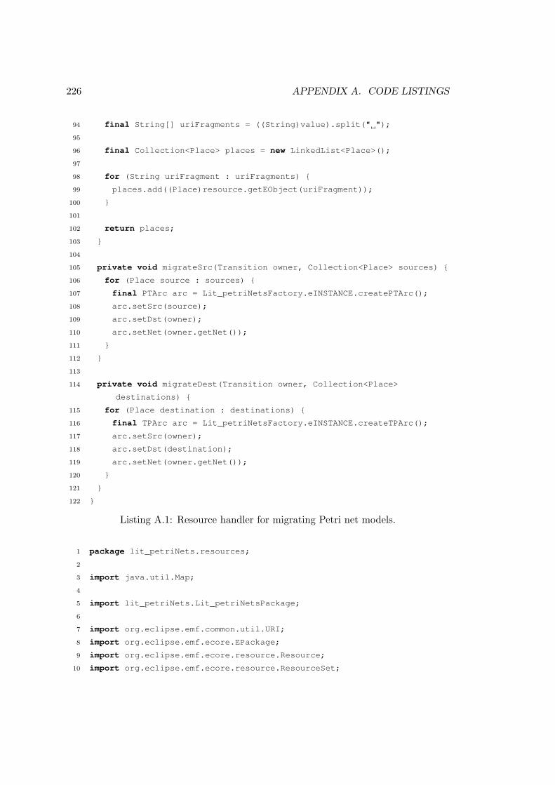
226 APPENDIX A. CODE LISTINGS
94 final String[] uriFragments = ((String)value).split(" ");
95
96 final Collection<Place> places = new LinkedList<Place>();
97
98 for (String uriFragment : uriFragments) {
99 places.add((Place)resource.getEObject(uriFragment));
100 }
101
102 return places;
103 }
104
105 private void migrateSrc(Transition owner, Collection<Place> sources) {
106 for (Place source : sources) {
107 final PTArc arc = Lit_petriNetsFactory.eINSTANCE.createPTArc();
108 arc.setSrc(source);
109 arc.setDst(owner);
110 arc.setNet(owner.getNet());
111 }
112 }
113
114 private void migrateDest(Transition owner, Collection<Place>
destinations) {
115 for (Place destination : destinations) {
116 final TPArc arc = Lit_petriNetsFactory.eINSTANCE.createTPArc();
117 arc.setSrc(owner);
118 arc.setDst(destination);
119 arc.setNet(owner.getNet());
120 }
121 }
122 }
Listing A.1: Resource handler for migrating Petri net models.
1 package lit_petriNets.resources;
2
3 import java.util.Map;
4
5 import lit_petriNets.Lit_petriNetsPackage;
6
7 import org.eclipse.emf.common.util.URI;
8 import org.eclipse.emf.ecore.EPackage;
9 import org.eclipse.emf.ecore.resource.Resource;
10 import org.eclipse.emf.ecore.resource.ResourceSet;

A.1. MIGRATING PETRI NETS WITH ECORE2ECORE 227
11 import org.eclipse.emf.ecore.resource.impl.ResourceSetImpl;
12 import org.eclipse.emf.ecore.util.EcoreUtil;
13 import org.eclipse.emf.ecore.util.ExtendedMetaData;
14 import org.eclipse.emf.ecore.xmi.XMIResource;
15 import org.eclipse.emf.ecore.xmi.XMLResource;
16 import org.eclipse.emf.ecore.xmi.impl.XMIResourceFactoryImpl;
17 import org.eclipse.emf.mapping.ecore2xml.Ecore2XMLPackage;
18 import org.eclipse.emf.mapping.ecore2xml.Ecore2XMLRegistry;
19 import org.eclipse.emf.mapping.ecore2xml.impl.Ecore2XMLRegistryImpl;
20 import org.eclipse.emf.mapping.ecore2xml.util.Ecore2XMLExtendedMetaData
;
21
22 public class PetriNetsFactoryImpl extends XMIResourceFactoryImpl {
23
24 public static final String BEFORE_NS_URI = "lit_petriNets";
25 public static final String AFTER_PLATFORM_URI = "platform:/plugin/
petrinets/model/After.ecore";
26 public static final String BEFORE_PLATFORM_URI = "platform:/plugin/
petrinets/model/Before_2_After.ecore2xml";
27
28 private ExtendedMetaData extendedMetaData;
29
30
31 public Resource createResource(URI uri) {
32 final XMIResource resource = (XMIResource) super.createResource(uri)
;
33
34 final Map<Object, Object> defaultLoadOptions = resource.
getDefaultLoadOptions();
35 defaultLoadOptions.put(XMLResource.OPTION_EXTENDED_META_DATA,
getExtendedMetaData());
36 defaultLoadOptions.put(XMLResource.OPTION_RECORD_UNKNOWN_FEATURE,
Boolean.TRUE);
37 defaultLoadOptions.put(XMLResource.OPTION_RESOURCE_HANDLER, new
PetriNetsResourceHandler());
38
39 return resource;
40 }
41
42 private ExtendedMetaData getExtendedMetaData() {
43 if(extendedMetaData == null) {
44 final ResourceSet resourceSet = new ResourceSetImpl();

228 APPENDIX A. CODE LISTINGS
45 final EPackage.Registry ePackageRegistry = resourceSet.
getPackageRegistry();
46
47 ePackageRegistry.put(BEFORE_NS_URI, Lit_petriNetsPackage.eINSTANCE)
;
48 ePackageRegistry.put(AFTER_PLATFORM_URI, Lit_petriNetsPackage.
eINSTANCE);
49
50 Ecore2XMLRegistry ecore2xmlRegistry = new Ecore2XMLRegistryImpl(
Ecore2XMLRegistry.INSTANCE);
51 ecore2xmlRegistry.put(BEFORE_NS_URI,
52 EcoreUtil.getObjectByType(
53 resourceSet.getResource(URI.createURI(BEFORE_PLATFORM_URI),
54 true).getContents(),
55 Ecore2XMLPackage.Literals.XML_MAP));
56
57 extendedMetaData = new Ecore2XMLExtendedMetaData(ePackageRegistry,
ecore2xmlRegistry);
58 }
59 return extendedMetaData;
60 }
61 }
Listing A.2: Resource factory for migrating Petri net models.
A.2 Model Management Operations for Epsilon HUTN
The code listings in this section demonstrate the way in which Epsilon HUTN (Sec-tion 5.2) is implemented, and are taken from Epsilon HUTN v0.8.0 (which was releasedin November 2010).
A.2.1 AST Model to Intermediate Model
The ETL transformation in Listing A.3 transforms a model that conforms to the ASTmetamodel (Figure 5.15) into a model that conforms to the metamodel-independentsyntax (Section 5.1).
1 pre {
2 var EmfTool := new Native(’org.eclipse.epsilon.emc.emf.tools.EmfTool’);
3
4 var ast := AntlrAst!Ast.allInstances().first();
5 var config := Config!Configuration.allInstances().first();
6
7 var spec := Intermediate!Spec.allInstances().first();

A.2. MODEL MANAGEMENT OPERATIONS FOR HUTN 229
8
9 for (root in ast.roots) {
10 if (AntlrAst!NameNode.isType(root) and root.text.toLowerCase() = ’@spec’) {
11 for (child in root.children) {
12
13 -- process @Spec.model package
14 if (child.text.toLowerCase() = ’model’) {
15 var modelFileAttribute := child.children.selectOne(n : AntlrAst!NameNode
| n.text = ’file’);
16
17 if (modelFileAttribute.isDefined()) {
18 var modelFileValue := modelFileAttribute.children.selectOne(t :
AntlrAst!TextualValueNode | true);
19
20 if (modelFileValue.isDefined()) {
21 spec.modelFile = modelFileValue.getValue();
22 }
23 }
24
25 -- process all other @Spec packages as metamodel specifications
26 } else {
27
28 for (grandchild in child.children.select(n : AntlrAst!NameNode | n.text.
toLowerCase() = ’nsuri’)) {
29 for (valueNode in grandchild.children.select(t : AntlrAst!
TextualValueNode | true)) {
30 var nsUri := new Intermediate!NsUri;
31 nsUri.value := valueNode.getValue();
32 nsUri.addTraceabilityInfo(valueNode.parent);
33 spec.nsUris.add(nsUri);
34 }
35 }
36 }
37 }
38 }
39 }
40 }
41
42 rule NameNode2PackageObject
43 transform n : AntlrAst!NameNode
44 to p : Intermediate!PackageObject {
45
46 guard : n.parent.isUndefined() and n.text.toLowerCase() <> ’@spec’
47
48 spec.objects.add(p);
49
50 p.type := n.text;
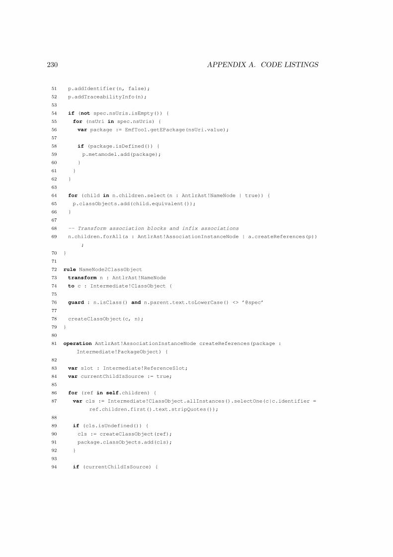
230 APPENDIX A. CODE LISTINGS
51 p.addIdentifier(n, false);
52 p.addTraceabilityInfo(n);
53
54 if (not spec.nsUris.isEmpty()) {
55 for (nsUri in spec.nsUris) {
56 var package := EmfTool.getEPackage(nsUri.value);
57
58 if (package.isDefined()) {
59 p.metamodel.add(package);
60 }
61 }
62 }
63
64 for (child in n.children.select(n : AntlrAst!NameNode | true)) {
65 p.classObjects.add(child.equivalent());
66 }
67
68 -- Transform association blocks and infix associations
69 n.children.forAll(a : AntlrAst!AssociationInstanceNode | a.createReferences(p))
;
70 }
71
72 rule NameNode2ClassObject
73 transform n : AntlrAst!NameNode
74 to c : Intermediate!ClassObject {
75
76 guard : n.isClass() and n.parent.text.toLowerCase() <> ’@spec’
77
78 createClassObject(c, n);
79 }
80
81 operation AntlrAst!AssociationInstanceNode createReferences(package :
Intermediate!PackageObject) {
82
83 var slot : Intermediate!ReferenceSlot;
84 var currentChildIsSource := true;
85
86 for (ref in self.children) {
87 var cls := Intermediate!ClassObject.allInstances().selectOne(c|c.identifier =
ref.children.first().text.stripQuotes());
88
89 if (cls.isUndefined()) {
90 cls := createClassObject(ref);
91 package.classObjects.add(cls);
92 }
93
94 if (currentChildIsSource) {

A.2. MODEL MANAGEMENT OPERATIONS FOR HUTN 231
95 slot := cls.slots.selectOne(r : Intermediate!ReferenceSlot | r.feature =
self.text);
96
97 if (slot.isUndefined()) {
98 slot := new Intermediate!ReferenceSlot;
99 slot.feature := self.text;
100 cls.slots.add(slot);
101 }
102
103 } else {
104 slot.values.add(cls.identifier);
105 }
106
107 currentChildIsSource := not currentChildIsSource;
108 }
109 }
110
111
112
113 operation AntlrAst!Node isClass() : Boolean {
114 if (self.parent.isUndefined()) {
115 return false;
116 } else {
117 return ast.roots.includes(self.parent);
118 }
119 }
120
121 operation Intermediate!ModelElement addTraceabilityInfo(node : AntlrAst!Node) :
Intermediate!ModelElement {
122 self.line := node.line;
123 self.col := node.column;
124 return self;
125 }
126
127 operation Intermediate!Object addIdentifier(node : AntlrAst!Node) {
128 self.addIdentifier(node, true);
129 }
130
131 operation Intermediate!Object addIdentifier(node : AntlrAst!Node, infer :
Boolean) {
132 var identifierNode : AntlrAst!Node := node.children.select(t : AntlrAst!
TextualValueNode | true).first();
133
134 if (identifierNode.isDefined()) {
135 self.identifier := identifierNode.text.stripQuotes();
136
137 } else if (infer) {

232 APPENDIX A. CODE LISTINGS
138 var nameSlot : Intermediate!AttributeSlot := self.slots.select(s:
Intermediate!AttributeSlot | s.feature = self.getIdentifierAttributeName
()).first();
139
140 if (nameSlot.isDefined() and nameSlot.values.size() = 1) {
141 self.identifier := nameSlot.values.first();
142 }
143 }
144 }
145
146 operation Intermediate!ClassObject inferAttributeValueFromIdentifier() {
147 if (self.identifier.isDefined() and self.getIdentifierAttributeName().isDefined
() and not self.slots.exists(s : Intermediate!AttributeSlot | s.feature =
self.getIdentifierAttributeName())) {
148 var slot := new Intermediate!AttributeSlot;
149 slot.feature := self.getIdentifierAttributeName();
150 slot.values.add(self.identifier);
151 self.slots.add(slot);
152 }
153 }
154
155 operation Intermediate!ClassObject getIdentifierAttributeName() : String {
156 var idRule : Config!IdentifierRule := config.rules.select(r : Config!
IdentifierRule | r.classifier = self.type).first();
157
158 if (config.isDefined() and idRule.isDefined()) {
159 return idRule.attribute;
160 }
161 }
162
163 operation Intermediate!ClassObject addDefaultValuesForAttributes() {
164 var classifierLevelAttributes := AntlrAst!ClassifierLevelAttributeNode.
allInstances().select(cla | cla.children.first().text = self.type).collect
(cla | cla.children.first());
165
166 for (cla in classifierLevelAttributes) {
167 var attribute := cla.children.first().text;
168 var defaultValues := cla.children.first().children.collect(node | node.text.
stripQuotes());
169
170 if (not self.slots.exists(s : Intermediate!AttributeSlot | s.feature =
attribute)) {
171 self.slots.add(createSlotFor(defaultValues, attribute).addTraceabilityInfo(
cla));
172 }
173 }
174

A.2. MODEL MANAGEMENT OPERATIONS FOR HUTN 233
175 var defaultValueRules := config.rules.select(r : Config!DefaultValueRule | r.
classifier = self.type);
176
177 for (defaultValueRule in defaultValueRules) {
178 if (not self.slots.exists(s : Intermediate!AttributeSlot | s.feature =
defaultValueRule.attribute)) {
179 self.slots.add(createSlotFor(defaultValueRule.defaultValue, defaultValueRule
.attribute));
180 }
181 }
182 }
183
184 -- Default Value Rules --
185 operation createSlotFor(defaultValue : String, attribute : String) :
Intermediate!Slot {
186 var defaultValues := new Sequence;
187 defaultValues.add(defaultValue);
188
189 return createSlotFor(defaultValues, attribute);
190 }
191
192 operation createSlotFor(defaultValues : Collection, attribute : String) :
Intermediate!Slot {
193 var slot : Intermediate!Slot := defaultValues.first().inferType().toSlot();
194
195 slot.feature := attribute;
196
197 defaultValues.forAll(value | slot.values.add(value.inferType()));
198
199 return slot;
200 }
201
202 operation String inferType() : Any {
203 -- Boolean?
204 if (self = ’true’) {
205 return true;
206
207 } else if (self = ’false’) {
208 return false;
209
210 -- Int?
211 } else if (self.isInteger()) {
212 return self.asInteger();
213
214 -- Real?
215 } else if (self.isReal()) {
216 return self.asFloat();

234 APPENDIX A. CODE LISTINGS
217
218 -- String
219 } else {
220 return self;
221 }
222 }
223
224 operation String stripQuotes() : String {
225 var result : String := self;
226
227 if (result.startsWith(’"’)) {
228 result := result.substring(1);
229 }
230
231 if (result.endsWith(’"’)) {
232 result := result.substring(0, result.length() - 1);
233 }
234
235 return result;
236 }
237
238 operation Intermediate!ClassObject addAdjective(a : AntlrAst!AdjectiveNode) {
239 var slot := new Intermediate!AttributeSlot;
240 slot.feature := a.getFeature();
241 slot.values.add(a.getValue());
242
243 slot.addTraceabilityInfo(a);
244
245 self.slots.add(slot);
246 }
247
248 operation AntlrAst!AdjectiveNode getFeature() : String {
249 if (self.text.startsWith(’˜’) or self.text.startsWith(’#’)) {
250 return self.text.substring(1);
251
252 } else {
253 return self.text;
254 }
255 }
256
257 operation AntlrAst!AdjectiveNode getValue() : Boolean {
258 return not self.text.startsWith(’˜’);
259 }
260
261 operation Intermediate!ClassObject addAttribute(n : AntlrAst!NameNode) {
262 var slot := self.findSlot(n.text);
263

A.2. MODEL MANAGEMENT OPERATIONS FOR HUTN 235
264 if (slot.isUndefined() or slot.isDifferentTypeTo(n.children.first().toSlot()))
{
265 slot := n.children.first().toSlot();
266 slot.feature := n.text;
267 }
268
269 if (Intermediate!ReferenceSlot.isType(slot)) {
270 for (valueNode in n.children) {
271 slot.values.add(valueNode.getValue());
272 }
273
274 } else {
275 for (valueNode in n.children) {
276 if (valueNode.text.isDefined()) {
277 slot.values.add(valueNode.getValue());
278 }
279 }
280 }
281
282 slot.addTraceabilityInfo(n);
283 self.slots.add(slot);
284 }
285
286 post {
287 Intermediate!AttributeSlot.all.forAll(s|s.coerceValues());
288 }
289
290 operation Intermediate!Slot isDifferentTypeTo(other : Intermediate!Slot) {
291 return self.eClass.name <> other.eClass.name;
292 }
293
294 -- Nulls --
295 operation AntlrAst!NullNode toSlot() : Intermediate!Slot {
296 return new Intermediate!AttributeSlot;
297 }
298
299 -- Booleans --
300 operation Boolean toSlot() : Intermediate!Slot {
301 return new Intermediate!AttributeSlot;
302 }
303
304 operation AntlrAst!TrueNode toSlot() : Intermediate!Slot {
305 return new Intermediate!AttributeSlot;
306 }
307
308 operation AntlrAst!TrueNode getValue() : Boolean {
309 return true;

236 APPENDIX A. CODE LISTINGS
310 }
311
312 operation AntlrAst!FalseNode toSlot() : Intermediate!Slot {
313 return new Intermediate!AttributeSlot;
314 }
315
316 operation AntlrAst!FalseNode getValue() : Boolean {
317 return false;
318 }
319
320 -- Strings --
321 operation String toSlot() : Intermediate!Slot {
322 return new Intermediate!AttributeSlot;
323 }
324
325 operation AntlrAst!TextualValueNode toSlot() : Intermediate!Slot {
326 return new Intermediate!AttributeSlot;
327 }
328
329 operation AntlrAst!TextualValueNode getValue() : String {
330 return self.text.stripQuotes();
331 }
332
333 -- Numbers --
334 operation Integer toSlot() : Intermediate!Slot {
335 return new Intermediate!AttributeSlot;
336 }
337
338 operation Real toSlot() : Intermediate!Slot {
339 return new Intermediate!AttributeSlot;
340 }
341
342 operation String isReal() : Boolean {
343 return ’.’.isSubstringOf(self);
344 }
345
346 operation AntlrAst!NumericValueNode toSlot() : Intermediate!Slot {
347 return new Intermediate!AttributeSlot;
348 }
349
350 operation AntlrAst!NumericValueNode getValue() : Any {
351 if (self.text.isReal()) {
352 return self.text.asDouble();
353 } else {
354 return self.text.asInteger();
355 }
356 }
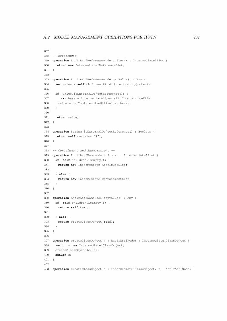
A.2. MODEL MANAGEMENT OPERATIONS FOR HUTN 237
357
358 -- References
359 operation AntlrAst!ReferenceNode toSlot() : Intermediate!Slot {
360 return new Intermediate!ReferenceSlot;
361 }
362
363 operation AntlrAst!ReferenceNode getValue() : Any {
364 var value = self.children.first().text.stripQuotes();
365
366 if (value.isExternalObjectReference()) {
367 var base = Intermediate!Spec.all.first.sourceFile;
368 value = EmfTool.resolveURI(value, base);
369 }
370
371 return value;
372 }
373
374 operation String isExternalObjectReference() : Boolean {
375 return self.contains("#");
376 }
377
378 -- Containment and Enumerations --
379 operation AntlrAst!NameNode toSlot() : Intermediate!Slot {
380 if (self.children.isEmpty()) {
381 return new Intermediate!AttributeSlot;
382
383 } else {
384 return new Intermediate!ContainmentSlot;
385 }
386 }
387
388 operation AntlrAst!NameNode getValue() : Any {
389 if (self.children.isEmpty()) {
390 return self.text;
391
392 } else {
393 return createClassObject(self);
394 }
395 }
396
397 operation createClassObject(n : AntlrAst!Node) : Intermediate!ClassObject {
398 var c := new Intermediate!ClassObject;
399 createClassObject(c, n);
400 return c;
401 }
402
403 operation createClassObject(c : Intermediate!ClassObject, n : AntlrAst!Node) {

238 APPENDIX A. CODE LISTINGS
404 c.type := n.text;
405 c.addTraceabilityInfo(n);
406
407 n.children.forAll(a : AntlrAst!AdjectiveNode | c.addAdjective(a));
408 n.children.forAll(n : AntlrAst!NameNode | c.addAttribute(n));
409
410 c.addIdentifier(n);
411 c.inferAttributeValueFromIdentifier();
412 c.addDefaultValuesForAttributes();
413 }
Listing A.3: Transforming AST models to intermediate models with ETL.
A.2.2 Intermediate Model Validation
The EVL constraints in Listing A.4 are executed on an intermediate model and atarget model, and produce a set of consistency problems. Listing A.4 includes thesyntactic constraints of HUTN (e.g. all identifiers must be unique) and the conformanceconstraints defined for the metamodel-independent syntax in Section 5.1.
1 pre {
2 var EmfTool := new Native(’org.eclipse.epsilon.emc.emf.tools.EmfTool’);
3 }
4
5 context Object {
6 constraint IdentifiersMustBeUnique {
7 guard: self.identifier.isDefined()
8 check: self.identifier.isUniqueIdentifier()
9 message: ’Duplicate identifier: ’ + self.identifier
10 }
11 }
12
13 context ClassObject {
14 constraint ClassifierMustExist {
15 guard: hasSpecificMetamodel()
16 check: self.hasEClass() or Metamodel!EClassifier.allInstances().select(c|c.
name = self.type).size() = 1
17 message: ’Unrecognised classifier: ’ + self.type
18 }
19
20 constraint ClassifierMustBeClass {
21 guard: self.satisfies(’ClassifierMustExist’)
22 check: self.hasEClass()
23 message: ’Cannot instantiate the enumeration or data type: ’ + self.type
24 }
25
26 constraint ClassMustNotBeAbstract {
27 guard: self.satisfies(’ClassifierMustBeClass’)

A.2. MODEL MANAGEMENT OPERATIONS FOR HUTN 239
28 check: not self.toClass().isAbstract()
29 message: ’Cannot instantiate the abstract class: ’ + self.type
30 }
31
32 constraint ClassMustSpecifyRequiredReferences {
33 guard: self.satisfies(’ClassMustNotBeAbstract’)
34 check: self.getAllReferencesThatRequireAValueButDontHaveOne().isEmpty()
35 message: self.identifier + ’ must specify a value for the following reference
features: ’ + self.getAllReferencesThatRequireAValueButDontHaveOne().
collect(f|f.name).toString()
36
37 fix {
38 title : ’Infer empty instances’
39 do {
40 for (reference in self.getAllReferencesThatRequireAValueButDontHaveOne())
{
41 -- An instance can be inferred if no values are required
42 if (reference.aValueCanBeInferred()) {
43 var instance := new Intermediate!ClassObject;
44 instance.type := reference.eType.name;
45
46 var slot := new Intermediate!ContainmentSlot;
47 slot.feature := reference.name;
48 slot.values.add(instance);
49
50 self.slots.add(slot);
51 }
52 }
53 }
54 }
55 }
56 }
57
58 context Slot {
59 constraint FeatureMustExist {
60 guard: hasSpecificMetamodel() and self.owner.isTypeOf(ClassObject) and self.
owner.toClass().isDefined() and self.feature.isDefined()
61 check: self.owner.toClass().eAllStructuralFeatures.select(c|c.name = self.
feature).size() = 1
62 message: ’Unrecognised feature: ’ + self.feature
63 }
64
65 constraint FeatureMustBeChangeable {
66 guard: self.satisfies(’FeatureMustExist’)
67 check: self.getEStructuralFeature().changeable
68 message: ’Feature ’ + self.getEStructuralFeature().name + ’ is not changeable
’

240 APPENDIX A. CODE LISTINGS
69 }
70
71 constraint MustBeTypeCompatibleWithFeature {
72 guard: self.satisfies(’FeatureMustExist’)
73 check: self.typeCompatibleWith(self.getEStructuralFeature())
74 message: ’Expected ’ + self.getEStructuralFeature().eType.name + ’ for: ’ +
self.feature
75 }
76
77 constraint SingleValuedFeatureCannotTakeMultipleValues {
78 guard: self.satisfies(’FeatureMustExist’)
79 check: self.getEStructuralFeature().isMany() or self.values.size = 1
80 message: ’Multiple values not permitted for: ’ + self.feature
81 }
82 }
83
84 context ReferenceSlot {
85 constraint FeatureMustBeReference {
86 guard: self.satisfies(’MustBeTypeCompatibleWithFeature’)
87 check: not self.getEStructuralFeature().isContainment
88 message: ’A reference value was specified for the containment feature ’ +
89 self.owner.type + ’#’ + self.feature + ’.’
90 }
91
92 constraint ReferencedIdentifiersMustExist {
93 guard: self.satisfies(’FeatureMustBeReference’)
94 check: self.values.forAll(i|i.isRecognisedIdentifier())
95 message: self.values.selectOne(i|not i.isRecognisedIdentifier()).getMessage()
96
97 }
98 }
99
100 context ContainmentSlot {
101 constraint FeatureMustBeContainment {
102 guard: self.satisfies(’MustBeTypeCompatibleWithFeature’)
103 check: self.getEStructuralFeature().isContainment
104 message: ’A contained object was specified for the non-containment feature ’
+
105 self.owner.type + ’#’ + self.feature + ’.’
106 }
107 }
108
109 operation hasSpecificMetamodel() : Boolean {
110 return Spec.allInstances().at(0).nsUris.notEmpty();
111 }
112
113 operation String isUniqueIdentifier() : Boolean {

A.2. MODEL MANAGEMENT OPERATIONS FOR HUTN 241
114 return ClassObject.allInstances().select(c|c.identifier = self).size() = 1;
115 }
116
117 operation String isRecognisedIdentifier() : Boolean {
118 if (’#’.isSubstringOf(self)) {
119 return self.canLocateExternalModel() and self.canLocateExternalModelElement()
;
120
121 } else {
122 return self.isUniqueIdentifier();
123 }
124 }
125
126 operation String getMessage() : String {
127 if (’#’.isSubstringOf(self)) {
128 if (not self.canLocateExternalModel()) {
129 return ’Model not found: ’ + self.split(’#’).first();
130 }
131
132 return ’Model element not found: ’ + self.split(’#’).last();
133
134 } else {
135 return ’Unrecognised identifier: ’ + self;
136 }
137 }
138
139 operation String canLocateExternalModel() : Boolean {
140 return EmfTool.resourceExists(self.split(’#’).first());
141 }
142
143 operation String canLocateExternalModelElement() : Boolean {
144 return EmfTool.modelElementExists(self);
145 }
146
147 operation String toClass() : Metamodel!EClass {
148 if (’#’.isSubstringOf(self)) {
149 -- External object reference, locate in external model
150
151 var object := EmfTool.getEObject(self);
152
153 if (object.isDefined()) {
154 return object.eClass();
155 }
156
157 } else {
158 -- Internal object reference, located in current model
159

242 APPENDIX A. CODE LISTINGS
160 var object := ClassObject.allInstances().selectOne(c|c.identifier = self);
161
162 if (object.isDefined()) {
163 return object.toClass();
164 }
165 }
166 }
167
168 operation ClassObject toClass() : Metamodel!EClass {
169 return self.getEClass();
170 }
171
172 operation Metamodel!EClass getAllClassObjects() : Collection(ClassObject) {
173 return ClassObject.all.select(c|c.hasEClass() and c.getEClass().name = self.
name);
174 }
175
176 operation Metamodel!EClass getAllFeaturesThatRequireAValue() : Sequence(
EReference) {
177 return self.eAllStructuralFeatures.select(f|f.lowerBound > 0 and f.changeable
and not f.transient);
178 }
179
180 operation Metamodel!EClass getAllReferencesThatRequireAValue() : Sequence(
EReference) {
181 return self.eAllReferences.select(f|f.lowerBound > 0 and f.changeable and not f
.transient);
182 }
183
184 operation Metamodel!EReference hasOppositeReferencing(classObject : ClassObject)
: Boolean {
185 if (self.eOpposite.isDefined()) {
186 for (class in self.eType.getAllClassObjects()) {
187 var slot := class.findSlot(self.eOpposite.name);
188
189 if (slot.isDefined()) {
190 if (slot.isKindOf(ReferenceSlot) and slot.values.includes(classObject.
identifier)) {
191 return true;
192
193 } else if (slot.classObjects.includes(classObject)) {
194 return true;
195 }
196
197 }
198 }
199 }

A.2. MODEL MANAGEMENT OPERATIONS FOR HUTN 243
200
201 return false;
202 }
203
204 operation ClassObject getAllReferencesThatRequireAValueButDontHaveOne() :
Sequence(EReference) {
205 return self.toClass().getAllReferencesThatRequireAValue().reject(r|self.slots
.exists(s|s.feature = r.name) or r.hasOppositeReferencing(self));
206 }
207
208 operation Metamodel!EReference aValueCanBeInferred() : Boolean {
209 return self.isContainment and self.eType.getAllFeaturesThatRequireAValue().
isEmpty();
210 }
211
212
213 operation Sequence toString() : String {
214 var result : String := ’’;
215
216 for (element in self) {
217 result := result + element.toString();
218 if (hasMore) { result := result + ’, ’; }
219 }
220
221 return result;
222 }
Listing A.4: Syntactic and Conformance Constraints in EVL.
A.2.3 Intermediate Model to Target Model
The EGL template in Listing A.5 is used to generate an ETL transformation betweenintermediate models and target models.
1 pre {
2 var EmfTool := new Native(’org.eclipse.epsilon.emc.emf.tools.EmfTool’);
3 }
4
5 [% if (not PackageObject.all.isEmpty()) { %]
6 [% for (class in getAllEClassesUsed()) { %]
7 rule Object2[%=class.name%]
8 transform o : Intermediate!ClassObject
9 to t : Model!‘[%=class.name%]‘ {
10
11 guard: o.type = ’[%=class.name%]’
12
13 [% for (attribute in class.eAllAttributes) { %]
14 if (o.findSlot(’[%=attribute.name%]’).isDefined()) {
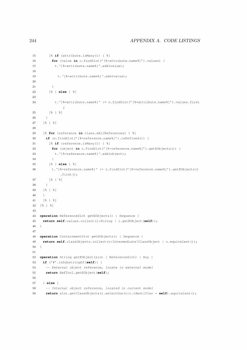
244 APPENDIX A. CODE LISTINGS
15 [% if (attribute.isMany()) { %]
16 for (value in o.findSlot(’[%=attribute.name%]’).values) {
17 t.‘[%=attribute.name%]‘.add(value);
18
19 t.‘[%=attribute.name%]‘.add(value);
20
21 }
22 [% } else { %]
23
24 t.‘[%=attribute.name%]‘ := o.findSlot(’[%=attribute.name%]’).values.first
;
25 [% } %]
26 }
27 [% } %]
28
29 [% for (reference in class.eAllReferences) { %]
30 if (o.findSlot(’[%=reference.name%]’).isDefined()) {
31 [% if (reference.isMany()) { %]
32 for (object in o.findSlot(’[%=reference.name%]’).getEObjects()) {
33 t.‘[%=reference.name%]‘.add(object);
34 }
35 [% } else { %]
36 t.‘[%=reference.name%]‘ := o.findSlot(’[%=reference.name%]’).getEObjects()
.first();
37 [% } %]
38 }
39 [% } %]
40 }
41 [% } %]
42 [% } %]
43
44 operation ReferenceSlot getEObjects() : Sequence {
45 return self.values.collect(i:String | i.getEObject(self));
46 }
47
48 operation ContainmentSlot getEObjects() : Sequence {
49 return self.classObjects.collect(o:Intermediate!ClassObject | o.equivalent());
50 }
51
52 operation String getEObject(slot : ReferenceSlot) : Any {
53 if (’#’.isSubstringOf(self)) {
54 -- External object reference, locate in external model
55 return EmfTool.getEObject(self);
56
57 } else {
58 -- Internal object reference, located in current model
59 return slot.getClassObjects().selectOne(c|c.identifier = self).equivalent();

A.2. MODEL MANAGEMENT OPERATIONS FOR HUTN 245
60 }
61 }
62
63
64 [%
65 operation getAllEClassesUsed() : Sequence {
66 var types := new Set;
67 var classes := new Sequence;
68
69 for (classObject in ClassObject.all) {
70 if (types.excludes(classObject.type)) {
71 types.add(classObject.type);
72 classes.add(classObject.getEClass());
73 }
74 }
75
76 return classes;
77 }
78 %]
Listing A.5: EGL template that generates an intermediate model to target model
transformation (in ETL)


Appendix B
A Graphical Editor forProcess-Oriented Programs
This appendix describes the design and implementation of a prototypical graphicaleditor for process-oriented programs. The work presented here was conducted in col-laboration with Adam Sampson, then a Research Associate at the University of Kent.The way in which the graphical editor changed throughout its development providedwas used for the evaluation presented in Section 6.1.
The purpose of the collaboration was to explore the suitability of MDE for designinga graphical notation and editor for programs written in process-oriented programminglanguages, such as occam-π [Welch & Barnes 2005]. The collaboration produced aprototypical graphical editor implemented with EMF and GMF (Section 2.3).
Process-oriented programs are specified in terms of three core concepts: processes,connection points and channels. Processes are the fundamental building blocks of aprocess-oriented program. Channels are the mechanism by which processes communi-cate, and are unidirectional. Connection points define the channels on which a processcan communicate. Connection points are used to specify the way in which a processcan communicate, and can optionally be bound to a channel. Because channels are uni-directional, connection points are either reading (consume messages from the channel)or writing (generate messages on the channel).
The graphical notation and editor were implemented in an iterative and incrementalmanner. The abstract syntax of the domain was specified as a metamodel, captured inEcore, which is the metamodelling language provided by EMF. The graphical concretesyntax was specified with GMF, using EuGENia [Kolovos et al. 2010]. EMF and GMFare described more thoroughly in Section 2.3.
The remainder of this appendix describes the six iterations that took place duringthe development of the graphical editor for process-oriented programs. Each sectiondescribes the goal of the iteration, the changes made to the metamodel to meet thegoal, and the impact of the changes on models that had been constructed in previousiterations. The way in which models were migrated with a user-driven co-evolutionapproach is also described.
247
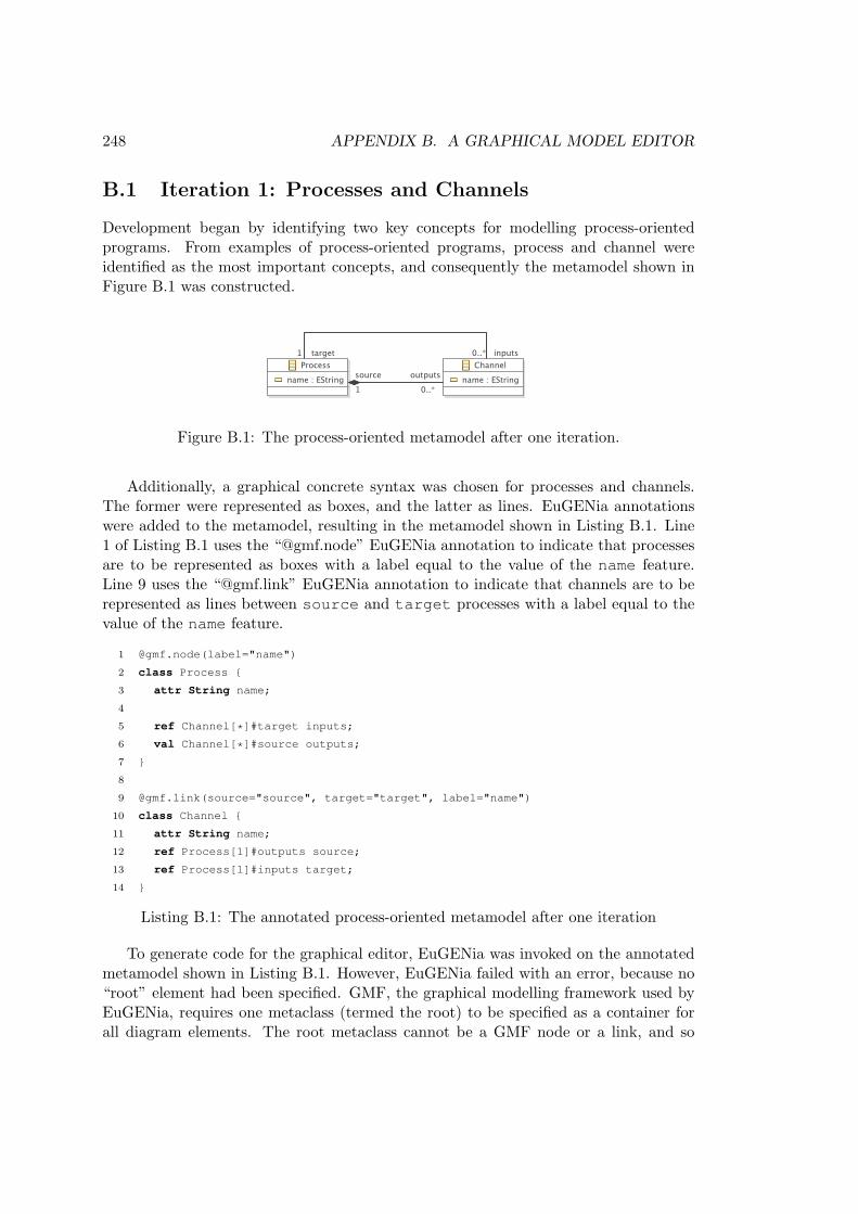
248 APPENDIX B. A GRAPHICAL MODEL EDITOR
B.1 Iteration 1: Processes and Channels
Development began by identifying two key concepts for modelling process-orientedprograms. From examples of process-oriented programs, process and channel wereidentified as the most important concepts, and consequently the metamodel shown inFigure B.1 was constructed.
Figure B.1: The process-oriented metamodel after one iteration.
Additionally, a graphical concrete syntax was chosen for processes and channels.The former were represented as boxes, and the latter as lines. EuGENia annotationswere added to the metamodel, resulting in the metamodel shown in Listing B.1. Line1 of Listing B.1 uses the “@gmf.node” EuGENia annotation to indicate that processesare to be represented as boxes with a label equal to the value of the name feature.Line 9 uses the “@gmf.link” EuGENia annotation to indicate that channels are to berepresented as lines between source and target processes with a label equal to thevalue of the name feature.
1 @gmf.node(label="name")
2 class Process {
3 attr String name;
4
5 ref Channel[*]#target inputs;
6 val Channel[*]#source outputs;
7 }
8
9 @gmf.link(source="source", target="target", label="name")
10 class Channel {
11 attr String name;
12 ref Process[1]#outputs source;
13 ref Process[1]#inputs target;
14 }
Listing B.1: The annotated process-oriented metamodel after one iteration
To generate code for the graphical editor, EuGENia was invoked on the annotatedmetamodel shown in Listing B.1. However, EuGENia failed with an error, because no“root” element had been specified. GMF, the graphical modelling framework used byEuGENia, requires one metaclass (termed the root) to be specified as a container forall diagram elements. The root metaclass cannot be a GMF node or a link, and so

B.2. ITERATION 2: INTEROPERABILITY WITH GMF 249
the second iteration involved adding an additional metaclass for interoperability withGMF.
B.2 Iteration 2: Interoperability with GMF
In the second iteration, an additional metaclass, Model, was added to the metamodel asshown in Figure B.2. The Model metaclass was used to provide GMF with a containerfor storing all of the diagram elements for each process-oriented diagram.
Figure B.2: The process-oriented metamodel after two iterations.
The Model metaclass was annotated with “@gmf.diagram” to indicate that itshould be used as the diagram’s root element (Listing B.2). Root elements do nothave a concrete syntax and do not appear in the graphical editor.
EuGENia was invoked on the annotated metamodel shown in Listing B.2 to producecode for the graphical editor. Figure B.3 shows a model that was constructed to testthe generated editor and comprised two processes, P1 and P2, and one channel, a.
B.3 Iteration 3: Shared Channels
In previous iterations, channels had been contained within their source process. Thenested structure made it more difficult to explore process-oriented models in EMF’stree editor due to the additional level of nesting. Consequently, the metamodel waschanged such that channels were contained in the root element, rather than in thesource process, resulting in the metamodel shown in Figure B.4.
No additional EuGENia annotations were added to the metamodel during thisiteration. In other words, the graphical notation (concrete syntax) was not changed,and the resulting editor was identical in appearance to the previous one. However,the EMF tree editor showed just one level of nesting (everything is contained insidemodel).
The existing models required migration because of the way in which XMI differen-tiates between reference and containment values. Each channel was moved to the newchannels reference of Model, and existing values in the outputs reference of Conn-

250 APPENDIX B. A GRAPHICAL MODEL EDITOR
Figure B.3: A diagram after the second iteration.
Figure B.4: The process-oriented metamodel after three iterations.

B.3. ITERATION 3: SHARED CHANNELS 251
1 @gmf.diagram
2 class Model {
3 val Process[*] processes;
4 }
5
6 @gmf.node(label="name")
7 class Process {
8 attr String name;
9
10 ref Channel[*]#target inputs;
11 val Channel[*]#source outputs;
12 }
13
14
15 @gmf.link(source="source", target="target", label="name")
16 class Channel {
17 attr String name;
18 ref Process[1]#outputs source;
19 ref Process[1]#inputs target;
20 }
Listing B.2: The annotated process-oriented metamodel after two iterations
ectionPoint were changed to a reference value. Figure B.5(a) shows the HUTN fora model prior to migration, and Figure B.5(b) shows the reconciled, migrated HUTN.

252 APPENDIX B. A GRAPHICAL MODEL EDITOR
(a) HUTN prior to migration
(b) HUTN after migration
Figure B.5: Migration between the second and third versions of the process-orientedmetamodel, with Epsilon HUTN (Section 5.2)
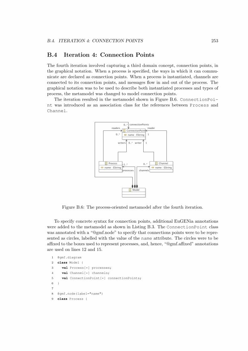
B.4. ITERATION 4: CONNECTION POINTS 253
B.4 Iteration 4: Connection Points
The fourth iteration involved capturing a third domain concept, connection points, inthe graphical notation. When a process is specified, the ways in which it can commu-nicate are declared as connection points. When a process is instantiated, channels areconnected to its connection points, and messages flow in and out of the process. Thegraphical notation was to be used to describe both instantiated processes and types ofprocess, the metamodel was changed to model connection points.
The iteration resulted in the metamodel shown in Figure B.6. ConnectionPoi-nt was introduced as an association class for the references between Process andChannel.
Figure B.6: The process-oriented metamodel after the fourth iteration.
To specify concrete syntax for connection points, additional EuGENia annotationswere added to the metamodel as shown in Listing B.3. The ConnectionPoint classwas annotated with a “@gmf.node” to specify that connections points were to be repre-sented as circles, labelled with the value of the name attribute. The circles were to beaffixed to the boxes used to represent processes, and, hence, “@gmf.affixed” annotationsare used on lines 12 and 15.
1 @gmf.diagram
2 class Model {
3 val Process[*] processes;
4 val Channel[*] channels;
5 val ConnectionPoint[*] connectionPoints;
6 }
7
8 @gmf.node(label="name")
9 class Process {

254 APPENDIX B. A GRAPHICAL MODEL EDITOR
10 attr String name;
11
12 @gmf.affixed
13 ref ConnectionPoint[*] readers;
14
15 @gmf.affixed
16 ref ConnectionPoint[*] writers;
17 }
18
19
20 @gmf.link(source="reader", target="writer", label="name", incoming="true")
21 class Channel {
22 attr String name;
23 ref ConnectionPoint[1] reader;
24 ref ConnectionPoint[1] writer;
25 }
26
27 @gmf.node(label="name", label.placement="external", label.icon="false", figure="
ellipse", size="15,15")
28 class ConnectionPoint {
29 attr String name;
30 }
Listing B.3: The annotated process-oriented metamodel after four iterations
A new version of the graphical editor was generated by invoking EuGENia on theannotated metamodel. A larger test model was constructed to test the editor, and isshown in Figure B.7. The existing models required migration because the inputs andoutputs references of Process and the source and target references of Channelhad been removed.
To migrate each existing model, two connection points were created for each channelin the model. The source and target reference of the channel was changed toreference the new connection points, as were the corresponding values of the readersand writers references of the relevant processes. Figure B.8(a) shows the HUTN fora model prior to migration, and Figure B.8(b) shows the reconciled, migrated HUTN.

B.4. ITERATION 4: CONNECTION POINTS 255
Figure B.7: A diagram after the fourth iteration.

256 APPENDIX B. A GRAPHICAL MODEL EDITOR
(a) HUTN prior to migration
(b) HUTN after migration
Figure B.8: Migration between the third and fourth versions of the process-orientedmetamodel, with Epsilon HUTN (Section 5.2)

B.5. ITERATION 5: CONNECTION POINT TYPES 257
B.5 Iteration 5: Connection Point Types
Channels are unidirectional, and so connection points are either reading or writing. Aprocess uses the former to consume messages from a channel, and the latter to producemessages on a channel. Testing the graphical editor produced in the fourth iterationshowed that it was not immediately obvious as to which connection points were readingand which were writing. The fifth iteration involved changing the graphical editor tobetter distinguish between reading and writing connection points.
The iteration resulted in the metamodel shown in Figure B.9. ConnectionPointwas made abstract, and two subclass, ReadingConnectionPoint and WritingCo-nnectionPoint, were introduced. The four references to ConnectionPoint werechanged to reference one of the two subclasses.
Figure B.9: The process-oriented metamodel after five iterations.
The graphical notation was changed, as shown in Listing B.4. The WritingCo-nnectionPoint class was annotated with an additional colour attribute to specifythat writing connection points were to be represented with a black circle. White is thedefault colour for a “@gmf.node” annotation, and so reading connection points wererepresented as white circles.
1 @gmf.diagram
2 class Model {

258 APPENDIX B. A GRAPHICAL MODEL EDITOR
3 val Process[*] processes;
4 val Channel[*] channels;
5 val ConnectionPoint[*] connectionPoints;
6 }
7
8 @gmf.node(label="name")
9 class Process {
10 attr String name;
11
12 @gmf.affixed
13 ref ReadingConnectionPoint[*] readers;
14
15 @gmf.affixed
16 ref WritingConnectionPoint[*] writers;
17 }
18
19
20 @gmf.link(source="reader", target="writer", label="name", incoming="true")
21 class Channel {
22 attr String name;
23 ref ReadingConnectionPoint[1] reader;
24 ref WritingConnectionPoint[1] writer;
25 }
26
27 @gmf.node(label="name", label.placement="external", label.icon="false", figure="
ellipse", size="15,15")
28 abstract class ConnectionPoint {
29 attr String name;
30 }
31
32 class ReadingConnectionPoint extends ConnectionPoint {}
33
34 @gmf.node(color="0,0,0")
35 class WritingConnectionPoint extends ConnectionPoint {}
Listing B.4: The annotated process-oriented metamodel after five iterations
A new version of the graphical editor was generated by invoking EuGENia on theannotated metamodel. All of the existing models required migration, because Connec-tionPoint was now an abstract class, and could no longer be instantiated. Section 6.1describes the way in which models were migrated after the changes made during thisiteration. Briefly, migration involved replacing every instantiation of ConnectionP-oint with an instantiation of either ReadingConnectionPoint or WritingConn-ectionPoint. The former was used when a connection point was used as the value ofa channel’s reader feature and the latter when when a connection point was used asthe value of a channel’s writer feature. Figure B.10(a) shows the HUTN for a modelprior to migration, and Figure B.10(b) shows the reconciled, migrated HUTN.

B.5. ITERATION 5: CONNECTION POINT TYPES 259
(a) HUTN prior to migration
(b) HUTN after migration
Figure B.10: Migration between the fourth and fifth versions of the process-orientedmetamodel, with Epsilon HUTN (Section 5.2)

260 APPENDIX B. A GRAPHICAL MODEL EDITOR
B.6 Iteration 6: Nested Processes and Channels
The final iteration involved changing the graphical editor such that processes and chan-nels could be nested inside other processes. In some process-oriented languages, such asoccam-π [Welch & Barnes 2005], processes can be specified in terms of other, internalprocesses.
To support the decomposition of processes into other processes and channels, thenestedProcess and nestedChannel references were added to the Process class,as shown in Figure B.11.
Figure B.11: The process-oriented metamodel after six iterations.
As shown in Listing B.5, the “@gmf.compartment” annotation was added to thenestedProcess to indicate that processes can be placed inside other processes in thegraphical editor.
1 @gmf.diagram
2 class Model {
3 val Process[*] processes;
4 val Channel[*] channels;
5 val ConnectionPoint[*] connectionPoints;
6 }
7

B.7. SUMMARY 261
8 @gmf.node(label="name")
9 class Process {
10 attr String name;
11
12 @gmf.compartment
13 val Process[*] nestedProcesses;
14 val Channel[*] nestedChannels;
15
16 @gmf.affixed
17 ref ReadingConnectionPoint[*] readers;
18
19 @gmf.affixed
20 ref WritingConnectionPoint[*] writers;
21 }
22
23
24 @gmf.link(source="reader", target="writer", label="name", incoming="true")
25 class Channel {
26 attr String name;
27 ref ReadingConnectionPoint[1] reader;
28 ref WritingConnectionPoint[1] writer;
29 }
30
31 @gmf.node(label="name", label.placement="external", label.icon="false", figure="
ellipse", size="15,15")
32 abstract class ConnectionPoint {
33 attr String name;
34 }
35
36 class ReadingConnectionPoint extends ConnectionPoint {}
37
38 @gmf.node(color="0,0,0")
39 class WritingConnectionPoint extends ConnectionPoint {}
Listing B.5: The annotated process-oriented metamodel after six iterations
EuGENia was invoked on the annotated metamodel to produce the final versionof the graphical editor. An additional model was constructed to check the nesting ofprocesses, and is shown in Figure B.12. Because the changes made to the metamodelin this iteration involved only adding new features, no migration of existing models wasnecessary.
B.7 Summary
This appendix has described the way in which a graphical editor for process-orientedprograms was designed and implemented using an iterative style of development. Ametamodel was used to capture the key concepts of the domain, and to generate code
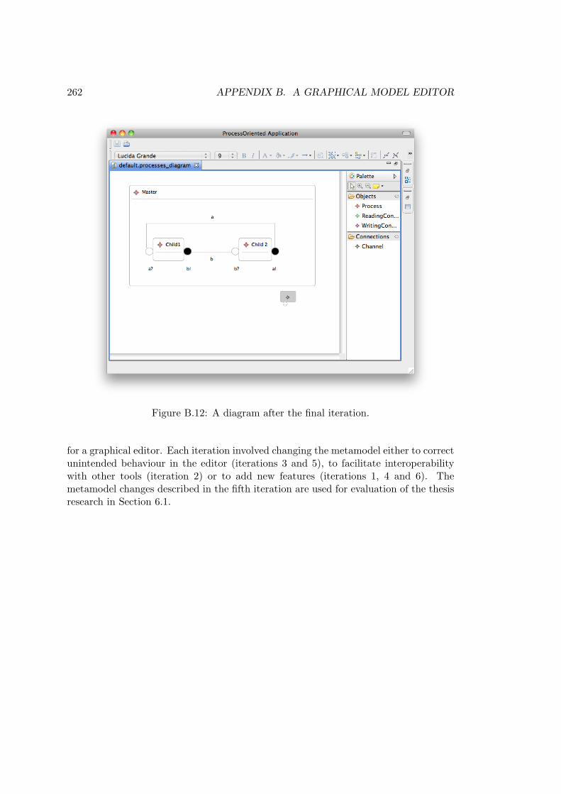
262 APPENDIX B. A GRAPHICAL MODEL EDITOR
Figure B.12: A diagram after the final iteration.
for a graphical editor. Each iteration involved changing the metamodel either to correctunintended behaviour in the editor (iterations 3 and 5), to facilitate interoperabilitywith other tools (iteration 2) or to add new features (iterations 1, 4 and 6). Themetamodel changes described in the fifth iteration are used for evaluation of the thesisresearch in Section 6.1.

Appendix C
Co-evolution Examples
This appendix describes the co-evolution examples used for evaluation in Chapter 6.The examples were taken from real-world MDE projects and are distinct from theexamples used for analysis in Chapter 4.
Below, each section details examples from one project, describes metamodel changesand presents model migration strategies. Each model migration strategy is presentedin the three model migration languages used for evaluating conservative copy in Sec-tion 6.2, and lines that contain a model operation (a statement that changes the mi-grated model) are highlighted. Section 6.2 describes model operations and the threemodel migration languages in more detail.
C.1 Newsgroups Examples
The first set of examples were taken from a project that performed statistical analysisof NNTP newsgroups, developed by Dimitris Kolovos, a lecturer in this department.The analysis was implemented using a metamodel to capture domain-specific concepts,a text-to-model transformation for parsing newsgroup messages, and a model-to-modeltransformation for recording the results of the analysis.
The metamodel and transformations were developed in an iterative and incrementalmanner. Five iterations of the metamodel and transformations were made available byKolovos, two of which involved metamodel changes that affected the conformance ofexisting models and are described below. In the other three iterations, the metamodelchanges were additive, did not lead to model migration, and are not described here.
C.1.1 Extract Person
At the start of the second iteration, the newsgroups metamodel, show in Figure C.1(a),captured two domain concepts, newsgroups and articles. The iteration involved sepa-rating the domain concepts of authors and articles. At the start of the iteration, theArticle class defined a string attribute called sender as shown in Figure C.1(a). Tomake it easier to recognise when several articles were written by the same person, the
263

264 APPENDIX C. CO-EVOLUTION EXAMPLES
(a) Original metamodel.
(b) Evolved metamodel.
Figure C.1: Newsgroups metamodel during the Extract Person iteration
Person class was introduced, and the sender attribute was replaced with a referenceto the Person class as shown in Figure C.1(b).
Existing models were migrated by deriving a Person object from the senderfeature of each Article. The values of the sender feature used one of two forms:[email protected] (Full Name) or "Full Name" [email protected].
Listings C.1, C.2 and C.3 show the model migration strategy in ATL, COPE andFlock respectively. The toEmail() and toName() operations are used to extractnames and email addresses, are defined without using any model operations, and areomitted from the listings below.
1 module ExtractPerson;
2
3 create Migrated : After from Original : Before;
4
5 rule Newsgroups {
6 from
7 o : Before!Newsgroup
8 to
9 m : After!Newsgroup (
10 articles <- o.articles
11 )
12 }
13
14 rule Articles {
15 from

C.1. NEWSGROUPS EXAMPLES 265
16 o : Before!Article
17 to
18 m : After!Article (
19 articleId <- o.articleId,
20 subject <- o.subject,
21 newsgroups <- o.newsgroups,
22 inReplyTo <- o.inReplyTo,
23 date <- o.date,
24 sender <- p
25 ),
26 p : After!Person (
27 name <- o.sender.toName(),
28 email <- o.sender.toEmail()
29 )
30 }
Listing C.1: The Newsgroup Extract Person migration in ATL
1 toPerson = { str ->
2 def person = personClass.newInstance();
3 person.email = str.toEmail()
4 person.name = str.toName()
5 return person
6 }
7
8 for (article in extractperson.Article.allInstances) {
9 def sender = article.unset(sender)
10 article.sender = toPerson(sender)
11 }
Listing C.2: The Newsgroup Extract Person migration in Groovy-for-COPE
1 migrate Article {
2 migrated.sender := original.sender.toPerson();
3 }
4
5 operation String toPerson() : Migrated!Person {
6 var person := new Migrated!Person;
7 person.name := self.toName();
8 person.email := self.toEmail();
9 return person;
10 }
Listing C.3: The Newsgroup Extract Person migration in Flock

266 APPENDIX C. CO-EVOLUTION EXAMPLES
(a) Original metamodel.
(b) Evolved metamodel.
Figure C.2: Newsgroups metamodel during the Resolve Replies iteration
C.1.2 Resolve Replies
The Resolve Replies iteration made explicit the lineage of each article by moving repliesto an article such that they were contained in the original article. At the start ofthe iteration (Figure C.2(a)), each Article was assigned a unique identifier in thearticleId feature. The inReplyTo feature was specified for Articles writtenin reply to others. At the end of the iteration, the inReplyTo attribute was re-placed with a reference of type Article. The inReplyTo attribute was renamed toinReplyToId (and, in a future iteration, was removed from the metamodel).
Listings C.4, C.5 and C.6 show the model migration strategy in ATL, COPE andFlock respectively. Migration involved dereferencing the inReplyTo value to deter-mine a parent Article, and then setting the inReplyTo reference to the parentArticle.
1 module ResolveReplies;
2
3 create Migrated : After from Original : Before;
4
5 rule Newsgroups {
6 from
7 o : Before!Newsgroup
8 to

C.1. NEWSGROUPS EXAMPLES 267
9 m : After!Newsgroup (
10 articles <- o.articles
11 )
12 }
13
14 rule Articles {
15 from
16 o : Before!Article
17 to
18 m : After!Article (
19 articleId <- o.articleId,
20 subject <- o.subject,
21 newsgroups <- o.newsgroups,
22 inReplyToId <- o.inReplyTo,
23 date <- o.date,
24 sender <- o.sender
25 )
26 do {
27 if (not o.inReplyTo.oclIsUndefined() and After!Article.allInstances()->exists
(a|a.articleId = o.inReplyTo)) {
28 After!Article.allInstances()->select(a|a.articleId = o.inReplyTo)->first().
replies <- m;
29 }
30 }
31 }
Listing C.4: The Newsgroup Resolve Replies migration in ATL
1 for (article in extractperson.Article.allInstances) {
2 def replyToId = article.unset(replyTo)
3 article.replyToId = replyToId
4 article.replyTo = Article.allInstances.find { it.articledId = article.replyToId
}
5 }
Listing C.5: The Newsgroup Resolve Replies migration in Groovy-for-COPE
1 migrate Article {
2 migrated.inReplyToId := original.inReplyTo;
3 migrated.inReplyTo := Migrated!Article.all.selectOne(a|a.articleId = migrated.
inReplyToId);
4 }
Listing C.6: The Newsgroup Resolve Replies migration in Flock

268 APPENDIX C. CO-EVOLUTION EXAMPLES
C.2 UML Example
This section describes the co-evolution example taken from the evolution of the UnifiedModeling Language (UML) between versions 1.4 [OMG 2001] and 2.2 [OMG 2007b].Activity diagrams, in particular, changed radically between UML versions 1.4 and 2.2.In the former, activities were defined as a special case of state machines, while in thelatter they were defined with a more general semantic base1 [Selic 2005].
The UML 1.4 and 2.2 specifications are defined in different metamodelling lan-guages. The former uses XMI 1.4 and the latter XMI 2.2. Of the co-evolution toolsdiscussed in this thesis, only Epsilon Flock interoperates with XMI 1.4. To enable theuse of other co-evolution tools with the UML metamodel changes, the author recon-structed part of the UML 1.4 metamodel in XMI 2.2.
The migration semantics were identified by comparing the UML 1.4 and UML 2.2specifications, and by discussing the metamodel evolution with other UML experts.As described in Section 6.4, the UML 2.2 specification appears to be ambiguous withrespect to the way in which UML 1.4 ObjectFlowStates should be migrated to con-form to the UML 2.2 metamodel. The migration strategies presented here assume thesemantics of the core task described in Section 6.4: ObjectFlowStates are replacedwith ObjectNodes.
C.2.1 Activity Diagrams
Figures C.3(a) and C.3(b) are simplifications of the activity diagram metamodels fromversions 1.4 and 2.2 of the UML specification, respectively. In the interest of clarity,some features and abstract classes have been removed from Figures C.3(a) and C.3(b).
Some differences between Figures C.3(a) and C.3(b) are: activities have beenchanged such that they comprise nodes and edges, actions replace states in UML 2.2,and the subtypes of control node replace pseudostates.
Listings C.7, C.8 and C.9 show the model migration strategy in ATL, COPE andFlock respectively. Migration mostly involved restructuring data by storing values infeatures of a different name, and retyping Pseudeostates.
1 module ActivityGraph;
2
3 create Migrated : After from Original : Before;
4
5 rule ActivityGraph {
6 from
7 o : Before!ActivityGraph
8 to
9 p : After!Package (
10 packagedElement <- m
11 ),
12 m : After!Activity (
1A variant of generalised coloured Petri nets.

C.2. UML EXAMPLE 269
(a) Original metamodel.
(b) Evolved metamodel.
Figure C.3: Activities in UML 1.4 and UML 2.2

270 APPENDIX C. CO-EVOLUTION EXAMPLES
13 name <- o.name,
14 node <- o.top.subvertex,
15 edge <- o.transitions,
16 group <- o.partition
17 )
18 }
19
20 rule Partitions {
21 from
22 o : Before!Partition
23 to
24 p : After!ActivityPartition (
25 name <- o.name,
26 edge <- o.contents->select(c|c.oclIsKindOf(Before!Transition)),
27 node <- o.contents->reject(c|c.oclIsKindOf(Before!ObjectFlowState))
28 )
29 }
30
31 rule ActionState2OpaqueAction {
32 from
33 o : Before!ActionState
34 to
35 p : After!OpaqueAction (
36 name <- o.name
37 )
38 }
39
40 rule Initials {
41 from
42 o : Before!Pseudostate (
43 o.kind = #inital
44 )
45 to
46 p : After!InitialNode
47 }
48
49 rule Decisions {
50 from
51 o : Before!Pseudostate (
52 o.kind = #junction
53 )
54 to
55 p : After!DecisionNode
56 }
57
58 rule Forks {
59 from

C.2. UML EXAMPLE 271
60 o : Before!Pseudostate (
61 o.kind = #fork
62 )
63 to
64 p : After!ForkNode
65 }
66
67 rule Joins {
68 from
69 o : Before!Pseudostate (
70 o.kind = #join
71 )
72 to
73 p : After!MergeNode
74 }
75
76 rule Finals {
77 from
78 o : Before!FinalState
79 to
80 p : After!ActivityFinalNode
81 }
82
83 rule ObjectFlows {
84 from
85 o : Before!Transition (
86 o.target.oclIsTypeOf(Before!ObjectFlowState)
87 )
88 to
89 p : After!ObjectFlow (
90 source <- o.source,
91 target <- o.target.outgoing->first().target
92 )
93 }
94
95 rule ControlFlows {
96 from
97 o : Before!Transition (
98 not o.source.oclIsTypeOf(Before!ObjectFlowState) and
99 not o.target.oclIsTypeOf(Before!ObjectFlowState)
100 )
101 to
102 p : After!ControlFlow (
103 guard <- o.guard,
104 source <- o.source,
105 target <- o.target
106 )

272 APPENDIX C. CO-EVOLUTION EXAMPLES
107 }
108
109 rule Guards {
110 from
111 o : Before!Guard
112 to
113 p : After!OpaqueExpression (
114 body <- o.expression.body
115 )
116 }
Listing C.7: UML activity diagram migration in ATL
1 for (model in activities.Model.allInstances) {
2 model.migrate(activities.Package)
3 def ownedElement = model.unset(ownedElement)
4 model.packagedElement = ownedElement
5 }
6
7 for (activity in activities.ActivityGraph.allInstances) {
8 activity.migrate(activities.Activity)
9 def top = activity.unset(top)
10 activity.node = top.subvertex
11 def transitions = activity.unset(transitions)
12 activity.edge = transitions
13 def partition = activity.unset(partition)
14 activity.group = partition
15 }
16
17 for (partition in activities.ActivityGraph.allInstances) {
18 def contents = partition.unset(contents)
19 partition.edges = contents.findAll{it -> it instanceof activities.Transition}
20 partition.nodes = contents.findAll{it -> it instanceof activities.StateVertex
and not (it instanceof activities.ObjectFlowState)}
21 }
22
23 for (action in activities.ActionState.allInstances) {
24 action.migrate(activities.OpaqueAction)
25 }
26
27 for (pseudostate in activities.Pseudeostate) {
28 switch ( pseudostate.kind.toString() ) {
29 case "pk_initial":
30 pseudeostate.migrate(activities.InitialNode); break
31 case "pk_junction"
32 pseudeostate.migrate(activities.DecisionNode); break
33 case "pk_fork"

C.2. UML EXAMPLE 273
34 pseudeostate.migrate(activities.ForkNode); break
35 case "pk_join"
36 pseudeostate.migrate(activities.JoinNode); break
37 }
38 }
39
40 for (finalstate in activities.FinalState.allInstances) {
41 finalstate.migrate(activities.ActivityFinalNode)
42 }
43
44 for (transition in activities.ObjectFlow.allInstances.findAll{it -> it.target
instanceof activities.ObjectFlowState}) {
45 transition.target = transition.target.outgoing.first.target
46 }
47
48 for (transition in activities.Transition.allInstances) {
49 transition.migrate(activities.ControlFlow)
50 }
51
52 for (guard in activities.Guard.allInstances) {
53 transition.migrate(activities.OpaqueExpression)
54 def expression = transition.unset(expression)
55 transition.body = expression.body
56 }
Listing C.8: UML activity diagram migration in Groovy-for-COPE
1 migrate Model to Package {
2 migrated.packagedElement := original.ownedElement.equivalent();
3 }
4
5 migrate ActivityGraph to Activity {
6 migrated.node := original.top.subvertex.equivalent();
7 migrated.edge := original.transitions.equivalent();
8 }
9
10 migrate Partition to ActivityPartition {
11 migrated.edges := original.contents.collect(e : Transition | e.equivalent());
12 migrated.nodes := original.contents.reject(ofs : ObjectFlowState | true).
collect(n : StateVertex | n.equivalent());
13 }
14
15 migrate ActionState to OpaqueAction
16
17 migrate Pseudostate to InitialNode when: original.kind.toString() = ’pk_initial’
18 migrate Pseudostate to DecisionNode when: original.kind.toString() = ’
pk_junction’

274 APPENDIX C. CO-EVOLUTION EXAMPLES
19 migrate Pseudostate to ForkNode when: original.kind.toString() = ’pk_fork’
20 migrate Pseudostate to JoinNode when: original.kind.toString() = ’pk_join’
21
22 migrate FinalState to ActivityFinalNode
23
24 migrate Transition to ObjectFlow when: original.target.isTypeOf(ObjectFlowState)
{
25 migrated.source := original.source.equivalent();
26 migrated.target := original.target.outgoing.first.target.equivalent();
27 }
28
29 migrate Transition to ControlFlow
30
31 migrate Guard to OpaqueExpression {
32 migrated.body.add(original.expression.body);
33 }
Listing C.9: UML activity diagram migration in Flock
C.3 GMF Examples
Two co-evolution examples were located in the Graphical Modeling Framework (GMF)project [Gronback 2009]. GMF allows the specification of a graphical concrete syntaxfor metamodel and the generation of graphical model editors from a number of graphicalconcrete syntax models. GMF was discussed in Section 2.3, and used to implement thegraphical editor described in Appendix B.
GMF is implemented in a model-driven manner, and uses several metamodels to de-scribe graphical concrete syntax and graphical model editors. During the developmentof GMF, two of its metamodels have evolved in a manner that has required models tobe migrated. This section describes changes to the GMF Graph metamodel (used todescribe the canvas of a graphical model editor) and the GMF Generator metamodel(used to describe the Java code generated for a graphical model editor).
C.3.1 GMF Graph
The GMF Graph metamodel comprises approximately 60 classes. For clarity, onlythose classes that were affected by the changes made between versions 1.0 and 2.0 ofGMF are shown in Figure C.4. The migration strategies were specified on the completemetamodel, and not only the extract shown here.
The GMF Graph metamodel (Figure C.4) describes the appearance of the generatedgraphical model editor. The metaclasses Canvas, Figure, Node, DiagramLabel,Connection, and Compartment are used to represent components of the graphicalmodel editor to be generated. The evolution in the GMF Graph metamodel was drivenby analysing the usage of the Figure#referencingElements reference, which re-lates Figures to the DiagramElements that use them. As described in the GMF

C.3. GMF EXAMPLES 275
Graph documentation2, the referencingElements reference increased the effortrequired to re-use figures, a common activity for users of GMF. Furthermore, refe-rencingElements was used only by the GMF code generator to determine whetheran accessor should be generated for nested Figures.
During the development of GMF 2.0, the Graph metamodel from GMF 1.0 wasevolved – as shown in Figure 6.15(b) – to facilitate greater re-use of figures by intro-ducing a proxy [Gamma et al. 1995] for Figure, termed FigureDescriptor. Theoriginal referencingElements reference was removed, and an extra metaclass, Ch-ildAccess, was added to make more explicit the original purpose of referencin-gElements (accessing nested Figures).
Listings C.10, C.11 and C.12 show the model migration strategy in ATL, COPEand Flock respectively. Migration involved creating proxy objects for the FigureG-allery#descriptors and FigureDescriptor#accessors features, and movingvalues to those proxy objects.
1 module Graph;
2
3 create Migrated : After from Original : Before;
4
5 rule Canvas2Canvas extends Identity2Identity {
6 from
7 o : Before!Canvas
8 to
9 m : After!Canvas (
10 figures <- o.figures,
11 nodes <- o.nodes,
12 connections <- o.connections,
13 compartments <- o.compartments,
14 labels <- o.labels
15 )
16 }
17 rule FigureGallery2FigureGallery extends Identity2Identity {
18 from
19 o : Before!FigureGallery
20 to
21 m : After!FigureGallery (
22 implementationBundle <- o.implementationBundle
23 )
24 }
25 abstract rule Identity2Identity {
26 from
27 o : Before!Identity
28 to
29 m : After!Identity (
30 name <- o.name
2http://wiki.eclipse.org/GMFGraph_Hints

276 APPENDIX C. CO-EVOLUTION EXAMPLES
(a) Original metamodel.
(b) Evolved metamodel.
Figure C.4: The Graph metamodel in GMF 1.0 and GMF 2.0

C.3. GMF EXAMPLES 277
31 )
32 }
33 abstract rule DiagramElement2DiagramElement extends Identity2Identity {
34 from
35 o : Before!DiagramElement
36 to
37 m : After!DiagramElement (
38 figure <- o.figure,
39 facets <- o.facets
40 )
41 }
42 rule Node2Node extends DiagramElement2DiagramElement {
43 from
44 o : Before!Node
45 to
46 m : After!Node (
47 resizeConstraint <- o.resizeConstraint,
48 affixedParentSide <- o.affixedParentSide
49 )
50 }
51 rule Connection2Connection extends DiagramElement2DiagramElement {
52 from
53 o : Before!Connection
54 to
55 m : After!Connection
56 }
57 rule Compartment2Compartment extends DiagramElement2DiagramElement {
58 from
59 o : Before!Compartment
60 to
61 m : After!Compartment (
62 collapsible <- o.collapsible,
63 needsTitle <- o.needsTitle
64 )
65 }
66 rule DiagramLabel2DiagramLabel extends Node2Node {
67 from
68 o : Before!DiagramLabel
69 to
70 m : After!DiagramLabel (
71 elementIcon <- o.elementIcon
72 )
73 }
74 abstract rule VisualFacet2VisualFacet {
75 from
76 o : Before!VisualFacet
77 to

278 APPENDIX C. CO-EVOLUTION EXAMPLES
78 m : After!VisualFacet
79 }
80 rule GeneralFacet2GeneralFacet extends VisualFacet2VisualFacet {
81 from
82 o : Before!GeneralFacet
83 to
84 m : After!GeneralFacet (
85 identifier <- o.identifier,
86 data <- o.data
87 )
88 }
89 rule AlignmentFacet2AlignmentFacet extends VisualFacet2VisualFacet {
90 from
91 o : Before!AlignmentFacet
92 to
93 m : After!AlignmentFacet (
94 alignment <- o.alignment
95 )
96 }
97 rule GradientFacet2GradientFacet extends VisualFacet2VisualFacet {
98 from
99 o : Before!GradientFacet
100 to
101 m : After!GradientFacet (
102 direction <- o.direction
103 )
104 }
105 rule LabelOffsetFacet2LabelOffsetFacet extends VisualFacet2VisualFacet {
106 from
107 o : Before!LabelOffsetFacet
108 to
109 m : After!LabelOffsetFacet (
110 x <- o.x,
111 y <- o.y
112 )
113 }
114 rule DefaultSizeFacet2DefaultSizeFacet extends VisualFacet2VisualFacet {
115 from
116 o : Before!DefaultSizeFacet
117 to
118 m : After!DefaultSizeFacet (
119 defaultSize <- o.defaultSize
120 )
121 }
122 abstract rule Figure2Figure extends Layoutable2Layoutable {
123 from
124 o : Before!Figure

C.3. GMF EXAMPLES 279
125 to
126 m : After!Figure (
127 foregroundColor <- o.foregroundColor,
128 backgroundColor <- o.backgroundColor,
129 maximumSize <- o.maximumSize,
130 minimumSize <- o.minimumSize,
131 preferredSize <- o.preferredSize,
132 font <- o.font,
133 insets <- o.insets,
134 border <- o.border,
135 location <- o.location,
136 size <- o.size
137 )
138 }
139 rule FigureRef2FigureRef extends Layoutable2Layoutable {
140 from
141 o : Before!FigureRef
142 to
143 m : After!FigureRef (
144 figure <- o.figure
145 )
146 }
147 abstract rule Shape2Shape extends Figure2Figure {
148 from
149 o : Before!Shape
150 to
151 m : After!Shape (
152 outline <- o.outline,
153 fill <- o.fill,
154 lineWidth <- o.lineWidth,
155 lineKind <- o.lineKind,
156 xorFill <- o.xorFill,
157 xorOutline <- o.xorOutline,
158 resolvedChildren <- o.resolvedChildren
159 )
160 }
161 rule Label2Label extends Figure2Figure {
162 from
163 o : Before!Label
164 to
165 m : After!Label (
166 text <- o.text
167 )
168 }
169 rule LabeledContainer2LabeledContainer extends Figure2Figure {

280 APPENDIX C. CO-EVOLUTION EXAMPLES
170 from
171 o : Before!LabeledContainer
172 to
173 m : After!LabeledContainer
174 }
175 rule Rectangle2Rectangle extends Shape2Shape {
176 from
177 o : Before!Rectangle
178 to
179 m : After!Rectangle
180 }
181 rule RoundedRectangle2RoundedRectangle extends Shape2Shape {
182 from
183 o : Before!RoundedRectangle
184 to
185 m : After!RoundedRectangle (
186 cornerWidth <- o.cornerWidth,
187 cornerHeight <- o.cornerHeight
188 )
189 }
190 rule Ellipse2Ellipse extends Shape2Shape {
191 from
192 o : Before!Ellipse
193 to
194 m : After!Ellipse
195 }
196 rule Polyline2Polyline extends Shape2Shape {
197 from
198 o : Before!Polyline
199 to
200 m : After!Polyline (
201 template <- o.template
202 )
203 }
204 rule Polygon2Polygon extends Polyline2Polyline {
205 from
206 o : Before!Polygon
207 to
208 m : After!Polygon
209 }
210 rule ScalablePolygon2ScalablePolygon extends Polygon2Polygon {
211 from
212 o : Before!ScalablePolygon
213 to
214 m : After!ScalablePolygon
215 }
216 rule PolylineConnection2PolylineConnection extends Polyline2Polyline {

C.3. GMF EXAMPLES 281
217 from
218 o : Before!PolylineConnection
219 to
220 m : After!PolylineConnection (
221 sourceDecoration <- o.sourceDecoration,
222 targetDecoration <- o.targetDecoration
223 )
224 }
225 rule PolylineDecoration2PolylineDecoration extends Polyline2Polyline {
226 from
227 o : Before!PolylineDecoration
228 to
229 m : After!PolylineDecoration
230 }
231 rule PolygonDecoration2PolygonDecoration extends Polygon2Polygon {
232 from
233 o : Before!PolygonDecoration
234 to
235 m : After!PolygonDecoration
236 }
237 abstract rule CustomClass2CustomClass {
238 from
239 o : Before!CustomClass
240 to
241 m : After!CustomClass (
242 qualifiedClassName <- o.qualifiedClassName,
243 attributes <- o.attributes
244 )
245 }
246 rule CustomAttribute2CustomAttribute {
247 from
248 o : Before!CustomAttribute
249 to
250 m : After!CustomAttribute (
251 name <- o.name,
252 value <- o.value,
253 directAccess <- o.directAccess,
254 multiStatementValue <- o.multiStatementValue
255 )
256 }
257 rule FigureAccessor2FigureAccessor {
258 from
259 o : Before!FigureAccessor
260 to
261 m : After!FigureAccessor (
262 accessor <- o.accessor,
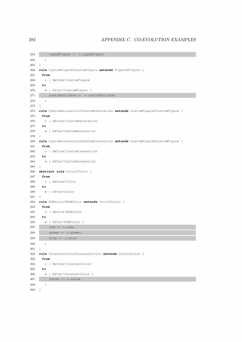
282 APPENDIX C. CO-EVOLUTION EXAMPLES
263 typedFigure <- o.typedFigure
264 )
265 }
266 rule CustomFigure2CustomFigure extends Figure2Figure {
267 from
268 o : Before!CustomFigure
269 to
270 m : After!CustomFigure (
271 customChildren <- o.customChildren
272 )
273 }
274 rule CustomDecoration2CustomDecoration extends CustomFigure2CustomFigure {
275 from
276 o : Before!CustomDecoration
277 to
278 m : After!CustomDecoration
279 }
280 rule CustomConnection2CustomConnection extends CustomFigure2CustomFigure {
281 from
282 o : Before!CustomConnection
283 to
284 m : After!CustomConnection
285 }
286 abstract rule Color2Color {
287 from
288 o : Before!Color
289 to
290 m : After!Color
291 }
292 rule RGBColor2RGBColor extends Color2Color {
293 from
294 o : Before!RGBColor
295 to
296 m : After!RGBColor (
297 red <- o.red,
298 green <- o.green,
299 blue <- o.blue
300 )
301 }
302 rule ConstantColor2ConstantColor extends Color2Color {
303 from
304 o : Before!ConstantColor
305 to
306 m : After!ConstantColor (
307 value <- o.value
308 )
309 }

C.3. GMF EXAMPLES 283
310 abstract rule Font2Font {
311 from
312 o : Before!Font
313 to
314 m : After!Font
315 }
316 rule BasicFont2BasicFont extends Font2Font {
317 from
318 o : Before!BasicFont
319 to
320 m : After!BasicFont (
321 faceName <- o.faceName,
322 height <- o.height,
323 style <- o.style
324 )
325 }
326 rule Point2Point {
327 from
328 o : Before!Point
329 to
330 m : After!Point (
331 x <- o.x,
332 y <- o.y
333 )
334 }
335 rule Dimension2Dimension {
336 from
337 o : Before!Dimension
338 to
339 m : After!Dimension (
340 dx <- o.dx,
341 dy <- o.dy
342 )
343 }
344 rule Insets2Insets {
345 from
346 o : Before!Insets
347 to
348 m : After!Insets (
349 top <- o.top,
350 left <- o.left,
351 bottom <- o.bottom,
352 right <- o.right
353 )
354 }
355 abstract rule Border2Border {
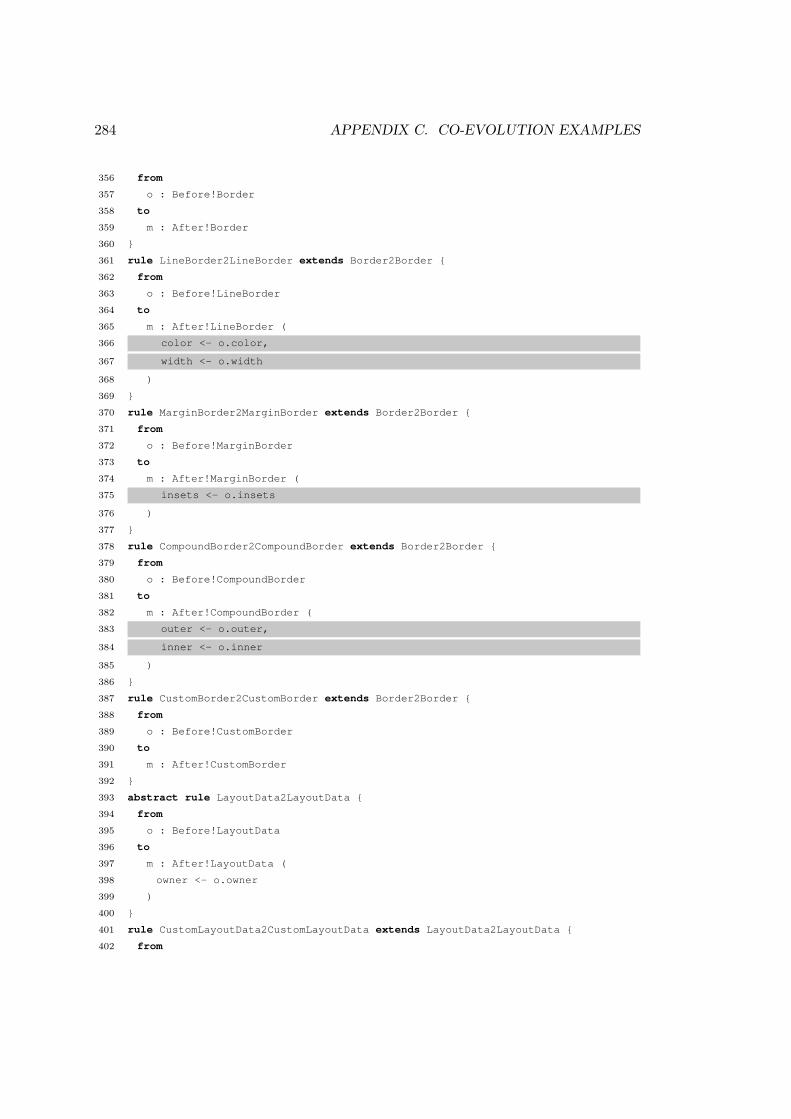
284 APPENDIX C. CO-EVOLUTION EXAMPLES
356 from
357 o : Before!Border
358 to
359 m : After!Border
360 }
361 rule LineBorder2LineBorder extends Border2Border {
362 from
363 o : Before!LineBorder
364 to
365 m : After!LineBorder (
366 color <- o.color,
367 width <- o.width
368 )
369 }
370 rule MarginBorder2MarginBorder extends Border2Border {
371 from
372 o : Before!MarginBorder
373 to
374 m : After!MarginBorder (
375 insets <- o.insets
376 )
377 }
378 rule CompoundBorder2CompoundBorder extends Border2Border {
379 from
380 o : Before!CompoundBorder
381 to
382 m : After!CompoundBorder (
383 outer <- o.outer,
384 inner <- o.inner
385 )
386 }
387 rule CustomBorder2CustomBorder extends Border2Border {
388 from
389 o : Before!CustomBorder
390 to
391 m : After!CustomBorder
392 }
393 abstract rule LayoutData2LayoutData {
394 from
395 o : Before!LayoutData
396 to
397 m : After!LayoutData (
398 owner <- o.owner
399 )
400 }
401 rule CustomLayoutData2CustomLayoutData extends LayoutData2LayoutData {
402 from
C.3. GMF EXAMPLES 285
403 o : Before!CustomLayoutData
404 to
405 m : After!CustomLayoutData
406 }
407 rule GridLayoutData2GridLayoutData extends LayoutData2LayoutData {
408 from
409 o : Before!GridLayoutData
410 to
411 m : After!GridLayoutData (
412 grabExcessHorizontalSpace <- o.grabExcessHorizontalSpace,
413 grabExcessVerticalSpace <- o.grabExcessVerticalSpace,
414 verticalAlignment <- o.verticalAlignment,
415 horizontalAlignment <- o.horizontalAlignment,
416 verticalSpan <- o.verticalSpan,
417 horizontalSpan <- o.horizontalSpan,
418 horizontalIndent <- o.horizontalIndent,
419 sizeHint <- o.sizeHint
420 )
421 }
422 rule BorderLayoutData2BorderLayoutData extends LayoutData2LayoutData {
423 from
424 o : Before!BorderLayoutData
425 to
426 m : After!BorderLayoutData (
427 alignment <- o.alignment,
428 vertical <- o.vertical
429 )
430 }
431 abstract rule Layoutable2Layoutable {
432 from
433 o : Before!Layoutable
434 to
435 m : After!Layoutable (
436 layoutData <- o.layoutData,
437 layout <- o.layout
438 )
439 }
440 abstract rule Layout2Layout {
441 from
442 o : Before!Layout
443 to
444 m : After!Layout
445 }
446 rule CustomLayout2CustomLayout extends Layout2Layout {
447 from
448 o : Before!CustomLayout

286 APPENDIX C. CO-EVOLUTION EXAMPLES
449 to
450 m : After!CustomLayout
451 }
452 rule GridLayout2GridLayout extends Layout2Layout {
453 from
454 o : Before!GridLayout
455 to
456 m : After!GridLayout (
457 numColumns <- o.numColumns,
458 equalWidth <- o.equalWidth,
459 margins <- o.margins,
460 spacing <- o.spacing
461 )
462 }
463 rule BorderLayout2BorderLayout extends Layout2Layout {
464 from
465 o : Before!BorderLayout
466 to
467 m : After!BorderLayout (
468 spacing <- o.spacing
469 )
470 }
471 rule FlowLayout2FlowLayout extends Layout2Layout {
472 from
473 o : Before!FlowLayout
474 to
475 m : After!FlowLayout (
476 vertical <- o.vertical,
477 matchMinorSize <- o.matchMinorSize,
478 forceSingleLine <- o.forceSingleLine,
479 majorAlignment <- o.majorAlignment,
480 minorAlignment <- o.minorAlignment,
481 majorSpacing <- o.majorSpacing,
482 minorSpacing <- o.minorSpacing
483 )
484 }
485 rule XYLayout2XYLayout extends Layout2Layout {
486 from
487 o : Before!XYLayout
488 to
489 m : After!XYLayout
490 }
491 rule XYLayoutData2XYLayoutData extends LayoutData2LayoutData {
492 from
493 o : Before!XYLayoutData
494 to

C.3. GMF EXAMPLES 287
495 m : After!XYLayoutData (
496 topLeft <- o.topLeft,
497 size <- o.size
498 )
499 }
500 rule StackLayout2StackLayout extends Layout2Layout {
501 from
502 o : Before!StackLayout
503 to
504 m : After!StackLayout
505 }
Listing C.10: GMF Graph migration in ATL
1 for (gallery in graph.FigureGallery.allInstances) {
2 while(not gallery.figures.isEmpty()) {
3 def figure = gallery.figures.first()
4 def descriptor = graph.FigureDescriptor.newInstance()
5
6 descriptor.name = figure.name
7 descriptor.actualFigure = figure
8
9 figure.set(descriptor, descriptor)
10
11 figure.children.findAll{ it -> it instanceof graph.Label}.each do |it|
12 def accessor = graph.ChildAccess.newInstance()
13
14 accessor.figure = it
15 descriptor.accessors.add(accessor)
16
17 it.set(accessor, accessor)
18 end
19
20 return descriptor;
21 }
22 }
23
24 for (diagramElement in graph.DiagramElement.allInstances()) {
25 diagramElement.figure.unset(descriptor)
26 diagramElement.figure = descriptor
27 }
28
29 for (diagramLabel in graph.DiagramLabel.allInstances()) {
30 diagramElement.figure.unset(accessor)
31 diagramElement.accessor = accessor

288 APPENDIX C. CO-EVOLUTION EXAMPLES
32 }
Listing C.11: GMF Graph migration in Groovy-for-COPE
1 migrate FigureGallery {
2 while (not migrated.figures.isEmpty()) {
3 migrated.descriptors.add(migrated.figures.first.createDescriptor());
4 }
5 }
6
7 migrate Compartment {
8 migrated.figure := original.figure.equivalent().˜descriptor;
9 }
10
11 migrate Connection {
12 migrated.figure := original.figure.equivalent().˜descriptor;
13 }
14
15 migrate DiagramLabel {
16 migrated.figure := original.figure.equivalent().˜descriptor;
17 migrated.accessor := original.figure.equivalent().˜accessor;
18 }
19
20 migrate Node {
21 migrated.figure := original.figure.equivalent().˜descriptor;
22 }
23
24 operation Migrated!Figure createDescriptor() : Migrated!FigureDescriptor {
25 var descriptor := new Migrated!FigureDescriptor;
26
27 descriptor.name := self.name;
28 descriptor.actualFigure := self;
29
30 self.˜descriptor := descriptor;
31
32 self.children.forAll(l : Migrated!Label | l.addAccessor(descriptor));
33
34 return descriptor;
35 }
36
37 operation Migrated!Label addAccessor(descriptor : Migrated!FigureDescriptor) {
38 var accessor := new Migrated!ChildAccess;
39
40 accessor.figure := self;
41 self.˜descriptor := descriptor;
42 self.˜accessor := accessor;
43 descriptor.accessors.add(accessor);

C.3. GMF EXAMPLES 289
44 }
Listing C.12: GMF Graph migration in Flock
C.3.2 GMF Generator
During the development of GMF v2.2, the Generator metamodel evolved to makeexplicit the use of ContextMenus and Parsers. In previous versions of GMF, Cont-extMenus and Parsers were not customisable via the Generator metamodel. Instead,the GMF runtime created menus and parsers automatically at runtime. The GMFgenerator metamodel is too large to show here, as it comprises approximately 150classes and the changes made between versions 2.1 and 2.2 of GMF directly affected23 classes.
Listings C.13, C.13 and C.13 show the model migration strategy in ATL, COPEand Flock respectively. Migration involved populating ContextMenus from existingdiagram elements, and creating Parsers for built-in and user-defined languages.
1 module GenModel2009;
2
3 create Migrated : After from Original : Before;
4
5 rule GenEditorGenerator2GenEditorGenerator {
6 from
7 o : Before!GenEditorGenerator
8 to
9 m : After!GenEditorGenerator (
10 audits <- o.audits,
11 metrics <- o.metrics,
12 diagram <- o.diagram,
13 plugin <- o.plugin,
14 editor <- o.editor,
15 navigator <- o.navigator,
16 diagramUpdater <- o.diagramUpdater,
17 propertySheet <- o.propertySheet,
18 application <- o.application,
19 domainGenModel <- o.domainGenModel,
20 packageNamePrefix <- o.packageNamePrefix,
21 modelID <- o.modelID,
22 sameFileForDiagramAndModel <- o.sameFileForDiagramAndModel,
23 diagramFileExtension <- o.diagramFileExtension,
24 domainFileExtension <- o.domainFileExtension,
25 dynamicTemplates <- o.dynamicTemplates,
26 templateDirectory <- o.templateDirectory,
27 copyrightText <- o.copyrightText,
28 expressionProviders <- o.expressionProviders,

290 APPENDIX C. CO-EVOLUTION EXAMPLES
29 modelAccess <- o.modelAccess
30 )
31 }
32 rule GenDiagram2GenDiagram extends GenContainerBase2GenContainerBase {
33 from
34 o : Before!GenDiagram
35 to
36 m : After!GenDiagram (
37 domainDiagramElement <- o.domainDiagramElement,
38 childNodes <- o.childNodes,
39 topLevelNodes <- o.topLevelNodes,
40 links <- o.links,
41 compartments <- o.compartments,
42 palette <- o.palette,
43 synchronized <- o.synchronized,
44 preferences <- o.preferences,
45 preferencePages <- o.preferencePages
46 )
47 }
48 rule GenEditorView2GenEditorView {
49 from
50 o : Before!GenEditorView
51 to
52 m : After!GenEditorView (
53 packageName <- o.packageName,
54 actionBarContributorClassName <- o.actionBarContributorClassName,
55 className <- o.className,
56 iconPath <- o.iconPath,
57 iD <- o.iD,
58 eclipseEditor <- o.eclipseEditor,
59 contextID <- o.contextID
60 )
61 }
62 abstract rule GenPreferencePage2GenPreferencePage {
63 from
64 o : Before!GenPreferencePage
65 to
66 m : After!GenPreferencePage (
67 iD <- o.iD,
68 name <- o.name,
69 children <- o.children
70 )
71 }
72 rule GenCustomPreferencePage2GenCustomPreferencePage extends
GenPreferencePage2GenPreferencePage {

C.3. GMF EXAMPLES 291
73 from
74 o : Before!GenCustomPreferencePage
75 to
76 m : After!GenCustomPreferencePage (
77 qualifiedClassName <- o.qualifiedClassName
78 )
79 }
80 rule GenStandardPreferencePage2GenStandardPreferencePage extends
GenPreferencePage2GenPreferencePage {
81 from
82 o : Before!GenStandardPreferencePage
83 to
84 m : After!GenStandardPreferencePage (
85 kind <- o.kind
86 )
87 }
88 rule GenDiagramPreferences2GenDiagramPreferences {
89 from
90 o : Before!GenDiagramPreferences
91 to
92 m : After!GenDiagramPreferences (
93 lineStyle <- o.lineStyle,
94 defaultFont <- o.defaultFont,
95 fontColor <- o.fontColor,
96 fillColor <- o.fillColor,
97 lineColor <- o.lineColor,
98 noteFillColor <- o.noteFillColor,
99 noteLineColor <- o.noteLineColor,
100 showConnectionHandles <- o.showConnectionHandles,
101 showPopupBars <- o.showPopupBars,
102 promptOnDelFromModel <- o.promptOnDelFromModel,
103 promptOnDelFromDiagram <- o.promptOnDelFromDiagram,
104 enableAnimatedLayout <- o.enableAnimatedLayout,
105 enableAnimatedZoom <- o.enableAnimatedZoom,
106 enableAntiAlias <- o.enableAntiAlias,
107 showGrid <- o.showGrid,
108 showRulers <- o.showRulers,
109 snapToGrid <- o.snapToGrid,
110 snapToGeometry <- o.snapToGeometry,
111 gridInFront <- o.gridInFront,
112 rulerUnits <- o.rulerUnits,
113 gridSpacing <- o.gridSpacing,
114 gridLineColor <- o.gridLineColor,
115 gridLineStyle <- o.gridLineStyle
116 )

292 APPENDIX C. CO-EVOLUTION EXAMPLES
117 }
118 abstract rule GenFont2GenFont {
119 from
120 o : Before!GenFont
121 to
122 m : After!GenFont
123 }
124 rule GenStandardFont2GenStandardFont extends GenFont2GenFont {
125 from
126 o : Before!GenStandardFont
127 to
128 m : After!GenStandardFont (
129 name <- o.name
130 )
131 }
132 rule GenCustomFont2GenCustomFont extends GenFont2GenFont {
133 from
134 o : Before!GenCustomFont
135 to
136 m : After!GenCustomFont (
137 name <- o.name,
138 height <- o.height,
139 style <- o.style
140 )
141 }
142 abstract rule GenColor2GenColor {
143 from
144 o : Before!GenColor
145 to
146 m : After!GenColor
147 }
148 rule GenRGBColor2GenRGBColor extends GenColor2GenColor {
149 from
150 o : Before!GenRGBColor
151 to
152 m : After!GenRGBColor (
153 red <- o.red,
154 green <- o.green,
155 blue <- o.blue
156 )
157 }
158 rule GenConstantColor2GenConstantColor extends GenColor2GenColor {
159 from
160 o : Before!GenConstantColor
161 to
162 m : After!GenConstantColor (
163 name <- o.name

C.3. GMF EXAMPLES 293
164 )
165 }
166 rule GenDiagramUpdater2GenDiagramUpdater {
167 from
168 o : Before!GenDiagramUpdater
169 to
170 m : After!GenDiagramUpdater (
171 diagramUpdaterClassName <- o.diagramUpdaterClassName,
172 nodeDescriptorClassName <- o.nodeDescriptorClassName,
173 linkDescriptorClassName <- o.linkDescriptorClassName,
174 updateCommandClassName <- o.updateCommandClassName,
175 updateCommandID <- o.updateCommandID
176 )
177 }
178 rule GenPlugin2GenPlugin {
179 from
180 o : Before!GenPlugin
181 to
182 m : After!GenPlugin (
183 iD <- o.iD,
184 name <- o.name,
185 provider <- o.provider,
186 version <- o.version,
187 printingEnabled <- o.printingEnabled,
188 requiredPlugins <- o.requiredPlugins,
189 activatorClassName <- o.activatorClassName
190 )
191 }
192 rule DynamicModelAccess2DynamicModelAccess {
193 from
194 o : Before!DynamicModelAccess
195 to
196 m : After!DynamicModelAccess (
197 packageName <- o.packageName,
198 className <- o.className
199 )
200 }
201 abstract rule GenCommonBase2GenCommonBase {
202 from
203 o : Before!GenCommonBase
204 to
205 m : After!GenCommonBase (
206 diagramRunTimeClass <- o.diagramRunTimeClass,
207 visualID <- o.visualID,
208 elementType <- o.elementType,
209 editPartClassName <- o.editPartClassName,

294 APPENDIX C. CO-EVOLUTION EXAMPLES
210 itemSemanticEditPolicyClassName <- o.itemSemanticEditPolicyClassName,
211 notationViewFactoryClassName <- o.notationViewFactoryClassName,
212 viewmap <- o.viewmap,
213 styles <- o.styles,
214 behaviour <- o.behaviour
215 )
216 }
217 abstract rule Behaviour2Behaviour {
218 from
219 o : Before!Behaviour
220 to
221 m : After!Behaviour
222 }
223 rule CustomBehaviour2CustomBehaviour extends Behaviour2Behaviour {
224 from
225 o : Before!CustomBehaviour
226 to
227 m : After!CustomBehaviour (
228 key <- o.key,
229 editPolicyQualifiedClassName <- o.editPolicyQualifiedClassName
230 )
231 }
232 rule SharedBehaviour2SharedBehaviour extends Behaviour2Behaviour {
233 from
234 o : Before!SharedBehaviour
235 to
236 m : After!SharedBehaviour (
237 delegate <- o.delegate
238 )
239 }
240 rule OpenDiagramBehaviour2OpenDiagramBehaviour extends Behaviour2Behaviour {
241 from
242 o : Before!OpenDiagramBehaviour
243 to
244 m : After!OpenDiagramBehaviour (
245 editPolicyClassName <- o.editPolicyClassName,
246 diagramKind <- o.diagramKind,
247 editorID <- o.editorID,
248 openAsEclipseEditor <- o.openAsEclipseEditor
249 )
250 }
251 abstract rule GenContainerBase2GenContainerBase extends
GenCommonBase2GenCommonBase {
252 from
253 o : Before!GenContainerBase
254 to

C.3. GMF EXAMPLES 295
255 m : After!GenContainerBase (
256 canonicalEditPolicyClassName <- o.canonicalEditPolicyClassName
257 )
258 }
259 abstract rule GenChildContainer2GenChildContainer extends
GenContainerBase2GenContainerBase {
260 from
261 o : Before!GenChildContainer
262 to
263 m : After!GenChildContainer (
264 childNodes <- o.childNodes
265 )
266 }
267 abstract rule GenNode2GenNode extends GenChildContainer2GenChildContainer {
268 from
269 o : Before!GenNode
270 to
271 m : After!GenNode (
272 modelFacet <- o.modelFacet,
273 labels <- o.labels,
274 compartments <- o.compartments,
275 primaryDragEditPolicyQualifiedClassName <- o.
primaryDragEditPolicyQualifiedClassName,
276 graphicalNodeEditPolicyClassName <- o.graphicalNodeEditPolicyClassName,
277 createCommandClassName <- o.createCommandClassName
278 )
279 }
280 rule GenTopLevelNode2GenTopLevelNode extends GenNode2GenNode {
281 from
282 o : Before!GenTopLevelNode
283 to
284 m : After!GenTopLevelNode
285 }
286 rule GenChildNode2GenChildNode extends GenNode2GenNode {
287 from
288 o : Before!GenChildNode
289 to
290 m : After!GenChildNode
291 }
292 rule GenChildSideAffixedNode2GenChildSideAffixedNode extends
GenChildNode2GenChildNode {
293 from
294 o : Before!GenChildSideAffixedNode
295 to
296 m : After!GenChildSideAffixedNode (
297 preferredSideName <- o.preferredSideName

296 APPENDIX C. CO-EVOLUTION EXAMPLES
298 )
299 }
300 rule GenChildLabelNode2GenChildLabelNode extends GenChildNode2GenChildNode {
301 from
302 o : Before!GenChildLabelNode
303 to
304 m : After!GenChildLabelNode (
305 labelReadOnly <- o.labelReadOnly,
306 labelElementIcon <- o.labelElementIcon,
307 labelModelFacet <- o.labelModelFacet
308 )
309 }
310 rule GenCompartment2GenCompartment extends GenChildContainer2GenChildContainer {
311 from
312 o : Before!GenCompartment
313 to
314 m : After!GenCompartment (
315 title <- o.title,
316 canCollapse <- o.canCollapse,
317 hideIfEmpty <- o.hideIfEmpty,
318 needsTitle <- o.needsTitle,
319 node <- o.node,
320 listLayout <- o.listLayout
321 )
322 }
323 rule GenLink2GenLink extends GenCommonBase2GenCommonBase {
324 from
325 o : Before!GenLink
326 to
327 m : After!GenLink (
328 modelFacet <- o.modelFacet,
329 labels <- o.labels,
330 outgoingCreationAllowed <- o.outgoingCreationAllowed,
331 incomingCreationAllowed <- o.incomingCreationAllowed,
332 viewDirectionAlignedWithModel <- o.viewDirectionAlignedWithModel,
333 creationConstraints <- o.creationConstraints,
334 createCommandClassName <- o.createCommandClassName,
335 reorientCommandClassName <- o.reorientCommandClassName,
336 treeBranch <- o.treeBranch
337 )
338 }
339 abstract rule GenLabel2GenLabel extends GenCommonBase2GenCommonBase {
340 from
341 o : Before!GenLabel
342 to
343 m : After!GenLabel (

C.3. GMF EXAMPLES 297
344 readOnly <- o.readOnly,
345 elementIcon <- o.elementIcon,
346 modelFacet <- o.modelFacet
347 )
348 }
349 rule GenNodeLabel2GenNodeLabel extends GenLabel2GenLabel {
350 from
351 o : Before!GenNodeLabel
352 to
353 m : After!GenNodeLabel
354 }
355 rule GenExternalNodeLabel2GenExternalNodeLabel extends GenNodeLabel2GenNodeLabel
{
356 from
357 o : Before!GenExternalNodeLabel
358 to
359 m : After!GenExternalNodeLabel
360 }
361 rule GenLinkLabel2GenLinkLabel extends GenLabel2GenLabel {
362 from
363 o : Before!GenLinkLabel
364 to
365 m : After!GenLinkLabel (
366 link <- o.link,
367 alignment <- o.alignment
368 )
369 }
370 abstract rule ElementType2ElementType {
371 from
372 o : Before!ElementType
373 to
374 m : After!ElementType (
375 diagramElement <- o.diagramElement,
376 uniqueIdentifier <- o.uniqueIdentifier,
377 displayName <- o.displayName,
378 definedExternally <- o.definedExternally
379 )
380 }
381 rule MetamodelType2MetamodelType extends ElementType2ElementType {
382 from
383 o : Before!MetamodelType
384 to
385 m : After!MetamodelType (
386 editHelperClassName <- o.editHelperClassName
387 )
388 }
298 APPENDIX C. CO-EVOLUTION EXAMPLES
389 rule SpecializationType2SpecializationType extends ElementType2ElementType {
390 from
391 o : Before!SpecializationType
392 to
393 m : After!SpecializationType (
394 metamodelType <- o.metamodelType,
395 editHelperAdviceClassName <- o.editHelperAdviceClassName
396 )
397 }
398 rule NotationType2NotationType extends ElementType2ElementType {
399 from
400 o : Before!NotationType
401 to
402 m : After!NotationType
403 }
404 abstract rule ModelFacet2ModelFacet {
405 from
406 o : Before!ModelFacet
407 to
408 m : After!ModelFacet
409 }
410 abstract rule LinkModelFacet2LinkModelFacet extends ModelFacet2ModelFacet {
411 from
412 o : Before!LinkModelFacet
413 to
414 m : After!LinkModelFacet
415 }
416 abstract rule LabelModelFacet2LabelModelFacet extends ModelFacet2ModelFacet {
417 from
418 o : Before!LabelModelFacet
419 to
420 m : After!LabelModelFacet
421 }
422 rule TypeModelFacet2TypeModelFacet extends ModelFacet2ModelFacet {
423 from
424 o : Before!TypeModelFacet
425 to
426 m : After!TypeModelFacet (
427 metaClass <- o.metaClass,
428 containmentMetaFeature <- o.containmentMetaFeature,
429 childMetaFeature <- o.childMetaFeature,
430 modelElementSelector <- o.modelElementSelector,
431 modelElementInitializer <- o.modelElementInitializer
432 )
433 }
434 rule TypeLinkModelFacet2TypeLinkModelFacet extends TypeModelFacet2TypeModelFacet
{

C.3. GMF EXAMPLES 299
435 from
436 o : Before!TypeLinkModelFacet
437 to
438 m : After!TypeLinkModelFacet (
439 sourceMetaFeature <- o.sourceMetaFeature,
440 targetMetaFeature <- o.targetMetaFeature
441 )
442 }
443 rule FeatureLinkModelFacet2FeatureLinkModelFacet extends
LinkModelFacet2LinkModelFacet {
444 from
445 o : Before!FeatureLinkModelFacet
446 to
447 m : After!FeatureLinkModelFacet (
448 metaFeature <- o.metaFeature
449 )
450 }
451 rule FeatureLabelModelFacet2FeatureLabelModelFacet extends
LabelModelFacet2LabelModelFacet {
452 from
453 o : Before!FeatureLabelModelFacet
454 to
455 m : After!FeatureLabelModelFacet (
456 metaFeatures <- o.metaFeatures,
457 viewPattern <- o.viewPattern,
458 editorPattern <- o.editorPattern,
459 editPattern <- o.editPattern,
460 viewMethod <- o.viewMethod,
461 editMethod <- o.editMethod
462 )
463 }
464 rule DesignLabelModelFacet2DesignLabelModelFacet extends
LabelModelFacet2LabelModelFacet {
465 from
466 o : Before!DesignLabelModelFacet
467 to
468 m : After!DesignLabelModelFacet
469 }
470 abstract rule Attributes2Attributes {
471 from
472 o : Before!Attributes
473 to
474 m : After!Attributes
475 }
476 rule ColorAttributes2ColorAttributes extends Attributes2Attributes {
477 from
300 APPENDIX C. CO-EVOLUTION EXAMPLES
478 o : Before!ColorAttributes
479 to
480 m : After!ColorAttributes (
481 foregroundColor <- o.foregroundColor,
482 backgroundColor <- o.backgroundColor
483 )
484 }
485 rule StyleAttributes2StyleAttributes extends Attributes2Attributes {
486 from
487 o : Before!StyleAttributes
488 to
489 m : After!StyleAttributes (
490 fixedFont <- o.fixedFont,
491 fixedForeground <- o.fixedForeground,
492 fixedBackground <- o.fixedBackground
493 )
494 }
495 rule ResizeConstraints2ResizeConstraints extends Attributes2Attributes {
496 from
497 o : Before!ResizeConstraints
498 to
499 m : After!ResizeConstraints (
500 resizeHandles <- o.resizeHandles,
501 nonResizeHandles <- o.nonResizeHandles
502 )
503 }
504 rule DefaultSizeAttributes2DefaultSizeAttributes extends Attributes2Attributes {
505 from
506 o : Before!DefaultSizeAttributes
507 to
508 m : After!DefaultSizeAttributes (
509 width <- o.width,
510 height <- o.height
511 )
512 }
513 rule LabelOffsetAttributes2LabelOffsetAttributes extends Attributes2Attributes {
514 from
515 o : Before!LabelOffsetAttributes
516 to
517 m : After!LabelOffsetAttributes (
518 x <- o.x,
519 y <- o.y
520 )
521 }
522 abstract rule Viewmap2Viewmap {
523 from

C.3. GMF EXAMPLES 301
524 o : Before!Viewmap
525 to
526 m : After!Viewmap (
527 attributes <- o.attributes,
528 requiredPluginIDs <- o.requiredPluginIDs,
529 layoutType <- o.layoutType
530 )
531 }
532 rule FigureViewmap2FigureViewmap extends Viewmap2Viewmap {
533 from
534 o : Before!FigureViewmap
535 to
536 m : After!FigureViewmap (
537 figureQualifiedClassName <- o.figureQualifiedClassName
538 )
539 }
540 rule SnippetViewmap2SnippetViewmap extends Viewmap2Viewmap {
541 from
542 o : Before!SnippetViewmap
543 to
544 m : After!SnippetViewmap (
545 body <- o.body
546 )
547 }
548 rule InnerClassViewmap2InnerClassViewmap extends Viewmap2Viewmap {
549 from
550 o : Before!InnerClassViewmap
551 to
552 m : After!InnerClassViewmap (
553 className <- o.className,
554 classBody <- o.classBody
555 )
556 }
557 rule ParentAssignedViewmap2ParentAssignedViewmap extends Viewmap2Viewmap {
558 from
559 o : Before!ParentAssignedViewmap
560 to
561 m : After!ParentAssignedViewmap (
562 getterName <- o.getterName,
563 setterName <- o.setterName,
564 figureQualifiedClassName <- o.figureQualifiedClassName
565 )
566 }
567 rule ValueExpression2ValueExpression {
568 from
569 o : Before!ValueExpression
302 APPENDIX C. CO-EVOLUTION EXAMPLES
570 to
571 m : After!ValueExpression (
572 body <- o.body
573 )
574 }
575 rule GenConstraint2GenConstraint extends ValueExpression2ValueExpression {
576 from
577 o : Before!GenConstraint
578 to
579 m : After!GenConstraint
580 }
581 rule Palette2Palette {
582 from
583 o : Before!Palette
584 to
585 m : After!Palette (
586 flyout <- o.flyout,
587 groups <- o.groups,
588 packageName <- o.packageName,
589 factoryClassName <- o.factoryClassName
590 )
591 }
592 abstract rule EntryBase2EntryBase {
593 from
594 o : Before!EntryBase
595 to
596 m : After!EntryBase (
597 title <- o.title,
598 description <- o.description,
599 largeIconPath <- o.largeIconPath,
600 smallIconPath <- o.smallIconPath,
601 createMethodName <- o.createMethodName
602 )
603 }
604 abstract rule AbstractToolEntry2AbstractToolEntry extends EntryBase2EntryBase {
605 from
606 o : Before!AbstractToolEntry
607 to
608 m : After!AbstractToolEntry (
609 default <- o.default,
610 qualifiedToolName <- o.qualifiedToolName,
611 properties <- o.properties
612 )
613 }
614 rule ToolEntry2ToolEntry extends AbstractToolEntry2AbstractToolEntry {
615 from

C.3. GMF EXAMPLES 303
616 o : Before!ToolEntry
617 to
618 m : After!ToolEntry (
619 genNodes <- o.genNodes,
620 genLinks <- o.genLinks
621 )
622 }
623 rule StandardEntry2StandardEntry extends AbstractToolEntry2AbstractToolEntry {
624 from
625 o : Before!StandardEntry
626 to
627 m : After!StandardEntry (
628 kind <- o.kind
629 )
630 }
631 abstract rule ToolGroupItem2ToolGroupItem {
632 from
633 o : Before!ToolGroupItem
634 to
635 m : After!ToolGroupItem
636 }
637 rule Separator2Separator extends ToolGroupItem2ToolGroupItem {
638 from
639 o : Before!Separator
640 to
641 m : After!Separator
642 }
643 rule ToolGroup2ToolGroup extends EntryBase2EntryBase {
644 from
645 o : Before!ToolGroup
646 to
647 m : After!ToolGroup (
648 palette <- o.palette,
649 stack <- o.stack,
650 collapse <- o.collapse,
651 entries <- o.entries
652 )
653 }
654 abstract rule GenElementInitializer2GenElementInitializer {
655 from
656 o : Before!GenElementInitializer
657 to
658 m : After!GenElementInitializer
659 }
660 rule GenFeatureSeqInitializer2GenFeatureSeqInitializer extends
GenElementInitializer2GenElementInitializer {
661 from

304 APPENDIX C. CO-EVOLUTION EXAMPLES
662 o : Before!GenFeatureSeqInitializer
663 to
664 m : After!GenFeatureSeqInitializer (
665 initializers <- o.initializers,
666 elementClass <- o.elementClass
667 )
668 }
669 rule GenFeatureValueSpec2GenFeatureValueSpec extends
GenFeatureInitializer2GenFeatureInitializer {
670 from
671 o : Before!GenFeatureValueSpec
672 to
673 m : After!GenFeatureValueSpec (
674 value <- o.value
675 )
676 }
677 rule GenReferenceNewElementSpec2GenReferenceNewElementSpec extends
GenFeatureInitializer2GenFeatureInitializer {
678 from
679 o : Before!GenReferenceNewElementSpec
680 to
681 m : After!GenReferenceNewElementSpec (
682 newElementInitializers <- o.newElementInitializers
683 )
684 }
685 abstract rule GenFeatureInitializer2GenFeatureInitializer {
686 from
687 o : Before!GenFeatureInitializer
688 to
689 m : After!GenFeatureInitializer (
690 feature <- o.feature
691 )
692 }
693 rule GenLinkConstraints2GenLinkConstraints {
694 from
695 o : Before!GenLinkConstraints
696 to
697 m : After!GenLinkConstraints (
698 link <- o.link,
699 sourceEnd <- o.sourceEnd,
700 targetEnd <- o.targetEnd
701 )
702 }
703 rule GenAuditRoot2GenAuditRoot {
704 from
705 o : Before!GenAuditRoot
706 to

C.3. GMF EXAMPLES 305
707 m : After!GenAuditRoot (
708 categories <- o.categories,
709 rules <- o.rules,
710 clientContexts <- o.clientContexts
711 )
712 }
713 rule GenAuditContainer2GenAuditContainer {
714 from
715 o : Before!GenAuditContainer
716 to
717 m : After!GenAuditContainer (
718 id <- o.id,
719 name <- o.name,
720 description <- o.description,
721 path <- o.path,
722 audits <- o.audits
723 )
724 }
725 abstract rule GenRuleBase2GenRuleBase {
726 from
727 o : Before!GenRuleBase
728 to
729 m : After!GenRuleBase (
730 name <- o.name,
731 description <- o.description
732 )
733 }
734 rule GenAuditRule2GenAuditRule extends GenRuleBase2GenRuleBase {
735 from
736 o : Before!GenAuditRule
737 to
738 m : After!GenAuditRule (
739 id <- o.id,
740 rule <- o.rule,
741 target <- o.target,
742 message <- o.message,
743 severity <- o.severity,
744 useInLiveMode <- o.useInLiveMode,
745 category <- o.category
746 )
747 }
748 abstract rule GenRuleTarget2GenRuleTarget {
749 from
750 o : Before!GenRuleTarget
751 to
752 m : After!GenRuleTarget

306 APPENDIX C. CO-EVOLUTION EXAMPLES
753 }
754 rule GenDomainElementTarget2GenDomainElementTarget extends
GenAuditable2GenAuditable {
755 from
756 o : Before!GenDomainElementTarget
757 to
758 m : After!GenDomainElementTarget (
759 element <- o.element
760 )
761 }
762 rule GenDiagramElementTarget2GenDiagramElementTarget extends
GenAuditable2GenAuditable {
763 from
764 o : Before!GenDiagramElementTarget
765 to
766 m : After!GenDiagramElementTarget (
767 element <- o.element
768 )
769 }
770 rule GenDomainAttributeTarget2GenDomainAttributeTarget extends
GenAuditable2GenAuditable {
771 from
772 o : Before!GenDomainAttributeTarget
773 to
774 m : After!GenDomainAttributeTarget (
775 attribute <- o.attribute,
776 nullAsError <- o.nullAsError
777 )
778 }
779 rule GenNotationElementTarget2GenNotationElementTarget extends
GenAuditable2GenAuditable {
780 from
781 o : Before!GenNotationElementTarget
782 to
783 m : After!GenNotationElementTarget (
784 element <- o.element
785 )
786 }
787 rule GenMetricContainer2GenMetricContainer {
788 from
789 o : Before!GenMetricContainer
790 to
791 m : After!GenMetricContainer (
792 metrics <- o.metrics
793 )
794 }
795 rule GenMetricRule2GenMetricRule extends GenRuleBase2GenRuleBase {
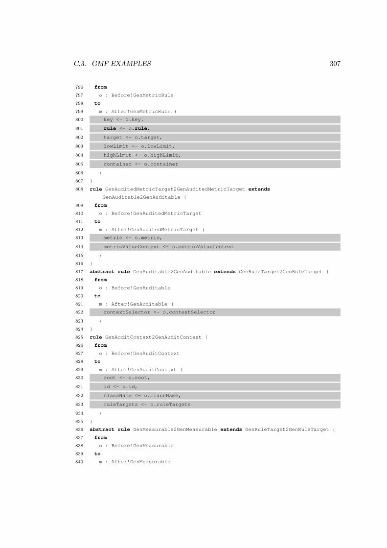
C.3. GMF EXAMPLES 307
796 from
797 o : Before!GenMetricRule
798 to
799 m : After!GenMetricRule (
800 key <- o.key,
801 rule <- o.rule,
802 target <- o.target,
803 lowLimit <- o.lowLimit,
804 highLimit <- o.highLimit,
805 container <- o.container
806 )
807 }
808 rule GenAuditedMetricTarget2GenAuditedMetricTarget extends
GenAuditable2GenAuditable {
809 from
810 o : Before!GenAuditedMetricTarget
811 to
812 m : After!GenAuditedMetricTarget (
813 metric <- o.metric,
814 metricValueContext <- o.metricValueContext
815 )
816 }
817 abstract rule GenAuditable2GenAuditable extends GenRuleTarget2GenRuleTarget {
818 from
819 o : Before!GenAuditable
820 to
821 m : After!GenAuditable (
822 contextSelector <- o.contextSelector
823 )
824 }
825 rule GenAuditContext2GenAuditContext {
826 from
827 o : Before!GenAuditContext
828 to
829 m : After!GenAuditContext (
830 root <- o.root,
831 id <- o.id,
832 className <- o.className,
833 ruleTargets <- o.ruleTargets
834 )
835 }
836 abstract rule GenMeasurable2GenMeasurable extends GenRuleTarget2GenRuleTarget {
837 from
838 o : Before!GenMeasurable
839 to
840 m : After!GenMeasurable

308 APPENDIX C. CO-EVOLUTION EXAMPLES
841 }
842 rule GenExpressionProviderContainer2GenExpressionProviderContainer {
843 from
844 o : Before!GenExpressionProviderContainer
845 to
846 m : After!GenExpressionProviderContainer (
847 expressionsPackageName <- o.expressionsPackageName,
848 abstractExpressionClassName <- o.abstractExpressionClassName,
849 providers <- o.providers
850 )
851 }
852 abstract rule GenExpressionProviderBase2GenExpressionProviderBase {
853 from
854 o : Before!GenExpressionProviderBase
855 to
856 m : After!GenExpressionProviderBase (
857 expressions <- o.expressions
858 )
859 }
860 rule GenJavaExpressionProvider2GenJavaExpressionProvider extends
GenExpressionProviderBase2GenExpressionProviderBase {
861 from
862 o : Before!GenJavaExpressionProvider
863 to
864 m : After!GenJavaExpressionProvider (
865 throwException <- o.throwException,
866 injectExpressionBody <- o.injectExpressionBody
867 )
868 }
869 rule GenExpressionInterpreter2GenExpressionInterpreter extends
GenExpressionProviderBase2GenExpressionProviderBase {
870 from
871 o : Before!GenExpressionInterpreter
872 to
873 m : After!GenExpressionInterpreter (
874 language <- o.language,
875 className <- o.className
876 )
877 }
878 abstract rule GenDomainModelNavigator2GenDomainModelNavigator {
879 from
880 o : Before!GenDomainModelNavigator
881 to
882 m : After!GenDomainModelNavigator (
883 generateDomainModelNavigator <- o.generateDomainModelNavigator,
884 domainContentExtensionID <- o.domainContentExtensionID,

C.3. GMF EXAMPLES 309
885 domainContentExtensionName <- o.domainContentExtensionName,
886 domainContentExtensionPriority <- o.domainContentExtensionPriority,
887 domainContentProviderClassName <- o.domainContentProviderClassName,
888 domainLabelProviderClassName <- o.domainLabelProviderClassName,
889 domainModelElementTesterClassName <- o.domainModelElementTesterClassName,
890 domainNavigatorItemClassName <- o.domainNavigatorItemClassName
891 )
892 }
893 rule GenNavigator2GenNavigator extends
GenDomainModelNavigator2GenDomainModelNavigator {
894 from
895 o : Before!GenNavigator
896 to
897 m : After!GenNavigator (
898 contentExtensionID <- o.contentExtensionID,
899 contentExtensionName <- o.contentExtensionName,
900 contentExtensionPriority <- o.contentExtensionPriority,
901 linkHelperExtensionID <- o.linkHelperExtensionID,
902 sorterExtensionID <- o.sorterExtensionID,
903 actionProviderID <- o.actionProviderID,
904 contentProviderClassName <- o.contentProviderClassName,
905 labelProviderClassName <- o.labelProviderClassName,
906 linkHelperClassName <- o.linkHelperClassName,
907 sorterClassName <- o.sorterClassName,
908 actionProviderClassName <- o.actionProviderClassName,
909 abstractNavigatorItemClassName <- o.abstractNavigatorItemClassName,
910 navigatorGroupClassName <- o.navigatorGroupClassName,
911 navigatorItemClassName <- o.navigatorItemClassName,
912 uriInputTesterClassName <- o.uriInputTesterClassName,
913 packageName <- o.packageName,
914 childReferences <- o.childReferences
915 )
916 }
917 rule GenNavigatorChildReference2GenNavigatorChildReference {
918 from
919 o : Before!GenNavigatorChildReference
920 to
921 m : After!GenNavigatorChildReference (
922 parent <- o.parent,
923 child <- o.child,
924 referenceType <- o.referenceType,
925 groupName <- o.groupName,
926 groupIcon <- o.groupIcon,
927 hideIfEmpty <- o.hideIfEmpty

310 APPENDIX C. CO-EVOLUTION EXAMPLES
928 )
929 }
930 rule GenNavigatorPath2GenNavigatorPath {
931 from
932 o : Before!GenNavigatorPath
933 to
934 m : After!GenNavigatorPath (
935 segments <- o.segments
936 )
937 }
938 rule GenNavigatorPathSegment2GenNavigatorPathSegment {
939 from
940 o : Before!GenNavigatorPathSegment
941 to
942 m : After!GenNavigatorPathSegment (
943 from <- o.from,
944 to <- o.to
945 )
946 }
947 rule GenPropertySheet2GenPropertySheet {
948 from
949 o : Before!GenPropertySheet
950 to
951 m : After!GenPropertySheet (
952 tabs <- o.tabs,
953 packageName <- o.packageName,
954 readOnly <- o.readOnly,
955 needsCaption <- o.needsCaption,
956 labelProviderClassName <- o.labelProviderClassName
957 )
958 }
959 abstract rule GenPropertyTab2GenPropertyTab {
960 from
961 o : Before!GenPropertyTab
962 to
963 m : After!GenPropertyTab (
964 iD <- o.iD,
965 label <- o.label
966 )
967 }
968 rule GenStandardPropertyTab2GenStandardPropertyTab extends
GenPropertyTab2GenPropertyTab {
969 from
970 o : Before!GenStandardPropertyTab
971 to
972 m : After!GenStandardPropertyTab

C.3. GMF EXAMPLES 311
973 }
974 rule GenCustomPropertyTab2GenCustomPropertyTab extends
GenPropertyTab2GenPropertyTab {
975 from
976 o : Before!GenCustomPropertyTab
977 to
978 m : After!GenCustomPropertyTab (
979 className <- o.className,
980 filter <- o.filter
981 )
982 }
983 abstract rule GenPropertyTabFilter2GenPropertyTabFilter {
984 from
985 o : Before!GenPropertyTabFilter
986 to
987 m : After!GenPropertyTabFilter
988 }
989 rule TypeTabFilter2TypeTabFilter extends
GenPropertyTabFilter2GenPropertyTabFilter {
990 from
991 o : Before!TypeTabFilter
992 to
993 m : After!TypeTabFilter (
994 types <- o.types,
995 generatedTypes <- o.generatedTypes
996 )
997 }
998 rule CustomTabFilter2CustomTabFilter extends
GenPropertyTabFilter2GenPropertyTabFilter {
999 from
1000 o : Before!CustomTabFilter
1001 to
1002 m : After!CustomTabFilter (
1003 className <- o.className
1004 )
1005 }
1006 abstract rule GenContributionItem2GenContributionItem {
1007 from
1008 o : Before!GenContributionItem
1009 to
1010 m : After!GenContributionItem
1011 }
1012 rule GenSharedContributionItem2GenSharedContributionItem extends
GenContributionItem2GenContributionItem {
1013 from
1014 o : Before!GenSharedContributionItem
1015 to

312 APPENDIX C. CO-EVOLUTION EXAMPLES
1016 m : After!GenSharedContributionItem (
1017 actualItem <- o.actualItem
1018 )
1019 }
1020 rule GenGroupMarker2GenGroupMarker extends
GenContributionItem2GenContributionItem {
1021 from
1022 o : Before!GenGroupMarker
1023 to
1024 m : After!GenGroupMarker (
1025 groupName <- o.groupName
1026 )
1027 }
1028 rule GenSeparator2GenSeparator extends GenContributionItem2GenContributionItem {
1029 from
1030 o : Before!GenSeparator
1031 to
1032 m : After!GenSeparator (
1033 groupName <- o.groupName
1034 )
1035 }
1036 rule GenActionFactoryContributionItem2GenActionFactoryContributionItem extends
GenContributionItem2GenContributionItem {
1037 from
1038 o : Before!GenActionFactoryContributionItem
1039 to
1040 m : After!GenActionFactoryContributionItem (
1041 name <- o.name
1042 )
1043 }
1044 abstract rule GenContributionManager2GenContributionManager extends
GenContributionItem2GenContributionItem {
1045 from
1046 o : Before!GenContributionManager
1047 to
1048 m : After!GenContributionManager (
1049 iD <- o.iD,
1050 items <- o.items
1051 )
1052 }
1053 rule GenMenuManager2GenMenuManager extends
GenContributionManager2GenContributionManager {
1054 from
1055 o : Before!GenMenuManager
1056 to
1057 m : After!GenMenuManager (
1058 name <- o.name

C.3. GMF EXAMPLES 313
1059 )
1060 }
1061 rule GenToolBarManager2GenToolBarManager extends
GenContributionManager2GenContributionManager {
1062 from
1063 o : Before!GenToolBarManager
1064 to
1065 m : After!GenToolBarManager
1066 }
1067 rule GenApplication2GenApplication {
1068 from
1069 o : Before!GenApplication
1070 to
1071 m : After!GenApplication (
1072 iD <- o.iD,
1073 title <- o.title,
1074 packageName <- o.packageName,
1075 className <- o.className,
1076 perspectiveId <- o.perspectiveId,
1077 supportFiles <- o.supportFiles,
1078 sharedContributionItems <- o.sharedContributionItems,
1079 mainMenu <- o.mainMenu,
1080 mainToolBar <- o.mainToolBar
1081 )
1082 }
Listing C.13: GMF Generator migration in ATL
1 for (genLinkLabel in gen.GenLinkLabel.allInstances) {
2 genLinkLabel.unset(notationViewFactoryClassName)
3 }
4
5 for (genLink in gen.GenLink.allInstances) {
6 genLink.unset(notationViewFactoryClassName)
7 }
8
9 for (genEditorGenerator in gen.GenEditorGenerator.allInstances) {
10 def genContextMenu = gen.GenContextMenu.newInstance()
11 genEditorGenerator.contextMenus.add(genContextMenu)
12
13 genContextMenu.context.add(genEditorGenerator.diagram)
14 genContextMenu.items.add(gen.LoadResourceAction.newInstance())
15
16 for (shortcutName in genContextMenu.diagram.containsShortcutsTo) {
17 genContextMenu.items.add(gen.CreateShorcutAction.newInstance())
18 }

314 APPENDIX C. CO-EVOLUTION EXAMPLES
19 }
20
21 for (genDiagram in gen.GenDiagram) {
22 genDiagram.validationProviderPriority = gen.ProviderPriority#Lowest
23 }
24
25 for (featureLabelModelFacet in gen.FeatureLabelModelFacet) {
26 def viewMethod = featureLabelModelFacet.unset(viewMethod)
27 def editMethod = featureLabelModelFacet.unset(editMethod)
28 featureLabelModelFacet.parser = createOrRetrievePredefinedParser(viewMethod,
editMethod)
29 }
30
31 for (designLabelModelFacet in gen.DesignLabelModelFacet) {
32 designLabelModelFacet.parser = createOrRetrieveExternalParser()
33 }
34
35
36 createOrRetrievePredefinedParser = { viewMethod, editMethod ->
37 if (getPredefinedParser(viewMethod, editMethod) == null) {
38 createOrRetrieveGenParsers().implementations.add(createPredefinedParser(
viewMethod, editMethod))
39 }
40
41 return getPredefinedParser(viewMethod, editMethod)
42 }
43
44 getPredefinedParser = { viewMethod, editMethod ->
45 return gen.PredefinedParser.allInstances.find{ it -> it.viewMethod ==
viewMethod && p.editMethod == editMethod }
46 }
47
48 createPredefinedParser = { viewMethod, editMethod ->
49 def parser = gen.PredefinedParser.newInstance()
50 parser.viewMethod = viewMethod
51 parser.editMethod = editMethod
52 return parser
53 }
54
55 createOrRetrieveExternalParser = {
56 if (gen.ExternalParser.allInstances.size == 0) {
57 createOrRetrieveGenParsers().implementations.add(gen.ExternalParser.
newInstance())
58
59 }
60

C.3. GMF EXAMPLES 315
61 return gen.ExternalParser.first
62 }
63
64 createOrRetrieveGenParsers = {
65 if (gen.GenEditorGenerator.allInstances.first.labelParsers == null) {
66 gen.GenEditorGenerator.allInstances.first.labelParsers = gen.GenParsers.
newInstance()
67 gen.GenEditorGenerator.allInstances.first.labelParsers.extensibleViaService =
true
68 }
69
70 return gen.GenEditorGenerator.allInstances.first.labelParsers
71 }
Listing C.14: GMF Generator migration in Groovy-for-COPE
1 migrate GenLinkLabel {
2 migrated.notationViewFactoryClassName := null;
3 }
4
5 migrate GenLink {
6 migrated.notationViewFactoryClassName := null;
7 }
8
9 migrate GenEditorGenerator {
10 migrated.contextMenus.add(new Migrated!GenContextMenu);
11 migrated.contextMenus.first.context.add(migrated.diagram);
12
13 migrated.contextMenus.first.items.add(new Migrated!LoadResourceAction);
14
15 for (shortcutName in original.diagram.containsShortcutsTo) {
16 migrated.contextMenus.first.items.add(new Migrated!CreateShortcutAction);
17 }
18 }
19
20
21 migrate GenDiagram {
22 migrated.validationProviderPriority := Migrated!ProviderPriority#Lowest;
23 }
24
25 migrate FeatureLabelModelFacet {
26 migrated.parser := createOrRetrievePredefinedParser(migrated.viewMethod,
migrated.editMethod);
27 migrated.viewMethod := null;
28 migrated.editMethod := null;
29 }
30

316 APPENDIX C. CO-EVOLUTION EXAMPLES
31 migrate DesignLabelModelFacet {
32 migrated.parser := createOrRetrieveExternalParser();
33 }
34
35 operation createOrRetrievePredefinedParser(viewMethod : Any, editMethod : Any) :
Migrated!PredefinedParser {
36 if (getPredefinedParser(viewMethod, editMethod).isUndefined()) {
37 createOrRetrieveGenParsers().implementations.add(createPredefinedParser(
viewMethod, editMethod));
38 }
39
40 return getPredefinedParser(viewMethod, editMethod);
41 }
42
43 operation getPredefinedParser(viewMethod : Any, editMethod : Any) : Migrated!
PredefinedParser {
44 return Migrated!PredefinedParser.all.selectOne(p | p.viewMethod = viewMethod
and p.editMethod = editMethod);
45 }
46
47 operation createPredefinedParser(viewMethod : Any, editMethod : Any) : Migrated!
PredefinedParser {
48 var parser := new Migrated!PredefinedParser;
49 parser.viewMethod := viewMethod;
50 parser.editMethod := editMethod;
51 return parser;
52 }
53
54 operation createOrRetrieveExternalParser() : Migrated!ExternalParser {
55 if (Migrated!ExternalParser.all.isEmpty()) {
56 createOrRetrieveGenParsers().implementations.add(new Migrated!ExternalParser)
;
57 }
58
59 return Migrated!ExternalParser.all.first;
60 }
61
62 operation createOrRetrieveGenParsers() : Migrated!GenParsers {
63 if (Migrated!GenEditorGenerator.all.first.labelParsers.isUndefined()) {
64 Migrated!GenEditorGenerator.all.first.labelParsers := new Migrated!GenParsers
;
65 Migrated!GenEditorGenerator.all.first.labelParsers.extensibleViaService :=
true;
66 }
67
68 return Migrated!GenEditorGenerator.all.first.labelParsers;

C.3. GMF EXAMPLES 317
69 }
Listing C.15: GMF Generator migration in Flock


Appendix D
TTC Results
This appendix describes the results of a model migration case submitted to the ToolsTransformation Contest (TTC) 2010 workshop1. Nine solutions were submitted for themigration case and, during the workshop, the solutions were compared and awardeda score by the workshop participants and organisers. The results of the workshopare presented here, and were used for the evaluation of Epsilon Flock described inSection 6.4.
Below, each table presents scores for each of the nine solutions. The first seventables show the score awarded to each tool for the criteria described in Section 6.4:correctness, conciseness, clarity, appropriateness, tool maturity, reproducibility andextensions. The final two tables show the total scores for each tool using an equalweight for each criterion, and using the weights determined by the workshop organisers.Each table shows the mean score (M column), variance between scores (V column), andthe rank of each solution (R column). An x in a cell indicates a conflict of interest (noscore awarded).
1http://www.planet-research20.org/ttc2010/index.php?Itemid=132
319

320A
PP
EN
DIX
D.
TT
CR
ESU
LT
STool 1 2 3 4 5 6 7 8 9 10 11 12 M V R
PETE 0 1 2 1 x 1 1 1 x 2 1 1 1.10 0.29 1COPE 0 1 2 1 x 1 1 0 1 2 1 1 1.00 0.36 2Fujaba 1 x 2 1 0 1 1 1 1 x 1 x 1.00 0.22 2GrGen 0 1 2 1 1 1 x 1 1 2 0 1 1.00 0.36 2
A/J 0 1 1 1 1 1 1 1 1 1 0 1 0.83 0.14 5Mola x 1 x -1 0 1 1 x 1 2 1 1 0.78 0.62 6
Flock 0 x x 1 1 1 0 0 1 1 1 1 0.70 0.21 7GReTL 0 x x 0 1 x 0 1 0 1 0 1 0.44 0.25 8
RSDS 0 1 x -1 0 0 0 0 1 0 1 0 0.18 0.33 9
Table D.1: Correctness scores (in the range -1 to 2).
Tool 1 2 3 4 5 6 7 8 9 10 11 12 M V R
Flock 1 x x 2 2 1 1 1 0 1 2 1 1.20 0.36 1COPE 1 1 1 1 x 1 0 1 1 -1 2 1 0.82 0.51 2GrGen 0 2 1 1 1 0 x 1 0 1 1 1 0.82 0.33 2Fujaba 1 x 1 0 -1 0 0 0 -1 x 1 x 0.11 0.54 4
Mola x 0 x -2 0 0 0 x -1 1 1 1 0.00 0.89 5A/J -1 -1 1 0 -1 0 0 0 0 -1 0 0 -0.25 0.35 6
PETE -2 -1 1 1 x -1 -1 0 x 0 1 -1 -0.30 1.01 7GReTL -1 x x 1 -1 x 0 0 -1 -1 0 0 -0.33 0.56 8
RSDS 0 -1 x -1 -1 0 0 -1 -1 0 -1 0 -0.55 0.25 9
Table D.2: Conciseness scores (in the range -2 to 2).

321
Tool 1 2 3 4 5 6 7 8 9 10 11 12 M V R
Flock 1 x x 1 1 0 1 1 1 1 1 1 0.90 0.09 1COPE 1 1 1 0 x 1 0 0 1 1 1 1 0.73 0.20 2GrGen 0 0 0 1 0 1 x 0 1 1 0 1 0.45 0.25 3
Mola x 1 x 1 0 1 -1 x 0 1 0 1 0.44 0.47 4Fujaba 1 x 0 1 0 0 0 0 0 x 1 x 0.33 0.22 5
A/J -1 0 1 0 1 1 0 0 0 1 0 0 0.25 0.35 6GReTL 0 x x 0 0 x 1 0 0 0 0 0 0.15 0.10 7PETE 0 1 0 0 x 0 0 0 x 0 0 0 0.10 0.09 8RSDS -1 1 x 0 0 0 -1 -1 0 -1 1 0 -0.18 0.51 9
Table D.3: Clarity scores (in the range -1 to 1).
Tool 1 2 3 4 5 6 7 8 9 10 11 12 M V R
Flock 1 x x 2 2 1 2 1 1 2 2 2 1.60 0.24 1COPE 2 2 2 1 x 2 0 1 2 2 1 2 1.55 0.43 2GrGen 0 1 1 1 0 1 x 1 1 1 0 1 0.73 0.20 3
Mola x 1 x 0 0 1 0 x 0 1 1 2 0.67 0.44 4Fujaba 1 x 1 0 0 1 0 0 0 x 0 x 0.33 0.22 5
GReTL 0 x x 0 0 x 1 1 0 0 0 0 0.30 0.18 6PETE -1 1 1 0 x 0 0 0 x 0 0 1 0.20 0.36 7
A/J 0 1 0 0 0 0 0 -1 0 1 0 1 0.17 0.31 8RSDS 0 0 x -1 0 1 0 0 0 0 0 1 0.09 0.26 9
Table D.4: Appropriateness scores (in the range -2 to 2).

322A
PP
EN
DIX
D.
TT
CR
ESU
LT
STool 1 2 3 4 5 6 7 8 9 10 11 12 M V R
Fujaba 1 x 1 1 1 1 1 1 1 x 0 x 0.89 0.10 1GrGen 0 0 1 1 1 0 x 0 0 1 1 1 0.55 0.25 2Flock 0 x x 0 0 1 0 0 1 1 0 1 0.40 0.24 3Mola x 1 x 0 -1 1 0 x 1 0 0 1 0.33 0.44 4
COPE 0 0 1 0 x 0 0 -1 0 0 1 1 0.18 0.33 5PETE -1 0 1 0 x 1 0 -1 x 0 0 0 0.00 0.40 6
GReTL -1 x x -1 0 x 0 -1 0 0 0 0 -0.28 0.23 7A/J -1 -1 -1 -1 -1 0 0 0 0 -1 0 -1 -0.58 0.24 8
RSDS -1 -1 x -1 -1 -1 -1 -1 -1 -1 0 0 -0.82 0.15 9
Table D.5: Tool maturity scores (in the range -1 to 1).
Tool 1 2 3 4 5 6 7 8 9 10 11 12 M V R
A/J 1 1 1 1 1 1 1 1 1 1 1 1 1 0.00 1COPE 1 1 1 1 x 1 1 1 1 1 1 1 1 0.00 1Flock 1 x x 1 1 1 1 1 1 1 1 1 1 0.00 1Fujaba 1 x 1 1 1 1 1 1 1 x 1 x 1 0.00 1
GReTL 1 x x 1 1 x 1 1 1 1 1 1 1 0.00 1GrGen 1 1 1 1 1 1 x 1 1 1 1 1 1 0.00 1
Mola x 1 x 1 1 1 1 x 1 1 1 1 1 0.00 1PETE 1 1 1 1 x 1 1 1 x 1 1 1 1 0.00 1RSDS 0 0 x 0 0 0 0 0 0 0 0 0 0 0.00 9
Table D.6: Reproducibility scores (in the range 0 to 1).

323
Tool 1 2 3 4 5 6 7 8 9 10 11 12 M V R
Flock 2 x x 2 2 1 2 2 2 2 2 1 1.80 0.16 1Fujaba 1 x 2 2 2 2 2 1 1 x 1 x 1.56 0.25 2
A/J 1 2 2 2 0 2 2 2 2 1 0 2 1.50 0.58 3COPE 1 1 1 1 x 1 1 1 1 1 1 1 1.00 0.00 4
GReTL 1 x x 1 1 x 1 1 1 1 1 1 1.00 0.00 4GrGen 1 1 1 1 2 1 x 1 1 1 0 1 1.00 0.18 4PETE 1 1 1 1 x 1 1 1 x 1 0 0 0.80 0.16 7
Mola x 0 x 0 0 0 0 x 0 0 1 0 0.11 0.10 8RSDS 0 0 x 0 0 0 0 0 0 0 0 0 0.00 0.00 9
Table D.7: Extensions scores (in the range 0 to 2).
Tool 1 2 3 4 5 6 7 8 9 10 11 12 M V R
Flock 6 x x 9 9 6 7 6 7 9 9 8 7.60 1.64 1COPE 6 7 9 5 x 7 3 3 7 6 8 8 6.27 3.47 2GrGen 2 6 7 7 6 5 x 5 5 8 4 7 5.64 2.60 3Fujaba 7 x 8 6 3 6 5 4 3 x 5 x 5.22 2.62 4
Mola x 5 x -1 0 5 2 x 2 6 5 7 3.44 6.91 5A/J -1 3 5 3 1 5 4 3 4 3 2 4 3.00 2.67 6
PETE -2 4 7 4 x 3 2 2 x 4 3 2 2.90 4.69 7GReTL 0 x x 2 2 x 4 x 1 6 2 3 2.50 3.00 8
RSDS -2 0 x -4 -2 0 -2 -3 -1 -2 1 1 -1.27 2.38 9
Table D.8: Total (equally weighted) scores (in the range -7 to 11).

324A
PP
EN
DIX
D.
TT
CR
ESU
LT
S
Tool 1 2 3 4 5 6 7 8 9 10 11 12 M V R
Flock 17 x x 28 28 20 20 17 23 29 28 26 23.60 20.64 1COPE 17 22 31 16 x 22 10 7 22 21 26 26 20.00 45.45 2GrGen 5 19 25 23 20 16 x 16 16 28 12 23 18.45 38.07 3Fujaba 23 x 28 20 9 20 17 14 11 x 16 x 17.56 31.36 4
Mola x 17 x -6 -2 17 7 x 8 21 16 23 11.22 91.51 5PETE -8 13 25 13 x 11 7 6 x 15 10 7 9.90 62.69 6
A/J -5 9 15 9 3 16 13 10 13 9 5 12 9.08 31.24 7GReTL -2 x x 4 7 x 11 9 2 12 5 10 6.44 18.91 8
RSDS -7 1 x -15 -7 -1 -7 -10 -2 -7 5 3 -4.27 32.74 9
Table D.9: Total (weighted) scores (in the range -24 to 37).

Bibliography
[Ackoff 1962] R.L. Ackoff. Scientific Method: Optimizing Applied Research Decisions.John Wiley and Sons, New York, 1962.
[Aizenbud-Reshef et al. 2005] N. Aizenbud-Reshef, R.F. Paige, J. Rubin, Y. Shaham-Gafni, and D.S. Kolovos. Operational semantics for traceability. In Proc. Work-shop on Traceability, co-located with the European Conference on Model-DrivenArchitecture (ECMDA), pages 8–14, 2005.
[Alexander et al. 1977] C. Alexander, S. Ishikawa, and M. Silverstein. A PatternLanguage: Towns, Buildings, Construction (Center for Environmental StructureSeries). Oxford University Press, New York, 1977.
[Alvarez et al. 2001] J. Alvarez, A. Evans, and P. Sammut. MML and the metamodelarchitecture. In Proc. Workshop on Transformation in UML, co-located with theEuropean Joint Conferences on Theory and Practice of Software (ETAPS), 2001.
[Amyot et al. 2006] D. Amyot, H. Farah, and J.-F. Roy. Evaluation of developmenttools for domain-specific modeling languages. In R. Gotzhein and R. Reed, editors,System Analysis and Modeling: Language Profiles, volume 4320 of Lecture Notesin Computer Science, pages 183–197. Springer, Heidelberg, 2006.
[Apostel 1960] L. Apostel. Towards the formal study of models in the non-formalsciences. Synthese, 12(2):125–161, 1960.
[Arendt et al. 2009] T. Arendt, F. Mantz, L. Schneider, and G. Taentzer. Modelrefactoring in Eclipse by LTK, EWL, and EMF Refactor: A case study. In Proc.Joint Model-Driven Software Evolution and Model Co-evolution and ConsistencyManagement (MoDSE-MCCM) Workshop, co-located with the International Con-ference on Model-Driven Engineering Languages and Systems (MoDELS), 2009.
[Backus 1978] J. Backus. The history of FORTRAN I, II and III. History of Pro-gramming Languages, 1:165–180, 1978.
[Balazinska et al. 2000] M. Balazinska, E. Merlo, M. Dagenais, B. Lague, and K. Kon-togiannis. Advanced clone-analysis to support object-oriented system refactoring.In Proc. Working Conference on Reverse Engineering (WCRE), pages 98–107.IEEE Computer Society, 2000.
325
326 BIBLIOGRAPHY
[Banerjee et al. 1987] J. Banerjee, W. Kim, H. Kim, and H.F. Korth. Semantics andimplementation of schema evolution in object-oriented databases. In U. Dayaland I.L. Traiger, editors, Proc. Special Interest Group on Management of Data(SIGMOD) Conference, pages 311–322. ACM Press, 1987.
[Barry 2006] B. Barry. A view of 20th and 21st century software engineering. In L.J.Osterweil, H.D. Rombach, and M.L. Soffa, editors, Proc. International conferenceon Software Engineering (ICSE), pages 12–29. ACM, 2006.
[Beattie et al. 2007] B.R. Beattie, C.R. Taylor, and M.J. Watts. The Economics ofProduction. Krieger Publishing Company, 2nd edition, 2007.
[Beck & Cunningham 1989] K. Beck and W. Cunningham. Constructing abstractionsfor object-oriented applications. Journal of Object Oriented Programming, 2, 1989.
[Bezivin & Gerbe 2001] J. Bezivin and O. Gerbe. Towards a precise definition of theOMG/MDA framework. In Proc. International Conference on Automated SoftwareEngineering (ASE), pages 273–280. IEEE Computer Society, 2001.
[Bezivin 2005] J. Bezivin. On the unification power of models. Software and SystemModeling, 4(2):171–188, 2005.
[Biermann et al. 2006] E. Biermann, K. Ehrig, C. Kohler, G. Kuhns, G. Taentzer, andE. Weiss. EMF model refactoring based on graph transformation concepts. Elec-tronic Communications of the European Association for the Study of Science andTechnology [online], 3, 2006. Available at http://eceasst.cs.tu-berlin.de/index.php/eceasst/article/view/34 [Accessed 2 November 2010].
[Bloch 2005] J. Bloch. How to design a good API and why it matters [online]. Keynoteaddress to the LCSD Workshop at OOPSLA, October 2005, San Diego, UnitedStates of America. Available at: http://lcsd05.cs.tamu.edu/slides/keynote.pdf [Accessed 2 November 2010], 2005.
[Bohner 2002] S.A. Bohner. Software change impacts - an evolving perspective. InProc. International Conference on Software Maintenance (ICSM), pages 263–272.IEEE Computer Society, 2002.
[Bosch 1998] J. Bosch. Design patterns as language constructs. Journal of ObjectOriented Programming, 11(2):18–32, 1998.
[Briand et al. 2003] L.C. Briand, Y. Labiche, and L. O’Sullivan. Impact analysis andchange management of uml models. In Proc. International Conference on SoftwareMaintenance (ICSM), pages 256–265. IEEE Computer Society, 2003.
[Brooks Jr. 1987] F.P. Brooks Jr. No silver bullet - essence and accidents of softwareengineering. IEEE Computer, 20(4):10–19, 1987.

BIBLIOGRAPHY 327
[Brooks Jr. 1995] F.P. Brooks Jr. The mythical man-month. Addison-Wesley Long-man Publishing Co., Inc., Boston, Massachusetts, 25th anniversary edition, 1995.
[Brown et al. 1998] W.J. Brown, R.C. Malveau, H.W. McCormick III, and T.J. Mow-bray. Anti Patterns. Wiley, New York, 1998.
[Brun & Pierantonio 2008] C. Brun and A. Pierantonio. Model differences in theEclipse Modelling Framework. Upgrade, 9(2):29–34, 2008.
[Cervelle et al. 2006] J. Cervelle, R. Forax, and G. Roussel. Tatoo: an innovativeparser generator. In Ralf Gitzel, Markus Aleksy, and Martin Schader, editors,Proc. International Symposium on Principles and Practice of Programming in Java(PPPJ), volume 178 of ACM International Conference Proceeding Series, pages13–20. ACM, 2006.
[Chen & Chou 1999] J.Y.J. Chen and S.C. Chou. Consistency management in aprocess environment. Systems and Software, 47(2-3):105–110, 1999.
[Cicchetti et al. 2008] A. Cicchetti, D. Di Ruscio, R. Eramo, and A. Pierantonio. Au-tomating co-evolution in model-driven engineering. In Proc. International IEEEEnterprise Distributed Object Computing Conference (EDOC), pages 222–231.IEEE Computer Society, 2008.
[Cicchetti 2008] A. Cicchetti. Difference Representation and Conflict Managementin Model-Driven Engineering. PhD thesis, Universita’ degli Studi dell’Aquila,L’Aquila, Italy, 2008.
[Clark et al. 2008] T. Clark, P. Sammut, and J. Willians. Superlanguages: DevelopingLanguages and Applications with XMF [online]. Ceteva, Sheffield, 2008. Availableat: http://itcentre.tvu.ac.uk/˜clark/Papers/Superlanguages.pdf [Accessed 02 November 2010].
[Cleland-Huang et al. 2003] J. Cleland-Huang, C.K. Chang, and M. Christensen.Event-based traceability for managing evolutionary change. IEEE Transactionson Software Engineering, 29(9):796–810, 2003.
[Costa & Silva 2007] M. Costa and A.R. da Silva. RT-MDD framework – a prac-tical approach. In Proc. Workshop on Traceability, co-located with the EuropeanConference on Model-Driven Architecture (ECMDA), pages 17–26, 2007.
[Czarnecki & Helsen 2006] K. Czarnecki and S. Helsen. Feature-based survey of modeltransformation approaches. IBM Systems Journal, 45(3):621–646, 2006.
[de Lara & Guerra 2010] J. de Lara and E. Guerra. Generic meta-modelling with con-cepts, templates and mixin layers. In D.C. Petriu, N. Rouquette, and Ø. Haugen,editors, Proc. International Conference on Model Driven Engineering Languagesand System (MoDELS), Part I, volume 6394 of Lecture Notes in Computer Sci-ence, pages 16–30. Springer, 2010.

328 BIBLIOGRAPHY
[Deursen et al. 2000] A. van Deursen, P. Klint, and J. Visser. Domain-Specific Lan-guages: An annotated bibliography. Special Interest Group on Programming Lan-guages (SIGPLAN) Notices, 35(6):26–36, 2000.
[Deursen et al. 2007] A. van Deursen, E. Visser, and J. Warmer. Model-driven soft-ware evolution: A research agenda. In Proc. Workshop on Model-Driven SoftwareEvolution, co-located with the European Conference on Software Maintenance andReengineering (CSMR), pages 41–49, 2007.
[Dig & Johnson 2006a] D. Dig and R. Johnson. Automated upgrading of component-based applications. In P.L. Tarr and W.R. Cook, editors, Companion to the ACMSIGPLAN Conference on Object-Oriented Programming, Systems, Languages, andApplications (OOPSLA), pages 675–676, 2006.
[Dig & Johnson 2006b] D. Dig and R. Johnson. How do APIs evolve? A story ofrefactoring. Journal of Software Maintenance and Evolution, 18(2):83–107, 2006.
[Dig et al. 2006] D. Dig, C. Comertoglu, D. Marinov, and R. Johnson. Automateddetection of refactorings in evolving components. In D. Thomas, editor, Proc.European Conference on Object-Oriented Programming (ECOOP), volume 4067of Lecture Notes in Computer Science, pages 404–428. Springer, 2006.
[Dig et al. 2007] D. Dig, K. Manzoor, R. Johnson, and T.N. Nguyen. Refactoring-aware configuration management for object-oriented programs. In Proc. Interna-tional Conference on Software Engineering (ICSE), pages 427–436. IEEE Com-puter Society, 2007.
[Dig 2007] D. Dig. Automated Upgrading of Component-Based Applications. PhDthesis, University of Illinois at Urbana-Champaign, USA, 2007.
[Drivalos et al. 2008] N. Drivalos, R.F. Paige, K.J. Fernandes, and D.S. Kolovos.Towards rigorously defined model-to-model traceability. In Proc. Workshop onTraceability, co-located with the European Conference on Model Driven Architec-ture (ECMDA), 2008.
[Ducasse et al. 1999] S. Ducasse, M. Rieger, and S. Demeyer. A language independentapproach for detecting duplicated code. In Proc. International Conference onSoftware Maintenance (ICSM), pages 109–118. IEEE Computer Society, 1999.
[Edelweiss & Moreira 2005] N. Edelweiss and A.F. Moreira. Temporal and version-ing model for schema evolution in object-oriented databases. Data & KnowledgeEngineering, 53(2):99–128, 2005.
[Elaasar & Briand 2004] M. Elaasar and L.C. Briand. An overview of UML con-sistency management. Technical Report SCE-04-18, Carleton University, August2004.

BIBLIOGRAPHY 329
[Elmasri & Navathe 2006] R. Elmasri and S.B. Navathe. Fundamentals of DatabaseSystems. Addison-Wesley Longman, Boston, Massachusetts, 5th edition, 2006.
[Erlikh 2000] L. Erlikh. Leveraging legacy system dollars for e-business. IT Profes-sional, 2(3):17–23, 2000.
[Evans 2004] E. Evans. Domain-Driven Design: Tacking Complexity In the Heart ofSoftware. Addison-Wesley, Boston, Massachusetts, 2004.
[Feathers 2004] M.C. Feathers. Working Effectively with Legacy Code. Prentice Hall,Upper Saddle River, New Jersey, 2004.
[Ferrandina et al. 1995] F. Ferrandina, T. Meyer, R. Zicari, G. Ferran, and J. Madec.Schema and database evolution in the O2 object database system. In U. Dayal,P.M.D. Gray, and S. Nishio, editors, Proc. International Conference on Very LargeData Bases (VLDB), pages 170–181. Morgan Kaufmann, 1995.
[Fowler 1999] M. Fowler. Refactoring: improving the design of existing code. Addison-Wesley, Upper Saddle River, New Jersey, 1999.
[Fowler 2002] M. Fowler. Patterns of Enterprise Application Architecture. Addison-Wesley, Boston, Massachusetts, 2002.
[Fowler 2010] M. Fowler. Domain Specific Languages. Addison-Wesley Professional,Boston, Massachusetts, 2010.
[Frankel 2002] D. Frankel. Model Driven Architecture: Applying MDA to EnterpriseComputing. John Wiley & Sons Inc., New York, 2002.
[Fritzsche et al. 2008] M. Fritzsche, J. Johannes, S. Zschaler, A. Zherebtsov, andA. Terekhov. Application of tracing techniques in model-driven performance en-gineering. In Proc.Traceability Workshop, co-located with the European Confer-ence on Model-Driven Architecture - Foundations and Applications (ECMDA-FA),pages 111–120, 2008.
[Fuhrer et al. 2007] R.M. Fuhrer, A. Kiezun, and M. Keller. Refactoring in the EclipseJDT: Past, present, and future. In Proc. Workshop on Refactoring Tools (WRT),co-located with European Conference on Object-Oriented Programming (ECOOP),2007.
[Gamma et al. 1995] E. Gamma, R. Helm, R. Johnson, and J. Vlissides. Designpatterns: elements of reusable object-oriented software. Addison-Wesley, Reading,Massachusetts, 1995.
[Garces et al. 2009] K. Garces, F. Jouault, P. Cointe, and J. Bezivin. Managing modeladaptation by precise detection of metamodel changes. In R.F. Paige, A. Hartman,and A. Rensink, editors, Proc. European Conference on Model Driven Architecture- Foundations and Applications (ECMDA-FA), volume 5562 of Lecture Notes inComputer Science, pages 34–49. Springer, 2009.

330 BIBLIOGRAPHY
[Geiß & Kroll 2007] R. Geiß and M. Kroll. GrGen.NET: A fast, expressive, andgeneral purpose graph rewrite tool. In A. Schurr, M. Nagl, and A. Zundorf,editors, Proc. International Symposium on Applications of Graph Transformationswith Industrial Relevance (AGTIVE), Revised Selected and Invited Papers, volume5088 of Lecture Notes in Computer Science, pages 568–569. Springer, 2007.
[Gosling et al. 2005] J. Gosling, B. Joy, G. Steele, and G. Bracha. The JavaTM
Language Specification. Addison-Wesley, Boston, Massachusetts, 2005.
[Graham 1993] P. Graham. On Lisp: Advanced Techniques for Common Lisp.Prentice-Hall, Upper Saddle River, New Jersey, 1993.
[Greenfield et al. 2004] J. Greenfield, K. Short, S. Cook, and S. Kent. Software Fac-tories: Assembling Applications with Patterns, Models, Frameworks, and Tools.John Wiley & Sons Inc., New York, 2004.
[Gronback 2009] R.C. Gronback. Eclipse Modeling Project: A Domain-Specific Lan-guage (DSL) Toolkit. Addison-Wesley Professional, Boston, Massachusetts, 2009.
[Gruschko et al. 2007] B. Gruschko, D.S. Kolovos, and R.F. Paige. Towards synchro-nizing models with evolving metamodels. In Proc. Workshop on Model-DrivenSoftware Evolution, co-located with the European Conference on Software Mainte-nance and Reengineering (CSMR), 2007.
[Guerrini et al. 2005] G. Guerrini, M. Mesiti, and D. Rossi. Impact of XML schemaevolution on valid documents. In A. Bonifati and D. Lee, editors, Proc. Inter-national Workshop on Web Information and Data Management (WIDM), pages39–44. ACM, 2005.
[Halstead 1977] M.H. Halstead. Elements of Software Science. Elsevier Science Inc.,New York, 1977.
[Hearnden et al. 2006] D. Hearnden, M. Lawley, and K. Raymond. Incrementalmodel transformation for the evolution of model-driven systems. In O. Nierstrasz,J. Whittle, D. Harel, and G. Reggio, editors, Proc. International Conference onModel Driven Engineering Languages and Systems (MoDELS), volume 4199 ofLecture Notes in Computer Science, pages 321–335. Springer, 2006.
[Heidenreich et al. 2009] F. Heidenreich, J. Johannes, S. Karol, M. Seifert, andC. Wende. Derivation and refinement of textual syntax for models. In R.F. Paige,A. Hartman, and A. Rensink, editors, Proc. European Conference on Model-DrivenArchitecture - Foundations and Applications (ECMDA-FA), volume 5562 of Lec-ture Notes in Computer Science, pages 114–129. Springer, 2009.
[Henriksson et al. 2008] J. Henriksson, F. Heidenreich, J. Johannes, S. Zschaler, andU. Aßmann. Extending grammars and metamodels for reuse: the Reuseware ap-proach. IET Software, 2(3):165–184, 2008.

BIBLIOGRAPHY 331
[Herrmannsdoerfer et al. 2008a] M. Herrmannsdoerfer, S. Benz, and E. Juergens.Automatability of coupled evolution of metamodels and models in practice. InK. Czarnecki, I. Ober, J. Bruel, A. Uhl, and M. Volter, editors, Proc. InternationalConference on Model Driven Engineering Languages and Systems (MoDELS), vol-ume 5301 of Lecture Notes in Computer Science, pages 645–659. Springer, 2008.
[Herrmannsdoerfer et al. 2008b] M. Herrmannsdoerfer, S. Benz, and E. Juergens.COPE: A language for the coupled evolution of metamodels and models. InProc. International Workshop on Model Co-Evolution and Consistency Manage-ment (MCCM), co-located with the International Conference on Model-Driven En-gineering Languages and Systems (MoDELS), 2008.
[Herrmannsdoerfer et al. 2009a] M. Herrmannsdoerfer, S. Benz, and E. Juer-gens. COPE - automating coupled evolution of metamodels and models. InS. Drossopoulou, editor, Proc. European Conference on Object-Oriented Program-ming (ECOOP), volume 5653 of Lecture Notes in Computer Science, pages 52–76.Springer, 2009.
[Herrmannsdoerfer et al. 2009b] M. Herrmannsdoerfer, D. Ratiu, and G. Wachsmuth.Language evolution in practice. In M. van den Brand, D. Gasevic, and J. Gray,editors, Proc. International Conference on Software Language Engineering (SLE),Revised Selected Papers, volume 5696 of Lecture Notes in Computer Science, pages3–22. Springer, 2009.
[Hussey & Paternostro 2006] K. Hussey and M. Paternostro. Advanced features ofEMF. Tutorial at EclipseCon 2006, California, USA. [Accessed 02 November 2010]Available at: http://www.eclipsecon.org/2006/Sub.do?id=171, 2006.
[ISO/IEC 1996] Information Technology ISO/IEC. Syntactic metalanguage – Ex-tended BNF. ISO 14977:1996 International Standard, 1996.
[ISO/IEC 2002] Information Technology ISO/IEC. Z Formal Specification Notation– Syntax, Type System and Semantics. ISO 13568:2002 International Standard,2002.
[Jackson 1995] M. Jackson. Software Requirements and Specifications: A Lexicon ofPractice, Principles and Prejudices. ACM Press, New York, 1995.
[Jouault & Kurtev 2005] F. Jouault and I. Kurtev. Transforming models with ATL. InJ-M. Bruel, editor, Proc. Satellite Events at the International Conference on ModelDriven Engineering Languages and Systems (MoDELS), International Workshops,Doctoral Symposium, Educators Symposium, Revised Selected Papers, volume 3844of Lecture Notes in Computer Science, pages 128–138. Springer, 2005.
[Jouault 2005] F. Jouault. Loosely coupled traceability for ATL. In Proc. Work-shop on Traceability, co-located with the European Conference on Model-DrivenArchitecture (ECMDA), 2005.

332 BIBLIOGRAPHY
[Jurack & Mantz 2010] S. Jurack and F. Mantz. Towards metamodel evolution ofEMF models with Henshin. In Proc. Models and Evolution Workshop, co-locatedwith the International Conference on Model Driven Engineering Languages andSystems (MoDELS), 2010.
[Kalnins et al. 2005] A. Kalnins, J. Barzdins, and E. Celms. Model transformationlanguage MOLA. In U. Aßmann, M. Aksit, and A. Rensink, editors, Proc. ModelDriven Architecture, European MDA Workshops: Foundations and Applications,MDAFA 2003 and MDAFA 2004, Revised Selected Papers, volume 3599 of LectureNotes in Computer Science, pages 62–76. Springer, 2005.
[Kataoka et al. 2001] Y. Kataoka, M.D. Ernst, W.G. Griswold, and D. Notkin. Au-tomated support for program refactoring using invariants. In Proc. InternationalConference on Software Maintenance (ICSM), pages 736–743. IEEE ComputerSociety, 2001.
[Kelly & Tolvanen 2008] S. Kelly and J.P. Tolvanen. Domain-Specific Modelling.Wiley and IEEE Computer Society, 2008.
[Kelly 1999] T.P. Kelly. Arguing Safety – A Systematic Approach to Safety CaseManagement. PhD thesis, University of York, United Kingdom, 1999.
[Kerievsky 2004] J. Kerievsky. Refactoring to Patterns. Pearson Higher Education,2004.
[Kleppe et al. 2003] A.G. Kleppe, J. Warmer, and W. Bast. MDA Explained: TheModel Driven Architecture: Practice and Promise. Addison-Wesley Longman Pub-lishing Co. Inc., Boston, Massachusetts, 2003.
[Klint et al. 2003] P. Klint, R. Lammel, and C. Verhoef. Towards an engineering disci-pline for grammarware. ACM Transactions on Software Engineering Methodology,14(3):331–380, 2003.
[Kolovos et al. 2006] D.S. Kolovos, R.F. Paige, and F.A. Polack. The Epsilon ObjectLanguage (EOL). In A. Rensink and J. Warmer, editors, Proc. European Confer-ence on Model-Driven Architecture - Foundations and Applications (ECMDA-FA),volume 4066 of Lecture Notes in Computer Science, pages 128–142. Springer, 2006.
[Kolovos et al. 2007] D.S. Kolovos, R.F. Paige, F.A.C. Polack, and L.M. Rose. Updatetransformations in the small with the Epsilon Wizard Language. Journal of ObjectTechnology, 6(9):53–69, 2007.
[Kolovos et al. 2008a] D.S. Kolovos, R.F. Paige, and F.A.C. Polack. The grand chal-lenge of scalability for model driven engineering. In M.R. Chaudron, editor, Modelsin Software Engineering: Workshops and Symposia at MoDELS 2008, Reports andRevised Selected Papers, volume 5421 of Lecture Notes in Computer Science, pages48–53. Springer-Verlag, 2008.
BIBLIOGRAPHY 333
[Kolovos et al. 2008b] D.S. Kolovos, R.F. Paige, and F.A.C Polack. The EpsilonTransformation Language. In A. Vallecillo, J. Gray, and A. Pierantonio, editors,Proc. International Conference on the Theory and Practice of Model Transforma-tions (ICMT), volume 5063 of Lecture Notes in Computer Science, pages 46–60.Springer, 2008.
[Kolovos et al. 2009] D.S. Kolovos, R.F. Paige, and F.A.C. Polack. On the evolutionof OCL for capturing structural constraints in modelling languages. In J. Abrialand U. Glasser, editors, Rigorous Methods for Software Construction and Analysis,volume 5115 of Lecture Notes in Computer Science, pages 204–218. Springer, 2009.
[Kolovos et al. 2010] D.S. Kolovos, L.M. Rose, S. bin Abid, R.F. Paige, F.A.C. Polack,and G. Botterweck. Taming EMF and GMF using model transformation. In D.C.Petriu, N. Rouquette, and Ø. Haugen, editors, Proc. International Conference onModel Driven Engineering Languages and System (MoDELS), Part I, volume 6394of Lecture Notes in Computer Science, pages 211–225. Springer, 2010.
[Kolovos 2009] D.S. Kolovos. An Extensible Platform for Specification of IntegratedLanguages for Model Management. PhD thesis, University of York, United King-dom, 2009.
[Kramer 2001] D. Kramer. XEM: XML Evolution Management. Master’s thesis,Worcester Polytechnic Institute, MA, USA, 2001.
[Kurtev 2004] I. Kurtev. Adaptability of Model Transformations. PhD thesis, Uni-versity of Twente, Netherlands, 2004.
[Lago et al. 2009] P. Lago, H. Muccini, and H. van Vliet. A scoped approach totraceability management. Systems and Software, 82(1):168–182, 2009.
[Lammel & Verhoef 2001] R. Lammel and C. Verhoef. Semi-automatic grammarrecovery. Software - Practice and Experience, 31(15):1395–1438, 2001.
[Lammel 2001] R. Lammel. Grammar adaptation. In J.N. Oliveira and P. Zave,editors, Proc. Formal Methods for Increasing Software Productivity (FME), Inter-national Symposium of Formal Methods Europe, volume 2021 of Lecture Notes inComputer Science, pages 550–570. Springer, 2001.
[Lammel 2002] R. Lammel. Towards generic refactoring. In B. Fischer and E. Visser,editors, Proc. ACM SIGPLAN Workshop on Rule-Based Programming, pages 15–28. ACM, 2002.
[Lehman 1969] M.M. Lehman. The programming process. Technical report, IBMResearch Report RC 2722, 1969.
[Lerner 2000] B.S. Lerner. A model for compound type changes encountered in schemaevolution. ACM Transactions on Database Systems, 25(1):83–127, 2000.

334 BIBLIOGRAPHY
[Mader et al. 2008] P. Mader, O. Gotel, and I. Philippow. Rule-based maintenanceof post-requirements traceability relations. In Proc. IEEE International Require-ments Engineering Conference (RE), pages 23–32. IEEE Computer Society, 2008.
[Martin & Martin 2006] R.C. Martin and M. Martin. Agile Principles, Patterns, andPractices in C#. Prentice Hall, Upper Saddle River, NJ, USA, 2006.
[McCarthy 1978] J. McCarthy. History of Lisp. History of Programming Languages,1:217–223, 1978.
[McNeile 2003] A. McNeile. MDA: The vision with the hole? [online]. Metamaxim Ltd,2003. [Accessed 02 November 2010] Available at: http://www.metamaxim.com/download/documents/MDAv1.pdf.
[Mellor & Balcer 2002] S.J. Mellor and M. Balcer. Executable UML: A Foundation forModel-Driven Architectures. Addison-Wesley Longman, Boston, Massachusetts,2002.
[Melnik 2004] S. Melnik. Generic Model Management: Concepts and Algorithms.PhD thesis, University of Leipzig, Germany, 2004.
[Mendez et al. 2010] D. Mendez, A. Etien, A. Muller, and R. Casallas. Towardstransformation migration after metamodel evolution. In Proc. Models and Evo-lution Workshop, co-located with the International Conference on Model DrivenEngineering Languages and Systems (MoDELS), 2010.
[Mens & Demeyer 2007] T. Mens and S. Demeyer. Software Evolution. Springer-Verlag, Berlin, 2007.
[Mens & Tourwe 2004] T. Mens and T. Tourwe. A survey of software refactoring.IEEE Transactions on Software Engineering, 30(2):126–139, 2004.
[Mens et al. 2007] T. Mens, G. Taentzer, and D. Muller. Challenges in model refac-toring. In Proc. Workshop on Object-Oriented Reengineering, co-located with theEuropean Conference on Object-Oriented Programming (ECOOP), 2007.
[Merriam-Webster 2010] Merriam-Webster. Definition of Nuclear Family [online].[Accessed 02 November 2010] Available at: http://www.merriam-webster.com/dictionary/nuclear%20family, 2010.
[Moad 1990] J. Moad. Maintaining the competitive edge. Datamation, 36(4):61–66,1990.
[Moha et al. 2009] N. Moha, V. Mahe, O. Barais, and J.M. Jezequel. Generic modelrefactorings. In A. Schurr and B. Selic, editors, Proc. International Conferenceon Model Driven Engineering Languages and Systems (MoDELS), volume 5795 ofLecture Notes in Computer Science, pages 628–643. Springer, 2009.

BIBLIOGRAPHY 335
[Muller & Hassenforder 2005] P. Muller and M. Hassenforder. HUTN as a Bridgebetween ModelWare and GrammarWare. In Proc. Workshop in Software Mod-elling Engineering, co-located with the International Conference on Model DrivenEngineering Languages and Systems (MoDELS), 2005.
[Nentwich et al. 2003] C. Nentwich, W. Emmerich, A. Finkelstein, and E. Ellmer.Flexible consistency checking. ACM Transactions on Software Engineering andMethodology, 12(1):28–63, 2003.
[Nguyen et al. 2005] T.N. Nguyen, C. Thao, and E.V. Munson. On product version-ing for hypertexts. In Proc. International Workshop on Software ConfigurationManagement (SCM), pages 113–132. ACM, 2005.
[Nickel et al. 2000] U. Nickel, J. Niere, and A. Zundorf. The FUJABA environment.In Proc. International Conference on Software Engineering (ICSE), pages 742–745.ACM, 2000.
[Northrop 2006] L. Northrop. Ultra-large scale systems: The software challenge ofthe future. Technical report, Carnegie Mellon, June 2006.
[Oldevik et al. 2005] J. Oldevik, T. Neple, R. Grønmo, J.Ø. Aagedal, and A. Berre.Toward standardised model to text transformations. In A. Hartman and D. Kreis-che, editors, Proc. European Conference on Model-Driven Architecture - Founda-tions and Applications (ECMDA-FA), volume 3748 of Lecture Notes in ComputerScience, pages 239–253. Springer, 2005.
[Olsen & Oldevik 2007] G.K. Olsen and J. Oldevik. Scenarios of traceability in modelto text transformations. In D.H. Akehurst, R. Vogel, and R.F. Paige, editors, Proc.European Conference on Model-Driven Architecture - Foundations and Applica-tions (ECMDA-FA), volume 4530 of Lecture Notes in Computer Science, pages144–156. Springer, 2007.
[OMG 2001] OMG. Unified Modelling Language 1.4 Specification [online]. [Accessed02 November 2010] Available at: http://www.omg.org/spec/UML/1.4/,2001.
[OMG 2004] OMG. Human-Usable Textual Notation 1.0 Specification [online]. [Ac-cessed 02 November 2010] Available at: http://www.omg.org/technology/documents/formal/hutn.htm, 2004.
[OMG 2005] OMG. MOF QVT Final Adopted Specication [online]. [Accessed 22July 2009] Available at: www.omg.org/docs/ptc/05-11-01.pdf, 2005.
[OMG 2006] OMG. Object Constraint Language 2.0 Specification [online]. [Ac-cessed 02 November 2010] Available at: http://www.omg.org/technology/documents/formal/ocl.htm, 2006.

336 BIBLIOGRAPHY
[OMG 2007a] OMG. Unified Modelling Language 2.1.2 Specification [online]. [Ac-cessed 02 November 2010] Available at: http://www.omg.org/spec/UML/2.1.2/, 2007.
[OMG 2007b] OMG. Unified Modelling Language 2.2 Specification [online]. [Accessed02 November 2010] Available at: http://www.omg.org/spec/UML/2.2/,2007.
[OMG 2007c] OMG. XML Metadata Interchange 2.1.1 Specification [online]. [Ac-cessed 02 November 2010] Available at: http://www.omg.org/technology/documents/formal/xmi.htm, 2007.
[OMG 2008a] OMG. Meta-Object Facility [online]. [Accessed 02 November 2010]Available at: http://www.omg.org/mof, 2008.
[OMG 2008b] OMG. Model Driven Architecture [online]. [Accessed 02 November2010] Available at: http://www.omg.org/mda/, 2008.
[Opdyke 1992] W.F. Opdyke. Refactoring Object-Oriented Frameworks. PhD thesis,University of Illinois at Urbana-Champaign, IL, USA, 1992.
[Paige et al. 2007] R.F. Paige, P.J. Brooke, and J.S. Ostroff. Metamodel-based modelconformance and multiview consistency checking. ACM Transactions on SoftwareEngineering and Methodology, 16(3):1–48, 2007.
[Paige et al. 2009] R.F. Paige, L.M. Rose, X. Ge, D.S. Kolovos, and P.J. Brooke.FPTC: Automated safety analysis for domain-specific languages. In M.R.V. Chau-dron, editor, Models in Software Engineering, Workshops and Symposia at MoD-ELS 2008, Reports and Revised Selected Papers, volume 5421 of Lecture Notes inComputer Science, pages 229–242. Springer, 2009.
[Parr 2007] T. Parr. The Definitive ANTLR Reference: Building Domain-SpecificLanguages. Pragmatic Programmers, 2007.
[Patrascoiu & Rodgers 2004] O. Patrascoiu and P. Rodgers. Embedding OCL expres-sions in YATL. In Proc. OCL and Model-Driven Engineering Workshop, co-locatedwith the International Conference on the Unified Modeling Language (UML), 2004.
[Pilgrim et al. 2008] J. von Pilgrim, B. Vanhooff, I. Schulz-Gerlach, and Y. Berbers.Constructing and visualizing transformation chains. In I. Schieferdecker andA. Hartman, editors, Proc. European Conference on the Model Driven Architec-ture – Foundations and Applications, volume 5095 of Lecture Notes in ComputerScience, pages 17–32. Springer, 2008.
[Pizka & Jurgens 2007] M. Pizka and E. Jurgens. Automating language evolution. InProc. Joint IEEE/IFIP Symposium on Theoretical Aspects of Software Engineering(TASE), pages 305–315. IEEE Computer Society, 2007.

BIBLIOGRAPHY 337
[Porres 2003] I. Porres. Model refactorings as rule-based update transformations.In P. Stevens, J. Whittle, and G. Booch, editors, Proc. International Conferenceon the Unified Modeling Language, Modeling Languages and Applications (UML),volume 2863 of Lecture Notes in Computer Science, pages 159–174. Springer, 2003.
[RAE & BCS 2004] The RAE and The BCS. The challenges of complex IT projects.Technical report, The Royal Academy of Engineering, April 2004.
[Ramil & Lehman 2000] J.F. Ramil and M.M. Lehman. Cost estimation and evolv-ability monitoring for software evolution processes. In Proc. Workshop on Empir-ical Studies of Software Maintenance (WESS), co-located with the InternationalConference on Software Maintenance, 2000.
[Rath et al. 2008] I. Rath, G. Bergmann, A. Okros, and D. Varro. Live model trans-formations driven by incremental pattern matching. In A. Vallecillo, J. Gray, andA. Pierantonio, editors, Proc. International Conference on the Theory and Prac-tice of Model Transformations (ICMT), volume 5063 of Lecture Notes in ComputerScience, pages 107–121. Springer, 2008.
[Rios et al. 2006] E. Rios, T. Bozheva, A. Bediaga, and N. Guilloreau. MDD maturitymodel: A roadmap for introducing Model-Driven Development. In A. Rensinkand J. Warmer, editors, Proc. European Conference on Model Driven ArchitectureFoundations and Applications (ECMDA-FA), volume 4066 of Lecture Notes inComputer Science, pages 78–89. Springer Berlin / Heidelberg, 2006.
[Rising 2001] L. Rising, editor. Design patterns in communications software. Cam-bridge University Press, Cambridge, 2001.
[Rose et al. 2008a] L.M. Rose, R.F. Paige, D.S. Kolovos, and F.A.C. Polack. Con-structing models with the Human-Usable Textual Notation. In K. Czarnecki,I. Ober, J. Bruel, A. Uhl, and M. Volter, editors, Proc. International Conferenceon Model Driven Engineering Languages and Systems (MoDELS), volume 5301 ofLecture Notes in Computer Science, pages 249–263. Springer, 2008.
[Rose et al. 2008b] L.M. Rose, R.F. Paige, D.S. Kolovos, and F.A.C. Polack. TheEpsilon Generation Language. In I. Schieferdecker and A. Hartman, editors, Proc.European Conference on Model Driven Architecture – Foundations and Applica-tions, volume 5095 of Lecture Notes in Computer Science, pages 1–16. Springer,2008.
[Rose et al. 2009a] L.M. Rose, D.S. Kolovos, R.F. Paige, and F.A.C. Polack. En-hanced automation for managing model and metamodel inconsistency. In Proc.International Conference on Automated Software Engineering (ASE), pages 545–549. IEEE Computer Society, 2009.
338 BIBLIOGRAPHY
[Rose et al. 2009b] L.M. Rose, R.F. Paige, D.S. Kolovos, and F.A.C. Polack. Ananalysis of approaches to model migration. In Proc. Joint Model-Driven Soft-ware Evolution and Model Co-evolution and Consistency Management (MoDSE-MCCM) Workshop, co-located with the International Conference on Model-DrivenEngineering Languages and Systems (MoDELS), 2009.
[Rose et al. 2010a] L.M. Rose, A. Etien, D. Mendez, D.S. Kolovos, R.F. Paige, andF.A.C. Polack. Comparing model-metamodel and transformation-metamodel co-evolution. In Proc. Models and Evolution Workshop, co-located with the Interna-tional Conference on Model Driven Engineering Languages and Systems (MoD-ELS), 2010.
[Rose et al. 2010b] L.M. Rose, M. Herrmannsdoerfer, J.R. Williams, D.S. Kolovos,K. Garces, R.F. Paige, and F.A.C. Polack. A comparison of model migration tools.In D.C. Petriu, N. Rouquette, and Ø Haugen, editors, Proc. International Con-ference on Model Driven Engineering Languages and Systems (MoDELS), Part I,volume 6394 of Lecture Notes in Computer Science, pages 61–75. Springer, 2010.
[Rose et al. 2010c] L.M. Rose, D.S. Kolovos, N. Drivalos, J.R. Williams, R.F. Paige,F.A.C. Polack, and K.J. Fernandes. Concordance: An efficient framework formanaging model integrity. In T. Kuhne, B. Selic, M-P. Gervais, and F. Terrier,editors, Proc. European Conference on Modelling Foundations and Applications,volume 6138 of Lecture Notes in Computer Science, pages 62–73. Springer, 2010.
[Rose et al. 2010d] L.M. Rose, D.S. Kolovos, R.F. Paige, and F.A.C. Polack. Migrat-ing activity diagrams with Epsilon Flock. In Proc. Transformation Tools Contest(TTC), co-located with the International Conference on Objects, Models, Compo-nents and Patterns (TOOLS Europe), 2010.
[Rose et al. 2010e] L.M. Rose, D.S. Kolovos, R.F. Paige, and F.A.C. Polack. Modelmigration case. In Proc. Transformation Tools Contest (TTC), co-located with theInternational Conference on Objects, Models, Components and Patterns (TOOLSEurope), 2010.
[Rose et al. 2010f] L.M. Rose, D.S. Kolovos, R.F. Paige, and F.A.C Polack. Modelmigration with Epsilon Flock. In L. Tratt and M. Gogolla, editors, Proc. Interna-tional Conference on the Theory and Practice of Model Transformations (ICMT),volume 6142 of Lecture Notes in Computer Science, pages 184–198. Springer, 2010.
[Selic 2003] B. Selic. The pragmatics of Model-Driven Development. IEEE Software,20(5):19–25, 2003.
[Selic 2005] B. Selic. Whats new in UML 2.0? IBM Rational software, 2005.
[Sendall & Kozaczynski 2003] S. Sendall and W. Kozaczynski. Model transforma-tion: The heart and soul of model-driven software development. IEEE Software,20(5):42–45, 2003.

BIBLIOGRAPHY 339
[Sjøberg 1993] D.I.K. Sjøberg. Quantifying schema evolution. Information & SoftwareTechnology, 35(1):35–44, 1993.
[Sommerville 2006] I. Sommerville. Software Engineering. Addison-Wesley, Boston,Massachusetts, 9th edition, 2006.
[Sprinkle & Karsai 2004] J. Sprinkle and G. Karsai. A domain-specific visual languagefor domain model evolution. Journal of Visual Languages and Computing, 15(3-4):291–307, 2004.
[Sprinkle 2003] J. Sprinkle. Metamodel Driven Model Migration. PhD thesis, Van-derbilt University, TN, USA, 2003.
[Stahl et al. 2006] T. Stahl, M. Voelter, and K. Czarnecki. Model-Driven SoftwareDevelopment: Technology, Engineering, Management. Wiley, Chichester, 2006.
[Starfield et al. 1990] M. Starfield, K.A. Smith, and A.L. Bleloch. How to model it:Problem Solving for the Computer Age. McGraw-Hill Inc., New York, 1990.
[Steel & Raymond 2001] J. Steel and K. Raymond. Generating human-usable textualnotations for information models. In Proc. International Conference on EnterpriseDistributed Object Computing (EDOC), pages 250–261. IEEE Computer Society,2001.
[Steinberg et al. 2008] D. Steinberg, F. Budinsky, M. Paternostro, and E. Merks.EMF: Eclipse Modeling Framework. Addison-Wesley Professional, Boston, Mas-sachusetts, 2008.
[Su et al. 2001] H. Su, D. Kramer, L. Chen, K.T. Claypool, and E.A. Rundensteiner.XEM: Managing the evolution of XML documents. In K. Aberer and L. Liu,editors, Proc. International Workshop on Research Issues in Data Engineering(RIDE), pages 103–110. IEEE Computer Society, 2001.
[Tisi et al. 2009] M. Tisi, F. Jouault, P. Fraternali, S. Ceri, and J. Bezivin. Onthe use of higher-order model transformations. In R.F. Paige, A. Hartman, andA. Rensink, editors, Proc. European Conference on Model-Driven Architecture -Foundations and Applications (ECMDA-FA), volume 5562 of Lecture Notes inComputer Science, pages 18–33. Springer, 2009.
[Tratt 2008] L. Tratt. A change propagating model transformation language. Journalof Object Technology, 7(3):107–124, 2008.
[Varro & Balogh 2007] D. Varro and A. Balogh. The model transformation languageof the VIATRA2 framework. Science of Computer Programming, 68(3):187–207,2007.

340 BIBLIOGRAPHY
[Vries & Roddick 2004] D. de Vries and J.F. Roddick. Facilitating database attributedomain evolution using meso-data. In S. Wang, D. Yang, K. Tanaka, F. Grandi,S. Zhou, E.E. Mangina, T.W. Ling, I-Y. Song, J. Guan, and H.C. Mayr, editors,Proc. Conceptual Modeling for Advanced Application Domains, ER 2004 Work-shops CoMoGIS, COMWIM, ECDM, CoMoA, DGOV, and ECOMO, volume 3289of Lecture Notes in Computer Science, pages 429–440. Springer, 2004.
[W3C 2007] W3C. W3C XML Schema 1.1 Specification [online]. [Accessed 02 Novem-ber 2010] Available at: http://www.w3.org/XML/Schema, 2007.
[Wachsmuth 2007] G. Wachsmuth. Metamodel adaptation and model co-adaptation.In E. Ernst, editor, Proc. European Conference on Object-Oriented Programming(ECOOP), volume 4609 of Lecture Notes in Computer Science, pages 600–624.Springer, 2007.
[Wallace 2005] M. Wallace. Modular architectural representation and analysis offault propagation and transformation. Electronic Notes in Theoretical ComputerScience, 141(3):53–71, 2005.
[Ward 1994] M.P. Ward. Language-oriented programming. Software — Concepts andTools, 15(4):147–161, 1994.
[Watson 2008] A. Watson. A brief history of MDA. Upgrade, 9(2):7–11, 2008.
[Welch & Barnes 2005] P.H. Welch and F.R.M. Barnes. Communicating mobile pro-cesses. In A.E. Abdallah, C.B. Jones, and J.W. Sanders, editors, Proc. Symposiumon the Occasion of 25 Years Communicating Sequential Processes (CSP), volume3525 of Lecture Notes in Computer Science, pages 175–210. Springer, 2005.
[Winkler & Pilgrim 2010] S. Winkler and J. von Pilgrim. A survey of traceabilityin requirements engineering and model-driven development. Software and SystemModeling, 9:529–565, 2010.


![Metamodel-based Analysis of Domain-specific …eprints.cs.univie.ac.at/5656/1/[Bork18] Metamodel-based...Metamodel-based Analysis of Domain-speci c Conceptual Modeling Methods Dominik](https://img.pdfslide.net/doc/110x75/5ed7914d67b53e06555d25f2/metamodel-based-analysis-of-domain-specific-bork18-metamodel-based-metamodel-based.jpg)