Embed Size (px)
Citation preview

STRUCTURES INSPECTION SELF STUDY
TRAINING COURSE
PART ONE
2012
STATE CONSTRUCTION OFFICE
This 2012 update was produced by Dan Hurtado, P. E., Construction Structures Engineer.

i
TABLE OF CONTENTS
Foreword ii Directions to Course Users iii Chapter One: INTRODUCTION TO STRUCTURES 1-1 Chapter Two: PRECONSTRUCTION PREPARATIONS 2-1 Chapter Three: STAKING STRUCTURES 3-1 Chapter Four: STRUCTURE EXCAVATION AND BACKFILL 4-1 Chapter Five: FALSEWORK AND FORMS 5-1 Chapter Six: REINFORCEMENT 6-1 Chapter Seven: REVIEW QUIZ 7-1

ii
FOREWORD
Structures Inspection is a training course in two parts. The course covers most of the inspection activities necessary to ensure proper construction of structures. Foundations are covered in a separate Construction Training and Qualification Program (CTQP) course. The inspection activities discussed in Part One of this course include:
Office and field preparations
Staking procedures
Structure foundation inspection, including excavation and backfilling
Falsework and forms
Reinforcement
Documentation Part Two covers superstructure construction including the following topics:
Beam erection
Bolting
Welding
Deck construction
Grinding
Grooving

iii
DIRECTIONS TO COURSE USERS
TRAINING TECHNIQUE
This course has been designed for self-instructional training:
You can work alone.
You can make as many mistakes as necessary for learning -- and correct your own mistakes.
You can work at your own speed. You will keep both books as your references, so work neatly.
PREREQUISITES
Department Construction Training Policy requires that you take two courses within the first year of your employment: Construction Mathematics and Contract Plan Reading. For Structures Inspection -- Part One, you will need both. You should have completed two other training courses or know their subject matter thoroughly. These courses are: Earthwork Inspection and Portland Cement Concrete Testing, Placement and Control.

iv
TO BENEFIT FROM THIS COURSE
Take the time to study. Don't expect to learn well by just reading -- you must study.
Studying is not the same as memorizing all the material. Don't try to memorize everything mentioned. Instead, study well enough to understand everything and remember the main points and the special terms.
Be guided by how well you do on the QUIZZES in this text. If you cannot answer all the QUIZ questions easily, restudy the text until you can. If repeated study does not help, get help from someone that has experience and knowledge in your area of difficulty.
EXAMINATIONS
Two examinations have been developed for Structures Inspection -- one for each Part. The Exams contain questions and problems only -- no answers. To help you prepare for the examinations, review quizzes are included at the end of each Part. If you do well on the review quizzes, the examinations should not be difficult. Together, the two examinations comprise the examination for the whole course. You must pass the examination for Part One before beginning Part Two.

1-1
CHAPTER ONE
Introduction to Structures
CONTENTS
BASIC INFORMATION 1-2 BOX CULVERTS 1-3 Definition 1-3 Terminology 1-4 BRIDGES 1-8 Terminology 1-8 Types of Bridges 1-11 ANSWERS TO QUESTIONS 1-16

1-2
1
INTRODUCTION TO STRUCTURES BASIC INFORMATION A well built structure requires good design and careful construction inspection. As a Structures Inspector, you will have the important task of inspecting various operations involved in the satisfactory completion of a structure. This course is designed to help with your inspection activities. This is done by presenting instructional material, procedures and policies which have been developed to achieve uniformity among the activities of Structures Inspectors. In Chapter One, we will review the parts of box culverts and bridges. To follow this chapter -- and the remainder of the course -- you must be able to read contract plans. If necessary, review the Contract Plan Reading training course before continuing.

1-3
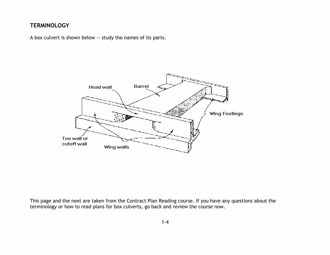
BOX CULVERTS DEFINITION A box culvert is a rectangular shaft, or tunnel, usually under a roadway. This shaft will typically have a clear span, or sum of spans, of 20 feet or less as measured along the roadway centerline. Box culverts are constructed when traditional drainage structures are too small to convey large volumes of water. Large box culverts are sometimes used to allow persons, animals or equipment to pass safely under the roadway. Box culverts are constructed of reinforced Portland cement concrete. The various parts of box culverts -- barrel, headwalls, toe walls, wingwalls, and wing footings -- are cast in place to form one structure, or are cast off site in a precast yard and then delivered to the site for assembly.
1-4
TERMINOLOGY
A box culvert is shown below -- study the names of its parts.
This page and the next are taken from the Contract Plan Reading course. If you have any questions about the terminology or how to read plans for box culverts, go back and review the course now.

1-5
The barrel has these parts
Culvert barrel dimensions are measured like this
Dimensions of box culverts are often written as Span x Height (for example, 8’ x 4’).

1-6
QUIZ
Box culverts are constructed of . Are box culverts usually constructed monolithically -- as one piece -- or are the various parts cast separately, but still joined? A box culvert is a structure under the roadway which has a clear span of than feet, as measured along the . If a box culvert is on a skew, will the roadway centerline be perpendicular to the box culvert centerline?

1-7
QUIZ, continued
Name the parts of the box culvert shown below:
Use this quiz as a quick review of the parts of box culverts. When you know all the parts, continue to the next page.

1-8
BRIDGES
TERMINOLOGY Let's begin by reviewing the basic parts of bridges. These are described below and shown on the next page.
The SUBSTRUCTURE includes the abutments, bents and piers -- the parts that support the girders (or beams) and deck.
The SUPERSTRUCTURE includes those parts of the bridge supported by the substructure - everything from the girders (or beams) up, including the bearing devices. The girders (or beams) are the major spanning members of the bridge.

1-9
Study this diagram. Then check yourself by taking the quiz on the next page.

1-10
QUIZ
The supporting structures of the bridge are called? . The substructure includes everything below the . The end substructures are either , which have a vertical wall the full height of the bridge, or . Vertical support members of bents are . Columns provide support in piers: they rest directly on a . On top of caps, the , support the beams. The flattened portion of an earth fill is a . The "roadway" of the bridge is the . What is the distance from one substructure to the next substructure called? The , prevents vehicles from veering off the bridge. The piles, footings, columns, walls and caps form the bridge . Any bridge part not in the substructure is in the . Linking the deck and the roadway are slabs. If you had some difficulties with this quiz, go back and review pages 1-8 and 1-9 before continuing on to the next section, TYPES OF BRIDGES.

1-11
TYPES OF BRIDGES
The Department uses a wide variety of bridge types. It is important to be familiar with them all. There are four major categories of bridges constructed by the Department as identified by their superstructure: beams or girders, slabs, draw or movable, and suspension. Other types, such as trusses and arches, exist in Florida but are no longer used for new construction. Following is a description of each category, in most common to least common order. BEAM OR GIRDER BRIDGES The term “beam” most often refers to members in the shorter span range – roughly up to 60 or 70 feet - or for steel members that are manufactured in one solid piece, called a "Rolled Section". The term “girder” most often refers to longer members - greater than 70 feet - or for a steel member that is manufactured by connecting separate flange and web plates by welding or bolting to make a "plate girder". Unlike rolled sections, plate girders are too large to be manufactured in one piece. All beam (or girder) bridges are constructed by using beams to span between bents, abutments or piers and then building a concrete or steel deck on top of the beams to provide a riding surface. Concrete Precast Prestressed Beam Bridges: This is the most common type of bridge in Florida. For this bridge, concrete beams are produced in a manufacturing plant called a "precast or prestress yard or plant" that is usually located some distance from the construction site. The beams are stored at the prestress yard until they are ready to be transported (by barge or truck) to the construction site. The Department has personnel at the prestress yard to make sure that the beams have been manufactured according to the specifications. Beams must have an approval stamp before they can be used in the project. This stamp is affixed by the Producer. Prestressed beams are built by stretching or stressing steel strands, and while keeping them stretched, encasing them in the beam concrete. Once the concrete is hard enough, the strands are released. This squeezes or compresses the beam concrete resulting in a very efficient use of both concrete - which has high compressive strength - and steel strand which has high tensile strength. The beams are manufactured or cast preliminary to being delivered to the construction site; hence the term "precast" and the steel strands are stressed preliminary to the placement of concrete, hence the term "prestressed."

1-12
There are many types of precast prestressed beams used by the Department: AASHTO, Florida I-Beam, Florida Bulb-T, Florida U-Beam, Inverted-Tee and Florida Double-Tee, with Florida I-beams being the most common. These come in various sizes. The AASHTO, Florida I-beam and Bulb-T beams are shaped like the letter “I”, the U-Beam like the letter
"U" (but with a flat bottom), the Inverted Tee like an upside down letter T ( │ ) and the Double-Tee like two letter
"T's" connected together at the top (TT). For detailed drawings of these beams see the latest Florida Department of Transportation, Structures Design Office, Standard Drawings. Concrete Precast Post-tensioned Beam Bridges: These beams are manufactured similarly to prestressed beams. They contain sufficient prestressing strands to allow the beams to be transported and to support their own weight. At the construction site, the beams receive additional steel strands that are threaded through ducts that are encased in the beam concrete along the beams length. The strands can also travel continuously through more than one beam. They continue through as many as three beams before they are stressed and permanently anchored at the ends of the beams. These additional strands give the beams the strength to support the deck and all other permanent loads (dead loads) and the loads of vehicles and pedestrians (live loads). This process results in a, "continuous beam", because the separate beams are connected together not only with the strands but also by pouring concrete connecting joints between each beam. Strand placement and stressing is postponed until after beam erection, hence the term "post-tensioned." Concrete Precast or Cast-In-Place (CIP) Post-tensioned Segmental Box Girder Bridges or Segmental Bridges: Segmental bridges are constructed using post-tensioned strands only, without any pretensioned strands. The box shaped girder segments are integral with the deck and are usually not longer than 20 feet. They are assembled on a temporary structure and are then post-tensioned together, or they are post-tensioned together one segment at a time to make a full span. Segmental bridges are used for longer spans, usually 140 feet long or greater. Segmental bridges are constructed with precast segments that are produced in a casting yard and transported to the job site, or are constructed with segments that are cast-in-place in their final position by using temporary supports to hold up the segments until the concrete is hard and can be post-tensioned. Segmental box girders can also be constructed in curved shapes. More detailed information on segmental bridges is available in the American Segmental Bridge Institute (ASBI) publication entitled Construction Practices Handbook for Concrete Segmental and Cable Supported Bridges.

1-13
Concrete Cast-In-Place Post-tensioned Box Girders: For these bridges, a box shaped girder is formed and is held in place by temporary supports or false work until the concrete is poured and is hard. Then post-tensioned strands are installed and stressed which gives the strength needed for the bridge to be self supporting and to allow the false work to be removed. Cast-in-place girders are usually continuous up to three or four spans and can be constructed in curved shapes. Steel Rolled Beam or Plate/Box Girder Bridges: Steel bridges are constructed by using rolled " I " shaped beams with wide flanges which are generally for shorter spans or by using plate/box girders which are used for long and/or curved spans. Rolled beams are usually delivered from the supplier in one piece that is the full span length. Plate/box girders are usually too long to transport in one piece and; therefore, are fabricated in pieces that are spliced together with bolts and splice plates at the job site. Plate/box girder spans routinely reach lengths of 250 to 300 feet. Plate girders have an "I" shape with wide flanges and box girders have a shape like a squared off letter "U" or a trapezoidal letter "U." Steel beam/girder bridges use a concrete deck. SLAB BRIDGES Concrete Cast-In-Place (CIP) Flat Slab Bridges: These bridges use thick concrete slabs to span between supports. Slabs can be as thick as 24 inches. They are formed on false work and reinforcement is provided by rebars only, without post-tensioning, and may be continuous for up to five or six spans. Span lengths rarely exceed 35 to 40 feet. Concrete Precast Prestressed Slab Bridges: Precast prestressed slabs are manufactured in widths that can be transported by truck. It is customary to pull the individual slabs together on site with transverse post-tensioning strands to make up the full bridge width. Sometimes an asphalt or concrete surface or topping is added. Span length and thickness ranges are approximately the same as for CIP slabs.

1-14
DRAWBRIDGES OR MOVABLE BRIDGES Bascule Bridges: This is the most common type of drawbridge and has steel plate girder main beams with secondary rolled beams to support the steel grid, or steel grid with concrete filled, decking. One end of the span is mounted on a horizontal steel shaft called a trunnion that allows the span to be rotated up and down to allow tall boats and barges to pass underneath the bridge. These bridges have complex mechanical and electrical systems which control the movement of the span. Bascule bridges can have one or two spans. Single span bridges are known as single leaf bascules and two spans are called double leaf. Vertical Lift Bridges: This type of movable bridge is no longer used for new construction by the Department. It is essentially a steel girder bridge with an entire center span that can be raised or lowered vertically by steel cables at the end of each span. Swing Bridges: Swing bridges are no longer used for new construction by the Department. These are steel girder bridges supported at the middle of the span by a horizontally rotating (pivot) pier. The span rotates ninety degrees to allow tall boats to pass by. SUSPENSION BRIDGES Cable Stayed Bridges: The Department currently has two cable stayed bridges. Both have center span lengths over 1200 feet. Cable stayed bridges have steel or concrete superstructures that are held up by large steel cables or bars attached to high towers. One end of Individual cables is attached to the tower and the other end is attached to the superstructure, which creates a spider web like pattern. Suspension bridges are used when long center spans are required to allow large ships to pass beneath the bridge without getting dangerously close to the piers. Main cable suspension bridges: The Department has only one of these suspension bridges. It has a classic style main cable that is draped between towers with vertical hanger cables that attach the main cable to the bridge superstructure. The Department's main cable suspension bridge has a center span of over 400 feet, but these type bridges, in other parts of the world, have been built with spans of over one mile.

1-15
QUIZ
Precast Prestressed Beams are manufactured where? Before a beam can be used in the project it must have an applied at the plant. Beams are called "Prestressed", because steel strands are stressed when? Strands are added at the job site to give the beam the capacity to carry the , , and loads. Beams are called "Post-tensioned", because steel strands are stressed when? True or false: Segmental bridge segments are assembled in the prestressed plant. , are used to reinforce CIP Flat slab bridges. Bascule bridge spans rotate on a large steel shaft called a . True or false: Florida suspension bridges are used because they are the least expensive type bridge to span across very deep water. If you had trouble with the quiz, review the sections of the text that caused the difficulty. If you had no trouble with the quiz, go directly to Chapter Two.

1-16
ANSWERS TO QUESTIONS Page 1-6 ● reinforced Portland cement concrete ● cast separately ● less, 20 feet, roadway centerline ● no Page 1-7 (1) barrel, (2) headwall, (3) toe wall or cutoff wall (4) wingwalls, (5) wing footings Page 1-10 ● substructures ● beams or girders ● abutments, end bents ● piles ● vertical, footing ● beam seats ● berm ● deck ● span ● barrier wall ● substructure ● superstructure ● approach
Page 1-15 ● precast or prestressed yard or plant ● approval stamp ● before the concrete is placed ● deck, other permanent loads, live ● after the concrete has hardened ● false, they are assembled at the job site ● rebars ● trunnion ● false, they are used to provide a safe distance
between piers and large ship