Embed Size (px)
DESCRIPTION
Struktur+1.3+25Febr2013
Citation preview

Rangka BatangTruss - Fachwerk
Metode SambunganMethod of Joints
2MEC/D-2014

Contents
6 - 2
• Pendahuluan• Definisi Struktur – Rangka Batang• Struktur /Rangka Batang Sederhana• Analisis Struktur/Rangka Batang dengan Metoda Sambungan• Struktur/Rangka Batang yang terdiri dari beberapa Struktur/Rangka
Batang sederhana• Contoh Soal 1• Contoh Soal 2• Contoh Soal 3• Contoh Soal 4• Contoh Soal 5

Pendahuluan
6 - 3
• Kesetimbangan struktur yang terbuat dari bagian atau batang-batang yang disambung, terjadi gaya-yaya luar (reaksi tumpuan, beban) dan gaya dalam batang (tarik, tekan, geser) yang perlu diperhatikan.
• Interaksi antara batang-batang atau bagian-bagian yang tersambung, berlaku hukum Newton’s ke-3, yang menyatakan bahwa gaya aksi dan reaksi pada batang/bagian yang tersambung mempunyai besar, dan garis kerja yang sama, tetapi berlawanan arah
• Terdapat 3 kategori dalam struktur enjiniring, sbb:a) Rangka: terdiri dari minimal satu bagian dengan
beban multipel. Contoh: batang AD dan batang CFb) Rangka Batang: dibentuk oleh bagian-bagian atau
batang-batang yang hanya mendapatkan 2 beban. Contoh: batang BE
c) Mesin: struktur yang ada bagian bergeraknya untuk memindahkan atau mengubah gaya.

Definisi Rangka Batang
6 - 4
• Rangka Batang terdiri dari batang-batang lurus yang tersambung, dan tidak ada batang yang tanpa sambungan. Contoh: Rangka Batang disamping terdiri dari batang AC, AD, BC, BD, CD, bukan batang AB
• Sambungan baut, keling, atau las diasumsikan sebagai sambungan pin yang sempurna. Gaya-gaya yang bekerja diujung batang disederhanakan menjadi gaya tunggal dan tidak ada kopel, sehingga batang dianggap mendapatkan 2 beban saja.
• Struktur pada umumnya dibentuk dari beberapa Rangka Batang yang digabungkan sehingga membentuk Rangka Batang Ruang. Masing-masing Rangka Batang menerima beban pada bidangnya masing-masing, sehingga bisa diberlakukan Rangka Batang pada bidang.
• Bila 2 gaya cenderung menarik batang, maka batang menerima beban tarik. Sebaliknya bila cenderung menekan maka batang menerima beban tekan

Definisi Rangka Batang
6 - 5
• Batang-batang pada struktur Rangka Batang pada umumnya tidak terlalu besar sehingga tidak mampu menerima beban melintang yang besar.
• Beban beban dikenakan pada sambungan

Jenis Rangka Batang

Rangka Batang Sederhana
6 - 7
• Rangka Batang yang kekar dan kuat tidak akan kolaps atau berubah bentuk bila dibebani.
• Rangka Batang Sederhana dibuat dengan menambahkan 2 batang dan satu sambungan pada segitiga dasar Rangka Batang.
• Pada Rangka Batang sederhana kestabilannya dapat ditentukan berdasarkan rumusan, m = 2n - 3 dimana m adalah jumlah batang dan n adalah jumlah sambungan

Analisis Rangka Batang dengan Metoda Sambungan
6 - 8
• Dismember the truss and create a freebody diagram for each member and pin.
• The two forces exerted on each member are equal, have the same line of action, and opposite sense.
• Forces exerted by a member on the pins or joints at its ends are directed along the member and equal and opposite.
• Conditions of equilibrium on the pins provide 2n equations for 2n unknowns. For a simple truss, 2n = m + 3. May solve for m member forces and 3 reaction forces at the supports.
• Conditions for equilibrium for the entire truss provide 3 additional equations which are not independent of the pin equations.

Contoh (1)
• Rangka Batang dengan 9 (sembilan) batang dan 6 (enam) sambungan
• A – tumpuan tetap• D – tumpuan bebas
• Beban L diketahui besarnya dan dengan arah seperti pada gambar

Reaksi Tumpuan
• Besar reaksi gaya pada tumpuan dihitung terlebih dahulu, supaya bisa memulai
• Prinsip kesetimbangan: ∑F = 0 dan ∑M = 0
• R1 dan R2 bisa ditentukan terlebih dahulu

Metode Sambungan
• Semua sambungan diasumsikan “sambungan pin”
• Gaya luar/eksternal ditransformasikan menjadi gaya internal melalui batang
• Batang: Kesetimbangan 2 gaya (collinear)
• Gaya Tarik (Tension) atau Gaya Tekan (Compression)

Sambungan A
• DBB sambungan A, bekerja gaya-gaya R1, FAB, dan FAF
• Batang AF menerima beban/gaya Tekan (-), sedangkan batang AB menerima beban/gaya Tarik (+)
• Besar gaya dalam masing-masing batang bisa dihitung dengan memanfaatkan diagram gaya
DBB
Diagram Gaya

Sambungan F
• DBB sambungan F, bekerja gaya-gaya FAF, FBF, dan FEF
• Batang AF sudah dihitung melalui sambungan A, Batang EF menerima beban/gaya Tekan (-), sedangkan batang BF menerima beban/gaya Tarik (+)
• Besar gaya bisa dihitung dengan memanfaatkan diagram gaya
DBB
Diagram Gaya

Sambungan B
• DBB sambungan B, bekerja gaya-gaya FBC, FBE, FBE, FAB, dan L
• Batang BF sudah dihitung melalui sambungan F, Batang AB, BC, dan BE menerima beban/gaya Tarik (+)
• Besar masing-masing gaya dalam batang bisa dihitung dengan memanfaatkan diagram gaya
DBB
Diagram Gaya

Sambungan C
• DBB sambungan C, bekerja gaya-gaya FBC, FCD, dan FCE
• Apabila CE ≠ 0, maka tidak terjadi kesetimbangan di sambungan C
• Batang BC sudah dihitung melalui sambungan B, dan batang CD tentunya harus membuat sambungan C setimbang, FBC = FCD
DBB
Sambungan E
• DBB sambungan E, bekerja gaya-gaya FBE, FDE, dan FEF
• Batang EF dan DE menerima beban Tekan (-), sedangkan batang BE sudah dihitung melalui sambungan B sebelumnya.
• Besar gaya dalam batang lainnya bisa dihitung dengan memanfaatkan diagram gaya
DBB
Diagram Gaya

Sambungan D
• DBB sambungan D, bekerja gaya-gaya FCD, FDE, dan R2
• Batang DE sudah ditentukan sebelumnya melalui sambungan E. Batang CD menerima beban Tarik (+)
• Besar gaya dalam batang CD bisa dihitung dengan memanfaatkan diagram gaya
DBB
Diagram Gaya

Diagram Rangka BatangTruss Diagram
• Rangka Batang ditampilkan menyeluruh
• Setiap batang dilengkapi dengan panah pada ujungnya
• Arah panah menuju sambungan, berarti batangnya menerima beban Tekan (-)
• Arah panah menjauhi sambungan, berarti batangnya menerima beban Tarik (+)

Joints Under Special Loading Conditions 6 -
19
• Forces in opposite members intersecting in two straight lines at a joint are equal.
• The forces in two opposite members are equal when a load is aligned with a third member. The third member force is equal to the load (including zero load).
• The forces in two members connected at a joint are equal if the members are aligned and zero otherwise.
• Recognition of joints under special loading conditions simplifies a truss analysis.

Sample Problem 6.1
6 - 20
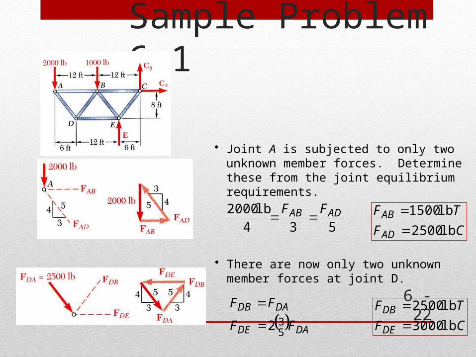
Using the method of joints, determine the force in each member of the truss.
SOLUTION:• Based on a free-body diagram of the
entire truss, solve the 3 equilibrium equations for the reactions at E and C.
• Joint A is subjected to only two unknown member forces. Determine these from the joint equilibrium requirements.
• In succession, determine unknown member forces at joints D, B, and E from joint equilibrium requirements.
• All member forces and support reactions are known at joint C. However, the joint equilibrium requirements may be applied to check the results.

Sample Problem 6.1 6 -
21
SOLUTION:• Based on a free-body diagram of the entire truss,
solve the 3 equilibrium equations for the reactions at E and C.
ft 6ft 12lb 1000ft 24lb 2000
0
E
MC
lb 000,10E
xx CF 0 0xC
yy CF lb 10,000 lb 1000 - lb 20000
lb 7000yC
Sample Problem 6.1
6 - 22
• Joint A is subjected to only two unknown member forces. Determine these from the joint equilibrium requirements.
534
lb 2000 ADAB FF
CF
TF
AD
AB
lb 2500
lb 1500
• There are now only two unknown member forces at joint D.
DADE
DADB
FF
FF
532
CF
TF
DE
DB
lb 3000
lb 2500

Sample Problem 6.1
6 - 23
• There are now only two unknown member forces at joint B. Assume both are in tension.
lb 3750
25001000054
54
BE
BEy
F
FF
CFBE lb 3750
lb 5250
375025001500053
53
BC
BCx
F
FF
TFBC lb 5250
• There is one unknown member force at joint E. Assume the member is in tension.
lb 8750
37503000053
53
EC
ECx
F
FF
CFEC lb 8750

Sample Problem 6.1 6 -
24
• All member forces and support reactions are known at joint C. However, the joint equilibrium requirements may be applied to check the results.
checks 087507000
checks 087505250
54
53
y
x
F
F
Analysis of Trusses by the Method of Sections 6 -
25
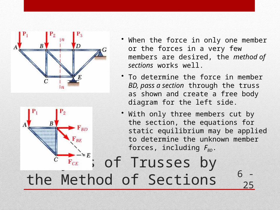
• When the force in only one member or the forces in a very few members are desired, the method of sections works well.
• To determine the force in member BD, pass a section through the truss as shown and create a free body diagram for the left side.
• With only three members cut by the section, the equations for static equilibrium may be applied to determine the unknown member forces, including FBD.

Trusses Made of Several Simple Trusses 6 -
26
• Compound trusses are statically determinant, rigid, and completely constrained.
32 nm
• Truss contains a redundant member and is statically indeterminate.
32 nm
• Necessary but insufficient condition for a compound truss to be statically determinant, rigid, and completely constrained,
nrm 2
non-rigid rigid
32 nm
• Additional reaction forces may be necessary for a rigid truss.
42 nm

Sample Problem 6.3 6 -
27
Determine the force in members FH, GH, and GI.
SOLUTION:• Take the entire truss as a free body.
Apply the conditions for static equilib-rium to solve for the reactions at A and L.
• Pass a section through members FH, GH, and GI and take the right-hand section as a free body.
• Apply the conditions for static equilibrium to determine the desired member forces.

Sample Problem 6.3 6 -
28
SOLUTION:• Take the entire truss as a free body.
Apply the conditions for static equilib-rium to solve for the reactions at A and L.
kN 5.12
kN 200
kN 5.7
m 25kN 1m 25kN 1m 20
kN 6m 15kN 6m 10kN 6m 50
A
ALF
L
L
M
y
A

Sample Problem 6.3 6 -
29
• Pass a section through members FH, GH, and GI and take the right-hand section as a free body.
kN 13.13
0m 33.5m 5kN 1m 10kN 7.50
0
GI
GI
H
F
F
M
• Apply the conditions for static equilibrium to determine the desired member forces.
TFGI kN 13.13

Sample Problem 6.3 6 -
30
kN 82.13
0m 8cos
m 5kN 1m 10kN 1m 15kN 7.5
0
07.285333.0m 15
m 8tan
FH
FH
G
F
F
MGL
FG
CFFH kN 82.13
kN 371.1
0m 10cosm 5kN 1m 10kN 1
0
15.439375.0m 8
m 5tan
32
GH
GH
L
F
F
M
HI
GI
CFGH kN 371.1

Analysis of Frames 6 - 31
• Frames and machines are structures with at least one multiforce member. Frames are designed to support loads and are usually stationary. Machines contain moving parts and are designed to transmit and modify forces.
• A free body diagram of the complete frame is used to determine the external forces acting on the frame.
• Internal forces are determined by dismembering the frame and creating free-body diagrams for each component.
• Forces between connected components are equal, have the same line of action, and opposite sense.
• Forces on two force members have known lines of action but unknown magnitude and sense.
• Forces on multiforce members have unknown magnitude and line of action. They must be represented with two unknown components.

Frames Which Cease To Be Rigid When Detached From Their Supports
6 - 32
• Some frames may collapse if removed from their supports. Such frames can not be treated as rigid bodies.
• A free-body diagram of the complete frame indicates four unknown force components which can not be determined from the three equilibrium conditions.
• The frame must be considered as two distinct, but related, rigid bodies.
• With equal and opposite reactions at the contact point between members, the two free-body diagrams indicate 6 unknown force components.
• Equilibrium requirements for the two rigid bodies yield 6 independent equations.
Sample Problem 6.4 6 -
33
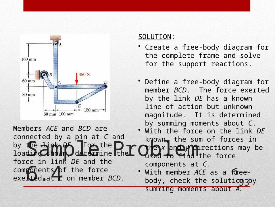
Members ACE and BCD are connected by a pin at C and by the link DE. For the loading shown, determine the force in link DE and the components of the force exerted at C on member BCD.
SOLUTION:• Create a free-body diagram for the
complete frame and solve for the support reactions.
• Define a free-body diagram for member BCD. The force exerted by the link DE has a known line of action but unknown magnitude. It is determined by summing moments about C.
• With the force on the link DE known, the sum of forces in the x and y directions may be used to find the force components at C.
• With member ACE as a free-body, check the solution by summing moments about A.

Sample Problem 6.4 6 -
34
SOLUTION:• Create a free-body diagram for the complete frame
and solve for the support reactions.
N 4800 yy AF N 480yA
mm 160mm 100N 4800 BM A N 300B
xx ABF 0 N 300xA
07.28tan150801
Note:

Sample Problem 6.4 6 -
35
• Define a free-body diagram for member BCD. The force exerted by the link DE has a known line of action but unknown magnitude. It is determined by summing moments about C.
N 561
mm 100N 480mm 06N 300mm 250sin0
DE
DEC
F
FM CFDE N 561
• Sum of forces in the x and y directions may be used to find the force components at C.
N 300cosN 561 0
N 300cos0
x
DExx
C
FCF
N 795xC
N 480sinN 5610
N 480sin0
y
DEyy
C
FCF
N 216yC

Sample Problem 6.4 6 -
36
• With member ACE as a free-body, check the solution by summing moments about A.
0mm 220795mm 100sin561mm 300cos561
mm 220mm 100sinmm 300cos
xDEDEA CFFM
(checks)

Machines 6 - 37
• Machines are structures designed to transmit and modify forces. Their main purpose is to transform input forces into output forces.
• Given the magnitude of P, determine the magnitude of Q.
• Create a free-body diagram of the complete machine, including the reaction that the wire exerts.
• The machine is a nonrigid structure. Use one of the components as a free-body.
• Taking moments about A,
Pb
aQbQaPM A 0