Embed Size (px)
Citation preview

STOP!STOP!
Call Us First!DO NOT RETURN TO STORE.
For immediate help with assembly or product information
call our toll-free number:
or email:
Our staff is ready to provide assistance.
April through October M - F 8:00 AM to 7:00 PM EST
Saturday 8:30 AM to 4:30 PM EST
November through March M - F 8:00 AM to 5:00 PM EST
1-800-844-9273
16639

(This page intentionally left blank.)

BEFORE YOU BEGIN
IMPORTANT!READ INSTRUCTIONS THOROUGHLY PRIOR TO BEGINNING ASSEMBLY.
- CUSTOMER SERVICE -
Call: 1-800-844-9273 email: [email protected]
• BUILDING RESTRICTIONS AND APPROVALS Be sure to check local building department and homeowners association for specific restrictions and/ or requirements before building• ENGINEERED DRAWINGS Contact our Customer Service Team if engineered drawings are needed to pull local permits.• SURFACE PREPARATION To ensure proper assembly you must build your shed on a level surface. Recommended methods and materials to level your shed are listed on page 8• CHECK ALL PARTS Inventory all parts listed on pages 4-6. Contact our Customer Service Team if any parts are missing or damaged.• ADDITIONAL MATERIALS You will need additional materials to complete your shed. See page 3 for required and optional materials and quantities.
10/10/2011
KEEP THIS MANUAL FOR FUTURE REFERENCE
ASSEMBLY MANUAL
ACTUAL FLOOR SIZE IS 116-1/2 x 96" (295,9 x 243,8 cm)BRIDGEPORT 10' x 8' (305 x 244 cm)
16639
A Backyard Products Company
2
FINISH
BEGIN
1̧
TOOLS
Safety!Alwaysuseapprovedsafetyglassesduringassembly.
OptionalRequired
HELPFUL REMINDER SYMBOLSLookforthesesymbolsforhelpfulremindersthroughoutthismanual.
ORIENT LUMBER AND TRIM FOR BEST APPEARANCE
=AssistanceRequired;twoormorepeople.
=Ensuresquareness.
=Importantrequiredsteporoperation.
=Helpfulassemblyhint.
=Markpartwithpencil.
=Beginningofstepsforassemblyorinstallation.
=Youhavefinishedtheassemblyorinstallation.
=Level
�Gloves
�Clamps
�Saw
Framinglumberisgradedforstructuralstrengthandnotappearance.Exteriortrimisgradedforonegoodside.
Alwaysinstallthematerialleavingthebestedgeandbestsurfacevisible.Pleaserememberthattheseblemishesinnowaynegativelyaffectthestrengthorintegrityofourproduct.(SeeFig. A,B,C.)
�SafetyGlasses
�TapeMeasure
�PaintTools
�Ladder
�ExteriorratedWoodGlue
�CaulkGun� Hammer
�Level
�Pencil
�Phillips Screwdriver
�Drill/Driver�3/8"DrillBit�#2PhilipsDriveBit
�ToolBelt/NailPouch
�ChalkLine
�NailGun
•GunNails
�Square or
�ShingleBlades
A B C
�UtilityKnife

3
12"(30,5 cm)
COMPLETING YOUR SHED Youwillneedtheseadditionalmaterials:
OPTIONAL MATERIALS
FOUNDATION OR FLOOR MATERIALS
ADDITIONAL MATERIALS
DRIP EDGE ..................... 40 Feet #15 ROOFING FELT Tocover100Sq.Ft.ofroofarea.
1" GALVANIZED ROOFING NAILS.........1/4 LbForroofingfelt.
REFER TO THE BACK OF THIS MANUAL AND THE MANUFACTURER’S INSTRUCTIONS FOR INSTALLATION OF SHINGLES, DRIP EDGE AND FELT.
•Thisshedkitincludesacompletewoodfloorsystem.•ItdoesnotincludeANYlevelingmaterials.•See the FLOOR LEVELING section on page 8 for recommended methods and suggested materials to properly level your floor, as this will vary depending on your specific site.
3-TAB SHINGLES ...........................................5 Bundles
PAINT FOR SIDING ........................................2 GallonsUse100%acryliclatexexteriorpaint.(2)coatsrecommended.
CAULK ............................................................2 TubesUseacryliclatexexteriorcaulkthatispaintable.
1" GALVANIZED ROOFING NAILS.... 2 Lbs Forshingles.
PAINT FOR TRIM .............................1 QuartUse100%acryliclatexexteriorpaint. WOOD GLUE ....................... Exterior Rated
IMPORTANT!Theincludedfloorhasbeendesignedforgeneraluse.Dependingonyourspecificuseyoumaywanttoconstructaheavydutyfloorframebyaddingadditionalfloorjoists(shownbelowasshaded).Belowisalistofadditionalmaterials(notincluded).
x5
x20
2x4x8'(5,1x10,2x243,8cm)TreatedLumber
Cutlumberto2x4x93"(5,1x10,2x236,2cm)TreatedLumber
ea.3"(7,6cm)galvanizednails
Optional12"(30,5cm)spacing
Standard24"(61cm)spacing
REINFORCED WOOD FLOOR FRAME (OPTIONAL)

4
RS RS1" x 4".................3/4" x 3-1/2" (1,9 x 8,9 cm)
2" x 4"..............1-1/2" x 3-1/2" (3,8 x 8,9 cm)
2" x 3"..............1-1/2" x 2-1/2" (3,8 x 6,3 cm)
1" x 3".................3/4" x 2-1/2" (1,9 x 6,3 cm)
WOOD SIZE CONVERSION CHARTNominal Board Size Actual Size
PARTS IDENTIFICATION AND SIZESF
LO
OR
DO
OR
SR
OO
FT
RIM
WA
LL
S
Part identification is stamped on some parts.
• Check these locations for Part stamps
Treated lumber is stamped:
Treated lumber is stamped:
PARTS LISTINVENTORY YOUR PARTS before you begin. We suggest sorting parts by the category they are listed in.
AH
TREATEDx2 2 x 4 x 92-1/2" (5,1 x 10,2 x 235 cm)
TREATEDx6 2 x 4 x 93" (5,1 x 10,2 x 236,2 cm)
TREATEDx2 2 x 4 x 24" (5,1 x 10,2 x 61 cm)
x2
OTx12 2 x 3 x 68" (5,1 x 7,6 x 172,7 cm)
PTx3 2 x 3 x 96" (5,1 x 7,6 x 243,8 cm)
VXx2 2 x 6 x 96" (5,1 x 15,2 x 243,8 cm)
DJx2 2 x 3 x 10-1/4" (5,1 x 7,6 x 26 cm)
NNx2 2 x 3 x 47-3/4" (5,1 x 7,6 x 121,3 cm)
OZx2 2 x 3 x 70-1/4" (5,1 x 7,6 x 178,4 cm)
NHx2 2 x 3 x 46-1/4" (5,1 x 7,6 x 117,5 cm)
PSx6 2 x 3 x 91" (5,1 x 7,6 x 231,1 cm)
CRx2 2 x 6 x 21-1/4" (5,1 x 15,2 x 54 cm)
RKx4 2 x 3 x 13" (5,1 x 7,6 x 33 cm)
DEx4 2 x 3 x 15-7/8" (5,1 x 7,6 x 40,3 cm)
DGx2 2 x 3 x 26-1/4" (5,1 x 7,6 x 66,7 cm)
LRx6 2 x 3 x 19" (5,1 x 7,6 x 48,3 cm)
DDx8 2 x 4 x 57-3/4" (5,1 x 10,2 x 146,7 cm)
JFx2 1 x 4 x 60" (2,5 x 10,2 x 152,4 cm)
x8
x2
3/8 x 1-3/4 x 72" (1 x 4,5 x 182,9 cm)
1 x 3 x 96" (2,5 x 7,6 x 243,8 cm)
x2 1 x 3 x 22-5/8" (2,5 x 7,6 x 57,5 cm)
CNx4 2 x 4 x 59-1/4" (5,1 x 10,2 x 150,5 cm)
CT
CP
x2 1 x 3 x 22" (2,5 x 7,6 x 55,4 cm)
19/32 x 2-1/2 x 26-5/8" (1,5 x 6,4 x 67,6 cm)
OOx2
x1
2 x 3 x 69" (5,1 x 7,6 x 175,3 cm)
3/8 x 1-3/4 x 69" (1 x 4,4 x 175,3 cm)
x8 6 x 24" (15,2 x 61 cm)
BE
1 x 3 x 5" (2,5 x 7,6 x 12,7 cm)Gauge Block for 3/4" (1,9 cm)measurement
x1
3/4"(1,9 cm)
LFx2 2 x 3 x 21-1/2” (5,1 x 7,6 x 54,6 cm)
GAA

5
WALL PANEL & DOOR PARTS LIST
NOTE: Panel parts are not stamped with part identification.
Floor panels are 5/8" (15,8 mm) thick.
Loft & shelf panels are 7/16" (11 mm) thick.
5/8x20-1/2x96"(1,6x60,6x243,8cm)
x1
x2
5/8x48x96"(1,6x121,9x243,8cm)
x2
x2
x2 x2 x2x2
x1RIGHT DOOR
x1LEFT DOOR
x13/8x23-7/8x72"(1x60,6x182,9cm)
x23/8x15-7/8x72"(1x40,3x182,9cm)
x23/8x46-1/8x72"(1x117,2x182,9cm)
x43/8x48x72"(1x121,9x182,9cm)
x2 3/8x10-1/4x72"(1x26x182,9cm)
Roof panels are 7/16" (11 mm) thick.
7/16x48x96"(1,1x121,9x243,8cm)
7/16x23-7/8x48"(1,1x60,6x121,9cm)
7/16x11-1/4x96"(1,1x28,6x243,8cm)
7/16x11-1/4x23-7/8"(1,1x28,6x60,6cm)
x2
x2
x2
x2
ROOF PANELS
FLOOR PANELS
LOFT & SHELF PANELS
7/16x23-7/8x91"(1,1x91,4x244cm)
7/16x11-7/8x91"(1,1x60,6x231cm)

6
DOOR HARDWARE & VENT
NAIL BOXES
FASTENER/HARDWARE BAG
2"(5,1cm)
3"(7,6cm)
3"(7,6cm)
x3 BOXES
x4 BOXES
2"(5,1cm)
2"(5,1cm)
1-1/4"(3,2cm)
3/4"(1,9cm)
x14
x85
x98
x55
x73
1-1/2"(3,8cm)x150
NOTES
x2
x8
x16x12
3/4"(1,9cm)
3/4"(1,9cm)1/2"(1,3cm)
x2
x1
1-1/2"(3,8cm)
10-1/2x28-1/4"(26,7x71,4cm)
x2
3/4"(1,9cm)x12
x4
8x16"(20,3x35,6cm)
x2

7
BUILDING ANATOMY
1
3
2
5
4
1. Sub-assembled doors with attached hinges.
2. 2x3 wall studs have been engineered to support roof load and to meet demanding wind loads.
3. Sidewall top and bottom plates tie wall studs together and provide nailing support for top and bottom edge of siding.
5. Siding overhangs the wall framing and floor to keep the elements out.
6. Collar tie maintains door frame integrity. 7. Includes treated floor frame and sturdy Oriented Strand Board (OSB) floor deck.
All of our buildings have been engineered to withstand demanding wind and snow loads. If you live in an area with extreme wind/snow load requirement, contact
us and we can assist with engineering to meet your local codes.
1
2
3
4
5
6
6

8
FLOOR LEVELING OPTIONS Therearemultiplewaystolevelyourfloorframe.Ourrecommendedlevelingmethodisshownbelow.
Levelingmaterialsarenotincludedinthiskit.
PREFERRED METHOD - 4x4 TREATED RUNNERS
Measurements to centers of 4x4's.
•3"(7,6cm)Screwsangledinto4x4.
•(2)ateachpointframe•and4x4touch.
12"(30,5cm)
12"(30,5cm)
•Levelunder4x4runnersonly.•Locatelevelingmaterial12"(30,5cm)fromendsofrunnersandnomorethan48"(121,9cm)apart.•Asphaltshinglesshouldbeusedbetween4x4runnersandblocksortreatedlumber.Neveruseshinglesindirectcontactwithground.•Forbestresultsandaidinginwaterdrainageusegravelundereachconcreteblock.
LEVELING METHODS
•Ifyouarebuildingyourshedonaconcretefoundationseethefollowingpage.
CONCRETE
MATERIAL REQUIRED
x2 4"x4"x10'(10,2x10,2x304,8cm)TreatedLumber
Fasteners for Frame to 4"x 4". (3"(7,6cm)Screwsshownasoneoption.)Minimum(24)3"(7,6cm)screws/exteriorgrade.
Use only wood treated for ground contact and fasteners approved for use with treated wood.
Always support frame seams.
Leveling higher than 16" (40,3 cm) not recommended.
LEVELING MATERIALSGravel
2x4TreatedLumber
SolidMasonryBlocksin1",2",4"or8"thickness
AsphaltShingles
8"Block
4"BlockGravelGravel
4x4Runner
Shingle
ShingleMaximumbetweenlevelingmateriallocations.
48"(121,9cm)
12"(30,5cm)
12"(30,5cm)
2x4TreatedLumber
2"Block
Level
Donotexceed16"(40,3cm).

9
A
BC
4"(10,2 cm)
3-1/2"(8,9 cm)
DOOR
2"x4"x8'(5,1x10,2x243,8cm)
Caulk
Requires:
x2
x2
x1
MUST be treated lumber.
MUST be treated lumber.
96" (243,8 cm)116-1/2" x 96" (295,9 x 243,8 cm) 89" (226,1 cm)10'x 8' (304,8 x 243,8 cm) 116-1/2" (295,9 cm)
AActual Size B CBuilding Size
CONCRETE FOUNDATION Yourkitcontainsallmaterialstoconstructawoodenfloor.Ifyouchoosetoinstallyourkit
onaconcreteslabrefertothediagrambelow.
•Atreated2x4"(5,1x10,2cm)sillplateisrequiredwheninstallingyourshedonconcrete.Hint: Use treated lumber in your kit or purchase full length treated lumber.•Useahighqualityexteriorgradecaulkbeneathallsillplates.•Fasten2x4"(5,1x10,2cm)sillplatestoslabusingapprovedconcreteanchors(fasteners not included).•Checklocalcodeforconcretefoundationrequirements.
NOTES
Treated Sill Plate
Caulk betweensill plate andconcrete.
Allownewconcreteslabstocureforatleastseven(7)days.
2"x4"x10'(5,1x10,2x304,8cm)

10
DOOR
First, secureat ends withone fastener.
Second, secureat ends withone fastener.
151"(385,5cm)
151"(385,5cm)
Fig. A
FINISH
5
LEVEL AND SQUARE FLOOR FRAMEBeforeattachingfloordecking,itisimportanttolevelandsquarethefloorframe.
Alevelandsquarefloorframeisrequiredtocorrectlyconstructyourshed.
BEGIN
1̧
2
3
4
Uselevelandchecktheframeislevelbeforeapplyingfloorpanels.
Checkforframesquarenessbymeasuringdiagonallyacrosscorners.Ifthemeasurementsarethesame,theframeissquare.Thediagonalmeasurementwillbeapproximately151"(385,5cm).
Whentheframeislevelandsquaresecureonesideofframetothe4x4runnersusingonefasteneratendsofeachrunner.Movetotheoppositeendoftheframe.Securetheframeto4x4runnerswithonefasteneratendsofeachrunnermakingsuretheframeremainssquare(Fig. A).
Oncethefloorframeislevelandsquarefastentheframetoateachpointtheframecontactsthe4x4runners.
Seepage8forthepreferredfloorlevelingmethod.
FLOOR FRAME

11
93"(236,2 cm)
Center on marks
Center onmarks
SEAM
SEAM
96"(243,8 cm)
116-1/2"(295,9 cm)
96"(243,8 cm)
92-1/2"(235 cm)
72"(182,9 cm)
48"(121,9 cm)
24"(61 cm)
24"(61 cm)
20-1/2"(52,1 cm)
1-1/2”(3,8 cm)
DOOR
x 283"(7,6cm)
PARTS REQUIRED:
FINISH
3 Youhavefinishedyourfloorframe.Proceedtolevelandsquareframe.
Usetwo3"(7,6cm)nailsateachmark,andfour3"(7,6cm)nailsatseamsasshown.
Orientpartsasshownonflatsurface.Measureandmarkeachdimensionfromendofboards.
FLOOR FRAME
Flush
Flush
NOTE:Lookfor
StampTREATED
2
BEGIN
1̧
HINT:For easier nailingstand on frame.
TREATED
TREATED
TREATEDx62x4x93"(5,1x10,2x236,2cm)
x22x4x92-1/2"(5,1x10,2x235cm)
x22x4x24"(5,1x10,2x61cm)
3"(7,6cm)Nails
3"(7,6cm)Nails
NOTE THISMEASUREMENT

12
DOOR
48"(121,9 cm)
20-1/2"(52,1 cm)
96"(243,8 cm)
6" (15,2 cm)edges of panel
12" (30,5 cm)inside panel
DOOR
PARTS REQUIRED:
x1
x52
5/8x48x96"(1,6x121,9x243,8cm)
Grid linesUP Flush
Flush
Flush
Flush
Flush atoppositecorneredge
Seams
(2)Nails
(2)Nails
FLOOR
3/4"(1,9cm)
Attachthe48x96"(121,9x243,8cm)panelwiththeroughsideup(painted-gridlinesside)withthe48"(121,9cm)edgeandcornerflushtothefloorframe(Fig A).Securepanelwithtwo2"(5,1cm)nailsinthecorners.
Movetotheoppositeside.Usingthelongedgeofthepanelasalever,movethepanelside-to-sideuntilcornerisflushtothefloorframe(Fig. B).Securepanelwithtwo2"(5,1cm)nailsinthecorners.
2
BEGIN
1̧1
3
4 Continueattachingthepanelusing2"(5,1cm)nails6"(15,2cm)apartonedges,and12"(30,5cm)apartinsidepanel.
Ensure your floor frame is square by installing one panel and squaring frame.
Fig. A
Fig. B
Fig. C
Checkthefloorframeissquarebymeasuringdiagonallyacrosstheframecorners.Ifthemeasurementsarethesameyourfloorframeissquare.Themeasurementwillbeapproximately151"(383,5cm)(Fig. C).
151"(383,5cm)
151"(383,5cm) 151"
(383,5cm)
2"(5,1cm)

13
48"(121,9 cm)
20-1/2"(52,1 cm)
96"(243,8 cm)
6"(15,2 cm)
12"(30,5 cm)
DOOR
PARTS REQUIRED:
FINISH
7 Youhavefinishedattachingyourfloorpanels.
Continueinstallingpanelswithroughsideup(paintedgridlines).
Useachalklineorgridlinesonpanelfor2"(5,1cm)nails6"(15,2cm)apartonedges,and12"(30,5cm)apartinsidepanels.
5
76
x1 x1
5/8x48x96"(1,6x121,9x243,8cm)
5/8x20-1/2x96"(1,6x52,1x243,8cm)
Grid linesUP
x962"(5,1cm)
FLOOR PANELS
Flush
Flush
Flush
Flush

14
Side wall
Side wall
Front wall
Back Wall
Check the floor frame is level after installing floor panels. Re-level if needed.
• The floor should be used as a level work surface for wall construction.
• Organize your wall sections during sub-assembly to avoid over-handling of the walls.HINT:
IMPORTANT!
15
48-3/4"(123,8cm)
2-1/2"(6,4cm)
2-1/2"(6,4cm) Flush
PARTS REQUIRED:
3
2
4
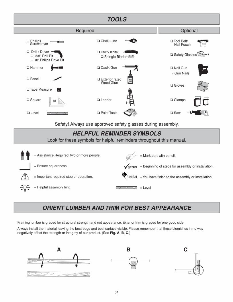
NailNNfirst,1"(2,5cm)frompanelbottom.
Use1-1/2"(3,8cm)nails6"(15,2cm)apart.
PlacePSflushtoNNand2-1/2"(6,4cm)overhangistooutside.Holdthe48-3/4"(123,8cm)measurementandsecurewith1-1/2"(3,8cm)nails12"(30,5cm)apart.
You will build 2 side walls the same.
OrientNNandPSonflatonfloorasshown.
Placepanelonthemwithprimedsideup.
Primed side up
BEGIN
1̧
LEFT WALL
x2
3/8x48x72"(0,9x121,9x182,9cm)
x2
x2
2x3x47-3/4"(5x7,6x121,3cm)
2x3x91"(5x7,6x231,1cm)
NN
PS
x28 1-1/2"(3,8cm)
6"(15,2cm)
2-1/2"(6,4cm)
Nails
2-1/2"(6,4cm)
48-3/4"(123,8cm)
72"(182,9cm)
12"(30,5cm)
1"(2,5cm)
1-1/4"(3,2cm)
NNPS
16
x22x3x91"(5x7,6x231,1cm)
SIDE WALL ASSEMBLIES
PS
PARTS REQUIRED: x26 1-1/2"(3,8cm)
7
5
6
LRx22x3x19"(5,1x7,6x48,3cm)
19-1/2"(49,5cm)
19"(48,3cm)
19-1/2"(49,5cm)
2-1/2"(6,4cm)
45-1/2"(115,6cm)
45-1/2"(115,6cm)
2-1/2"(6,4cm)
2-1/2"(6,4cm)
1-1/4"(3,2cm)
1/2"(1,3cm)
LR
PS6"
(15,2cm)
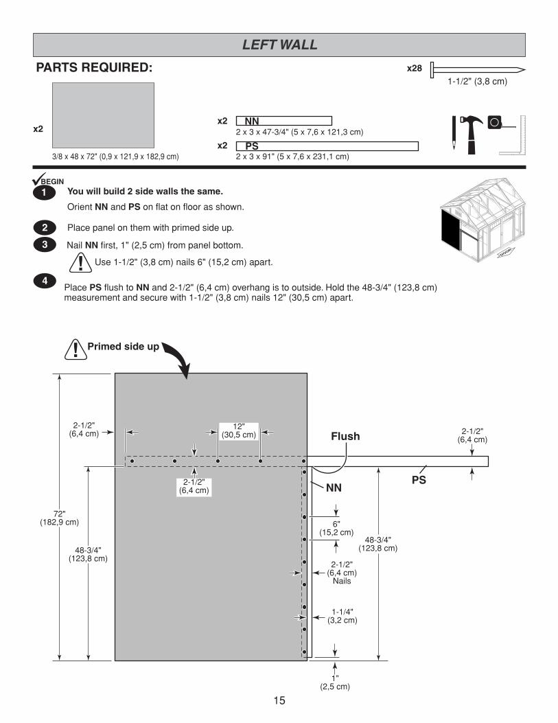
NailLRfirst.Holdthe1/2"(1,3cm)gap.
Use1-1/2"(3,8cm)nails6"(15,2cm)apart.
PlacePSflushtoLR and2-1/2"(6,4cm)overhangistooutside.Holdthe19-1/2"(49,5cm)measurementandsecurewith1-1/2"(3,8cm)nails6"(15,2cm)apart.
OrientLRandPSonflatonfloorunderassemblyasshown.
Flush

17
x54 1-1/2"(3,8cm)
19-1/2"(49,5cm)
2-1/2"(6,4cm)
1-1/2"(3,8cm) 2-1/2"
(6,4cm)
1"(2,5cm)
1"(2,5cm)
RKx42x3x13”(5x7,6x33cm)
PARTS REQUIRED:
SIDE WALLS
8
6"(15,2cm)
6"(15,2cm)
RK
Flush
Fig. A
48-3/4"(128,8cm)
12"(30,5cm)
2"(5,1cm)Nails
RK
x23/8x48x72"(1x121,9x182,9cm)
9
10
Use1-1/2"(3,8cm)nails6"(15,2cm)apartonedgesand12"(30,5cm)apartinside.
Placepanelflushtoattachedpanelwithprimedsideup.
PositionRKonedgeasshown(Fig. A).Securewiththree2"(5,1cm)nails.
RepeatSTEPS 1-9forothersidewall.
Youhavefinishedbuildingyoursidewalls
x122"(5,1cm)
FINISH
7

18
3"(7,6cm)
3"(7,6cm)Nails
PARTS REQUIRED:x2
x6
x2
x28
2x3x46-1/4"(5,1x7,6x117,5cm)
2x3x68”(5,1x7,6x172,7cm)
2x3x70-1/4"(5,1x7,6x178,4cm)
BACK WALL FRAME
NH
OT
OZ
FlushFlush
FlushFlush
70-1/4"(178,4cm)
70-1/4"(178,4cm)
116-1/2"(295,9cm)
46-1/4"(117,5cm)
46-1/4"(117,5cm)
22-1/4"(56,5cm)
22-1/4"(56,5cm)
24"(61cm)
24"(61cm)
24"(61cm)
68”(172,7cm)
OT x6
OZ NH
NH OZ
2 AttachOTatmarkswithtwo3"(7,6cm)nails,andfour3"(7,6cm)nailsangledatseamsasshown.
BEGIN
1̧ Orientpartsonedgeonfloorasshown.Measureandmark.
HINT: For easier nailing stand on frame.
SEAM
3"(7,6cm)Nails
NOTE: Dimensions are to center of studs.

19
46-1/8"(117,2 cm)
3/4"(1,9 cm)
3/4"(1,9 cm)
6"(15,2 cm)
12"(30,5 cm)
Flush
For squareness, maintain flush and3/4" measurement along panel edge.
4
5
3
PARTS REQUIRED: x452"(5,1cm)
BEGIN HERE
3/4" GAUGE BLOCK
BACK WALL
Primed side up
2 Nails
3/4" GAUGE BLOCK
Placethe46-1/8x72"(117,2x182,9cm)panelontowallframewithprimedsideupasshown.Usethegaugeblocktomarkthe3/4"(1,9cm)measurementonthewallstud.
Securepanelwithtwo2"nailsinthecorners(Fig. A).
Nailthepanelusing2"(5,1cm)nails6"(15,2cm)apartonedgesand12"(30,5cm)apartinsidepanel.
Ensure your wall frame is square by installing one panel and squaring frame.
Movetotheoppositeend.Usingthelongedgeofthepanelasalevermovethepanelside-to-sideuntilyouhavea3/4"(1,9cm)measurementonthewallstud.Securecornerwithtwo2"(5,1cm)nails(Fig. B).
Fig. B
Fig. A
3/4"(1,9cm)
3/4"(1,9cm)
2 Nails
x1
3/8x46-1/8x72"(1x117,2x182,9cm)

20
23-7/8"(60,6 cm)
3/4"(1,9 cm)
6"(15,2 cm)
46-1/8"(117,2 cm)
6"(15,2 cm)
12"(30,5 cm)
PARTS REQUIRED:
x1 x1
x712"(5,1cm)
3/8x46-1/8x72"(1x117,2x182,9cm)
3/8x23-7/8x72"(1x60,6x182,9cm)
BACK WALL
6 Place23-7/8"(60,6cm)panelonframeasshownwithprimedsidefacingup.
Nailusing2"(5,1cm)nails6"(15,2cm)apart.
Carefullyflipyourbackwallover.
Place46-1/8"(117,2cm)panelonframeasshownwithprimedsidefacingup.
Nailusing2"(5,1cm)nails6"(15,2cm)apartonedgesand12"(30,5cm)apartinsidepanel.
7
8
Youhavefinishedbuildingyourbackwall.FINISH
9
Primedside up
Primedside up
For squareness maintain fl ush along panel edges.
For squareness maintain fl ush along panel edges.
3/4" GAUGE BLOCK
3/4"(1,9cm)
3/4" GAUGE BLOCK

21
3"(7,6cm)
3"(7,6cm)Nails 3"(7,6cm)Nails
PARTSREQUIRED:x2
x2
x6
x1
x28
2x3x10-1/4"(5,1x7,6x26cm)
2x3x26-1/4"(5,1x7,6x66,7cm)
2x3x68”(5,1x7,6x172,7cm)
2x3x96"(5,1x7,6x243,8cm)
FRONT WALL FRAME
DJ
DG
OT
PT
FlushFlush
FlushFlushFlush Flush
Dimensions are to center of studs
Maintain dimensionsbetween studs
64"(162,6cm)
64"(162,6cm)
26-1/4"(66,7cm)
26-1/4"(66,7cm)
116-1/2"(296,2cm)
91"(231,1cm)25-1/2"
(64,8cm) 25-1/2"(64,8cm)
10-1/4"(26cm)
10-1/4"(26cm)
96"(243,8cm)
68”(172,7cm)
OT x6
DG DG
DJ DJPT
2 AttachOTatmarkswithtwo3"(7,6cm)nails,andfour3"(7,6cm)nailsangledatseamsasshown.
BEGIN
1̧ Orientpartsonedgeonfloorasshown.Measureandmark.
HINT:For easier nailingstand on frame.
Youhavefinishedbuildingyourfrontwallframe.
FINISH
3

22
x602"(5,1cm)
64"(162,6cm)
15-7/8"(40,3cm)
15-7/8"(40,3cm)
6"(15,2cm)
Placethe3/8x15-7/8x72"(1x40,3x182,9cm)panelontowallframeasshownwithprimedsideup.
Locatethepanelflushonthetopplateandstud.
3/8x15-7/8x72"(1x40,3x182,9cm)
3
2
1BEGIN
Securepanelstoframewith2"(5,1cm)nails6"apart.
Proceedtoattachingyourwingpanels.
Maintain dooropening
measurement
PARTS REQUIRED:
FRONT WALL
x2
Flush Flush
FlushFlush
6"(15,2cm)
FINISH
4
Primed side up Primed side up

23
x2
x583"(7,6cm)
64"(162,6cm)
10-1/4"(26cm)
10-1/4"(26cm)
6"(15,2cm)
6"(15,2cm)
PlacewingwallpanelsontoframewithtopofpanelsprimesideUPasshown.
Secureleftandrightwingpanelasshownusing2"(5,1cm)nails6"(15,2cm)apart.
3/8x10-1/4x72"(1x26x182,9cm)
UseOOasatemporarysupportasshownuntilwallisinstalled.Securewithtwo3"(6,6cm)screws.
Center
3"(7,6cm)screws
PARTS REQUIRED:
FRONT WALL
x2
Flush
OO
Flush
FlushFlush
Proceedtostandingyourbackwall.
OOx12x3x69"(5x7,6x175,3cm) 2"(5,1cm)
3
2
1BEGIN
FINISH
4
Primed side up Primed side up
Maintain dooropening
measurement

24
PARTS REQUIRED:
x1
x10
x23"(7,6cm)
3"(7,6cm)
BACK WALL INSTALLATION
OO
x21
2x3x69"(5,1x7,6x175,3cm)TemporarySupport
2"(5,1cm)
2"Nails(5,1cm)
3"(7,6cm)Nails
OO
OO
Fig. A
Fig. B
Angle to hitfl oor frame.
Angle to hitfl oor frame.
Secure 2" nails fi rst.
Secureframetofloorusingtwo3"(7,6cm)nailsbetweenwallstuds.Anglenailstohitfloorframe(Fig. B).
First,nailloweredgeofpaneltofloorframeusing2"(5,1cm)nails6"(15,2cm)apart.
Anglenailtohitfloorframe(Fig. A).
3
4
Youhavefinishedstandingyourbackwall.FINISH
5
Centerbackwallassemblyonthe116-1/2"(295,9cm)floordimension.
UseOOasatemporarybrace.Securewithtwo3"(7,6cm)screws.
2
BEGIN
1
3"Screws(7,6cm)
Temporary brace
116-1/2"(295,9cm)
6"(15,2cm)
2"Nails(5,1cm)

25
PARTS REQUIRED:
x6
x2
SIDE WALL INSTALLATION
x30
Fig. B
Fig. C
Fig. E
Fig. F
Fig. D
Fig. E
SameMeasurement
3"(7,6cm)Screws
6"(15,2cm)
6"(15,2cm)
2"(5,1cm)Nail
3"(7,6cm)Screws
Fig. A
3"(7,6cm)Screws
2"(5,1cm)Nail
3"(7,6cm)Nails
FINISH
4
Securethecenterstudusingtwo3"(7,6cm)screwsatanangleasshown(Fig. D).
Secureeachsidewallhorizontal2x3"intobackwallframeusingtwo3"(7,6cm)screwsatanangleateachconnectionasshown(Fig. E).
Securebothcleatsusingthree3"(7,6cm)nailsintofloor(Fig, F).
Securethelowersidewallcornertothebackwallstudwithone2"(5,1cm)nail(Fig. A).
Centerrightsidewallonfloor,side-to-side.
Besurethemeasurementbetweenthepaneledgesarethesamealongtheentirelength.Thensecurewithone2"(5,1cm)nailintheuppercorner(Fig. B).
Nailalongthepaneledgethroughthepanelintotheframeusing2"(5,1cm)nailsspaced6"apart.
Nailalongbottomofpanelusing2"(5,1cm)nails6"apart.Anglenailtohitfloorframe(Fig. C).
Youhavefinishedstandingyourrightwall.Proceedtostandtheleftwall.
1
2
3
StandrightsidewallassemblyonFloor.
It is important to secure the side wall in the following order.
BEGIN¸
2"(5,1cm)
3"(7,6cm)
3"(7,6cm)
CENTER
i2"(5,1cm)Nail

26
PARTS REQUIRED:
x6
x2
SIDE WALL INSTALLATION
x30
3"(7,6cm)
3"(7,6cm)
2"(5,1cm)
Fig. B
Fig. C
Fig. E
Fig. F
Fig. D
Fig. E
Same Measurement
3"(7,6cm)Screws
6"(15,2cm)
6"(15,2cm)
2"(5,1cm)Nail
3"(7,6cm)Screws
Fig. A
2"(5,1cm)Nail
3"(7,6cm)Screws
2"(5,1cm)Nail
3"(7,6cm)Nails
StandleftsidewallassemblyonFloor.
It is important to secure the side wall in the following order.
BEGIN¸
FINISH
4
Securethecenterstudusingtwo3"(7,6cm)screwsatanangleasshown(Fig. D).
Secureeachsidewallhorizontal2x3"intobackwallframeusingtwo3"(7,6cm)screwsatanangleateachconnectionasshown(Fig. E).
Securebothcleatsusingthree3"(7,6cm)nailsintofloor(Fig, F).
Securethelowersidewallcornertothebackwallstudwithone2"(5,1cm)nail(Fig. A).
Removetemporarybrace.
Centerleftsidewallonfloor,side-to-side.
Besurethemeasurementbetweenthepaneledgesarethesamealongtheentirelength.Thensecurewithone2"(5,1cm)nailintheuppercorner(Fig. B).
Nailalongthepaneledgethroughthepanelintotheframeusing2"(5,1cm)nailsspaced6"apart.
Nailalongbottomofpanelusing2"(5,1cm)nails6"apart.Anglenailtohitfloorframe(Fig. C).
Youhavefinishedstandingyourleftwall.Proceedtostandthefrontwall.
1
2
3
CENTER

27
FRONT WALL INSTALLATION
CENTER
FINISH
4
Securethesidewallframeintothefronttopplateateachcornerusingtwo3"(7,6cm)screwsatanangleasshown(Fig. D).
Securebottomplatetofloorusingtwo3"(7,6cm)nailsbetweeneachstudasshown(Fig. E).
Securesidewallcleatstofrontwallbottomplatesusinga3"(7,6cm)screwatanangleasshown(Fig. E).
Securethesidewallcenterhorizontalsupportusingtwo3"(7,6cm)screwsintofrontwallframeatanangleasshown(Fig. F).
RemovetemporarysupportOOafterwallisinstalled.
Youhavefinishedstandingyourfrontwall.
x8
x10
x44
64"(162,6cm)
Fig. C
Fig. D
Fig. F
Same Measurement
3"(7,6cm)Screws
3"(7,6cm)Screw
3"(7,6cm)Nails
Fig. B
2"(5,1cm)Nail
2"(5,1cm)Nail
2"(5,1cm)Nail2 Besurethemeasurementbetweenthe
paneledgesarethesamealongtheentirelength.Thensecurewithone2"(5,1cm)nailinthesidewalluppercorner(Fig. C).
Nailalongthesidewallpaneledgethroughthepanelintotheframeusing2"(5,1cm)nailsspaced6"(15,2cm)apart.
Repeatprocesstosecureothersideofthefrontwall.
Centerfrontwallonfloorside-to-side.
Checkthe64"(162,6cm)dooropeningisheldbeforenailing.
Securelowerfrontwallcornerstosidewallframeswithone2"(5,1cm)nail(Fig. A).
Nailthefrontwallflushtothefloorusing2"(5,1cm)nails6"(15,2cm)apart.Anglenailstohitfloorframe(Fig. B).
1
3
Angle to hitfl oor frame.
Fig. E
Fig. A
6"(15,2cm)
BEGIN
1̧
2"(5,1cm)
3"(7,6cm)
3"(7,6cm)
Standfrontwallonfloor.Itisimportanttosecurethefrontwallinthefollowingorder.
PARTS REQUIRED:
Angle to hitfl oor frame.
3"(7,6cm)Screws

28
DO
OR
3"(7,6cm)Nails
WALL DOUBLERS
PARTS REQUIRED:
FINISH
2 Youhavefinishedinstallingyourwalldoublers.
1BEGIN
Placepartsflushtoinsideoffrontandbacktopplates(Fig. A)andflushtowallpanels(Fig. B)asshown.
Secureusingtwo3"(7,6cm)nails24"(61cm)apartandatseamsasshown.
24"(61cm)apart
21-1/4"(54cm)
96"(243,8cm)
96"(243,8cm)
21-1/4"(54cm)
CR VX
VX
Flush
CR
x283"(7,6cm)
VXx22x6x96"(5,1x15,2x243,8cm)
CRx2 2x6x21-1/4"(5,1x15,2x54cm)
TOP VIEW Flush
Fig. B
END VIEWFlush
Fig. A

29
LOFT
PARTS REQUIRED:
1BEGIN
2
YouwillbuildtwoLofts.
PlaceLRflushtobottomoftopplatesatfrontandbackcornersasshown.Secureusing3"(7,6cm)nails.
PlacePSflushatendsofLR.Secureusing3"(7,6cm)nailsasshown).
x283"(7,6cm)
PSx22x3x91"(5,1x7,6x231,1cm)
LRx42x3x19"(5,1x7,6x48,3cm)
3"(7,6cm)Nails
3"(7,6cm)Nails PS
LRLR
Flush Flush
30
LOFT
PARTS REQUIRED:
FINISH
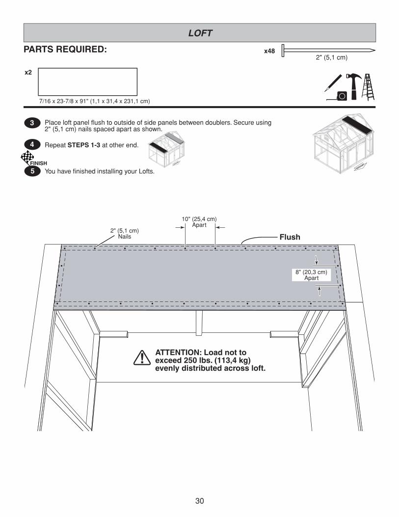
5 YouhavefinishedinstallingyourLofts.
4
3
RepeatSTEPS 1-3atotherend.
Placeloftpanelflushtooutsideofsidepanelsbetweendoublers.Secureusing2"(5,1cm)nailsspacedapartasshown.
x2
x482"(5,1cm)
2"(5,1cm)Nails
10"(25,4cm)Apart
8"(20,3cm)Apart
7/16x23-7/8x91"(1,1x31,4x231,1cm)
Flush
ATTENTION: Load not to exceed 250 lbs. (113,4 kg) evenly distributed across loft.
31
Fit base of Rafters in cornersof back wall
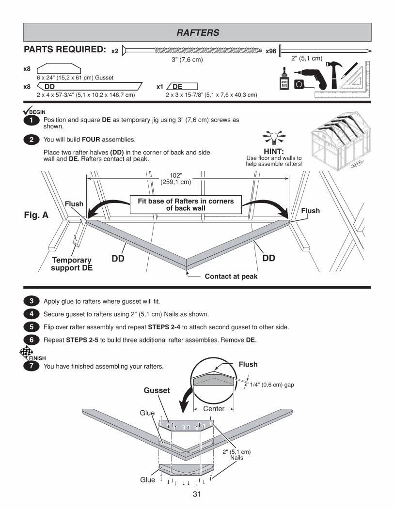
PARTS REQUIRED: x96
RAFTERS
FINISH
7 Youhavefinishedassemblingyourrafters.
Applygluetorafterswheregussetwillfit.
Securegussettoraftersusing2"(5,1cm)Nailsasshown.
FlipoverrafterassemblyandrepeatSTEPS 2-4 toattachsecondgussettootherside.
RepeatSTEPS 2-5tobuildthreeadditionalrafterassemblies.RemoveDE.
4
5
6
3
2
DDx82x4x57-3/4"(5,1x10,2x146,7cm)
x86x24"(15,2x61cm)Gusset
102"(259,1cm)
Glue
GlueCenter
1/4"(0,6cm)gapGusset
DDTemporarysupport DE
Fig. A
DD
Flush
Flush
Contact at peak
Flush
2"(5,1cm)Nails
2"(5,1cm)
YouwillbuildFOURassemblies.
Placetworafterhalves(DD)inthecornerofbackandsidewallandDE.Rafterscontactatpeak.
PositionandsquareDEastemporaryjigusing3"(7,6cm)screwsasshown.
BEGIN
1̧
DEx12x3x15-7/8”(5,1x7,6x40,3cm)
x23"(7,6cm)
HINT:Usefloorandwallstohelpassemblerafters!
32
22-5/8”(57,5 cm)
22-5/8”(57,5 cm)
24”(61 cm)
24”(61 cm)
24”(61 cm)
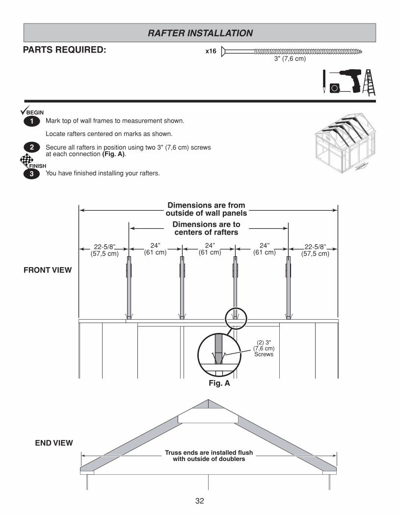
x16
Marktopofwallframestomeasurementshown.
Locaterafterscenteredonmarksasshown.
Secureallraftersinpositionusingtwo3"(7,6cm)screwsateachconnection(Fig. A).
1
2
FINISH
3 Youhavefinishedinstallingyourrafters.
3"(7,6cm)PARTS REQUIRED:
BEGIN
RAFTER INSTALLATION
(2)3"(7,6cm)Screws
Fig. A
END VIEW
FRONT VIEW
Truss ends are installed fl ushwith outside of doublers
Dimensions are tocenters of rafters
Dimensions are fromoutside of wall panels

33
GABLES
PARTS REQUIRED:
2
3
FINISH
4 Youhavefinishedmakingyourgables.
1BEGIN
Youwillassembletwogables.Orientpartsflatonfloorprimedsideupasshown.
SecurecentergablepaneltotwoDEandLFusing1-1/2"(3,8cm)nailsasshown.
Alignleftandrightgablepanelsflushtocentergablepanelandsecureusing1-1/2"(3,8cm)nailsasshown.
Aligntopgablepanelcenteredonmiddlegablepanelandsecureusing1-1/2"(3,8cm)nailsasshown.
RepeatSteps 1 - 3tobuildsecondgable.
1-1/2"(3,8cm)x42
4"(10,2cm)
1-1/4"(3,2cm)
1-1/4"(3,2cm)
2-1/2"(6,4cm)
6"(15,2cm)
PrimedsideUP
PrimedsideUP
PrimedsideUP
PrimedsideUPFlushFlush 1-1/4"(3,2cm)
1-1/4"(3,2cm)
x2 x2x2DE
LF
x4
x2
2x3x15-7/8"(5,1x7,6x40,3cm)
2x3x21-1/2"(5,1x7,6x54,6cm)
DEDE
LF
x2
3"(7,6cm)
3"(7,6cm)

34
GABLE INSTALLATION
2
FINISH
3 Youhavefinishedattachingyourgablepanelassemblies.
1BEGIN
Centergableassemblyonsidewall.DEisflushtotopofframe.
Securepaneltotopplateusing2"(5,1cm)nails6"(15,2cm)apart.
SecureDEtotopplateusing3"(7,6cm)screwsatanangleasshown.
RepeatSTEPS 1-2atoppositeside.
x42
x8 PARTS REQUIRED:
2"(5,1cm)
3"(7,6cm)
6"(15,2cm)
2"(5,1cm)Nails
Flush
Flush
Flush
3"(7,6cm)Screws

35
GABLE TRIM INSTALLATION
x36PARTS REQUIRED:1-1/4"(3,2cm)
CNx42x4x59-1/4”(5,1x10,2x150,5cm)
CN
CN
Flush
Flush to top of panel
1-1/4"(3,2cm)Screws
Fig. B
Youhavefinishedinstallingyourgabletrim.
InstallfrontgabletrimCNflushtotopofpanelandflushatpeak(Fig. A)asshown.
Securetowallusing1-1/4"screws7-1/4"apart.ScrewthroughpanelsintoCN (Fig A).
2
BEGIN
1̧1
Repeatabovestepstosecurethebackwallgabletrim.
3
FINISH
4

36
CP
CP
Fig. B
Flush to trim
Flush against panel
Level
x62"(5,1cm)
PlaceCPflushandleveltotrimoverseaminpanelsfromoutside.(Fig A).
Secureusing2"(5,1cm)finishnailsasshown(Fig B).
Repeatonoppositeside.
FINISH
3 Youhavefinishedinstallingyourgables.
1BEGIN
2
UPPER GABLE INSTALLATION
2"(5,1cm)Finishnails
PARTS REQUIRED:
x21x3x22-5/8”(2.5x7,6x57,5cm)
CP

37
ROOF PANELS
PARTS REQUIRED: x42"(5,1cm)
2
BEGIN
1̧
3/4" GAUGE BLOCK
Movetotheoppositeend.Usingthelongedgeofthepanelasalever,movethepanelside-to-sideuntilthetopcornerisflushtothepeak(Fig. C)andthereis9/16"(1,4cm)measurementtothegabletrim(Fig. D).Youmayneedtomoveyoursidewalltogetthe9/16"(1,4cm)measurement.Securepanelwithtwo2"(5,1cm)nailsinthecorners.
Youmustsquaretheroofbyattachingonepanelfirst.Youwillusethepanel'slongedgeasalevertobringyourroofintosquare.Commonlyknownas“racking”.
Roof panels may cause serious injury until securely fastened.
Attachthe48x96"(121,9x243,8cm)panelwiththeroughsideup(painted-gridlinesside)witha3/4"(1,9cm)measurementontherafter(Fig A)andthepanelflushatthepeak(Fig. B).Securepanelwithtwo2"(5,1cm)nailsinthecorners.
9/16"(1,4cm)
1-1/2"(3,8cm)
GableTrim
Fig. D
Fig. C
TwoNails
TwoNails
3/4"(1,9cm)
Flushat peak
Flushat peak
Fig. B
Fig. A
48"
(121,9cm)
Gauge Block
7/16x48x96”(1,1x121,9x243,8cm)
7/16x23-7/8x48”(1,1x60,6x121,9cm)
7/16x11-1/4x96”(1,1x28,6x243,8cm)
7/16x11-1/4x23-7/8”(1,1x28,6x60,6cm)
x2 x 2
x1 x 2

38
3/4"(1,9cm)
Gauge Block
Flushat peak
12"(30,5cm)
9/16"(1,4cm)
6"(15,2cm)
PARTS REQUIRED: x128
3/4" GAUGE BLOCK
Keepspacingbetweenthecenteroftheraftersattheloweredgeofthepanelandsecurewithone2"(5,1cm)nailintoeachrafter(Fig. E).Movetothetopofthepanelandkeepspacingbetweenthecenteroftherafters.Securewithone2"(5,1cm)nailintoeachrafter(Fig. E).Nailtheroofpanelusing2"(5,1cm)nails6"(15cm)apartonedgesand12"(30,5cm)apartinsidepanel.
Attach11-1/4x48"(28,6x121,9cm)roofpanelflushtofirstpanel,flushatpeakandwiththe9/16"(1,4cm)measurement(Fig. F, G).
Attachlowerroofpanelsflushtotheupperpanels with3/4"(1,9cm)measurementonrafter(Fig. I)andwitha9/16"(1,4cm)measurementatthegabletrim(Fig. J).
Nailtheroofpanelusingtwo2"(5,1cm)nails6"(15,2cm)onedgesand12"(30,5cm)aoartinsidepanels.
Repeatprocesstoattachpanelsontheoppositeside.
3
4
24"(61cm)
24"(61cm)
24"(61cm)
2"(5,1cm)Nails
Staggerseams
Flush
Flush
Flush
ROOF PANELS
Fig. E
Measurements are from outside of trim.
Fig. I
Fig. F
Fig. G
Fig. J
2"(5,1cm)
9/16"(1,4cm)
Flush
24-1/2"(62,2cm)
24-1/2"(62,2cm)

39
PARTS REQUIRED: x282"(5,1cm)
Placepartsflushtobottomofdoublerasshown(Fig, A).
Securewith2"(5,1cm)finishnails24"(61cm)apart.
BEGIN
1̧
2
FINISH
3 Youhavefinishedinstallingyourfasciatrim.
Repeatprocessonoppositeside.
FASCIA TRIM
x41x3x96"(2,5x7,6x243,8cm)
CT
CT
CT
x21x3x22"(2,5x7,6x55,9cm)
BE
BE
BE
24"(61cm)apart
2"(5,1cm)Finishnails
Flush with bottom of doubler
Angletopnailstohitdoubler
Fig. A

40
2x3x69"(5x7,6x175,3cm)
x2
x8
OO
HINT:Look for 3/8" SPACER
attached to doors.x1x1
Left Door Right Door
Orientpartsasshownonflatsurface.3/8" offset is to top. Look for red (right) and green (left) on hinge board.
PARTS REQUIRED:
BEGIN
1̧1
3"(5cm)
2 AttachtemporarysupportsOOwith3"screwsinmiddleandatends.Tightensecuely.
DOORS
OO
OO
Make sure spacer is attached.
Tighten screws securely.
OFFSET
GREEN RED
OFFSET
3"(7,6cm)Screws
3"(7,6cm)Screws
Bottom edges flush
3/8"(1cm)3/8"
(1cm)
3/8"(1cm)
3/8"(1cm)

41
PARTS REQUIRED: x133"(7,6cm)
Fig. D
Fig. C
Fig. E
Angle3"(7,6cm)Screw
Flush
Fig. B
3/8"(1cm)
DOORS
3
PT
72"(182,9cm)frompanelPT
Fig. A
Centerdoorsonmarkasshown(Fig. B).
4
5
6
Check hinge boards are fl ush under overhang (Fig. C).
Removetemporarysupportsandledgerboard.Checkdoorsopenproperly.
FINISH
7 Youhavefinishedinstallingyourdoors.
Measure72"(182,9cm)downfromundersideofdoubler(Fig. A).AttachPTasatemporaryledgerboardfordoorstoreston,usingthree3"(7,6cm)screws.
Locatecenterofdooropeningandmark.
72"(182,9cm)frombottomofpanelto
topofledgerboard
Mark32"(81,3cm)centerofopening
Screwhingeboardsintowallframeandfloorusing3"(7,6cm)screwsasshown.
Make sure screws go into framing and fl oor(Fig. D, E).
64"(162,6cm)
3" (7,6 cm)Screws
x1 PT2x3x96"(5,1x7,6x243,8cm)
Center 3/8" measurement on mark.

42
Door Trim
HingeBoard
Fig. B
DoorPanel
You have fi nished installing your door trim.FINISH
3
Fig. A
Flush to opening
Center Center
PARTS REQUIRED:
DOOR TRIM
Glue
Add glue to parts AH before
installing.
x483/4" (1,9 cm)
3/4" (1,9 cm)Screws
x219/32” x 2-1/2” x 26-5/8” (1,5 x 7,6 x 67,6 cm)
AH
Remove 3/8" (1 cm) spacers from doors.
Attach AH fl ush to door panel opening using fi ve 3/4" (1,9 cm) screws as shown. Reinforce the door trim using 3/4" (1,9 cm) screws through door panel into outer trim as shown (Fig. A, B).
2
BEGIN
1
AH
AH
43
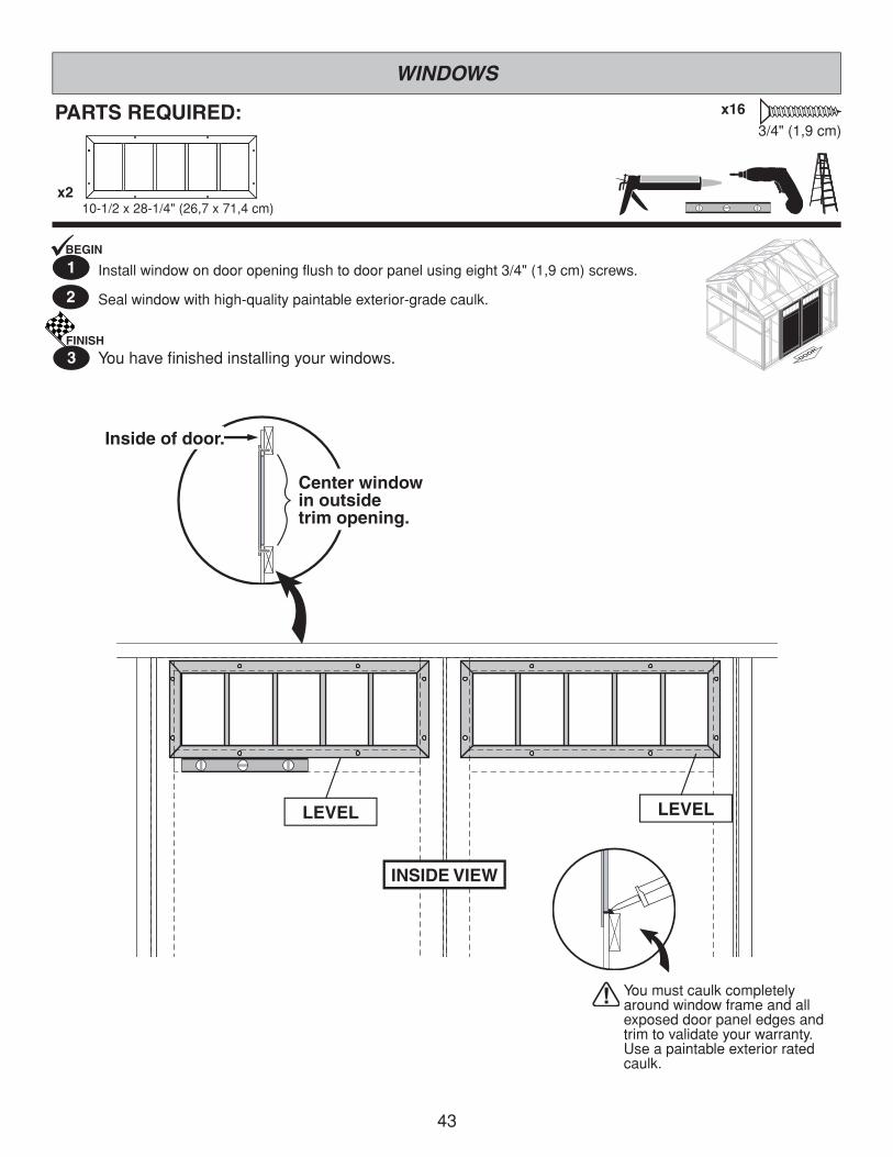
PARTS REQUIRED: x163/4"(1,9cm)
2
Installwindowondooropeningflushtodoorpanelusingeight3/4"(1,9cm)screws.
Sealwindowwithhigh-qualitypaintableexterior-gradecaulk.
WINDOWS
LEVELLEVEL
INSIDE VIEW
Inside of door.
Center window in outsidetrim opening.
Youmustcaulkcompletelyaroundwindowframeandallexposeddoorpaneledgesandtrimtovalidateyourwarranty.Useapaintableexteriorratedcaulk.
BEGIN
1̧1
FINISH
3 Youhavefinishedinstallingyourwindows.
10-1/2x28-1/4"(26,7x71,4cm)x2

44
Insideof Door
Drill 3/8" (1 cm) HoleIn-line with bolt.
2" (5,1 cm)x10
3/4"(1,9 cm)
x5
Flush
LEFT DOOR
OUTSIDE OF SHEDFlush
with top
Install onleft door.
Drill 3/8" (1 cm) HoleIn-line with bolt.
RIGHT DOOR
LEFTDOOR
Flush
2" Screws(5,1 cm)
3/4" (1,9 cm)Screws
7/8"(2,2 cm)
x2
3/4"(1,9cm)x13
3/8"(1cm)DrillBit
BEGIN
2
3 MountonebarrelboltflushattopofOOonleftdoorusing3/4"(1,9cm)screwsasshown(Fig B).Tapbarrelboltwithhammeranddrill3/8"(1cm)hole.
MountthesecondbarrelboltflushatbottomofOOonleftdoorusing3/4"(1,9cm)screwsasshown(Fig C).Tapbarrelboltwithhammeranddrilloutholeusing3/8"(1cm)DrillBit.
1
PARTS REQUIRED:
DOOR HARDWARE
2x3x69"(5,1x7,6x175,3cm)
x2
x2
OO
x10 2"(5,1cm)
CenterOObetweenfloorandtopplateandverticallyonthedoorflushtotheedgeofthedoor(Fig. A).Secureusingfive2"(5,1cm)screwsthroughoutsidetrimintoOO(Fig. A). Repeatonoppositedoor.
OrientweatherstriptooverlapOOasshownonLeftdoorusingfive3/4"(1,9cm)screws(Fig. A)
Fig. B
Fig. C
TOP PLATE
Fig. A
3/8x1-3/4x69"(1x6,3x175,3cm)
OO OO
Weatherstrip
Weatherstrip
OO
CE
NT
ER

45
3/8"(1cm)DrillBit
Fig. B
PARTS REQUIRED:
DOOR HARDWARE
1-1/2"(3,8cm)
SETSCREW
Flushto hinge
1-1/2"(3,8cm)
35-3/4"(90cm)
INSTALL ONRIGHT DOOR.
1-1/2"(3,8cm)
TOP VIEW
1/4" (0,6 cm) Pre-drill and1/2" (1,3 cm) Drill-through.DRILL FROM INSIDE.
x21-1/2"(3,8cm)
x21-1/2"(3,8cm)
YouhavefinishedinstallingyourT-handleandfauxhinges.
Measureandmarkpositionfordoorhandleasshown.Pre-drill1/4"(0,6cm)and1/2"(1,3cm)drill-through.DRILL FROM INSIDE.
4
FINISH
8
Attachpaddletohandleandsecurewithsetscrewasshown.6
Installdecorativehingesonhorizontaltrimandflushagainstpianohingeasshown.7
Inserthandleinholeandsecureusing1-1/2"(3,8cm)screws.5
3/4"(1,9cm)x12
x4 x1

46
SecurePTusingtwo3"(7,6cm)screwsateachendasshown.
Placeshelfpanelintogapflushagainstbackwall.Secureusing2'(5,1cm)nailsspaced10"(25,4cm)apart.
RepeatSTEPS 1-2onotherside.
Measureandmarkheightofhorizontal2x3"ontoinsideofstudandoutsideofofpanelasshown.Uselevel(Fig. A).
2
FINISH
3 Youhavefinishedinstallingyourshelves.
1BEGIN
SHELVES
PARTS REQUIRED:
x2
3”(7,6cm)
2”(5,1cm)
x8
x40
PT x2
x2
Floor
Insert into gap
SAME DIMENSION
HINT:Mark shelf support location
on outside of panel.
7/16x11-7/8x91"(1,1x60,6x231cm)
PT2x3x96"(5,1x7,6x243,8cm)
x2
7/16x11-7/8x91"(1,1x60,6x231cm)

47
PARTS REQUIRED: x12
Securecollartiestorafterwiththree2"(5,1cm)nailsateachend.2
FINISH
3 Youhavefinishedinstallingyourcollarties.
COLLAR TIES
BEGIN
1̧ Levelcollarties(JF)onbackofcenterraftersabovedoor.asshown
Checkcollartiesarelevelandflushtoroofpanels.
JFx21x4x60"(2,5x10,2x152,4cm)
2"(5,1cm)Nails
2"(5,1cm)Nails
2"(5,1cm)

48
PARTS REQUIRED:
FINISH
3
2
BEGIN
1̧ Locateandmarkfortwoventsinsidewallsasshown.
Cutoutmarkedopenings.
Caulkbehindventflanges.
Secureusing1/2"(1,3cm)screws.
Youhavefinishedinstallingyourvents.
x121/2"(1,3cm)
x2
VENTS
8x16"(20,3x35,6cm)
6"(15,2cm)
3–5"(7,6–12,7cm)
14"(35,6cm)
Caulk
Caulk
5"(12,7cm) 6"
(15,2cm)
7–8"(17,8–20,3cm)
14"(35,6cm)

49
2"(5,1cm)Nails
72"(182,9cm)
2"(5,1cm)
Overlapbattensatcorner(Fig. A).Positionbattensflushundereavesandtrim(Fig. B).BEGIN
Securebattenusing2"(5,1cm)finishnailsasshown.Caulkseambeforepainting.
Repeatonothercorners.
1
2
PARTS REQUIRED:
x8
x64
3/8x1-3/4x72"(1x4,5x183cm)
BATTENS
FINISH
3 Youhavefinishedinstallingyourcornerbattens.
Flush underpanel cutout
Fig. B
Fig. A
Flush undereave trim
2"(5,1cm)Finishnails
Seam is fl ush. Caulk seam before
painting trim.

50
•Installfeltflushtoallroofedgesoverlapping3".Useminimalamountofroofingnailstoholdinplace.
OK to overlap at ridge.3" OVERLAP Flush
Flush
PARTS REQUIRED:
•Useacryliclatexcaulkthatispaintable.Caulkatallhorizontalandverticalseams,betweenthetrimandwalls,andallaroundthedoortrim.
•Useahighqualityexterioracryliclatexpaint.Whenpaintingyourbuilding,thereareafewkeyareasthatcanbeeasilyoverlookedthatmustbepainted: •Bottomedgeofallsidingandtrim •Insideofdoorsandall4edges
Note: Primeallun-primedexteriorwoodbeforepainting. (Followdirectionsprovidedbymanufacturer.)
PAINT & CAULK-NOTINCLUDED-
ROOF FELT-NOTINCLUDED-
DRIP EDGE-NOTINCLUDED-
Snipbottomsideofdripedgeandbendovertoothersideofroof.
(Followdirectionsprovidedbymanufacturer.)
•Installdripedgeoverrooffeltongablesideandunderrooffeltoneaveside(Fig. A).•Donotusenailsonsideofdripedgethathangsoversideofbuilding.•Onlynailtopofdripedgeasshown.
Edge flush to trim.
Fig. ADrip edge
Roof felt
Dripedge

51
1"(2,5 cm)
NAILS
Sealing Strip 1"(2,5 cm)
1/2"(1,3 cm)
• Follow directions provided by manufacturer and these instructions.
SHINGLES -NOTINCLUDED-
Installfirststarterrowupsidedownandcolorupwitha1"overhangatbackandbottomofroofpanel.Use(4)nailspershingle.Starter row must be straight and level all the way across with lower edge of roof deck. NOTE:Ifyouhaveinstalleddripedgeinstallshinglesflushtodripedge.
BEGIN
1
TABS UP
Shingle overlaps roof decking.
1" (2,5 cm) overhang past roof deck.
1" (2,5 cm) overhang or flush with drip
edge.
(4) Nails
BACK OF SHED
FRONT OF SHED
NEVER DRIVE FASTENERS INTO OR ABOVE SEALING STRIPS.
Familiarize yourself with a 3-Tab Shingle.
SHINGLE NAIL PATTERN
Full Rain Slot
Half A Rain Slot
NotchNotch

52
1"(2,5cm)
1"(2,5cm)
1"(2,5cm)
SHINGLES continued...
Beginningatfrontofshed,installfirstrowofshingleswithnotchat1"pastroofedgeorflushwithdripedge.22
FRONT OF SHED BACK OF
SHED
Notch- or -
Drip Edge
Notch
Roof Deck
Flushwithstarterrow.
Flush with starter row.
Continueinstallingrowsofshinglesbystaggeringatfront.
4
Installsecondrowofshinglesflushattopoffirstrow'srainslots.Ensure1"overhangorflushtodripedgeatfront,staggereachrow.
3
BACK OF SHED
FRONT OF SHED
FRONT OF SHED
Flush with rain slots.Flush with rain slots.Flush with rain slots.Flush with rain slots.Flush with rain slots.Flush with rain slots.
Notch
Notch

53
Youhavefinishedshinglingyourroof.Proceedtocappingtheridge.FINISH
9
Continueinstallingrowsofshinglestothepeak.Atthepeakmakesurethereisamaximumof5"orlesstotherainslot,asshownbelow.Ifshinglesoverlapatridgecuttopeakwithautilityknife.
Repeatsteps1-6toshingletheoppositesideofyourroof.Trimshinglesatridge.
Oncebothsidesareshingledyouneedtotrimends.Strikeachalkline1"fromedge.
Usingyourshinglehookedbladecarefullycutshinglesalongchalkline.
5
6
7
8
SHINGLEScontinued...
• If more than 5" to rain slot you must install another row of shingles.
5"(12,7cm)orless.
5"(12,7cm)MAX.
Top of rain slot.
Cut Off. CUT

54
3
•Youwillfinishoffthetopoftheroofwitharidgecapmadefromshingles.
SHINGLES - RIDGE CAP
Note: •Youwillneedabout24-26cutpieces.
CutshinglesintoTHREEpieces.Hint:Usecut-offpiecesfirst.
Score shingle, then snap-off angled cut.
Installfirstridgecapflushtoshinglesatfront,asshown.
Installsecondridgecap5"back,asshown.
2
BEGIN
1
2"(5,1cm)
2"(5,1cm)
2"(5,1cm)
2"(5,1cm)
2"(5,1cm)
2"(5,1cm)
Top of slot.Weather Seal
Flush
(1) Nail per side through weather seal.
(1) Nail per side through weather seal.
5"(12,7cm)
FRONT OF SHED
Flush
24 to 26Pieces

SHINGLES - RIDGE CAPcontinued...
Continueinstallingridgecaptobackofroof.
Makesurethereis4"betweentheshingle-colorandedgeofshingles.
Whenyouhave4"minimumofshinglecolorcutonepiecetocapyourroof.
Installflushtoshingles.
4
5
6
7
(2) Nails per side.
Youhavefinishedyourridgecap.FINISH
8
Cut at top of rain slot.
Flush to shingles
Trim cap off fl ush to shingles
Cap
4"(10,2cm)
55

WARRANTYBackyard Storage Solutions, LLC warrants the following:1. Every product is warranted from defects in workmanship and manufacturing for one year.2. All hardware and metal components are warranted for two years.3. Trim is warranted for 12 years.4. Waferboard siding and sheathing is warranted for two years.5. SmartSide™ siding is warranted for 12 years.6. Timber series buildings’ siding and trim are warranted for 10 years.7. Solar Shed windows are warranted for 1 year.8. Cedar lumber is warranted for 15 years.9. Cedar doors and Cedar Garden Center are warranted for 10 years.10. Metal roof is warranted for 25 years.
Backyard Storage Solutions, LLC will repair, replace or pay for the affected part. In no event shall Backyard Storage Solutions, LLC pay the cost of labor or installation or any other costs related thereto. All warranties are from date of purchase. If a cash refund is paid on an affected part, it will be prorated from the date of purchase.
CONDITIONSThe warranty is effective only when:1. The unit has been erected in accordance with the assembly instructions. 2. The unit has been properly shingled and painted or stained and reasonably and regularly maintained thereafter.3. The failure occurs when the unit is owned by the original purchaser.4. Backyard Storage Solutions, LLC has received the warranty registration card within thirty (30) days of purchase and noti� ca- tion of the failure in writing within the warranty period speci fied above.5. Backyard Storage Solutions, LLC has had reasonable opportunity during the sixty (60) days following receipt of noti� cation to inspect and verify the failure prior to commencement of any repair work.
REQUIREMENTSStorage Buildings & PlayhousesTo validate your warranty, it is necessary to properly maintain your Backyard Storage Solutions, LLC unit; shingle the roof and paint or solid-colored stain the siding using 100% acrylic latex exterior product with a minimum of two (2) coats within sixty (60) days of assem-bly; caulk above all doors and all horizontal and vertical trim boards; paint and seal all exposed edges, sides and faces of SmartSide™ and waferboard siding to include all exterior walls and all sides and all edges of doors.
Gazebos, Pergolas & Timber BuildingsTo validate your warranty, it is necessary to properly maintain your Backyard Storage Solutions, LLC unit. This includes treating all of the exposed cedar and pine surfaces on your gazebo or timber building with an exterior grade wood preservative, an exterior oil-based semi-transparent stain, an acrylic latex exterior paint or an acrylic latex solid color exterior stain within 30 days of assembly and as needed thereafter to maintain your warranty.
Keep vegetation trimmed away from building and make sure siding panels and trim do not come in contact with masonry or cement. The minimum ground clearance for siding must be one half inch (½ inch) from concrete slab or two and one half inches (2 ½”) from the ground when building is erected or constructed on a treated wood floor kit. Water from sprinklers must be kept off unit. In no event will Backyard Storage Solutions, LLC be responsible for any indirect, incidental, consequential or special damages nor for failure(s) that are caused by events, acts or omissions beyond our control including, but not limited to, misuse or improper assembly, improper mainte-nance (which eventually leads to rot or decay) and acts of God. Backyard Storage Solutions, LLC will not be held responsible for any labor costs incurred to construct your unit.This warranty gives you certain speci fic rights that vary from state to state.
CLAIM PROCEDURETo make a claim under this warranty, you can either call 1-800-844-9273 or prepare a letter. Please have ready the information below when you call or include the information when writing:1. The model and size of the product.2. A list of the part(s) for which the claim is made.3. Proof of purchase of the Backyard Storage Solutions, LLC item, as shown on the original invoice.4. Run code, as listed on the yellow warranty card enclosed in the product package.
Mail the above information to: Backyard Storage Solutions, LLC Attn: Customer Service 1000 Ternes Monroe, MI 48162
Limited ConditionalWarranty *
*WARRANTY TERMS MAY VARY OUTSIDE THE U.S.A.IMPORTANT: This is your warranty certifi cate.Please complete and mail your warranty card to properly validate your warranty. ldr: 03/11/10