Embed Size (px)
Citation preview
STT250 / 150 Surge Protection Devices Series STT 3000 Specifications EN2I-6061 June 2005, Honeywell Part Number: 46188660-001
Introduction
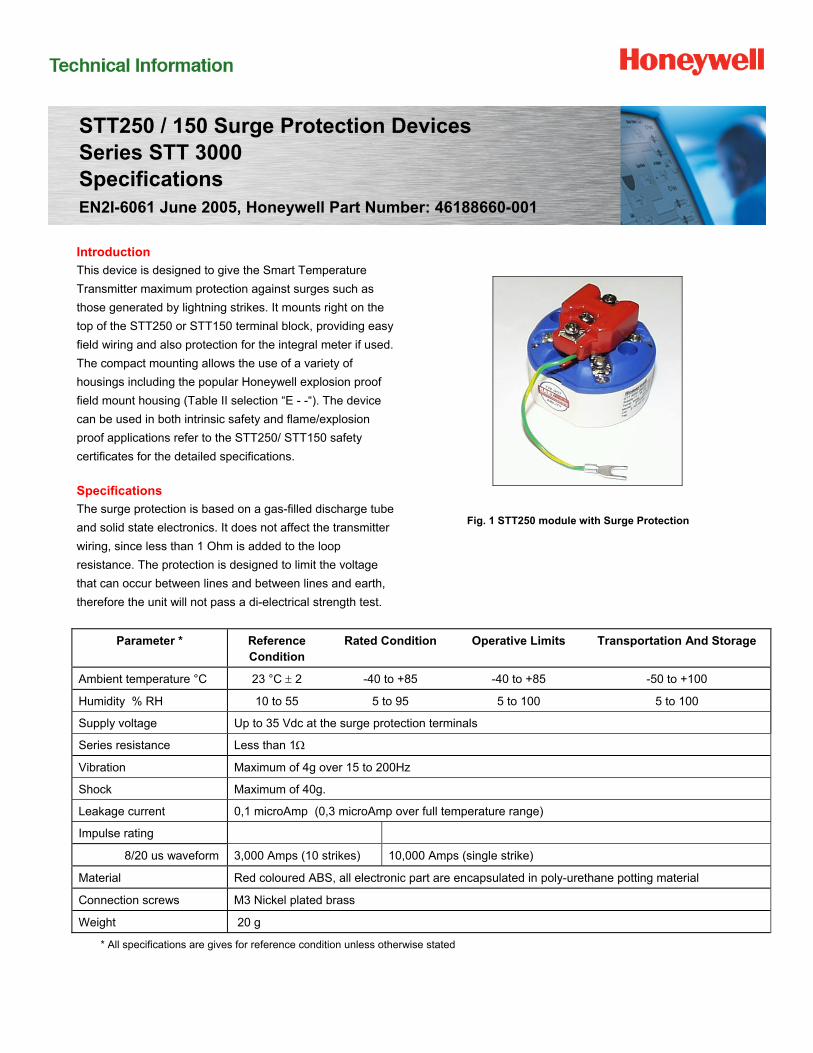
This device is designed to give the Smart Temperature
Transmitter maximum protection against surges such as
those generated by lightning strikes. It mounts right on the
top of the STT250 or STT150 terminal block, providing easy
field wiring and also protection for the integral meter if used.
The compact mounting allows the use of a variety of
housings including the popular Honeywell explosion proof
field mount housing (Table II selection “E - -“). The device
can be used in both intrinsic safety and flame/explosion
proof applications refer to the STT250/ STT150 safety
certificates for the detailed specifications.
Specifications
The surge protection is based on a gas-filled discharge tube
and solid state electronics. It does not affect the transmitter
wiring, since less than 1 Ohm is added to the loop
resistance. The protection is designed to limit the voltage
that can occur between lines and between lines and earth,
therefore the unit will not pass a di-electrical strength test.
Fig. 1 STT250 module with Surge Protection
Parameter * Reference Condition
Rated Condition Operative Limits Transportation And Storage
Ambient temperature °C 23 °C 2 -40 to +85 -40 to +85 -50 to +100
Humidity % RH 10 to 55 5 to 95 5 to 100 5 to 100
Supply voltage Up to 35 Vdc at the surge protection terminals
Series resistance Less than 1
Vibration Maximum of 4g over 15 to 200Hz
Shock Maximum of 40g.
Leakage current 0,1 microAmp (0,3 microAmp over full temperature range)
Impulse rating
8/20 us waveform 3,000 Amps (10 strikes) 10,000 Amps (single strike)
Material Red coloured ABS, all electronic part are encapsulated in poly-urethane potting material
Connection screws M3 Nickel plated brass
Weight 20 g
* All specifications are gives for reference condition unless otherwise stated
HFS Catalog_Without Tab_HighRes.pdf 1659 6/8/2011 12:42:15 PM
STT 3000Surge Protection Device 2
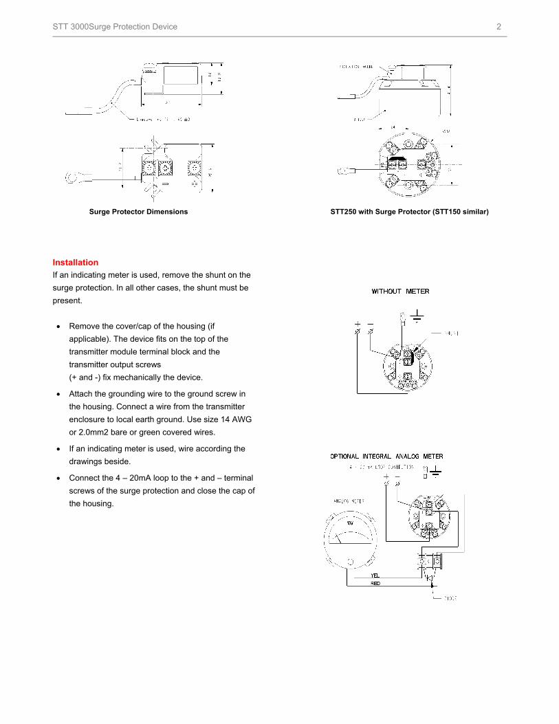
Surge Protector Dimensions STT250 with Surge Protector (STT150 similar)
Installation
If an indicating meter is used, remove the shunt on the
surge protection. In all other cases, the shunt must be
present.
Remove the cover/cap of the housing (if
applicable). The device fits on the top of the
transmitter module terminal block and the
transmitter output screws
(+ and -) fix mechanically the device.
Attach the grounding wire to the ground screw in
the housing. Connect a wire from the transmitter
enclosure to local earth ground. Use size 14 AWG
or 2.0mm2 bare or green covered wires.
If an indicating meter is used, wire according the
drawings beside.
Connect the 4 – 20mA loop to the + and – terminal
screws of the surge protection and close the cap of
the housing.
HFS Catalog_Without Tab_HighRes.pdf 1660 6/8/2011 12:42:15 PM
STT 3000Surge Protection Device 3
For More Information
Learn more about how Honeywell’s STT250 / 150
Surge Protection Device is designed to assure
maximum protection against surges, visit our website
www.honeywell.com/ps/hfs or contact your
Honeywell account manager.
Honeywell Process Solutions
1860 West Rose Garden Lane
Phoenix, Arizona 85027
Tel: 1-800-423-9883 or 1-800-343-0228
www.honeywell.com/ps/
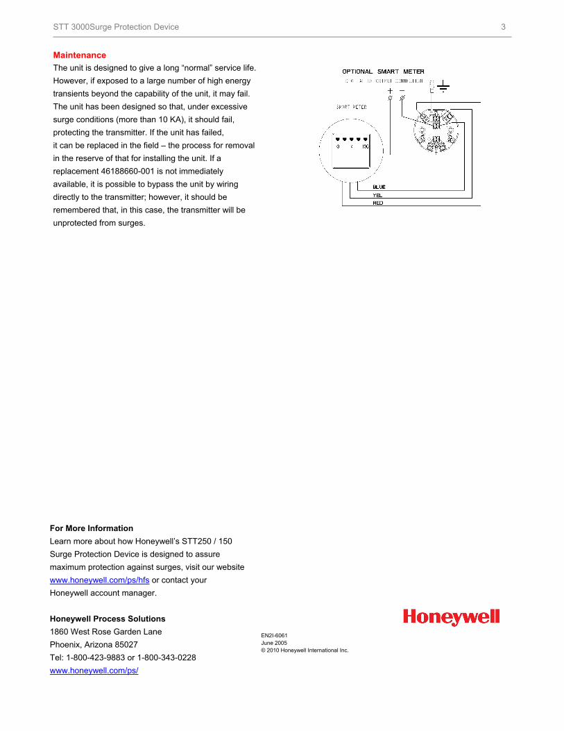
Maintenance
The unit is designed to give a long “normal” service life.
However, if exposed to a large number of high energy
transients beyond the capability of the unit, it may fail.
The unit has been designed so that, under excessive
surge conditions (more than 10 KA), it should fail,
protecting the transmitter. If the unit has failed,
it can be replaced in the field – the process for removal
in the reserve of that for installing the unit. If a
replacement 46188660-001 is not immediately
available, it is possible to bypass the unit by wiring
directly to the transmitter; however, it should be
remembered that, in this case, the transmitter will be
unprotected from surges.
EN2I-6061 June 2005 © 2010 Honeywell International Inc.
HFS Catalog_Without Tab_HighRes.pdf 1661 6/8/2011 12:42:15 PM