Embed Size (px)
Citation preview

Honeywell Process Solutions
STT700 SmartLine Temperature Transmitter
User’s Manual
34-TT-25-17
Revision 5
July 2019

Revision 5 STT700 Temperature Transmitter User’s Manual Page ii
Copyrights, Notices and Trademarks
© Copyright 2019 by Honeywell, Inc.
Revision 5, July 2019
While the information in this document is presented in good faith and believed to be
accurate, Honeywell disclaims any implied warranties of merchantability and fitness for a
particular purpose and makes no express warranties except as may be stated in the written
agreement with and for its customers. In no event is Honeywell liable to anyone for any
indirect, special, or consequential damages. The information and specifications in this
document are subject to change without notice.
Honeywell, TDC 3000, SFC, SmartLine, PlantScape, Experion PKS, and TotalPlant are
registered trademarks of Honeywell International Inc. Other brand or product names are
trademarks of their respective owners.
Honeywell Process Solutions 1250 W Sam Houston Pkwy S
Houston, TX 77042

Revision 5 STT700 Temperature Transmitter User’s Manual Page iii
About This Manual
This manual is a detailed how to reference for installing, piping, wiring, configuring, starting up,
operating, maintaining, calibrating, and servicing Honeywell’s family of STT700 temperature
transmitters. Users who have a Honeywell STT700 SmartLine Temperature Transmitter
configured for HART protocol or Honeywell’s Digitally Enhanced (DE) are referred to the
STT700 SmartLine Series HART/DE Option User’s Manual, document number 34-TT-25-18.
The configuration of your transmitter depends on the mode of operation and the options selected
for it with respect to operating controls, displays and mechanical installation. This manual
provides detailed procedures to assist first-time users, and it further includes keystroke
summaries, where appropriate, as quick reference or refreshers for experienced personnel.
To digitally integrate a transmitter with one of the following systems:
• For the Experion PKS, you will need to supplement the information in this document with the
data and procedures in the Experion Knowledge Builder.
• For Honeywell’s TotalPlant Solutions (TPS), you will need to supplement the information in this
document with the data in the PM/APM SmartLine Transmitter Integration Manual, which is
supplied with the TDC 3000 book set. (TPS is the evolution of the TDC 3000).
Release Information:
STT700 SmartLine Temperature Transmitter User Manual, Document # 34-TT-25-17,
Rev.1 July 2017 1st Release
Rev.2 February 2018 FM Approval updates
Rev.3 October 2018 CCoE, NEPSI, SAEx approvals added.
Sensor Wiring Best Practice Recommendations added
Rev.4 December 2018 Voltage resistance chart updated. Dimensions added.
Rev.5 July 2019 Integral Meter, Head mount Enclosure and DE Start-up fix
Page iv STT700 Temperature Transmitter User’s Manual Revision 5
References
The following list identifies publications that may contain information relevant to the information
in this document.
• STT700 SmartLine Temperature Transmitter Quick Start Installation Guide, Document
# 34-TT-25-19
• STT700 SmartLine Temperature Transmitter HART/DE Option User’s Manual,
Document # 34-TT-25-18
• STT700 SmartLine Temperature Field Device Spec (HART), Document # 34-TT-00-05
• STT700 SmartLine Transmitter Safety manual Document # 34-TT-25-20
• MC Toolkit User Manual, MCT404, Document # 34-ST-25-50
• Engineering Meter (EU) User Guide, Document #34-ST-25-18
• STT700 Series Temperature, Transmitter, Agency IS Control Drawing #50133855
• Smart Field Communicator Model STS 103 Operating Guide, Document # 34-ST-11-14
(for use with STT700 DE only)
Patent Notice
The Honeywell STT700 SmartLine Temperature Transmitter family is covered by one or more of the
following U. S. Patents: 5,485,753; 5,811,690; 6,041,659; 6,055,633; 7,786,878; 8,073,098; and other
patents pending.
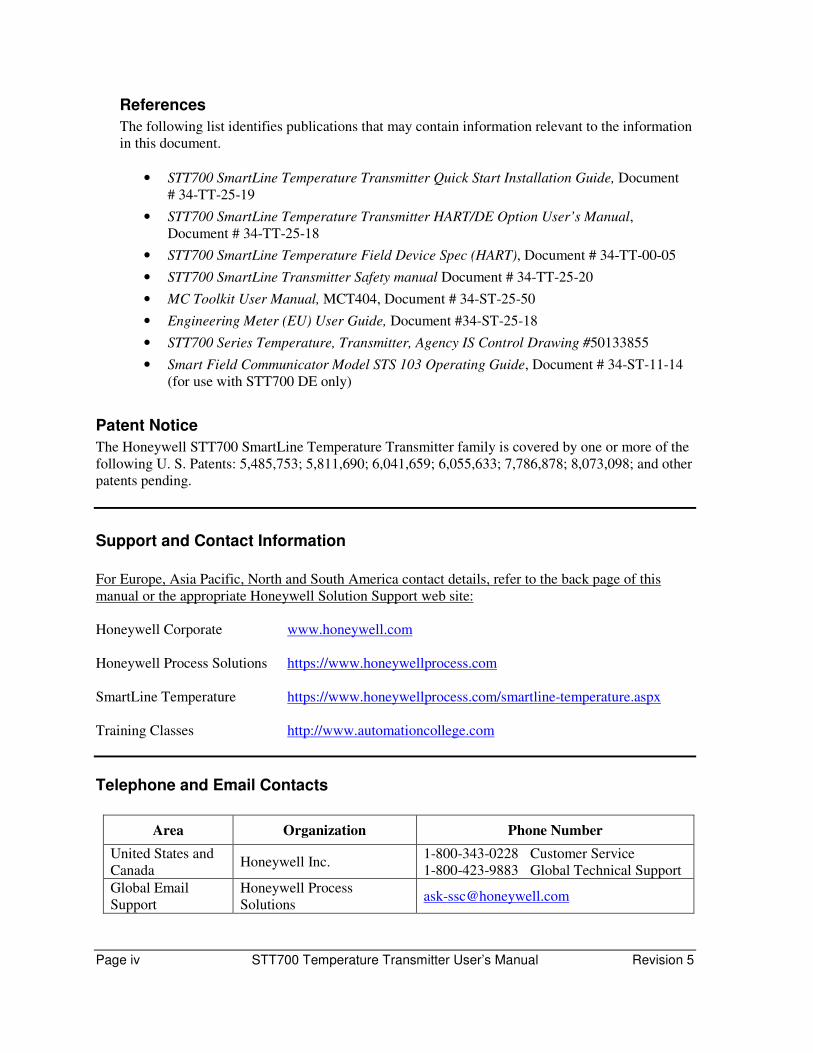
Support and Contact Information
For Europe, Asia Pacific, North and South America contact details, refer to the back page of this
manual or the appropriate Honeywell Solution Support web site:
Honeywell Corporate www.honeywell.com
Honeywell Process Solutions https://www.honeywellprocess.com
SmartLine Temperature https://www.honeywellprocess.com/smartline-temperature.aspx
Training Classes http://www.automationcollege.com
Telephone and Email Contacts
Area Organization Phone Number
United States and
Canada Honeywell Inc.
1-800-343-0228 Customer Service
1-800-423-9883 Global Technical Support
Global Email
Support
Honeywell Process
Solutions [email protected]

Revision 5 STT700 Temperature Transmitter User’s Manual Page v
Symbol Descriptions and Definitions
The symbols identified and defined in the following table may appear in this document.
Symbol Definition
ATTENTION: Identifies information that requires special consideration.
TIP: Identifies advice or hints for the user, often in terms of performing a task.
CAUTION Indicates a situation which, if not avoided, may result in equipment or work (data) on the system being damaged or lost, or may result in the inability to
properly operate the process.
CAUTION: Indicates a potentially hazardous situation which, if not avoided, may result in minor or moderate injury. It may also be used to alert against
unsafe practices.
CAUTION symbol on the equipment refers the user to the product manual for additional information. The symbol appears next to required information in
the manual.
WARNING: Indicates a potentially hazardous situation, which, if not avoided, could result in serious injury or death.
WARNING symbol on the equipment refers the user to the product manual for additional information. The symbol appears next to required information
in the manual.
WARNING, Risk of electrical shock: Potential shock hazard where HAZARDOUS LIVE voltages greater than 30 Vrms, 42.4 Vpeak, or 60 VDC
may be accessible.
ESD HAZARD: Danger of an electro-static discharge to which equipment may be sensitive. Observe precautions for handling electrostatic sensitive
devices.
Protective Earth (PE) terminal: Provided for connection of the protective earth (green or green/yellow) supply system conductor.
Functional earth terminal: Used for non-safety purposes such as noise immunity improvement. NOTE: This connection shall be bonded to
Protective Earth at the source of supply in accordance with national local electrical code requirements.
Earth Ground: Functional earth connection. NOTE: This connection shall be bonded to Protective Earth at the source of supply in accordance with
national and local electrical code requirements.
Chassis Ground: Identifies a connection to the chassis or frame of the equipment shall be bonded to Protective Earth at the source of supply in
accordance with national and local electrical code requirements.
continued

Page vi STT700 Temperature Transmitter User’s Manual Revision 5
Symbol Description
The Factory Mutual® Approval mark means the equipment has been rigorously tested and certified to be reliable.
The Canadian Standards mark means the equipment has been tested and meets applicable standards for safety and/or performance.
The Ex mark means the equipment complies with the requirements of the European standards that are harmonized with the 94/9/EC Directive (ATEX Directive, named after the French "ATmosphere EXplosible").

Revision 5 STT700 Temperature Transmitter User’s Manual Page vii
Contents
1. Introduction .................................................................................................................................... 1
Overview ................................................................................................................................ 1
Features and Options .............................................................................................................. 1
Physical Characteristics .................................................................................................. 2
Functional Characteristics .............................................................................................. 3
STT700 SmartLine Transmitter Nameplate ........................................................................... 3
Safety Certification Information ............................................................................................. 4
Transmitter Adjustments ........................................................................................................ 4
EU Meter Option – HART only ............................................................................................. 4
2. Application Design ......................................................................................................................... 5
Overview ................................................................................................................................ 5
Safety ...................................................................................................................................... 5
Accuracy ......................................................................................................................... 5
Diagnostic Messages ...................................................................................................... 5
3. Installation and Startup ................................................................................................................... 9
Installation Site Evaluation ..................................................................................................... 9
Honeywell MC Toolkit........................................................................................................... 9
Mounting and Dimensions ................................................................................................... 10
DIN Rail Mounting ....................................................................................................... 10
Mounting Module in Housing ...................................................................................... 11
Dimensions ................................................................................................................... 13
Spring Loading ............................................................................................................. 15
Installation Procedure of Standard display for STT700: ...................................................... 16
Uninstalling/Installing Standard Display for external wiring ....................................... 16
Wiring a transmitter .............................................................................................................. 22
Loop Power Overview .................................................................................................. 22
Digital System Integration Information ........................................................................ 24
Wiring Variations ......................................................................................................... 24
Grounding and Lightning Protection ............................................................................ 25
Input Sensor Wiring ..................................................................................................... 25
Lightning Protector ....................................................................................................... 27
4. Startup .......................................................................................................................................... 31
Overview ...................................................................................................................... 31
Startup Tasks ................................................................................................................ 31
Output Check Procedures ............................................................................................. 31
Constant Current Source Mode Procedure ................................................................... 32
5. Operation ...................................................................................................................................... 34
Overview .............................................................................................................................. 34
Configuration Tools.............................................................................................................. 34
Smart Field Communicator (SFC) for DE Models ....................................................... 34
HART Communicator Model 375, 475 or MC Toolkit FDC for HART 7 Models .... 35

Page viii STT700 Temperature Transmitter User’s Manual Revision 5
6. Maintenance ................................................................................................................................. 37
Overview .............................................................................................................................. 37
Preventive Maintenance Practices and Schedules ................................................................ 37
Troubleshooting ................................................................................................................... 37
Troubleshooting with SFC ........................................................................................... 37
Troubleshooting with HART communicator ............................................................... 39
Recommended Parts ............................................................................................................. 40
Wiring and Installation Drawings ........................................................................................ 43
Upgrading the firmware ....................................................................................................... 44
7. Calibration .................................................................................................................................... 48
Recommendations for transmitter Calibration ..................................................................... 48
Calibration Procedures ......................................................................................................... 48
Appendix A. PRODUCT CERTIFICATIONS .................................................................................... 49
Glossary ............................................................................................................................................... 64
List of Tables
Table 1 – Features and Options.............................................................................................................. 1
Table 2 – Available EU Meter Characteristics ...................................................................................... 4
Table 3 – STT700 Diagnostic Messages ................................................................................................ 6
Table 4 – STT700 Standard Non-Critical Diagnostics Messages .......................................................... 6
Table 5 - Dimension table for use with Figure 6 and Figure 7 ............................................................ 12
Revision 5 STT700 Temperature Transmitter User’s Manual Page ix
List of Figures
Figure 1: STT700 Temperature Transmitter device with display module ............................................. 2
Figure 2 – STT700 HART (left) and DE (right) Transmitter module .................................................... 2
Figure 3 – Nameplate on the side of the transmitter............................................................................... 3
Figure 4 –STT700 Model Number Format ............................................................................................ 3
Figure 5 - DIN Rail Mounting .............................................................................................................. 10
Figure 6 - Wall Mounting Dimensions ................................................................................................. 11
Figure 7 - Pipe Mounting Dimensions ................................................................................................. 12
Figure 8 – STT700 transmitter module with lightning protection (top) and without (bottom) ............ 13
Figure 9: Housing cover and O-ring ..................................................................................................... 14
Figure 10 - Spring Loading and Sensor Assembly ............................................................................... 15
Figure 11: : Position of Standard display for external wiring ............................................................. 17
Figure 12: Assembly of Standard display with Bracket ....................................................................... 18
Figure 13: short cable and display assembly ....................................................................................... 18
Figure 14: Cable joint fixed in the bracket ........................................................................................... 19
Figure 15: Long cable connection with STT Module ........................................................................... 19
Figure 16: Positioning of Long cable in the IM Housing ..................................................................... 20
Figure 17: : Example of external wiring (Reference only) ................................................................... 20
Figure 18 – STT700 with HART Transmitter Operating Ranges ........................................................ 22
Figure 19– STT700 with DE Transmitter Operating Ranges ............................................................... 22
Figure 20 –STT700 module terminal connections ............................................................................... 23
Figure 21 – HART/DE Input Wiring Diagram for single sensor connection ....................................... 26
Figure 22 – Wiring Diagram for HART Dual Sensor Connections ..................................................... 26
Figure 23 – STT700 with Lightning Protector Dimensions ................................................................. 27
Figure 24 – Installation without EU Meter ........................................................................................... 28
Figure 25 – Installation with EU Meter ................................................................................................ 29
Figure 26 – Installation with Standard Display .................................................................................... 29
Figure 27 – Current Loop Test Connections ........................................................................................ 32
Figure 27: Housing with EU meter ...................................................................................................... 41
Figure 28: Housing without EU meter ................................................................................................. 41
Figure 29: HOUSING WITH STANDARD DISPLAY ....................................................................... 42
Figure 30: HOUSING WITHOUT STANDARD DISPLAY .............................................................. 42


Revision 5 STT700 temperature transmitter User’s Manual Page 1
1. Introduction
Overview This section is an introduction to the physical and functional characteristics of Honeywell’s STT700
SmartLine Temperature Transmitter.
Features and Options The STT700 SmartLine Temperature Transmitter is available in a variety of models for measuring
Thermocouples, RTD, Millivolts, and ohm sensor types. Table 1 lists the protocols, Human-Machine
Interface (HMI), materials, approvals, and mounting bracket options for the STT700.
Table 1 – Features and Options
Feature/Option Standard/Available Options
Communication Protocols HART version 7
Digitally Enhanced (DE)
Human-Machine Interface (HMI)
Options
No Display
Standard Display
Calibration Single
Approvals (See Appendix A for details.) ATEX, CSA, FM, IECEx, CCoE, NEPSI, SAEx
Mounting Brackets Pipe mounting and wall mounting brackets in carbon
steel and 316 stainless steel.
Integration Tools DD or DTM Hosts such as Experion and FDM
Firmware Upgrade SAT tool for firmware upgrade

Page 2 STT700 Temperature Transmitter User’s Manual Revision 5
Physical Characteristics
As shown in Figure 1 and Error! Reference source not found., the STT700 is packaged in a single
module. The elements in this module are connected to the process sensors, measure the process
variables, respond to setup commands and execute the software and protocol for the different
temperature measurement types.
Figure 1: STT700 Temperature Transmitter device with display module
Figure 2 – STT700 HART (left) and DE (right) Transmitter module
Revision 5 STT700 Temperature Transmitter User’s Manual Page 3
Functional Characteristics
The transmitter measures process temperature and outputs a signal proportional to the measured
process variable (PV). Available output communication protocols include 4 to 20mA, Honeywell
Digitally Enhanced (DE) and HART protocols.
In addition, a Honeywell Multi-Communication (MC) Toolkit (not supplied with the transmitter) can
facilitate setup and adjustment procedures in the case of HART and DE. Certain adjustments can be
made through an Experion Station or a Universal Station if the transmitter is digitally integrated with
Honeywell’s Experion or TPS/TDC 3000 control system for HART and DE transmitters.
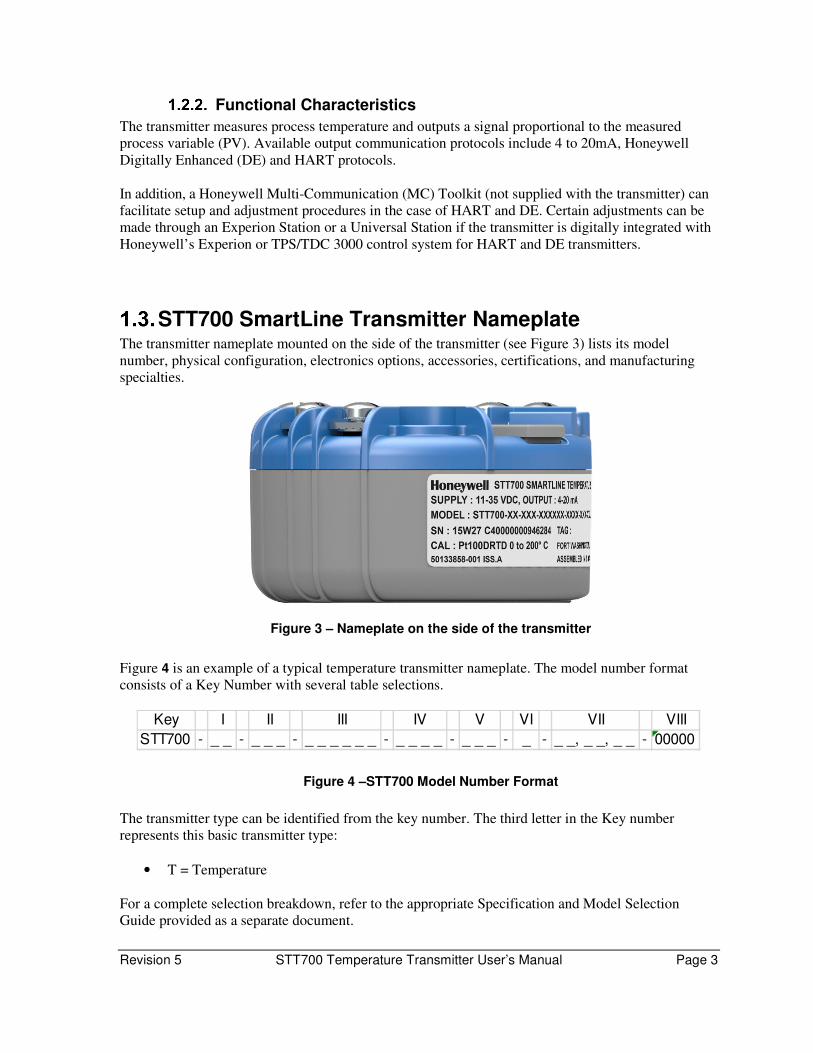
STT700 SmartLine Transmitter Nameplate The transmitter nameplate mounted on the side of the transmitter (see Figure 3) lists its model
number, physical configuration, electronics options, accessories, certifications, and manufacturing
specialties.
Figure 3 – Nameplate on the side of the transmitter
Figure 4 is an example of a typical temperature transmitter nameplate. The model number format
consists of a Key Number with several table selections.
Figure 4 –STT700 Model Number Format
The transmitter type can be identified from the key number. The third letter in the Key number
represents this basic transmitter type:
• T = Temperature
For a complete selection breakdown, refer to the appropriate Specification and Model Selection
Guide provided as a separate document.
Key I II III IV V VI VII VIII
STT700 - _ _ - _ _ _ - _ _ _ _ _ _ - _ _ _ _ - _ _ _ - _ - _ _, _ _, _ _ - 00000

Page 4 STT700 Temperature Transmitter User’s Manual Revision 5
Safety Certification Information The hazardous area approvals information is listed on the nameplate which, as shown in Figure 3, is
located at the bottom of the module. The approvals nameplate contains information and service
marks that disclose the transmitter compliance information. Refer to Appendix A of this document for
safety certification requirements and details.
Transmitter Adjustments For HART and DE you can use the Honeywell MC Toolkit or other third-party hand-held (for
HART) to make any adjustments to an STT700 SmartLine Temperature Transmitter.
Any HART 7.0 compliant PC host like Honeywell FDM can be used to configure the device.
Honeywell FDM can also configure the STT700 with DE protocol.
Alternately, certain adjustments can be made through the Experion or Universal Station, if the
transmitter is digitally integrated with a Honeywell Experion or TPS system.
EU Meter Option – HART only The STT700 SmartLine Temperature Transmitter can be supplied with the optional EU Meter, see Table 2.
Table 2 – Available EU Meter Characteristics
EU Meter (HART only)
• Compatibility for replacement of existing STT250 installations
• 360o rotation in 90o increments
• Standard units of measurement: °F, °C, °R, K, Ω, mV & %
EU Meter inside housing

Revision 5 STT700 Temperature Transmitter User’s Manual Page 5
2. Application Design
Overview This section discusses the considerations involved with deploying a Honeywell STT700 SmartLine
Temperature Transmitter in a process system. The following areas are covered:
• Safety
• Input and output data
• Reliability
• Environmental limits
• Installation considerations
• Operation and maintenance
• Repair and replacement
Safety
Accuracy
The STT700 SmartLine Temperature Transmitter accurately measures the temperature of a process
and reports the measurement to a receiving device like a controller I/O module. Refer to STT700
Specification, 34-TT-03-19, for complete accuracy specifications.
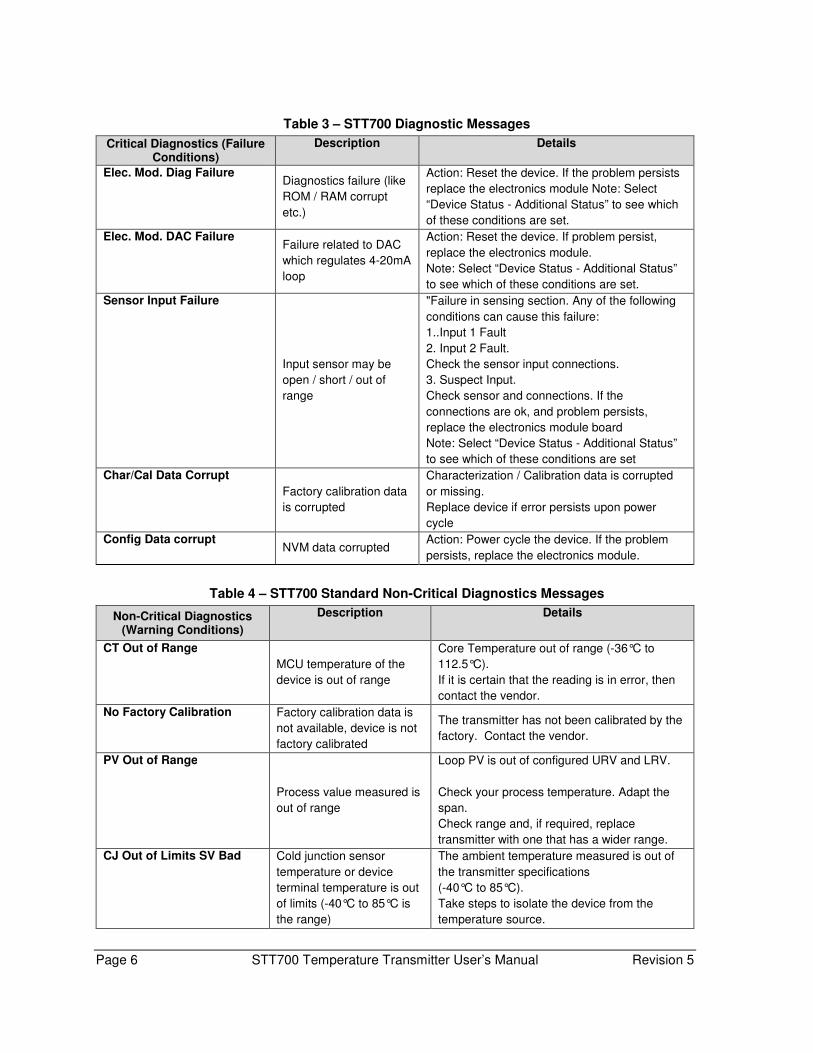
Diagnostic Messages
The transmitter standard diagnostics are reported in the two basic categories: critical and non-critical
faults. Problems detected as critical diagnostics drive the analog output to the programmed burnout
level for HART and DE. Tables 3 and 4, below, list the diagnostics and how faults are handled by the
STT700 transmitter. Refer to the Troubleshooting section for further details.
Table 3 show specific diagnostics to the transmitter, exclusive of those associated with HART and
DE protocols. HART and DE diagnostic messages are listed and described in the STT700 SmartLine
Temperature Transmitter HART/DE Option User Manual, document number 34-TT-25-18.
See Safety Integrity Level (SIL)
STT700 is intended to achieve sufficient integrity against systematic errors by the manufacturer’s
design. A Safety Instrumented Function (SIF) designed with this product must not be used at a SIL
level higher than the statement, without “prior use” justification by the end user or diverse technology
redundancy in the design. Refer to the STT700 Safety Manual, 34-TT-25-20, for additional
information. The DE variant of STT700 is not SIL certified.
Page 6 STT700 Temperature Transmitter User’s Manual Revision 5
Table 3 – STT700 Diagnostic Messages
Critical Diagnostics (Failure Conditions)
Description Details
Elec. Mod. Diag Failure Diagnostics failure (like
ROM / RAM corrupt
etc.)
Action: Reset the device. If the problem persists
replace the electronics module Note: Select
“Device Status - Additional Status” to see which
of these conditions are set.
Elec. Mod. DAC Failure Failure related to DAC
which regulates 4-20mA
loop
Action: Reset the device. If problem persist,
replace the electronics module.
Note: Select “Device Status - Additional Status”
to see which of these conditions are set.
Sensor Input Failure
Input sensor may be
open / short / out of
range
"Failure in sensing section. Any of the following
conditions can cause this failure:
1..Input 1 Fault
2. Input 2 Fault.
Check the sensor input connections.
3. Suspect Input.
Check sensor and connections. If the
connections are ok, and problem persists,
replace the electronics module board
Note: Select “Device Status - Additional Status”
to see which of these conditions are set
Char/Cal Data Corrupt
Factory calibration data
is corrupted
Characterization / Calibration data is corrupted
or missing.
Replace device if error persists upon power
cycle
Config Data corrupt NVM data corrupted
Action: Power cycle the device. If the problem
persists, replace the electronics module.
Table 4 – STT700 Standard Non-Critical Diagnostics Messages
Non-Critical Diagnostics (Warning Conditions)
Description Details
CT Out of Range
MCU temperature of the
device is out of range
Core Temperature out of range (-36°C to
112.5°C).
If it is certain that the reading is in error, then
contact the vendor.
No Factory Calibration Factory calibration data is
not available, device is not
factory calibrated
The transmitter has not been calibrated by the
factory. Contact the vendor.
PV Out of Range
Process value measured is
out of range
Loop PV is out of configured URV and LRV.
Check your process temperature. Adapt the
span.
Check range and, if required, replace
transmitter with one that has a wider range.
CJ Out of Limits SV Bad Cold junction sensor
temperature or device
terminal temperature is out
of limits (-40°C to 85°C is
the range)
The ambient temperature measured is out of
the transmitter specifications
(-40°C to 85°C).
Take steps to isolate the device from the
temperature source.

Revision 5 STT700 Temperature Transmitter User’s Manual Page 7
Sensor1 excess LRV
correct
Applied Input 1 value and
measured value differ by
more than 1.5% span at
low calibration point
This non critical flag will be set when
difference between applied Input 1 LRV value
and measured value exceeds 1.5% of span.
Perform Reset correct.
Sensor1 excess
URV correct
Applied Input 1 value and
measured value differ by
more than 1.5% span at
high calibration point
This non critical flag will be set when
difference between applied Input 1 URV value
and measured value exceeds 1.5% of span
Perform Reset correct.
Suspect Input MCU reference voltages
are beyond limits and
hence inputs measured
may not be correct
MCU reference voltages are beyond limits and
hence inputs measured may not be correct.
Replace the sensor based on Input 1, Input 2
measurement suspect.
Fixed Current Mode
The 4-20mA loop is put in
fixed current mode and is
not following the PV value
Output current is fixed and not varying as per
input. Loop current mode is disabled or Loop
Test is active.
Enable loop current mode if it is disabled or
exit the Loop Test mode if active to return to
normal operation.
Input1 Fault Input1 may be open/short
There is a problem with the Input 1 sensor.
Verify sensor connections and configuration.
Input2 Fault Input2 may be open/short
There is a problem with the Input 2 sensor.
Verify sensor connections and configuration.
Analog Output Saturated This status is set when loop
current is set to out of 4-20
mA (generally when PV is
out of range)
Calculated analog output is either above or
below the specified loop current limits. The
transmitter input is not in specified range.
Check the transmitter input.
Excess Delta Detect
Sensor 1 and Sensor 2
measured values differ by
more than a user defined
threshold
This will be set when delta value exceeds
delta limit. When Excess Delta Alarm is
disabled and device is in non-redundant mode,
this status indicates that the difference
between two sensor inputs has crossed the
applicable delta limit
ADC Fault ADC reference voltages
are beyond working correct
limits
Controller ADC fault. Replace device if error
persists upon power cycle.
Sensor2 excess LRV
correct
Applied Input 2 value and
measured value differ by
more than 1.5% span at
low calibration point
This will be set when difference between
applied Input 2 LRV value and measured
value exceeds 1.5% of span
Sensor2 excess
URV correct
Applied Input 2 value and
measured value differ by
more than 1.5% span at
high calibration point
This will be set when difference between
applied Input 2 URV value and measured
value exceeds 1.5% of span
Input1 Out Of Range
Measured value of Sensor1
is out of range
Input 1 temperature is greater than Sensor 1
URL or less than Sensor 1 LRL
Set when the input at first sensor is either
under range or over range
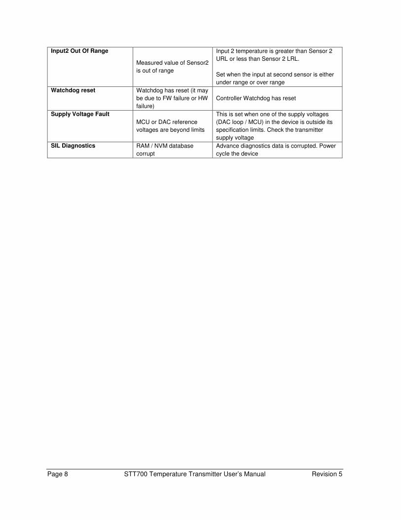
Page 8 STT700 Temperature Transmitter User’s Manual Revision 5
Input2 Out Of Range
Measured value of Sensor2
is out of range
Input 2 temperature is greater than Sensor 2
URL or less than Sensor 2 LRL.
Set when the input at second sensor is either
under range or over range
Watchdog reset Watchdog has reset (it may
be due to FW failure or HW
failure)
Controller Watchdog has reset
Supply Voltage Fault
MCU or DAC reference
voltages are beyond limits
This is set when one of the supply voltages
(DAC loop / MCU) in the device is outside its
specification limits. Check the transmitter
supply voltage
SIL Diagnostics RAM / NVM database
corrupt
Advance diagnostics data is corrupted. Power
cycle the device

Revision 5 STT700 Temperature Transmitter User’s Manual Page 9
3. Installation and Startup
Installation Site Evaluation Evaluate the site selected for the STT700 SmartLine transmitter installation with respect to the
process system design specifications and Honeywell’s published performance characteristics for your
particular model and sensor selection. Some parameters that you may want to include in your site
evaluation are:
• Environmental Conditions:
o Ambient temperature
o Relative humidity
• Potential Noise Sources:
o Radio frequency interference (RFI)
o Electromagnetic interference (EMI)
• Vibration Sources
o Pumps
o Motorized system devices (e.g., pumps)
o Valve cavitation
• Process Parameters
o Temperature
o Maximum sensor input ratings
Honeywell MC Toolkit In preparation for post-installation processes, refer to the MC Toolkit User Manual (MCT404),
Document # 34-ST-25-50, for device operation and maintenance information.
Page 10 STT700 Temperature Transmitter User’s Manual Revision 5
Mounting and Dimensions
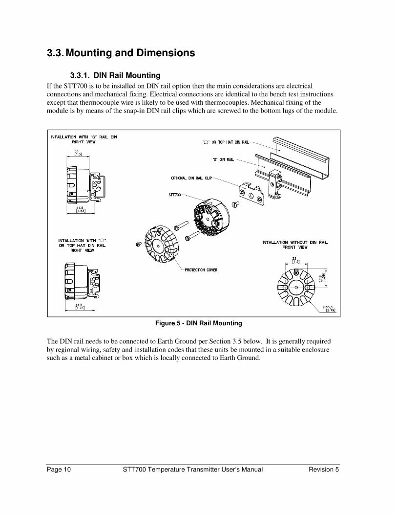
DIN Rail Mounting
If the STT700 is to be installed on DIN rail option then the main considerations are electrical
connections and mechanical fixing. Electrical connections are identical to the bench test instructions
except that thermocouple wire is likely to be used with thermocouples. Mechanical fixing of the
module is by means of the snap-in DIN rail clips which are screwed to the bottom lugs of the module.
Figure 5 - DIN Rail Mounting
The DIN rail needs to be connected to Earth Ground per Section 3.5 below. It is generally required
by regional wiring, safety and installation codes that these units be mounted in a suitable enclosure
such as a metal cabinet or box which is locally connected to Earth Ground.
Revision 5 STT700 Temperature Transmitter User’s Manual Page 11
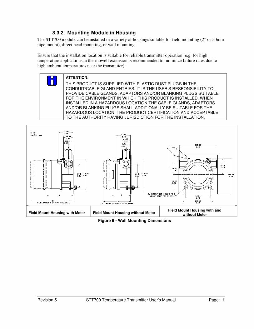
Mounting Module in Housing
The STT700 module can be installed in a variety of housings suitable for field mounting (2” or 50mm
pipe mount), direct head mounting, or wall mounting.
Ensure that the installation location is suitable for reliable transmitter operation (e.g. for high
temperature applications, a thermowell extension is recommended to minimize failure rates due to
high ambient temperatures near the transmitter).
ATTENTION:
THIS PRODUCT IS SUPPLIED WITH PLASTIC DUST PLUGS IN THE CONDUIT/CABLE GLAND ENTRIES. IT IS THE USER’S RESPONSIBILITY TO PROVIDE CABLE GLANDS, ADAPTORS AND/OR BLANKING PLUGS SUITABLE FOR THE ENVIRONMENT IN WHICH THIS PRODUCT IS INSTALLED. WHEN INSTALLED IN A HAZARDOUS LOCATION THE CABLE GLANDS, ADAPTORS AND/OR BLANKING PLUGS SHALL ADDITIONALLY BE SUITABLE FOR THE HAZARDOUS LOCATION, THE PRODUCT CERTIFICATION AND ACCEPTABLE TO THE AUTHORITY HAVING JURISDICTION FOR THE INSTALLATION.
Field Mount Housing with Meter Field Mount Housing without Meter Field Mount Housing with and
without Meter
Figure 6 - Wall Mounting Dimensions
Page 12 STT700 Temperature Transmitter User’s Manual Revision 5
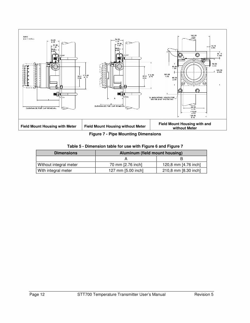
Field Mount Housing with Meter Field Mount Housing without Meter Field Mount Housing with and
without Meter
Figure 7 - Pipe Mounting Dimensions
Table 5 - Dimension table for use with Figure 6 and Figure 7
Dimensions Aluminum (field mount housing)
A B
Without integral meter 70 mm [2.76 inch] 120,8 mm [4.76 inch]
With integral meter 127 mm [5.00 inch] 210,8 mm [8.30 inch]
Revision 5 STT700 Temperature Transmitter User’s Manual Page 13
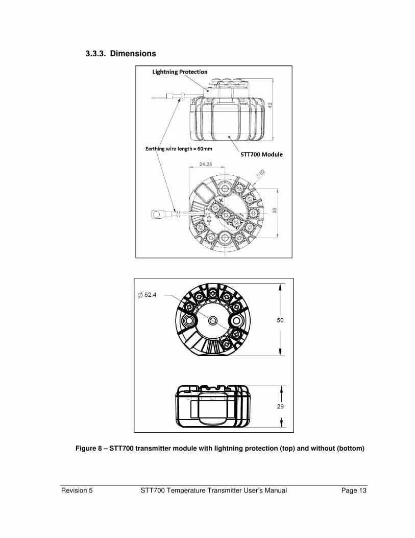
Dimensions
Figure 8 – STT700 transmitter module with lightning protection (top) and without (bottom)

Page 14 STT700 Temperature Transmitter User’s Manual Revision 5
3.3.3.1. Housing Cover and O Ring:
1. Review O-ring condition & replace, if damaged. New O-ring can be ordered
from spare parts list.
2. Apply O-ring lubricant to the end cap O-ring. Relax O-ring twists, if any.
3. Assemble housing cover with sufficient torque for securing against IP.
Figure 9: Housing cover and O-ring
Revision 5 STT700 Temperature Transmitter User’s Manual Page 15
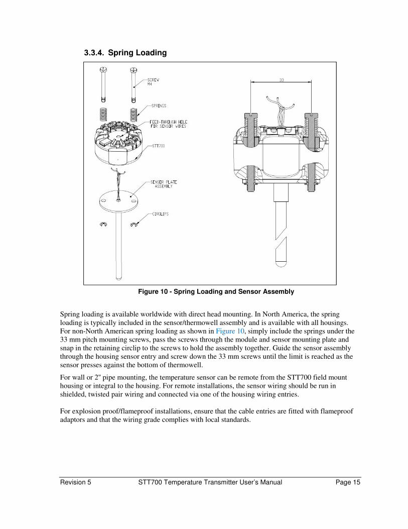
Spring Loading
Figure 10 - Spring Loading and Sensor Assembly
Spring loading is available worldwide with direct head mounting. In North America, the spring
loading is typically included in the sensor/thermowell assembly and is available with all housings.
For non-North American spring loading as shown in Figure 10, simply include the springs under the
33 mm pitch mounting screws, pass the screws through the module and sensor mounting plate and
snap in the retaining circlip to the screws to hold the assembly together. Guide the sensor assembly
through the housing sensor entry and screw down the 33 mm screws until the limit is reached as the
sensor presses against the bottom of thermowell.
For wall or 2'' pipe mounting, the temperature sensor can be remote from the STT700 field mount
housing or integral to the housing. For remote installations, the sensor wiring should be run in
shielded, twisted pair wiring and connected via one of the housing wiring entries.
For explosion proof/flameproof installations, ensure that the cable entries are fitted with flameproof
adaptors and that the wiring grade complies with local standards.

Page 16 STT700 Temperature Transmitter User’s Manual Revision 5
Installation Procedure of Standard display for STT700: Including removing brackets, housing, connection and wiring details
Tools required
For this item Use this tool
M3 set screw for end cap removal 1.5 mm Allen key
Transmitter re-assembly Parker Super O-ring lubricant or equivalent
Field upgrades Pliers
Uninstalling/Installing Standard Display for external wiring
Step – 1: When installed as explosion-proof or flame-proof in a hazardous location, keep covers
tight while the transmitter is energized. Disconnect power to the transmitter in the non-hazardous area
prior to removing end caps for service.
When installed as non-incendive or non-sparking equipment in a hazardous location, disconnect
power to the transmitter in the non-hazardous area, or determine that the location is non-hazardous
before disconnecting or connecting the transmitter wires.
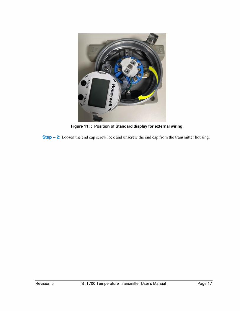
Unscrew 4-6 threads of the display bracket on both the sides. Hold the bracket at the right-hand side
(open hole side) and rotate in clock wise direction as shown in
Figure 11.
Revision 5 STT700 Temperature Transmitter User’s Manual Page 17
Figure 11: : Position of Standard display for external wiring
Step – 2: Loosen the end cap screw lock and unscrew the end cap from the transmitter housing.

Page 18 STT700 Temperature Transmitter User’s Manual Revision 5
Cable connection between Standard Display & STT Module:
Step – 3: Complete the cable connections between the standard display and STT module as follows.
a) Orient & Assemble the standard display module onto the bracket as shown in
b) Figure 12. Align the display module with the slots in the bracket and push. Check if
the module is fitted properly into the bracket and is tight.
Figure 12: Assembly of Standard display with Bracket
c) Connect the shorter cable connector to the display module at the indicated location.
Ensure that the first pin of the cable connector (indicated with the black colored wire)
matches with the first pin of the display connector (indicated with white spot). Refer
Figure 13.
Figure 13: short cable and display assembly
Black wire indication
first pin location
Revision 5 STT700 Temperature Transmitter User’s Manual Page 19
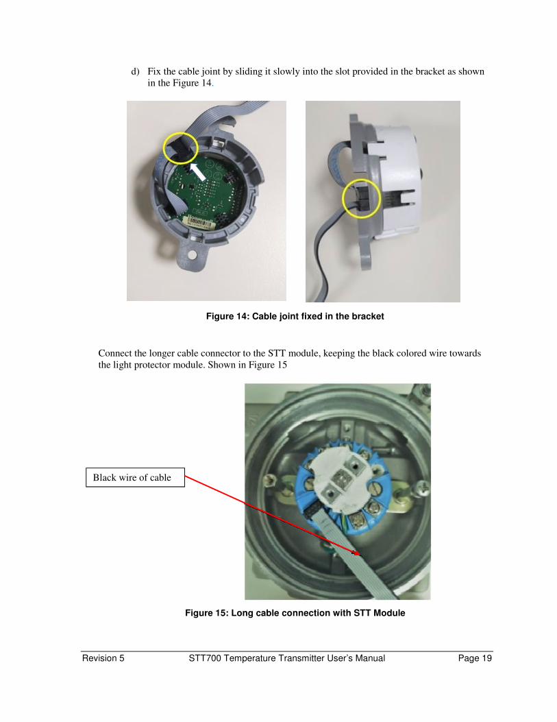
d) Fix the cable joint by sliding it slowly into the slot provided in the bracket as shown
in the Figure 14.
Figure 14: Cable joint fixed in the bracket
Connect the longer cable connector to the STT module, keeping the black colored wire towards
the light protector module. Shown in Figure 15
Figure 15: Long cable connection with STT Module
Black wire of cable
Page 20 STT700 Temperature Transmitter User’s Manual Revision 5
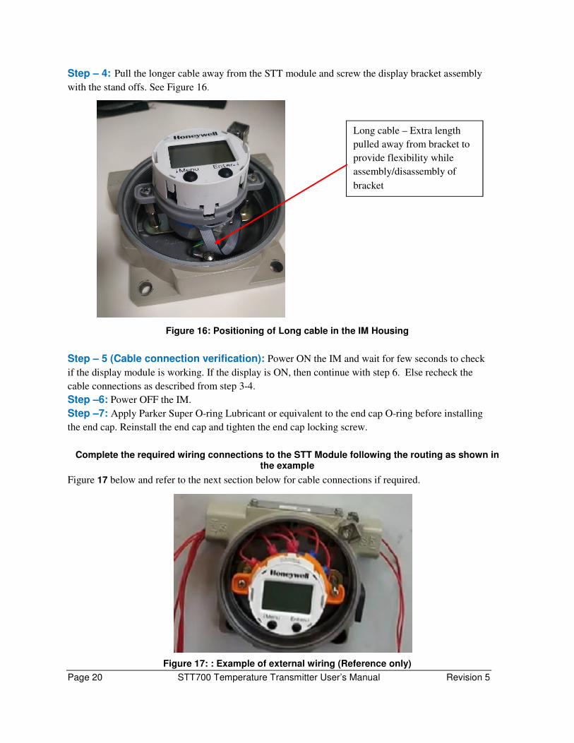
Step – 4: Pull the longer cable away from the STT module and screw the display bracket assembly
with the stand offs. See Figure 16.
Figure 16: Positioning of Long cable in the IM Housing
Step – 5 (Cable connection verification): Power ON the IM and wait for few seconds to check
if the display module is working. If the display is ON, then continue with step 6. Else recheck the
cable connections as described from step 3-4.
Step –6: Power OFF the IM.
Step –7: Apply Parker Super O-ring Lubricant or equivalent to the end cap O-ring before installing
the end cap. Reinstall the end cap and tighten the end cap locking screw.
Complete the required wiring connections to the STT Module following the routing as shown in the example
Figure 17 below and refer to the next section below for cable connections if required.
Figure 17: : Example of external wiring (Reference only)
Long cable – Extra length
pulled away from bracket to
provide flexibility while
assembly/disassembly of
bracket

Revision 5 STT700 Temperature Transmitter User’s Manual Page 21

Page 22 STT700 Temperature Transmitter User’s Manual Revision 5
Wiring a transmitter Please note the display module must be removed from support bracket to access the power
connections for HART or DE.
Loop Power Overview
The transmitter is designed to operate in a two-wire power/current loop with loop resistance and
power supply voltage within the HART or DE operating range shown in Figure 18 and Figure 19.
Figure 18 – STT700 with HART Transmitter Operating Ranges
Figure 19– STT700 with DE Transmitter Operating Ranges

Revision 5 STT700 Temperature Transmitter User’s Manual Page 23
Loop wiring is connected to the transmitter by simply attaching the positive (+) and negative (–) loop
wires to the positive (+) and negative (–) terminals on the transmitter module terminal block. Route
the wires through the pre-moded channels on top of the terminal module. Connect the loop power
wiring shield to Earth Ground only at the power supply end.
Note that the STT700 transmitter features SmartLine’s Universal terminal wiring capability and thus
is not polarity-sensitive.
With the single input HART transmitter, four (4) terminal screws will be available on the top of the
module. When either the dual-input HART or the single input DE is supplied, five (5) termination
screws will be included.
Figure 20 –STT700 module terminal connections
This transmitter uses the two mounting screws to connect it to Earth Ground. Grounding the
transmitter for proper operation is required, as doing so tends to minimize the possible effects of noise
on the output signal and affords protection against lightning and static discharge. An optional
lightning protection module is available for use in areas that are highly susceptible to lightning
strikes. As noted above, the loop power wiring shield should only be connected to Earth Ground at
the power supply end.
Wiring must comply with local codes, regulations and ordinances. The current output signal will operate a floating or ground system. If the signal appears noisy or erratic, it is recommended to ground the loop at the negative terminal of the power supply. Shielding should only be connected to ground at one point to avoid ground loops.
Page 24 STT700 Temperature Transmitter User’s Manual Revision 5
For HART and DE, the transmitter is designed to operate in a two-wire power/current loop with loop
resistance and power supply voltage within the operating range; see Figure 18 and Figure 19. With an
optional remote meter, the voltage drop for this must be added to the basic power supply voltage
requirements, to determine the required transmitter voltage (VXMTR) and maximum loop resistance
(RLOOP MAX). Additional consideration is required when selecting intrinsic safety barriers to ensure that
they will supply at least minimum transmitter voltage (VXMTR MIN), including the required 250 ohms of
resistance (typically within the barriers) needed for digital communications.
Transmitter loop parameters are as follows:
RLOOP MAX = maximum loop resistance (barriers plus wiring) that will allow proper transmitter
operation and is calculated as RLOOP MAX = (VSUPPLY MIN – VXMTR MIN - VSM) ÷÷÷÷ 21.8 mA.
In this calculation:
VXMTR MIN = 10.8 V
VSM = 2.3 V if using EU or Remote meter, 0V if not using EU or Remote meter
Note that VSM should only be considered if an EU meter will be connected to the transmitter.
The positive and negative loop wires are connected to the positive (+) and negative (–) terminals on
the STT700.
Barriers can be installed per Honeywell’s instructions for transmitters to be used in intrinsically safe
applications.
Note: Problems detected as non-critical diagnostics may affect performance without driving the
analog output to the programmed burnout level (for HART only). For DE, the burnout direction
needs to be selected in the hardware and this will be detected at power on time.
Digital System Integration Information
DE transmitters that are to be digitally integrated to Honeywell’s Total Plant Solution (TPS) system
will be connected to the temperature transmitter Interface Module in the Process Manager, Advanced
Process Manager or High Performance Process Manager through a Field Termination Assembly.
Details about the TPS system connections are given in the PM/APM SmartLine Transmitter
Integration Manual, PM12-410, which is part of the TDC 3000X system bookset.
When digitally integrating a transmitter in an Allen Bradley Programmable Logic Controller (PLC)
process system, the same Field Terminal Assembly (FTA) and wiring procedures used with
Honeywell’s TPS system are also used with the Allen-Bradley 1771 and 1746 platforms.
Wiring Variations
The above procedures are used to connect power to a transmitter. For loop wiring, sensor wiring and
external wiring, detailed drawings are provided for transmitter installation in non-intrinsically safe
areas and for intrinsically safe loops in hazardous area locations.
If you are using the transmitter with Honeywell’s TPS system, see PM/APM SmartLine Transmitter
Integration Manual, PM12-410, which is part of the TDC 3000X system bookset.

Revision 5 STT700 Temperature Transmitter User’s Manual Page 25
Grounding and Lightning Protection
Connect a wire from the mounting screws to Earth Ground to make the protection effective. Use size
14 AWG or 2.0mm2 bare or green covered wire for this connection.
For ungrounded thermocouple, mV, RTD or ohm inputs, connect the input wiring shield(s) to the
same Earth Ground connection.
For grounded thermocouple inputs, connect the internal ground connection shown in Figure 20 to the
same Earth Ground as used by the thermocouple. For direct head mount housings, the ground
terminal may not exist and another means of direct ground connection will need to be devised. For
proper protection, the green ground wire must be securely connected to a local ground in as direct a
path as possible. As noted above, the loop power wiring shield should only be connected to Earth
Ground at the power supply end.
The tightening torque to be applied on the wire termination screws are to be between 0.34 Nm (3 in-lbf) min to 0.56 Nm (5 in-lbf) max.
Shielded twisted pair cable gauge 18AWG-22AWG for the sensor connections and 22AWG – 14AWG for the loop power connections. The tightening torque to be applied on the STT700 module mounting screws are to be between 1.0 Nm (8.85 in-lbf) min to 1.35 Nm (12 in-lbf) max.
Input Sensor Wiring
3.5.5.1. Sensor Wiring Best Practice Recommendation:
• Sensor cable should be a shielded cable and the shield should be connected to protection earth
at the transmitter end. Refer Figure 20, STT700 module terminal connections for details of
grounding screw.
• Sensor lines should be isolated from high voltage lines and should not be routed in parallel
with high voltage lines.
• Sensor wires are designed to be routed through a controlled EMC environment. Possible
sources of surges shall be avoided.
• For any queries contact Honeywell Technical support team.
Page 26 STT700 Temperature Transmitter User’s Manual Revision 5
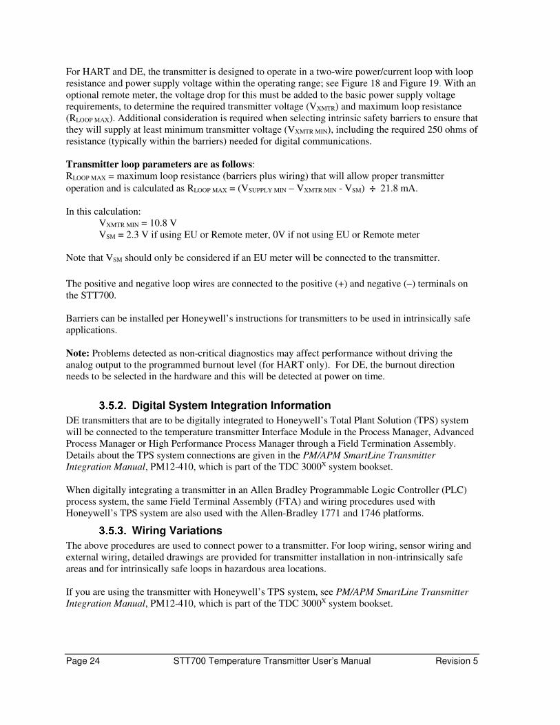
Connect the input sensors as shown in figures below for RTD, thermocouple, mV and ohm
connections.
Figure 21 – HART/DE Input Wiring Diagram for single sensor connection
The single sensor connections can also be used on a dual input transmitter when a second input is not
required. In this case, it is recommended that the second input be configured to None in the software.
In case of RTD type being configured for 4-wire, the configuration for single input is automatically
done.
Figure 22 – Wiring Diagram for HART Dual Sensor Connections

Revision 5 STT700 Temperature Transmitter User’s Manual Page 27
Lightning Protector
The lightning protection device is designed to give the STT700 temperature transmitter maximum
protection against surges such as those generated by lightning strikes. It mounts on the top of the
STT700 transmitter module, providing easy field wiring and also protection for the EU meter if used.
The compact mounting allows the use of a variety of housings including the Honeywell explosion
proof field mount housing.
The device can be used in both intrinsic safety and flame/explosion proof applications.
Figure 23 – STT700 with Lightning Protector Dimensions
Page 28 STT700 Temperature Transmitter User’s Manual Revision 5
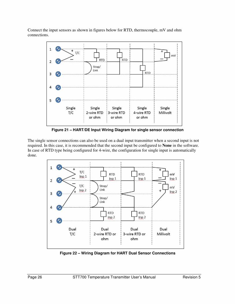
3.5.6.1. Installation
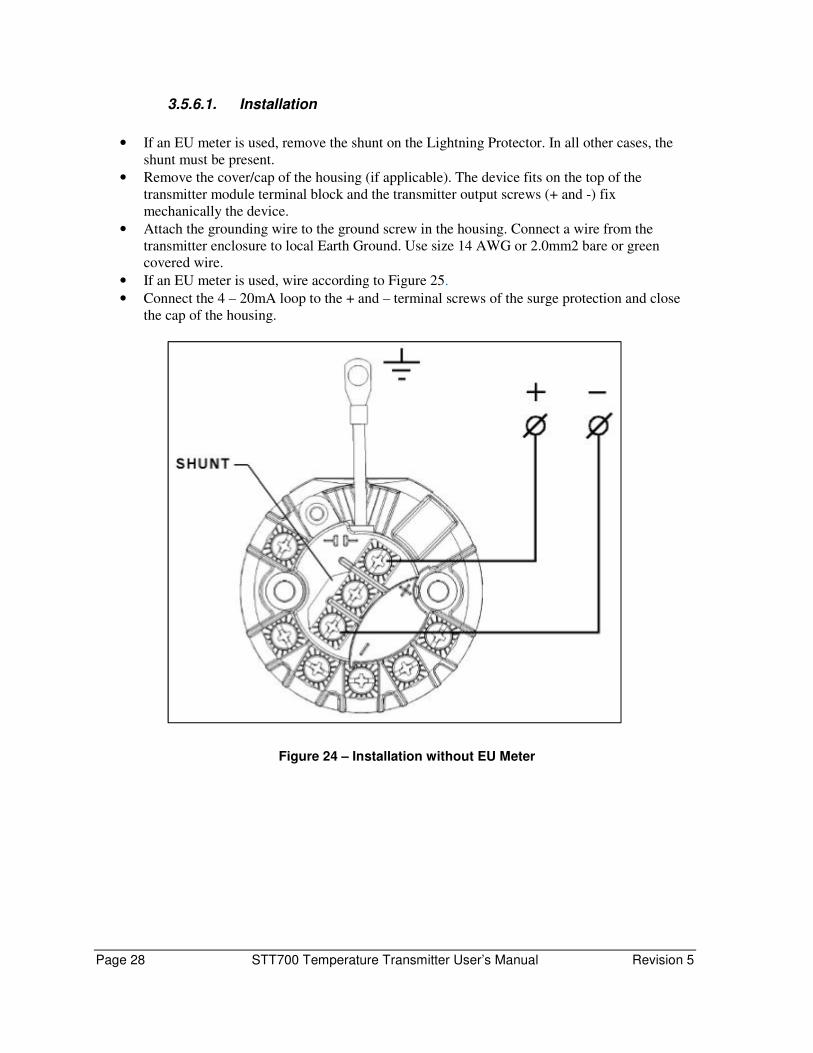
• If an EU meter is used, remove the shunt on the Lightning Protector. In all other cases, the
shunt must be present.
• Remove the cover/cap of the housing (if applicable). The device fits on the top of the
transmitter module terminal block and the transmitter output screws (+ and -) fix
mechanically the device.
• Attach the grounding wire to the ground screw in the housing. Connect a wire from the
transmitter enclosure to local Earth Ground. Use size 14 AWG or 2.0mm2 bare or green
covered wire.
• If an EU meter is used, wire according to Figure 25.
• Connect the 4 – 20mA loop to the + and – terminal screws of the surge protection and close
the cap of the housing.
Figure 24 – Installation without EU Meter
Revision 5 STT700 Temperature Transmitter User’s Manual Page 29
Figure 25 – Installation with EU Meter
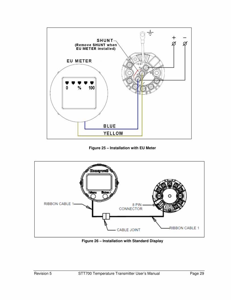
Figure 26 – Installation with Standard Display

Page 30 STT700 Temperature Transmitter User’s Manual Revision 5
3.5.6.2. Maintenance
The unit is designed to give a long service life under normal industrial conditions. However, if
exposed to a large number of high energy transients beyond the capability of the unit, the lightning
protector may fail. The unit has been designed so that, under excessive surge conditions (more than
10 KA), the lightning protector should fail, thus protecting the transmitter.
If the unit has failed, it can be replaced in the field – the process for removal in the reserve of that
for installing the unit.
If a replacement is not immediately available, part number 50133588-501-501, it is possible to
bypass the unit by wiring directly to the transmitter; however, it should be remembered that, in this
case, the transmitter will be unprotected from surges.

Revision 5 STT700 Temperature Transmitter User’s Manual Page 31
4. Startup Overview
This section identifies typical startup tasks the STT700 temperature transmitter and includes the
procedure for running an optional analog output check.
Startup Tasks
After completing the installation and configuration tasks for a transmitter, you are ready to startup the
process loop. Startup usually includes:
• Setting initial resistance, based on actual temperature (RTD sensor types only)
• Reading inputs and outputs
• Applying process inputs to the transmitter.
You can also run an optional output check to wring out an analog loop and check out individual
Process Variable (PV) outputs in Digitally Enhanced (DE) mode before startup.
The actual steps in a startup procedure vary based on the type of transmitter and the measurement
application. In general, the procedures in this section are based on using Honeywell MC Toolkit, with
a HART or DE variant, to check the transmitter input and output under static process conditions, and
make adjustments as required initiating full operation with the running process.
Output Check Procedures
The Output Check comprises the following procedures:
• The Loop Test procedure checks for continuity and the condition of components in the output
current loop.
• The Trim DAC Current procedure calibrates the output of the Digital-to-Analog converter for
minimum (0%) and maximum (100%) values of 4 mA and 20 mA, respectively. This
procedure is used for transmitters operating online in analog mode to ensure proper operation
with associated circuit components (for example, wiring, power supply, control equipment).
Precision test equipment (an ammeter or a voltmeter in parallel with precision resistor) is
required for the Trim DAC Current procedure.
• The Apply Values procedure uses actual Process Variable (PV) input levels for calibrating
the range of a transmitter. The PV is carefully adjusted to stable minimum and maximum
levels, and the Lower Range Limit Value (LRV) and Upper Range Limit Value (URV) are
then set by commands from the MC Toolkit.
The transmitter does not measure the given PV input or update the PV output while it operates in the Output mode.
Page 32 STT700 Temperature Transmitter User’s Manual Revision 5
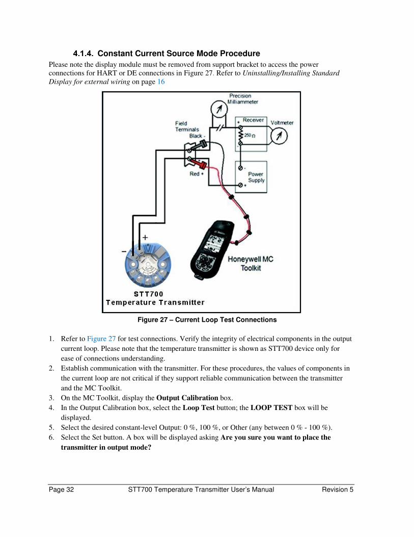
Constant Current Source Mode Procedure
Please note the display module must be removed from support bracket to access the power
connections for HART or DE connections in Figure 27. Refer to Uninstalling/Installing Standard
Display for external wiring on page 16
Figure 27 – Current Loop Test Connections
1. Refer to Figure 27 for test connections. Verify the integrity of electrical components in the output
current loop. Please note that the temperature transmitter is shown as STT700 device only for
ease of connections understanding.
2. Establish communication with the transmitter. For these procedures, the values of components in
the current loop are not critical if they support reliable communication between the transmitter
and the MC Toolkit.
3. On the MC Toolkit, display the Output Calibration box.
4. In the Output Calibration box, select the Loop Test button; the LOOP TEST box will be
displayed.
5. Select the desired constant-level Output: 0 %, 100 %, or Other (any between 0 % - 100 %).
6. Select the Set button. A box will be displayed asking Are you sure you want to place the
transmitter in output mode?

Revision 5 STT700 Temperature Transmitter User’s Manual Page 33
With the transmitter in Analog mode, you can observe the output on an
externally-connected meter or on a local meter.
7. Select the Yes button. Observe the output current at the percentage you selected in Step 5.
8. To view the monitor display, navigate back from the LOOP TEST display, and select the
MONITOR display. A Confirm popup will be displayed.
9. Select Yes to continue. This concludes the Startup procedure.
Page 34 STT700 Temperature Transmitter User’s Manual Revision 5
5. Operation
Overview The Operations section describes the internal operation of the STT700 transmitter and the operations
of the Smart Field Communicator and the HART communicator with the STT700. If an EU Meter is
installed, see the Engineering Unit Meter User Guide 34-ST-25-18 for additional information on
operations.
This transmitter is powered via the 2-wire, 4-20 mA signal connected to the + and - terminals on the
output side of the module.
Configuration Tools
Smart Field Communicator (SFC) for DE Models
As previously indicated, the SFC communicates by connecting across the 4-20 mA wiring. DE
communication is by 16 mA pulses which disturb the 4-20 mA output signal. When in analog mode,
ensure that receiving instruments are not on automatic control. The SFC does not feed 16 mA pulses
into the loop but instead merely uses the power on the 4-20 mA wires and switches it through a field
effect transistor output switch. The SFC always acts as a master and the transmitter as a slave. When
the transmitter is operating in the digital DE mode, there is no wake-up pulse required and the SFC
communication does not disturb the PV signal. Consequently, there is no need to put the loop on
manual control when operating in the DE mode.
Supported Commands:
• Read/write ID (e.g. TID 250)
• Select a sensor type (e.g. Pt100)
• Enable/disable sensor break detection
• Set damping time (e.g. 0 second)
• Set LRV and URV
• Read URL (upper range limit), LRL (lower range limit) and span
• Read process value and cold junction value in engineering units
• Read output in % of span
• Read software version
• Read fail-safe direction configured by link
• Set/reset user calibration to specific sensor
• Set 0 and 100% output calibration
• Force output current
• Read/write scratch pad
• Select broadcast type 4 or 6 bytes (Digital DE only). 6 bytes broadcasts PV and transmitter database while 4 bytes broadcasts PV only
• Enable/disable write protect
• Enable/disable latching. Latching means the alarm needs acknowledgment. Press "STATUS" key to acknowledge the alarm. If latching is disabled, the transmitter will leave the alarm mode as soon as the alarm cause disappears.

Revision 5 STT700 Temperature Transmitter User’s Manual Page 35
HART Communicator Model 375, 475 or MC Toolkit FDC for HART 7 Models
Connect the HART communicator by attaching the leads in parallel with the input (24V) terminals of
the device. HART communication consists of a high frequency carrier superimposed onto the 4-20
mA signal. The HART transmitter transmits by modulating the 4-20 mA DC loop current with a 1
mA peak to peak (p-p) AC current signal.
Supported Commands
• Read/write ID
• Select Dual Mode TC/TC, RTD/RTD
• Select sensor type
• Select PV/SV units
• Select damping time
• Set LRV and URV
• Read URL and LRL
• Read analog output
• Read Sensor1 and Sensor2
• Read % Output
• Read Process Value (PV)
• Read Cold Junction (CJ) Value
• Read fail-safe direction
• Set 0% and 100% output calibration
• Force output current
• Enable/disable latching
• XS Delta detection ON/OFF
• Set Delta Alarm
• Read Delta
• Match PVs
• Read device status
• Set/clear write protect
• Select Loop Control Mode – Average, Difference, Sensor1, Sensor2, Redundant and Split-
Range
• Lock/Unlock device
• Read/Write Long tag
• Read/write message, descriptor, date
• Read/Write polling address
• Read/Write loop current mode

Page 36 STT700 Temperature Transmitter User’s Manual Revision 5
Advanced Diagnostics
• Read Install Date
• Write Install Date
• Read Calibration Date and Time
• Write Correct LRV Date and Time
• Write Correct URV Date and Time
• Read Time in service value
• Read first set of Error log data
• Read second set of Error log data
• Read Error Log option status
• Write Error Log option status
• Reset Error Log
• Read PV tracking data
• Read SV tracking data
• Write high and low alarm limits for PV and SV
• Reset tracking data
• Read power up count
• Reset power up count value
• Read device model number
• Read Sensor1 and Sensor2 limits
• Read middle range value (MRV)
• Write middle range value (MRV)
• Read Loop Control option value
• Write Loop Control option value
• Read hysteresis
• Write hysteresis value
• Read damping value for bump less transfer (applicable to Split Range option)
• Write damping value for bump less transfer (applicable to Split Range option)
Revision 5 STT700 Temperature Transmitter User’s Manual Page 37
6. Maintenance
Overview Maintenance of this transmitter is limited to ensuring that connections, seals and mounting hardware
are tight and secure. There are no moving parts or adjustments, thus, the only reason to open the
housing (where supplied) is to inspect for corrosion or conductive dust entry which could later affect
reliable operation.
WARNING: The transmitter module itself should NEVER be opened.
Preventive Maintenance Practices and Schedules This SmartLine transmitter does not require any specific maintenance at regularly scheduled intervals.
Please take appropriate steps to avoid ESD damage when handling
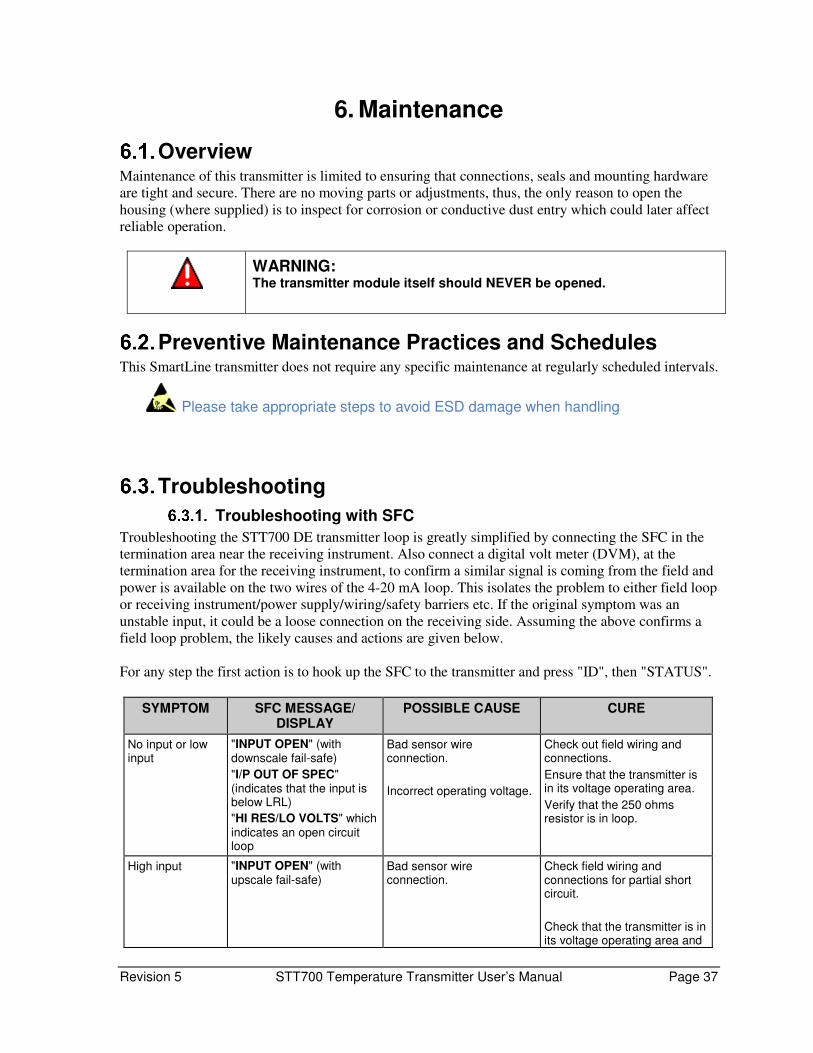
Troubleshooting
Troubleshooting with SFC
Troubleshooting the STT700 DE transmitter loop is greatly simplified by connecting the SFC in the
termination area near the receiving instrument. Also connect a digital volt meter (DVM), at the
termination area for the receiving instrument, to confirm a similar signal is coming from the field and
power is available on the two wires of the 4-20 mA loop. This isolates the problem to either field loop
or receiving instrument/power supply/wiring/safety barriers etc. If the original symptom was an
unstable input, it could be a loose connection on the receiving side. Assuming the above confirms a
field loop problem, the likely causes and actions are given below.
For any step the first action is to hook up the SFC to the transmitter and press "ID", then "STATUS".
SYMPTOM SFC MESSAGE/ DISPLAY
POSSIBLE CAUSE CURE
No input or low input
"INPUT OPEN" (with downscale fail-safe)
"I/P OUT OF SPEC" (indicates that the input is below LRL)
"HI RES/LO VOLTS" which indicates an open circuit loop
Bad sensor wire connection.
Incorrect operating voltage.
Check out field wiring and connections.
Ensure that the transmitter is in its voltage operating area.
Verify that the 250 ohms resistor is in loop.
High input "INPUT OPEN" (with upscale fail-safe)
Bad sensor wire connection.
Check field wiring and connections for partial short circuit.
Check that the transmitter is in its voltage operating area and

Page 38 STT700 Temperature Transmitter User’s Manual Revision 5
SYMPTOM SFC MESSAGE/ DISPLAY
POSSIBLE CAUSE CURE
"I/P OUT OF SPEC" (indicates that the input is above URL or below LRL)
Incorrect operating voltage. line resistance is not excessive.
Unstable onscale input
"STATUS CHECK = O.K." since any identified problem would give upscale or downscale fail-safe.
Bad sensor wire connection.
Intermittent open circuit of sensor.
Wiring disturbed by strong electromagnetic interference.
Check connection and wiring for intermittent connections.
Check that sensor fault detection is "ON", this allows detection of a bad sensor.
Protect wiring by using appropriate grounding, shielding etc.
Fail-safe output signal
"CRITICAL STATUS" A fail-safe output signal (critical status) can be caused by several reasons.
The SFC will indicate the source of the problem by displaying the appropriate error message.
Incorrect output signal with simulating device
"STATUS CHECK = O.K." but does not correspond to value set by simulating device
The most common error is changing the sensor wiring after probe type selection or after power-up.
Check the appropriate sensor wiring and power cycle when it is correct.
Remember when changing configuration to first connect sensor wiring correctly, then change configuration.
"INVALID REQUEST" when changing LRV or URV
"INVALID REQUEST" If the LRV is changed, the URV tries to change by the same amount to maintain the same SPAN. If this new URV exceeds the URL then this message appears.
Reduce the URV or SPAN before changing the LRV.
Non-critical status message, without # sign
"USER CORR ACTIVE" Transmitter has been trimmed for particular sensor range. This can be done by keying in LRV/URV, CORRECT, ENTER with exact LRV and URV input values to enable improved accuracy over the specifications.
When performing a Reset Correct command or a sensor type change, the transmitter will lose this sensor correction and fall back to the original factory calibration.
Remember that successful communications with the transmitter result in many useful pieces of data. With the initial I.D. response, the user can confirm that the:
1. Transmitter is powered
2. Line resistance is correct
Wires run to the correct unit. If not, the unit connected can be identified by the tag number.

Revision 5 STT700 Temperature Transmitter User’s Manual Page 39
Troubleshooting with HART communicator
Troubleshooting the STT700 HART transmitter loop is greatly simplified by connecting a HART
Communicator in the termination area near the receiving instrument. Also connect a digital volt
meter (DVM), at the termination area for the receiving instrument, to confirm a similar signal is
coming from the field and power is available on the two wires of the 4-20 mA loop. This isolates
the problem to either field loop or receiving instrument/power supply/wiring/safety barriers etc. If
the original symptom was an unstable input, it could be a loose connection on the receiving side.
Assuming the above confirms a field loop problem, the likely causes/actions are given below.
Condition Analysis Recommended Corrective Action
Diagnostics Failure.
A critical failure has been
detected on the HART Electronics.
Use a HART device
communicator to read the detailed status information from
the transmitter. Refer to the appropriate manual for more
details about the possible failure causes.
Power cycle the transmitter and if problem
persists replace the transmitter.
DAC Failure.
A critical failure has been detected on the HART
Electronics.
Use a HART device communicator to read the
detailed status information from the transmitter. Refer to the
appropriate manual for more details about the possible failure
causes.
Power cycle the transmitter and if problem persists replace the transmitter.
Sensor Input Failure.
A critical failure has been detected on the HART
Sensor Inputs.
Use a HART device communicator to read the detailed status information from
the transmitter. Refer to the
appropriate manual for more details about the possible failure
causes.
If detail status indicate input fault (open, short...), correct the root error by checking the input connection to the transmitter and
sensor type configuration.
If problem persists even after verifying the
input connection and sensor input type
configuration, replace the transmitter.
Configuration Corrupt.
A critical failure has been detected on the HART
Electronics.
Use a HART device communicator to read the
detailed status information from the transmitter. Refer to the
appropriate manual for more details about the possible failure
causes.
Power cycle the transmitter and if problem persists replace the transmitter.
For DE please refer to STT700 HART/DE option manual, #34-TT-25-18.

Page 40 STT700 Temperature Transmitter User’s Manual Revision 5
Recommended Parts
GENERAL DESCRIPTION: Reference
STT700 transmitter module device Order from the Model
Selection Guide to include
options as required.
METERS
Replacement EU meter 51451985-501
Meter mounting bracket kit 46188056-502
HEAD MOUNT HOUSINGS (Cable/Conduit entry noted. All have
½” NPT sensor entry)
Aluminum head mount housing (M20) 46188452-501
Aluminum head mount housing (1/2"NPT) 46188452-502
Flame proof cast iron head mount housing (M20) 46188453-501
Flame proof cast iron head mount housing (1/2"NPT) 46188453-502
FIELD MOUNT HOUSINGS (All have ½” NPT sensor and
cable/conduit entries)
Field mount housing - Aluminum beige epoxy-polyester hybrid painted 46188472-501
Field mount housing end cap - Aluminum beige epoxy 30752006-501
Field mount housing meter cap - Aluminum beige epoxy-polyester hybrid
painted
30755956-501
Field mount housing - Aluminum beige epoxy painted 46188472-502
Field mount housing end cap - Aluminum beige epoxy painted 46188471-501
Field mount housing meter cap - Aluminum beige epoxy painted 46188471-502
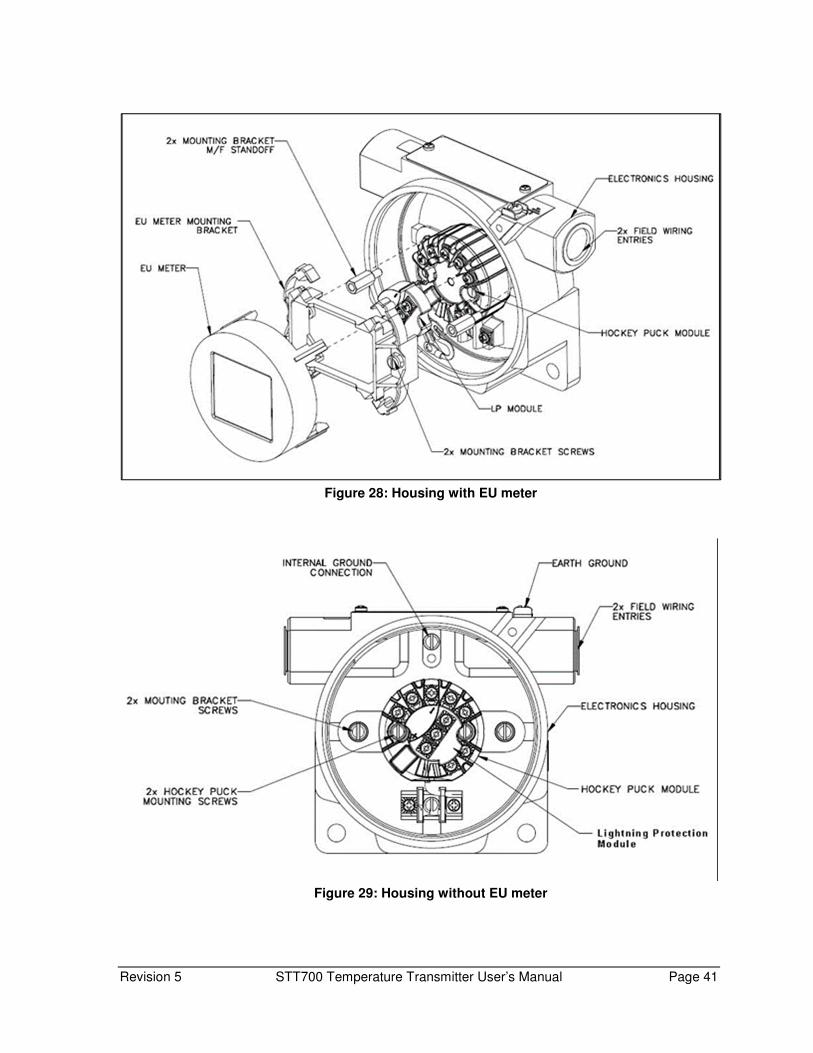
Revision 5 STT700 Temperature Transmitter User’s Manual Page 41
Figure 28: Housing with EU meter
Figure 29: Housing without EU meter

Page 42 STT700 Temperature Transmitter User’s Manual Revision 5
Figure 30: HOUSING WITH STANDARD DISPLAY
Figure 31: HOUSING WITHOUT STANDARD DISPLAY

Revision 5 STT700 Temperature Transmitter User’s Manual Page 43
MISCELLANEOUS PARTS (TBC)
Adaptor plate to install module in field mount housing 46188423-501
Spring loading mounting set 46188416-501
DIN rail mounting (top hat/"Ω" or "G" rail) 51156364-501
Carbon steel mounting bracket for 2" pipe
(for use with field mount housing)
30755905-501
Stainless steel mounting bracket for 2" pipe
(for use with field mount Housing)
30671907-501
1/2"NPT to M20 x 1.5 conduit adaptor (flameproof EEx d) 46188203-501
46188203-501
1/2"NPT Male to 3/4"NPT Female conduit adaptor 51196567-501
51196567-501
Transient protector (external to housing) 30755970-501
Stainless steel wired-on customer ID tag 50080380-501
Lightning Protector 50133588-501
Wiring and Installation Drawings Spring loading and sensor assembly 51307912-001
Pipe mounting dimensions for field mounting housing 46188468-201
Wall mounting dimensions for field mounting housing 46188467-201
DIN rail mounting for the STT700 transmitter module 51156364-501
Page 44 STT700 Temperature Transmitter User’s Manual Revision 5
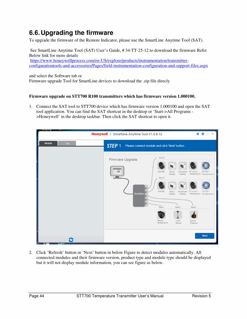
Upgrading the firmware To upgrade the firmware of the Remote Indicator, please use the SmartLine Anytime Tool (SAT).
See SmartLine Anytime Tool (SAT) User’s Guide, # 34-TT-25-12 to download the firmware Refer
Below link for more details
https://www.honeywellprocess.com/en-US/explore/products/instrumentation/transmitter-
configurationtools-and-accessories/Pages/field-instrumentation-configuration-and-support-files.aspx
and select the Software tab or
Firmware upgrade Tool for SmartLine devices to download the .zip file direcly
Firmware upgrade on STT700 R100 transmitters which has firmware version 1.000100.
1. Connect the SAT tool to STT700 device which has firmware version 1.000100 and open the SAT
tool application. You can find the SAT shortcut in the desktop or ‘Start->All Programs -
>Honeywell’ in the desktop taskbar. Then click the SAT shortcut to open it.
2. Click ‘Refresh’ button or ‘Next’ button in below Figure to detect modules automatically. All
connected modules and their firmware version, product type and module type should be displayed
but it will not display module information, you can see figure as below.

Revision 5 STT700 Temperature Transmitter User’s Manual Page 45
3. Double click on the empty module information. The “Firmware Upgrade” panel is displayed on
the right side of GUI as below

Page 46 STT700 Temperature Transmitter User’s Manual Revision 5
4. If your transmitter is HART module, then choose the module type as ‘HART
COMMUNICATION’ or if your transmitter is DE module then choose the module type as ‘DE
COMMUNICATION’.
5. Choose the correct firmware file from the dropdown list at right side of the GUI or click “+”
button to choose the firmware file from a PC file folder where the firmware files are stored.
Choose 50129929-701_R2.000000.hex for HART modules and choose 50129929-
702_R2.000000.hex for DE module.
6. User can download firmware by clicking the “Apply” button, as shown in the following:

Revision 5 STT700 Temperature Transmitter User’s Manual Page 47
7. The firmware will start downloading as below.
Page 48 STT700 Temperature Transmitter User’s Manual Revision 5
7. Calibration
Recommendations for transmitter Calibration The STT700 SmartLine Temperature Transmitter does not require periodic calibration to maintain
accuracy. Typically, calibration of a process-connected transmitter will degrade, rather than augment
the capability of a smart transmitter. For this reason, it is recommended that a transmitter be removed
from service before calibration. Moreover, calibration must be accomplished in a controlled,
laboratory-type environment, using certified precision equipment.
Calibration Procedures For a transmitter operating in analog mode, you must calibrate its output signal measurement range
using any compatible hand-held communicator..
One calibration option is to use the Honeywell MC Toolkit (MCT). Refer to the MC Toolkit User
Manual, MCT404, Document # 34-ST-25-50
Calibration information and procedures for a transmitter operating in the HART/DE mode are
provided in the STT700 Series HART/DE Option User’s manual, document number 34-TT-25-18,
Section on “Calibration.”
Revision 5 STT700 Temperature Transmitter User’s Manual Page 49
Appendix A. PRODUCT CERTIFICATIONS
A1. Safety Instrumented Systems (SIS) Installations For Safety Certified Installations, please refer to STT700 Safety Manual 34-TT-25-05 for installation
procedure and system requirements.
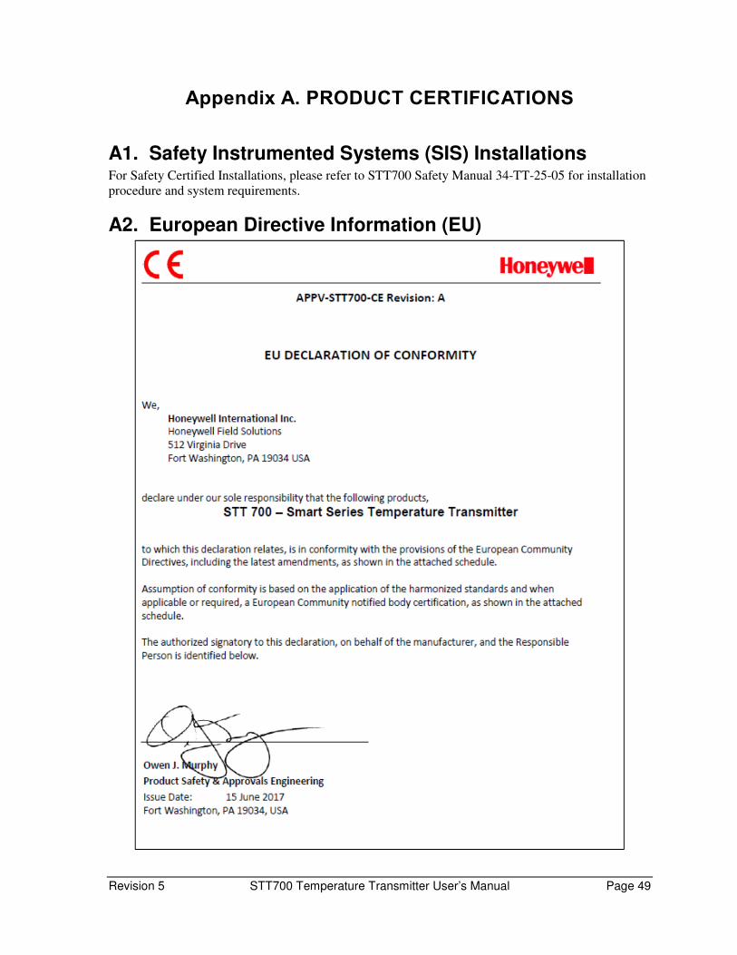
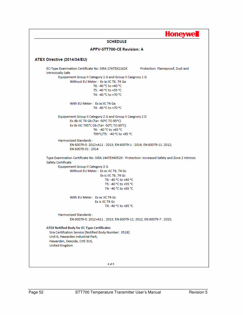
A2. European Directive Information (EU)

Page 50 STT700 Temperature Transmitter User’s Manual Revision 5
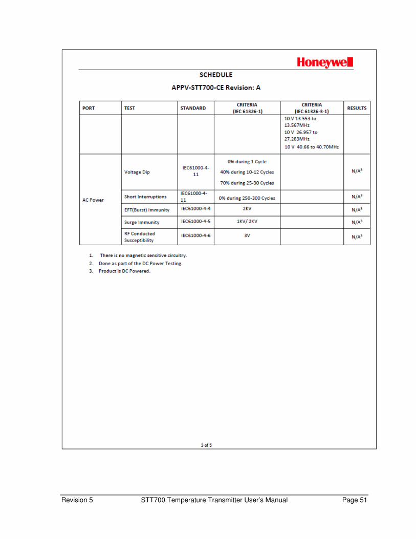
Revision 5 STT700 Temperature Transmitter User’s Manual Page 51
Page 52 STT700 Temperature Transmitter User’s Manual Revision 5

Revision 5 STT700 Temperature Transmitter User’s Manual Page 53

Page 54 STT700 Temperature Transmitter User’s Manual Revision 5
A3. China RoHS China RoHS compliance information is located here: (Pending)
https://www.honeywellprocess.com/library/support/Public/Documents/50136434.pdf
A4. Hazardous Locations Certifications
AGENCY MSG Code
TYPE OF PROTECTION Electrical
Parameters Ambient Temperature
FM ApprovalsTM
(USA)
F1
Intrinsically Safe Certificate: FM17US0112X Class I, Division 1, Groups A, B, C, D; T6.. T4 Class I Zone 0 AEx ia IIC T6.. T4 Ga
Note 2 T6: -40oC to +40oC T5: -40oC to +55oC T4: -40oC to +70oC
Non-Incendive and Zone 2 Intrinsically Safe Certificate: FM17US0112X Class I, Division 2, Groups A, B, C, D; T6..T4 Class I Zone 2 AEx nA IIC T6..T4 Gc Class I Zone 2 AEx ic IIC T6..T4 Gc
Note 1 Note 2 for “ic”
T6: -40oC to +40oC T5: -40oC to +55oC T4: -40oC to +85oC
F2
Intrinsically Safe Certificate: FM17US0112X Class I, Division 1, Groups A, B, C, D; Class II, Division 1, Groups E, F, G; Class III, Division 1: T6..T4 Class I Zone 0 AEx ia IIC T6.. T4 Ga
Note 2 T6: -40oC to +40oC T5: -40oC to +55oC T4: -40oC to +70oC
Explosion proof Certificate: FM17US0112X Class I, Division 1, Groups A, B, C, D; T6..T5 Class 1, Zone 1, AEx db IIC T6..T5 Gb Dust-Ignition proof Class II, Division 1, Groups E, F ,G; T5 Zone 21, AEx tb IIIC T95oC Db
Note 1 T6: -40oC to +65oC T5: -40oC to +85oC
Non-Incendive and Zone 2 Intrinsically Safe Certificate: FM17US0112X Class I, Division 2, Groups A, B, C, D; T6..T4 Class I Zone 2 AEx nA IIC T6.. T4 Gc Class I Zone 2 AEx ic IIC T6.. T4 Gc
Note 1 T6: -40oC to +40oC T5: -40oC to +55oC T4: -40oC to +85oC
Enclosure TYPE 4X/ IP66
Standards : FM 3600: 2018; ANSI/ UL 60079-0: 2013 FM 3615 : 2018; ANSI/ UL 60079-1: 2015 ; FM 3610: 2018; ANSI/ UL 60079-11 : 2014 FM 3810 : 2018 ; FM 3611:2018; ANSI/ UL 60079-15 : 2013
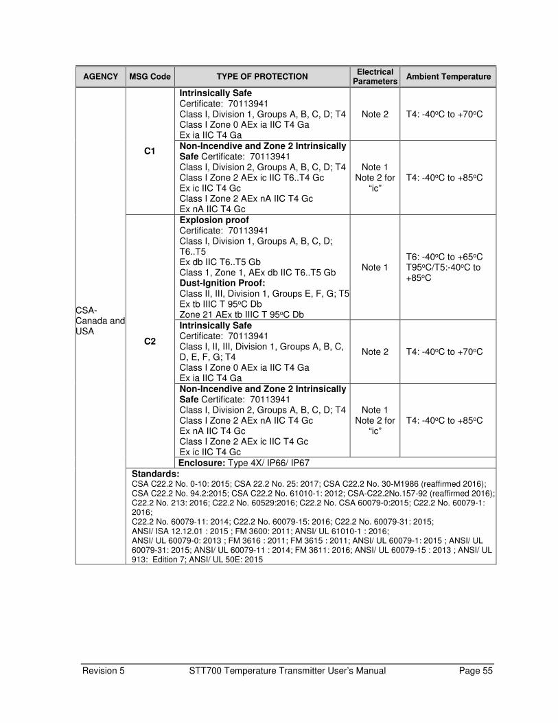
Revision 5 STT700 Temperature Transmitter User’s Manual Page 55
AGENCY MSG Code TYPE OF PROTECTION Electrical
Parameters Ambient Temperature
CSA- Canada and USA
C1
Intrinsically Safe Certificate: 70113941 Class I, Division 1, Groups A, B, C, D; T4 Class I Zone 0 AEx ia IIC T4 Ga Ex ia IIC T4 Ga
Note 2 T4: -40oC to +70oC
Non-Incendive and Zone 2 Intrinsically Safe Certificate: 70113941 Class I, Division 2, Groups A, B, C, D; T4 Class I Zone 2 AEx ic IIC T6..T4 Gc Ex ic IIC T4 Gc Class I Zone 2 AEx nA IIC T4 Gc Ex nA IIC T4 Gc
Note 1 Note 2 for
“ic” T4: -40oC to +85oC
C2
Explosion proof Certificate: 70113941 Class I, Division 1, Groups A, B, C, D; T6..T5 Ex db IIC T6..T5 Gb Class 1, Zone 1, AEx db IIC T6..T5 Gb Dust-Ignition Proof: Class II, III, Division 1, Groups E, F, G; T5 Ex tb IIIC T 95oC Db Zone 21 AEx tb IIIC T 95oC Db
Note 1 T6: -40oC to +65oC T95oC/T5:-40oC to +85oC
Intrinsically Safe Certificate: 70113941 Class I, II, III, Division 1, Groups A, B, C, D, E, F, G; T4 Class I Zone 0 AEx ia IIC T4 Ga Ex ia IIC T4 Ga
Note 2 T4: -40oC to +70oC
Non-Incendive and Zone 2 Intrinsically Safe Certificate: 70113941 Class I, Division 2, Groups A, B, C, D; T4 Class I Zone 2 AEx nA IIC T4 Gc Ex nA IIC T4 Gc Class I Zone 2 AEx ic IIC T4 Gc Ex ic IIC T4 Gc
Note 1 Note 2 for
“ic” T4: -40oC to +85oC
Enclosure: Type 4X/ IP66/ IP67
Standards: CSA C22.2 No. 0-10: 2015; CSA 22.2 No. 25: 2017; CSA C22.2 No. 30-M1986 (reaffirmed 2016); CSA C22.2 No. 94.2:2015; CSA C22.2 No. 61010-1: 2012; CSA-C22.2No.157-92 (reaffirmed 2016); C22.2 No. 213: 2016; C22.2 No. 60529:2016; C22.2 No. CSA 60079-0:2015; C22.2 No. 60079-1: 2016; C22.2 No. 60079-11: 2014; C22.2 No. 60079-15: 2016; C22.2 No. 60079-31: 2015; ANSI/ ISA 12.12.01 : 2015 ; FM 3600: 2011; ANSI/ UL 61010-1 : 2016; ANSI/ UL 60079-0: 2013 ; FM 3616 : 2011; FM 3615 : 2011; ANSI/ UL 60079-1: 2015 ; ANSI/ UL 60079-31: 2015; ANSI/ UL 60079-11 : 2014; FM 3611: 2016; ANSI/ UL 60079-15 : 2013 ; ANSI/ UL 913: Edition 7; ANSI/ UL 50E: 2015

Page 56 STT700 Temperature Transmitter User’s Manual Revision 5
AGENCY MSG Code TYPE OF PROTECTION Electrical
Parameters Ambient Temperature
ATEX
A1
Intrinsically Safe Certificate: SIRA 17ATE2162X II 1 G Ex ia IIC T4 Ga
Note 2 T4: -40oC to +70oC
Non Sparking and Zone 2 Intrinsically Safe Certificate: SIRA 17ATE4161X
II 3 G Ex ec IIC T4 Gc II 3 G Ex ic IIC T4 Gc
Note 1 Note 2 for
“ic” T4: -40oC to +70oC
A2
Flameproof Certificate: SIRA 17ATE2162X II 2 G Ex db IIC T6..T5 Gb II 2 D Ex tb IIIC T 95oC Db
Note 1
T6: -40oC to +65oC T95oC/T5:-40oC to
+85oC
Intrinsically Safe Certificate: SIRA 17ATE2162X
II 1 G Ex ia IIC T4 Ga
Note 2
T4: -40oC to +70oC
Category 3 Increased Safety and Intrinsically Safe Certificate: SIRA 17ATE4161X
II 3 G Ex ec IIC T4 Gc II 3 G Ex ic IIC T4 Gc
Note 1 Note 2 for
“ic” T4: -40oC to +85oC
Enclosure: IP66/ IP67
Standards : EN 60079-0: 2012+A11 : 2013; EN 60079-1 : 2014 ; EN 60079-11: 2012 ; EN 60079-7 : 2015 ; EN 60079-31 : 2014
IECEx
E1
Intrinsically Safe Certificate: SIR 17.0035X Ex ia IIC T4 Ga
Note 2 T4: -40oC to +70oC
Non Sparking, Zone 2 Intrinsically Safe Certificate: SIR 17.0035X Ex ec IIC T4 Gc Ex ic IIC T4 Gc
Note 1 Note 2 for
“ic” T4: -40oC to +85oC
E2
Flameproof Certificate: SIR 17.0035X Ex db IIC T6..T5 Gb Ex tb IIIC T 95oC Db
Note 1 T6: -40oC to +65oC T95oC/T5: -40oC to
+85oC
Intrinsically Safe Certificate: SIR 17.0035X Ex ia IIC T4 Ga
Note 2 T4: -40oC to +70oC
Zone 2- Increased Safety and Intrinsically Safe Certificate: SIR 17.0035X Ex ec IIC T4 Gc Ex ic IIC T4 Gc
Note 2 T4: -40oC to +85oC
Enclosure: IP66/ IP67
Standards: IEC 60079-0: 2011; IEC 60079-1 : 2014; IEC 60079-11 : 2011; IEC 60079-31 : 2014; IEC 60079-7 : 2015

Revision 5 STT700 Temperature Transmitter User’s Manual Page 57
AGENCY MSG Code
TYPE OF PROTECTION Electrical
ParametersAmbient Temperature
CCoE INDIA
P1 Intrinsically Safe Certificate: P417399/1 Ex ia IIC T4 Ga
Note 2 T4: -40oC to +70oC
P2
Flameproof Certificate: P417399/1 Ex db IIC T6..T5 Gb
Note 1 T6: -40oC to +65oC T5: -40oC to +85oC
Intrinsically Safe Certificate: P417399/1 Ex ia IIC T4 Ga
Note 2 T4: -40oC to +70oC
Enclosure: IP66/ IP67
NEPSI (China)
N1
Intrinsically Safe Certificate: GYJ18.1420X Ex ia IIC T4 Ga
Note 2 T4: -40oC to +70oC
Non Sparking, Zone 2 Intrinsically Safe Certificate: GYJ18.1420X Ex ec IIC T4 Gc Ex ic IIC T4 Gc
Note 1 Note 2 for
“ic” T4: -40oC to +85oC
N2
Flameproof Certificate: GYJ18.1420X Ex db IIC T6..T5 Gb Ex tD A21 IP6X T80 oC/ T95oC
Note 1 T6: -40oC to +65oC T95oC/T5: -40oC to
+85oC
Intrinsically Safe Certificate: GYJ18.1420X Ex ia IIC T4 Ga
Note 2 T4: -40oC to +70oC
Zone 2 Intrinsically Safe Certificate: GYJ18.1420X Ex ic IIC T4 Gc
Note 2 T4: -40oC to +85oC
Enclosure: IP66/ IP67
SAEx South Africa
S1
Intrinsically Safe Certificate: XPL 18.0865X Ex ia IIC T4 Ga
Note 2 T4: -40oC to +70oC
Non Sparking, Zone 2 Intrinsically Safe Certificate: XPL 18.0865X Ex ec IIC T4 Gc Ex ic IIC T4 Gc
Note 1 Note 2 for
“ic” T4: -40oC to +85oC
S2
Flameproof Certificate: XPL 18.0865X Ex db IIC T6..T5 Gb Ex tb IIIC T 95oC Db
Note 1 T6: -40oC to +65oC T95oC/T5: -40oC to
+85oC
Intrinsically Safe Certificate: XPL 18.0865X Ex ia IIC T4 Ga
Note 2 T4: -40oC to +70oC
Zone 2 Intrinsically Safe Certificate: XPL 18.0865X Ex ic IIC T4 Gc
Note 2 T4: -40oC to +85oC
Enclosure: IP66/ IP67
Notes 1. Operating Parameters: 4-20 mA/HART (Loop Terminal) - Voltage= 10.58 to 35 V, Current = 4-20 mA Normal (3.8 – 21.5 mA Faults) 2. Intrinsically Safe Entity Parameters For details see Control Drawing

Page 58 STT700 Temperature Transmitter User’s Manual Revision 5
A5. Marking ATEX Directive
General:
The following information is provided as part of the labeling of the transmitter:
• Name and Address of the manufacturer
• Notified Body identification: DEKRA Quality B.V., Arnhem, the Netherlands
• For complete model number, see the Model Selection Guide for the particular model of
temperature transmitter.
• The serial number of the transmitter is located on the Housing data-plate. The first two
digits of the serial number identify the year (02) and the second two digits identify the week
of the year (23); for example, 0223xxxxxxxx indicates that the product was manufactured in
2002, in the 23rd week.
Apparatus Marked with Multiple Types of Protection
The user must determine the type of protection required for installation the equipment. The
user shall then check the box [5 ] adjacent to the type of protection used on the equipment
certification nameplate. Once a type of protection has been checked on the nameplate, the
equipment shall not then be reinstalled using any of the other certification types.
A.6 WARNINGS and Cautions:
Intrinsically Safe and Non-Incendive Equipment:
WARNING: SUBSTITUTION OF COMPONENTS MAY IMPAIR SUITABILITY FOR USE IN
HAZARDOUS LOCATIONS.
Explosion-Proof/ Flameproof:
WARNING: DO NOT OPEN WHEN AN EXPLOSIVE ATMOSPHERE MAY BE PRESENT
Non-Incendive Equipment:
WARNING: DO NOT OPEN WHEN AN EXPLOSIVE ATMOSPHERE MAYBE PRESENT
All Protective Measures:
WARNING: FOR CONNECTION IN AMBIENTS ABOVE 60oC USE WIRE RATED 105oC

Revision 5 STT700 Temperature Transmitter User’s Manual Page 59
A.6 Conditions of Use” for Ex Equipment”, Hazardous Location Equipment or “Schedule of Limitations”:
The installer shall provide transient over-voltage protection external to the equipment such
that the voltage at the supply terminal of the equipment does not exceed 140% of the
voltage rating of the equipment.
Intrinsically Safe: Must be installed per drawing 50133855
Division 2: This equipment is suitable for use in a Class I, Division 2, Groups A, B, C, D; T4 or
Non-Hazardous Locations Only.
Transmitter only selection:
For ATEX Category 3 or Zone 2 Locations, the Transmitter must be installed within an
enclosure with a minimum degree of protection of IP54 in accordance with:
For US Installations: in a tool-secured enclosure which meets the requirements of
ANSI/ISA 60079-0 and ANSI/ISA 60079-15 and the ultimate application.
For ATEX or IECEx: in a tool-secured enclosure which meets the requirements of
EN/ IEC 60079-0 and EN/ IEC 60079-7 and the ultimate application.
Transmitter in Enclosure Selections:
Consult the manufacturer for dimensional information on the flameproof joints for repair.
Painted surface of the STT700 may store electrostatic charge and become a source of
ignition in applications with a low relative humidity less than approximately30% relative
humidity where the painted surface is relatively free of surface contamination such as dirt,
dust or oil. Cleaning of the painted surface should only be done with a damp cloth.
The enclosure is manufactured from low copper aluminum alloy. In rare cases, ignition
sources due to impact and friction sparks could occur. This shall be considered during
Installation, particularly if equipment is installed a Zone 0 location.
If a charge-generating mechanism is present, the exposed metallic part on the enclosure is
capable of storing a level of electrostatic that could become Incendive for IIC gases.
Therefore, the user/ installer shall implement precautions to prevent the buildup of
electrostatic charge, e.g. earthing the metallic part. This is particularly important if
equipment is installed a Zone 0 location.
For Installation of the NPT Plug or Adapter follow instructions as outlined in 34-XY-33-03.
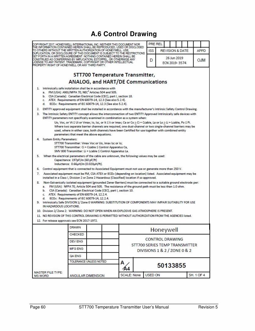
Page 60 STT700 Temperature Transmitter User’s Manual Revision 5
A.6 Control Drawing

Revision 5 STT700 Temperature Transmitter User’s Manual Page 61
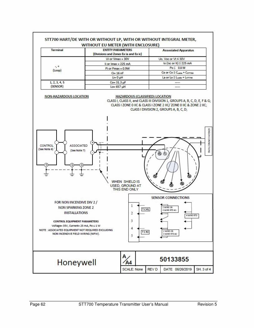
Page 62 STT700 Temperature Transmitter User’s Manual Revision 5
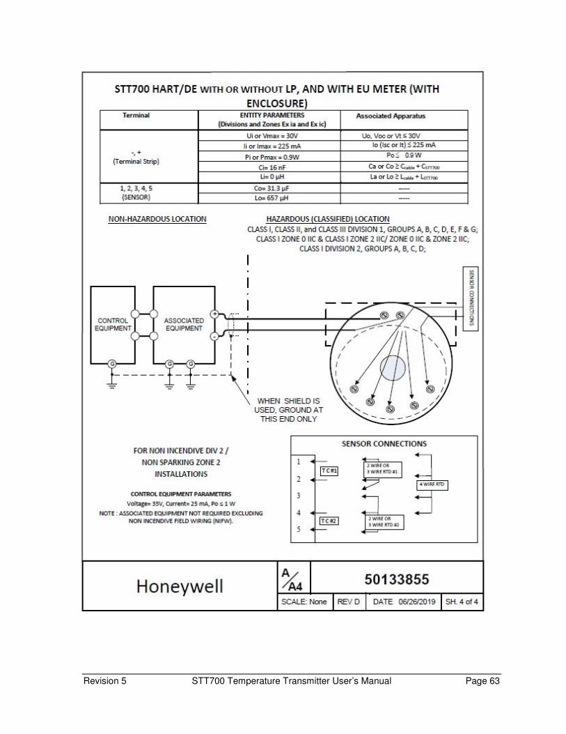
Revision 5 STT700 Temperature Transmitter User’s Manual Page 63

Page 64 STT700 Temperature Transmitter User’s Manual Revision 5
Glossary
AWG American Wire Gauge
C/J Cold Junction
CVD Callendar-Van Dusen is an equation that describe the relationship between
resistance (R) and temperature (t) of platinum resistance thermometers (RTD)
DD Device Description
DE Digital Enhanced Communications Mode
DTM Device Type Manager
EMI Electromagnetic Interference
EEPROM Electrically Erasable Programmable Read Only Memory
FDM Field Device Manager
FTA Field Termination Assembly
HART Highway Addressable Remote Transducer
HCF HART Communication Foundation
Hz Hertz
LRL Lower Range Limit
LRV Lower Range Value
mAdc Milliamperes Direct Current
MCT MC Toolkit
mV Millivolts
Nm Newton.meters
NPT National Pipe Thread
NVM Non-Volatile Memory
PM Process Manager
PV Process Variable
PWA Printed Wiring Assembly
RFI Radio Frequency Interference
RTD Resistance Temperature Detector
SAT Smartline anytime Tool to upgrade the firmware
SCT SmartLine Configuration Toolkit
SFC Smart Field Communicator
STIM Temperature Transmitter Interface Module
STIMV IOP Temperature Transmitter Interface Multivariable Input/Output Processor
T Temperature
T/C Thermocouple
URL Upper Range Limit
URV Upper Range Value
US Universal Station
Vac Volts Alternating Current
Vdc Volts Direct Current
WAO WRITE AS ONE (grouping of parameters for editing, for example you can
edit PV URV and PV LRV in one shot if URV LRV is provided under wao
list).

Revision 5 STT700 Temperature Transmitter User’s Manual Page 65
Index
A
About This Manual ..................................... iii
Accuracy ..................................................... 5
Application Design ...................................... 5
C
Copyrights, Notices and Trademarks............ ii
D
Diagnostic Messages ................................... 5
Display Options .......................................... 4
F
Features and Options .................................. 1 Functional Characteristics .......................................... 3
Physical Characteristics .............................................. 1
G
Glossary ................................................... 62
H
Honeywell MC Toolkit ................................. 9
I
Installation and Startup .............................. 9 Display Installation Precautions ................................. 9
Mounting STT850 Temperature Transmitters ............ 9
Site evaluation ........................................................... 9
Installation Site Evaluation Site Evaluation ........................................................... 9
Introduction ............................................... 1
M
Maintenance ............................................ 35 Preventive Maintenance Practices and Schedules ... 35
Replacing the Communication Module .................... 35
Mounting STT850 Temperature Transmitters
............................................................. 10 Mounting Dimentsions ............................................ 10
Summary ................................................................. 10
N
Name Plate ................................................. 3
O
Operation ................................................. 32
P
Patent Notice ............................................. iv
R
References ................................................. iv
Release Information ................................... iii
S
Safety Safety Integrity Level ................................................. 5
Safety Certification ..................................... 4
Startup ..................................................... 29 Constant Current Source Mode Procedure ............. 30
Output Check Procedures ........................................ 29
Support and Contact Information ............... iv
Symbol Descriptions and Definitions ........... v
T
Telephone and Email Contacts ................... iv
Temperature, Analog, HART and DE
Communication ..................................... 47
Transmitter Adjustments ............................ 4
W
Wiring a Transmitter ................................. 20 Wiring Variations ..................................................... 22
For more information To learn more about SmartLine transmitters, visit www.honeywellprocess.com Or contact your Honeywell Account Manager
Process Solutions Honeywell
1250 W Sam Houston Pkwy S Houston, TX 77042
Honeywell Control Systems Ltd Honeywell House, Skimped Hill Lane Bracknell, England, RG12 1EB
34-TT-25-17, Rev.5 July 2019
2019 Honeywell International Inc.
Shanghai City Centre, 100 Jungi Road Shanghai, China 20061 www.honeywellprocess.com
Sales and Service For application assistance, current specifications, pricing, or name of the nearest Authorized Distributor, contact one of the offices below.
ASIA PACIFIC Honeywell Process Solutions,
(TAC) [email protected]
Australia Honeywell Limited Phone: +(61) 7-3846 1255 FAX: +(61) 7-3840 6481 Toll Free 1300-36-39-36 Toll Free Fax: 1300-36-04-70 China – PRC - Shanghai Honeywell China Inc. Phone: (86-21) 5257-4568 Fax: (86-21) 6237-2826
Singapore Honeywell Pte Ltd. Phone: +(65) 6580 3278 Fax: +(65) 6445-3033 South Korea Honeywell Korea Co Ltd Phone: +(822) 799 6114 Fax: +(822) 792 9015
EMEA Honeywell Process Solutions,
Phone: + 80012026455 or +44 (0)1344 656000
Email: (Sales)
or
(TAC)
Web Knowledge Base search engine http://bit.ly/2N5Vldi
AMERICA’S Honeywell Process Solutions,
Phone: (TAC) 1-800-423-9883 or 215/641-3610
(Sales) 1-800-343-0228
Email: (Sales)
or
(TAC)
Web Knowledge Base search engine http://bit.ly/2N5Vldi