Embed Size (px)
Citation preview
5/2001
Ownerʼs Manual
450 Richard Street • Miamisburg, OH 45342Phone: (937) 866-0463 • Fax: (937) 866-4174
(800) 852-8352
CD700Solid StateCapacitor DischargeStud Welding System
CD 50 Stud Welder 0
CD700Solid StateCapacitor DischargeStud Welding System
Owner’s Manual• Installation
• Operation
• Maintenance
0 CD 50 Stud Welder
©2001 MIDWEST FASTENERS, INC., all rights reserved.450 Richard StreetMiamisburg, OH 45342Phone: (800) 852-8352Fax: (937) 866-4174
Warranty ......................................................................................... 4
Safety Precautions .......................................................................... 5
What is Stud Welding? ................................................................... 6
How Does CD Stud Welding Differ From ARC Stud Welding? .... 6
CD 700 Overview .......................................................................... 8
CD 700 Installation ........................................................................ 9
CD 700 Setup ............................................................................... 10
Gun Set Ups
Insulation Pins ........................................................................ 11
Insulation Pins with Internal Stop .......................................... 11
Weld Studs ............................................................................. 12
Cup Head Pins ........................................................................ 12
Controller Adjustment .................................................................. 13
Making A Test Weld ...................................................................... 13
Weld Quality ................................................................................. 14
Preventive Maintenance ................................................................ 15
Troubleshooting ............................................................................ 15
CD 700 Welder Specifications ..................................................... 18
CD 700 Welder Exploded View & Parts List ............................... 19
CD 2P Gun Specifications ............................................................ 20
CD 2P Gun Exploded View & Parts List ...................................... 21
CD 700 Electrical Schematic ........................................................ 22
Notes ............................................................................................. 23
TABLE OF CONTENTS
GENERAL
INTRODUCTION
INSTALLATION
SETUP& OPERATION
MAINTENANCETROUBLESHOOTING
SPECIFICATIONS
4 ©2001 MIDWEST FASTENERS, INC. — CD 700 Stud Welder
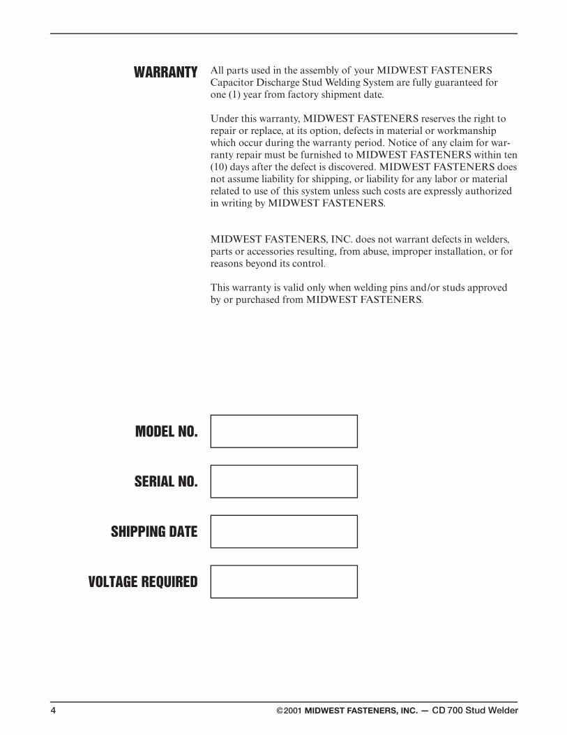
WARRANTY
MODEL NO.
SERIAL NO.
SHIPPING DATE
VOLTAGE REQUIRED
All parts used in the assembly of your MIDWEST FASTENERS Capacitor Discharge Stud Welding System are fully guaranteed for one (1) year from factory shipment date.
Under this warranty, MIDWEST FASTENERS reserves the right to repair or replace, at its option, defects in material or workmanship which occur during the warranty period. Notice of any claim for war-ranty repair must be furnished to MIDWEST FASTENERS within ten (10) days after the defect is discovered. MIDWEST FASTENERS does not assume liability for shipping, or liability for any labor or material related to use of this system unless such costs are expressly authorized in writing by MIDWEST FASTENERS.
MIDWEST FASTENERS, INC. does not warrant defects in welders, parts or accessories resulting, from abuse, improper installation, or for reasons beyond its control.
This warranty is valid only when welding pins and/or studs approved by or purchased from MIDWEST FASTENERS.
©2001 MIDWEST FASTENERS, INC. — CD 700 Stud Welder 5
SAFETYPRECAUTIONS
• Comply with all electrical, fire and other applicable codes or ordinancesin the installation and use of stud welding systems.
• Remove all combustible or volatile materials from the weld area.Although weld splatter resulting from stud welding is normally minimal,proper precautions should be taken when welding near or throughcombustible materials to insure that sparks or weld material do not comein contact with combustible material.
• Recommend wearing of eye protection at all times when welding.Spectacle type frames with Shade No. 3 absorptive and filter lens andside shields are suggested. Never look directly at the weld arc withoutwearing eye shields.
• Recommend use of proper ear protection with all CAPACITORDISCHARGE stud welding systems. The stud welding operator andanyone working within five (5) feet of the stud welding operation shoulduse ear protection devices.
• Use of protective clothing is suggested. Type of clothing will vary as toapplication, weld position and stud welding being used; however, in allcases, it should be fire resistant and sufficient to protect weldingoperator from weld splatter and material.
• Keep hands, clothing, etc. away from the weld stud, chuck and all otherparts in contact with them during the weld cycle.
• Keep weld cable and connectors in good condition. Inspect periodicallyfor broken insulation and/or other electrical hazards.
• Do not operate with worn or poorly connected cables. Inspect all cablesoften for bare or exposed wires, broken insulation layers and/or looseconnections. Repair all such connections before welding use.
• Do not stand in water or on damp surfaces while welding. Avoid wearingwet or sweaty clothes. Do not weld in the rain.
WARNING
Use extreme caution when servicing or troubleshootingany component of this stud welding system.If possible, turn all power controls “OFF”
and disconnect all electrical cables.
For other suggested precautions, safe practices, etc.regarding welding, refer to
“Safety in Welding and Cutting”,ANSI Z49.1, American National Standards Institute.
HIGH VOLTAGE
HEARINGPROTECTION
EYEPROTECTION
Stud welding is a welding process where a “stud” (or similar metal part) isinstantaneously end-joined to a metal workpiece. This process involves thesame basic principles and metallurgical aspects as any other weldingprocess.
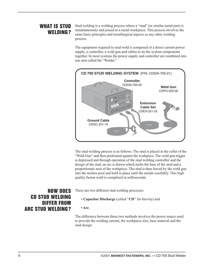
The equipment required to stud weld is composed of a direct current powersupply, a controller, a weld gun and cables to tie the system componentstogether. In most systems the power supply and controller are combined intoone unit called the “Welder.”
CD 700 STUD WELDING SYSTEM (P/N: CDSW-700-01)
The stud welding process is as follows. The stud is placed in the collet of the“Weld Gun” and then positioned against the workpiece. The weld gun triggeris depressed and through operation of the stud welding controller and thedesign of the stud, an arc is drawn which melts the base of the stud and aproportionate area of the workpiece. The stud is then forced by the weld guninto the molten pool and held in place until the metals resolidify. This highquality fusion weld is completed in milliseconds.
There are two different stud welding processes:
• Capacitor Discharge (called “CD” for brevity) and
• Arc.
The difference between these two methods involves the power source usedto provide the welding current, the workpiece size, base material and thestud design.
WELD VOLTAGE
CD 700
POWER
OFF
ON
G
ROUND CABLE
LOW
MIN MAX
VOLTAGE
CONTROL
HIGH
WELD
POWER
CD
CUPHEAD
CONTROL
G
UN
+
+
–
6 ©2001 MIDWEST FASTENERS, INC. — CD 700 Stud Welder
WHAT IS STUDWELDING ?
HOW DOESCD STUD WELDING
DIFFER FROMARC STUD WELDING ?
ControllerCDSW-700-00
Weld GunCDPG-200-06
Ground CableCDGC-201-15
ExtensionCable Set
CDES-201-25
©2001 MIDWEST FASTENERS, INC. — CD 700 Stud Welder 7
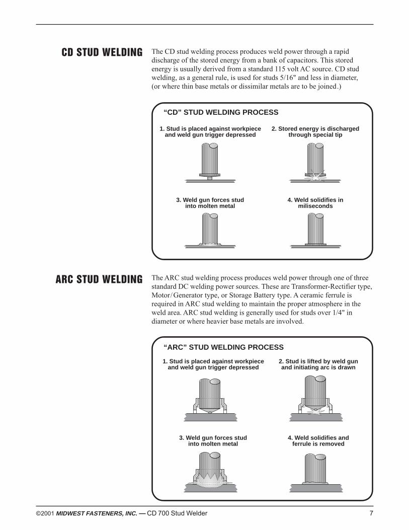
CD STUD WELDING The CD stud welding process produces weld power through a rapiddischarge of the stored energy from a bank of capacitors. This storedenergy is usually derived from a standard 115 volt AC source. CD studwelding, as a general rule, is used for studs 5/16" and less in diameter,(or where thin base metals or dissimilar metals are to be joined.)
“CD” STUD WELDING PROCESS
The ARC stud welding process produces weld power through one of threestandard DC welding power sources. These are Transformer-Rectifier type,Motor/Generator type, or Storage Battery type. A ceramic ferrule isrequired in ARC stud welding to maintain the proper atmosphere in theweld area. ARC stud welding is generally used for studs over 1/4" indiameter or where heavier base metals are involved.
“ARC” STUD WELDING PROCESS
ARC STUD WELDING
1. Stud is placed against workpieceand weld gun trigger depressed
2. Stored energy is dischargedthrough special tip
3. Weld gun forces studinto molten metal
4. Weld solidifies inmiliseconds
1. Stud is placed against workpieceand weld gun trigger depressed
2. Stud is lifted by weld gunand initiating arc is drawn
3. Weld gun forces studinto molten metal
4. Weld solidifies andferrule is removed
8 ©2001 MIDWEST FASTENERS, INC. — CD 700 Stud Welder
OVERVIEW – CD 700CAPACITOR DISCHARGE
STUD WELDER
The CD 700 is a capacitor discharge stud welder. The weld energy is storedin capacitors located inside the control unit. The amount of stored energycan be controlled by rotating the voltage control knob located on the frontpanel.
CD weld studs, or pins, used with the CD700 must have a speciallydesigned projection at the weld end. When the stud is inserted into the weldgun and placed against the workpiece, and the trigger switch is depressed,the following occurs:
1. The energy stored in the capacitors travels through the weld cables tothe stud.
2. The rapid rise in current ignites the projection and allows a weldingarc to be established between the stud and the workpiece.
3. The arc melts the base of the stud and a portion of the workpiece.
4. The spring pressure inside the welding gun forces the stud into themolten metal pool created by the arc.
5. The cycle ends upon contact of the stud to the workpiece.
6. The welding gun is then removed. Upon removal, the controller willautomatically recharge to the set voltage.
CAUTION
The noise generated by stud weldingmay exceed allowable levels
established by O.S.H.A. For this reasonit is recommended that proper ear protection be worn
by the operator and anyone working in the immediate area.
WARNING
Voltages inside the unit can reach 200 volts D.C.even if the unit is turned off. All repair work
should be handled by factory trained personnel.
HIGH VOLTAGE
HEARINGPROTECTION
©2001 MIDWEST FASTENERS, INC. — CD 700 Stud Welder 9
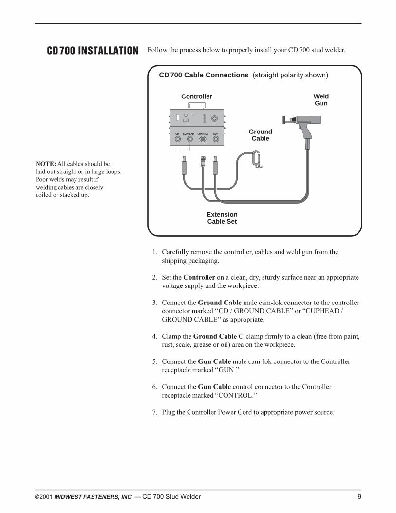
CD 700 INSTALLATION Follow the process below to properly install your CD700 stud welder.
CD700 Cable Connections (straight polarity shown)
1. Carefully remove the controller, cables and weld gun from theshipping packaging.
2. Set the Controller on a clean, dry, sturdy surface near an appropriatevoltage supply and the workpiece.
3. Connect the Ground Cable male cam-lok connector to the controllerconnector marked “CD / GROUND CABLE” or “CUPHEAD /GROUND CABLE” as appropriate.
4. Clamp the Ground Cable C-clamp firmly to a clean (free from paint,rust, scale, grease or oil) area on the workpiece.
5. Connect the Gun Cable male cam-lok connector to the Controllerreceptacle marked “GUN.”
6. Connect the Gun Cable control connector to the Controllerreceptacle marked “CONTROL.”
7. Plug the Controller Power Cord to appropriate power source.
NOTE: All cables should belaid out straight or in large loops.Poor welds may result ifwelding cables are closelycoiled or stacked up.
GroundCable
WeldGun
Controller
CD CUPHEAD CONTROL GUN
ExtensionCable Set
10 ©2001 MIDWEST FASTENERS, INC. — CD 700 Stud Welder
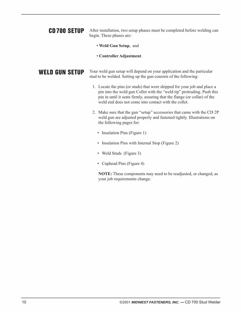
CD 700 SETUP After installation, two setup phases must be completed before welding canbegin. These phases are:
• Weld Gun Setup, and
• Controller Adjustment.
Your weld gun setup will depend on your application and the particularstud to be welded. Setting up the gun consists of the following:
1. Locate the pins (or studs) that were shipped for your job and place apin into the weld gun Collet with the “weld tip” protruding. Push thispin in until it seats firmly, assuring that the flange (or collar) of theweld end does not come into contact with the collet.
2. Make sure that the gun “setup” accessories that came with the CD 2Pweld gun are adjusted properly and fastened tightly. Illustrations onthe following pages for:
• Insulation Pins (Figure 1)
• Insulation Pins with Internal Stop (Figure 2)
• Weld Studs (Figure 3)
• Cuphead Pins (Figure 4)
NOTE: These components may need to be readjusted, or changed, asyour job requirements change.
WELD GUN SETUP
CD
CD
WeldPin
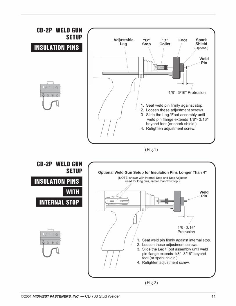
Optional Weld Gun Setup for Insulation Pins Longer Than 4"(NOTE: shown with Internal Stop and Stop Adjuster
used for long pins, rather than “B”-Stop.)
1/8 - 3/16"Protrusion
1. Seat weld pin firmly against internal stop.2. Loosen these adjustment screws.3. Slide the Leg / Foot assembly until weld
pin flange extends 1/8"- 3/16" beyondfoot (or spark shield.)
4. Retighten adjustment screw.
©2001 MIDWEST FASTENERS, INC. — CD 700 Stud Welder 11
CD-2P WELD GUNSETUP
INSULATION PINS .
WeldPin
1. Seat weld pin firmly against stop.2. Loosen these adjustment screws.3. Slide the Leg / Foot assembly until
weld pin flange extends 1/8"- 3/16"beyond foot (or spark shield.)
4. Retighten adjustment screw.
AdjustableLeg
Foot
1/8"- 3/16" Protrusion
“B”Collet
SparkShield
(Optional)
“B”Stop
CD-2P WELD GUNSETUP
INSULATION PINS .
WITH .
INTERNAL STOP .
(Fig.1)
(Fig.2)
CUPHEAD
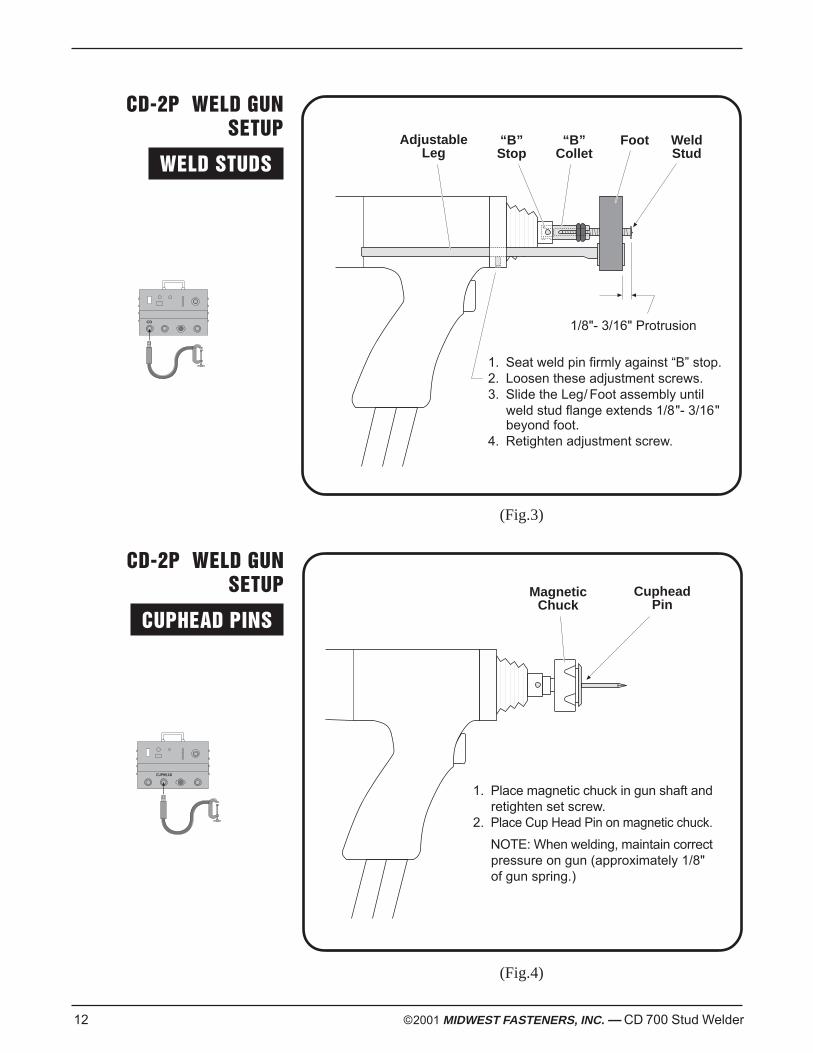
1. Seat weld pin firmly against “B” stop.2. Loosen these adjustment screws.3. Slide the Leg/ Foot assembly until
weld stud flange extends 1/8"- 3/16"beyond foot.
4. Retighten adjustment screw.
1/8"- 3/16" Protrusion
WeldStud
AdjustableLeg
Foot“B”Collet
“B”Stop
12 ©2001 MIDWEST FASTENERS, INC. — CD 700 Stud Welder
CD-2P WELD GUNSETUP
WELD STUDS .
CD-2P WELD GUNSETUP
CUPHEAD PINS .
(Fig.3)
(Fig.4)
CupheadPin
1. Place magnetic chuck in gun shaft andretighten set screw.
2. Place Cup Head Pin on magnetic chuck.
NOTE: When welding, maintain correctpressure on gun (approximately 1/8"of gun spring.)
MagneticChuck
CD
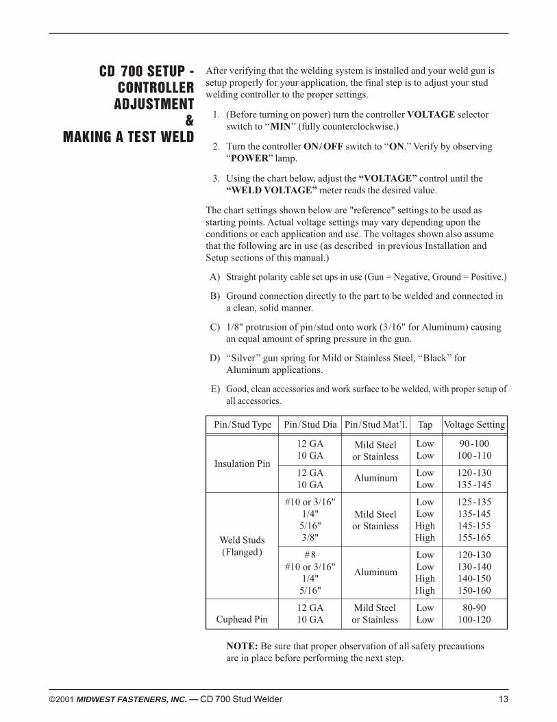
After verifying that the welding system is installed and your weld gun issetup properly for your application, the final step is to adjust your studwelding controller to the proper settings.
1. (Before turning on power) turn the controller VOLTAGE selectorswitch to “MIN” (fully counterclockwise.)
2. Turn the controller ON/ OFF switch to “ON.” Verify by observing“POWER” lamp.
3. Using the chart below, adjust the “VOLTAGE” control until the“WELD VOLTAGE” meter reads the desired value.
The chart settings shown below are "reference" settings to be used asstarting points. Actual voltage settings may vary depending upon theconditions or each application and use. The voltages shown also assumethat the following are in use (as described in previous Installation andSetup sections of this manual.)
A) Straight polarity cable set ups in use (Gun = Negative, Ground = Positive.)
B) Ground connection directly to the part to be welded and connected ina clean, solid manner.
C) 1/8" protrusion of pin/stud onto work (3/16" for Aluminum) causingan equal amount of spring pressure in the gun.
D) “Silver” gun spring for Mild or Stainless Steel, “Black” forAluminum applications.
E) Good, clean accessories and work surface to be welded, with proper setup ofall accessories.
Pin/Stud Type Pin/Stud Dia Pin/Stud Mat’l. Tap Voltage Setting
12 GA Low 90-10010 GA Low 100 -110
12 GA Low 120-13010 GA Low 135 -145
#10 or 3/16" Low 125-1351/4" Low 135-145
5/16" High 145-1553/8" High 155-165
#8 Low 120-130#10 or 3/16" Low 130-140
1/4" High 140-1505/16" High 150-160
12 GA Low 80-9010 GA Low 100-120
NOTE: Be sure that proper observation of all safety precautionsare in place before performing the next step.
©2001 MIDWEST FASTENERS, INC. — CD 700 Stud Welder 13
CD 700 SETUP -CONTROLLER
ADJUSTMENT&
MAKING A TEST WELD
Insulation Pin
Weld Studs(Flanged)
Cuphead Pin
Mild Steelor Stainless
Aluminum
Mild Steelor Stainless
Aluminum
Mild Steelor Stainless
4. Pick up the weld gun and place the stud firmly against the workpiece(The test workpiece should be a material that is similar to theworkpiece to be welded to in actual production.)
5. Depress the weld gun trigger, wait momentarily, and then pull the gunstraight back off the stud.
6. Test the weld integrity (see below.)
14 ©2001 MIDWEST FASTENERS, INC. — CD 700 Stud Welder
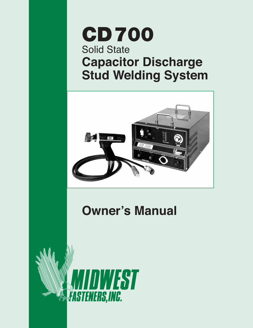
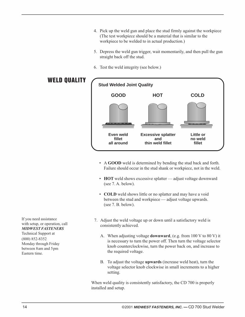
WELD QUALITYStud Welded Joint Quality
• A GOOD weld is determined by bending the stud back and forth.Failure should occur in the stud shank or workpiece, not in the weld.
• HOT weld shows excessive splatter — adjust voltage downward(see 7. A. below).
• COLD weld shows little or no splatter and may have a voidbetween the stud and workpiece — adjust voltage upwards.(see 7. B. below).
7. Adjust the weld voltage up or down until a satisfactory weld isconsistently achieved.
A. When adjusting voltage downward, (e.g. from 100 V to 80 V) itis necessary to turn the power off. Then turn the voltage selectorknob counterclockwise, turn the power back on, and increase tothe required voltage.
B. To adjust the voltage upwards (increase weld heat), turn thevoltage selector knob clockwise in small increments to a highersetting.
When weld quality is consistently satisfactory, the CD 700 is properlyinstalled and setup.
If you need assistancewith setup, or operation, callMIDWEST FASTENERSTechnical Support at(800) 852-8352Monday through Fridaybetween 8am and 5pmEastern time.
Even weldfillet
all around
Excessive splatterand
thin weld fillet
Little orno weld
fillet
GOOD HOT COLD
©2001 MIDWEST FASTENERS, INC. — CD 700 Stud Welder 15
PREVENTIVEMAINTENANCE
TROUBLESHOOTING
Your MIDWEST FASTENERS welder is designed for long service withminimal care. Ordinary common sense maintenance will keep it operatingefficiently. The following are a few tips on preventive maintenance.
1. Treat the cables with respect. Avoid sharp bends or kinks which maybreak the cables. DO NOT use the cables as a “ towline” to drag or liftthe controller. Avoid damaging or straining the cables where theyenter the gun or controller.
2. Louvers on the sides of the controller should be free fromobstructions at all times to prevent overheating.
3. Keep the controller and gun clean and dry, free of grease, water, dustand dirt. Do not lubricate any part of your CD 2P weld gun.
4. The weld gun is for welding studs only. Do not use the weld gun as amultipurpose tool (i.e., Hammer—banging studs to test welds orbreak ferrules, Scraper—removing rust, scale or weld splatter, etc.)
When troubleshooting the CD700, the following precautions must beobserved.
1. Controller power must be TURNED OFF!
NOTE: Dangerous voltage levels can still be present in thecontroller—even after power is disconnected.
2. The use of a volt/ohmmeter is recommended to verify where anyvoltage may, or may not, be present.
3. The use of a continuity tester (or trouble shooting light) can be usedfor continuity checking (disconnected) cables only.
The troubleshooting chart on the following pages can assist in locating andfixing problems with the CD700.
HIGH VOLTAGE
16 ©2001 MIDWEST FASTENERS, INC. — CD 700 Stud Welder
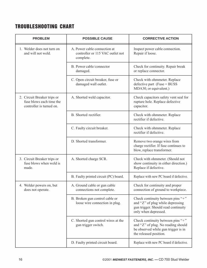
PROBLEM POSSIBLE CAUSE CORRECTIVE ACTION
TROUBLESHOOTING CHART
1. Welder does not turn onand will not weld.
2. Circuit Breaker trips orfuse blows each time thecontroller is turned on.
3. Circuit Breaker trips orfuse blows when weld ismade.
4. Welder powers on, butdoes not operate.
A. Power cable connection atcontroller or 115 VAC outlet notcomplete.
B. Power cable/connectordamaged.
C. Open circuit breaker, fuse ordamaged wall outlet.
A. Shorted weld capacitor.
B. Shorted rectifier.
C. Faulty circuit breaker.
D. Shorted transformer.
A. Shorted charge SCR.
B. Faulty printed circuit (PC) board.
A. Ground cable or gun cableconnections not complete.
B. Broken gun control cable orloose wire connection in plug.
C. Shorted gun control wires at thegun trigger switch.
D. Faulty printed circuit board.
Inspect power cable connection.Repair if loose.
Check for continuity. Repair breakor replace connector.
Check with ohmmeter. Replacedefective part (Fuse = BUSSMDA30, or equivalent.)
Check capacitors safety vent seal forrupture hole. Replace defectivecapacitor.
Check with ohmmeter. Replacerectifier if defective.
Check with ohmmeter. Replacerectifier if defective.
Remove two orange wires fromcharge rectifier. If fuse continues toblow, replace transformer.
Check with ohmmeter. (Should notshow continuity in either direction.)Replace if defective.
Replace with new PC board if defective.
Check for continuity and properconnection of ground to workpiece.
Check continuity between pins “+”and “Z” of plug while depressinggun trigger. Should read continuityonly when depressed.
Check continuity between pins “+”and “Z” of plug. No reading shouldbe observed while gun trigger is inthe released position.
Replace with new PC board if defective.
©2001 MIDWEST FASTENERS, INC. — CD 700 Stud Welder 17
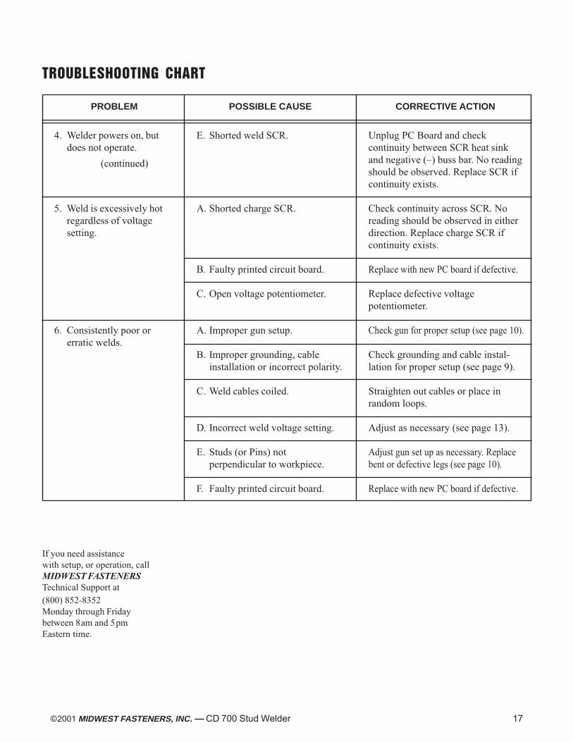
TROUBLESHOOTING CHART
4. Welder powers on, butdoes not operate.
5. Weld is excessively hotregardless of voltagesetting.
6. Consistently poor orerratic welds.
E. Shorted weld SCR.
A. Shorted charge SCR.
B. Faulty printed circuit board.
C. Open voltage potentiometer.
A. Improper gun setup.
B. Improper grounding, cableinstallation or incorrect polarity.
C. Weld cables coiled.
D. Incorrect weld voltage setting.
E. Studs (or Pins) notperpendicular to workpiece.
F. Faulty printed circuit board.
Unplug PC Board and checkcontinuity between SCR heat sinkand negative (–) buss bar. No readingshould be observed. Replace SCR ifcontinuity exists.
Check continuity across SCR. Noreading should be observed in eitherdirection. Replace charge SCR ifcontinuity exists.
Replace with new PC board if defective.
Replace defective voltagepotentiometer.
Check gun for proper setup (see page 10).
Check grounding and cable instal-lation for proper setup (see page 9).
Straighten out cables or place inrandom loops.
Adjust as necessary (see page 13).
Adjust gun set up as necessary. Replacebent or defective legs (see page 10).
Replace with new PC board if defective.
(continued)
PROBLEM POSSIBLE CAUSE CORRECTIVE ACTION
If you need assistancewith setup, or operation, callMIDWEST FASTENERSTechnical Support at(800) 852-8352Monday through Fridaybetween 8am and 5pmEastern time.
WELD VOLTAGE
CD 700
POWER
OFF
ON
G
ROUND CABLE
LOW
MIN MAX
VOLTAGE
CONTROL
HIGH
WELD
POWER
CD
CUPHEAD
CONTROL
G
UN
+
+
–
21"
9"
13 "
18 ©2001 MIDWEST FASTENERS, INC. — CD 700 Stud Welder
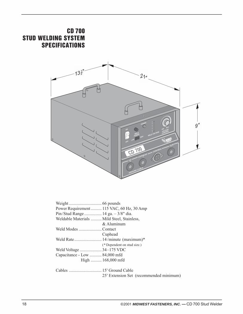
CD 700STUD WELDING SYSTEM
SPECIFICATIONS
Weight .............................. 66 poundsPower Requirement .......... 115 VAC, 60 Hz, 30 AmpPin/Stud Range ................ 14 ga. – 3/8" dia.Weldable Materials .......... Mild Steel, Stainless,
& AluminumWeld Modes ..................... Contact
CupheadWeld Rate ......................... 14 /minute (maximum)*
(* Dependent on stud size.)
Weld Voltage .................... 34–175 VDCCapacitance - Low ........... 84,000 mfd
High .......... 168,000 mfd
Cables .............................. 15' Ground Cable25' Extension Set (recommended minimum)
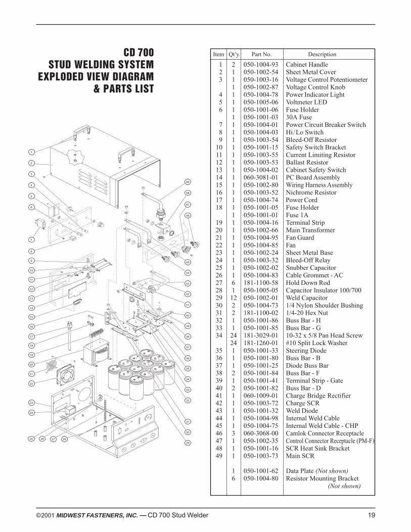
CD 700STUD WELDING SYSTEM
EXPLODED VIEW DIAGRAM& PARTS LIST
©2001 MIDWEST FASTENERS, INC. — CD 700 Stud Welder 19
Item Qt’y. Part No. Description
1 2 050-1004-93 Cabinet Handle2 1 050-1002-54 Sheet Metal Cover3 1 050-1003-16 Voltage Control Potentiometer
1 050-1002-87 Voltage Control Knob4 1 050-1004-78 Power Indicator Light5 1 050-1005-06 Voltmeter LED6 1 050-1001-06 Fuse Holder
1 050-1001-03 30A Fuse7 1 050-1004-01 Power Circuit Breaker Switch8 1 050-1004-03 Hi/Lo Switch9 1 050-1003-54 Bleed-Off Resistor
10 1 050-1001-15 Safety Switch Bracket11 1 050-1003-55 Current Limiting Resistor12 1 050-1003-53 Ballast Resistor13 1 050-1004-02 Cabinet Safety Switch14 1 060-3081-01 PC Board Assembly15 1 050-1002-80 Wiring Harness Assembly16 1 050-1003-52 Nichrome Resistor17 1 050-1004-74 Power Cord18 1 050-1001-05 Fuse Holder
1 050-1001-01 Fuse 1A19 1 050-1004-16 Terminal Strip20 1 050-1002-66 Main Transformer21 1 050-1004-95 Fan Guard22 1 050-1004-85 Fan23 1 050-1002-24 Sheet Metal Base24 1 050-1003-32 Bleed-Off Relay25 1 050-1002-02 Snubber Capacitor26 1 050-1004-83 Cable Grommet - AC27 6 181-1100-58 Hold Down Rod28 1 050-1005-05 Capacitor Insulator 100/70029 12 050-1002-01 Weld Capacitor30 2 050-1004-73 1/4 Nylon Shoulder Bushing31 2 181-1100-02 1/4-20 Hex Nut32 1 050-1001-86 Buss Bar - H33 1 050-1001-85 Buss Bar - G34 24 181-3029-01 10-32 x 5/8 Pan Head Screw
24 181-1260-01 #10 Split Lock Washer35 1 050-1001-33 Steering Diode36 1 050-1001-80 Buss Bar - B37 1 050-1001-25 Diode Buss Bar38 2 050-1001-84 Buss Bar - F39 1 050-1001-41 Terminal Strip - Gate40 2 050-1001-82 Buss Bar - D41 1 060-1009-01 Charge Bridge Rectifier42 1 050-1003-72 Charge SCR43 1 050-1001-32 Weld Diode44 1 050-1004-98 Internal Weld Cable45 1 050-1004-75 Internal Weld Cable - CHP46 3 060-3068-00 Camlok Connector Receptacle47 1 050-1002-35 Control Connector Receptacle (PM-F)48 1 050-1001-16 SCR Heat Sink Bracket49 1 050-1003-73 Main SCR
1 050-1001-62 Data Plate (Not shown)6 050-1004-80 Resistor Mounting Bracket
(Not shown)
11
25 27
3
4
5
6
8
9
10
14
15
16
17
18
19
20
21
22
23
2
1
43
42
41
40
39
36
35
34
33
32
31
30
26
13
12
28
7
24
38
45
44
47
46
49
48
37
29
20 ©2001 MIDWEST FASTENERS, INC. — CD 700 Stud Welder
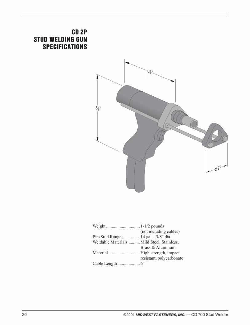
Weight .............................. 1-1/2 pounds(not including cables)
Pin/Stud Range ................ 14 ga. – 3/8" dia.Weldable Materials .......... Mild Steel, Stainless,
Brass & AluminumMaterial ............................ High strength, impact
resistant, polycarbonateCable Length.................... 6'
CD 2PSTUD WELDING GUN
SPECIFICATIONS
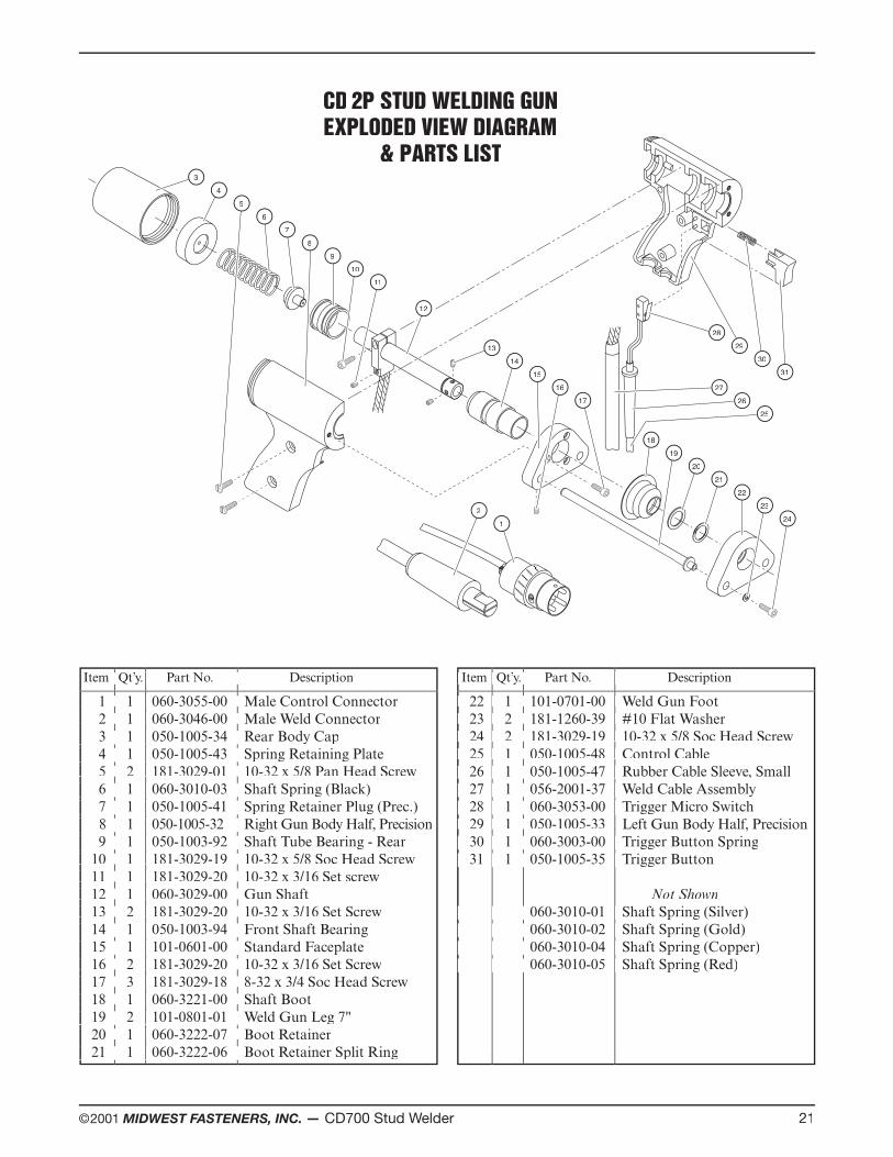
©2001 MIDWEST FASTENERS, INC. — CD700 Stud Welder 21
Item Qt’y. Part No. Description’y. Part No. Description’Item Qt y. Part No. Description
1 1 060-3055-00 Male Control Connector 1 1 060-3055-00 Male Control Connector 1 1 060-3055-00 Male Control Connector 1 1 060-3055-00 Male Control Connector 2 1 060-3046-00 Male Weld Connector 2 1 060-3046-00 Male Weld Connector 2 1 060-3046-00 Male Weld Connector 2 1 060-3046-00 Male Weld Connector 3 1 050-1005-34 Rear Body Cap 3 1 050-1005-34 Rear Body Cap 3 1 050-1005-34 Rear Body Cap 3 1 050-1005-34 Rear Body Cap 4 1 050-1005-43 Spring Retaining Plate 4 1 050-1005-43 Spring Retaining Plate 4 1 050-1005-43 Spring Retaining Plate 4 1 050-1005-43 Spring Retaining Plate 5 2 181-3029-01 10-32 x 5/8 Pan Head Screw 5 2 181-3029-01 10-32 x 5/8 Pan Head Screw 5 2 181-3029-01 10-32 x 5/8 Pan Head Screw 5 2 181-3029-01 10-32 x 5/8 Pan Head Screw 6 1 060-3010-03 Shaft Spring (Black) 6 1 060-3010-03 Shaft Spring (Black) 6 1 060-3010-03 Shaft Spring (Black) 6 1 060-3010-03 Shaft Spring (Black) 7 1 050-1005-41 Spring Retainer Plug (Prec.) 7 1 050-1005-41 Spring Retainer Plug (Prec.) 7 1 050-1005-41 Spring Retainer Plug (Prec.) 7 1 050-1005-41 Spring Retainer Plug (Prec.) 8 1 050-1005-32 Right Gun Body Half, Precision 8 1 050-1005-32 Right Gun Body Half, Precision 8 1 050-1005-32 Right Gun Body Half, Precision 8 1 050-1005-32 Right Gun Body Half, Precision 9 1 050-1003-92 Shaft Tube Bearing - Rear 9 1 050-1003-92 Shaft Tube Bearing - Rear 9 1 050-1003-92 Shaft Tube Bearing - Rear 9 1 050-1003-92 Shaft Tube Bearing - Rear 10 1 181-3029-19 10-32 x 5/8 Soc Head Screw 10 1 181-3029-19 10-32 x 5/8 Soc Head Screw 10 1 181-3029-19 10-32 x 5/8 Soc Head Screw 10 1 181-3029-19 10-32 x 5/8 Soc Head Screw 11 1 181-3029-20 10-32 x 3/16 Set screw 11 1 181-3029-20 10-32 x 3/16 Set screw 11 1 181-3029-20 10-32 x 3/16 Set screw 11 1 181-3029-20 10-32 x 3/16 Set screw 12 1 060-3029-00 Gun Shaft 12 1 060-3029-00 Gun Shaft 12 1 060-3029-00 Gun Shaft 12 1 060-3029-00 Gun Shaft 13 2 181-3029-20 10-32 x 3/16 Set Screw 13 2 181-3029-20 10-32 x 3/16 Set Screw 13 2 181-3029-20 10-32 x 3/16 Set Screw 13 2 181-3029-20 10-32 x 3/16 Set Screw 14 1 050-1003-94 Front Shaft Bearing 14 1 050-1003-94 Front Shaft Bearing 14 1 050-1003-94 Front Shaft Bearing 14 1 050-1003-94 Front Shaft Bearing 15 1 101-0601-00 Standard Faceplate 15 1 101-0601-00 Standard Faceplate 15 1 101-0601-00 Standard Faceplate 15 1 101-0601-00 Standard Faceplate 16 2 181-3029-20 10-32 x 3/16 Set Screw 16 2 181-3029-20 10-32 x 3/16 Set Screw 16 2 181-3029-20 10-32 x 3/16 Set Screw 16 2 181-3029-20 10-32 x 3/16 Set Screw 17 3 181-3029-18 8-32 x 3/4 Soc Head Screw 17 3 181-3029-18 8-32 x 3/4 Soc Head Screw 17 3 181-3029-18 8-32 x 3/4 Soc Head Screw 17 3 181-3029-18 8-32 x 3/4 Soc Head Screw 18 1 060-3221-00 Shaft Boot 18 1 060-3221-00 Shaft Boot 18 1 060-3221-00 Shaft Boot 18 1 060-3221-00 Shaft Boot 19 2 101-0801-01 Weld Gun Leg 7" 19 2 101-0801-01 Weld Gun Leg 7" 19 2 101-0801-01 Weld Gun Leg 7" 19 2 101-0801-01 Weld Gun Leg 7" 20 1 060-3222-07 Boot Retainer 20 1 060-3222-07 Boot Retainer 20 1 060-3222-07 Boot Retainer 20 1 060-3222-07 Boot Retainer 21 1 060-3222-06 Boot Retainer Split Ring 21 1 060-3222-06 Boot Retainer Split Ring 21 1 060-3222-06 Boot Retainer Split Ring 21 1 060-3222-06 Boot Retainer Split Ring 21 1 060-3222-06 Boot Retainer Split Ring
22 1 101-0701-00 Weld Gun Foot 22 1 101-0701-00 Weld Gun Foot 23 2 181-1260-39 #10 Flat Washer 23 2 181-1260-39 #10 Flat Washer 24 2 181-3029-19 10-32 x 5/8 Soc Head Screw 24 2 181-3029-19 10-32 x 5/8 Soc Head Screw 25 1 050-1005-48 Control Cable 25 1 050-1005-48 Control Cable 26 1 050-1005-47 Rubber Cable Sleeve, Small 26 1 050-1005-47 Rubber Cable Sleeve, Small 27 1 056-2001-37 Weld Cable Assembly 27 1 056-2001-37 Weld Cable Assembly 28 1 060-3053-00 Trigger Micro Switch 28 1 060-3053-00 Trigger Micro Switch 29 1 050-1005-33 29 1 050-1005-33 Left Gun Body Half, Precision 30 1 060-3003-00 Trigger Button Spring 30 1 060-3003-00 Trigger Button Spring 31 1 050-1005-35 Trigger Button 31 1 050-1005-35 Trigger Button
Not Shown 060-3010-01 Shaft Spring (Silver) 060-3010-01 Shaft Spring (Silver) 060-3010-02 Shaft Spring (Gold) 060-3010-02 Shaft Spring (Gold) 060-3010-04 Shaft Spring (Copper) 060-3010-04 Shaft Spring (Copper) 060-3010-05 Shaft Spring (Red) 060-3010-05 Shaft Spring (Red)
y. Part No. Description
1 1 060-3055-00 Male Control Connector 2 1 060-3046-00 Male Weld Connector 3 1 050-1005-34 Rear Body Cap 4 1 050-1005-43 Spring Retaining Plate 5 2 181-3029-01 10-32 x 5/8 Pan Head Screw 6 1 060-3010-03 Shaft Spring (Black) 7 1 050-1005-41 Spring Retainer Plug (Prec.) 8 1 050-1005-32 Right Gun Body Half, Precision 9 1 050-1003-92 Shaft Tube Bearing - Rear 10 1 181-3029-19 10-32 x 5/8 Soc Head Screw 11 1 181-3029-20 10-32 x 3/16 Set screw 12 1 060-3029-00 Gun Shaft 13 2 181-3029-20 10-32 x 3/16 Set Screw 14 1 050-1003-94 Front Shaft Bearing 15 1 101-0601-00 Standard Faceplate 16 2 181-3029-20 10-32 x 3/16 Set Screw 17 3 181-3029-18 8-32 x 3/4 Soc Head Screw 18 1 060-3221-00 Shaft Boot 19 2 101-0801-01 Weld Gun Leg 7" 20 1 060-3222-07 Boot Retainer 21 1 060-3222-06 Boot Retainer Split Ring
Item Qt Item Qt’y. Part No. Description’y. Part No. Description’ Item Qt
22 1 101-0701-00 Weld Gun Foot 23 2 181-1260-39 #10 Flat Washer 24 2 181-3029-19 10-32 x 5/8 Soc Head Screw 25 1 050-1005-48 Control Cable 26 1 050-1005-47 Rubber Cable Sleeve, Small 27 1 056-2001-37 Weld Cable Assembly 28 1 060-3053-00 Trigger Micro Switch 29 1 050-1005-33 30 1 060-3003-00 Trigger Button Spring 31 1 050-1005-35 Trigger Button
060-3010-01 Shaft Spring (Silver) 060-3010-02 Shaft Spring (Gold) 060-3010-04 Shaft Spring (Copper) 060-3010-05 Shaft Spring (Red)
y. Part No. Description
22 1 101-0701-00 Weld Gun Foot 23 2 181-1260-39 #10 Flat Washer 24 2 181-3029-19 10-32 x 5/8 Soc Head Screw 25 1 050-1005-48 Control Cable 26 1 050-1005-47 Rubber Cable Sleeve, Small 27 1 056-2001-37 Weld Cable Assembly 28 1 060-3053-00 Trigger Micro Switch
30 1 060-3003-00 Trigger Button Spring 31 1 050-1005-35 Trigger Button
060-3010-01 Shaft Spring (Silver) 060-3010-02 Shaft Spring (Gold) 060-3010-04 Shaft Spring (Copper) 060-3010-05 Shaft Spring (Red)
y. Part No. Description
22 1 101-0701-00 Weld Gun Foot 23 2 181-1260-39 #10 Flat Washer 24 2 181-3029-19 10-32 x 5/8 Soc Head Screw 25 1 050-1005-48 Control Cable 26 1 050-1005-47 Rubber Cable Sleeve, Small 27 1 056-2001-37 Weld Cable Assembly 28 1 060-3053-00 Trigger Micro Switch 29 1 050-1005-33 30 1 060-3003-00 Trigger Button Spring 31 1 050-1005-35 Trigger Button
060-3010-01 Shaft Spring (Silver) 060-3010-02 Shaft Spring (Gold) 060-3010-04 Shaft Spring (Copper) 060-3010-05 Shaft Spring (Red)
CD 2P STUD WELDING GUNEXPLODED VIEW DIAGRAM
& PARTS LIST
2324
13131414
15151616
17
1819
2021
22
34
56
78
910
11
12
28282929
30303131
21
25
2726
22 ©2001 MIDWEST FASTENERS, INC. — CD 700 Stud Welder
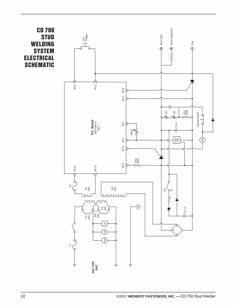
CD 700STUD
WELDINGSYSTEM
ELECTRICALSCHEMATIC
CR
Fan
R
F1
115
/220
VA
C
A
150
VA
C
24 VA
C
110
VA
C
A
+ –
CB
+
Cab
inet
Sw
itchCR
C7-
12
5KΩ
25W
50Ω
50W
25K
Ω
CR
Gun
Trig
ger
Wor
k (C
D)
Wor
k (C
uphe
ad)
Gun
IPL
8
IPL1
0
IPL6
IPL
2
IPL
5IP
L3
IPL
7IP
L1IP
L4
IPL
9
P.C
. Bo
ard
060-
3081
-01
Rev
. 1
F2
220
VA
C
110
VA
C
+H
I
LO
LED
VM
C1-
6

NOTES
©2001 MIDWEST FASTENERS, INC. — CD 700 Stud Welder 23


3/2015
Ownerʼs Manual
450 Richard Street • Miamisburg, OH 45342Phone: (937) 866-0463 • Fax: (937) 866-4174
(800) 852-8352
CD700Solid StateCapacitor DischargeStud Welding System