Embed Size (px)
Citation preview
IOSUD - Universitatea Politehnica Timişoara
Şcoala Doctorală de Studii Inginereşti
STUDIES CONCERNING THE BEHAVIOUR OF MASONRY
WALLS UNDER SEISMIC ACTIONS. STRENGTHENING OF
MASONRY WALLS USING COMPOSITE MATERIALS
PhD Thesis – Summary
for obtaining the scientific title of doctor at
Politehnica University Timișoara
in the Civil Engineering PhD field
author eng. Eleonora Eva PARTENE
scientific coordinator Prof. PhD eng. Valeriu STOIAN
November 2018
Abstract
The PhD thesis aims to study the behaviour of masonry walls built-up using ceramic
blocks with vertical hollows, under seismic action. The thesis also studies the strengthening of
masonry walls using composite materials.
The experimental program focused on testing unreinforced masonry walls and
reinforced masonry walls, under horizontal cyclic loading and observing the difference
between these types of walls in initial state. The second part consisted on strengthening the
tested walls using fiber reinforced polymers and testing the walls again, in order to determine
if the walls with applied strengthening materials are able to regain their initial capacity or
even increase it. The efficiency of the strengthening method is assessed in the final chapter, at
the end of the experimental program.
At the end of the PhD thesis there is presented a case study for a real building, made
with load-initialing masonry walls, using the same ceramic blocks from our experimental
program. A theoretical evaluation is made according to the romanian standard P100-1/2013
and then a evalution using a software, in order to observe the spatial behaviour of the entire
building. The results for the case-study are compared with the results of the experimental
program, in order to observe the maximum capacity of the masonry walls from the building
and the maximum shear capacity from the experimental program.
1. INTRODUCTION
1.1. Overview
Masonry represents one of the oldest building material and is still used often nowadays.
However due to the lack of knowledge, many types of masonry structures have been built
without taking into account the horizontal loads that this buildings are going to be subjected to
over the years. Thus, there are a large number of buildings vulnerable to seismic actions, built
without any reference to seismic design rules, designed only for gravitational vertical loads.
However, in order to be able to successfully build masonry structures in seismic areas
such as our country, a series of measures are being taken to strengthen it, namely the use of
reinforced masonry, which by the presence of tie-columns and tie-beams, or the reinforcement
of the horizontal bed mortar joints, allows a better energy dissipation of seismic energy.
It is also recommended that in seismic areas to realize concrete rigid slabs for a better
behaviour under seismic loads.
1.2. Motivation
The main objective of the PhD thesis is the study of the behaviour of masonry walls
built up with ceramic block with vertical hollows, unreinforced or confined, under seismic
actions. The second part is the study of the behaviour of the strengthening of damaged masonry
walls, using composite materials, also under seismic action.
1.3. General framework
The PhD thesis was carried out in the Civil Engineering and Building Services
Department, Civil Engineering Faculty, Politehnica University Timișoara.
2. SUMMARY OF THE DESIGN CODE RULES FOR MASONRY
BUILDINGS
2.1. Design rules – according to romanian code: CR6-2013
The CR6 code makes a classification of masonry structures and contains design rules
for structures with load initialing walls, but also other types of walls.
The most important aspect in determinining the type of masonry to be used in a structure
is the knowledge of their classification:
Unreinforced masonry (URM) is the masonry that does not contain enough
reinforcement to fit into the reinforced category. [1]
Confined masonry (RC) is the masonry with concrete tie-columns and tie-beams on
all the sides of the wall. [1]
Confined masonry and reinforced masonry is the confined masonry that also has
reinforcement (materials with good tensile strength) in horizontal bed mortar joints, in order to
increase the shear capacity and the ductility of the masonry walls. Fig. 2.1.a [1]
Reinforced masonry is the masonry that has between two layers of masonry, a layer of
reinforced concrete/mortar with vertical reinforcement, with or without mechanical connections
between layers and in which all components have a contribution for gravitational and horizontal
loads. Fig. 2.1.b [1]
Infill masonry is the masonry used in concrete or steel structures with no load initialing
part, but can contribute in some cases to the lateral stiffness and to the energy dissipation of the
building. [1]
Another classification of the masonry can be: structural walls, structural stiffening walls
and nonstructural or framed walls. [1]
The present paper only refer to structural, load-bearing walls designed to withstand
vertical and horizontal in-plane loads. [1]
Structural load-initialing masonry walls are used for: buildings with maximum 5 storey

height, depending on the seismic area, used for housing or similar functions, social-cultural
buildings where large free spaces are not required, or hall buildings with moderate openings.
[1]
a) b)
Fig. 2.1. Masonry wall design:
a – confined masonry; b – reinforced masonry [1]
2.2. Design rules – according to romanian code: P100-1/2013
Romania’s territory is divided intro several seismic hazard areas (Fig. 2.2.), which are
considered constant in each area. The seismic hazard is represented as the peak value of seismic
ground acceleration ag, which is determined for an average recurrence period (IMR). [2]
Fig.2.2. Zoning map of ag values in Romania for IMR=225 years and 20% probability of
overtaking in 50 years
The design code makes a clear distinction between structural load initialing walls and
stiffening encreasing structural walls, so the structural load initialing walls are able to support
vertical and horizontal in-plane loads and the stiffening encreasing walls are the walls that help
the spatial conformation and cooperation of a building walls, and also helps the stability of the
wall linked to it. [3]
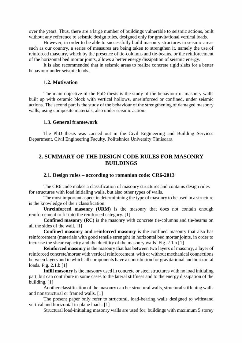
At the moment, several types of masonry elements can be used for structural load
initialing walls: clay blocks with or without vertical hollows (SR EN 771-1) or autoclaved
cellular concrete blocks (BCA) (SR EN 771-4). These elements are divided into group 1 or 2
of materials, with properties according to table 8.1. of P100-1. (table 2.1) [3]
Table 2.1. Geometrical properties of masonry blocks [3]
Characteristics Group 1
- clay și
BCA
Group 2 – Clay blocks with vertical
hollows
Total hollow volume
(% from gross volume)
≤25% ag≤0,15g ag≥0,20g
>25%; ≤55% >25%; ≤45%
Each hollow volume
(% from gross volume)
≤12,5% *for each of the multiple hollows ≤2%
*total handling hollows ≤12,5%
Declared value of the
thickness of the interior
and exterior walls
(mm)
No
demands
interior wall exterior wall
ag≤0,15g ag≥0,20g ag≤0,15g ag≥0,20g
≥5 ≥10 ≥8 ≥12
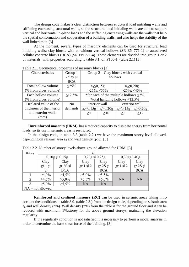
Unreinforced masonry (URM) has a reduced capacity to dissipate energy from horizontal
loads, so its use in seismic areas is restricted.
In the design code, in table 8.8 (table 2.2.) we have the maximum storey level allowed,
depending on seismic area ag and wall density (p%). [3]
Table 2.2. Number of storey levels above ground allowed for URM [3]
nstorey ag
0,10g și 0,15g 0,20g și 0,25g 0,30g÷0,40g
Clay
gr.1 și
2
Clay
gr.2S și
BCA
Clay
gr.1 și 2
Clay
gr.2S și
BCA
Clay
gr.1 și 2
Clay
gr.2S și
BCA
1 ≥4,0% ≥4,5% ≥5,0% ≥5,5%
NA
NA 2 ≥4,5% ≥5,0% ≥5,5% ≥6,0%
3 ≥5,0% ≥5,5% NA NA
NA – not allowed
Reinforced and confined masonry (RC) can be used in seismic areas taking intro
account the conditions in table 8.9. (table 2.3.) from the design code, depending on seismic area
ag and wall density (p%). Wall density (p%) from the table is for the ground floor and it can be
reduced with maximum 1%/storey for the above ground storeys, maintaing the elevation
regularity.
If the regularity condition is not satisfied it is necessary to perform a modal analysis in
order to determine the base shear force of the building. [3]
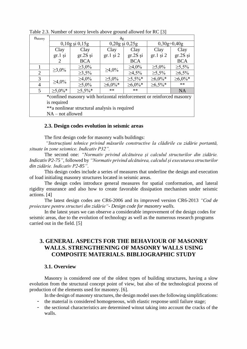
Table 2.3. Number of storey levels above ground allowed for RC [3]
nstorey ag
0,10g și 0,15g 0,20g și 0,25g 0,30g÷0,40g
Clay
gr.1 și
2
Clay
gr.2S și
BCA
Clay
gr.1 și 2
Clay
gr.2S și
BCA
Clay
gr.1 și 2
Clay
gr.2S și
BCA
1 ≥3,0%
≥3,0% ≥4,0%
≥4,0% ≥5,0% ≥5,5%
2 ≥3,5% ≥4,5% ≥5,5% ≥6,5%
3 ≥4,0%
≥4,0% ≥5,0% ≥5,5%* ≥6,0%* ≥6,0%*
4 ≥5,0% ≥6,0%* ≥6,0%* ≥6,5%* **
5 ≥5,0%* ≥5,5%* ** ** NA
*confined masonry with horizontal reinforcement or reinforced masonry
is required
**a nonlinear structural analysis is required
NA – not allowed
2.3. Design codes evolution in seismic areas
The first design code for masonry walls buildings:
“Instrucțiuni tehnice privind măsurile constructive la clădirile cu zidărie portantă,
situate în zone seismice. Indicativ P32”.
The second one: “Normativ privind alcătuirea și calculul structurilor din zidărie.
Indicativ P2-75”, followed by “Normativ privind alcătuirea, calculul și executarea structurilor
din zidărie. Indicativ P2-85”.
This design codes include a series of measures that underline the design and execution
of load initialing masonry structures located in seismic areas.
The design codes introduce general measures for spatial conformation, and lateral
rigidity ensurance and also how to create favorable dissipation mechanism under seismic
actions. [4]
The latest design codes are CR6-2006 and its improved version CR6-2013 “Cod de
proiectare pentru structuri din zidărie“- Design code for masonry walls.
In the latest years we can observe a considerable improvement of the design codes for
seismic areas, due to the evolution of technology as well as the numerous research programs
carried out in the field. [5]
3. GENERAL ASPECTS FOR THE BEHAVIOUR OF MASONRY
WALLS. STRENGTHENING OF MASONRY WALLS USING
COMPOSITE MATERIALS. BIBLIOGRAPHIC STUDY
3.1. Overview
Masonry is considered one of the oldest types of building structures, having a slow
evolution from the structural concept point of view, but also of the technological process of
production of the elements used for masonry. [6].
In the design of masonry structures, the design model uses the following simplifications:
- the material is considered homogeneous, with elastic response until failure stage;
- the sectional characteristics are determined witout taking into account the cracks of the
walls.
For the determination of design loads and resistance of the structural walls, using a
numerical or non-linear model, has to adequately represent the strength of the entire structural
system.
3.2. Failure modes for masonry walls
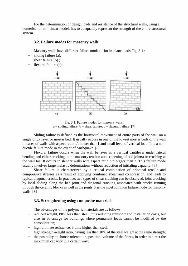
Masonry walls have different failure modes – for in-plane loads Fig. 3.1.:
- sliding failure (a);
- shear failure (b) ;
- flexural failure (c).
Fig. 3.1. Failure modes for masonry walls:
a – sliding failure; b – shear failure; c – flexural failure. [7]
Sliding failure is defined as the horizontal movement of entire parts of the wall on a
single brick layer or mortar bed. It usually occurs in one of the lowest mortar beds of the wall
in cases of walls with aspect ratio h/b lower than 1 and small level of vertical load. It is a non-
ductile failure mode in the event of earthquake. [8]
Flexural failure occurs when the wall behaves as a vertical cantilever under lateral
bending and either cracking in the masonry tension zone (opening of bed joints) or crushing at
the wall toe. It occurs in slender walls with aspect ratio h/b bigger than 2. This failure mode
usually involves large inelastic deformations without reduction of initialing capacity. [8]
Shear failure is characterized by a critical combination of principal tensile and
compressive stresses as a result of applying combined shear and compression, and leads to
typical diagonal cracks. In practice, two types of shear cracking can be observed, joint cracking
by local sliding along the bed joint and diagonal cracking associated with cracks running
through the ceramic blocks as well as the joints. It is the most common failure mode for masonry
walls. [8]
3.3. Strengthening using composite materials
The advantages of the polymeric materials are as follows:
- reduced weight, 80% less than steel, thus reducing transport and installation costs, but
also an advantage for buildings where permanent loads cannot be modified by the
consolidation;
- high ultimate resistance, 3 time higher than steel;
- high strength-weight ratio, having less than 10% of the steel weight at the same strength;
- the posibility to choose orientation, position, volume of the fibres, in order to direct the
maximum capacity in a certain way;
- high durability and posibility to use in agressive enviroments;
- dimensional stability, low thermal conductivity and low therman expansion coefficient;
- mangnetic and radar transparency;
- does not require maintenance;
- posibility of precompresion;
- possibility of production at any lengths/dimensions;
- low-time execution, minimizing production and traffic costs;
- can be used in places with limited acces, havind reduced thickness;
- increased impact/explosion resistance. [9]
However, composite materials also have a number of disadvantages:
- low fire resistance;
- easy mechanical damage, with cutting objects;
- degradation caused by ultraviolet radiation;
- elongation at tearing less than steel, resulting in fragile breaks;
- linear behaviour;
- high costs of materials. [9], [10]
3.4. Bibliographic study
This paper contains a bibliographic study of the specialized literature in order to be able
to know the current stage in the studied field, but also to help in establishing the experimental
program details, such as strengthening methods or applying loads method in order to obtain the
shear failure. In the studied articles there are mentioned masonry walls in initial state using
diffenrent ceramic block and also articles or papers with strengthening methods and the results
obtained by strengtheing masonry walls with composite materials. [11], [12]
The paper presents summarized the conclusions of 32 important publications in the
form of articles or Phd thesis, in the field of interest for the present paper.
The main conclusions of the studied publications were: it is proved that the confined
and reinforced masonry is more efficient for seismic areas than the unreinforced masonry, for
every type of ceramic block.
For the strengtheing of masonry with composite materials, the stiffness of the elements
has decreased in most cases, but the inital capacity for the maximum loads is regained in most
cases. The failure mode for the strengthened elements is fragile in most cases and occurs with
the detachement of the composite material together with parts of the ceramic blocks.
4. EXPERIMENTAL PROGRAM
4.1. Introduction
The experimental program consisted in the testing of scale made masonry elements,
with typology chosen to cover most of the situations encountered in practice. Three type of
elements were tested, of which there were made 3 pieces for each, in order to validate the
obtained results. The experimental program was conducted in the Civil Engineering and
Building Services Departament, of the Civil Engineering Faculty, Politehnica University
Timișoara. The nine masonry elements were tested in two stages: the first stage was the testing
of the elements in initial state and the second stage was testing after strengthening the walls
with composite materials.
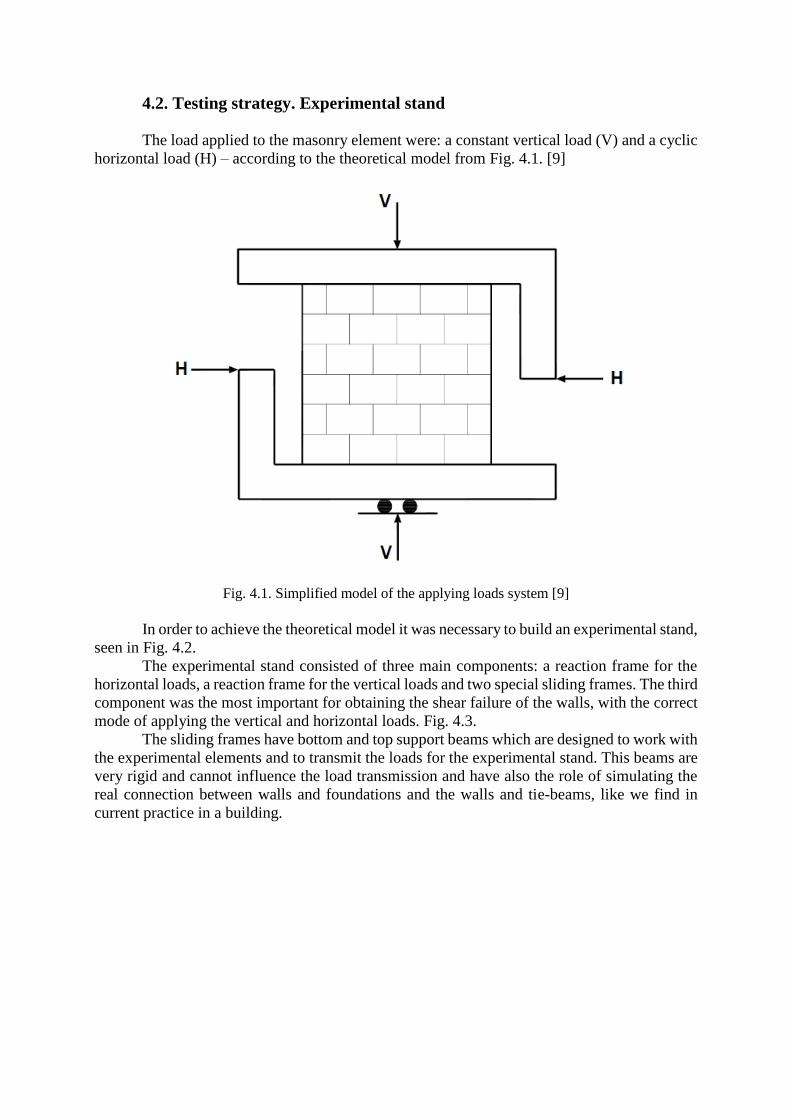
4.2. Testing strategy. Experimental stand
The load applied to the masonry element were: a constant vertical load (V) and a cyclic
horizontal load (H) – according to the theoretical model from Fig. 4.1. [9]
Fig. 4.1. Simplified model of the applying loads system [9]
In order to achieve the theoretical model it was necessary to build an experimental stand,
seen in Fig. 4.2.
The experimental stand consisted of three main components: a reaction frame for the
horizontal loads, a reaction frame for the vertical loads and two special sliding frames. The third
component was the most important for obtaining the shear failure of the walls, with the correct
mode of applying the vertical and horizontal loads. Fig. 4.3.
The sliding frames have bottom and top support beams which are designed to work with
the experimental elements and to transmit the loads for the experimental stand. This beams are
very rigid and cannot influence the load transmission and have also the role of simulating the
real connection between walls and foundations and the walls and tie-beams, like we find in
current practice in a building.
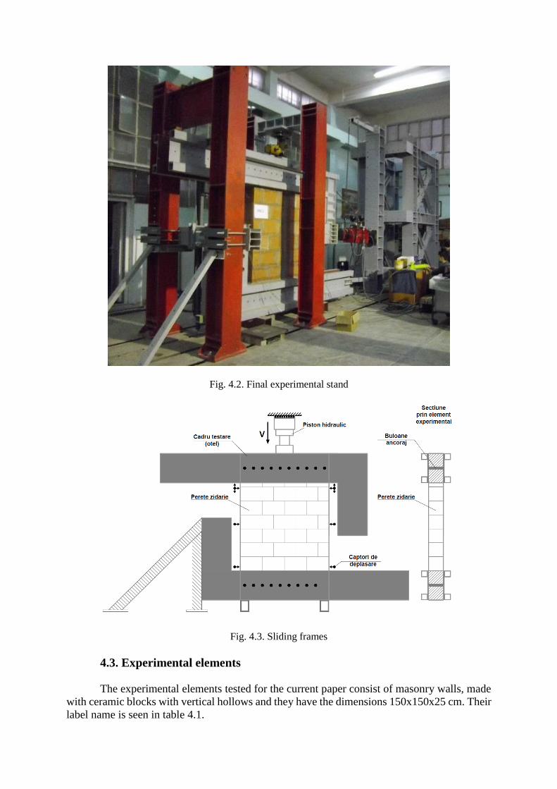
Fig. 4.2. Final experimental stand
Fig. 4.3. Sliding frames
4.3. Experimental elements
The experimental elements tested for the current paper consist of masonry walls, made
with ceramic blocks with vertical hollows and they have the dimensions 150x150x25 cm. Their
label name is seen in table 4.1.
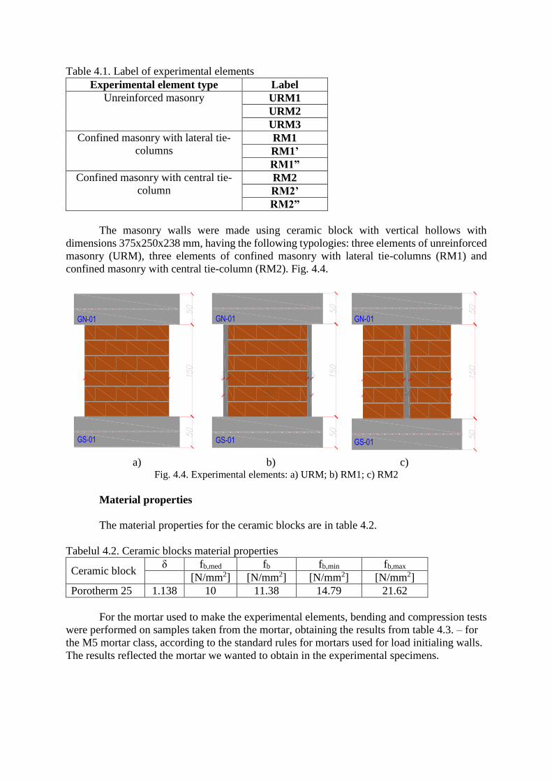
Table 4.1. Label of experimental elements
Experimental element type Label
Unreinforced masonry URM1
URM2
URM3
Confined masonry with lateral tie-
columns RM1
RM1’
RM1”
Confined masonry with central tie-
column RM2
RM2’
RM2”
The masonry walls were made using ceramic block with vertical hollows with
dimensions 375x250x238 mm, having the following typologies: three elements of unreinforced
masonry (URM), three elements of confined masonry with lateral tie-columns (RM1) and
confined masonry with central tie-column (RM2). Fig. 4.4.
GN-01
GS-01
GN-01
GS-01
GN-01
GS-01
a) b) c)
Fig. 4.4. Experimental elements: a) URM; b) RM1; c) RM2
Material properties
The material properties for the ceramic blocks are in table 4.2.
Tabelul 4.2. Ceramic blocks material properties
Ceramic block δ fb,med fb fb,min fb,max
[N/mm2] [N/mm2] [N/mm2] [N/mm2]
Porotherm 25 1.138 10 11.38 14.79 21.62
For the mortar used to make the experimental elements, bending and compression tests
were performed on samples taken from the mortar, obtaining the results from table 4.3. – for
the M5 mortar class, according to the standard rules for mortars used for load initialing walls.
The results reflected the mortar we wanted to obtain in the experimental specimens.
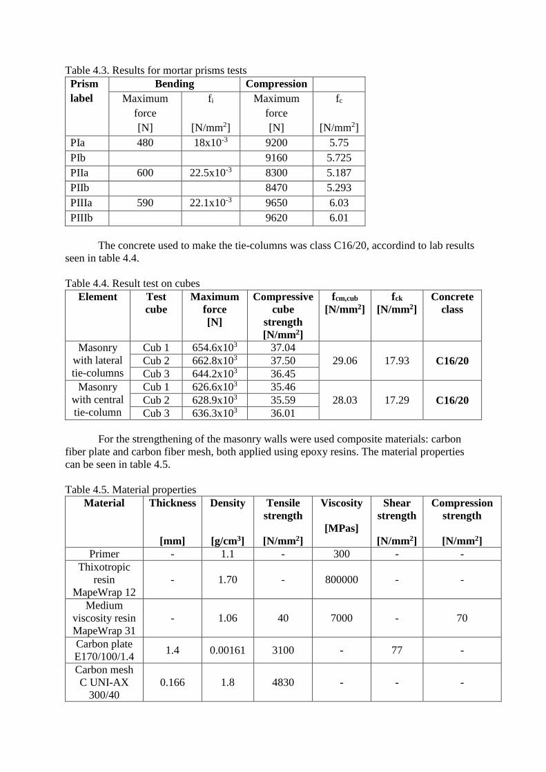
Table 4.3. Results for mortar prisms tests
Prism
label
Bending Compression
Maximum
force
[N]
fi
[N/mm2]
Maximum
force
[N]
fc
[N/mm2]
PIa 480 18x10-3 9200 5.75
PIb 9160 5.725
PIIa 600 22.5x10⁻³ 8300 5.187
PIIb 8470 5.293
PIIIa 590 22.1x10⁻³ 9650 6.03
PIIIb 9620 6.01
The concrete used to make the tie-columns was class C16/20, accordind to lab results
seen in table 4.4.
Table 4.4. Result test on cubes
Element Test
cube
Maximum
force
[N]
Compressive
cube
strength
[N/mm2]
fcm,cub
[N/mm2]
fck
[N/mm2]
Concrete
class
Masonry
with lateral
tie-columns
Cub 1 654.6x10³ 37.04
29.06 17.93 C16/20 Cub 2 662.8x10³ 37.50
Cub 3 644.2x10³ 36.45
Masonry
with central
tie-column
Cub 1 626.6x10³ 35.46
28.03 17.29 C16/20 Cub 2 628.9x10³ 35.59
Cub 3 636.3x10³ 36.01
For the strengthening of the masonry walls were used composite materials: carbon
fiber plate and carbon fiber mesh, both applied using epoxy resins. The material properties
can be seen in table 4.5.
Table 4.5. Material properties
Material Thickness
[mm]
Density
[g/cm3]
Tensile
strength
[N/mm2]
Viscosity
[MPas]
Shear
strength
[N/mm2]
Compression
strength
[N/mm2]
Primer - 1.1 - 300 - -
Thixotropic
resin
MapeWrap 12
- 1.70 - 800000 - -
Medium
viscosity resin
MapeWrap 31
- 1.06 40 7000 - 70
Carbon plate
E170/100/1.4 1.4 0.00161 3100 - 77 -
Carbon mesh
C UNI-AX
300/40
0.166 1.8 4830 - - -
4.4. Strengthening of the experimental elements
The second part of the experimental program consisted in the consolidation of
damaged masonry walls using polymeric composite materials. The strengthening solution
consisted in applying the composite materials to the main diagonals of the elements, on both
sides, where the important damages were produced. The first element of unreinforced
masonry was strengthened using carbon plate and the other eight elements were strengthened
using carbon mesh. This decision was made because of the fragile failure of the first element.
The carbon mesh MapeWrap C UNI-AX is a uni-directional mesh with high elasticity
modulus and high tensile strength.
The application of the carbon mesh was made following these steps:
- cleaning the wall surface by removing mortar traces and masonry pieces, from the
damages of the walls in the first tests;
- application of MapeWrap Primer for a better adhesion of the resin layer – application
is made with a brush, only in the areas where the resin is to be applied;
- application fo MapeWrap 12 epoxy resin to smooth unevenness and seal the porous
surfaces – application is made in a 2 mm layer for a better leveling;
- application of the first layer of MapeWrap 31 with a brush in a 0.5 mm thickness
layer, followed immediatly by the carbon mesh and leveling with a rubber roll. In the
end for the impregnation of the carbon mesh, we applied a second layer of MapeWrap
31 resin with a brush.
Between the application of different layers was expected at least 24 hours. After the
manual application of resin MapeWrap 12, a mechanical grinding was necessary in order to
smooth the surface, in order to apply to safely apply the carbon mesh.
This procedure was used for all the experimental elements on both sides of the walls,
after they suffered damage from the inital tests.
4.5. Loading protocol
The cyclic horizontal loads were applied using an actuator that was able to perform
cycles movements and the cycles were performed according to Fig. 4.5.
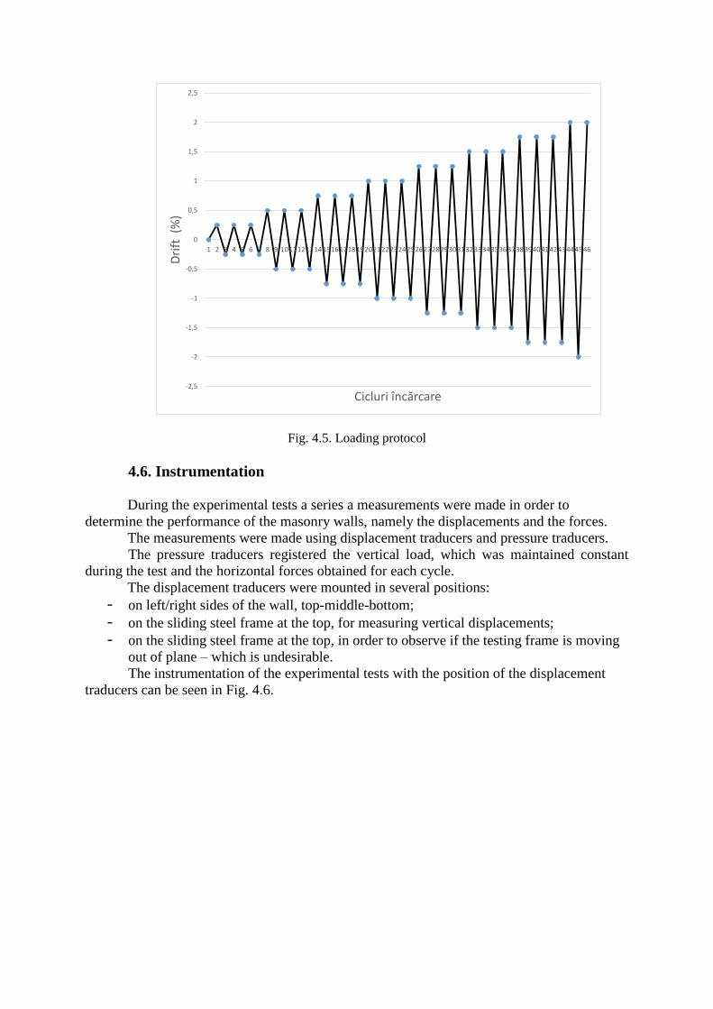
Fig. 4.5. Loading protocol
4.6. Instrumentation
During the experimental tests a series a measurements were made in order to
determine the performance of the masonry walls, namely the displacements and the forces.
The measurements were made using displacement traducers and pressure traducers.
The pressure traducers registered the vertical load, which was maintained constant
during the test and the horizontal forces obtained for each cycle.
The displacement traducers were mounted in several positions:
- on left/right sides of the wall, top-middle-bottom;
- on the sliding steel frame at the top, for measuring vertical displacements;
- on the sliding steel frame at the top, in order to observe if the testing frame is moving
out of plane – which is undesirable.
The instrumentation of the experimental tests with the position of the displacement
traducers can be seen in Fig. 4.6.
-2,5
-2
-1,5
-1
-0,5
0
0,5
1
1,5
2
2,5
1 2 3 4 5 6 7 8 9 10111213141516171819202122232425262728293031323334353637383940414243444546
Dri
ft (
%)
Cicluri încărcare
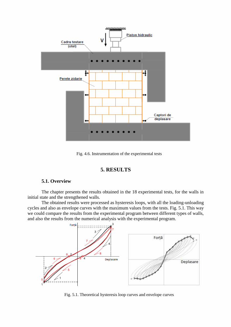
Fig. 4.6. Instrumentation of the experimental tests
5. RESULTS
5.1. Overview
The chapter presents the results obtained in the 18 experimental tests, for the walls in
initial state and the strengthened walls.
The obtained results were processed as hysteresis loops, with all the loading-unloading
cycles and also as envelope curves with the maximum values from the tests. Fig. 5.1. This way
we could compare the results from the experimental program between different types of walls,
and also the results from the numerical analysis with the experimental program.
Fig. 5.1. Theoretical hysteresis loop curves and envelope curves
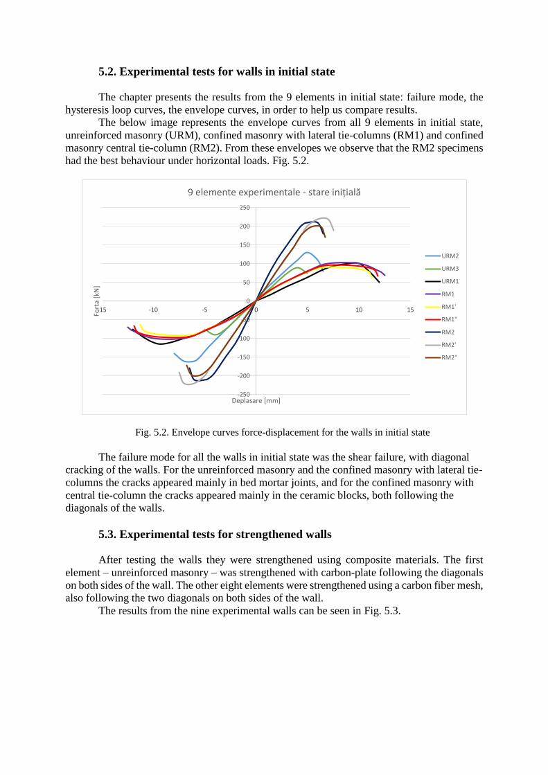
5.2. Experimental tests for walls in initial state
The chapter presents the results from the 9 elements in initial state: failure mode, the
hysteresis loop curves, the envelope curves, in order to help us compare results.
The below image represents the envelope curves from all 9 elements in initial state,
unreinforced masonry (URM), confined masonry with lateral tie-columns (RM1) and confined
masonry central tie-column (RM2). From these envelopes we observe that the RM2 specimens
had the best behaviour under horizontal loads. Fig. 5.2.
Fig. 5.2. Envelope curves force-displacement for the walls in initial state
The failure mode for all the walls in initial state was the shear failure, with diagonal
cracking of the walls. For the unreinforced masonry and the confined masonry with lateral tie-
columns the cracks appeared mainly in bed mortar joints, and for the confined masonry with
central tie-column the cracks appeared mainly in the ceramic blocks, both following the
diagonals of the walls.
5.3. Experimental tests for strengthened walls
After testing the walls they were strengthened using composite materials. The first
element – unreinforced masonry – was strengthened with carbon-plate following the diagonals
on both sides of the wall. The other eight elements were strengthened using a carbon fiber mesh,
also following the two diagonals on both sides of the wall.
The results from the nine experimental walls can be seen in Fig. 5.3.
-250
-200
-150
-100
-50
0
50
100
150
200
250
-15 -10 -5 0 5 10 15
Fort
a [k
N]
Deplasare [mm]
9 elemente experimentale - stare inițială
URM2
URM3
URM1
RM1
RM1'
RM1"
RM2
RM2'
RM2"
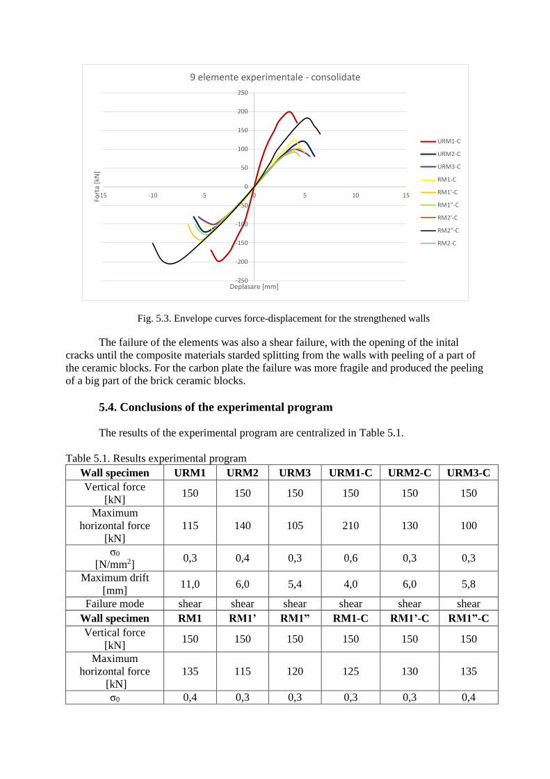
Fig. 5.3. Envelope curves force-displacement for the strengthened walls
The failure of the elements was also a shear failure, with the opening of the inital
cracks until the composite materials starded splitting from the walls with peeling of a part of
the ceramic blocks. For the carbon plate the failure was more fragile and produced the peeling
of a big part of the brick ceramic blocks.
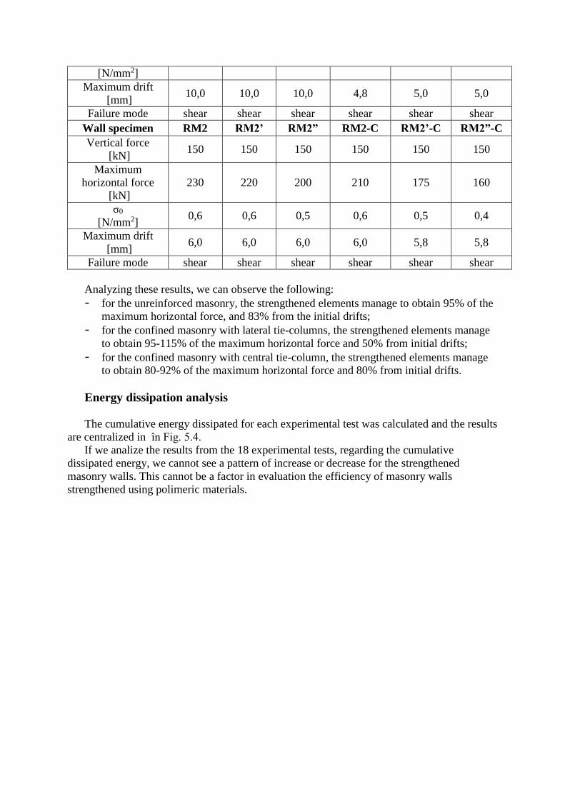
5.4. Conclusions of the experimental program
The results of the experimental program are centralized in Table 5.1.
Table 5.1. Results experimental program
Wall specimen URM1 URM2 URM3 URM1-C URM2-C URM3-C
Vertical force
[kN] 150 150 150 150 150 150
Maximum
horizontal force
[kN]
115 140 105 210 130 100
σ0
[N/mm2] 0,3 0,4 0,3 0,6 0,3 0,3
Maximum drift
[mm] 11,0 6,0 5,4 4,0 6,0 5,8
Failure mode shear shear shear shear shear shear
Wall specimen RM1 RM1’ RM1” RM1-C RM1’-C RM1”-C
Vertical force
[kN] 150 150 150 150 150 150
Maximum
horizontal force
[kN]
135 115 120 125 130 135
σ0 0,4 0,3 0,3 0,3 0,3 0,4
-250
-200
-150
-100
-50
0
50
100
150
200
250
-15 -10 -5 0 5 10 15
Fort
a [k
N]
Deplasare [mm]
9 elemente experimentale - consolidate
URM1-C
URM2-C
URM3-C
RM1-C
RM1'-C
RM1"-C
RM2'-C
RM2"-C
RM2-C
[N/mm2]
Maximum drift
[mm] 10,0 10,0 10,0 4,8 5,0 5,0
Failure mode shear shear shear shear shear shear
Wall specimen RM2 RM2’ RM2” RM2-C RM2’-C RM2”-C
Vertical force
[kN] 150 150 150 150 150 150
Maximum
horizontal force
[kN]
230 220 200 210 175 160
σ0
[N/mm2] 0,6 0,6 0,5 0,6 0,5 0,4
Maximum drift
[mm] 6,0 6,0 6,0 6,0 5,8 5,8
Failure mode shear shear shear shear shear shear
Analyzing these results, we can observe the following:
- for the unreinforced masonry, the strengthened elements manage to obtain 95% of the
maximum horizontal force, and 83% from the initial drifts;
- for the confined masonry with lateral tie-columns, the strengthened elements manage
to obtain 95-115% of the maximum horizontal force and 50% from initial drifts;
- for the confined masonry with central tie-column, the strengthened elements manage
to obtain 80-92% of the maximum horizontal force and 80% from initial drifts.
Energy dissipation analysis
The cumulative energy dissipated for each experimental test was calculated and the results
are centralized in în Fig. 5.4.
If we analize the results from the 18 experimental tests, regarding the cumulative
dissipated energy, we cannot see a pattern of increase or decrease for the strengthened
masonry walls. This cannot be a factor in evaluation the efficiency of masonry walls
strengthened using polimeric materials.
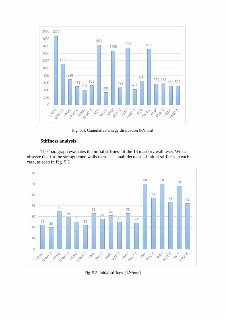
Fig. 5.4. Cumulative energy dissipation [kNmm]
Stiffness analysis
This paragraph evaluates the initial stiffness of the 18 masonry wall tests. We can
observe that for the strengthened walls there is a small decrease of initial stiffness in each
case, as seen in Fig. 5.5.
Fig. 5.5. Initial stiffness [kN/mm]
2220
35
2925
22
33
2831
25
33
24
60
47
60
43
58
42
0
10
20
30
40
50
60
70
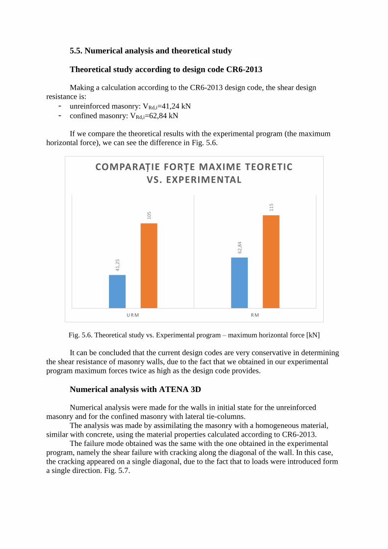
5.5. Numerical analysis and theoretical study
Theoretical study according to design code CR6-2013
Making a calculation according to the CR6-2013 design code, the shear design
resistance is:
- unreinforced masonry: VRd,i=41,24 kN
- confined masonry: VRd,i=62,84 kN
If we compare the theoretical results with the experimental program (the maximum
horizontal force), we can see the difference in Fig. 5.6.
Fig. 5.6. Theoretical study vs. Experimental program – maximum horizontal force [kN]
It can be concluded that the current design codes are very conservative in determining
the shear resistance of masonry walls, due to the fact that we obtained in our experimental
program maximum forces twice as high as the design code provides.
Numerical analysis with ATENA 3D
Numerical analysis were made for the walls in initial state for the unreinforced
masonry and for the confined masonry with lateral tie-columns.
The analysis was made by assimilating the masonry with a homogeneous material,
similar with concrete, using the material properties calculated according to CR6-2013.
The failure mode obtained was the same with the one obtained in the experimental
program, namely the shear failure with cracking along the diagonal of the wall. In this case,
the cracking appeared on a single diagonal, due to the fact that to loads were introduced form
a single direction. Fig. 5.7.
41
,25
62
,84
10
5
11
5
U R M R M
COMPARAȚIE FORȚE MAXIME TEORETIC VS. EXPERIMENTAL
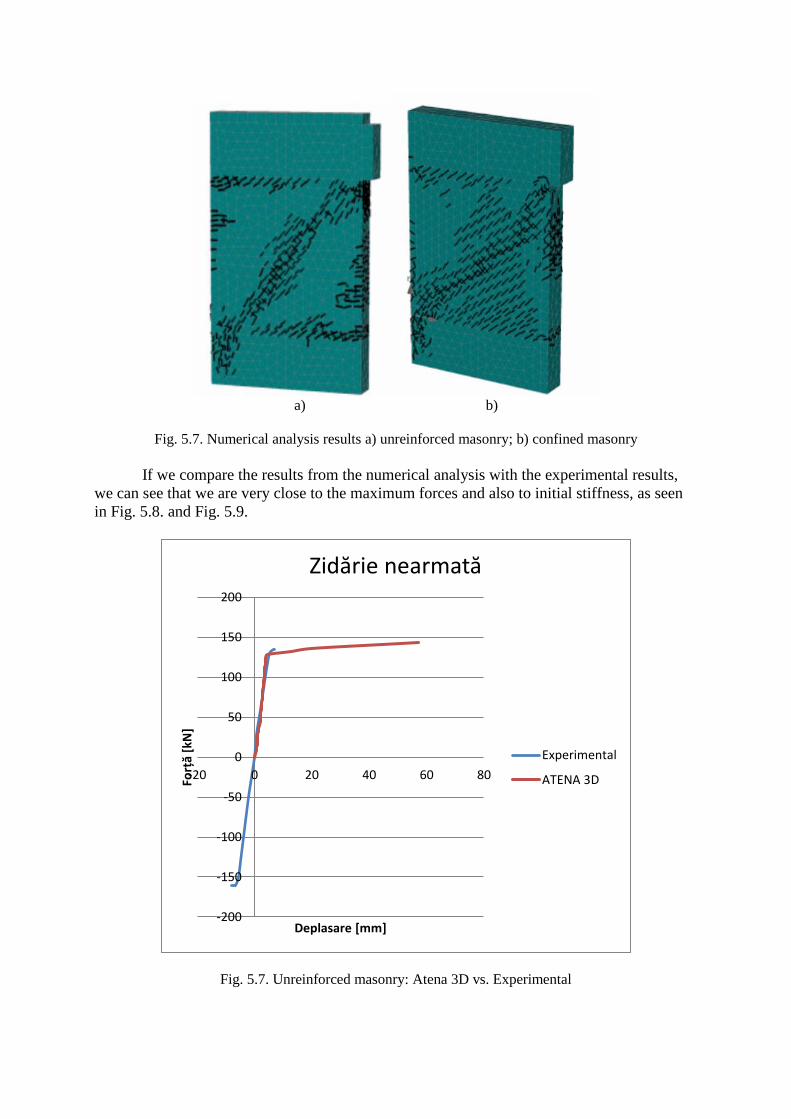
a) b)
Fig. 5.7. Numerical analysis results a) unreinforced masonry; b) confined masonry
If we compare the results from the numerical analysis with the experimental results,
we can see that we are very close to the maximum forces and also to initial stiffness, as seen
in Fig. 5.8. and Fig. 5.9.
Fig. 5.7. Unreinforced masonry: Atena 3D vs. Experimental
-200
-150
-100
-50
0
50
100
150
200
-20 0 20 40 60 80
Forț
ă[k
N]
Deplasare [mm]
Zidărie nearmată
Experimental
ATENA 3D
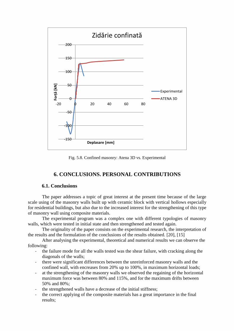
Fig. 5.8. Confined masonry: Atena 3D vs. Experimental
6. CONCLUSIONS. PERSONAL CONTRIBUTIONS
6.1. Conclusions
The paper addresses a topic of great interest at the present time because of the large
scale using of the masonry walls built up with ceramic block with vertical hollows especially
for residential buildings, but also due to the increased interest for the strengthening of this type
of masonry wall using composite materials.
The experimental program was a complex one with different typologies of masonry
walls, which were tested in initial state and then strengthened and tested again.
The originality of the paper consists on the experimental research, the interpretation of
the results and the formulation of the conclusions of the results obtained. [20], [15]
After analysing the experimental, theoretical and numerical results we can observe the
following:
- the failure mode for all the walls tested was the shear failure, with cracking along the
diagonals of the walls;
- there were significant differences between the unreinforced masonry walls and the
confined wall, with encreases from 20% up to 100%, in maximum horizontal loads;
- at the strengthening of the masonry walls we observed the regaining of the horizontal
maximum force was between 80% and 115%, and for the maximum drifts between
50% and 80%;
- the strengthened walls have a decrease of the initial stiffness;
- the correct applying of the composite materials has a great importance in the final
results;
-150
-100
-50
0
50
100
150
200
-20 0 20 40 60 80
Forț
ă[k
N]
Deplasare [mm]
Zidărie confinată
Experimental
ATENA 3D
- the theoretical study shows that the design codes are very conservative, due to the
difference between our experimental program and the theoretical values obtained;
- the numerical analysis can be very useful in assesing the maximum capacity of the
walls in initial state.
6.2. Personal contributions
Personal contributions are the following:
- extended bibliographic study on the behaviour of masonry walls subjected to seismic
actions, and also masonry walls strengthened using composite materials;
- conceiving and participation in the realization of the experimental stand in the Civil
Engineering Laboratory;
- designing an experimental test program that presents innovative features;
- conducting experimental test on 9 masonry walls;
- designing strengthening methods for the experimental elements and testing the 9 walls
after their strengthening;
- analysis of the results obtained, compared with the results from numerical and
theoretical studies made by the author.
7. CASE STUDY. PRACTICAL APPLICATION
Overview
- Rezidential building P+2E
- Storey level: het=3,00 m
- Maximum building dimensions: 12,40 x 12,45 m
- Built area: 134,70 mp
- Confined masonry structural system and horizontal reinforcements if necessary
- Interior and exterior walls made with Porotherm 30 and Porotherm 25 ceramic blocks
- Location: Timișoara, ag=0,20g, Tc=0,7s.
- Geometry of the structure can be observed in Fig. 7.1.
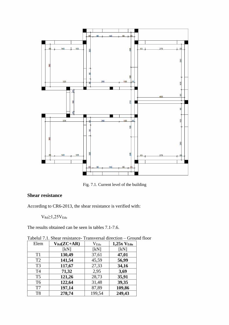
Fig. 7.1. Current level of the building
Shear resistance
According to CR6-2013, the shear resistance is verified with:
VRd≥1,25VEdu
The results obtained can be seen în tables 7.1-7.6.
Tabelul 7.1. Shear resistance- Transversal direction – Ground floor
Elem VRd(ZC+AR) VEdu 1,25x VEdu
[kN] [kN] [kN]
T1 130,49 37,61 47,01
T2 141,54 45,59 56,99
T3 117,67 27,33 34,16
T4 71,32 2,95 3,69
T5 121,26 28,73 35,91
T6 122,64 31,48 39,35
T7 197,14 87,89 109,86
T8 278,74 199,54 249,43
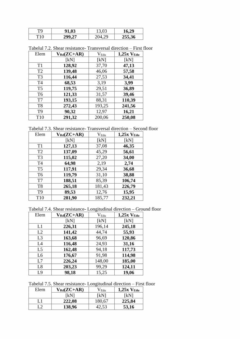
T9 91,03 13,03 16,29
T10 299,27 204,29 255,36
Tabelul 7.2. Shear resistance- Transversal direction – First floor
Elem VRd(ZC+AR) VEdu 1,25x VEdu
[kN] [kN] [kN]
T1 128,92 37,70 47,13
T2 139,48 46,06 57,58
T3 116,44 27,53 34,41
T4 68,53 3,19 3,99
T5 119,75 29,51 36,89
T6 121,33 31,57 39,46
T7 193,15 88,31 110,39
T8 272,43 193,25 241,56
T9 90,32 12,97 16,21
T10 291,32 200,06 250,08
Tabelul 7.3. Shear resistance- Transversal direction – Second floor
Elem VRd(ZC+AR) VEdu 1,25x VEdu
[kN] [kN] [kN]
T1 127,13 37,08 46,35
T2 137,09 45,29 56,61
T3 115,02 27,20 34,00
T4 64,98 2,19 2,74
T5 117,91 29,34 36,68
T6 119,79 31,10 38,88
T7 188,51 85,39 106,74
T8 265,18 181,43 226,79
T9 89,53 12,76 15,95
T10 281,90 185,77 232,21
Tabelul 7.4. Shear resistance- Longitudinal direction – Ground floor
Elem VRd(ZC+AR) VEdu 1,25x VEdu
[kN] [kN] [kN]
L1 226,31 196,14 245,18
L2 141,42 44,74 55,93
L3 163,68 96,69 120,86
L4 116,48 24,93 31,16
L5 162,48 94,18 117,73
L6 176,67 91,98 114,98
L7 226,24 148,00 185,00
L8 203,23 99,29 124,11
L9 98,18 15,25 19,06
Tabelul 7.5. Shear resistance- Longitudinal direction – First floor
Elem VRd(ZC+AR) VEdu 1,25x VEdu
[kN] [kN] [kN]
L1 222,08 180,67 225,84
L2 138,96 42,53 53,16
L3 161,33 92,58 115,73
L4 114,97 24,20 30,25
L5 159,77 89,95 112,44
L6 173,29 84,96 106,20
L7 220,82 136,55 170,69
L8 197,81 93,06 116,33
L9 97,52 14,95 18,69
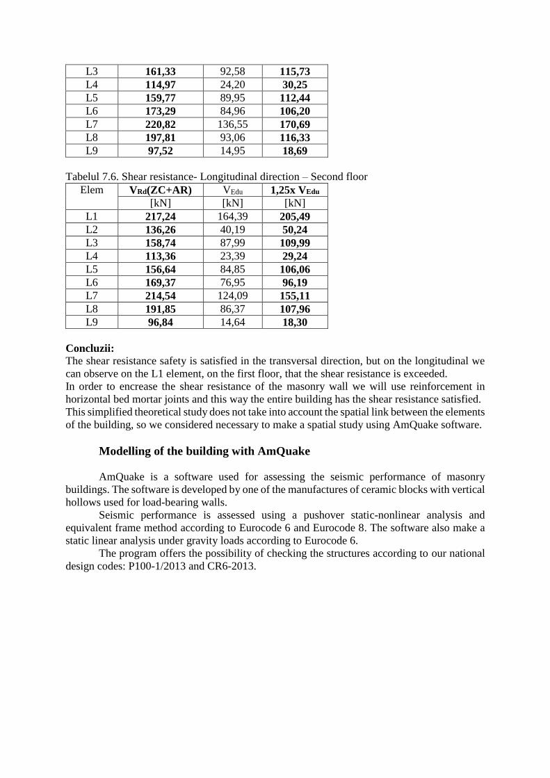
Tabelul 7.6. Shear resistance- Longitudinal direction – Second floor
Elem VRd(ZC+AR) VEdu 1,25x VEdu
[kN] [kN] [kN]
L1 217,24 164,39 205,49
L2 136,26 40,19 50,24
L3 158,74 87,99 109,99
L4 113,36 23,39 29,24
L5 156,64 84,85 106,06
L6 169,37 76,95 96,19
L7 214,54 124,09 155,11
L8 191,85 86,37 107,96
L9 96,84 14,64 18,30
Concluzii:
The shear resistance safety is satisfied in the transversal direction, but on the longitudinal we
can observe on the L1 element, on the first floor, that the shear resistance is exceeded.
In order to encrease the shear resistance of the masonry wall we will use reinforcement in
horizontal bed mortar joints and this way the entire building has the shear resistance satisfied.
This simplified theoretical study does not take into account the spatial link between the elements
of the building, so we considered necessary to make a spatial study using AmQuake software.
Modelling of the building with AmQuake
AmQuake is a software used for assessing the seismic performance of masonry
buildings. The software is developed by one of the manufactures of ceramic blocks with vertical
hollows used for load-bearing walls.
Seismic performance is assessed using a pushover static-nonlinear analysis and
equivalent frame method according to Eurocode 6 and Eurocode 8. The software also make a
static linear analysis under gravity loads according to Eurocode 6.
The program offers the possibility of checking the structures according to our national
design codes: P100-1/2013 and CR6-2013.
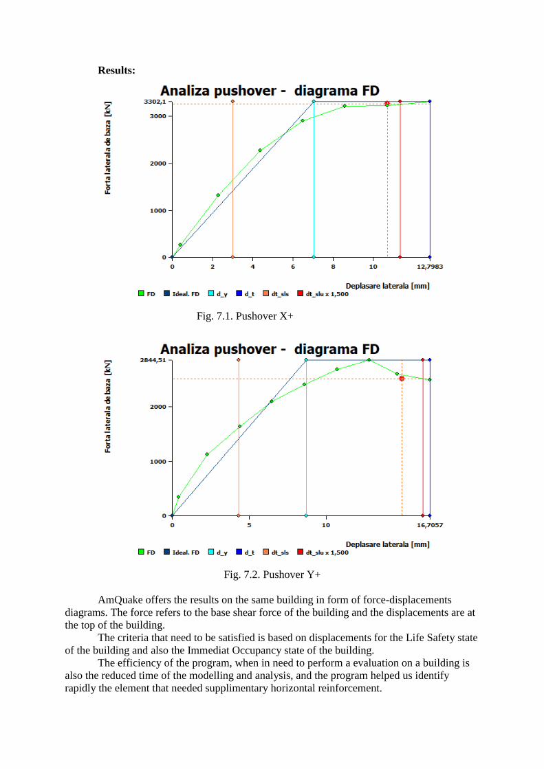
Results:
Fig. 7.1. Pushover X+
Fig. 7.2. Pushover Y+
AmQuake offers the results on the same building in form of force-displacements
diagrams. The force refers to the base shear force of the building and the displacements are at
the top of the building.
The criteria that need to be satisfied is based on displacements for the Life Safety state
of the building and also the Immediat Occupancy state of the building.
The efficiency of the program, when in need to perform a evaluation on a building is
also the reduced time of the modelling and analysis, and the program helped us identify
rapidly the element that needed supplimentary horizontal reinforcement.
Also, there is taked into account the spatial behaviour of the building, compared to the
theoretical study.
In some cases, the design code has made mandatory this type of analysis, due to the
complexity of some buildings geometry.
BIBLIOGRAPHY
[1] CR6-2013 – Cod de proiectare pentru structuri din zidărie.
[2] P100-1/2013 – Cod de proiectare seismică, Partea I – Prevederi de proiectare pentru
clădiri. Capitolul 3 – Acțiunea seismică.
[3] P100-1/2013 – Cod de proiectare seismică, Partea I – Prevederi de proiectare pentru
clădiri. Capitolul 8 – Prevederi specifice construcțiilor din zidărie.
[4] Cretu D., Demetriu S. – Metode pentru calculul răspunsului seismic în codurile
românești de proiectare. Comparații și comentarii. Revista AICPS, pg. 1-9, 2006.
[5] Anastasecu D. – Aspecte ale evoluției reglementărilor tehnice privind protecția
antiseismică a construcțiilor din Municipiul Timișoara. Buletinul AGIR nr. 3/2012.
[6] Mărgărit R. – Contribuții privind concepția, calculul și execuția sistemelor structurale
cu pereți realizați din blocuri ceramice cu goluri verticale, în zone seismice. Teză de
doctorat. UTCB, București, 2011.
[7] Petersen R. – In-plane shear behavior of unreinforced masonry panels strengthened with
fibre reinforced polymer strips, The University of Newcastle, Australia, 2009.
[8] Dogariu A. – Seismic retrofitting techniques based on metallic materials of RC and/or
masonry buildings. PhD Thesis. Editura Universitatea “Politehnica” Timișoara, 2009.
[9] Nagy-Gyorgy T. – Materiale compozite polimerice pentru consolidarea elementelor din
zidărie și beton. Editura Politehnica. Timișoara 2007.
[10] Babatunde S.A. – Review of strengthening techniques for masonry using fibre
reinforced polymers. Composite Structures 161, pg. 246-255, 2017.
[11] Dăescu C. – Reabilitarea elementelor de construcție utilizând materiale compozite
polimerice. Teză doctorat. Editura Universitatea “Politehnica” Timișoara, 2011.
[12] Niste M.S. – Contribuții privind tehnologia de realizare, reparare și consolidare a
construcțiilor civile cu structura din zidărie amplasate în zone seismice. Teză doctorat.
2015.
[13] Fabian A.A. – Study on the performances of composite steel concrete
structural shear walls under lateral loads. Teză doctorat. Universitatea Politehnica
Timișoara 2012.
[14] Fofiu M. – Retrofitting the precast RC walls panels using externally bonded CFRP
laminates. Teză doctorat. Universitatea Politehnica Timisoara 2017.
[15] Demeter I. – Seismic retrofit of precast RC walls by externally bonded CFRP
composites. Teză doctorat. Universitatea Politehnica Timisoara 2011.
[16] Matei C.L. – Contribuții asupra definirii caracteristicilor de rezistență și deformabilitate
ale zidăriei utilizate în zone seismice. Teză doctorat. UTCB. 2013.
[17] Laurenco P.B. - Experimental and numerical issues in the modelling of the mechanical
behaviour of masonry. Structural Analysis of Historical Constructions II, University of
Minho, Barcelona 1998.
[18] Petersen R. – In-plane shear behavior of unreinforced masonry panels strengthened with
fibre reinforced polymer strips, The University of Newcastle, Australia, 2009.
[19] Moșoarcă M. – Contribuții la calculul și alcătuirea pereților structurali din
beton armat. Teză doctorat. Universitatea Politehnica Timișoara 2003.
[20] da Porto F., Mosele F., Modena C. – In-plane cyclic behaviour of a new reinforced
masonry system: Experimental results. Engineering Structures 33, pg. 2584-2596, 2011.