Embed Size (px)
Citation preview
AD-RlM 149 A DEFINITION STUDY FOR INPROVING INYENTORY CONTROL AND 1/1ANDWLING FOR THE 0. (U) SOUTHWEST RESEARCH INST SON
'ttSI FE ANTONIO TX 21 FEB 00 F41608-96-C-AS FO153 W

6 L .
(I'll
ILL
iIII 2 11011.
MlrnCOPY RcS ~IUlT N TEST CHAR
I)S 1963-
q w w lp q wI w lw w w w w V V V V *
SOUTHWEST RESEARCH INSTITUTE
Post Office Drawer 28510, 6220 Culebra Road
San Antonio, Texas 78284
1-- A DEFINITION STUDY FOR IMPROVING00 INVENTORY CONTROL AND HANDLING
FOR THE OVERHAUL FACILITY INBUILDING 329 AT SA-ALC/MAT
FINAL REPORT DTIC'CDRL No. 2 ELECTE
JUL 0 6 IM8Contract No. F41608-86-C-A016 S ad DEO
SwRl Project No. 14-8917
Prepared for:
United States Air ForceAir Force Logistics Command
San Antonio Air Logistics CenterTechnology Repair Division (MAT)
Kelly AFB, Texas 78241
Prepared by:
Automation and Data Systems DepartmentSouthwest Research InstituteLDLSRIBurm sTATEMENT Al
Approved for public releel | February 21, 1986., Distribution Unlimited
MA E OR
Approved by:
Richard B. Curtin, Director
Automation and Data Systems Department
%-3f /A.'

PREFACE
Southwest Research Institute (SwRI) is pleased to submit this finalreport covering the reporting period of October 31, 1985 to January 31,1986 in support of contract no. F41608-86-C-A016. Receipt of this finalreport satisfies item two of the Contract Data Requirements List (CDRL
No. 2) of the stated contract.
The contents of the report summarize the efforts of the SwRI pr'ejectteam to investigate and collect information pertaining to the control andhandling of inventory within the Building 329 (B329) overhaul facility atKelly AFB, TX. The major focus of the work centers on the development ofa functional definition of a system that improves the handling, tracking.storage and scheduling of material throughout the overhaul process. Theexpected benefits of such an effort are the increased accuracy ofproduction scheduling, the reduction of work in process (WIP) andincreased visibility and accountability of inventory in storage.
This final reporL examines the observations and documents collectedduring the reporting period, proposes some initial ideas toward aconceptual system design and evaluates the impact of various designalternatives.
The SwRI project team would like to express its gratitude to allKelly AFB personnel who provided their time and shared their experiences.Their information and insight into the workings of the industrialoverhaul process within the depot proved to be invaluable.
C-TICS i- C) P Fo--g
NTf C-Lt&,
tDi't | ;, ,
,-- --- --'-- -,- . .,d ! .
1W£' Lmk"l I 1<: 1,.,10 ;!
SUMMARY
Analysis of the B329 inventory control and handling procedures revealedthat significant benefits could be gained through the use of computercontrolled mechanized storage equipment to organize and control partsstorage functions, combined with an effective parts tracking system tomonitor the movement of parts between facilities.)
The i R project team conducted a number of personal interviews withvarious MAT shop personnel in order to gain an understanding of materialrouting procedures and functional duties associated with the B329overhaul process. BEeing informed that the present parts pool locationwas to be relocated into a new area that was 30 % smaller, the team 'wastasked with conducting a functional definition of an inventory controland parts storhge system for the new area.-
In addition, the team investigated the requirement of a parts tracking
system that- would mi6nitor the movement of materials within/and betweenthe B329 facility. This required further evaluation into the existingpart identification methods and procedures being used within the shopenvironment. Documents attached to parts take the form of embossed metaltags, paper work control documents and soon will also include laseretched metal tags for the new dimensional inspection system. (k -- )
The conclusions of the definition study efforts stated that the futuresite of the parts pool would adequately provide the necessary volumetricstorage capacity using horizontal carousel storage equipment.Recommendations were made to employ the use of a high powered mini-computer to perform the function of carousel control, inventory controland decision analysis utilities.
Pertaining to the tracking system, the team recommended that the existingMaintenance Job Tracking (MJT) system can be utilized, providing thefollowing changes and conditions are incorporated; stabilization ofsystem access priority, utilization of portable data collection units andimproved support of the systems branch to provide adequate systemsservices for the users.

TABLE OF CONTENTS
Page
PREFACE...............................i
SUMMARY . . . . . . . . . . . . . . . . . . . . . . . . . . . i *
LIST OF ILLUSTRATIONS ....................... iv
1.0 INTRODUCTION . ........................ 1
1.1 Backround...... ............. .. ........ 11.2 Scope of Work. ..................... 21.3 SwRI Program Structure .. ................ 21.4 Project Milestones .. .................. 3
2.0 SUBJECT REVIEW.................. . . . ... .. .. . . ....
2.1 Material Flow. ..................... 62.2 Parts Identification. .................. 162.3 Parts Pool Storage. ................... 212.4 Material Control System. ............... 382.5 Computer Control System. ............... 49
3.0 CONCLUSIONS. ......................... 51
4.0 RECOMMENDATIONS. ....................... 53
APPENDIXES. ............................ 56
A Project Contact Sheet ................... 57B Initial Survey Checklist. ................. 58C Documents Received. .................... 6iD Work Control Documents. .................. 68E Bldg 329 Systems Implementation Plan .. ......... 72F Parts Pool Layout Drawings. ................ 73
ABBREVIATIONS ........................... 81
WIK LMVIRii
.s.aa~na~anL~fwLwVENd HIIUUMNAn Wi an NI~ Awn An .- - -
LIST OF ILLUSTRATIONS
Figure Pg
1 B329 Present Shop Layout .................. 72 Parts Flow Diagram - Simplified .. ............ 63 Metal Tag Format. .................... 164 Proposed Laser Tag Format .. ............... 20*-5 B329 Parts Pool Locations .. ............... 216 Parts Pool Layout - Present. ............... 227 Parts Pool Shelf Indexing Method ............. 238 Parts Pool Area - Future. ................ 27
* 9 Proposed Carousel W~ork Station Layout...........3710 Computer System Block Diagram. .............. 44
*Table
1 Model Numibers Overhauled in Building 329. ........ 12 Building 329 In-Process Buffer Sizes ........... 13
* 3 W~ork Control Document Format ............... 174 WCD Color Coding Scheme - B329. ............. 185 B329 Parts Pool Throughput Capacity. ........... 266 Parts Pool Room Attribute Comparisons. .......... 337 Storage Equipment Configuration Chart. .......... 348 Layout Volumetric Comparisons .. ............. 359 MJT Data Collection Stations. .............. 39
Drawing
SK-008 Parts Flow Diagram - Expanded .. ............. 9SK-001 Parts Pool Layout No. I .. ................ 74SK-002 Parts Pool Layout No. 2 .. ................ 75SK-003 Parts Pool Layout No. 3 .. ................ 76SK-004 Parts Pool Layout No. 4 .. ................ 77SK-005 Parts Pool Layout No. 5 .. ................ 78SK-006 Parts Pool Layout No. 6 .. ................ 79SK-007 Parts Pool Layout No. 7 .. ................ 80

1.0 INTRODUCTION
The San Antonio Air Logistics Center (SA-ALC) at Kelly AFB, Texas,is one of the largest industrial complexes located in the southwestportion of the United States. SA-ALC, being responsible for providingdepot maintenance and overhaul for some of the nations most sophisticatedaircraft and jet propulsion systems, utilizes various and complexindustrial processes to support the mission of fleet readiness.
An overhaul facility housed in B329 at Kelly AFB is responsible forproviding depot maintenance for 12 models of gas turbine engines (GTEs),17 models of aircraft starters and 4 models of accessory drives, seeTable 1. The facilty is tasked with the production of approximatelv1600 GTEs and 6000 starters per year.
Table 1Model Numbers Overhauled in Building 329
--------------------------------------------------------------
GTE I STARTERS I MISC I+------------+--------------------------+----------------------
36-50 1 100-87 L/H AMAD85-56 1 100-89 R/H AMAD85-70 1 100-97 JFS85-71 1 100-138 CGB85-72 1 100-17685-106 100-176A85-116 100-30285-180 100-32585-180L 100-39585-397 100-421
1 165-1 100-422T41M9 CPS-01
CPS-02-MODCPS-07CPS-09CPS-1ICPS-12
----------------------------------------------------
1.1 Backround
The overhaul process is comprised of a number of sub-procesesstarting with disassembly, cleaning, inspection, repair, manufacturing,assembly and culminating with the dynamic testing of the completed unit.To accomplish the overhaul process, parts are removed, segregated.routed, collected, processed, sorted, stored, kitted and eventuall'."converged to become part of a unit assembly.
i

The maintenance/overhaul environment places stringent requirementson the need to collect and report shop floor information pertaining tothe locations and quantities of material in-process, inventory on-handand estimated flow times for process completion. When accomplished in anaccurate and timely manner this information proves to be invaluable indetermining realistic production schedules.
A survey of the B329 facility and process reveals that the flow ofinformation, tracking of parts and control/handling of inventory isaccomplished in a strictly manual mode. This environment requiresintensive utilization of shop personnel to move and handle material,identify and sort parts and record and maintain paper log (data) sheetsin an effort to provide the information and visibility necessary foreffective production management.
.1.2 Scope of Work
Overall effectiveness of production scheduling is primarily affectedby the timely tracking and status reporting of material in-process,strict control of part inventories, accurate accounting of inventorytransactions and condemnations, efficient parts storage/retrievalmethods, and availability of decision support utilities to assesscontingency plans.
The major thrust of the contract is the development of a functionaldefinition of a system that improves the handling, tracking, storage andscheduling of material throughout the overhaul process within B329. Toaccomplish this, the project team has focused on four separate topicareas:
o Parts Storage o In-Process Parts Trackingo Inventory Control o Decision Support Utilities
It is the scope of this contract to functionally specify theconceptual design of a system to address each of these areas. Theexpected benefits of such a system are the reduction of work in process(WIP) staging buffers, an increased visibility and accountability ofinventory in storage and the development of more accurate productionschedules through the utilization of decision support utilities.
1.3 SwRI Program Structure
Southwest Research Institute (SwRI), an independent, non-profitapplied research and development organization, has established a threelayer organizational structure for the project team, designed to provideoverall leadership and technical support. The three layers consist of:a) Program Manager, b) Project Manager and c) Technical Consultants.
The role of the program manager is to provide overall programguidance, technical direction and contractual monitoring. The projectmanager is tasked with the responsibilities of identifying problem areas.
2
invoking the aid of applicable technical consultants and esr)1 i!hing time/task schedules. As problem areas are defined, the project manager
will confer with the program manager to select appropriate staff members
to fill the roles of technical consultants. The consultants role is to
provide a depth of experience and knowledge to a well focused problem
description. As problems are addressed, the project manager orchestrates
the smooth and orderly integration of potential solutions.
o Program Manager - R. Thompson
oo Project Manager - T. Der Tatevasion
ooo Consultant - Material Storage - L. Poirier
ooo Consultant - Computer-Hard/Software - D. Vickers S
ooo Consultant - Material Handling - A. Rizo-Patron
1.4 Project Milestones
o Kick-Off Meeting - November 18, 1985 marked the formal kick-off
meeting of the B329 Inventory Handling/Control definition study,
which was held in the MATS branch office. First order of
business was to identify points-of-contact (POC) within both
organizations and lay the ground work for the information
transfer that would take place. Refer to Appendix A for a list
of attendees and POCs.
The balance of the meeting was spent firming up the scope of the
study and identifying any roadblocks that could hinder the survey
team in conducting its review. The basic discussion, pertaining
to the scope, centered around the tracking of parts outside of
the control of B329.
All agreed that parts tracking thru the backshops (Buildings
301, 324, 333, 348, 360 and 375) was a desirable feature, butdue to the numerous building locations and personnel involved.
such an undertaking would involve the coordination of all MA
product divisions. This involvement would, no doubt, dilute the
authority and possibly re-focus the program in a direction that
m4 ght not address the MATS requirement. Everyone concurred that
parts tracking outside of B329 would not be included under the
scope of this study, but may be investigated at some future date.
A concern was aired that restricted access and communications
between cognizant MAT personnel and the SwRI team would inhibit
the necessary transfer of information. In response to this
concern a portion of the B329 mezzanine office area was
temporarily assigned to the SwRI team to be used as an office.
Also, action was taken to obtain three controlled area badges, to
be provided to the team in order to facilitate the survey and
information collection process.
3
o Interim Report Review Meeting - The interim report covering thereporting period of October 31, 1985 to Dccpmber 20, 1985 wa.delivered to the MATS branch office on January 16, 1986. Theinterim report highlighted the observations, facts, documents anddrawings collected during the reporting period and proposed some
initial ideas toward a conceptual system design.
Review meetings were conducted at Kelly AFB between Janjary 21-29, 1986 to review the contents of the report and to evaluate theprogress made. Of particular concern to the projcet team wasobtaining feedback from MATS personnel on the validity andaccuracy of observations noted. The general consensus was thatthe informatton contained in the ,report was factual andaccurately represented the procedures and policies currentlybeing used within the B329 facility.
The two main points discussed during this review period pertainedtothe Parts Pool (PP) layout requirements and the parts trackingsystem:
PP Layout Requirements:
An evaluation and analysis of the four layout drawings (No. SK-001 thru 004 included in the interim report) resulted in furtherrefining of the PP layout requirements to include less corestorage volume, more tote routing stations and better aisledesign. Drawing numbers SK-005 thru 007 reflect these additionalrequirements. Refer to section 2.3.1.4 for an in depthaiscussion ot the layout requirements aad new drawings.
Parts Tracking System:
The majority of discussion centered around the observationsthat were recorded in the interim report pertaining to the partstracking system. The report stated that Lhc existingMaintenance Job Tracking (MJT) tracking system possessed thenecessary attributes to once again become a viable trackingsystem.
Rather than propose another means of part tracking andinevitably another part tagging scheme, the project teamsuggested that the MJT system be studied in greater detail. Thissuggestion was followed and a further investigation into MJT wasconducted in three meetings during the report review period.
A majority of attendees agreed that MJT could be used as theprinciple system for parts tracking if certain provisions weremade to (1) reduce the number of parts tracked to critical itemsonly, (2) minimize requests for interrogation transactions, (3)utilize portable barcode readers for data collection, (4) cleanupand purge old job requests choking the MJT host and (5)establish a link between the MJT host and the parts pool computerfor the downloading of tracking data. Refer to section 2.4 foran explaination of the provisions required of the MJT system.
4
2.0 SUBJECT REVIEW
The team interviewed numerous personnel (refer to Appendix A)in an attempt to understand and document the various topics, policies andmethods used within the Technology Repair division (MAT) to manage thetracking and control of parts within B329.
An initial interview was conducted with Mr. Pete Cubellis, MATSM,(subsequently transfered out of MAT as of January 1986), for the purposeof completing the Initial Survey Checklist (Appendix B). The checklistproved to be a useful vehicle for establishing a starting baseline forthe study. The project team used the checklist responses to direct theirefforts and questions for the following interviews that were conducted!
During the course of the investigation numerous documents anddrawings were received by the project team to aid in the transfer ofinformation and the establishment of an understanding of the overhaulprocess and associated support systems. A complete list of documents thatwere received by the project team is located in Appendix C.
The inventory control and handling study was divided into fivesubject areas to promote the ability of the review team to focus in onthe efforts of the investigation. Following the completion of theinterviews, the information and facts gathered were segregated into oneof the following five subject areas:
o Material Flowo Parts Identificationo Parts Pool Storageo Material Control Systemo Computer Control System
All subject areas relate to a particular portion of the overallproject scope, and are summarized separately in the sub-sections thatfollow. Each subsectiun reviews the observations and f 'ts collected,makes note of any concerns and where applicable suggests potentialfeasible solutions to address any observed or perceived deficientconditions.
5
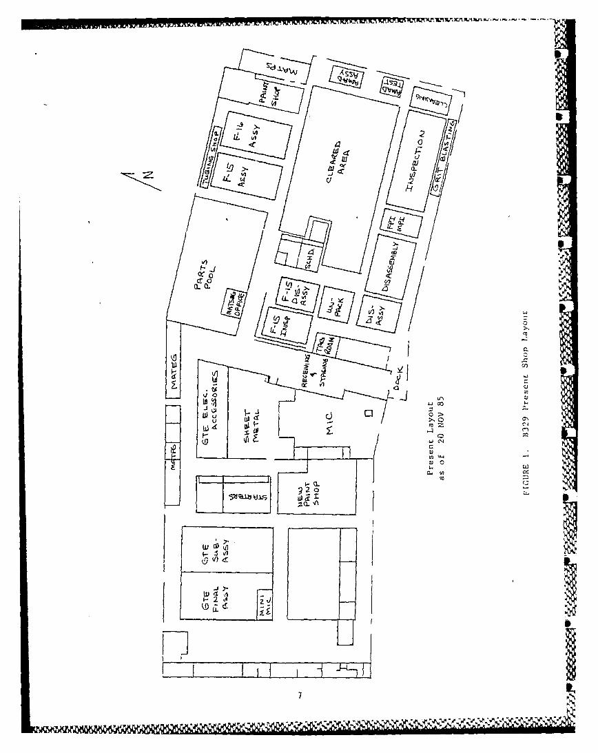
2.1 Material Flow
Understanding the dynamic factors involved with the flow and routing
of material is vital when designing a system that will control thetracking, handling and accounting of material. A basic understanding of
material flow paths was established which allowed the project team to
identify bottleneck areas and choke points within the existing shop
layout.
The present shop layout of B329 is shown in Figure 1. The eastportion of the building is responsible i-r unpacking, disassembly,
cleaning, inspection, painting, parts pool storage and accessory assemblywhile the west Vortion is comprised of sheet metal and electrical shops.
Material Inventory Control (MIC) and GTE/Starter assembly shops. Thecenter aisle of the building which separates the MIC from the parts poolis the main route for material pickup and shipping.
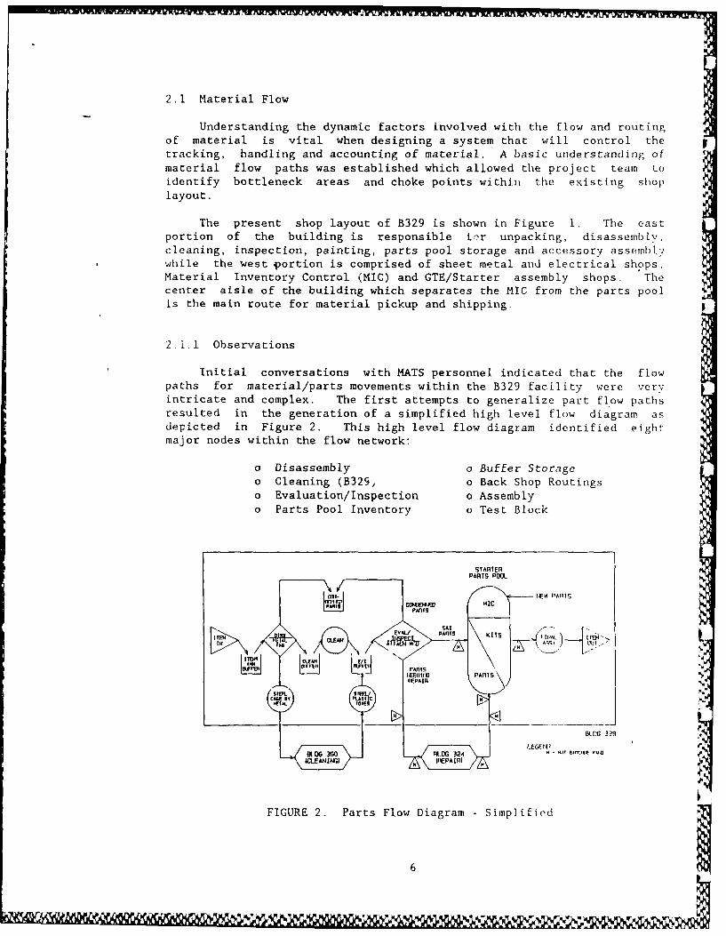
2.1.1 Observations
Initial conversations with MATS personnel indicated that the flowpaths for material/parts movements within the B329 facility were very
intricate and complex. The first attempts to generalize part flow paths
resulted in the generation of a simplified high level flow diagram asdepicted in Figure 2. This high level flow diagram identified eight
major nodes within the flow network:
o Disassembly o Buffer Storageo Cleaning (B329, o Back Shop Routingso Evaluation/Inspection o Assemblyo Parts Pool Inventory o Test Block
STARTERPARTS POOL
Cal. IEW r'AIITS
FVAL/ PAnTs KITS
IN OW
EV.
FIGURE 2. Parts Flow Diagram - Simplified
FellVqrl r~n6
-I 111 PARTS'~
W afwz LL1 C
~I-
CC 0
CZ-
COC
01--nti,
QjI
_ _ IIW4 cA 0
~~22
uj7
2 VI ~.; A *
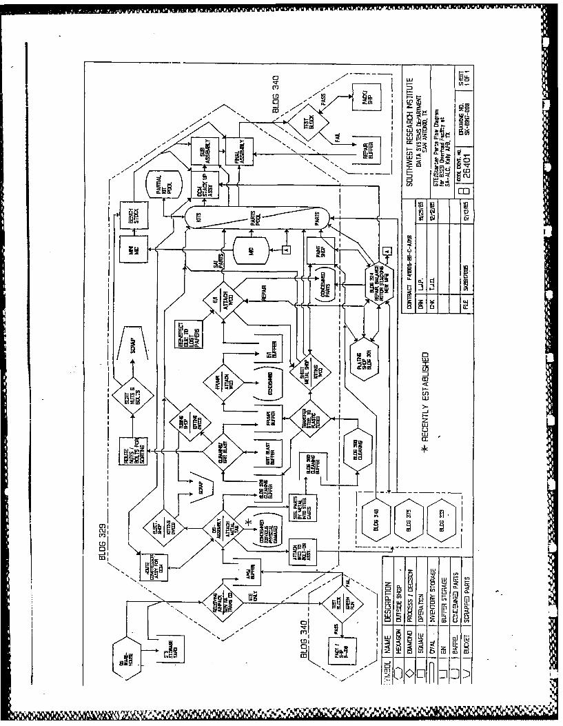
While essentially correct, the simplified flow diagram did not offerthe level of detail necessary for effective flow analysis. The Lea,,concluded that a detailed flow diagram was required to represent factorssuch as conditional branching and nodal relationships. These efforts Sresulted in Drawing No. SK-8917-008 which depicts parts flow on a levelof detail much greater than the initial simplified diagram.
The following paragraphs provide additional insight into the flow ofparts as represented in SK-8917-008.
2.1.1.1 Input
Items (GTEs and Starters) are sent from the Directorate ofDistribution (DS) warehouses to B329 for overhaul and repair. GTEs arereceived in a fenced in storage yard, outside of B329, and wait there
* until receiving calls for them. All other items route directly from thewarehouse to B329 receiving.
2.1.1.2 Receiving
Items are unpacked and are staged for disassembly. An RAtransaction card is generated to acknowledge receipt of the item to theD033 (base supply) data system, which in turn logs to the G004L datasystem that the item has been inducted into the overhaul process and ison-work-order (OWO). After unpacking, personnel will look over the itemand check for obvious physical damage (OPD) and missing components. Ifmissing components are noted a material requisition, form 244, will begenerated under cost code "M" which will request a replacement part fromthe base supply system.
If the item is a GTE unit and it appears to be in very goodcondition, receiving may elect to send it to the test block for a Greenrun (GTEs only). If the GTE passes the test block then a decision can bemade to ship the item out as a servicable asset, in which case MAT wouldreport the job as a B-Job (partial job). If the GTE fails the test blockthen the item is staged in the awaiting maintenance (AWM) buffer.
S
2.1.1.3 Disassembly
Disassembly pulls items from the AWM buffer and starts the teardownprocess. As parts are removed they are identified using a "picture book"and are tagged with the appropriate metal tag containing pertinentinformation of the end item and job number (refer to Section 2.2.1.1 for -an explanation of this tag). The "picture book" contains photographs ofevery part used on an end item. Each photo depicts all of the partscontained in a single plastic tote and is commonly refered to as a"kit". The average GTE consists of between 8 to 13 photos or kits, whilea starter has I or 2 photos representing kits.
The disassembly function acts as a divergence node to route partsthroughout the process. Parts routing includes:
8 N
00
n "cOaz N j
____ ____ ____~ h7_____ ____ ____ ___i
<En'N E-
QJJ
3A
U cLn0w
zww
sh
c'2 I
MW~
ED'
,y.,ov. .tK V

o Bolt-On Components - These components include fuel controls, oilcoolers, oil pumps and radiators that are sent to outside shops(i.e., B333, B348 or B375) which perform overhaul and repairfunctions on the components. Before the component is routed tothese outside shops, a Work Control Document (WCD) is attached tothe part which contains detailed routing instructions. Theseoutside shops perform their processes and route the componentsback to the B329 parts pool for inventory storage.
o GTE Compressor Rotor Sub-Assembly - Prior to these sub-assembliesbeing disassembled, they are sent to the stack-up assembly shopas an On-Condition-Maintenance (OCM) candidate. The OCM teamevaluates the condition of the rotor and determines the level ofwork required to repair the unit. In some cases the rotor
assembly may have sufficient life remaining that it can be builtup into a GTE engine assembly. In other cases it will bereturned to disassembly for further teardown and inspection.These assemblies are routed without any routing documentationattached.
o Electrical Parts - Electrical parts are placed in totes, arouting list is attached and the tote is sent to the electricalshop for processing. The electrical shop cleans, repa'rs andbuilds up an electrical kit that is sent to the parts p.)ol forkit storage.
o B329 Cleaning - A number of parts stay within B329 for cleaning.These parts are placed in totes and are staged in the B329cleaning buffer.
o B360 Cleaning - Parts are segregated by metal type (aluminum,stainless steel, magnesium, etc...) and placed within steel cagesthat are routed to B360 for de-greasing and cleaning. Uponreturning from B360, parts are transferred from metal cages intototes which are dispersed either to the B329 cleaning bufferfor further cleaning, the inspection buffer to await FlourescentPenetrant/Magnetic Partical Inspection (FPI/MPI) inspectionor the sheet metal shop for processing. A large number of partsthat return from the B360 shop are routed to the B329 cleaning
shop for further processing.
o Part Condemnation - Parts with OPD conditions can be condemned indisassembly only after an inspector or a shop planner havereviewed the parts condition. After the parts are evaluated theyare routed to a caged staging room to await furtherdispositioning. This procedure has just rpcently beenestablished in the disassembly shop to reduce the time requiredto report condemned items and receive servicable replacements.Under the guidance of the shop planner, if the condemned partsare complex geometries or made of strategic materials then theymay be sent to a temporary holding account (K account) to awaitfuture evaluation or the development of new repair processes.Refer to section 2.1.1.5 for further insight into the handling ofcondemned parts.
10
- %

2.1.1.4 Cleaning
Various cleaning and grit blasting functions are provided withinB329. The cleaning shop pulls totes from the cleaning buffer andprocesses them using a number of cleaning methods. Following cleaning,some parts may require grit blasting. These totes are staged in the gritblast buffer. All tubing parts are routed to the tubing shop aftercleaning. The tubing shop inspects, scraps and builds up tubing kits,which are sent to the parts pool for storage.
Cleaning also receives plastic bags of nuts and bolts that arebagged during disassembly. These piece parts are cleaned and sent to anarea in the shop for manual sorting, which eventually feeds the benchstock in the assembly areas. Piece part sorting times could besubstantially reduced by using currently available industrial sortingequipment which uses an array of ultrasonic sensors to rapidly identifyand divert work pieces into appropriate bins.
A large percentage of the parts going through B329 cleaning arerouted to the FPI/MPI buffer. Parts pulled from the FPI/MPI buffer areinspected using either FPI or MPI methods, and a determination of thepart condition is made. At this node parts are either condemned or movedon to the Evaluation/ Inspection (E/I) buffer for more extensiveinspection.
2.1.1.5 Evaluation/Inspection
The E/I node is perhaps the most critical node in affecting the flowof parts to the repair shops. E/I performs visual and dimensionalinspections on parts in accordance with appropriate Technical Order (TO)inspection criteria. After a part has been inspected a WCD is attachedto the part which details the processing steps required (Refer to Section2.2.1.2 for an explanation of WCDs). The inspector is then required toassign the part into one of three categories:
" Satisfactory-As-Is (SAI) - Parts in this category have passedall inspections and can be reused in their present conditionwithout further processing. These parts are directly routed tothe parts pool for storage.
o Repair - These parts require additional processing to restore andrepair worn areas. Typically the majority of parts requiringrepair are routed out of B329 and into the machine shop B324 forfurther processing. The actual physical movement of parts isaccomplished using a truck/train service that picks up and dropsoff totes between the two buildings at predetermined times.
There are four primary tasks performed by B324; repair,balancing, rotor stacking and local manufacturing. Localmanufactured parts are routed either to the B329 parts pool orthe MIC, while rotor stack ups flow directly to the parts poolfor storage. Part machining and repairing is accomplished in acollection of smaller shops within B324 that perform numerousmachining/repair operations on parts such as:
11
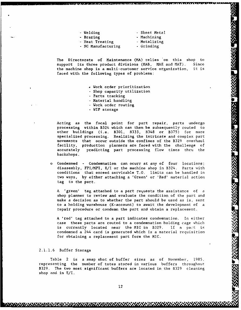
- Welding - Sheet Metal- Brazing - Machining
- Heat Treating - Metalizing- NC Manufacturing - Grinding
The Directorate of Maintenance (MA) relies on this shop tosupport its three product divisions (MAB, MAE and MAT). Sincethe machine shop is a multi-customer service organization, it isfaced with the following types of problems:
Work order prioritization- Shop capacity utilization
- Parts tracking-Material handling S- Work order routing
- WIP storage
Acting as the focal point for part repair, parts undergoprocessing within B324 which can then be subsequently routed toother buildings (i.e. B301, B333, B348 or B375) for morespecialized processing. Realizing the intricate and complex partmovements that occur outside the confines of the B329 overhaulfacility, production planners are faced with the challenge ofaccurately predicting part processing flow times thru thebackshops.
o Condemned - Condemnation can ocurr at any of four locations;disasembly, FPI/MPI, E/I or the machine shop in B324. Parts withconditions that exceed servicable T.O. limits can be handled intwo ways, by either attaching a 'Green' or 'Red' material actiontag to the part.
A 'green' tag attached to a part requests the assistance of ashop planner to review and evaluate the condition of the part andmake a decision as to whether the part should be used as is, sentto a holding warehouse (K-account) to await the development of arepair procedure or condemn the part and obtain a replacement.
A 'red' tag attached to a part indicates condemnation. In eithercase these parts are routed to a condemnation holding cage whichis currently located near the MIC in B329. If a pait iscondemned a 244 card is generated which is a material requisitionfor obtaining a replacement part form the MIC.
2.1.1.6 Buffer Storage
Table 2 is a snap shot of buffer sizes as of November, 1985,representing the number of totes stored in various buffers throughoutB329. The two most significant buffers are located in the B329 cleaningshop and in E/I.
12
TABLE 2Building 329 In-Process Buffer Sizes
---------------------------------------------------------
I Buffer Storage Area No. Totes
--------------------- -----------------I B329 Cleaning 550I Grit Blast 170I FPI/MPI 50I E/I 570 II Paint Shop 120
+--------------------------------------------------------4
It appears that it is difficult for these two shops to maintainenough capacity to keep up with the tote generation rate. The followingpoints offer an explanation as to why these conditions exist:
o Non-Essential Parts Input: Frequent part shortages are beingexperienced in the overhaul process due to the unavailability ofparts from the MIC (base supply system). Management has beensurviving by inputting more end items into the system in order togenerate the required critical parts needed to meet productionschedules. This policy results in saturating the process shops(i.e., cleaning, E/I, B324, parts pool, etc...) with totes thatcontain parts that are not essential to meet productionschedules. Parts are termed non essential if they are generatedfrom an end item that was input into the system due to the needfor specific critical parts (i.e., T-wheels, bearings, etc...).
As the buffer sizes grow totes are stacked one on top of eachother. This makes it very difficult for shop personnel to sortthru the totes and identify contents. A point is reached inwhich the shop foreman looses visibility of the parts within thebuffers and is no longer effective in setting job priorityand selectively scheduling jobs to be worked. A survey of theage of jobs waiting in the buffers indicating some job tagsdating back to 1984.
o Shop Capacity: Analysis of the parts flow process reveals thatthe disassembly appears to have no problem in keeping up with theitem input rate. Estimated disassembly times were quoted by shoppersonnel as being 5 hours for a GTE and 2 hours for a starter.In order to address the bottleneck nodes, MAT management has twomajor initiatives underway. A new automated inspection system(MSAPIS) is planned for installation by late 86 to mid 87 (seeSection 2.2.1.3 for information on this system), while a newcleaning line is currently being designed and is projected forprocurement in mid 87. Refer to Appendix E for references to thedates quoted.
13
2.1.1.7 Parts Pool Storage
The parts pool (PP) is an inventory storage area that has two mainfunctions, 1) receive and store parts and 2) build and ship kits. Note:Section 2.3 of this report covers the parts pool storage area in muchgreater detail. This node acts as the major convergence point in theoverhaul process for parts being received from the following locations:
o E/I (SAI parts)o MIC (new parts)o Paint Shopo Sheet Metal Shopo Repaired Parts (B324)o Local Mfg. Parts (B324)o Bolt on Accessories (B348, 333 & 375)o GTE Rotor Stackups
Parts arrive into the PP area either by overhead monorail, handcarts or train service. As parts are received they are stocked inconventional shelving using the plastic totes. The PP area is dividedinto two sections, Starter parts and GTE parts. Personnel are assignedto one of the two areas.
Kits are built by selecting parts and placing them in a tote. Kitcontents are recorded in the "picture book" corresponding to the type andmodel of end item that the kit is being built for. Kit assembly timesrange from 45 minutes to I hour. Within each of the two areas is an areadesignated for kit storage. The kit storage areas can receive kits fromthe following shops; Electrical, Shpet Metal and Tubing shops as well asthose generated in the PP. Issues from the PP come out in the form oftote kits which are sent to the assembly shops according to productionschedules.
2.1.1.8 Assembly
End items are assembled in three basic stages; i) Stack up, 2) Sub-assembly and 3) Final assembly. The parts pool supplies kits to eachstage of assembly. The nuts, bolts, washers, o-rings, etc that are usedduring assembly are supplied from bench stock which is fed by twosources; the mini-MIC and reclaimed piece parts (nuts, bolts, washersonly).
The stack up assembly stage receives balanced compressor rotorsdirect from B324. As noted previously, OCM evaluations are performed oncompressor assemblies that are removed from GTEs during disassembly.After an item is completely assembled, it is sent to the test block inB340 for test.
14
m-
2.1.1.9 Test Block
The test block dynamically tests the functionality of each item. Therun cycle is controlled by a computer which adjusts key engine controlsbased upon an approved T.O. test procedure. If engine parameters falloutside of acceptable limits then the engine fails the test run and atroubleshooting procedure is used to identify potential problems or mis-adjustments. In JIevere cases the item may route back to final assemblyfor part replacement. Upon successful completion of a test run, the itemis packed and shipped to the DS warehouse, thus completing the overhaulprocess.
15
III I3 1 1 i S i ii 1 1 1 i l i
2.2 Parts Identification
Proper identification of parts using tagging or marking methodsallows data collection equipment (i.e., barcode readers, magnetic stripreaders, surface acoustic wave receivers ...) to rapidly and accuratelyidentify pertinent part information, with minimal touch labor. Thefollowing paragraphs discuss part identification and data collectionmethods currently being used within the B329 facility.
2.2.1 Observations
The two principal part tagging methods used are; metal tags andpaper Work Control Documents (WCDs). Metal tagp are attached to parts toprovide gross identification while the part is subjected to harsh processsuch as chemical cleaning and/or grit blasting, while the WCD provide amore rigourous means of part identification and also acts as a routing
document and process sheet.
2.2.1.1 Metal Tags
As an item is received from the warehouse and brought into thebuilding for unpacking, metal tags are ordered from the Tag room by thedisassembly foreman. The foreman keeps track of the itemModel/Design/Series (MDS), induction date and job type and relays thisinformation to the tag room for tag production. The metal tags arestamped out using an address-o-graph embossing machine. Tag productionis performed far enough in advance so that by the time the item reachesthe disassembly shop, the tags are ready to be attached to parts (withwire) as they are removed from the item.
The format of the present metal tag is shown in Figure 3. Theproduction number, which is a combination of control number and jobdesignator, is used by shop personnel to charge labor hours expended,while the job designator indicates the type of job (i.e., A - overhaul, B- minor repair and C - modification). The Job Order Number (JON)provides a breakdown of the cost period for a given production number.
Control Job Item ModelDesignator Type Number 8
13111A GTC 85 71
Job
Order No. JON 6AA
5289
Julian
Date K
FIGURE 3. Metal Tag Format
16

2.2.1.2 Work Control Documents
The WCD is a multi-function document that performs three mainfunctions; 1) part identification, 2) routing list and 3) process sheet.WCDs are placed into plastic pouches and are attached to parts atnumerous locations along the process. Bolt-on accessories (fuelcontrols, oil coolers/pumps, radiators ...) receive WCDs while indisassembly. Electrical, tubing and sheet metal parts receive WCDs whilein their respective shops. The remaining bulk of parts receive WCDswhile in the Evaluation/Inspection stations.
WCDs contain large amounts of part specific data. The document
length can range fxom one page to many pages depending upon thecomplexity and number of operations required to process the part.Appendix D contains an assortment of sample WCD documents that can beused as references. The field format of a WCD is shown in Table 3. Thisis a fixed format which is used throughout all depots under the Air FnrceLogistic Command (AFLC).
TABLE 3Work Control Document Format
+----------------------------------------------------------------------------------------
Field Pre-Printed I Field I FieldNo. I Field* I Name I Description
----------------------------------------------------------------------I1 Y DATE 'JCD revision date2 Y ORIG/PROD NR Production Number
1 3 1 1 QUANTITY Qty. of parts covered4 Y PRODUCTION SECTION/RCCI Reporting Cost Center5 DATE SCHEDULED I6 DATE COMPLETE7 Y PART NUMBER I8 Y TECH DATA I T.O. References9 ITEM SERIAL NR
I10 Y MODEL/DESIGN/SERIES
i11 Y STOCK NR National Stock Number12 Y OPTIONAL Barcode Symbol, Matl13 MISC14 Y NOUN/END ITEM NOUN Part Description15 Y DISP-STATION Dispatch Station16 Y PDN/OP NO. Shop Symbol/Operation17 Y WORK TO BE ACCOMPLISH Work Description18 MECH Mechanic Stamp I19 P Production Stamp20 Q Quality Stamp
+----------------------------------------------------------------------------------------
*These fields are pre-printed on WCD and are not a required entry for
each part.
17
A unique part numbered item may have more than one WCD associatedwith it. For example, a turbine wheel could have a number of differentrepair procedures that pertain to different areas on the wheel (i.e.,blade tip, blade airfoil, root radius, wheel face, etc...). A WCD isidentified by the production number that is printed in field 2 of theformat. This production number can be used to reference labor standardsfor the operations listed on the WCD.
Changes to WCDs are accomplished using a coordination team comprisedof representatives from planning, scheduling, quality and engineering.If a new procedure is to be added to process a part then the coordinationteam will determine the operations and sequence of steps, establish alabor standard and assign a production number.
The majority of WCDs contain a barcode symbol in field 12 of thedocument format. This code is used by the Maintenance Job Tracking (MJT)
, system to identify parts and track their movement within various overhaulfacilities. The symbol contains a six digit number that is encoded IAWthe DOD LOGMARS code 39 standard barcode format. The number is assignedusing the MJT computer system. Refer to section 2.4.1.1. for additionalinformation regarding the use of the barcode field and its importance tothe MJT system.
The six digit barcode numbers are assigned by the MJT system to eachunique set of data consisting of I) P/N, 2) NSN, 3) Noun and 4)Production Number. Upon entry of a request for a barcode number, theMJT system reviews the database for duplications and assigns a new numberif the part identification data set is unique. In essence, MJT maps thissix digit number to the four pieces of part identification information inits database.
It is important to note that the six digit number encoded in thebarcode symbol is relevant only to the MJT tracking system. Not all WCDscontain a barcode symbol, due to the fact that MJT was not set up totrack every part, but rather only those parts determined by thecoordinating team to merit tracking.
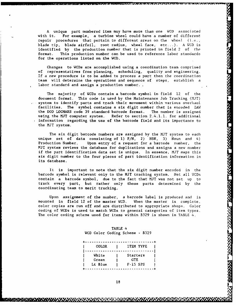
Upon assignment of the number, a barcode label is produced and ismounted in field 12 of the master WCD. When the master is complete,color copies are run off and are distributed to appropriate shops. Colorcoding of WCDs is used to match WCDs to general categories of item types.The color coding scheme used for items within B329 is shown in TABLE 4.
TABLE 4WCD Color Coding Scheme - B329
+ --------------------------------- +
I COLOR I ITEM TYPE II----------------------------II White I Starters
Green I GTE II Lt Blue F-15 SPS
+ --------------------------------- +
18
Every part, while in the overhaul process, must be tagged (metal orWCD) at all times. In the event a part loses it's tag or WCD, proceduredictates that the part be routed back to E/I for inspection. This is toensure that parts do not bypass critical process steps such asinspection, evaluation or repair.
2.2.1.3 Laser Etched Metal Tags
A new inspection system termed the Multi Station Auto PromptingInspection System (MSAPIS) is being developed under a government contractby L&K Tools for the MAT division. The system will implement 20automated dimensional. work stations which will be used to inspect andevaluate various part geometries and dimensions. Delivery of the systemis expected in two phases;
28 MAY 86 Phase I - Partial installation of the host system, laseretching equipment and four inspection workstations.
25 SEP 86 Phase II - Installation of balance of work stations,
The auto prompting feature of MSAPIS will display a WCD on a CRTscreen for operator viewing. WCD documents will be printed out at theinspection station on command and should effectively eliminate theshelves of WCDs that are presently required to store the printed copies.
The host computer system will consist of two DEC VAX 11/780s whichwill be dedicated to the control of the MSAPIS system. Current plans donot include establishing communication interface links between theMSAPIS hosts and any other computer system.
Each part entering the inspection cell will have a metal tagattached that contains a laser etched barcode symbol. Metal tags will beordered and attached to the parts during disassembly, similar to thepresent tagging process. Only those parts requiring a visual ordimensional inspection will be tagged with the laser etched barcodedtags.
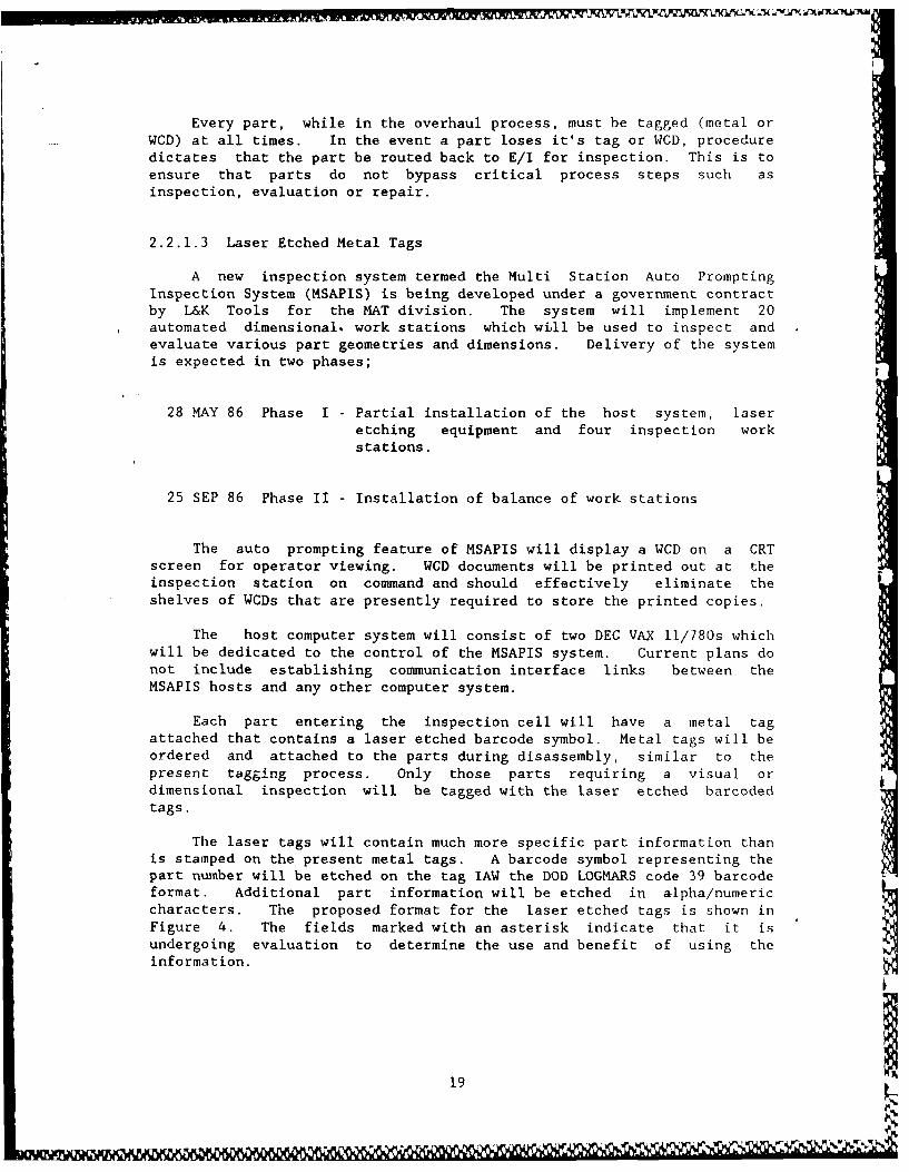
The laser tags will contain much more specific part information thanis stamped on the present metal tags. A barcode symbol representing thepart number will be etched on the tag lAW the DOD LOGMARS code 39 barcodeformat. Additional part information will be etched in alpha/numericcharacters. The proposed format for the laser etched tags is shown inFigure 4. The fields marked with an asterisk indicate that it isundergoing evaluation to determine the use and benefit of using theinformation.
19
NSN
MDS2910 00 113 2003YP
Noun GTCP165-1
SHROUD, FUELJulian Date 86140
_-xxxxxxx iSerial No. yyyyyyy I BARCODE SYMBOL I
zzzzzzz _ __
* Sequence No.
* Index No.
Part No.
FIGURE 4. Proposed Laser Tag Format
The MSAPIS program will upgrade the tag room from address-o-graphmachines to laser etching barcode equipment. The expected capacity ofthe tag room is to produce approximately 400,000 laser tags/yr. Tagproduction is estimated to run between 25 - 35 seconds. The lasertagging equipment will be controlled by an IBM PC which will contain adatabase of part information arranged by GTE/starter type. It isunderstood that no external communication links are plan, ed for the IBMPC laser etching control computer.
Although the MSAPIS is a completely stand alone, dedicated system,it appears that it has the potential of providing WIP tracking scatusinformation of parts within the inspection work area. From this point itmay be worthwhile to establish a communication link between the MSAPISsystem and any future parts pool inventory control system, to providethe status of parts within inspection.
20
e-
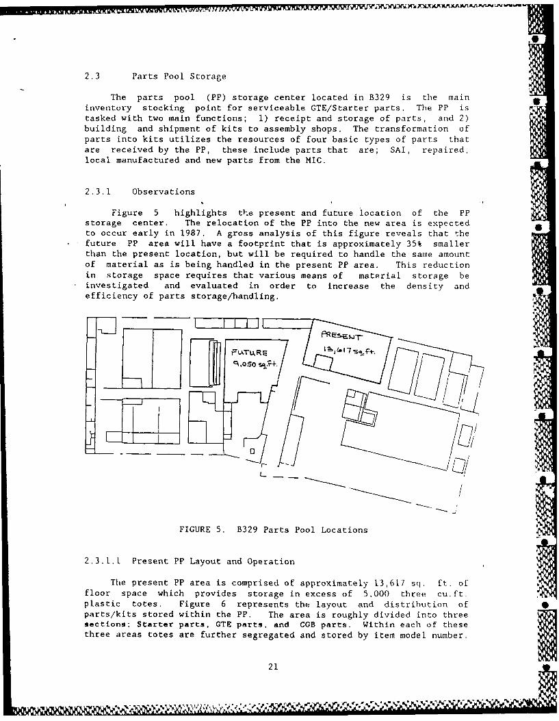
2.3 Parts Pool Storage
The parts pool (PP) storage center located in B329 is the maininventory stocking point for serviceable GTE/Starter parts. The PP istasked with two main functions; 1) receipt and storage of parts, and 2)building and shipment of kits to assembly shops. The transformation ofparts into kits utilizes the resources of four basic types of parts thatare received by the PP, these include parts that are; SAI, repaired,local manufactured and new parts from the MIC.
2.3.1 Observations
Figure 5 highlights th:e present and future location of the PPstorage center. The relocation of the PP into the new area is expected 6to occur early in 1987. A gross analysis of this figure reveals that the
, future PP area will have a footprint that is approximately 35% smallerthan the present location, but will be required to handle the same amountof material as is being handled in the present PP area. This reductionin storage space requires that various means of material storage beinvestigated and evaluated in order to increase the density andefficiency of parts storage/handling.
-M
FIGURE 5. B329 Parts Pool Locations
2.3.1.A Present PP Layout and Operation
The present PP area is comprised of approximately 13,617 sq. ft. offloor space which provides storage in excess of 5,000 three cu.ft.plastic totes. Figure 6 represents the layout and distribution ofparts/kits stored within the PP. The area is roughly divided into threesections; Starter parts, GTE parts, and CGB parts. Within each of thesethree areas totes are further segregated and stored by item model number.
21
-~ *,~*% -XV'~4'Y\4' ~.. '~s~ - - X.
KOT S~tP91w=
U-01
,.- - -
-- (Y
U) -)
-.9 6
d) dLf o w
-L 4 LL
- -N -2
- 'I - -C2 919 ~
a-i -- j 22
Parts arrive in totes and are placed on a conveyor which sends thetotes thru a wall into the parts pool area. The totes may contain morethan one part type (i.e., spur gears, pinion gears, etc...), or maycontain quantities of a single part type. The policy is that all partsmust be received with a WCD attached to the individual part. The teamobserved totes with quantities of a single part type that did not have aWCD attached, instead a stack of WCDs for the parts were placed in thetote but not attached. It is not known which shop originated thistechnique or why it is being used or tolerated.
As the totes queue up on the receiving conveyor they are manuallysegregated and moved into three locations; totes which contain GTE parts,totes with CGB parts and totes with starter parts. The color of the WCDaids in performing tote segregation. After the parts in a tote areidentified the tote is moved along the conveyor and sent to theappropriate section. The receiving rate of totes is not continuous buttends to be sporadic in nature. This may be due to the method oftransportation used to move totes from the B324 repair shops and E/Iinspection area (e.g. train service and push carts).
After the totes have been moved into their respective areaspersonnel select totes and route then down the appropriate rollerconveyor until the appropriate shelf and bin is located for the part tobe stored. The parts are removed from the tote while on the conveyor andare placed in the tote which is stacked in the shelving. This action isperformed manually since tote weights tend not to exceed 50-55 pounds andthe tote size is fairly manageable. Parts range in size from cubicinches to a maximum of two cubic feet.
The shelving system is completely manual and consists primarily ofopen frame tote box holders and steel shelf units. A conventional cubematrix approach is used to indentify part/tote locations. Figure 7depicts this method of indexing shelf locations.
() /... /
E
D
Legend:C
"(1) Row No.
B I Shelf No.A Bin No.
A
/
FIGURE 7. Parts Pool Shelf Indexing Method
23

At the end of every row of shelves is a clipboard that contains adocument called a shortage sheet is attached. The purpose of thisdocument is to keep a running inventory of the parts listed and tohighlight part shortages that are holding back the shipment of kits. Theshortage sheets are used by the 'Parts Busters' group whose duty it is toorder and follow up on the procurement of the critical parts.
Frequent manual inventory counts of the PP are performed each monthto adjust inventory levels on the shortage sheets. The current inventorypolicy is to maintain atleast a two week backlog of parts in the PP.
The kitting function is essentially a one man operation. Using the"picture book" as a guide, parts are selected and assembled into a kitlAW the parts shown in the kit photographs. Since parts are stored byMDS (model) designation they tend to be located in close proximity to oneanother, which in turn promotes kitting.
Typically a GTE will consist of between 9 and 14 tote/kits while astarter will consist of I or 2 totes. Kitting times range from 30minutes to 1 hour. These times are highly dependent upon theproficiency and experience of personnel performing the job. At the timethe PP was surveyed, very few GTE kits were stored in the PP, while onthe other hand starter kits consumed a row of shelves for kit storage.
The PP area requires a work force of 30 personnel which are dividedinto two groups; 13 in the GTE group and 17 in the starter group. Eachgroup is controlled by a group supervisor who has the responsibility forissuing the daily work requirements and priorities to meet production
schedules.
Parts pool personnel serve in multi-functional capacities withduties that include receiving, stocking, logging, kitting, issuing andexpediting material. Approximately half of the total PP work force areassigned expediting duties outside of the PP area.
2.3.1.2 PP Throughput Capacity
An analysis of throughput capacity for the parts pool was conductedto quantify the average number of totes/baskets that arrive and areissued from the PP. Prior to the analysis being performed, certainassumptions had to be stated.
These assumptions were established under joint agreement betweenMATS personnel and the project team. Items A - F listed in Table 5 showthe values that were assumed to support the throughput calculations. Adescription of each assumption should help to define how the results were
derived.
24
I. M~
o Assumptions:
A - Yearly Production Units - i/yDefines the average number of items (GTEs and starters) -Ithat are overhauled on a yearly basis.
B - Average No. Parts/Item Units - p/iGives the average number of parts for an item. This doesnot necessarily include bench stock parts such as o-rings,nuts, bolts, washers, etc.
C - Work Days/Year Units - d/yThis nuiqber is the difference bptween the number of weekdays in a year (260) less holidays (10) less normal daysassociated with vacation and/or sick leave (10).
D - Work Hours/Day Units - h/dThis number is the difference between the duration of thestandard work day (9 hours) less time for lunch and breaks(I hour).
E - Average No. Parts/Totes Units = p/tThis quantifies the average number of parts that arecontained in totes that are received into the parts poolfor stocking. The source of these totes will be the E/Ishop, machine shop (B324), other back shops and the MIC.
F - Average No. Baskets/Item Units - b/i
This relates to the average number of baskets it takes toassembly an item. In other words, the average number ofbaskets required to be sent from the parts pool intoassembly in order to build an item.
Rows G and H contain the results of the calculations using thevalues listed in Table 5. The foumulas that were used to perform theanalysis are listed below Table 5 and were constructed using the itemdesignator listed in the left hand column of the table.
The result of the analysis indicate that an average of 32 totes/hourarrive into the parts pool while an average of 17 baskets/hour are issuedfrom the parts pool. In this case a tote and a basket are one in thesame but for purposes of consistency, the term basket was used toindicate outgoing totes because this is what the shop personnel arefamiliar with.
At first glance it would appear that the PP receives more totes thanit ships out. In a physical sense this is true but when the number ofparts per tote are taken into account the two balance out. This is dueto the assumption that incomming totes contain on the order of 8 to 10parts while outgoing totes containe between 12 to 20 parts. This equatesto a throughput capacity of approximately 280-300 parts per hour, input
and output.
25

TABLE 5B239 Parts Pool Throughput Capacity
+----------------------------------------------------------------------------------------
1 1 I 1 1 1 1 1IITEMSI DESCRIPTION I UNITS I GTE STARTERS I TOTALS I
--------------------------- I-------I ------- I ------- I 11A I Yearly Production I i/y 1600 6000
I- ----------------------- I------ ------ I ------- I -----B I Average no. parts/item I p/i 150 50
---- I-----------------------I------I ------ - ------ I -----C No. work days per year I d/y 1 _240 240
---- I-----------------------I------ ------ - ------ I II----D I No. work hours per day I h/d 1 8 1 8
----I ------------------------- I-------I ------- I ------- H IE Avg. no. parts/tote (IN) I p/t 1 8 i 10 11 1
---- I-----------------------I------ ------ - ------ I II----F Avg. no. baskets/item (OUT) I b/i 12 2
G I INPUT - totes input per hr t/h 16 1 16 32into the parts pool
I---
H OUTPUT - baskets output per b/h i10 1 7 17I fhr from parts pool
-------- ===---- - - - - - - - - - - -
Legend:
i - item p - part b - basket t - tote
y = year d - day h - hour
Formulas:
Input: G - ([(A / C) x B] / D) / E
Output: H = [(A / C) x F] / D
2.3.1.3 Future Parts Pool Location
A proposed plan calls for the relocation of the existing PPoperation into an area of the shop that is more centrally located withinB329. The projected move date is set for March, 1987 (see Appendix E forreferences). Figure 8 illustrates the future area which is contained inthe dashed line. Since this area is irregular in shape and contains 35%less floor space than the existing PP area, the project team concentratedon evaluating the feasibility of utilizing high density, mechanizedmaterial storage equipment.
26
BLDG. 329
BREAKROOM MATEC,.
GTE ELEC.
CONTROL AND
SYSTEMSTARTERS (FLATLA P, E
zz
PAINT 1.CZSHOPI
B E R aN R+ D.
1=30
FIGURE 8. Parts Pool Area -Future
27

Two factors pertaining to the new area initially concerned the team;1) the irregular shape of the area, and 2) the overhead routing of steampipes which reduced the ceiling clearance to 13 feet under the pipes.Both features of this area contributed to reducing the effective unitstorage cube available for material storage equipment. With theseconstraints in mind the following material storage methods wereconsidered:
o High Density Shelving - The use of HD shelving proved to beimpractical due to the irregular shape of the area which tendedto restrict storage space. This form of material storage wouldhave resulted in a very crowded floor, narrow aisles andeffectively no 4rea for future expansior or contingency planning.
o Mezzanine Storage - An optional configuration for the HD shelvingsystem would be the addition of a mezzanine floor directly abovethe main floor. This approach was not feasibile due to theceiling height constraints of the new area and the need forfrequent tote movement between floors.
o Mini-Load Automated Storage/Retrieval System (AS/RS) - Although aviable alternative, the mini-load system posed certainconstraints to the response times of tote storage/retrieval aswell as restricting access to totes in the event of a mechanicalfailure or power outage. Other factors included the complexityof the installation, lack of flexibility in relocating theequipment into another area and the costs associated with anASiRS system for this area.
o Vertical Carousels - The feasibility of using vertical carouselsas the main method of paft storage was questioned for thefollowing reasons;
- The chances of interference or collision of odd shape oroversize parts is increased due to the enclosure of theequipment.
- Access and visibility of totes is more difficult in event ofmechanical failure or power outage
- The ceiling height limitations of the area forces thespecification of vertical carousel heights that are notcondusive to their application. Carousel height between 18-20 feet would be result in a more efficient application.
- The cost per unit cube of storage is higher with verticalcarousels as compared to horizontal carousel equipment.
However, the team did recommend that vertical carousels beconsidered for small parts storage as is the case in the starterkitting/de-kitting area which is located in the lower right handcorner of the existing PP area as shown in Figure 6.
28
. 11- 111 A, ON - - ,
o Horizontal Carousels - The best overall candidate for partsstorage rested with the horizontal carousel method of storage.Horizontal carousels offered many features that the teambelieved were well suited for the new area. These include;
- High density storage with good space utilization
- Flexibility with storage bin configurations
- Ease of maintenance and good access to drive motors
- More easily handles odd or oversize parts
- Ceiling clearance allows for efficient carousel heights
- Allows access to parts in event of power outage or failure
- Relocation of carousels to other areas is relatively easy
- Modular construction eases installation
2.3.1.4 Suggested Parts Pool Layouts
Appendix F contains the seven layout Jrawings which are designatedas drawing numbers SK-8917-001 thru SK-8917-007. The words "PROPOSED"and "POTENTIAL" should be kept in mind when referencing these drawings.This is due to the fact that a rigorous analysis has not been performedto substantiate the designs and determine the effects on material flow,facility constraints and labor requirements.
While a detailed layout design is beyond the scope of this study,the seven layouts represent preliminary ideas on how the floor space andavailable storage volume could be utilized with various storage equipmentconfigurations.
The initial analysis of the proposed parts pool area yielded fourpotential material storage layouts SK-8917-001 thru 004. These layoutswere included in the interim report and were evaluated during a reviewmeeting that was conducted on January 23, 1986. This meeting resulted inthe further definition of the future PP layouts requirements andsubsequently the generation of layout numbers SK-8917-005 thru 007.
This latter set of drawings ( numbers 005 - 007) are all similar interms of the numbers and types of storage equipment that are used (i.e.,12 ea horizontal and 2 ea vertical carousels), but differ in the way thatthe equipment is integrated into the PP layout based upon the following
list of requirements that were compiled during the review meeting.
o Main Storage - 12 ea/12 ft, 60 bin horizontal carousels combined.ith 2 ea/13 ft, 24 shelf vertical carousels. This configurationof storage equipment allows for approximately 43% more storagecapacity than the existing PP area which will provide for futureworkload additions or production increases.
29

o Computer Control Room - An enclosed control room with roomdimension of at least 15 X 10 dimensions should be located in thefuture PP area to provide environmental control for all computerand peripheral equipment.
o Restricted Storage Area - An area should be reserved for thestorage and handling of condemned parts and parts awaitingplanner assistance. The team recommends that access to this areabe limited to outside the PP only to preclude the chance ofmixing good parts with parts whose status is questionable.
o Carousel Kit Storage Capacity - While the main items stored inthe horizontal carousels will consist of parts, the carouselstorage equipment should have the capacity to store enough kitsto support production for one. The majority of the items storedin the carousels will be parts and not kits, but some residualkit storage should be allowed for surge situations. Kit storagecapacity will range from 120-140 totes.
o Train Se-vice Drop-off - Entry of totes into the future PP areashould be accessible by the B329 train service that runs throughthe main aisle of the building. The receiving area of the PPshould have the capacity to handle a surge of 40 -60 totes.
The primary means of tote handling within the future PP area willbe conducted using conventional roller conveyors. This method ofmaterial handling provides both a simple and cost effective form ofhandling and routing totes. It may be advantageous to use power rollerconveyors or transporter systems inicertain sections of the route due tothe length of the movement, restricted aisle widths or the need for totediverting to carousel work stations.
2.3.1.5 Storage Equipment Specifications
Two types of storage equipment have been used in cach of thelayouts to provide for tote storage; these include horizontal andvertical carousel systems. The initial recommendations listed belowconsist of generic equipment specifications that appear to possess thetype of attributes that would promote high density storage capacity, easeof maintenance and good operator interface.
o Horizontal Carousels:
Height - 12 ft 10 ftNumber of bins (B) - 60 50
Number totes/bin - 12 10Bin dimensions - 21"W x 22"D x 144"H 21"W x 22"D x 120"H
Storage volume (BxV) - 2,310 cu.ft. 1,604 cu.ft.
30

o Vertical Carousels:Height - 13 ft 15 ft
Number of shelves(S) - 24 28Shelf dimensions - 89-1/4"W x 15-1/4"D x 10-1/8"H (same for both)Shelf volume (V) - 7.97 cu.ft. 7.97 cu.ft.
Storage volume (SxV) - 191 cu.ft. 223 cu.ft
It is anticipated that the procurement of the new mechanized storageequipment will include new storage tote containers for use exclusively inthe parts pool area. The existing tote boxes will not fit the standardcarousel bins and using them would require special oversized non-standard bins. Each bin of the proposed horizontal carousels will have
, a capacity for 10 or 12 shelves or totes (depending on carousel height).while the vertical carousels will consist of smaller bins that will varyin size to accommodate the numerous piece parts that will be stored init.
Suggested tote sizes have been included to allow for a comparativeanalysis of storage utilization of the existing storage system with theproposed storage layouts. Actual tote sizes cannot be specified untilpart sizes, storage quantities and kit contents are analyzed for eachpart/kit.
Each tote has associated with it an internal and external volume.The external volume is the gross volume required to store the tote in thestorage equipment. The internal volume is the net volume available forpart storage.
o Tote Containers:
- Existing Totes
+ External volume of 4.4 cu.ft. with dimensions of 27"L x27"W x IO-1/2"H.
Vt(e)e - 4.4 cu.ft./tote
+ Internal volume of 3 cu. ft. with dimensions of22-1/2"L x 22-1/2"W x 10-1/4"H.
Vt(i)e - 3.0 cu.ft./tote
- New Totes for Horizontal Carousels
+ External volume of 2.7 cu.ft. with dimensions of23-3/4"L x 19-3/4"W x 10-1/4"H.
Vt(e)h - 2.80 cu.ft./tote I+ Internal volume of 2.55 ct, ft. with dimensions of 22-1/8"L
x 18-1/8"W x 10"H.
Vt(i)h - 2.30 cu.ft./tote
31
-New Totes for Vertical Carousels
+ The vertical carousels have an effective storagevolume of 7.97 cu.ft./shelf. The size and shapes ofthe small pa:ts to be stored therein will allow almostcomplete utilization of the available space.
+ Gross external volume of 7.97 cu.ft./shelf withdimensions that will vary depending upon the partsbeing stored.
Vt(e)v - 7.97 cu.ft./shelf
+ Net internal volume of 7.57 cu.ft./shelf which willbe on the average approximately 5% smaller than theexternal tote volume available due to the wallthicknesses of the totes used.
Vt(i)v - 7.57 cu.ft./shelf
2.3.1.6 Volumetric Analysis of PP Layouts
A volumetric analysis was conducted to compare each of the proposedlayouts to the present PP layout. To 'facilitate this analysis thestorage density and cubic space utilization associated with each layouthad to be quantified. A gross analysis of the present and future PPlocations indicates that major differences exist between the two areas.Table 6 summarizes the differences in attributes between the twolocations.
The project team had four concerns pertaining to the future partspool location:
o Overhead steam pipes - These pipes effectively cut off two feetof ceiling height over 9% of the floor area. It appears that thepipes will not have the impact on storage capacity that the teamanticipated if horizontal carousels are used.
o Building posts - The future PP location contains eleven postswithin the core section of the room. This compares with only twoposts for the existing area. Our concern was that the postswould hinder and restrict the installation of mechanized storageequipment. The use of horizontal carousels will allow thecarousel equipment to be installed around these post thusminimizing the effect of the posts on parts storage.
32

TABLE 6Parts Pool Room Attribute Comparisons
+-------------------------------------------------------------------------------------------------
ATTRIBUTE I PRESENT ROOM FUTURE ROOMI
--- ------ -------------------- --------------------------- IILocation I Adjacent to the E/I shop ICentrally located to all
I shops in the building. I--- ------ -------------------- --------------------------- I
* Posts I2 11I--- ------ -------------------- --------------------------- IIObstructions INone jLarge steam pipesI----------------------------------- --------------------------- IAccess IGood access from two IGood access from only
I Isides of the room, other one side of the room.two sides blocked by A sloping ramp and a
Iwalls. I4 ft. wall impair twoI I walls. Last wall blockedl
by the fence for the MIC. I--- ------ -------------------- ---------------------------IICeiling I15 ft. over 100% area j15 ft. over 91% areaIHeight jI13 ft. over 9% area
(due to pipes)
--- ------ -------------------- --------------------------- IIShape (Rectangular ITrapezoidal--- ------ -------------------- --------------------------- IDimensions I153' 114'
II 36.5' I 91' \ 96'II __ 189'I 1 \
I Ijlessl 20 ' 1 1 ___ pipes I1 _1 _ 1 1_ _ 85'
--- ------------------------------ I------------------------IArea IAp - 13,617 - 730 IAf - 7,735 + 1315
- 12,887 sq.ft. j - 9,050 sq.ft.I--- ------------------------------I ----------------------- IIVolume Vp - 12,887 x 15' IVf - 8,266 x 15' +(room) j - 193,305 cu. ft. I784 x 13'
--------------------------I - 134,182 cu.ft.--- -- -- -- -- -- -- -- --- -- -- -- -- -- -- ----------------------
ITotes IGTE - 2,200 IDependent upon layoutIStored I Starter - 3,050 Ibut not less than;
I Total 5,250 totes Minimum 8,600 totes------------------------------------------------------------------------------------------------
331
o Irregular shape - The irregular shape does reduce the effectiveutilization of the room volume and reduces equipment layoutoptions but it remains to be seen what impact this will have onthe final design.
o Room access - Access to the future PP room will be restricted dueto a 4 ft. high retaining wall, ramped walk way and perimeterfence for the MIC room. These leave only one side of the roomwith good access to parts while stored in the equipment.
As previously mentioned, horizontal and vertical carousels werejudged to be good candidates for effective material storage in the new PPapplication. Within each equipment category two sizes were specified;
Horizontal carousels - 12 ft and 10 ft heights
Vertical carousels - 15 ft and 13 ft heights
Table 7 provides a list of equipment selections for each of thelayouts. All layouts use, as a minimum, twelve each of the 12 ft. highhorizontal carousels. This group of twelve represent the core of thematerial storage equipment and is responsible for the high volumeutilization and storage density that is attained in the layouts.
TABLE 7Storage Equipment Configuration Chart
+------------------------------------------------------------------------------
Parts STORAGE EQUIPMENTPool Horizontal VerticalLayout Carousels CarouselsDesign 10' 1 12' 13' 15'Options 50 bin 60 bin 24 shelf 28 shelf
----- - -------------- ---------- ----------SK-8917-001 12 1
.------------- ---------- ---------- --.-------- ---------SK-8917-002 12 5
.---------- ----------- ---------- -------- ----------SK-8917-003 12 9 5
--- --------------------- ---------- ---------- ISK-8917-004 4 12 2
--- --------------------- ---------- ---------- ISK-8917-005 12 2
--- ----- I----- ---------- ---------- ---------- ISK-8917-006 12 2
--------------- ------------ ---------- ---------- ISK-8917-007 12 2------------------------------------------------- I
34
A . ---|,% ~ ~
Table 8 summarizes the data that was generated in performing tievolumetric analysis of the various PP layouts. Each column of the tablehas been assigned a letter to aid in explaining the calculations forcolumns C,E,G,H,and I. The legend of the table briefly describes eachcolumn and notes the formula that was used to generate the information.
As a general conclusion, each proposed layout resulted in increasedstorage capacity within a reduced room volume, thus volumetricutilization increased. In other words, for every available cubic foot ofvolume, the proposed layouts used between 84 to 128% irore of this volumeto store parts as compared to the existing PP area (refer to column I).
Likewise, overall- storage density increased proportionally. Theproposed layouts allowed 27 to 58% more part storage volume as comparedto the existing area (refer to column H). These numbers provideencouraging results acknowledging the fact that the total available roomvolume of the new PP location is more that 30% smaller than the existing
location.
TABLE 8Layout Volumetric Comparisons
--------------------------------------------------------------------------L Room Bin I Bin I Tote I Tote I Tote I Tote IlComparisonsl
0 Volume Volume I Util I Vol-e iUtil-el Vol-i lUtil-ill Dens UtillC (A) (B) I(C) (D) (E) (F)I (G) i (H) I(I)I
cu.ft. I cu.ft. I % I cu.ft.l % cu.ft.1 % H % I % I
P 193305 28000 14.5 1 23100 12.0 15750 1 8.1
i1 134182 27911 20.8 24383 18.2 20053 14.9 11 27 84 1
2 134182 28675 21.4 25147 18.7 20777 15.5 11 32 91 1
3 134182 30554 1 22.8 27026 20.1 22561 16.8 11 43 107 1
4 1 1182 34518 1 25.7 30629 22.8 24834 18.5 11 58 128
5 1 ------.----..---.. 0-45 ---8. 3 20---- 1---1-------1 5 1 134182 28102 21.0 24574 18.3 1 20234 15.1 I1 28 86
I6 I134182 I28102 I21.0 I24574 I18.3 I20234 I15. iI 28 I86
7 134182 28102 21.0 24574 18.3 20234 15.1 i 28 86---------------------------------------------------------------------------------
Legend:
P = Present PP areaRoom Volume (A) - Total room volumeBin Volume (B) = Total storage bin volumeBin Util (C) = Bin utilization ratio B/A.Tote Vol-e (D) - Total external tote volume
Tote Util-e (E) Tote (external) utilization ratio D/ATote Vol-i (F) - Total internal tote volume
Tote Util-i (G) - Tote (internal) utilization ratio G/A
35
-- U-. -*~* U ~- - I - % ~ \~, *~-~~* ~* *~%
Comparisons:
Dens (H) - Density factor. Change in internal tote storagecapacity between the present (p) layout andproposed (1) layouts.
f(FI-Fp)/Fp] x 100
Util (I) - Utilization factor. Change in storage cubeutilization between the present (p) layout and
proposed (1) layout.
[(Gl-Gp)/Gp] x 100
At this time it is important to note that the future parts pool room Soffers enough cubic space capacity to allow for the storage and controlof material that is presently located in the existing PP area. Effectiveutilization of this volume requires the use of mechanized storageequipment in the form of horizontal and vertical carousels.
Until a detailed analysis of inventory activity is performed, it isnot wise to assume that all parts stored in the existing PP area need tobe located in the future area. Through the use of computerized inventorycontrol, high density" storage and accurate part identification proceduresit may be possible (and probable) to reduce the amount of inventorystored in the PP.
2.3.1.7 PP Personnel Requirements
The incorporation of computer controlled mechanized storageequipment will alter the personnel requirements of the future PP areacompared to the current staffing levels of the personnel that areassigned to the existing PP area. This analysis does not take intoaccount for shop floor parts expedition. Due to the expected throughputrates that are planned (300 parts/hr), the future PP has been classifiedas a high volume area.
When using horizontal carousels in high volume applications theproject team recommends the assignment of one person for every twocarousels. This allows personnel to increase throughput efficiency byallowing them to service one carousel while the other carousel is beingindexed for the next action. A preliminary analysis of the laborrequirements for layouts SK-8917-005 thru 007 indicates the following:
Carousel Operators-Horizontal 6- Vertical 1
Systems Operator ITote Routers 2
Relief Man 1 0
Total Personnel - 11
36I

In order to support this high volume load and be able to providegood response times, the following items should be considered for usewith the horizontal carousels:
o Carousel speed should be increased to 80 ft/min to reduceresponse time. The standard speed is normally 60 ft/min.
o Carousel bins should be indexed for side angle picking. The willallow personnel to position themselves in an area between twocarousels, and thus service the bins with minimal movement (referto Figure 9).
o Man lifts will be required to allow personnel to pick parts fromreaches that are 5 feet or higher. The team recommends the useof a low profile scissor jack lift with a rated capacity of 1000lbs. An integrated work station incorporating sound humanfactors and ergonomic methods should be designed to handle a CRT
terminal, tote containers and provide dual side access tocarousel bins. Figure 9 depicts a conceptual design of such acarousel work station server. Actuation of the lift could beprovided by a foot switch or panel switch.
Tote *-LiftPlatform
CRT
CC
aa
r r
Bin 0U U
s s
e e
FIGURE 9. Proposed Carousel Work Station Layout
37
1& W 50501 J pi 411ii 1
2.4 -Material Control System
The accurate tracking of material movements and timely reporting ofinventory stock levels are important criterion of all integrated materialcontrol systems (MCS). In an automated MCS a central host computer cancoordinate the receiving, storing, picking, order filling, orderinquiries, inventory checks and shipment scheduling. It can assignstorage locations, guide parts into storage and can operate and controlautomated storage equipment to follow a retrieval sequence to support kitbuilding.
2.4.1 Observations
The preliminary design of an MCS for the B329 operations requiressystem attributes that address each of the following functions:
o In-Process Parts Tracking- Tagging Methods- Data Collection
o Storage Equipment Control- Equipment Interfaces- Automatic Indexing- Tote Identification
o Inventory Control- Part Identification
- Tote Locations
- Stock Levels- Order Processing
o Decision Support Utilities- Pipeline Analysis- Condemnation Analysis
2.4.1.1 In-Process Parts Tracking
Parts tracking is involved with the identification of parts and themonitoring of part movements through data collection stations. Knowingthe type, quantity, location and status of parts that are in-process,allows management to identify potential part shortages or shopbottlenecks. The Maintenance Job Tracking (MJT) system was developed toaddress these functions of material tracking.
MJT, an AFLC wide sponsored data system designated as C046, wasdeveloped under contract by the Ford Aerospace Information Systemsdivision. Using Tandem computer equipment as the system host, MJT wasinstalled in all five ALCs to provide for the tracking of parts withinand between facilities.
38

The system installed at SA-ALC, Kelly AFB includes over 140 CRT/wandterminals dispersed throughout the majority of MA far;ilities. Table 9lists the number of barcode wand data collection stations that arelocated within each building. This data was obtained from Mr. J.Sepulveda/MAWSP directly from an MJT transaction listing.
TABLE 9
MJT Data Collection Stations
+---------------------------------
Building 1 Number ofNumber j Station I
-------------------------- I301 1
----------- -------------- I324 20
----------- -------------- I329 12 *
----------- -------------- I333 7
----------- -------------- I348 5
----------- -------------- I360 15
----------- -------------- I375 40
+---------------------------------
* Note: Actual count indicates five (5) MJT terminals located
near and/or within the existing parts pool area.
Presently, the utilization of the MJT system is low and for allpractical purposes it appears that the system is not being used. Infact, among the five ALCs, Kelly AFB is the only one that has voiced aninterest in re-establishing MJT as a tracking system. This statement ismade knowing that a request, to authorize Kelly to modify MJT, has beensent to AFLC command from the MAWS systems office. It is not known ifMAWS will be granted authority to modify MJT, in light of the developmenteffort that is underway on the DMICS data system (Depot Maintenance
Integrated Communications System).
Without getting into the details of DMICS applications, it wasclearly understood that the MJT host computer was being quite heavilyutilized for development efforts, and that priority for the MJT systemwas currently set at 5th or 6th down the list and dropping. Since DMICS
is not currently available for the MA users, it seems evident that AFLCcommand has allowed a situation to occur in that the MA user has beenleft unsupported, without the aid of an effective parts tracking system,and will remain so for another 3 - 5 years until the DMICS system canfill the tracking function.
391
Acknowledging the fact that the MJT system is a tracking system thatis curently available to MA users, a number of conditions exist whichhave reduced the capacity of MJT to perform the tracking functioneffectively. Discussions with various MA personnel indicate a range ofreasons for its lack of use which include :
o Response 'rime - Reports of poor response time have been heardfrom nearly every person interviewed. The team has been informedthat response times for interrogation type transactions rangefrom 3 to 20 minutes. Some possible reasons for the poorresponse times are;
- System background work that is normally scheduled during offhours sometimes spills over into prime time.
- The Assignment of very low system priority (5th -6th) forces SMJT to contend for CPU resources.
- Old/inactive job requests or interrogation transactionsresiding within the system are not cleaned up in a timelymanner, thus they tend to choke system throughput and degradeperformance.
o Part Identification - Presently, MJT terminal equipment isconfigured such that barcode scanning wands are attached toCRT terminals. This configuration restricts the working range ofbarcode wanding and forces shop personnel to move the parts tothe terminal as opposed to moving the wand to the parts. Sincethe wand is attached to the terminal the wand requires that theterminal be inactive in order to log in parts. As will be notedin a latter paragraph, other data systems can be accessed usingMJT terminals thus situations ocurr in which the terminal is inuse when parts need to be logged in.
Another part identification problem is associated with the methodof attaching WCDs to parts. The present method requires that theWCD be placed in a translucent plastic pouch which is wire tiedto the part. This forces shop personnel to remove the WCD,unfold, lay the WCD out flat on a rigid surface and wand thebarcode. This procedure burdens personnel with having to performmany manipulations that could be reduced if proper foldingprocedures were enforced to insure that the WCD barcode symbolcould be read thru the pouch.
o Data Integrity - From a user's point of view, the integrity andaccuracy of tracking data provides a major portion of theincentive to use a wand and barcode to identify parts and inputdata. Obviously the saying "garbage in equals garbage out"applies, but in the case of MJT there appear to be three mainreasons for loss of data integrity;
- Part logging is sometimes bypassed if the logging stationterminal is being utilized to access other data systems.
40
R L W
- Slow response time from the MJT system to acknowledge partidentification impacts the timely routing of parts, thus'hot' jobs or priority parts may bypass logging if this isthe case.
- The quality of some WCD barcodes are so poor that the codemust be scanned using numerous passes to obtain a read. Thisslows the logging process down and places more burden on shoppersonnel.
o Resource Contention - As noted earlier, the MJT system affordsusers the ability to access other data systems using MJTterminals that are located throughout.MA facilities. Problemsarise when an operator is using the terminal to retrieve datafrom one of these systems while shop personnel are waiting forthe terminal to free up so they can log part movements to MJT.The project team believes the use of portable barcode scannerscan solve this condition of resource contention. More will besaid on the portable units in later paragraphs.
While some of the reasons for MJTs lack of use have been addressed,few have been resolved. Certain MJT files have been rewritten to improveresponse time and SA-ALC/LM (MJT host computer manager) has acknowledgedthe need for consistent MJT prioritization, but it does not appear thatmuch of what has been accomplished to date has been able to correctdeficiencies and improve system performance and user acceptability.
The project team believes that the MJT system could be used as themain parts tracking system again if the following guidelines wereimplemented and supported by the systems managers and end users;
o Minimize Tracked Itemso Stabilize System Priorityo Purge Outdated Transactionso Curtail Interrogation Transactionso Utilize Portable Data Terminalso Establish Communications Link with PP Computer System
A survey of the parts tracking requirements for the B329 operation,indicates that approximately 8 - 12 data collection points would berequired to provide good coverage of parts movements thru the process.Preliminary suggestions are to locate data collection stations in thefollowing shops:
o Disassemblyo Evaluation/Inspection
o Train Drop Station (back shop routing)o Paint Shopo Electrical Shopo Condemnation Cageo Parts Pool
41
The initial tracking station for the GTE/starter parts should be setup just outside E/I as the parts leave E/I and are sent to either the PP,B324 or the condemnation cage. A tracking station could be established4n disasembly to -icknowledge Ohe iilduction o2 whole items. Since missingparts on received items do not ocurr frequently, the disassembly stationwould be able to provide better visability of pipeline inventories andcould be as simple as keying in the model number of the item beingdisassembled. The information from the disassembly area would betransmitted directly into the PP computer system and would not need to beprocessed by the MJT system.
In order to "close the loop" on part tracking, it is vital thatparts be identified as they arrive into the condemned cage area. Thiswill require that all parts being routed to the cage have a WCD attachedso that parts can be identified properly. In addition, data collectionstations need to be established in the shipping/receiving portion of thefollowing buildings; B324, B348 and B333. This will, at a minimum,provide tracking information to identify part movements in and out ofthose buildings.
The tracking. process terminates when receipt of parts areacknowledged at the parts pool storage center. The PP system willutilize the MJT barcode symbol on the WCDs to automatically identifyparts. This will require the PP computer to have a copy of the MJTdatabase to allow the mapping of the 6 digit code to the items P/N.Realizing that this database, which is resident on MJT, will beconstantly changing as parts are tracked, the team recommends that the PPcomputer requests a current copy of the KJT database on a four hourcycle. The criticality of the tracking data is such that a real timecopy would not substaintially enhance the validity of the data residingin the PP system.
The other main source of parts, the MIC, could be automaticallyidentified by reading the barcode symbol that is required to be printedon all packing containers. This code represents the NSN of the item andthe PP system will need to map the NSN to the individual P/N. This can beperformed by obtaining a copy the database that maps NSN numbers to P/Ns.
Various types of barcode reading/collection equipment can be used toidentify and record part movements. Barcode contact wands, hand heldlaser scanners (HHLS) or, portable Data terminals and in specializedapplications, fixed mount laser scanners could be specified.Acknowledging the fact that laser scanning devices are many times moreexpensive than conventional contact wands, these devices should not beoverlooked for their potential impact on reading accuracy and ease ofuse.
Generally laser scanners offer higher first time reads, wider fieldof view, high speed automatic scanning (40-200 scans/second) and extendeddepth of field (8" to 24" standoff) which allows for non-contact readingof symbols thru transparent overwraps on curved or irregular shapedsurfaces. Laser scanners will reduce the efforts involved with barcodereading which in turn tends to promote more consistent use of the readingdevices by operators.
42

While discussing the potential use of portable barcode scannors, itwas brought to the teams attention that 18 portable data terminals (modelMSI/88s) had been purchased for just such a purpose, but to date have notbeen implemented for use into the MJT syster. nie ,f these portable units !
had been loaned to the team for evaluation purposes. The evaluationconcluded that the units feature the necessary attributes required of aportable device, (memory storage, data transmission andreprogrammability), therefore they should be utilized as the principlemeans of data collection. Benefits derived from the use of portablecollection units include;
o Extends the reach of the scanner by allowing shop personnel tobring the wand to the parts.
o Provides instant response times by storing all data into thedevice memory in which thousands of characters of informationcould be stored before transferring (uploading) the informationto the MJT host computer.
o Encourages the scanning of part documents because the task hasbeen simplified and has removed the burden of part logging, offof the shoulders of the person and onto a computer controlleddevice.
Of key importance in maintaining a sound part identification systemis the use of a common tagging method that includes a consistent tagformat and durable media (i.e., laser etched metal tags or paper WCDdocuments). This aids in providing quality barcode symbols, and helpsreduce operator confusion that can occur if multiple part identificationtags are attached to parts. The team recommends that the WCD be retainedas the main part identification document to be used throughout thebuilding. This should not present a problem since procedures formaintaining WCDs are currently in place to provide for the maintainenceand distribution of WCDs.
2.4.1.2 Storage Equipment Control
The host computer for the PP system will be required to control andmonitor various devices on the shop floor. This can include the controlof carousel interface devices, robotic interface devices, tote weighingsystem or data collection equipment. It may be helpful to refer to Figure10 for a pictorial representation of these devices and their locationwith the proposed system. While all of these devices may not bespecified in the final layout, they should be considered for theirrespective benefits.
o Carousel Interface Devices (CID) - The CID provides an interfacebetween the computer system and the carousel drive motorcontroller. It is responsible for receiving bin location datafrom the host computer and controlling the acceleration andvelocity of the carousel, resulting in the proper indexing ofstorage bins. This device is essential for computer controlledautomatic carousel indexing and frequently is purchased aspart of the system when procuring this type of storage equipment.
43
* 'ii %

)0
CL .,I
4-j
0 C
CJC3
U LL
El cCC
4-J En
0C0
c 4 cc
00I
L J~n 113Lmcii
:_Q. u
44 -
4-J 0 ~
o Robotic Interface Device (RID) - The RID provides an interfacebetween the computer system and a robotic tote storage/retrieval(S/R) handling unit. A robotic tote S/R machine is used toscrvice multiple caroubeis by automatically retrieving andstoring totes into the bins of the storage equipment.
Performance of this function requires no manual intervention onthe part of PP operators. The RID receives data from the hostcomputer which identifies carousel and bin location numbers. TheRID carries out the request by controlling the location of therobot, with respect to carousel location, and adjusting platformheight to match the tote height iii the bin that is to beretrieved or stored. "
The project team recommends that further analysis be conductedduring the design phase (Phase II) in order to make an assessmentof the benefits of implementing robotic S/R machines in place ofladder or lift systems. In addition to concerns about increasedsystem cost, the team is concerned that the use of such equipmentmay increase rather than decrease the system response time tostore and retrieve parts from the carousels.
o Tote Weighing System (TWS) - A TWS is being considered to allowfor the automatic counting of inventory stored in toLes. A TWSis made up of two components, a digital weight converter (DWC)and a load cell base (LCB). The DWC receives a signal from theLCB and converts it into a weight, the results of which can thenbe displayed or sent to the host computer via RS-232communication lines. The idea is to integrate the LCB into theplatform of the robotic S/R machine or carousel work stationserver. This would allow the weight of a tote to be measuredevery time a storage or retrieval operation was performed.
Two benefits could be realized using a system configuration asdescribed;
First, the TWS system could provide a check of part quantitieswithin totes which would allow redundant checks ofreceipts/issues being transacted by operators. It is conceivablethat this system could also be used to eliminate monthly manualinventory counts. These functions could be accomplished bystoring in the computer database the nominal weight of variousclasses of totes (i.e., small, medium and large), nominal weightof individual parts and the tote serial numbers assigned tocontain specific part numbers. As a tote is retrieved or storedin the carousel, a laser scanner (mounted on the robotic S/Rmachine) would automatically identify the tote by reading thebarcode symbol mounted on the tote. The TWS would weigh the toteand send this data to the computer. The computer would calculatethe number of parts within the tote based upon the gross weightthat was measured and knowing the individual tote/part weightsthat would be stored in the database.
45
Second, since the TWS equipment has a resolution of 1/3 ouncewith a capacity of 200 pounds, it is conceivable that thisequipment could resolve the commingling or mixing of parts withintotes a" could raise a 'flag' if inconsistent weights for knowntote/part combinations were detected.
2.4.1.3 Inventory Control
An important aspect of the parts pool MCS is the maintenance andcontrol of a real-time (live) inventory database. In other words, asreceipt or issue transactions are completed, the inventory database isupdated immediately. This real time feature helps to insure dataaccuracy and consistency and provides management a tool for dynamicscheduling and contingency planning.
The following discussion concentrates on the identification ofgeneric attributes and functions that will be required of the inventorymanagement software for the effective management and control of the partspool inventory database and storage equipment.
* initially all part specific data and kit contents (i.e., Bill ofMaterials, BOX) need to be identified and stored in the inventorydatabase. The database will contain data on P/Ns, part descriptions,quantities on hand, location numbers, tote numbers, reorderpoints/quantities, nominal part weight (optional), kit numbers, kitcontents, etc.
In order to perform operations on the inventory, transactions willbe selected by operators from a wenu of available offerings.Transactions allow parts receipt and issue requests to be executed. Alist of some of the more typical transactions includes:
o Issue by P/N - Used to request that a quantity of a part beremoved from the inventory from any acceptable location that isassigned to the part.
o Issue by Location - Used to request that a quantity of a part beremoved from a specified location.
o Receipt by P/N - Used to request that a quantity of a part beadded to the inventory in any acceptable location assigned to thepart.
o Receipt by Location - Used to request that a quantity of a partbe added to a specified location.
o Inventory Adjustment - Using the system console and entering theappropriate password will allow the database to be modified.
" Inventory Spot Checks - Used to request an inventory check of alllocations for a particular part.
o Parts Kitting - Using a BOM listing, all items in a kit will bepicked using a single ID code for kit selection.
46
As transactions are completed and inventory activity is recorded,management will require a host of analysis and status reports which willbe used to assess the overall position of the parts pool and its abilityto supply parts to meet production requirements. Some of the moreimportant reports include:
o Performance Statistics - Reports information about carousel andoperator performance. Lists active and idle times for eachcarousel and total time logged on and the number of transactionsdirected to each operator.
o Inventory Analysis - Analyzes inventory activity by tracking thematerial movements of inbound and outbound parts.
o Kit Analysis - Lists the contents of a kit and calculates themaximum number of kits by end item is that can be built withavailable inventory on hand.
o Reorder Point Notification - Searches and reports on those partswhose inventory levels are less than the reorder points that havebeen established for each respective part.
o Parts Report - Details part summary information pertaining toquantity stored, committed, and short as well as reorder pointand quantity.
o Locations Report - Used to display information about activelocations in the carousel storage system. A storage location isdesignated by carousel #, bin #, shelf # and cell #.
o Available Locations - Reports on all empty, unassigned locationsby size of the storage location available in the carousel storage
system.
2.4.1.4. Decision Support Utilities
Decision support utilities refer to a collection of utilities thatallow the user to pose 'What if ' type questions or senarios to thecomputer system. The computer then processes this request using datathat is system resident and displays the results of which are used by theuser for decision justification. Decision Support System (DSS) utilitiesoperate with incomplete data many times and thus require the user todefine some initial assumptions or values in order for the senario to beexecuted successfully.
The whole concept of DSS utilities is centered around the ability oftaking raw data, processing the data using the constraints andassumptions of the senerios and finally converting the data into
information that can be used by the user as the bases of a decisionmaking process.
47'
An example is a situation in which a shop scheduler needs to know ifthere are enough parts available to support increasing the productionrequirements by 20 % for a GTE 85-70 series engine. To answer thisquection the following information would be required;
o BOM listing for the item model number selected
o Inventory levels available in the PP
o Location and quantity of parts in-process inventory
o Expected flow times for various repair, processes
o Estimated fallout rate from repair processes
Use of the BOM listing will identify the parts required to build theitem model specified. Knowing the available inventory levels currentlyin the parts pool will allow the system to determine if there issufficient inventory to support the request, if not, then an analysis ofthe pipeline or in-process inventory will need to be conducted.
If the PP does not contain enough stock to fulfill the requestedamounts, then the system will need to identify the location andquantities of parts residing within the in-process inventory. Thisinformation will be combined with the knowledge of estimated repairprocessing flow times and fallout rates to allow the system to make anapproximation of when sufficient amounts of in-process inventory couldbecome complete and available.
After the results have been arrived at, the user may choose to re-run the DSS utility but this time he may decide to make adjustments tofallout rates, flow times or production requirements. Once the changeshave been identified the DSS utility can be re-run and a comparitiveanalysis could be conducted to compare the results of the previous runwith that of the current to assess system sensitivity.
The definition and development of DSS utilities should be allowed toevolve as the system design activities are further defined during thedesign phase. This is due to the fact that the ability of a DSS utilityto respond and analyze a particular request is dependant upon the data
that is available to the system.
48
2.5 Computer Control System
The design of a computer system to manage the tracking and inventorycontrol of parts, along with the control of material handling and barcodereading equipment will result in a rather complex configuration requiringthe need for specialized equipment, sofcware, resources and personnel.
Depending on the requirements of the automated material handlingequipment, number of management terminals, data input stations (ie.,wands) and external system communication links; the computer systemconfiguration could be simplified or expanded from what is represented inFigure 10. This example configuration represents some of the possibleperipherals that the CFU could be required to oommunicate and control.
2.5.1 Observations
The following paragraphs provide brief explainations of some of therequirements and considerations that will need to be addressed during thedesign phase of the system:
o Hardware expandability and upward compatibility of hardware andsoftware are main features that must be carefully studied whenevaluating a system configuration. Systems that possess goodexpansion compatibility more easily allow incremental steps ofimplementation to occur without having to rewrite software orreplace the system host CPU.
a Due to the nature of the live inventory data that will beresident on the system, it is recommended that procedures beestablished and maintained, to ensure that no more than one daysworth of data could be lost in the event of a computersystem/component failure. A normal procedure which shouldaccomplish this requirement would be routine, daily, incrementalbackups and complete weekly backups, to an off-line storage mediasuch as magnetic tape. These duties require the attention of afull time system manager that is on site during normal workinghours. Provisions should be made to obtain such personnel.
o An equipment maintenance contract should be established, or useof an in-house capability must be provided to ensure that anycomputer hardware failures are resolved within 24 hours ofproblem occurrance. This is imperative to maintain a usefulsystem and, most importantly, to avoid confidence degradationwithin the minds of the users. ,\
o Provisions for maintainence and modification to software shouldbe established with an outside firm or an agreement establishedin-house with MAW computer analysis. Without doubt, the need forthis type of service will become a reality sometime in thefuture. In order to reduce the time and costs involved with anundertaking of this kind, the applications software should beprogrammed in a mature, widley supported language (ie. FORTRAN 77C, PASCAL). Fourth generation languages such as FOCUS shouldrot be overlooked for an application of the type.
49
E' --- -"" " %1€ I 6 ' " ' ' ' " ' %' 'A
W . , • -- JW , L
o Complete and through documentation will promote timely andeffective corrective action if problems occur. Documentation is
not only required for the system host and its peripherals (ie.printers, disc/tape drives, terminals, modems, ... .), but also adetailed map of all I/O lines eminating from the host to junctionboxes out on the shop floor is necessary docunentation.
o Numerous environmental factors need to be considered with thehost system and the attached peripherals and components. Such
factors as operating temperature, relative humidity, particulatefiltering, static electricity and power line conditioning willall have an effect on the type of packaging required for eachdevice. Interviews with shop personnel indicate that internalshop temperature extremes range from 10 to 100 degrees F.
o Not-to-be-neglected will be effective training of the staff whowill be using and interacting with the system at all levels.
Training plans will need to be established for the followingtypes of personnel:
H -ost System Manager - Managers I
- Schedulers - Parts Pool Personnel- Expeditors - Shop Floor Personnel
o A critical and often underestimated system parameter is responsetime. Nothing discourages user more than an unresponsivecomputer system. Efforts need to be directed at quantifyingacceptable response times for the following type of requests:
- Management terminal requests
- Part identification acknowledgement- Material storage/retrieval times
50
%4
3.0 CONCLUSIONS
The following list of conclusions represent the product of analyzingthe observations and information that were collected from personnelinterviews, document abstraction or direct observations that ocurredduring the contract reporting period. The majority of the conclusionsfocus upon the existing procedures being used to move, identify andprocess parts throughout the overhaul process within B329.
o The existence of large in-process buffers are restricting theflow of parts thru the cleaning and E/I shops. The size of thebuffers are directly affected by two factors; i) the capacity ofindividual shops and 2) the policy of increasing end item inputto generate critical parts.
o The stacking of totes one on top of each other makes it verydifficult to identify specific parts. This reduces theeffectiveness of job prioritization and results in some partsresiding in the buffer for lengthy periods of time.
" The timely and accurate accounting of condemned parts is vital toprecluding parts shortages. All condemned parts should behandled expeditiously to initiate, at the earliest possible time,the procurement of a replacement part from the MIC. The recentestablishment of a condemnation point in the disassembly shop isa positive move toward addressing this problem.
o The accurate estimation of part repair flow times is a primaryfactor governing the effectiveness of production schedules. Flowtime estimates are dependent upon job prioritization and backlogwithin the shops outside of B329. Current flow times within therepair process vary widely from what it realistically shouldtake.
o Attaching paperwork (metal tags, WCDs, routing slips, etc.) toparts using wire does not provide a positive means of partattachment. Parts with missing documents presents problems to
the overhaul process by having to re-inspect or re-handle these
parts. The use of single stranded copper wire to attach the tagor pouch to the part seems to be vulnerable to improperapplication and to frequent handling.
o The proliferation of coded or tagged documents that are beingattached to parts (i.e., metal tags, WCD, laser tags) may presenta problem to shop personnel in identifying the propoer tag ordocument to wand. It does not appear that any efforts are beingimplemented to reduce the number and types of documents that areattached to parts for tracking purposes.
51
le 6 .. ~
o Frequently the folding and placement of WCDs in the plasticpouches is performed in such a way that the part informationcannot be read without removing the WCD. If the MJT system (orany tracking system reading the WCD barcode symbol) was beingused, it would require a considerable amount of time to remove,unfold, wand the barcode, re-fold and insert the WCD back intoits pouch. Care should be taken to fold the WCD in such a way asto make the barcode symbol visible through the pouch.
o Adherence to WCD color coding is important for gross partidentificatiok. A couple of cases were observed in which a WCDfor a GTE engine was printed on white paper when it should havebeen on printed on green paper.
o The quality of the barcode symbol on the WCD documents do notappear to be of high enough quality to be conducive for firsttime reads (single pass interpretation) using a conventionalbarcode wand. A majority of the symbols observed suffered fromprinting voids and specks. Poor printing quality not onlyresults in non-reads but can lead to more serious problems suchas character substitution errors or mis-reads.
o The future parts pool location can be used to accomdate thestorage, handling and control of parts for B329. Two attributesexists of the room act to constrain and reduce the layoutoptions. These include the ceiling clearance under the overheadpipes that run diagonally across the northest portion of theroom, and the irregular shape of the room with restrictions toasile ways due to varying elevations around the perimeter of theroom.
5
52
--- ,.w-

4.0 RECOMMENDATIONS
Based on the observations and conclusions that were reached duringthe contract period, the project team offers the followingrecommendations;
o Horizontal carousels should be utilized in the future parts poollocation for material storage. Generic specifications for thecarousels are 12 ft high, 60 bin, bottom drive carousels with aCID control device to allow the equipment to be placed under thecontrol of a mini computer which will.automatically accelerate,decelerate and index the carousel equipment.
o Commerically available tote containers should be procured for usesolely in the carousels. The following tote specifications arerecommended; minimum of 2.2 cu. ft. internal volume capacity,reinforced rib construction with divider notches and registrationpoints for use with automated handling tote extraction equipment.The totes should be confined to the PP area only and not allowedto co-mingle with the normal shop totes.
o Vertical carousels should be utilized for small item storage.The generic specifications are; 13 ft high, 24 bin carousels witha CID control interface. A small standard size tote thatprovides approximately 1/2 cu. ft. of internal volume capacityshould be used for internal segregation.
o The interface between PP personnel and the mechanized storageequipment will ultimately determine the efficiency andeffectiveness of the PP systems operation. To address thisinterface, the team strongly recommends that during the designphase (Phase II) of the PP system, a task be established toprovide for the thorough design of the carousel work station/lift(WSL) equipment (refer to Figure 9 for a conceptual drawing).
The WSL should integrate the following functions;
-Vertical lift capabilities will be required to allow shop
personnel to safely reach the top shelves of the carousels.
This lift should provide for a vertical displacement of 7 ftand have a capacity of 1000 lbs. A low profile scissor jacklift mechanism would be well suited for this application andshould be actuated either using a foot switch or controlpanel mounted switch.
- A CRT display will provide prompts to allow the operator toobtain storage or picking instructions while on station. Thework station should be able to accomodate two totes that arewithin easy reach of the operator, and should allow the
operator access to either carousel at all times.
53
o A general purpose mini-computer system will be required toprovide the following functions in the Parts Pool center; storageequipment control, inventory database maintenance, data logging
from barcode/CRT terminal points, communications with the MJThost computer and DSS utilities for analysis. The computerhardware should consist of a mini-computer with a minimum of 1 MBof memory, a system clock, a hard disk drive with 200-400 MBstorage capacity, a removable disk for data portability, asystems console CRT, a magnetic tape drive for database backups,a high speed line printer for report generation and various I/Ocards to support data communications.
o The establishment of a restricted storage area, for the holdingof condemned, scrapped or parts requiring planner assistance, atthe northeast corner of the future PP area should only beaccessible from outside the main PP area. The team stronglyrecommends that this restricted storage area be carefullycontrolled in order to preclude the opportunity of mixingscrapped or condemned parts with good inventory.
o All parts being received in the PP area should have appropriateidentifying documents (i.e. WCDs) attached to the part. Thiswill reduce the opportunity for mis-identification and processcompletion. The policy of inserting a stack of WCDs in the totewith the parts concerns the team because this puts the burden ofattaching the documents to the parts on the PP personnel.
o Control of the parts within the PP area is essential inmaintaining inventory accuracy and reducing material pilfering.Although a fence is used to provide perimeter control of theexisting area, the gates to the fence are not controlled. Thenew PP location should have security and control in mind when thearea layout is designed.
o The tracking of parts within B329 and to/from other outside shopsshould be accomplished using the existing MJT tracking system.As noted in the report, there are many areas of the systemoperation that need to be addressed and procedures established.In order to return the MJT to an effective tracking system the
following guidelines must be followed;
the number of parts that the system tracks should be reduced
to critical items only
- a stable and moderately high priority should be establishedand maintained
- general system housekeeping should be performed periodicallyto purge outdated transactions
- a communications link must be established between the MJTsystem and the PP mini-computer to allow for file transfers
54L i
-all data collection work stations should be equipped withportable data terminals with barcode wands.
o Tracking of parts should initially be limited to selected points
within B329 and selected outside shops. The team recommends the
establishment of data collection points at the following
locations within B329;
- Disassembly - Electrical Shop
- Evaluation/Inspection - Condemnation Cage
- Train Drop Station - Parts Pool (in/out)
Additionally, data collection points should be established within
the shipping/receiving portions of the following buildings; B324,
B348 and B333.
The validity of the recommendations listed in this report are based
upon the information that was gathered during the course of the study.
The true substantiation of these recommendations can only be accomplished
under a complete and thorough design phase. Without question, during the
design phase as more complete detailed information is acquired, system
attributes and equipment specifications will be more rigorously analyzed
and evaluated.
The original proposal that was prepared by SwRI to address the B329
facility, ( SwRI proposal no. 14-3136, dated May 15, 1985) , proposedthat the program be conducted in three phases. The phases included;
o PHASE I - Definition and Planning
o PHASE II - Design
o PHASE III - Implementation
A phased approach to program development was proposed, and is still
strongly supported, to ensure that MAT management maintained specific
control over the direction/progress of the program as well as all
budgetary considerations.
Pending the validation by MAT personnel, of the findings from Phase
1, the next step toward program development is to issue Phase II to
initiate the system design efforts. SwRI remains confident that the
parts tracking and material storage systems can be designed to provide an
effective integrated material control system for the B329 overhaul
process. The recommendation is that the design phase be pursued
utilizing the findings and conclusions derived from this study.
55
APPENDIXES
A. Project Contact Sheet
B. Initial Survey Checklist
C. Documents Received
D. Work Control Documents
E. Bldg 329 Systems Implementation Plan
F. Parts Pool Layout Drawings
56
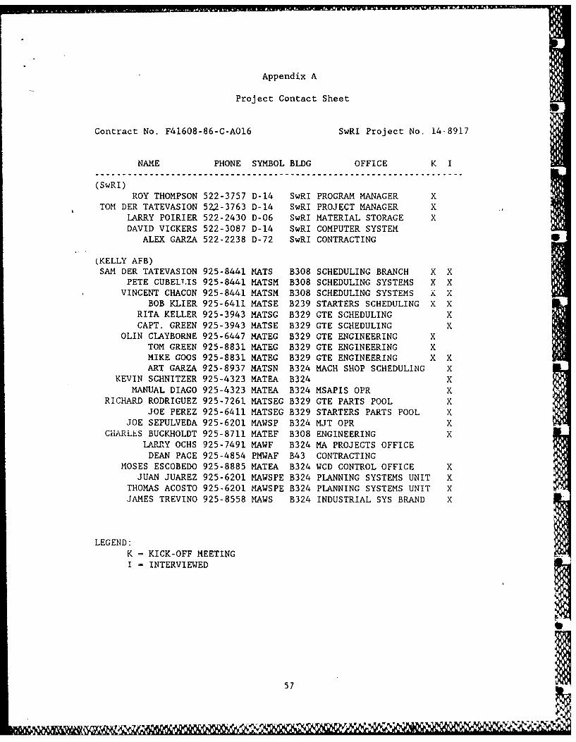
Appendix A
Project Contact Sheet S
Contract No. F41608-86-C-AO16 SwRI Project No. 14-8917
NAME PHONE SYMBOL BLDG OFFICE K I
(SwRI)ROY THOMPSON 522-3757 D-14 SwRI PROGRAM MANAGER X
TOM DER TATEVASION 522-3763 D-14 SwRI PROJECT MANAGER XLARRY POIRIER 522-2430 D-06 SwRI MATERIAL STORAGE XDAVID VICKERS 522-3087 D-14 SwRI COMPUTER SYSTEM
ALEX GARZA 522-2238 D-72 SwRI CONTRACTING
(KELLY AFB)SAM DER TATEVASION 925-8441 MATS B308 SCHEDULING BRANCH X X
PETE CUBELTIS 925-8441 MATSM B308 SCHEDULING SYSTEMS X XVINCENT CHACON 925-8441 MATSM B308 SCHEDULING SYSTEMS X X
BOB KLIER 925-6411 MATSE B239 STARTERS SCHEDULING X XRITA KELLER 925-3943 MATSG B329 GTE SCHEDULING XCAPT. GREEN 925-3943 MATSE B329 GTE SCHEDULING X
OLIN CLAYBORNE 925-6447 MATEG B329 GTE ENGINEERING XTOM GREEN 925-8831 MATEG B329 GTE ENGINEERING XMIKE GOOS 925-8831 MATEG B329 GTE ENGINEERING X XART GARZA 925-8937 MATSN B324 MACH SHOP SCHEDULING X
KEVIN SCHNITZER 925-4323 MATEA B324 XMANUAL DIAGO 925-4323 MATEA B324 MSAPIS OPR X
RICHARD RODRIGUEZ 925-7261 MATSEG B329 GTE PARTS POOL XJOE PEREZ 925-6411 MATSEG B329 STARTERS PARTS POOL X
JOE SEPULVEDA 925-6201 MAWSP B324 MJT OPR XCHARLES BUCKHOLDT 925-8711 MATEF B308 ENGINEERING X
LARRY OCHS 925-7491 MAWF B324 MA PROJECTS OFFICEDEAN PACE 925-4854 PMWAF B43 CONTRACTING
MOSES ESCOBEDO 925-8885 MATEA B324 WCD CONTROL OFFICE XJUAN JUAREZ 925-6201 MAWSPE B324 PLANNING SYSTEMS UNIT X
THOMAS ACOSTO 925-6201 MAWSPE B324 PLANNING SYSTEMS UNIT XJAMES TREVINO 925-8558 MAWS B324 INDUSTRIAL SYS BRAND X
LEGEND:
K = KICK-OFF MEETINGI - INTERVIEWED
57
Appendix B
Initial Survey Checklist
58
%

SOLITHWEST RESEARCH INSTITUTE
GTE/STARTER REPAIR SHOP INITIAL SIRVEY C:HECKLI$::T
PROJECT NO: 14-8.917 Pae 1 ,:, =
CONTRACT NO: F41608-86-C-A016 DATE:_ _
A: INDUCTION (Receiving Items for Repair)
1. Verify shipping documents? ___ YE: ---- NO2. Sign for item(s)? '_ YES .NO3. Los items in? NO
If so, how? /.__
4. Any forms initiated at this Point? _-'YES ---- NOI f so, what forms? _-- --_
----------------- -- - ------ -_
5. Items unpacked & containerized? __ :'__ NO6. Items marked cr tagged at this Point? __-YES _-_NO
I f so, wna t wi th?
7. Items checked for missing components/paits? ---- YES __N0I f so, what doc:umen tat i ,:n?__A! -- _ _
:3. Buffer storage before moving to Disassembl'-?_ _YE= -- N1If so, where? _
9. Items logged out & moved to Disassembly? --- YES=NIHow? By wh o:m'? --------
-- - -- - -- - -- - -- - -- - -- - -- - -- - -- --- - - -
10. Any other action on reception ? - E S'E .If so, List in Remarks.
Remar,.
59
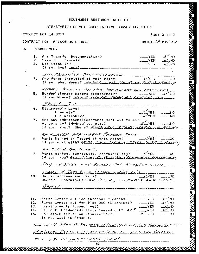
SOUTHWEST RE;EARCH INST I TUTE
GTE/STARTER REPAIR SHOP INITIAL SURVEY CHECKLIST
PROJECT NI. 14-8917 Page 2 oI-:
CONTRACT NO: F4160:3-86-C-AO16 DATE: _____j-
B. DISASSEMBLY
1. AnY Trans Fer Documentation? ... YES kZNO2. Sign for item(s)? ---- YES _-__NOI3. Lcs items in? ---- YES _k,:LNO
IF so, how? ------ -
4. Any forms initiated at this Point? __ S --E--...E NOIf so, what Forms? _ -
5. Buffer storage before disassembly? ---- YES _ _NOI f s,:,, Where? _- cs -
6. Disassembly Levelcomplete? _-YES .... NOSub-assembly? __4._.YES ---- NO
7. Are any sub-assemblies/parts sent out to anyother shop? (H-drauJic, et:.) _Le__YES ---- NOIf s,:', What? Where? - _ . " _ _ _ _ _
r - -- - £ --- S " --"- z-0e- - ---- , -- -E--__---,-S. Parts Marked or Tagged at this Point? --- 'E- NO
If so, what with? / --
9. Parts sorted, segregated, containerized? J .E'I f so, How? - _ _ _i _ ,,_ _ _ _,-
_ _Zzv _EE__ c EforOz Pats Z ____----------..... . . . . ___ _ _ _ k___' .. ..
10. Buffer storage for Parts? _2YE- .. NOWhere? Containers " _.- _
11. Parts Logged oJt for internal :leaning? . YES _
12. Parts Lcgged out for Bld_ 360 (Cleaning)? YE-- _'1:3. Missing Parts logged nut? ----YES J14. Fallout (Co-:,.indemned) Parts logged out? 4/ .€ YES "<N,:15. Anr other action on Di7asse !-.-7 --VE-- NO
If so, List in Remarks.
60_-. .

SOUTHWEST RESEARCH INSTITUTE
GTE/STARTER REPAIR SHOP INITIAL SURVEY CHECKLIST
PROJECT NO: 14-8917 Pase 3 ,f -
CONTRACT NO: F41608-86-C-AO16 DATE:
C. CLEANING (Bldg 329)
1. Any transfer documentation'? --- YES i-tNc.2. Sigsn f .r parts? YES .4 _"
3. Los Parts in? ---- YES _I _NCIf so, how? _J... ----
4. Any -forms ir,itiated at this point? .... Y S _ _OIf so, what forms?- -----------------------------------
5. Buf-fer storage before cleaning? __YE! ---- NOIf so, Where?
6. Parts Cleanings method?
7. Parts marked or tagged at this Point? ____YES __N
If so, what with?- ------------------------------------------
. rts loggsed out of cleanirg? ---- YE' _---NO
9. Buffer storage for irspection? 'YES ---- N_
How? By whom? Where? _ _ _ _ - -- _ __
1). An't- other action o: :1ear, ins? Tl ES .NOIf so, List in Remarks.
REMARKS: ~ -/~f
-'-- -. .... --- ---- - - . . "- "= .... " .....: " ...........-----
], 6/ 61
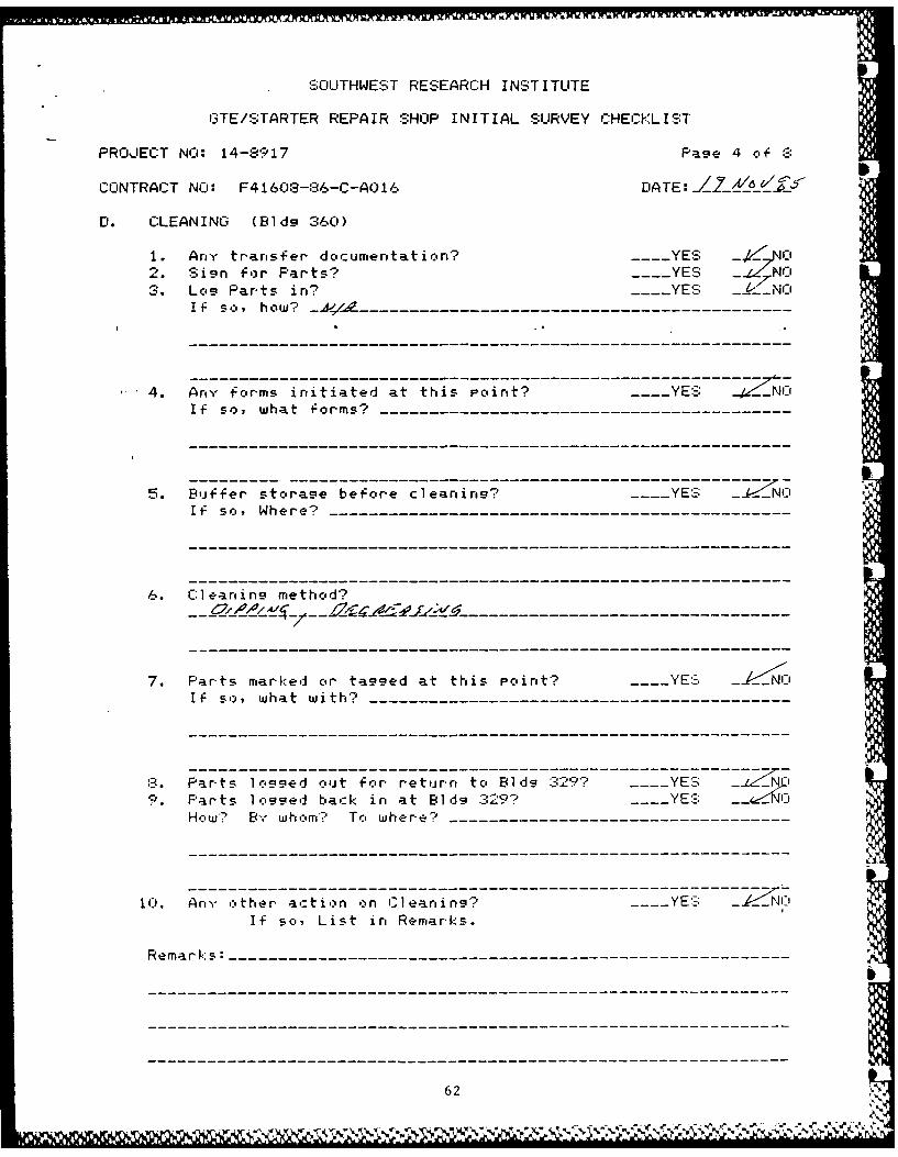
SOUTHWEST RESEARCH I NST ITUTE
GTE/STARTER REPAIR SHOP INITIAL SURVEY CHEC-KLIST
PROJECT NO: 14-8917 Page 4 of
CONTRACT NCO: F4 160:3-86-C-AO 16 DlATE:JZ k
Dl. C:LEANING (Bldg 360)
1. Any transfer do~cumentat ion? ---- YES2. Sig'n for Parts? zE -NO3. Log Parts in? --- YES 1-' NO
If so, how? A---------------------------------------------- ----
4. Any torms initiated at this Point? 1YES
If so, what forms? - - - - - - - - - -- - - - - - - - - - -
5. Buffer stosrage befcore cleaning? -- S -!--'I f so., W here? - - - - - - - - - - - - - - - - - - - - - - -
6. Clearnins method?
7. Parts marked or tagged at this Point? --- YE.= - Ni:,OIf so, what with? - - - - - - - - - -- - - - - - - - - - -
:3. Parts 1logged ouat for return, to Hldg :329? -- S -2~.Parts logge back in at Bldg :329 ? --- YE'- f$ l
How?-: By whom*.n To where?--------------------------------------
1.An)- other act ion -in Cl eansi ng? Y$ __NC
If so, List in Re-marks.
R em ark s : - - - - - - - - - - - - - - - - - - - - - - - - - - - -
62
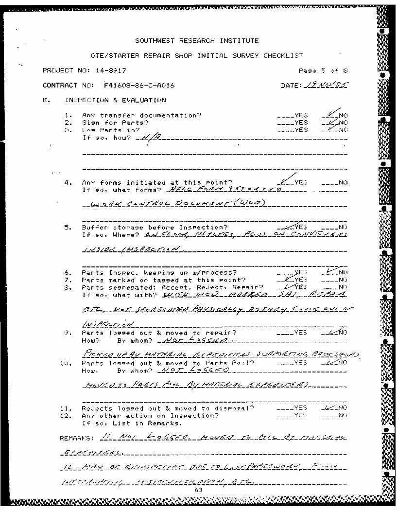
SOUTHWEST RESEARCH INSTITUTE
GTE/.:TARTER REPAIR SHOP INITIAL SLIRVEY C:HEC:KLI S;T
PROJECT NO: 14-:3917 Page 5 o:,- :3
CONTRACT NO: F4160:.-..6-C- AC)16 DATE: _Z___ _
E. INSPE:TION & EVALUATION
I. Anr transfer documentatior? ---- YE* -_2. Sign for Parts? ---- YES ,:3. Log Parts in,? . SYES __CL
If so, how? _. . . . . .-_- -
4. An'-,. forms initiated at this Point? ZYES .. -- NOIf so, what forms? --_-_ . ......
5. Buffer storage before Inspection? _---:Es NOIf so, Where? _g__ __ _ ..- _ _ -/
6. Parts Irspec. keeping up w/Process? . 'S ----<NO
7. Parts marked or tagged at this Point? --YE- N:3. Parts segregated; Accept, Reject, Repair? -ES- NO
If so, what with? J e -_/ J____-----4/-
Z.L,'.l Al_ '
,. Parts 1 ocged out & moved to repair? ... YE'::. 60How? BY whom? _---------------------------
1C). Parts 1,ogged out & moved to Parts Po:.171 ..... YE'- :.Z-How , B, W hom? L---------------------_----
11. Re Jects logged out S( mo:ved to disP,osal. _ .YES <IN12. Anc other action on Inspectiort' - YE:; .. Nu
If so, List in Remarks.
REMARKS: __ .. . .......
----- --- -- -- - - - - - - - -- - - - - - - - -- ------------
--- -- -- - - - - - - - - - - - - - -
63%,%

SC;LITHWEST RESEARC:H INSTITUTE
G'TE/'STARTER REPAIR SHOP INITIAL SURVEY C:HECKLIST .
PROJECT NO: 14-8917 Pae 6 r,':
CONTRACT NO: F4160:3-86-C-A0 16 ///
F. REPAIRS (Bld_ 324)
I. Ary transfer- documertatior,? ---- YES _ _.J _NCi2. Sign for Parts? YE- --- NYE:3. Log Parts in,? ---- YES
If sr" / how:- _ _ -_ _. _ _ _, , . .
4. Ary forms initiated at this Point? ---- YESIf so, what forms?
5. Buffer storage before Repairing? .. ..... NOI f s,:,, Where - -- ---------------------
6. Parts Repaired keeping up with Process? YE'- -7. Parts marked or tagged at this Point? - YE' .....
If so, what with? C----,- -__------
3. Parts logged out For- return to Bls 322? -___YE':__;9. Repaired Parts Fut back into
irspection o p? -- YE- YE': N -IO. Irrepairable or machining error Parts
1,:,_ ed out and set aside for disponsal-' 1¥E:; /_NI11. An,- other actin:r on Repair? _ YE.- : . NO
If so, List in Remarks.
Remarks : _ . / 4 4 / C/9 . . _ . . ,, /.,../' 'C- r . ' .c
;-N64 .'
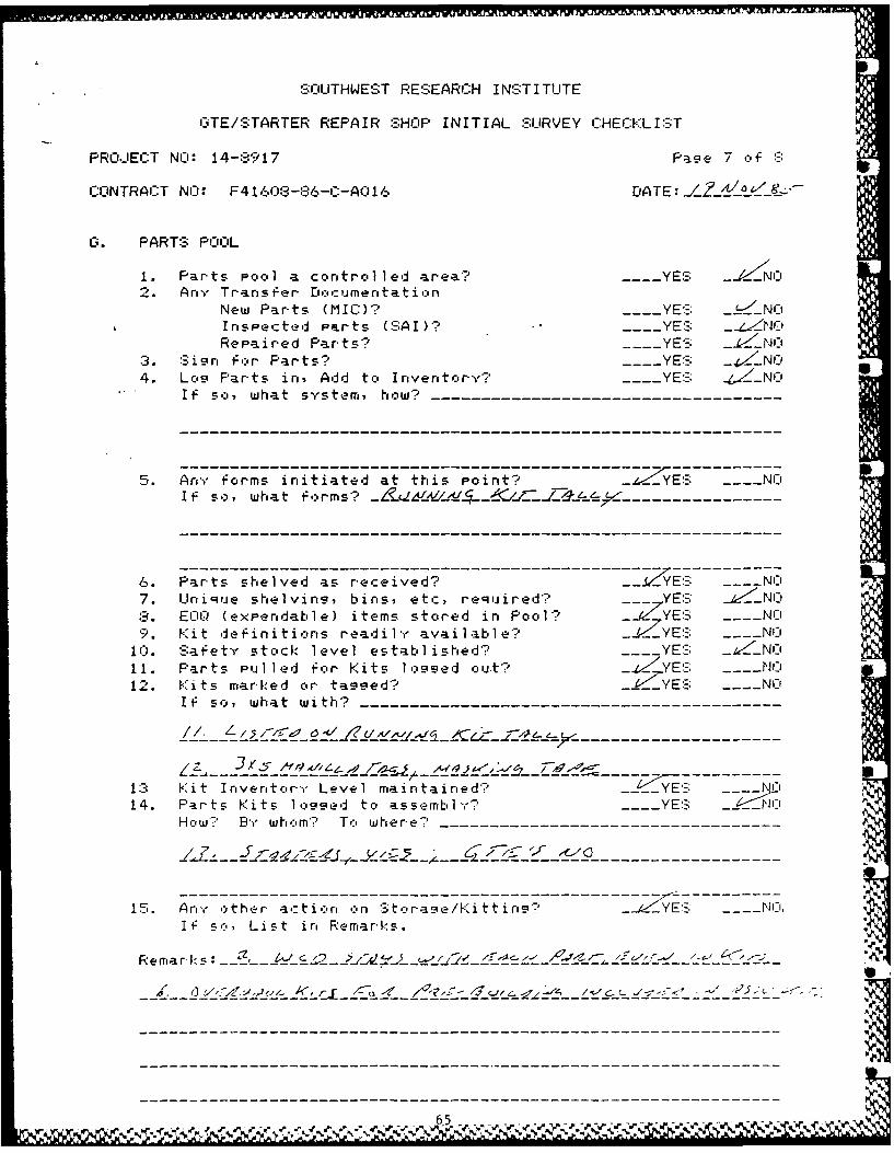
SOITHWEST RESEARC:H INSTITUTE
GTE/STARTER REPAIR SHOP INITIAL SURVEY I::HECKLIST
PRO.JECT NO: 14-:3917 Page 7 of .
CONTRACT NO: F4160-3-86-C-A016 DATE:
G. PARTS POOL
I. Parts Pool a controlled area? .... YES _- N __N2. Ary Transfer Do:,umertation
New Parts (MIC)? YE:-; _uNOInspected Parts (':;AI)? .-- -YES __
Repaired Parts? . .YES _:. NO3. Sign For Parts? -- YE,= __N4. Los Parts in, Add to Inventory? _ YE! =-_NC
I f so, what system, how?
5. Any Forms initiated at this Point? _---YE'. --- NOI if s o, what f ,:,rms? _£ _. --_-__-------------------
6. Parts shelved as received? _k2EE .NO7. Unique shelving, bins, etc, reqJired? NYE- _:3. EC-I-J (expendable) items stored in Pool? __ZYE- ___-N19. Kit definitions readily available? .ZYES ---- Ni
10. Safety stock level established? ---- YE- _wNO11. Parts Pulled for Kits lo ged out? Y Y E ! N.. 112. Kits marked cur tagged? -yE -- N I
If so, what with?
If swawih-----------------------------------
/.............................................. .......
13 Kit Irventor'.- Level maintained? _YF iEI
14. Parts Kits 1 ,:_9sed to assembly? ____YES N
HowY Bw'." hom'? T,:, where?--------------------------------------
15. Ar.,- other ac:tion on St.rae/Kittini? .. Y... Ii,
IF so, List in Remarks.
65 -- - - -
- , --- ' ,-- -----,., ---, r [ - ,- -.4 ----, - --y . ---_-, ------------<, --.-- -_- .-
---------------------------------I--------------------------------
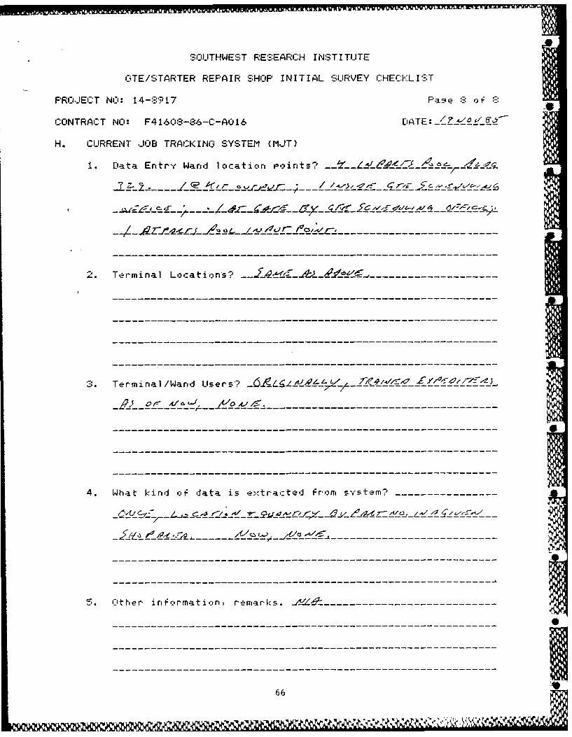
SO'UTHWES;T RESEARCH I NST ITUTE
C-iTE/STARTER REPAIR SHOP INITIAL SUIRVEY C:HECVKL I!S.T
PROJIECT NCO: 14-:3917 P~ :3
C:ONTRACT NCO: F4 1 6(n-86-C:-ACJ16 DATE: _
H. CUJRRENT JOB TRACKING SYSTEM (MJT)
1. Data Entry Wand loicationr Points? L ~~~
Z-9
2. Termi nal Locations? - --- -- --- -
Terminral /Wanud LUsers'? -,
4. What kind of data is extrac~ted from sytm --------
'5. 1ct her inrformat iorn, remarks. -
66

m
Appendix C
Documents Received
Contract No. F41608-86-C-A016 SwRI Project No. 14-8917
1. Drawing, Parts Pool Layout, Present
2. Drawing, Parts Pool Layout, Proposed
3. Drawing, Building 329 Layout, Past
4. Drawing, Building 329 Layout, Present
5. Drawing, Building 329 Layout, Future
6. Drawing, Building 324 Layout, Present
7. Work Control Documents, numerous
8. Metal Tags, Address-o-graph
9. C046 System Transaction Index
10. MAT Parts Flow Diagrams
11. E-G046-01A (MJT) Study Guide/Workbook
12. GTE/Starter Kit Sheets, SAAMA 430
13. MSI/88s Portable Data Terminal Operators Guide
6
67
-s -I . V
Appendix D
Work Control Documents
68
~%
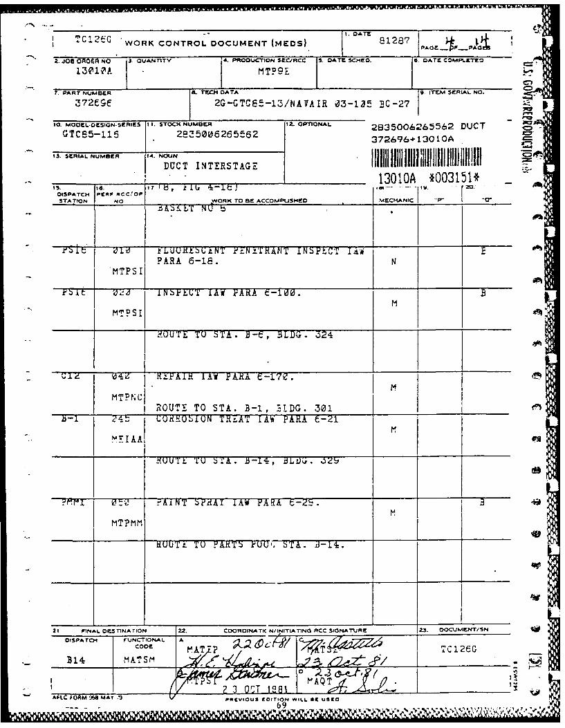
'"Cl 2tC 1. DATE818
SWORK CONTROL DOCUMENT (MEDS) PAG1287 P
2. JOS 0 OER No 3.QUANniTY 4. PR.ODUCTION SEC/RCC 5. DATE SCMED. 6. DATE COMPLETED
13010A M T P 0E
T. PART NUMBER a. Tri DATA .IEMSERIAL NO.
37eE2G-GTCE-r-13/NAYAIR 03-1355 BC-27
10. MODEL-OESIGN. SERIES 11. STOCK NUMBER tZ. OPTIONAL 3OO256DUT.GTC85-116 2835006265562 26+10A
13. SERIAL NUMBER 11.NOUN
DUCT INTERSTAGE130A*35* -
NO W~~~ORK To BE ACCOMPLISHED MCAII*
7StE- i f LUCHLZ)UiNT iPiNIZRAt1T INSPt.Cl Ili*
kZ tST -Zid lNbPEUT lAW PARA t-100.B
Ii4.U'1'I TU STA. B-6, BLDG. 324
17[w24 R. FAIR I AW PARA C-170 .M
MT PNCjAOUTTE TO STA. B-1, 'ZLDG. 301___________
214-- ( COR±HO~iIN TH:LAT IAW PARA E-21
R~uUT1. To ).A B-14, BLIjX. 6
'M 0t G OA NT 5e.A I LAW 7X A 3
MT PMM
kiUUTL TO tFART5 k'U' 5TA. A3-14.
2l FINAL DESTINATION U. COOROINATK N/INITIATING ACC SIGNATURE 123. 0OCJMENT/SN
DISPATOIt FUNCTIONAL A 77* T16
B 14 AS
MAQT~ Y4__________ ~2 3 OCT 1281 ___________________
S A111C FOAM 95B MAY 'v PREVIOUS EDITION WILL ME U990
69

---- ~~~~~~--- -- ------------------- - --- -- -- -- -- -- -- ---------.
I TA726Y * WORK CONTROL DOCUMENT 1.DATE 84145 PAGE 1 OF 1 PAGES1-********************----------------------------------------- ---
12.ORIG/PROD NR 13.QUANTITT 14.PROD SECTION/RCC 15.DATE SCHED 16.DATE COMP II 13255A I I MTPG9E I I
I------------------ - ------------------------ - -------------------------------17.PART NUMBER 19.ITEM SERIAL NR 18/12.TECH DATA/OPTIONALI 37E102-10 I I 2G-GTC35-3I -----------------------------------------I 2v-GTC85-33-6IIe.MOEEL/DESIGN/.SERIESI11.STOCK NR II GTCE5-70A I 2835008691850 1I----------------------------------------- II13,MISCII4.NOUN/END ITEM NOUN II I SPACER SETI--------- (74, FIG. 4-17) -------- ---------I15.DISP-.PD/---------------------------------------------------------ISTATIONIOP 0NO. 11?.WORK TO.BE ACCOMPLISHED 18.IECHI1S"P 29 ,
I-----I ------- I-------------------------------.--------------I---I---I I ESEC 13I ITEM 20
'II SAAMA FORM 430I------I-----------------------------------------------------I------
i Psi I 0e5 I MAGNETIC PARTICLE INSPECT IAWI IMTPSI I WP e05 Oe. N
*I~~ ---1--------I -------------------------------------- I--------I-- --I PSIE I Ole I VISUALLY INSPECT IAW WP 004 OZ I
I IMTPSI .I M II------------I-------------------------------------I----------
I PSI6 1 020 1 INSPECT DIMENSIONALLY IAW WP 004 00 I ,.IMTPSI IM ISI ------- -------------------------------------- -------
1 PS16 I 030 I CORROSION TREAT, OIL DIP IAW II IMTPSI I T. 0. 2-1-11 M I
I---- I--------I ------------------ ------ ------------------ -------- r--1 B14 1 040 1 PARTS POOL
I IMATSE I
-------- I-------- 1 .............. 41--------1I------I---MATEAA13JUN 1984
I I MTPSI j JUN 1 3 1984
MATSEMAQ T
' I I I
1 I I I I I II
-. ,,, ,,; - ,
I ~~~ VI~A L A.II

.1 TA223G * WORK CONTROL DOCUMENT *1.DATE 84304 PAGE 1 OF 1 PAGES I*-------*************------------------------------------------------------ *
12.OBIG/PROD NR 13.QUANTITT 14.PROD SECTION/RCC 15.DATE SCHED 16.DATE COMP I1I 13 123A I - I MTPG9E I I II --- ----------------------------- -------------------------------- -
17.PART NUMBER 19.ITEM SERIAL NR 18/12.TECH DATA/OPTIONAL1 3810036-1 I 1 2G-GTCP36-3I ------------------------------- -- I1e.MOLEL/DESIGN/SERIIESI1l.STOCK NRl I II GTCP36-50 1 2835010123204 II -------------------- ------- --- -- I113.MISCI14.NOUN/IND ITEM NOUN II
II HOUSING INLET BSK #9 1I-------- (85 FIG 3-3)----------------------------------------------- II15.1rISP-16.PDN/------------------- ------------------------------------------- IISTATfON lOP NO. I17.WORK TO tE ACCOMPLISiiI; - 118.MEC9119"P-120 "*Q? II -------- I -------- I ------------------------------------- I--------I--I PSI6 1 010 1 VISUALLY INSPECTI1 1 II IMTPSI I IAW PARA 5-64.1 AND 2 1 M I I I
--------- -- ----------------------------------- I--------------1 1. 020 1 LIMENSIONALLY INSPECTI I II I I lAW FIG 5-15 AND PARA 5-64.3 1 .M I I I
I--------------I ---------- ------ -.---------------I I1 030 1 REPAIR BURRS, MINOR GALLINGl.II I IAW PARA 5-113 AND 5-144 IM I
1---I--------------- ---------------- I--------I--1 040 1 PERFORM CIRCULAR RUNOUT I I I I
I IlAW PARA 5-64.4.5 IM I I-l------------------------- ---------- I ---------- I---
1 050 1 PERFORM MAGNETIC PARTICLE I *I. I II II INSPECTION. I N
I I AW PARA 5-13 AND 5-54.6 1 1I------------------- -------------------- I --------I--
I PS16 1 060 1 REPLACE COMPRESSOR INLET I I I II MTPSI I HOUSING IF INSPECTION REQUIREMENTS I m I., I III I ARE NOT MET. lAW PARA 5-64.? I -t I I
I I I ~ROUTE TO PARTS POOLII I I------------------------- -- --------------- I-------------
I I I MATEA_ ifMI I
I MAQT_ 3198
I I MT SI .1 1
- -- - - - - -- - - -- - -- - - -- - - -- - - -- - -- - - -- - - -- - -
Appendix E
Bldg 329 Systems Implementation Plan
Contract No. F41608-86-C-A016 SwRI Project No. 14-8917
DATE SYSTEM TITLE
28 MAY 86 + Partial installation of MSAPIS (hosts, laser, 4 sta)
25 SEP 86 + MSAPIS inspection system installation complete
01 OCT 86 * Move elect/sheet metal shops out of new PP area
05 JAN 87 * Move disassembly to new area
05 MAR 87 * Relocate PP into new area
01 APR 87 * Procure new cleaning line
10 JUN 87 * Install auto inspection stations
01 JUL 87 * BlB starter workload (13,438 sq ft)
LEGEND:
+ Dates received from Manual Diago, MATEA
* Dates received form Mike Goos, MATEG
72
.0
Appendix F
Parts Pool Layout Drawings
73

CaD Im z
0:0
- 74
CL
Q < a-
z,
> <~
022
C)p 0!
m - -O
75

z L
tce
<<
0
LL
(L C3
< <
u- X -
76, -'
m MOWN
w I
mF L
CL < Czi
C__ M Lz< ) 4
_jC:.> c.
5i
U- Of -,
77z
4 WAK t,1: I! - 4 t

17
- -14.
<" 4.? /, .-
ii
" +I '... 2
F '
- m_- uj
r
-U -. - ----------
-~ _ _ _ _ _ __78
!IL-71:1
.1 <
z I
3r
+ 4.
56 •
.+ - -r IT1 - ,,
+- I
793
A 'a
HI "I

L -tA
zz
j j
I-
P& D
-I.-+~ +
8+ 0
- U t.P' Sto .:Lw~- -
ABBREVIATIONS'
S
AFLC Air Force Logistics Command
ALC Air Logistics Center
AMAD Aircraft Mounted Accessory Drive
AS/RS Automated Storage/Retrival System
AWM Awaiting Maintenance
AWP Awaiting Parts
B-Job Partial Overhaul Job
BOM Bill of Material
CDRL Contract Data Requirements List
CGB Central Gearbox
CID Carousel Interface Device
CPU Central Processing Unit
CRT Cathode Ray Tube (Computer Terminal)
DMICS Depot Maintenance Integrated Communications System
DOD Department of Defence
DS Directorate of Distribution
DSS Decision Support System
D033 Base Supply Data System
DWC Digital Weight Counter
E/lI Evaluation/Inspection Shop
FPI Flourescent Penetrant Inspection
GTE Gas Turbine Engine
G046 MJT Data System Designation
GOO4L MA Work Order Data System
HHLS Hand Held Laser Scanner
81
lAW In Accordance With
I/0 Input/Output
JFS Jet Fuel Starter
JON Job Order Number
LCB Load Cell Base
LM Directorate of Logistics Management
LOGMARS Logistics Application of Automated Marking & Reading Symbols
MA Directorate of Maintenance
MAB Aircraft Division
MAE Engine Division
MAT Technology Repair Division
MAW Resources Management Division
MCS Material Control System
MDS Model/Design/Series
MIC Material Inventory Control
MIS Management Information System
MJT Maintenance Job Tracking
MPI Magnetic Particle Inspection
MSAPIS Multi-Station Auto Prompting Inspection System
NSN National Stock Number
0CM On Condition Maintenance
OPD Obvious Physical Damage
OPR Office of Primary Responsibility
OWO On Work Order
PC Personal Computer
POC Point Of Contact
PP Parts Pool
:2

P/N Part Number
RCC Resource Control Center
RID Robotic Interface Device
SA-ALC San Antonio-Air Logistics Center
SAI Satisfactory As Is
SOW Statement of Work
S/R Storage/Retrival
SPS Secondary Power System
S/N Serial Number
SwRI Southwest Research Institute
TO Technical Order
TWS Tote Weighing System
WCD Work Control Document
WIP Work In-Process
WSL Work Station/Lift
83

w w w w w w w w w w 9