Embed Size (px)
Citation preview
STUDY OF BEHAVIOR OF GRILLAGESIN ELASTIC AND PLASTIC RANGES
byThein Wah
Robert Sherman
FINAL REPORT
Contract No. N00024-67-C-5356Project Serial No. S-F013 C3 01 Task 2050
SwRI Project No. 03-2101-01
for
Naval Ship Systems Command
Department of the NavyWashington, D. C. 20360
Distribution of the Document Is Unlinjtec. ,
December 1, 1969
R SOUTHWEST RESEARCH IN ST IT U TESAN ANTONIO HOUSTON
Rrprodu(cd rv
CLE AR INGHOUSEfor F der li Scwnt,o N le-.hr,c
lnforrm)on 1 , Va 2215
V
STUDY OF BEHAVIOR OF GRILLAGESIN ELASTIC AND PLASTIC RANGES
byThein Wah
Robert Sherman
FINAL REPORT
Contract No. N00024-67-C-5356
Project Serial No. S-F013 C3 01 Task 2050
SwRI Project No. 03-2101-01
This docmfleft hmsbe
for D DD CNaval Ship Systems Command ,
Department of the Navy NOVWashington. D. C. 20360
,, Lt.... --." " w U., Lim....,
Distribution of the Document Is Unlimited
December 1, 1969
Approved:
Robert C. DeHart, Director
Department of Structural Research
ABSTRACT
This report is concerned with an experimental evaluation of tI-e
behavior of plated grillages under the simultaneous action of a uniform
normal pressure and axial compression. The combination of loads was
gradually increased so as to produce large plastic deformation, the aim
being to obtain an estimate of the collapse strength of the grillage.
The test procedure is described and conclusions are drawn regard-
ing the behavior of the longitudinals, the transversals, and the plating.
Difficulties in the tests arising from local crippling of the stiffeners are
also discussed.
I
!'.1 "
TABLE OF CONTENTS
.1 PageLIST OF FIGURES iii
LIST OF TABLES v
I. INTRODUCTION 1
III DESCRIPTION OF TESTS 3
A. Test l(a) 10
B. Test l(b) 15
C. Test 1(c) 21
III. ANALYSIS OF RESULTS 27
IV. CONCLUSIONS 47
APPENDIX A - OUTLINE OF A RECOMMENDED PROGRAM A-I
2 !'
'11
iimi
LIST OF FIGURES
Page
FIGURE 1. SKETCH OF THE GRILLAGE TEST FACILITY 4
FIGURE 2. GENERAL VIEW OF TEST RIG WITH TOP COVERREMOVED 6
FIGURE 3. END DETAIL OF TRANSVERSE MEMBERS SHOW-
ING "CROW'S FEET" AND HOLD-DOWN BARADDED PRIOR TO TEST l(a) 7
FIGURE 4. THE GRILLAGE SPECIMEN UNDERGOING TEST 8
FIGURE 5. SKETCH OF GRILLAGE SPECIMEN 9
FIGURE 6, STRAIN GAGE AND DIAL GAGE LOCATIONS FORTEST 1 11
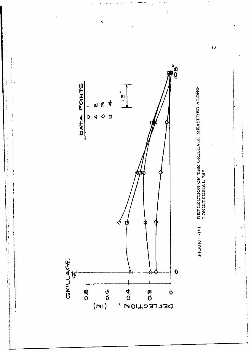
FIGURE 7(a). DEFLECTION OF THE GRILLAGE MEASUREDALONG LONGITUDINAL "B" 13
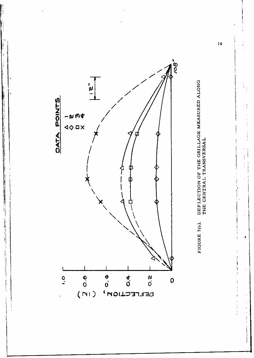
FIGURE 7(b). DEFLECTION OF THE GRILLAGE MEASUREDALONG THE CENTRAL TRANSVERSAL 14
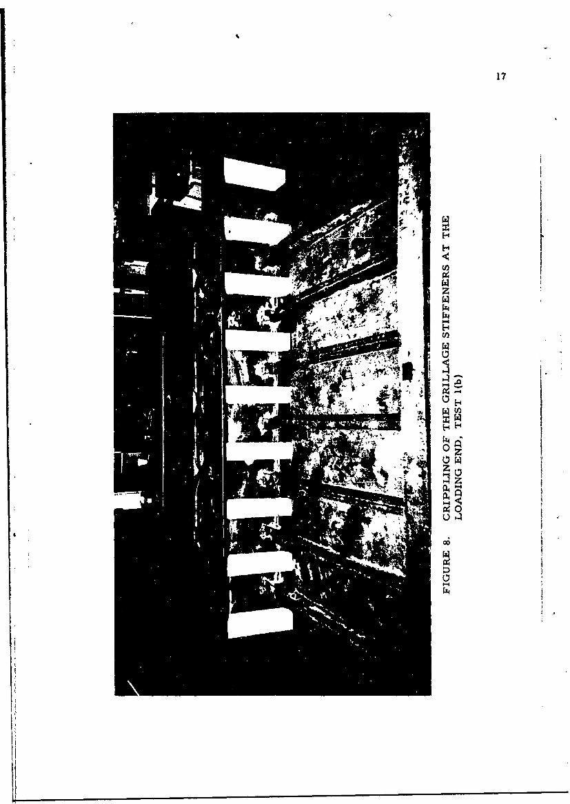
FIGURE 8. CRIPPLING OF THE GRILLAGE STIFFENERS ATTHE LOADING END, TEST l(b) 17
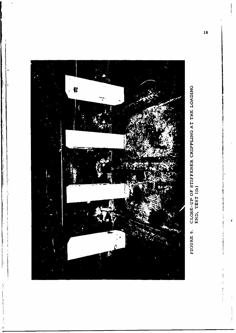
FIGURE 9., CLOSE-UP OF STIFFENER CRIPPLING AT THELOADING END, TEST l(b) 18
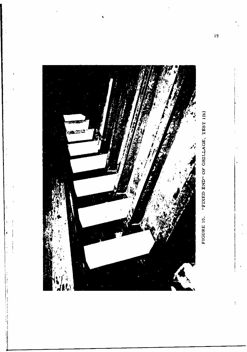
FIGURE 10. "FIXED END" OF GRILLAGE, TEST l(b) 19
FIGURE 11. RIPPLE IN FLANGE AT SECOND PANEL FROMLOADING END, TEST l(b) 20
FIGURE 12. CRIPPLING AT THE LOADING END AFTERTEST 1(c) (NOTE THE CONFIGURATION OF THEEND STIFFENERS) 22
FIGURE 13. THE FIXED END, TEST 1(c) 23
FIGURE 14. LOADING END AFTER TEST 1(c) 25
iv
I [.
I%
LIST OF FIGURES (CONT'D)
Page
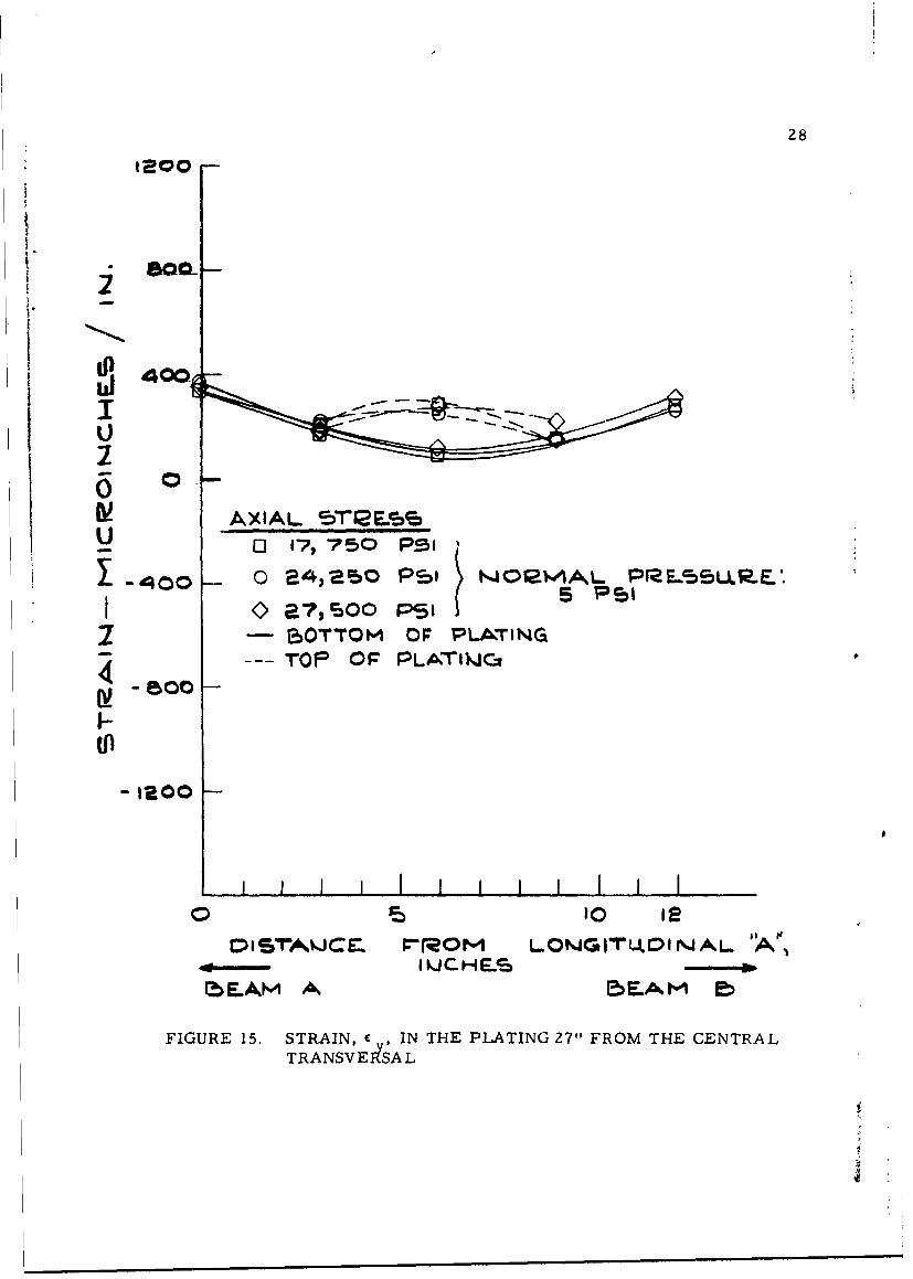
FIGURE 15. STRAIN, c y, IN THE PLATING 27" FROM THECENTRAL TRANSVERSAL 28
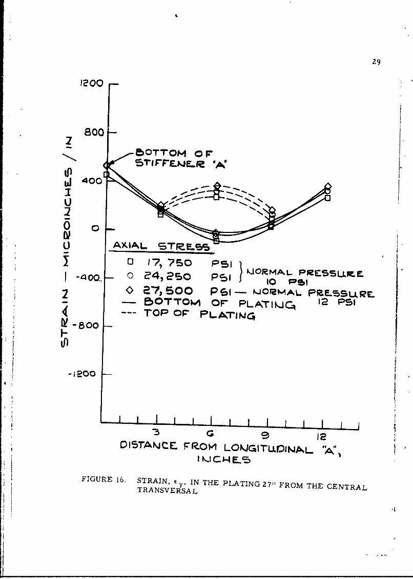
FIGURE 16. STRAIN, E y, IN THE PLATING 27" FROM THECENTRAL TRANSVERSAL 29
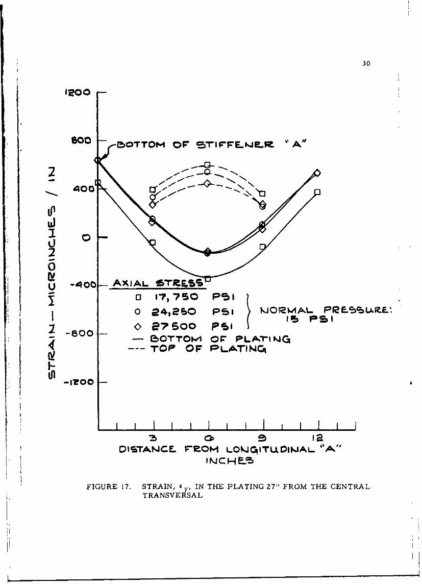
FIGURE 17. STRAIN, E yo IN THE PLATING 27" FROM THECENTRAL TRANSVERSAL 30
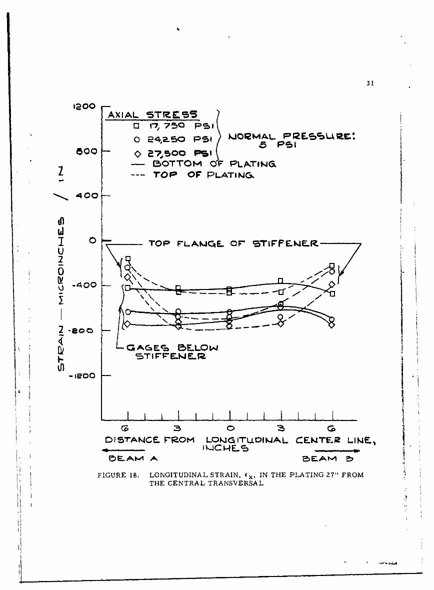
FIGURE 18. LONGITUDINAL STRAIN, ex, IN THE PLATING27" FROM THE CENTRAL TRANSVERSAL 31
FIGURE 19. LONGITUDINAL STRAIN, cx, IN THE PLATING27" FROM THE CENTRAL TRANSVERSAL 32
FIGURE 20. LONGITUDINAL STRAIN, ex, IN THE PLATING27" FROM THE CENTRAL TRANSVERSAL 33
FIGURE 21. LONGITUDINAL STRAIN, Ex, IN THE LONGITUDI-NAL "A" 27" FROM THE CENTRAL TRANSVERSAL 37
FIGURE 22(a). LONGITUDINAL STRAIN, cx, IN THE LONGITUDI-NAL "A" 27" FROM THE CENTRAL TRANSVERSAL 39
FIGURE 22(b). LONGITUDINAL STRAIN, ex, IN THE LONGITUDI-
NAL "A" 18" FROM THE CENTRAL TRANSVERSAL 40
FIGURE 23(a). STRAIN IN THE CENTRAL TRANSVERSAL 27"FROM THE GRILLAGE EDGE 42
FIGURE 23(b). STRAIN IN THE CENTRAL TRANSVERSAL AT THEGRILLAGE CENTERLINE 43
FIGURE 24(a)., STRAINS IN THE CENTRAL TRANSVERSAL 27"FROM THE GRILLAGE EDGE 44
I FIGURE 24(b). STRAINS IN THE CENTRAL TRANSVERSAL AT THEGRILLAGE CENTERLINE 45
FIGURE 25(a). INSTRUMENTATION PLAN FOR PROPOSEDSPECIMENS 2, 3 AND 4 A-7
FIGURE 25(b). STRAIN GAGE KEY A-8
v
• V.
I

LIST OF TABLES
Page
TABLE I. TEST NO. 1(a) 12
*TABLE II. TEST NO. 1(b) 16
TABLE III. TEST NO. 1(c) 26
vii
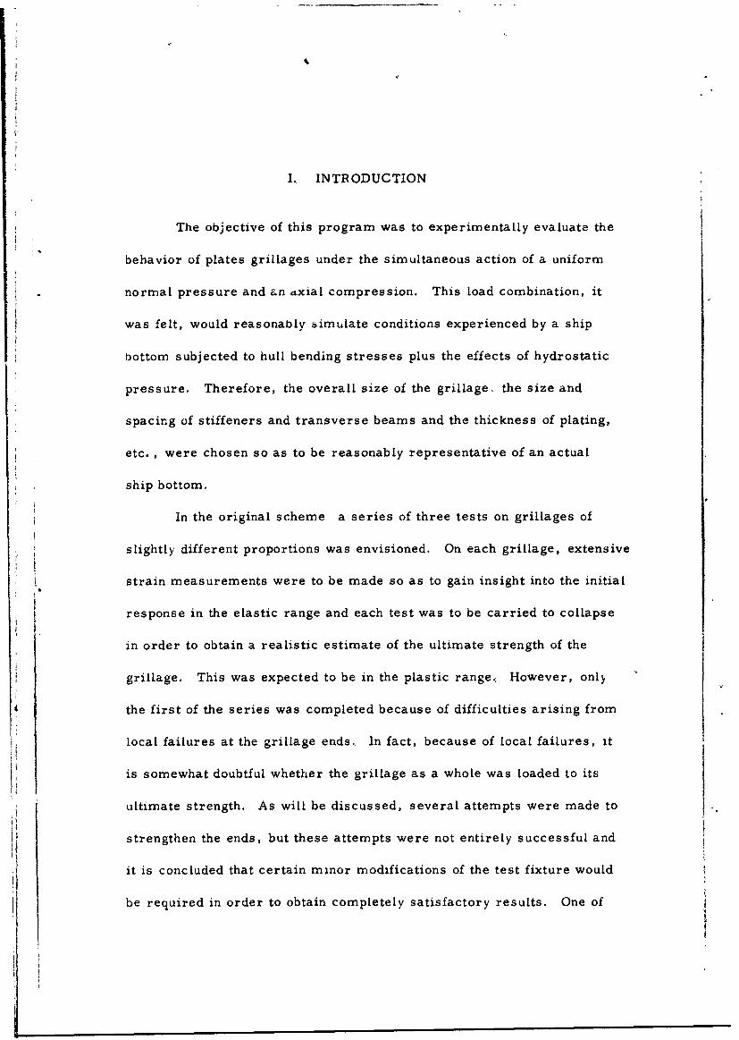
I., INTRODUCTION
The objective of this program was to experimentally evaluate the
behavior of plates grillages under the simultaneous action of a uniform
normal pressure and an axial compression. This load combination, it
was felt, would reasonably simulate conditions experienced by a ship
bottom subjected to hull bending stresses plus the effects of hydrostatic
pressure. Therefore, the overall size of the grillage. the size and
spacing of stiffeners and transverse beams and the thickness of plating,
etc. , were chosen so as to be reasonably representative of an actual
ship bottom.
In the original scheme a series of three tests on grillages of
slightly different proportions was envisioned. On each grillage, extensive
strain measurements were to be made so as to gain insight into the initial
response in the elastic range and each test was to be carried to collapse
in order to obtain a realistic estimate of the ultimate strength of the
grillage. This was expected to be in the plastic range., However, only
the first of the series was completed because of difficulties arising from
local failures at the grillage ends., In fact, because of local failures, it
is somewhat doubtful whether the grillage as a whole was loaded to its
ultimate strength. As will be discussed, several attempts were made to
strengthen the ends, but these attempts were not entirely successful and
it is concluded that certain minor modifications of the test fixture would
be required in order to obtain completely satisfactory results. One of
2
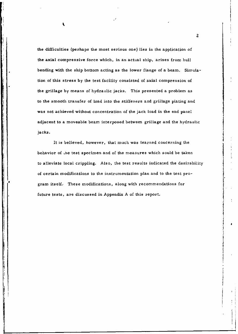
the difficulties (perhaps the most serious one) lies in the application of
the axial compressive force which, in an actual ship, arises from hull
bending with the ship bottom acting as the lower flange of a beam. Simula-
tion of this stress by the test facility consisted of axial compression of
the grillage by means of hydraulic jacks. This presented a problem as
to the smooth transfer of load into the stiffeners and grillage plating and
was not achieved without concentration of the jack load in the end panel
adjacent to a moveable beam interposed between grillage and the hydraulic
jacks.
It is believed, however, that much was learned concerning the
behavior of he test specimen and of the mea3ures which sould be taken
to alleviate local crippling. Also, the test results indicated the desirability I
of certain modifications to the instrumentation plan and to the test pro-
gram itself. These modifications, along with recommendations for
future tests, are discussed in Appendix A of this report. II
I
I
3
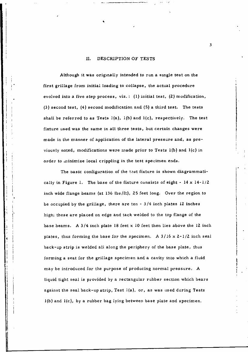
II. DESCRIPTION OF TESTS
Although it was originally intended to run a single test on the
first grillage from initial loading to collapse, the actual procedure
evolved into a five step process, viz. : (1) initial test, (2) modification,
(3) second test, (4) second modification and (5) a third test. The tests
shall be referred to as Tests 1(a), l(b) and 1(c), respectively. The test
fixture used was the same in all three tests, but certain changes were
made in the manner of application of the lateral pressure and, as pre-
viously noted, modifications were made prior to Tests l(b) and l(c) in
order to aiinimize local crippling in the test specimen ends.
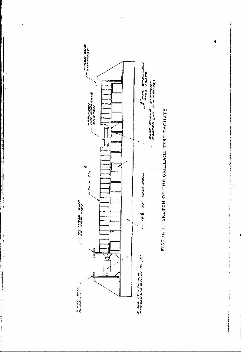
The basic configuration of the tst fixture is shown diagrammati-
cally in Figure 1. The base of the fixture consists of eight - 14 x 14-1/2
inch wide flange beams (at 136 lbs/ft), 25 feet long. Over the region to
be occupied by the grillage, there are ten - 3/4 inch plates 12 inches
high; these are placed on edge and tack welded to the top flange of the
base beams. A 3/4 inch plate 18 feet x 10 feet then lies above the 12 inch
plates, thus forming the base for the specimen. A 3/16 x 2-1/2 inch seal
back-up strip is welded all along the periphery of the base plate, thus
forming a seat for the grillage specimen and a cavity into which a fluid
may be introduced for the purpose of producing normal pressure., A
liquid tight seal is provided by a rectangular rubber section which bears
against the seal back-up strip, Test 1(a), or, as was used during Tests
1(b) and 1(c), by a rubber bag lying between base plate and specimen.
F.1
~~6-4if
7
4
I QZ4
The two ends of the fixture are closed by 30 inch -beams, one of which
is moveable and forms the end at which the axial compression is applied;
the opposite er].f"d. The two longitudinal sides are closed by
stiffened side channels which bolt through the specimen to the 3/4 inch
base plate. Longitudinal motion is made possible by cutting 3 inch slots
in the specimen, thereby allowing relative motions between the test
grillage and the 3/4 inch base plate and side channels.
After the grillage specimen is placed inside the fixture, the entire
top is covered by a 1-1/2 inch plate bolted with shoulder bolts to the top
flanges of the 30 inch I-beams. This plate is sized to ensure that the
axial Load is reacted equally between base beams and cover plate. The
axial load is applied by five 8 inch diameter hydraulic cylinders capable
of exerting a total of about 1,500,000 pounds at a jack pressure of
6,000 psi.
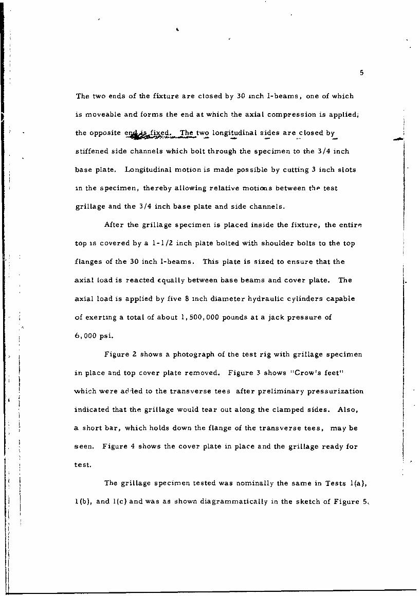
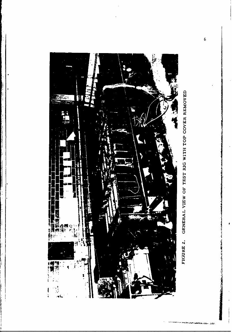
Figure 2 shows a photograph of the test rig with grillage specimen
in place and top cover plate removed. Figure 3 shows "Crow's feet"
which were adied to the transverse tees after preliminary pressurization
indicated that the grillage would tear out along the clamped sides. Also,
a short bar, which holds down the flange of the transverse tees, may be
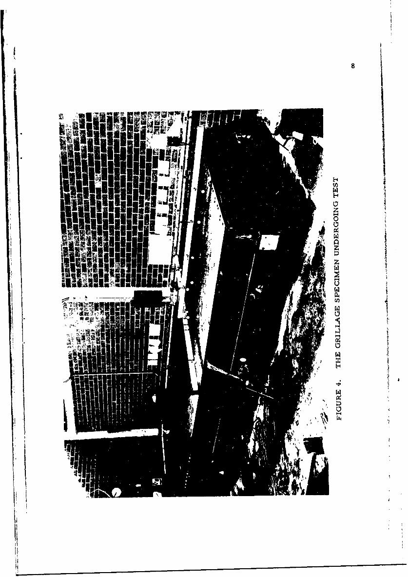
seen. Figure 4 shows the cover plate in place and the grillage ready for
test.
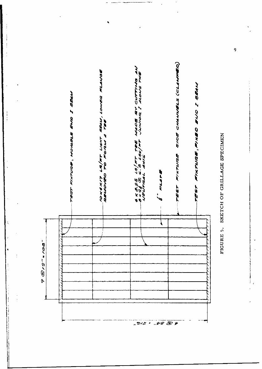
The grillage specimen tested was nominally the same in Tests l(a),
1(b), and l(c) and was as shown diagrammatically in the sketch of Figure 5.
6
U I
H:1C,, 5
H I'Li I
I1111 1! ~I I
'4
IIii *
N
t
4
I! ,I
I
7
0i
O0
> ,
0
c00
1 8r
I * q"momeTA~iI~ps
InI
Iil
91''3 a
'4
Ii
I~J
'4 Q
'4Ii'Ii zQ
Zi~ U0 4 ii.
P.,(12
'I 1%I'
'4q.J
'11%LN NV)
UH
1(12
I __
0_____ ______ K____ ______ ~Z4
I,
__________ I ______________I ______________ ______________
K__ I'I
10
A. Test 1(a)
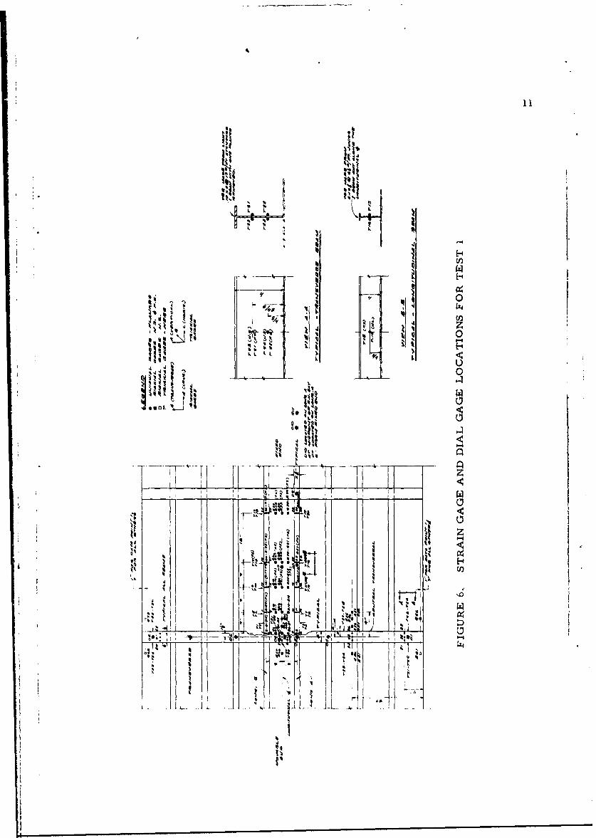
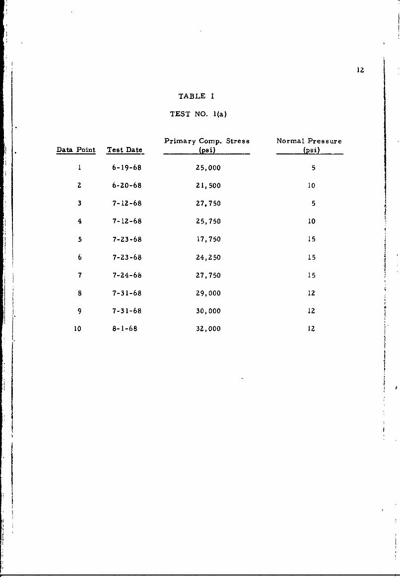
Test 1(a), the only completely instrumented test, had a total of
302 strain gages, plus several Ames dial gages, located as shown in
Figure 6. During test, strain and deflection readings* were taken for
ten separate combinations of axial compressive stress and normal pres-
sure which result from design curves currently in use at the Naval Ship
Systems Command. These combinations are given in Table I where they
are designated as Data Points. During the tests, each Data Point was
obtained by first applying the axial load to the required value, then
gradually increasing the normal pressure while holding the axial load
constant. When the Data Point was reached, strain and deflection read-
ings were taken and recorded. Also, in the case of Data Points 5, 6 and 7,
intermediate readings were taken at values of 1/3 and 2/3 of the required
normal pressure. As will be seen from Figure 4, deflection readings
were obtained along one of the beams near the longitudinal centerline
of the grillage and along the beam which forms the central transversal.
The resultant readings are plotted in Figures 7(a) and (b).
The most severe condition to which the grillage was subjected was
a maximum axial pressure of 32,000 psi with a normal pressure of twelve
psi. At this load the deflections experienced by the grillage were large
enough to cause leakage of the fluid used to exert the normal pressure,
the test was therefore discontinued.
*These readings were reported in a previously submitted document andtherefore, for the sake of brevity and clarity, are not included hereinexcept to the extent necessary for analysis of the resulting data, seeSection III following.
logo$ 1111
* H *
k IN4-±1f
I't4
-" 4 Ci
'I z
-Ar
12
TABLE I
TEST NO. 1(a)
Primary Comp. Stress Normal PressureData Point Test Date (psi) (psi)
1 6-19-68 25,000 5
2 6-20-68 21,500 10
3 7-12-68 27,750 5
4 7-12-68 25,750 10
5 7-23-68 17,750 15
6 7-23-68 24,250 15
7 7-24-68 27,750 15
8 7-31-68 29,000 12
9 7-31-68 30,000 12
10 8-1-68 32,000 12
I.1
13
00
-0I
4
Lix
L5 6o
14
z
07z
0 /4
z
t3
0 /u(NI) NOII:: 731373
15
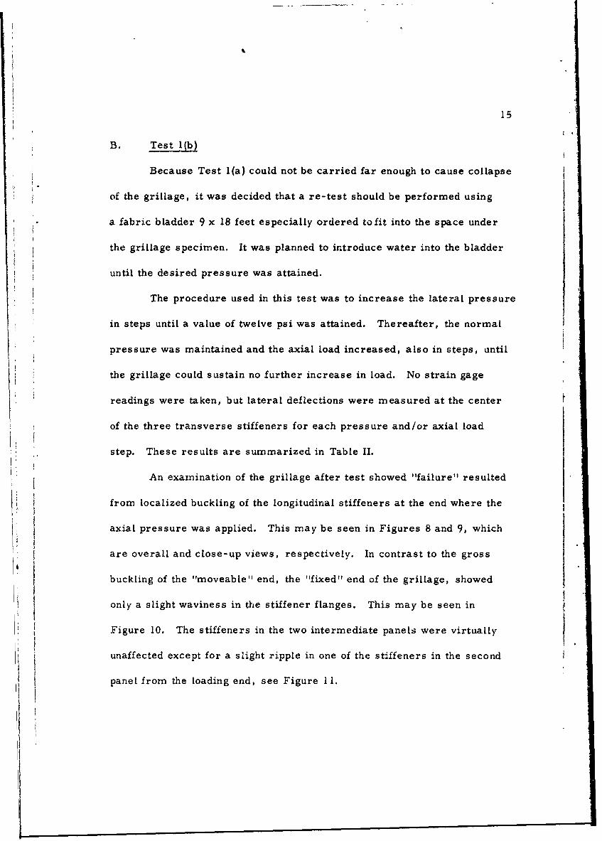
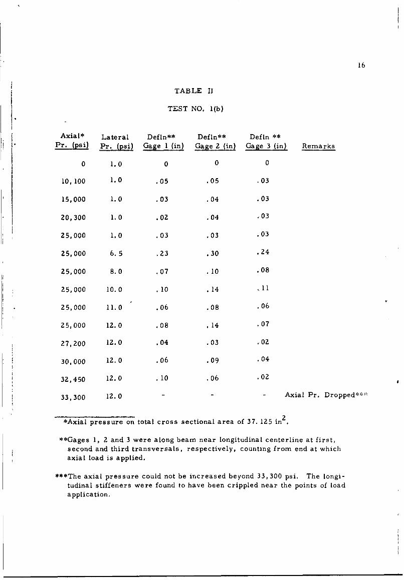
B. Test l(b)
Because Test l(a) could not be carried far enough to cause collapse
of the grillage, it was decided that a re-test should be performed using
a fabric bladder 9 x 18 feet especially ordered tofit into the space under
the grillage specimen. It was planned to introduce water into the bladder
until the desired pressure was attained.
The procedure used in this test was to increase the lateral pressure
in steps until a value of twelve psi was attained. Thereafter, the normal
pressure was maintained and the axial load increased, also in steps, until
the grillage could sustain no further increase in load. No strain gage
readings were taken, but lateral deflections were measured at the center
of the three transverse stiffeners for each pressure and/or axial load
step. These results are summarized in Table II.
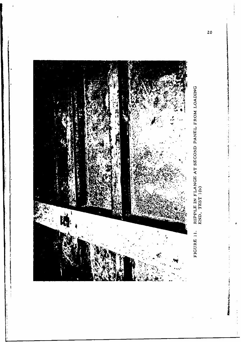
An examination of the grillage after test showed "failure" resulted
from localized buckling of the longitudinal stiffeners at the end where the
axial pressure was applied. This may be seen in Figures 8 and 9, which
* Iare overall and close-up views, respectively. In contrast to the gross
buckling of the "moveable" end, the "fixed" end of the grillage, showed
only a slight waviness in the stiffener flanges. This may be seen in
Figure 10. The stiffeners in the two intermediate panels were virtually
unaffected except for a slight ripple in one of the stiffeners in the second
panel from the loading end, see Figure 11.
__1
16
TABLE II
TEST NO. 1(b)
Axial* Lateral Defln** Defln** DefLn **Pr. (psi) Pr. (psi) Gage I (in) Gage 2 (in) Gage 3 (in) Remarks
0 1.0 0 0 0
10,100 1.0 .05 .05 .03
15,000 1.0 .03 .04 .03
20,300 1.0 .02 .04 .03
25,000 1.0 .03 .03 .03
25,000 6.5 .23 .30 .24
25,000 8.0 07 .10 .08
25,000 10.0 10 .14 .I1
25,000 11.0 06 .08 .06
25,000 12.0 08 .14 .07
27,200 12.0 .04 .03 .02
30,000 12.0 .06 .09 .04
32,450 12.0 .10 .06 .02
33,300 12.0 - - Axial Pr. Dropped,"-'
*Axial pressure on total cross sectional area of 37. 125 in 2 .
**Gages 1, 2 and 3 were along beam near longitudinal centerline at first,second and third transversals, respectively, counting from end at whichaxial load is applied.
***The axial pressure could not be increased beyond 33,300 psi. The longi-
tudinal stiffeners were found to have been crippled near the points of loadapplication.
17
0 rz
0Z4
-0
00
18
IkI
04
'9
I'5, J~I
,, 1/U2
H
xI~z4
II
I
20
IVI#1* 1-
ilk.
21
C. Test l(c)
The results in Test l(b) were considered inconclusive because
overall collapse of the grillage did not occur. Therefore, Test 1(c) was
performed in an attempt to bring about failure in one of both of the two
interior bays. Such a failure mode, it was felt, would be more indicative
of total collapse than was the crippling of the stiffeners in the two end bays.
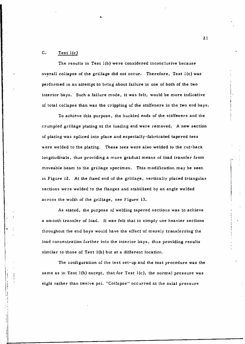
To achieve this purpose, the buckled ends of the stiffeners and the
crumpled grillage plating at the loading end were removed. A new section
of plating was spliced into place and especially-fabricated tapered tees
were welded to the plating. These tees were also welded to the cut-back
longitudinals, thus providing a more gradual means of load transfer from
moveable beam to the grillage specimen., This modification may be seen
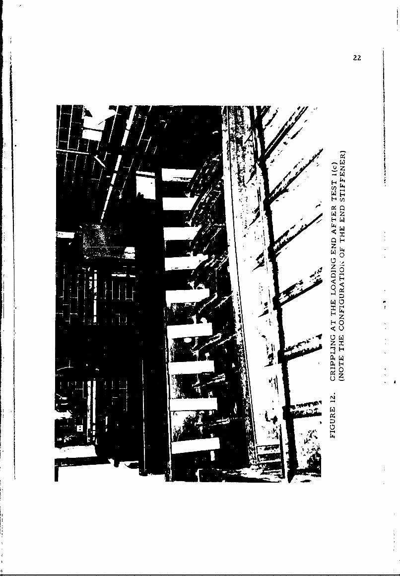
in Figure 12. At the fixed end of the grillage, vertically placed triangular
sections were welded to the flanges and stabilized by an angle welded
across the width of the grillage, see Figure 13.
As stated, the purpose of welding tapered sections was to achieve
a smooth transfer of load. It was felt that to simply use heavier sections
throughout the end bays would have the effect of merely transferring the
load concentration further into the interior bays, thus providing results
similar to those of Test 1(b) but at a different location.
The configuration of the test set-up and the test procedure was the
same as in Test 1(b) except, that for Test 1(c), the normal pressure was
eight rather than twelve psi. "Collapse" occurred at the axial pressure
1
22
. JI
HO4
23
JI~~4~Ej ~
rf~-4
'-4
I
II
24
of 34,600 psi, a value above which the axial load could not be main-
tamined.
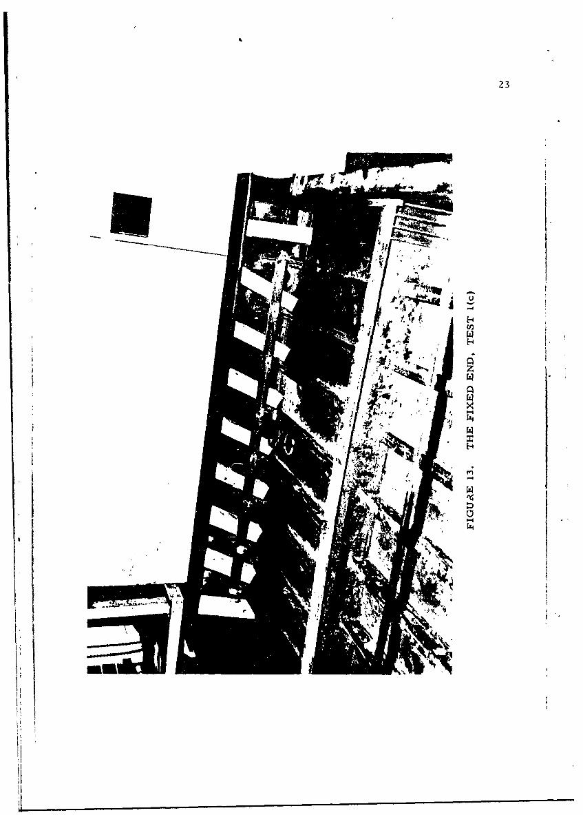
Examination of the grillage after test showed essentially the same
features as in Test 1(b), namely a crippling of the stiffeners at the loaded
end. An overall collapse of the grillage did not occur. At least in part,
this was because of insufficient torsional rigidity within the heavy I-beam
against which the jack pressure is applied. This beam, which is shown
in Figure 14, bent and twisted so that the load was no longer applied at
the center of gravity of the deformed section.
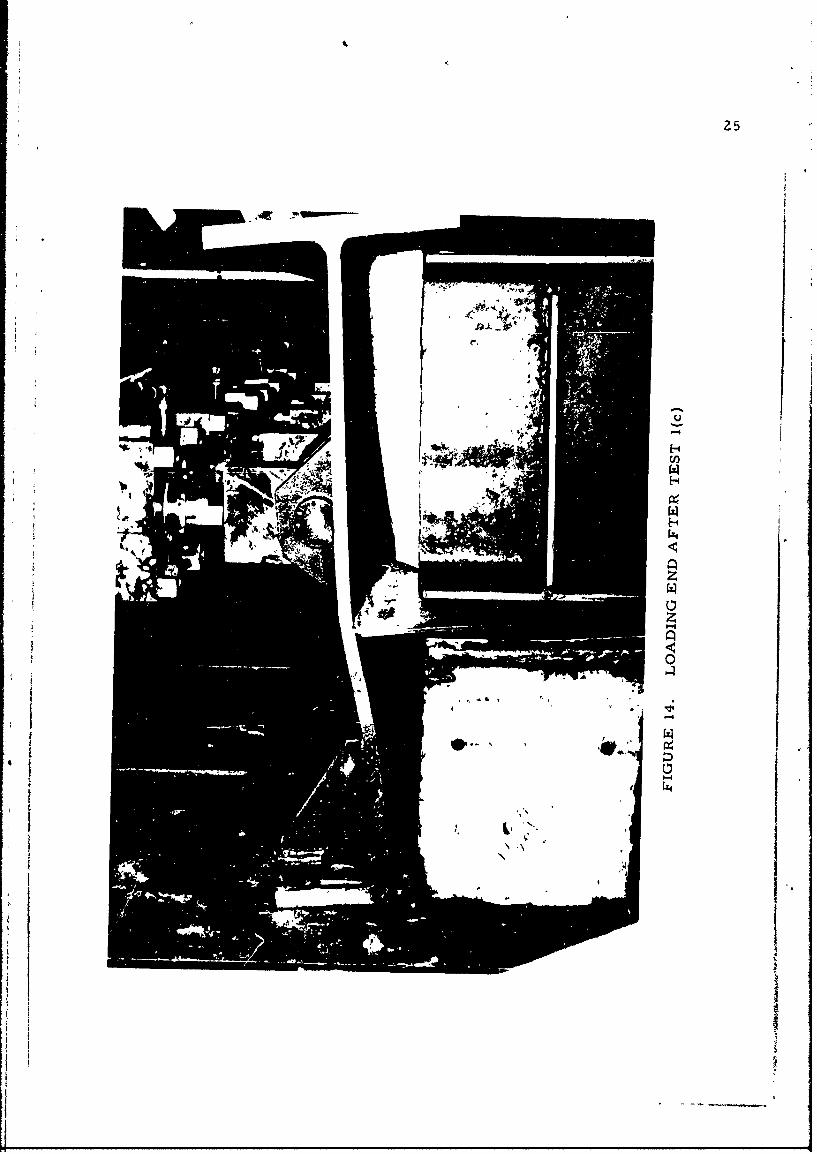
The lateral deflections recorded are tabulated in Table III.
IA
1a
II
U'-4
HU)
1* H
H
F Uz
0
1.If
I
'4
4,
- .'.
t
26
TABLE III
TEST NO. l(c)
Axial* Lateral Defln** Defln* Defln**Pr. (psi) Pr. (psi) Gage 1 (in) Gage 2 (in) Gage 3 (in) Remarks
0 1 0 0 0
10,100 8 0.4375 0.5000 0.3437
15,200 8 0.4688 0.5625 0.3750
20,200 8 0.5000 0.6250 0.3750
25,000 8 0.5625 0.6563 0.4063
27,000 8 0.5625 0.6875 0.4063
30,400 8 0.6250 0.6875 0.4375
32,400 8 0.6250 0.7188 0.4375
34,600 8 - - - Axial Pr.Dropped
*Axial pressure on total cross sectional area of 37. 125 in 2.
**Gages 1, 2 and 3 were along beam near longitudinal at first, second
and third transversals, respectively, counting from end at which axiallead is applied.
27
III. ANALYSIS OF RESULTS
As mentioned in the footnote of Page 10, though extensive strain
data were generated in Test l(a), analysis undertaken herein is confined
to that relating to the overall behavior of the grillage under combined
axial and normal pressure loads. Therefore, only a small portion of the
data is plotted.
All references in Figures 15 to 24 are, with regard to strain gage
location and the designation of stiffeners, according to Figure 6. The
axis "x" is in the longitudinal direction. i.e. , parallel to stiffeners, and
the axis "y" is at right angles to "x". Figures 15, 16 and 17 are plots of
the ey strain at the top and bottom surfaces of the plating and Figures 18,
19 and 20 are plots of the c x strain at the same location. These strain
readings are taken at a transverse section sufficiently far removed from
the central transverse stiffener to avoid the local disturbance in stress
flow produced by the transverse beam.
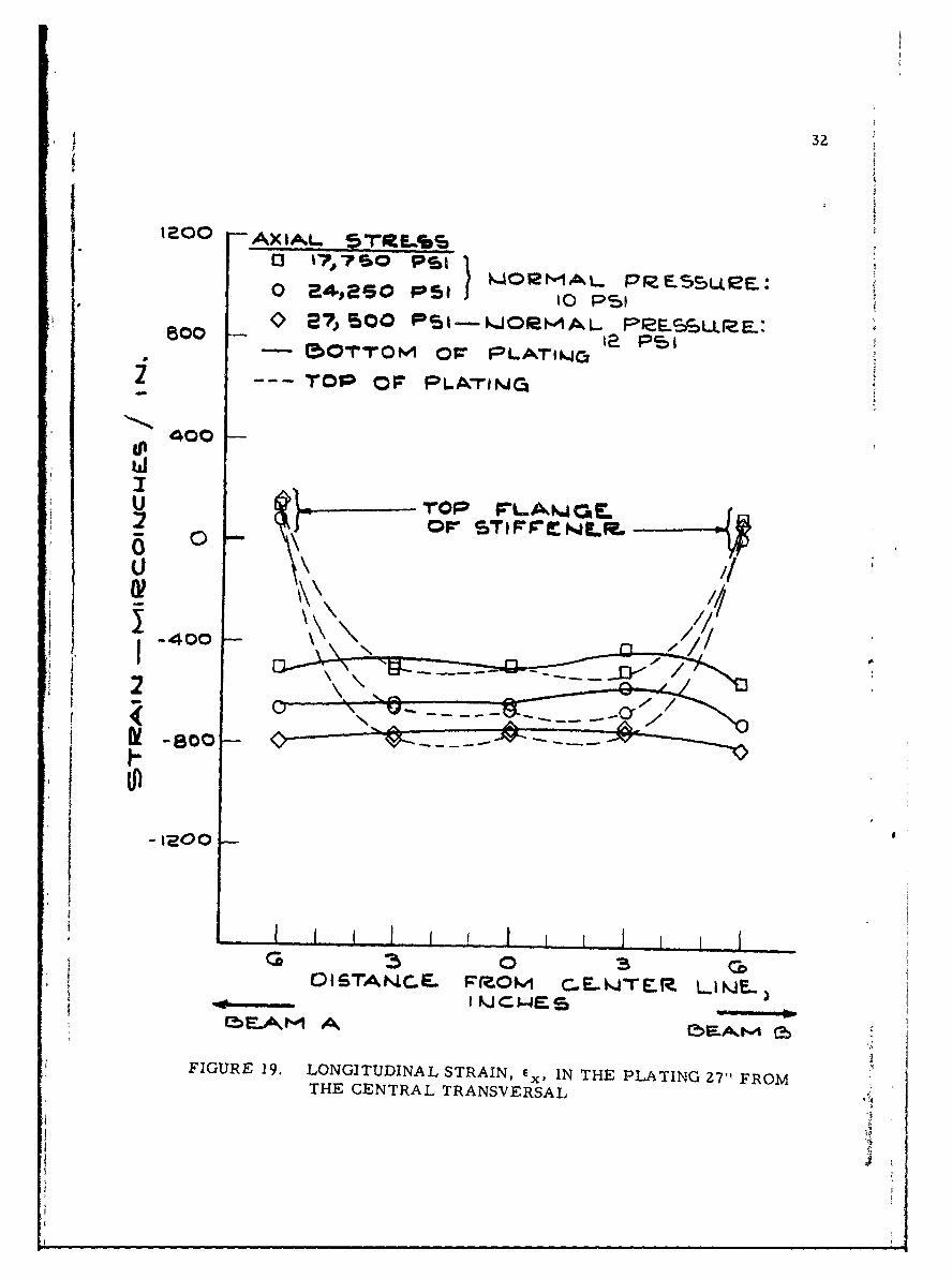
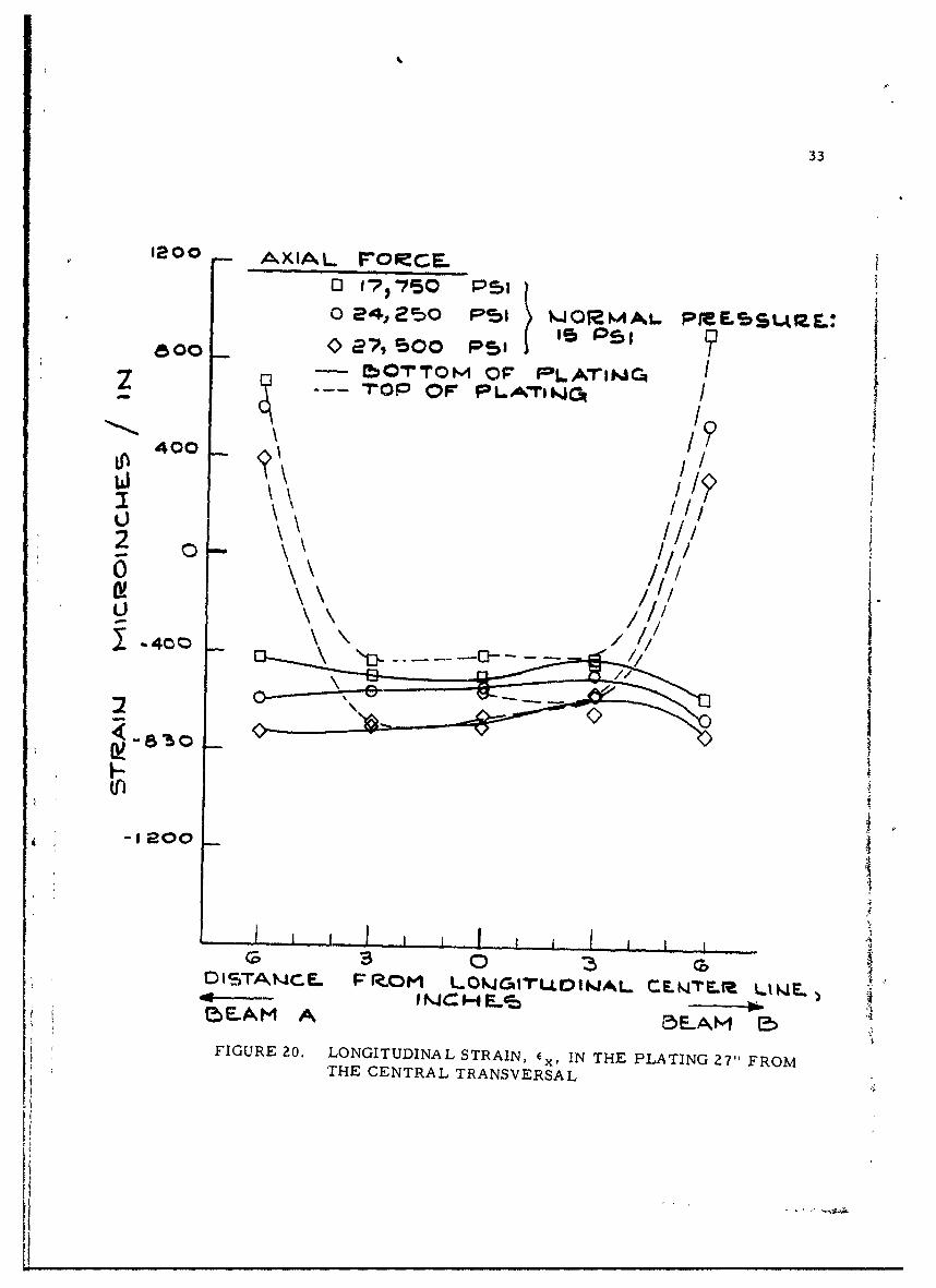
It will be seen from Figures 18, 19 and 20 that the longitudinal
strain in the plating, ex, is essentially uniformly distributed at all the
combinations of axial force and normal pressure. The greatest deviations
from uniformity are at the highest normal pressure of 15 psi. Further-
more, small and the magnitude does not change appreciably with normal
pressure. It does change, however, with a change in axial pressure. This
shows that: (a)the axial load is carried nearly uniformlyby the plating and (b)
the bending stresses in the longitudinal direction are small, These conclusions
28
2AXIAL 5T2FSLID 17, 750 P51 1
-'IO 0 a4*s ps), W0.4OA PreL55L.R
I-01O C5 s PSI
2 -BOTTrOM OF PL4~TINGTOP OF PLATIW4C.
ols~rA~JCE. rmom L.0NJGIToiNAL ""
lb LAM 5 .A M Eb
FIGURE 15. STRAIN, cIN THE PLATING 27"1 FROM THE CENTRALTRANSVEkAAL
29
1200
800&2 1
15OTTOM O F
Lf)
0 AXIALL P~fS5LSS
0 24,2so toI KlrM. F__SL0 P- 72 500 PSI - WJ0IMAL PP.LSLRE
2 ~ 150TTOW OF- PUAMtJC 12 PSITOP OP PLAMTNt(J
*-1200
I QIC H IB
FIGURE 16. STRAIN, c y,, IN THE PLATING 271" FROM THE CENTRALTRANSVERSAL
30
0200
800 e (oTTOM OF 4BrIF*FLIJLE A
400 c
002
U -400) AXAL SRLEPS0 g77Wo PSI
0 2412SO PSI k,-J0RMA.L P5eLSIZIE
-800- - 250T l0 1 PL lN
-- 0TOv OF L^TIN
DISTAN~CE. FZO L0QJqITLI?0IWAL.1%A"
FIGURE 17. STRAIN, C ,, IN THE PLATING 27" FROM THE CENTRALTRANSVERSAL
31
1200AXIAL STR~ESS
o 24250 PSI
800 ~ Soo PS-E50TTOM OFF PLATitJ
2 rQTP OF PLATIN4GI
ITOP F-LAW.ICFL or s-Tt4F-~f~u2
j-400
GAGS 5LO
LnIle00I.3
01IAf--R H LW iLIIA -NT.2LN -0 F i Ioo E
FIUR 18 OGTDNLSTAN ,I H PAIG2"FOTHE ENTRL TANSVRSA
3Z
I~0OAXIA.L. 5T~tEL%
o ~46O SI -WOR"WAL PieEsct~eE:_ --00- t pi
- 5OTYON1 O~r PLATiwo1 a ~
--- O oF- O LA-roeNLa
U4 0 0
:2 Ov STFrEL0
-400
A I i__ I I I
OlSTANCE. FROM C..WAJE.R LIKJE..)
EbLOh,1 A ~~~
FIGURE 19. LONGITUDINAL STRAIN, E x, IN THE PLATING 27" FROMTHE CENTRAL TRANSVERSAL
33
1200 AXIAL- PoMCE01 I7 750 PSI
80 e4, 250 P45 WOMAL PfMESSLAIL:
z - ~MO-T0M OF IPLAThJCq I- i~70P OF PLATIW4c3
400 A
2 Now
0
D I STA 114 c:L FIr.0M Lokj6iLtot.AL CLE r LU4L,l!)E.AM A 5r-AM~. 5
FIGURE 20. LONGITUDINAL STRAIN, c , IN THE PLATING 27" FROMTHE CENTRAL TRANSVERSAL
34
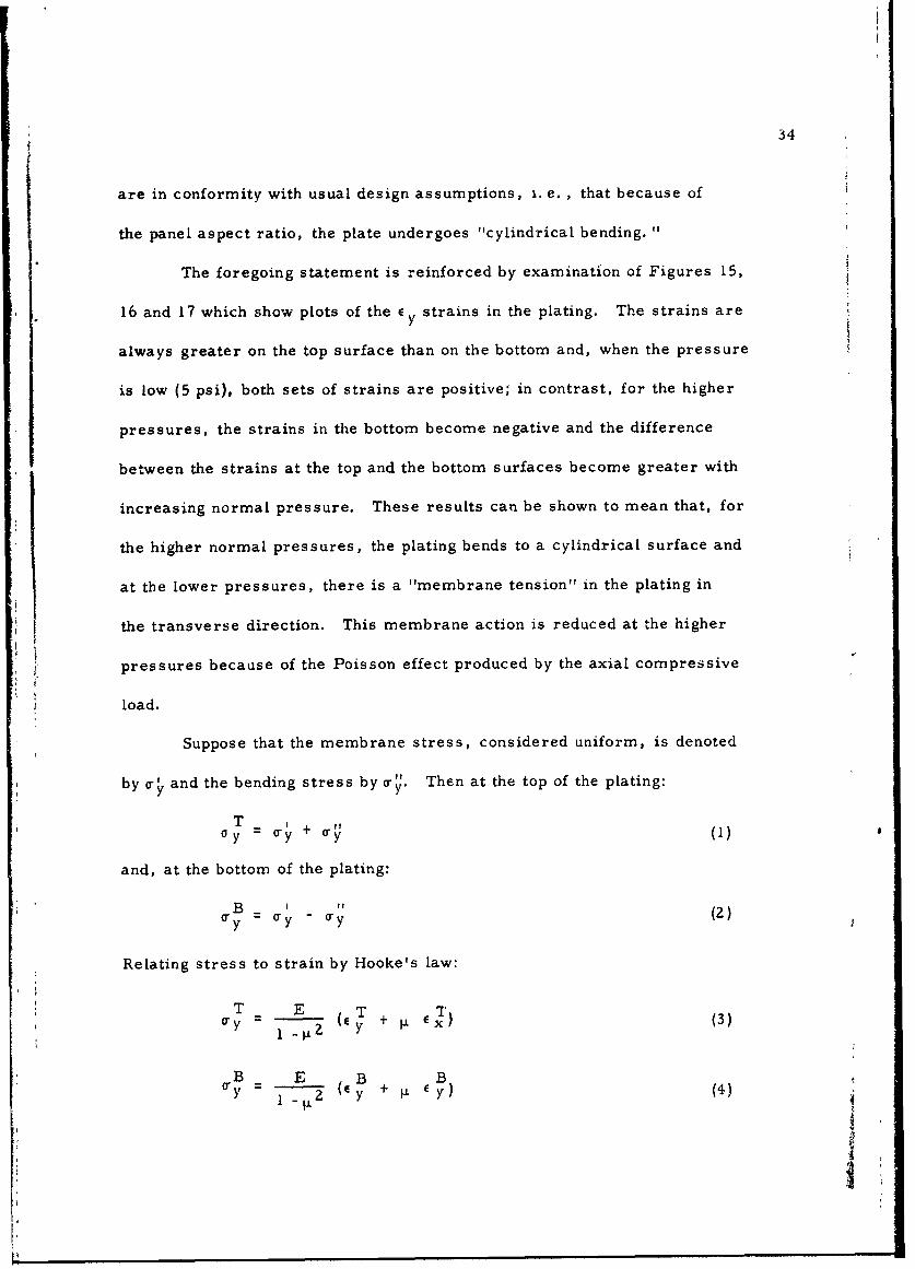
are in conformity with usual design assumptions, i. e., that because of
the panel aspect ratio, the plate undergoes "cylindrical bending.
The foregoing statement is reinforced by examination of Figures 15,
16 and 17 which show plots of the E y strains in the plating. The strains are
always greater on the top surface than on the bottom and, when the pressure
is low (5 psi), both sets of strains are positive; in contrast, for the higher
pressures, the strains in the bottom become negative and the difference
between the strains at the top and the bottom surfaces become greater with
increasing normal pressure. These results can be shown to mean that, for
the higher normal pressures, the plating bends to a cylindrical surface and
at the lower pressures, there is a "membrane tension" in the plating in
the transverse direction. This membrane action is reduced at the higher
pressures because of the Poisson effect produced by the axial compressive
load.
Suppose that the membrane stress, considered uniform, is denoted
by a- and the bending stress by a-y. Then at the top of the plating:
TO y Ty +y (1)
and, at the bottom of the plating:
B =' - "y (Z)ay y -
Relating stress to strain by Hooke's law:
T E T( + EX ) (3)
B E B By - 2 (Cy + 4 ) (4)
-Ii.
35
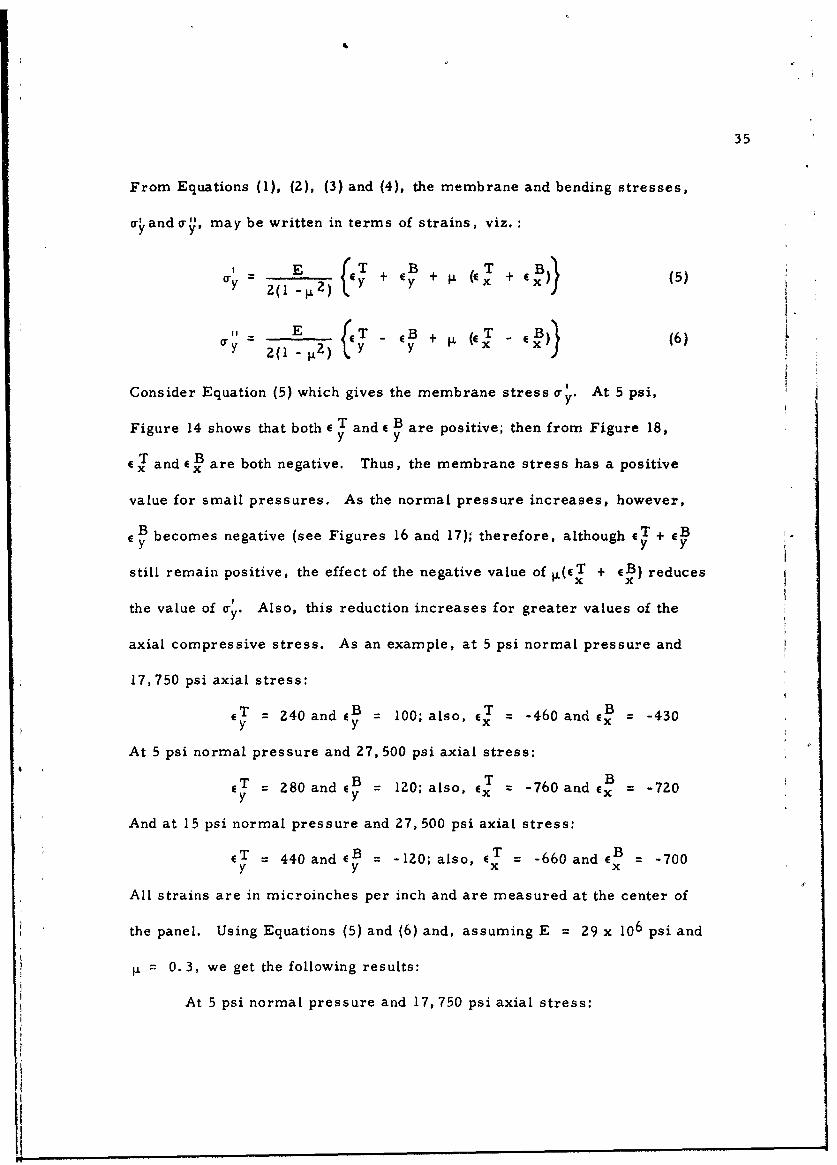
From Equations (1), (2), (3) and (4), the membrane and bending stresses,
a" and or, may be written in terms of strains, viz.:
. E + + (C. + f..' (5)
y 2(1 tz) Y y +j
Consider Equation (5) which gives the membrane stress a- At 5 psi,
Figure 14 shows that both e T and E B are positive; then from Figure 18,y y
and c B are both negative. Thus, the membrane stress has a positive
value for small pressures. As the normal pressure increases, however,
B becomes negative (see Figures 16 and 17); therefore, although ET + GBE y y
still remain positive, the effect of the negative value of (cT + GB) reduces!x
the value of a-. Also, this reduction increases for greater values of the
axial compressive stress. As an example, at 5 psi normal pressure and
17,750 psi axial stress:
CT = 240 and GB = 100; also, eT = -460 and eB = -430y y
At 5 psi normal pressure and 27, 500 psi axial stress:
CT = 280 and cB = 120; also, cT = -760 and B = -720
And at 15 psi normal pressure and 27, 500 psi axial stress:
(T = 440 and (B = -120; also, ET -660 and B -700y y x x
All strains are in microinches per inch and are measured at the center of
the panel. Using Equations (5) and (6) and, assuming E 29x 106 psi and
0.3, we get the following results:
At 5 psi normal pressure and 17, 750 psi axial stress:
I
36
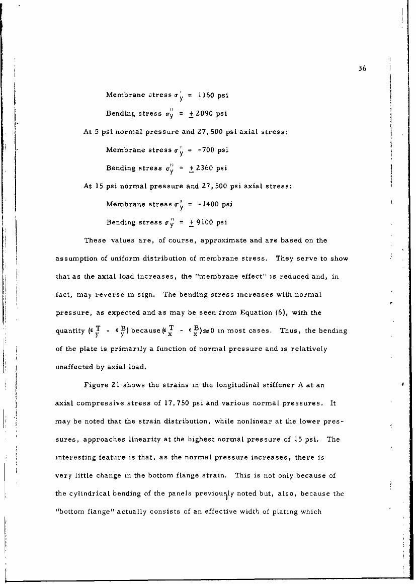
Membrane otress y 1160 psi
Bending stress -y = + 2090 psi
At 5 psi normal pressure and 27, 500 psi axial stress:
Membrane stress = -700 psi
Bending stress o-" = + 2360 psi
At 15 psi normal pressure and 27, 500 psi axial stress:
Membrane stress T y 1400 psi
Bending stress a-" = + 9100 psi
These values are, of course, approximate and are based on the
assumption of uniform distribution of membrane stress. They serve to show
that as the axial load increases, the "membrane effect" is reduced and, in
fact, may reverse in sign. The bending stress increases with normal
pressure, as expected and as may be seen from Equation (6), with the
quantity (e T -B) because(e T - EB) 0 in most cases. Thus, the bendingy y X
of the plate is primarily a function of normal pressure and is relatively
unaffected by axial load.
Figure 21 shows the strains in the longitudinal stiffener A at an
axial compressive stress of 17, 750 psi and various normal pressures., It
may be noted that the strain distribution, while nonlinear at the lower pres-
sures, approaches linearity at the highest normal pressure of 15 psi. The
interesting feature is that, as the normal pressure increases, there is
very little change in the bottom flange strain. This is not only because of
the cylindrical bending of the panels previously noted but, also, because the
"bottom flange" actually consists of an effective width of plating which
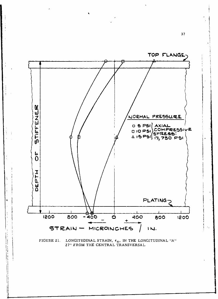
37
TOP rLAWGE-L
ui
L.L o 0 PS I(L 6.I.
ST" O T CENRALTSERAL INJ.
27 F
38
provides a measure of lateral restraint. In contrast, the top flange strains
change noticeably and the compressive strain in the web decreases rapidly
with the increase of pressure.
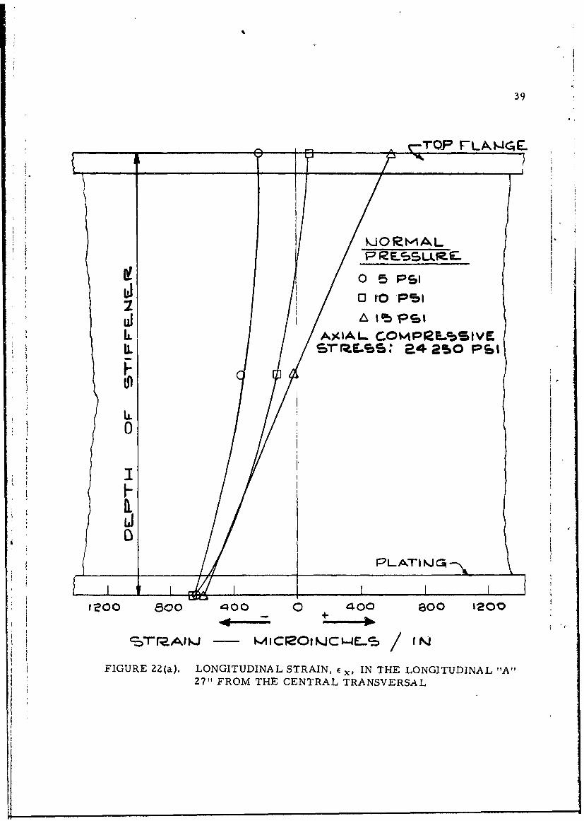
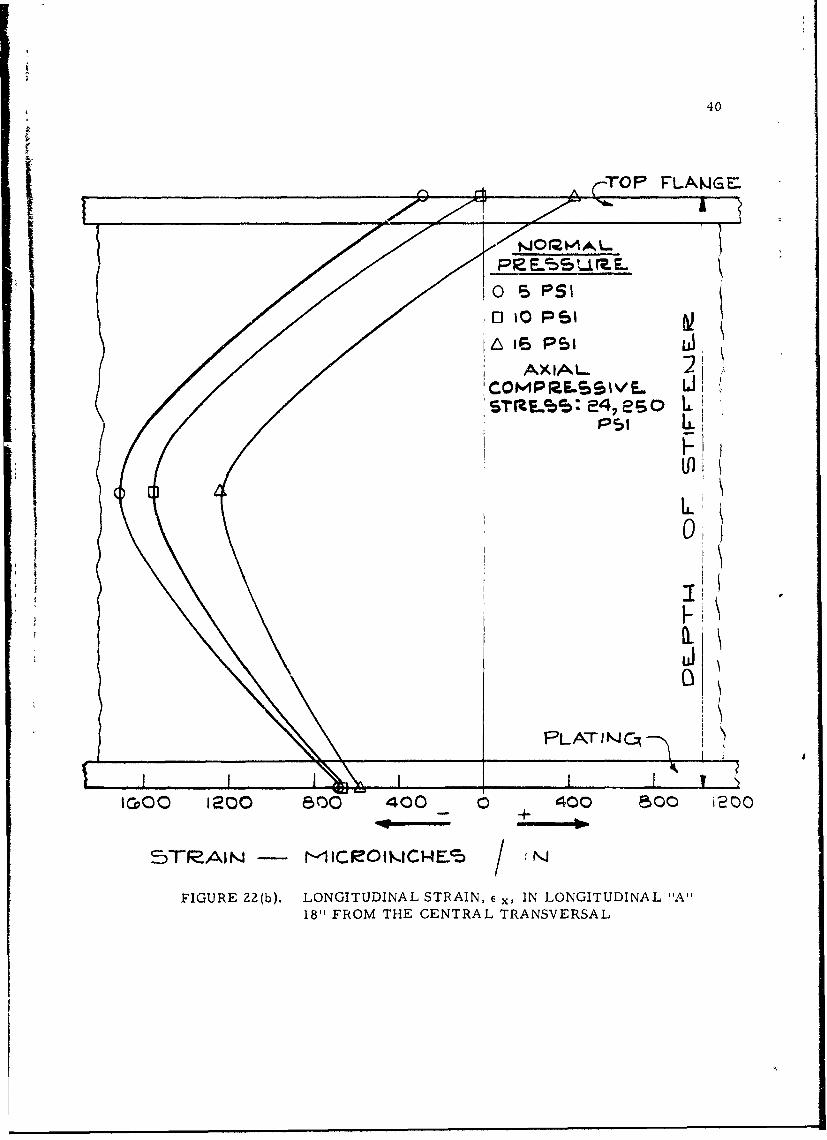
Figure 22(a) gives the strain distribution in the grillage longitudinals
at the axial stress of 24,250 psi. It will be noted that the strains in the top
flange of the longitudinal have changed little from their corresponding values
in Figure 21. The strains in the "bottom flange, " however, have increased
noticeably. Again, at the maximum pressure of 15 psi the strain distribution
is linear (almost perfectly linear in this case), with the geometric center of
the section experiencing zero strain.
These features lead to certain interesting conclusions. For instance,
since the top flange strains increase with normal pressure and have virtually
the same values at the axial stresses of 17,750 psi and 24,250 psi, we may
conclude that, as the axial load is increased, the axial compression is no
longer transferred to the top flange, and is therefore less uniformly dis-
tributed. Also, since the axial compressive strain in the bottom plating
increases with increase of axial load, we may conclude that a proportionately
greater part of the stress is transferred to the bottom plating.
However, as the normal pressure is increased, the strain distribu-
tion becomes nearly linear, approaching, approximately, the ideal case of
zero axial pressure. This phenomenon may be explained by the hypothesis
that with increase of normal pressure, the axial load tends to be taken by
the longitudinal boundaries of the grillage which are relatively rigid.
The stress in the bottom plating is given by:'
39
* IkIORNAL
' ' 1 o 5 psi
6 iL AXIAL C.OMP2E..SIlVF.
F I.
LI $
i
4. 0
PLATINJCq
0i,
IO0 800 400 400 800 1200
S -rrAIW. - MIC1OIC-S / IN
FIGURE 2Z(a). LONGITUDINAL STRAIN, x, IN THE LONGITUDINAL "A"27, FROM THE CENTRAL TRANSVERSAL
40
rop FLMJWGE:
0 PSI
fL 1O PSIu
AXIAL. 2
LJ\
PLATINJC itl
FLTI N ,.1
ICOC 1200 500 400 _0 400 500 i
5TIAI -~1I~O~i -E /+
FIGURE 22(b). LONGITUDINAL STRAIN, x, IN LONGITUDINAL "Al18" FROM THE CENTRAL TRANSVERSAL
41
ETx - (Cx + .L f Y)
Figures 15, 16 and 17 show that Ey increases with normal pressure. This
is to be expected because the plate has a strong curvature at the longitudinal
stiffeners and the symmetry of the structure prevents rotation of the longitudi-
nals; the panel, therefore, acts like a "fixed ended" plate. ex , on the other
hand, is practically unaffected by the normal pressure and as the preceding
equation shows, as normal pressure is increased, ox in the plating is reduced.
Since the total axial load does not change with increasing normal pressure,
this can only mean that part of the axial load is transferred to the boundaries.
This is very similar to the "effective width" phenomenon, long recognized
in the post buckling behavior of plating. Therein, it has been found that the
nature of the boundaries always plays an important part in the mechanisms
of failure and must, therefore, be taken into account in an ensuing analysis.
In summary, the conclusions are two-fold, viz. , (a) as the axial
load is increased, the bottom plating carries the bulk of the increase and
(b) as the normal pressure is increased, the axial load tends to be trans-
ferred to the boundaries of the griLlage.
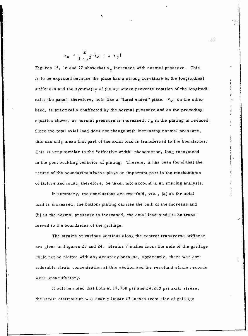
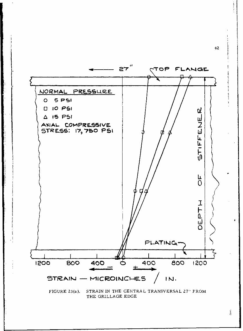
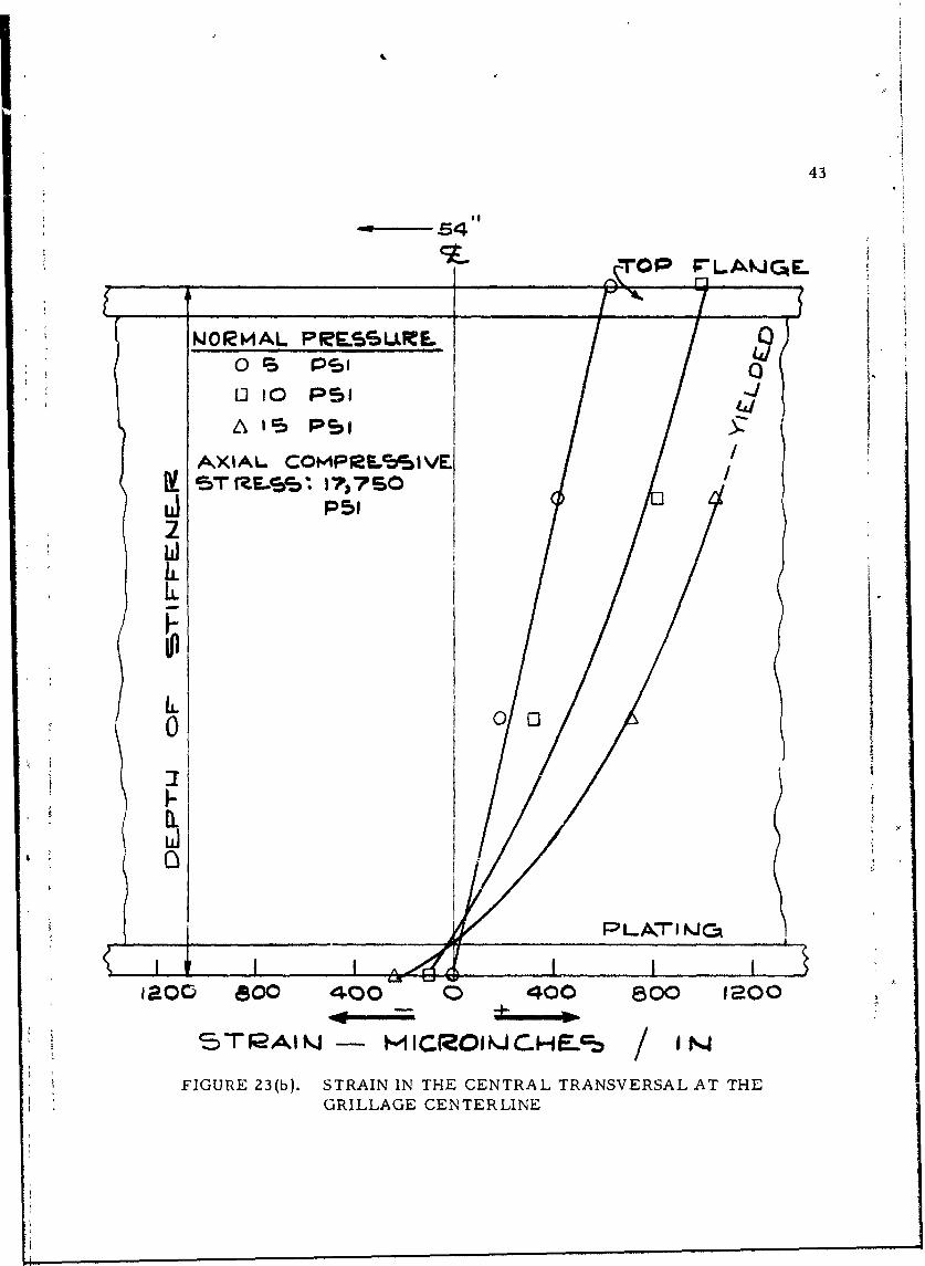
The strains at various sections along the central transverse stiffener
are given in Figures 23 and 24. Strains 7 inches from the side of the grillage
could not be plotted with any accuracy because, apparently, there was con-
siderable strain concentration at this section and the resultant strain records
were unsatisfactory.
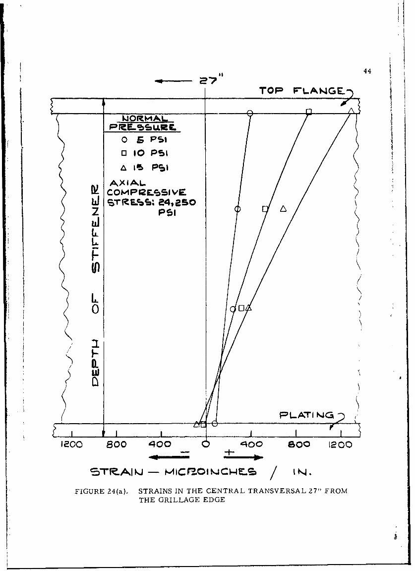
It will be noted that both at 17,750 psi and 24,250 psi axial stress,
the strain distribution was nearly linear 27 inches irom side of grillage
42
(JO1MAL P.LLP-E.
o 5P1
o 1o P s ia e 5PI uJ
A*'4AL. COtPRI-GSIVE 2SRI!ss: 7,7rO Po
U.uJL
1200 800 400 0 400 800 1200
5TeAl - kICROINCI-E5 / N.
FIGURE 23(a). STRAIN IN THE CENTRAL TRANSVERSAL 27" FROMTHE GRILLAGE EDGE
£4
43
54
W.OIRHAL PRE5SURF.0~ P151 10l10 Psi
A115 PSI
AXIAL C0tAP12L~cjIvE&5 5 VES 17,7 SO
2
00
P L-Al-FI ki CA
Iaoc 800 400 0 400 800 taoo
5TAIKJ - IC(ROIQCHE.%~
FIGURE 23(b). STRAIN IN THE CENTRAL TRANSVERSAL AT THEGRILLAGE CENTERLINE
44~27P
TOP FLANGE-)
W~ORV.1AL
o 6 PSI ,13 10 PSI
IS PSI
AXIALCOMP12ESSeVEST 1.L%: e4,e2So
Psi
IL
I(I
IL
( __ ____PLATI WGJ;
I /
--1o 00 0 400 So0 1200
I C: r20I JC 4F. 14
/
FIGURE 24(a), STRAINS IN THE CENTRAL, TRANSVERSAL 27" FROMI, THE GRILLAGE EDGE
[ /._L
45
o- - 1 i F-LANCF- L
P4reESJAAL0o %s, / TOP FLANGNE'
0 to I / /lLDE-0A 16 PSId
AXIAL /7 oC,COMPMF-ScaVE-STIMS1. 24,albo..[/
; //K 2i
/ Ii.
IL01
PI I NJ CA
oo 800 ,400 00 0 lcl
'II
FIGURE 24(b)., STRAINS IN THE CENTRAL TRANSVE,.2 ,AL AT THEGRILLAGE CENTERLINE
2 O
46
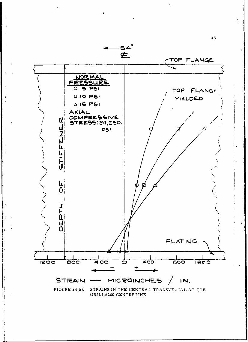
and, at low pressures, this linearily was maintained to the longitudinal
centerline of the grillage. Moreover, at all pressures, the zero strain
axis is close to the bottom plating. This shows that the effective width of
plating is virtually unaffected by either the axial load or the normal
pressure. Thus, the behavior of transversals, because of the absence of
axial loads, is quite different from that of the longitudinals.
!I
47
IV. CONCLUSIONS
In summary, analysis of the data leads to the following general
interrelated conclusions, most of which tend to confirm the assumptions
usually made for grillage design. These are:
1) The axial load is carried principally by the grillage
plating. The resultant compressive stress is fairly
uniform, particularly at low axial loads, and longitudinal
bending induced by axial load is small.
2) Bending stress in the grillage is primarily a function of
normal pressure. At low normal pressures, i.e. , 5- 10
psi in the case of the grillage tested, a transverse mem-
brane tension resulting from edge clamping restraint is
evident. This effect does not increase in direct proportion
as normal pressure is increased because of the Poisson
effect induced by the axial compression.
3) As the normal pressure is increased from, say 10 psi in
the case of the grillage tested, a greater portion of the
axial load is transferred to the relatively rigid side
boundaries.
4) For the transverse beams the effective width of plating is
virtually unaffected by either axial load or normal pressure.
In addition to the above conclusions which concern the actual
behavior of the tested grillage, it is also to be mentioned that - in retro-
tI
48
spect - certain changes in specimen geometry, in test instrumentation
and test procedure and in design of the test hardware would yield other
information of considerable value in grillage design methods. In
particular, it must be noted that the manner in which the axial load is
introduced into the grillage is of paramount importance to the specimen
failure mode. As previously mentioned, failure in the grillage tested
was via local crippling at the load end; therefore, the true ultimate
strength of the grillage was not determined.
A discussion regarding desireable modifications which should be
made in the event of future tests follows in Appendix A of this report.
A-2
APPENDIX A
OUTLINE OF A RECOMMENDED PROGRAM
Outlined in the pages following is a program designed to comple-
ment the effort described in the preceding sections by means of further
tests performed on grillages slowly loaded from initial elastic conditions
until final plastic collapse. The program objective is not merely to
ascertain collapse conditions, but, also, to learn enough about the struc-
tural response so that analytical predictions for other grillages operating
under similar conditions will be possible. It is necessary, therefore, to
devote considerable attention to the analysis of test results at every stage,
starting first with strain data from the better-understood elastic range,
then continuing on into the elasto-plastic zange. By so doing, it will be
possible to convert strains in the elastic range to stresses and thereby
calculate resisting moment, effective width, etc. , in order to form a
conceptual understanding of the grillage behavior. Once plastic behavior
is initiated (and, in the grillage this will no doubt occur simultaneously
at several sections), strains cannot easily be converted to stresses and
it will then be necessary to develop a reasonable hypothesis regarding the
grillage behavior. Such a hypothesis will not be precise in all details but
will, nevertheless, allow prediction of the grillage response close to its
final collapse load. The elastic stage information will be useful, apart
from its own intrinsic value, mainly in serving as a guide to the likely
behavior in the later elasto-plastic stage.. In this regard, it should be
PRECEDING PAGE BLANK
A-3
remembered that the grillage will never oecome completely plastic
throughout the conditions of the test. Much of the plating will remain
elastic and, quite probably, large portions of the stiffening beams also.
However, the grillage will become plastic at several critical points and
its remaining capacity for taking additional load will drop in dramatic
fashion.
Thus, it would seem necessary to concentrate attention at those
sections of the grillage which are likely to be critical in determining
"collapse. " In the case of purely lateral Loads, the critical sections are
at the intersections cf the stiffeners which, theoretically, form "plastic
hinges. " Although the behavior may be different in the case of both axial
and lateral load, it is believed that behavior at the intersection points or
"nodes" will still be of importance in determining collapse. Nevertheless,
since the grillage has plating, the behavior of the beams between nodes
cannot be wholly disregarded, especially when the geometric center of
the grillage is not also a node.
The foregoing discussion is intended to show, first, that by choice
of critical locations, it is possible to reduce the number of strain gages
from that employed in the test reported in this document and, secondly,
that the study of the elastic stage must precede loading of the grillage
into the plastic range. It is to be recalled that, in the tests discussed
herein, that certain combinations (Data Points) of axial and lateral loads
were used; therefore, there was no guarantee that certain sections of the
A-4
grillage had not already yielded during test at a prior Data Point. Also,
when both axial and lateral loads were varied, the analysis of strain data
became quite difficult.
For these reasons, then, a program as outlined below appears
to have merit:
(a) A modification of the test facility - This modification .s of
a minor nature, involving only additional torsional stiffness
and bending strength for the transverse I-beam at the load-
ing end of the loading frame. Previous tests showed that,
at large axial loads and normal pressures, the beam was
bent out of plane and, also, twisted; this resulted in an
eccentricity of the applied load.
(b) Test three new grillages of different proportions - One of
the major difficulties in the previous tests was associated
with local crippling of the grillage specimen, particularly
at the loading end. This feature of the behavior of the
grillage is now well understood and the manner in which
the load should be transferred into the grillage is apparent.
As has already been mentioned, it is desireable to obtain strain
data in the purely elastic stage of the grillage before loading into the
plastic state. For this purpose, a combination of small axial loads and
normal pressures are necessary. The procedure, therefore, should be
to maintain the axial load constant and increase the normal pressure in
steps of, say, two psi up to about ten psi. then unload the grillage com-
A-5
pletely. The derived data should then be analyzed t3 determine bending
moments, and effective width of plating in each direction. Next, a
lateral load of about ten or fifteen psi should be applied and the axial load
increased in steps until collapse occurs.
From the strain data in the elastic stage and, also, from this
information gained in the subsequent loading into the plastic range, an
analytical procedure should be developed for predicting the deflections of
the elastic-plastic grillage as well as its final collapse load.
Of the three tests proposed, the first two should carry a fairly
large number of strain gages and tested similarly.: In addition, the third
and last test should carry a minimum of instrumentation at locations
dependent upon the results of the first two. The main purpose of this test
would be to verify the analysis methods, particularly as regards to predic-
tion of the grillage behavior in the plastic range.
As to specific configuration and instrumentation for the proposed
tests, it is to be kept in mind that, in the first two tests, the major
emphasis would be on data acquisition and theoretical analysis while in
the last test, the emphasis should shift to verification and confirmation.
The first two specimens, therefore, would not be radically different from
that previously tested; the third, however, would be decidedly heavier and,
thus, becomes the medium for checking analytical procedures developed
on the basis of Specimens 2 and 3 test results. Suggested sections are
as given below, starting with the designation 'Specimen 2 to differentiate
from the previous tests which may be called ''Specimen 1.
.A-6
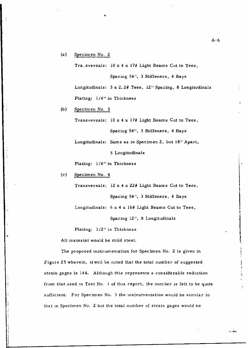
(a) Specimen No. 2
Tra.sversals: 10 x 4 x 17# Light Beams Cut to Tees,
Spacing 54", 3 Stiffeners, 4 Bays
Longitudinals: 3 x 2.2# Tees, 12"1 Spacing, 8 Longitudinals
Plating: 1/4"1 in Thickness
(b) Specimen No. 3
Transversals, 10 x 4 x 17# Light Beams Cut to Tees,
Spacing 54", 3 Stiffeners, 4 Bays
Longitudinals: Same as in Specimen 2, but 18" Apart,
5 Longitudinals
Plating: 1/4" in Thickness
(c) Specimen No. 4
Transversals, 12 x 4 x 22# Light Beams Cut to Tees,
Spacing 54", 3 Stiffeners, 4 Bays
Longitudinals: 6 x 4 x 16# Light Beams Cut to Tees,
Spacing 12", 8 Longitudinals
Plating: 1/2" in Thickness
All material would be mild steel.
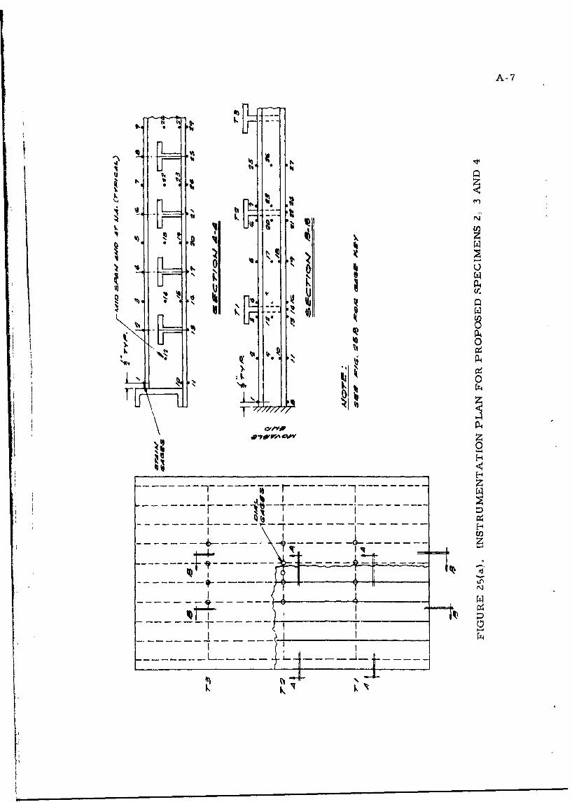
The proposed instrumentation for Specimen No. 2 is given in
Figure 25 wherein, itwill be noted that the total number of suggested
strain gages is 144. Although this represents a considerable reduction
from that used in Test No. I of this report, the number is felt to be quite
sufficient. For Specimen No. 3 the instrumentation would be similar to
that in Specimen No. 2 but the total number of strain gages would be
A-7
* P4
I. N
* 44
A-8
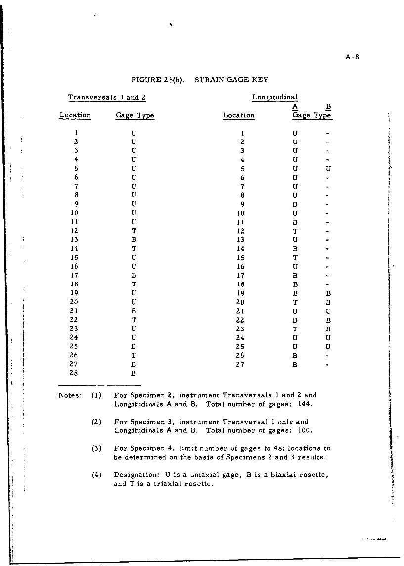
FIGURE 25(b). STRAIN GAGE KEY
Transversals I and 2 LongitudinalA B
Location Gage Type Location Gage Type
1 U I U -
2 U 2 U -
3 U 3 U -
4 U 4 U -
5 U 5 U U6 U 6 U -
7 U 7 U -
8 U 8 U -
9 U 9 B -
10 U 10 U -
11 U 11 B12 T 12 T -
13 B 13 U -14 T 14 B -15 U 15 T -16 U 16 U -17 B 17 B -18 T 18 B -19 U 19 B B20 U 20 T B21 B 21 U U22 T 22 B B23 U 23 T B24 U 24 U U
25 B 25 U U26 T 26 B -
27 B 27 B28 B
Notes: (1) For Specimen 2, instrument Transversals I and 2 andLongitudinals A and B. Total number of gages: 144.,
(2) For Specimen 3, instrument Transversal I only andLongitudinals A and B. Total number of gages: 100.
(3) For Specimen 4, limit number of gages to 48; locations tobe determined on the basis of Specimens 2 and 3 results.
(4) Designation: U is a uniaxial gage, B is a biaxial rosette,and T is a triaxial rosette.
A-9
reduced to 100. This would be accomplished by dropping out the gages
on the Transversal No. 1, see Figure 25, Specimen No. 4 would be
instrumented with a maximum of 48 strain gages at, as previously men-
tioned, locations dependent upon the results of Specimens 2 and 3.
It is felt that the above program would materially add to the tests
described in this report and, in addition, lead to a more thorough under-
standing of the grillage problem as a whole.
I
4
.4
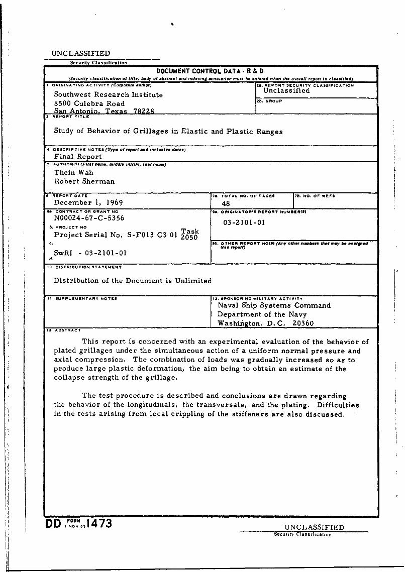
UNCLASSIFIEDSecurity Classification
DOCUMENT CONTROL DATA. R & D(Security classification of title, body of abstract and ,ndexing annotation must be entered when the overall report is clasilfied)
I ORIGINATING ACTIVITY (Corporate author) |2a. REPORT SECURITY CLASSIFICATION
Southwest Research Institute Unclassified
8500 Culebra Road 2b. GROUPSan Antonio. Texas 7229
3REPORT TITLE
Study of Behavior of Grillages in Elastic and Plastic Ranges
4 DESCRIPTIVE NOTES (7*ypo of roport and inclusive delta)
Final ReportS AU THORISI (Firet name, middle Initial, last name)
Thein Wah
Robert Sherman
6 REPORT DATE ?a. TOTAL NO. OF PAGES 7b. NO. OF REFSDecember 1, 1969 48
sa CONTRACT OR GRANT NO ga. ORIGINATORIS REPORT NUMBER(S)
N00024-67-C-5356 03-2101-01b. PROJECT NO T askProject Serial No. S-F013 C3 01 2050
c. b. OTHER REPORT NOIS) (Any other numbeff that my be asalgnedthis report)
d.SwRI - 03-2101-01d.
10 DISTRIBUTION STATEMENT
Distribution of the Document is Unlimited
I SUPPLEMENTARY NOTES 12. SPONSORING MILITARY ACTIVITY
Naval Ship Systems CommandDepartment of the NavyWashirigton, D.C. 20360
13 ABSTRACT
This report is concerned with an experimental evaluation of the behavior ofplated grillages under the simultaneous action of a uniform normal pressure andaxial compression. The combination of loads was gradually increased so as toproduce large plastic deformation, the aim being to obtain an estimate of thecollapse strength of the grillage.
The test procedure is described and conclusions are drawn regardingthe behavior of the longitudinals, the transversals, and the plating. Difficultiesin the tests arising from local crippling of the stiffeners are also discussed.
DD ,NOV 1473 UNCLASSIFIEDSecuritv ClasstfIcatIon