Embed Size (px)
Citation preview

Page 144 www.ijiras.com | Email: [email protected]
International Journal of Innovative Research and Advanced Studies (IJIRAS)
Volume 3 Issue 5, May 2016
ISSN: 2394-4404
Study Of Bladeless Fan
A. Swamynathan
Master Of Engineering In Manufacturing Engineering,
Department Of Mechanical Engineering,
Kathir College Of Engineering, Coimbatore,
Anna University, Chennai
Dr. J. Amos Robert Jayachandran
Project Supervisor,
Head of the Department, Dept. of Mechanical Engineering,
Kathir College of Engineering,
Coimbatore
I. INTRODUCTION
The fan structure and meshing and analysis made to
compare to get better fan. The Computational fluid analysis
made to get the velocity and flow. The optimum performance
achieved in impeller and the bladeless fan also proved by this
study.
II. BLADELESS FAN STRUCTURE
A. STRUCTURE DESIGN
Figure 1
The structure of bladeless fan consists one base and ring
unit.
The base inside the motor-impeller unit mounted. Bottom
of base have a flat surface to seat on surfaces. Base also has
two potions. One is seating on flat face and another potion has
spherical joint type with bottom. This joint used to tilt the fan
required angle.
Also base have flat slots to air inlet .Above the slots have
a conical potion towards impeller. The impeller connected
with motor.
The ring units have passage to air in various shapes. Then
the ring end formed as airfoil shape.
The motor 60 to 100 watt electrical motor.an impeller
connected with motor shaft. The impellers are various designs
available. The
B. IMPELLER
Figure 2
Abstract: The performance comparison between ordinary fan and bladeless fan. Analysis with Computational fluid
dynamics with software. The impeller shapes and performances comparison also made to choose better impeller.

Page 145 www.ijiras.com | Email: [email protected]
International Journal of Innovative Research and Advanced Studies (IJIRAS)
Volume 3 Issue 5, May 2016
ISSN: 2394-4404
Impeller manufactured by fiber or pvc material. This is
the most important product as heart fan and blowers. Let inlet
duct size be 10% higher than impeller eye size or impeller
inlet Diameter. This will make conical insertion of inlet duct
and flow acceleration at impeller eye or inlet.
Assuming no loss during 90º turning from eye inlet to
impeller inlet, the eye inlet velocity vector will remain same as
absolute velocity vector at the entry of impeller.
Blade Profile is made by tangent arc method [26]. When
this method is used, the impeller is divided into a number of
assumed concentric rings, not necessarily equally spaced
between inner and outer radii. The radius Rb of the arc is
defining the blade shape between inner and outer radii.
C. AIR MULTIPLIER
Figure 3
The air multiplier (Figure 1), efficiently creates laminar
airflow with no buffering or uneven airflow, a characteristic
that a wind tunnels settling chamber seeks to reduce. This
elimination of buffering and the creation of steady laminar
flow is of great interest to designers of the wind tunnel,
particularly, the possibility of placing the test target closer to
the source of flow (Figure 2). Our results from laser Doppler
anemometry show that there are two regions close to the
source of flow that over steady laminar flow.
D. AIRFOIL SHAPE
Figure 4
The direction of air flow is controlled by the shape of fan
output ring. By this shape the air flow is increased. The shapes
have output side is taper and curved bend towards outside. The
profile consists a tiny slot to air flow for the propelled air.
E. MOUNTING SHAFT
Figure 5
A shaft connected to the impeller and motor also mounted
to base. A stainless shaft has both ends bearing support. Shaft
rotated by motor.
F. MAIN BODY
Figure 6
A shaft connected to the impeller and motor also mounted
to base. A stainless shaft.
III. CFD MESHING
A. ORDINARY FAN MESH DETAILS

Page 146 www.ijiras.com | Email: [email protected]
International Journal of Innovative Research and Advanced Studies (IJIRAS)
Volume 3 Issue 5, May 2016
ISSN: 2394-4404
Calculation Mesh
Number of cells in X 30
Number of cells in Y 30
Number of cells in Z 32
Table 1: Basic Mesh Dimensions
Total cells 32755
Fluid cells 31175
Solid cells 22
Partial cells 1558
Irregular cells 0
Trimmed cells 0
Table 2: Number Of Cells
B. ORDINARY FAN MESH DETAILS
Calculation Mesh
Number of cells in X 52
Number of cells in Y 6
Number of cells in Z 6
Table 3: Basic Mesh Dimensions
Total cells 8312
Fluid cells 3535
Solid cells 566
Partial cells 4211
Irregular cells 0
Trimmed cells 0
Table 4: Number Of Cells
IV. CFD ANALYSIS
A. ORDINARY FAN FLOW REPORT
Figure 7
Figure 8
Figure 9
B. STAGES OF AIRMULTIPLIER
The impeller sucks the air through bottom holes in the
housing.
Figure 10
The air moved through the port towards up to the output
profile.
Figure 11

Page 147 www.ijiras.com | Email: [email protected]
International Journal of Innovative Research and Advanced Studies (IJIRAS)
Volume 3 Issue 5, May 2016
ISSN: 2394-4404
The air flows towards front through the slit.
Figure 12
The flow of air by the profile of airfoil shape.
Figure 13
Because of the space in center of profile is also pull
toward front due to induction of air.
SC
HE
MA
TIC
D
IAG
RA
M
OF
A
IRF
LO
W
TH
RO
UG
H
BL
AD
EL
ES
S F
AN
Figure 14
C. IMPELLERS COMPARISION:
We are going to compare three different shape impellers.
Those structure differences as follows:
Generally all impeller diameter 190mm and 60mm height.
Impeller 1
Tilted blade
Straight leafs
Outer diameter ring taper shaped
Impeller 2
Plain spiral blade
Tip of blade taper as spiral
Without outer ring
Impeller 3
Spiral blade
Tip of spiral blade have straight edge
Without outer ring
D. IMPELLER COMPARATIVE RESULTS
Impeller Velocity (m/s) Pressure(Pa) Flow(m3/min)
Imp 1 1.016 101325.3 1.72
Imp 2 49.248 114130.87 83.4
Imp 3 0.983 101325.1 1.67
Table 4
We going to fit the impeller No.2 to blade less fan(air
multiplier)
E. IMPELLER CFD ANALYSIS RESULT
Figure 15
Figure 16
Page 148 www.ijiras.com | Email: [email protected]
International Journal of Innovative Research and Advanced Studies (IJIRAS)
Volume 3 Issue 5, May 2016
ISSN: 2394-4404
Figure 17
F. IMPELLER 2
Figure 18
Figure 19
Figure 20
G. IMPELLER 3
Figure 21
Figure 22
Figure 23
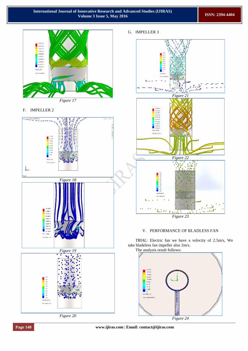
V. PERFORMANCE OF BLADLESS FAN
TRIAL: Electric fan we have a velocity of 2.5m/s, We
take bladeless fan impeller also 2m/s.
The analysis result follows:
Figure 24

Page 149 www.ijiras.com | Email: [email protected]
International Journal of Innovative Research and Advanced Studies (IJIRAS)
Volume 3 Issue 5, May 2016
ISSN: 2394-4404
Figure 25
Figure 26
Figure 27
COMPARISION WITH ORDINARY FAN
Fan Ordinary
(electrical)
Air
multiplier
Differe
nce
percen
tage
Velocity
(m/s)
2.534 18.82 16.286 640%
Pressure 101332.59 114575.2 13242. 13%
(Pa) 6 67
Flow
(m3/s)
0.351 2.364 2.013 600%
Table 5
VI. CONCLUSION
Hence I proved the result of bladeless fan 6 times better
than ordinary fan which also maximized performance also
optimized size.
ACKNOWLEDGEMENT
Words are often less to revels one’s deep regards. With an
understanding that works like this can never be the outcome of
a single person, I take this opportunity to express my profound
sense of gratitude and respect to all those who helped me
though the duration of this work.
I heartily express my profound gratitude to our respected
Chairman Thiru. E. S. Kathir for his constant support. I wish
to express my deep gratitude to our beloved Principal Mr. P.
Murthi for all the motivation and moral support rendered by
him.
My sincere thanks to our Head of the Department Dr. J.
AMOS ROBERT JAYACHANDRAN for providing me all
the necessary facilities to complete my project phase I
successful. His cooperation, experience and deep insight into
the subject has not only improved my vision in this field but
quality of this work also. I acknowledge with gratitude and
humility to my faculty guide Dr. J. AMOS ROBERT
JAYACHANDRAN Assistant Professor, Department of
Mechanical Engineering, Kathir college of engineering for his
valuable guidance, proper advice, which helped me to bring
this present work upto this level. I also take pride of myself
being son of ideal parents for their everlasting desire, sacrifice,
affectionate blessings, care and support nothing would have
been possible.
REFERENCES
[1] Air multipliers Wikipedia
[2] Blade less fan broachers
[3] Pneumatics kit
[4] Fluid dynamics